Hv 2514131415
3
Gulnar Perveen / International Journal of Engineering Research and Applications (IJERA) ISSN: 2248-9622 www.ij era.com Vol. 2, Issu e5, September- October 2012, pp.1413-1415 1413 | P a g e Low Power DCT Implementation In An Image Compression System Gulnar Perveen Solar Energy Centre, Ministry of New & Renewable Energy, CGO Complex, New Delhi, India Abstract Low power serves as the most important challenges to maximize battery life & to save the energy for many signal-processing system designs, particularly in multimedia cellular applications and multimedia system on chip design. The 2-D DCT is a commonly used frequency transformation in compression algorithms. In this paper, an Efficient Baseline 2- D DCT Architecture is compared with the Row/Column Approach, a Distributed Arithmetic Architecture & Fully Pipelined DCT Architecture for wireless Image Compression Systems. It is observed that the Row/Column DA DCT Architecture provides power saving of 24.4% and the Fully Pipelined Architecture provides power saving of 16.4% as compared to 2-D DCT Baseline Architecture. The speed is also measured & observed that Fully Pipelined Architecture exploits the principle of pipelining & parallelism to obtain throughput of 4.703 GHz. Keywords-DCT (Discrete Cosine Transform), 2- D(Two-Di mensiona l), DA(Distributed Ar ithmetic). I. ROW /COLUMN ARCHITECTURE In this an 8-point 1-D DCT is applied to 8 rows, and then again to each of the 8 columns. The 1-D algorithm that is applied to both the rows and columns are the same. Therefore, it could be possib le to use the identical pieces of hardware to do the row computation as well as the column computation. The bulk of the design and computation is in the 8-point 1-D DCT block, which can potentially be reduced 16 - 8 times for each row and 8 times for each column. Therefore, the fast algorithm for computing 1-D DCT is usually selected. The DCT core processor implements a Row-Column Distributed Arithmetic fast DCT algorithm enhanced with the activity reduction methods coefficients. The Row/Column Architecture has two 1-D DCT units connected through transposition matrix memory. Design is synchronous, with single positive clock edge and no internal tri-state buffers. This has RAM for storing product results after first DCT stage for maximized performance. This way both 1- D DCT units can work in parallel. This architecture takes 8 bit input data and produces 12 bit output using 12 bit DCT matrix coefficients [4]. Figure 1. Row/Column Approach Distributed arithmetic DCT Architecture, D0-D7: Registers. In the above architecture, when second stage of DCT reads out data from transposition memory 1, first DCT stage can populate second transposition memory with new data. 1-D DCT use Distributed Arithmetic with butterfly computation to compute DCT values. Because of parallel DA they need considerable amount of ROM memories to compute one DCT value.
-
Upload
anonymous-7vppkws8o -
Category
Documents
-
view
219 -
download
0
Transcript of Hv 2514131415
7/31/2019 Hv 2514131415
http://slidepdf.com/reader/full/hv-2514131415 1/3
Gulnar Perveen / International Journal of Engineering Research and Applications (IJERA)
ISSN: 2248-9622 www.ijera.com Vol. 2, Issue5, September- October 2012, pp.1413-1415
1413 | P a g e
Low Power DCT Implementation In An Image Compression
System
Gulnar PerveenSolar Energy Centre, Ministry of New & Renewable Energy, CGO Complex, New Delhi, India
AbstractLow power serves as the most important
challenges to maximize battery life & to save the
energy for many signal-processing systemdesigns, particularly in multimedia cellular
applications and multimedia system on chip
design. The 2-D DCT is a commonly used
frequency transformation in compression
algorithms. In this paper, an Efficient Baseline 2-
D DCT Architecture is compared with the
Row/Column Approach, a DistributedArithmetic Architecture & Fully Pipelined DCT
Architecture for wireless Image Compression
Systems. It is observed that the Row/Column DA
DCT Architecture provides power saving of
24.4% and the Fully Pipelined Architectureprovides power saving of 16.4% as compared to
2-D DCT Baseline Architecture. The speed is also
measured & observed that Fully Pipelined
Architecture exploits the principle of pipelining
& parallelism to obtain throughput of 4.703 GHz.
Keywords-DCT (Discrete Cosine Transform), 2-
D(Two-Dimensional), DA(Distributed Arithmetic).
I. ROW /COLUMN ARCHITECTURE
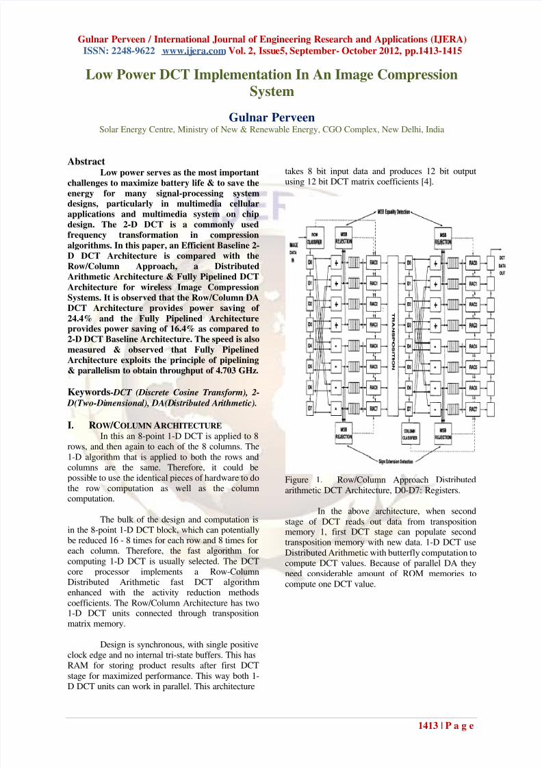
In this an 8-point 1-D DCT is applied to 8rows, and then again to each of the 8 columns. The
1-D algorithm that is applied to both the rows andcolumns are the same. Therefore, it could bepossible to use the identical pieces of hardware to dothe row computation as well as the columncomputation.
The bulk of the design and computation isin the 8-point 1-D DCT block, which can potentially
be reduced 16 - 8 times for each row and 8 times foreach column. Therefore, the fast algorithm for
computing 1-D DCT is usually selected. The DCTcore processor implements a Row-ColumnDistributed Arithmetic fast DCT algorithmenhanced with the activity reduction methods
coefficients. The Row/Column Architecture has two1-D DCT units connected through transpositionmatrix memory.
Design is synchronous, with single positiveclock edge and no internal tri-state buffers. This hasRAM for storing product results after first DCT
stage for maximized performance. This way both 1-D DCT units can work in parallel. This architecture
takes 8 bit input data and produces 12 bit outputusing 12 bit DCT matrix coefficients [4].
Figure 1. Row/Column Approach Distributed
arithmetic DCT Architecture, D0-D7: Registers.
In the above architecture, when second
stage of DCT reads out data from transpositionmemory 1, first DCT stage can populate second
transposition memory with new data. 1-D DCT useDistributed Arithmetic with butterfly computation tocompute DCT values. Because of parallel DA theyneed considerable amount of ROM memories tocompute one DCT value.
7/31/2019 Hv 2514131415
http://slidepdf.com/reader/full/hv-2514131415 2/3
Gulnar Perveen / International Journal of Engineering Research and Applications (IJERA)
ISSN: 2248-9622 www.ijera.com Vol. 2, Issue5, September- October 2012, pp.1413-1415
1414 | P a g e
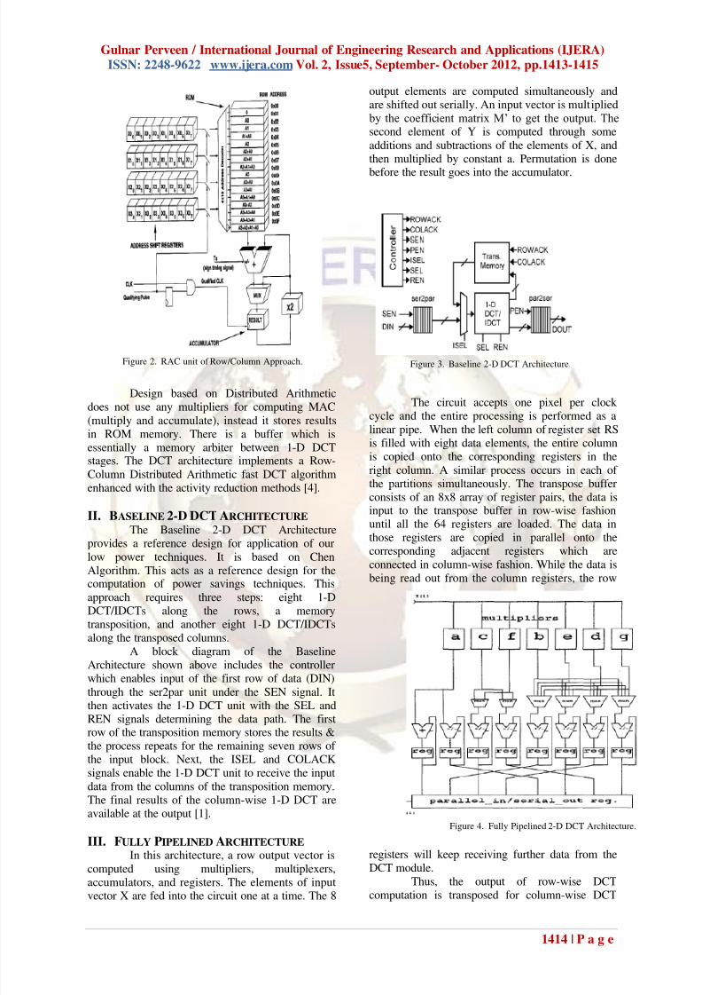
Design based on Distributed Arithmeticdoes not use any multipliers for computing MAC
(multiply and accumulate), instead it stores resultsin ROM memory. There is a buffer which isessentially a memory arbiter between 1-D DCTstages. The DCT architecture implements a Row-
Column Distributed Arithmetic fast DCT algorithmenhanced with the activity reduction methods [4].
II. BASELINE 2-D DCT ARCHITECTURE The Baseline 2-D DCT Architecture
provides a reference design for application of our
low power techniques. It is based on ChenAlgorithm. This acts as a reference design for thecomputation of power savings techniques. This
approach requires three steps: eight 1-DDCT/IDCTs along the rows, a memorytransposition, and another eight 1-D DCT/IDCTsalong the transposed columns.
A block diagram of the BaselineArchitecture shown above includes the controllerwhich enables input of the first row of data (DIN)
through the ser2par unit under the SEN signal. Itthen activates the 1-D DCT unit with the SEL andREN signals determining the data path. The firstrow of the transposition memory stores the results &the process repeats for the remaining seven rows of the input block. Next, the ISEL and COLACKsignals enable the 1-D DCT unit to receive the input
data from the columns of the transposition memory.The final results of the column-wise 1-D DCT areavailable at the output [1].
III. FULLY PIPELINED ARCHITECTURE In this architecture, a row output vector is
computed using multipliers, multiplexers,accumulators, and registers. The elements of inputvector X are fed into the circuit one at a time. The 8
output elements are computed simultaneously andare shifted out serially. An input vector is multiplied by the coefficient matrix M’ to get the output. Thesecond element of Y is computed through some
additions and subtractions of the elements of X, andthen multiplied by constant a. Permutation is done
before the result goes into the accumulator.
The circuit accepts one pixel per clock cycle and the entire processing is performed as a
linear pipe. When the left column of register set RSis filled with eight data elements, the entire columnis copied onto the corresponding registers in the
right column. A similar process occurs in each of the partitions simultaneously. The transpose bufferconsists of an 8x8 array of register pairs, the data isinput to the transpose buffer in row-wise fashion
until all the 64 registers are loaded. The data inthose registers are copied in parallel onto thecorresponding adjacent registers which are
connected in column-wise fashion. While the data isbeing read out from the column registers, the row
registers will keep receiving further data from the
DCT module.Thus, the output of row-wise DCTcomputation is transposed for column-wise DCT
Figure 2. RAC unit of Row/Column Approach. Figure 3. Baseline 2-D DCT Architecture.
Figure 4. Fully Pipelined 2-D DCT Architecture.
7/31/2019 Hv 2514131415
http://slidepdf.com/reader/full/hv-2514131415 3/3
Gulnar Perveen / International Journal of Engineering Research and Applications (IJERA)
ISSN: 2248-9622 www.ijera.com Vol. 2, Issue5, September- October 2012, pp.1413-1415
1415 | P a g e
computation [2].
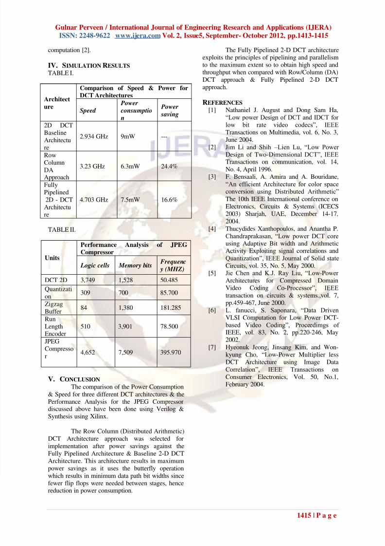
IV. SIMULATION RESULTS TABLE I.
Architect
ure
Comparison of Speed & Power for
DCT Architectures
Speed Power consumptio n
Power
saving
2D DCTBaseline
Architecture
2.934 GHz 9mW ---
RowColumn
DAApproach
3.23 GHz 6.3mW 24.4%
Fully
Pipelined2D - DCTArchitecture
4.703 GHz 7.5mW 16.6%
TABLE II.
Units
Performance Analysis of JPEG
Compressor
Logic cells Memory bits Frequenc
y (MHZ)
DCT 2D 3,749 1,528 50.485
Quantization
309 700 85.700
Zigzag
Buffer84 1,380 181.285
RunLengthEncoder
510 3,901 78.500
JPEGCompressor
4,652 7,509 395.970
V. CONCLUSION The comparison of the Power Consumption
& Speed for three different DCT architectures & thePerformance Analysis for the JPEG Compressordiscussed above have been done using Verilog &Synthesis using Xilinx.
The Row Column (Distributed Arithmetic)DCT Architecture approach was selected for
implementation after power savings against theFully Pipelined Architecture & Baseline 2-D DCTArchitecture. This architecture results in maximumpower savings as it uses the butterfly operation
which results in minimum data path bit widths sincefewer flip flops were needed between stages, hencereduction in power consumption.
The Fully Pipelined 2-D DCT architectureexploits the principles of pipelining and parallelismto the maximum extent so to obtain high speed andthroughput when compared with Row/Column (DA)
DCT approach & Fully Pipelined 2-D DCTapproach.
REFERENCES [1] Nathaniel J. August and Dong Sam Ha,
“Low power Design of DCT and IDCT for low bit rate video codecs”, IEEE
Transactions on Multimedia, vol. 6, No. 3,June 2004.
[2] Jim Li and Shih –Lien Lu, “Low Power
Design of Two-Dimensional DCT”, IEEETransactions on communication, vol. 14,
No. 4, April 1996.[3] F. Bensaali, A. Amira and A. Bouridane,
“An efficient Architecture for color space
conversion using Distributed Arithmetic”The 10th IEEE International conference onElectronics, Circuits & Systems (ICECS2003) Sharjah, UAE, December 14-17,
2004.[4] Thucydides Xanthopoulos, and Anantha P.
Chandraprakasan, “Low power DCT coreusing Adaptive Bit width and ArithmeticActivity Exploiting signal correlations andQuantization”, IEEE Journal of Solid state
Circuits, vol. 35, No. 5, May 2000.[5] Jie Chen and K.J. Ray Liu, “Low-Power
Architectures for Compressed Domain
Video Coding Co-Processor”, IEEEtransaction on circuits & systems.,vol. 7,pp.459-467, June 2000.
[6] L. fanucci, S. Saponara, “Data DrivenVLSI Computation for Low Power DCT- based Video Coding”, Proceedimgs of IEEE, vol. 83, No. 2, pp.220-246, May2002.
[7] Hyeonuk Jeong, Jinsang Kim, and Won-kyung Cho, “Low-Power Multiplier lessDCT Architecture using Image DataCorrelation”, IEEE Transactions on
Consumer Electronics, Vol. 50, No.1,
February 2004.