
Hustler Raptor General Service Manual · 117373 REV F Hustler® Raptor® General Service Manual 200...
45
117373 REV F Hustler ® Raptor ® General Service Manual 200 South Ridge Road Hesston, Kansas 67062
Transcript of Hustler Raptor General Service Manual · 117373 REV F Hustler® Raptor® General Service Manual 200...

117373 REV F
Hustler® Raptor®
General Service Manual
200 South Ridge RoadHesston, Kansas
67062
REV F 117373
The Engine Owner’s Manual provides information regarding the U.S. Environmental Protection Agency (EPA)and the California Emission Control Regulation of emission systems, maintenance and warranty.
Keep Engine Owner’s Manual with your unit. Should the Engine Owner’s Manual become damaged orillegible, replace immediately. Replacements may be ordered per the information found in the ProductInformation section of the owner’s manual.
Federal law and California State law prohibit the following acts or the causing thereof:1. The removal or rendering inoperative by any person other than for purposes of maintenance,
repair, replacement, of any device or element of design incorporated into any equipment for thepurposes of emissions control prior to or after its sales or delivery to the ultimate purchaser orwhile it is in use, or
2. The use of the equipment after such device or element of design has been removed or renderedinoperative by any person.
WARNINGWARNINGWARNING
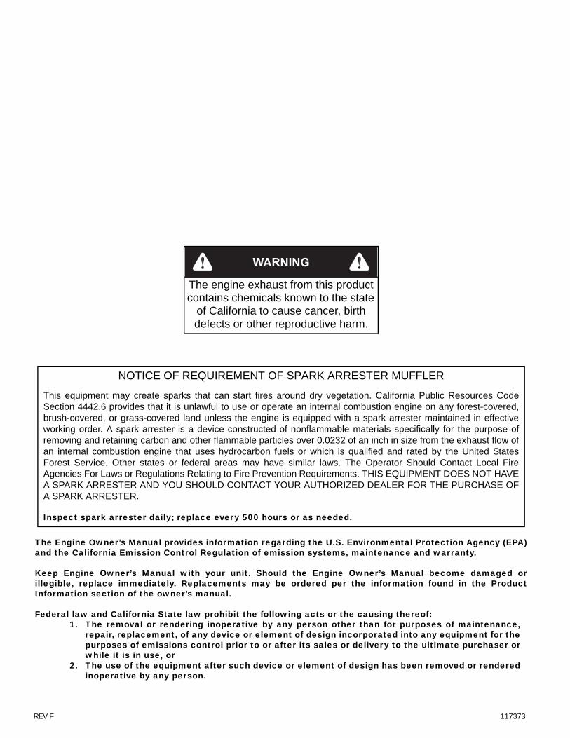
The engine exhaust from this product contains chemicals known to the state
of California to cause cancer, birth defects or other reproductive harm.
NOTICE OF REQUIREMENT OF SPARK ARRESTER MUFFLER
This equipment may create sparks that can start fires around dry vegetation. California Public Resources CodeSection 4442.6 provides that it is unlawful to use or operate an internal combustion engine on any forest-covered,brush-covered, or grass-covered land unless the engine is equipped with a spark arrester maintained in effectiveworking order. A spark arrester is a device constructed of nonflammable materials specifically for the purpose ofremoving and retaining carbon and other flammable particles over 0.0232 of an inch in size from the exhaust flow ofan internal combustion engine that uses hydrocarbon fuels or which is qualified and rated by the United StatesForest Service. Other states or federal areas may have similar laws. The Operator Should Contact Local FireAgencies For Laws or Regulations Relating to Fire Prevention Requirements. THIS EQUIPMENT DOES NOT HAVEA SPARK ARRESTER AND YOU SHOULD CONTACT YOUR AUTHORIZED DEALER FOR THE PURCHASE OFA SPARK ARRESTER.
Inspect spark arrester daily; replace every 500 hours or as needed.

117373 toc-1 REV F
Table of Contents
General Information . . . . . . . . . . . . . . . . . . . . . . . . . . . . . . . . . . . . . . . . . . . . . 1-1
Hustler® Service Program. . . . . . . . . . . . . . . . . . . . . . . . . . . . . . . . . . . . . 1-1Maintenance Introduction. . . . . . . . . . . . . . . . . . . . . . . . . . . . . . . . . . . . . 1-1Warranty . . . . . . . . . . . . . . . . . . . . . . . . . . . . . . . . . . . . . . . . . . . . . . . . . . . 1-1
Safety . . . . . . . . . . . . . . . . . . . . . . . . . . . . . . . . . . . . . . . . . . . . . . . . . . . . . . . . . 2-1
Safe Servicing Practices . . . . . . . . . . . . . . . . . . . . . . . . . . . . . . . . . . . . . . 2-1Pre-Operation Precautions . . . . . . . . . . . . . . . . . . . . . . . . . . . . . . . . . . . . 2-1Operation Precautions. . . . . . . . . . . . . . . . . . . . . . . . . . . . . . . . . . . . . . . . 2-2Operate Machine Safely . . . . . . . . . . . . . . . . . . . . . . . . . . . . . . . . . . . . . . 2-2General Maintenance Precautions. . . . . . . . . . . . . . . . . . . . . . . . . . . . . . 2-2Maintenance Precautions . . . . . . . . . . . . . . . . . . . . . . . . . . . . . . . . . . . . . 2-3
Torque . . . . . . . . . . . . . . . . . . . . . . . . . . . . . . . . . . . . . . . . . . . . . . . . . . . . . . . . 3-1
Standard Torques. . . . . . . . . . . . . . . . . . . . . . . . . . . . . . . . . . . . . . . . . . . . 3-1Special Torques . . . . . . . . . . . . . . . . . . . . . . . . . . . . . . . . . . . . . . . . . . . . . 3-1
Power Unit Maintenance . . . . . . . . . . . . . . . . . . . . . . . . . . . . . . . . . . . . . . . . . 4-1
Steering Adjustments . . . . . . . . . . . . . . . . . . . . . . . . . . . . . . . . . . . . . . . . 4-1Park Brake Spring Adjustment . . . . . . . . . . . . . . . . . . . . . . . . . . . . . . . . . 4-3Transaxle Drive Belt . . . . . . . . . . . . . . . . . . . . . . . . . . . . . . . . . . . . . . . . . . 4-4Tires . . . . . . . . . . . . . . . . . . . . . . . . . . . . . . . . . . . . . . . . . . . . . . . . . . . . . . . 4-6
Engine Maintenance. . . . . . . . . . . . . . . . . . . . . . . . . . . . . . . . . . . . . . . . . . . . . 5-1
General Engine Maintenance . . . . . . . . . . . . . . . . . . . . . . . . . . . . . . . . . . 5-1Engine Oil and Filter . . . . . . . . . . . . . . . . . . . . . . . . . . . . . . . . . . . . . . . . . 5-1Engine Air Filter . . . . . . . . . . . . . . . . . . . . . . . . . . . . . . . . . . . . . . . . . . . . . 5-1Carbon Canister . . . . . . . . . . . . . . . . . . . . . . . . . . . . . . . . . . . . . . . . . . . . . 5-2Fuel Evaporation System Filter . . . . . . . . . . . . . . . . . . . . . . . . . . . . . . . . 5-2Fuel and Evaporative System Line Routing . . . . . . . . . . . . . . . . . . . . . . 5-2Engine RPM Settings . . . . . . . . . . . . . . . . . . . . . . . . . . . . . . . . . . . . . . . . . 5-5
Deck Adjustments . . . . . . . . . . . . . . . . . . . . . . . . . . . . . . . . . . . . . . . . . . . . . . 6-1
Deck Leveling . . . . . . . . . . . . . . . . . . . . . . . . . . . . . . . . . . . . . . . . . . . . . . . 6-1Blades . . . . . . . . . . . . . . . . . . . . . . . . . . . . . . . . . . . . . . . . . . . . . . . . . . . . . 6-5Deck Belt . . . . . . . . . . . . . . . . . . . . . . . . . . . . . . . . . . . . . . . . . . . . . . . . . . . 6-736"/42" Deck Belt Routing. . . . . . . . . . . . . . . . . . . . . . . . . . . . . . . . . . . . 6-1052" Deck Belt Routing . . . . . . . . . . . . . . . . . . . . . . . . . . . . . . . . . . . . . . . 6-10

REV F toc-2 117373
Electrical . . . . . . . . . . . . . . . . . . . . . . . . . . . . . . . . . . . . . . . . . . . . . . . . . . . . . . 7-1
Electrical Schematic — Kawasaki. . . . . . . . . . . . . . . . . . . . . . . . . . . . . . . 7-1Electrical Schematic — Kawasaki. . . . . . . . . . . . . . . . . . . . . . . . . . . . . . . 7-2Electrical Schematic — Kohler . . . . . . . . . . . . . . . . . . . . . . . . . . . . . . . . . 7-3
Maintenance . . . . . . . . . . . . . . . . . . . . . . . . . . . . . . . . . . . . . . . . . . . . . . . . . . . 8-1
Maintenance Locator Chart. . . . . . . . . . . . . . . . . . . . . . . . . . . . . . . . . . . . 8-2
Troubleshooting . . . . . . . . . . . . . . . . . . . . . . . . . . . . . . . . . . . . . . . . . . . . . . . . 9-1
117373 1-1 REV F
GENERAL INFORMATION
Hustler® Service Program
This manual is part of a service package for the Hustler®
Raptor mowers. Use of this manual in conjunction with otherHustler® mower and component manuals will provide theinformation necessary to service and maintain the Hustler®
Raptor mower.
This General Service Manual is a service guide for use byService Technicians. It provides the necessary informationneeded to perform normal maintenance requirements onthese units.
The Parts Manual provides a complete parts listing for theunit. Use this manual when ordering parts.
The Operator's Manual provides fundamental operationalinformation and operational safety that is needed when oper-ating the mower.
The component manuals are furnished by the various man-ufacturers to be used for the troubleshooting and servicingof their components.
Maintenance Introduction
Regular maintenance is the best prevention for downtimeor premature failure. The following pages contain suggestedmaintenance information and schedules which the operator/mechanic should follow on a routine basis.
Remain alert for unusual noises, they could be signaling aproblem. Visually inspect the machine for any abnormal wearor damage. A good time to detect potential problems is whileperforming scheduled maintenance service. Correcting theproblem as quickly as possible is the best insurance.
Clear away heavy build-up of grease, oil and dirt, especiallyin the engine compartment and under the seat platform
areas; minute dust particles are abrasive to close-toleranceengine and hydraulic assemblies.
Daily inspect mower for grass clippings and wire and stringtangles. The underside of the mower deck will collect a build-up of grass clippings and dirt, especially when grass is wet orhas high moisture content. This build-up will harden, restrict-ing blade and air movement and will probably show a lesserquality of cut. Therefore it should be removed routinely.
To do this it will be necessary to raise and block the deck,using jack stands or blocks, in the full up position and scrapethe build-up from underneath.
Some repairs require the assistance of a trained servicemechanic and should not be attempted by unskilled person-nel. Consult your Hustler® Turf Equipment service centerwhen assistance is needed.
Information included in this manual was current at the timeof printing, but subsequent production changes may causeyour machine to vary slightly in detail. Hustler® Turf Equip-ment reserves the right to redesign and change the machineas deemed necessary, without notification. If a change hasbeen made to your machine which is not reflected in this ser-vice manual contact the Customer Service Department atHustler® Turf Equipment for additional information.
Warranty
Warranty repair must be performed by a Hustler® TurfEquipment Authorized Dealer before warranty credit can beallowed. Work performed by anyone other than an AuthorizedDealer will invalidate the warranty claim and warranty creditwill not be approved.

REV F 1-2 117373
117373 2-1 REV F
SAFETY
This safety alert symbol is used to call attention to a mes-sage intended to provide a reasonable degree of PERSONALSAFETY for operators and other persons during the normaloperation and servicing of this equipment.
Safe Servicing Practices
This product is capable of amputating hands and feet andthrowing objects. Always follow all safety instructions toavoid serious injury or death.
Understand correct service
Be sure you understand a service procedure beforeyou work on the machine.
Unauthorized modifications to the machine mayimpair the function and/or safety and affect machinelife.
If it is necessary to make checks with the engine run-ning, always use two people - with the operator at thecontrols, able to see the person doing the checking.
Pre-Operation Precautions
Fuel Handling To avoid personal injury or property damage, use
extreme care in handling fuel. Fuel is extremely flam-mable and the vapors are explosive.
Observe usual fuel handling precautions:
• Do not smoke while refueling. Extinguish all ciga-rettes, cigars, pipes and other sources of ignition.
• Do not remove fuel cap or fill tank with engine run-ning or while engine is hot. Clean up any fuel spills.
• Allow engine to cool before storing machineinside a building.
• Keep fuel away from open flame or spark andstore machine away from open flame or spark orpilot light such as on a water heater or appli-ances.
• Use extreme care when handling gasoline andother fuels. They are extremely flammable andvapors are explosive. A fire or explosion from fuelcan burn you and others and can damage prop-erty.
• Refuel outdoors. Never refuel or drain the fuelfrom the machine indoors.
• Never attempt to start engine when there is astrong odor of gasoline or diesel fuel fumes pres-ent. Locate and correct cause.
• Store fuel in an approved container and keep itout of the reach of children. Never buy more thana 30 day supply of fuel.
• Do not fill fuel containers inside a vehicle or on atruck or trailer bed with interior carpets or plastictruck bed liners. Always place fuel containers onthe ground away from your vehicle before filling.
• When practical, remove gas or diesel fuel pow-ered equipment from the truck or trailer andrefuel the equipment with its wheels on theground. If this is not possible, then refuel suchequipment on the truck or trailer using a portablecontainer and not a fuel dispenser nozzle. If afuel dispenser nozzle must be used, keep the noz-zle in contact with the rim of the fuel tank or con-tainer opening at all times until fueling iscomplete. Do not use a nozzle lock-open device.
• Never use gasoline or diesel fuel for cleaningparts.
• Read and observe safety precautions elsewherein this manual.
Gasoline and diesel fuel is harmful or fatal if swal-lowed.
• Long-term exposure to vapors can cause seriousinjury and illness.
• Avoid prolonged breathing of vapors.
• Keep face away from nozzle and gas tank or fuelcontainer opening.
• Keep fuel away from eyes and skin.
• If fuel is spilled on clothing, change clothingimmediately.
Understand Machine Operation Only qualified and trained personnel should operate
the equipment.
– denotes immediate hazards which WILL result insevere personal injury or death.
– denotes a hazard or unsafe practice whichCOULD result in severe personal injury or death.
DAN
GER
WAR
NIN
G
REV F 2-2 117373
Carefully read the operator’s manual and all manualsfurnished with the attachments. Learn the locationand purpose of all controls, instruments, indicatorsand labels.
Wear Protective Clothing
Do not operate or service the equipment while wearingsandals, tennis shoes, sneakers, shorts or any type ofloose fitting clothing. Long hair, loose clothing or jew-elry may get tangled in moving parts. Always wearlong pants, safety glasses, ear protection and safetyshoes when operating or servicing this machine.
Always wear adequate eye protection when servicingthe hydraulic system and battery, or when grindingmower blades and removing accumulated debris.
Prolonged exposure to loud noise can cause impair-ment or loss of hearing.
• Always wear adequate ear protection, such asearplugs, when operating this equipment as pro-longed exposure to uncomfortable or loud noisescan cause impairment or loss of hearing.
• Do not wear radios or music headphones whileoperating the machinery. Safe operation requiresyour full attention.
Operation Precautions
Avoid Fire Hazards Clean flammable material from machine. Prevent fires by
keeping engine compartment, top of deck, exhaust area,battery, hydraulic lines, fuel line, fuel tank and operator’sstation clean of accumulated trash, grass clippings, andother debris. Always clean up spilled fuel and oil.
Start Engine Safely Avoid possible injury or death from machine runaway.
Do not start engine by shorting across starter termi-nals.
Before you start the engine:
• Sit on the operator’s seat.
• Move control levers to the neutral/brake position.
Operate Machine Safely
Refer to the unit’s operator’s manual for completesafety information on safe machine operation.
Always maintain a safe distance from people and petswhen mowing
Always be aware of what is behind the machine beforebacking up.
Never leave machine unattended with ignition key inswitch, especially with children present.
Follow daily and weekly checklists, making sure hosesare tightly secured and bolts are tightened.
Always keep engine and machine clean, removingaccumulated dirt, trash and other material frommachine.
Never put hands or feet under any part of the machinewhile it is running.
Never attempt to start engine when there is a strongodor of gasoline fumes present. Locate and correctcause.
Keep all safety shields and covers in place, except forservicing.
Do not touch hot parts of machine.
General Maintenance Precautions
Repairs or maintenance requiring engine power shouldbe performed by trained maintenance personnel only.
Never run the engine in an enclosed area unlessexhaust is vented to the outside. Exhaust gases con-tain carbon monoxide which is an odorless and deadlypoison.
Unless specifically required, DO NOT have engine run-ning when servicing or making adjustments to mower.Park the machine on level ground. Place steering con-trol levers in the park brake position, disengage deckclutch, lower deck, remove ignition switch key and dis-connect negative battery cable before doing any main-tenance. Wait for all movement to stop beforeadjusting, cleaning or repairing. To prevent carbonmonoxide poisoning, be sure proper ventilation isavailable when engine must be operated in anenclosed area.
Before working on or under the deck, make certainengine cannot be accidentally started. Shut engine off,remove ignition switch key and disconnect negativebattery cable for maximum safety.
Except when changing or checking belt, always keepbelt covers on mower deck for safety as well as clean-liness.
Use a stick or similar instrument to clean under themower making sure that no part of the body, especiallyarms and hands are under mower.
Keep your machine clean and remove any deposits oftrash and clippings, which can cause engine fires andhydraulic overheating as well as excessive belt wear.Clean up oil or fuel spillage. Allow machine to coolbefore storing.
Always wear adequate eye protection when servicingthe hydraulic system and battery, or when grindingmower blades and removing accumulated debris.
Never attempt to make any adjustments or repairs tothe mower drive system, mower deck or any attach-ment while the engine is running or deck clutch isengaged.
Exercise caution when releasing spring tension fromany of the belt idlers or when working with any of thedeck lift components.
117373 2-3 REV F
Never work under the machine or attachment unless itis safely supported with jack stands. Make certainmachine is secure when it is raised and placed on thejack stands. The jack stands should not allow themachine to move when the engine is running and thedrive wheels are rotating. Use only certified jack stands.Use only appropriate jack stands, with a minimumweight rating of 2000 pounds to block the unit up. Usein pairs only. Follow the instructions supplied with thevehicle stands.
Keep nuts and bolts tight, especially the blade attach-ment bolts. Keep equipment in good working condi-tion.
Never tamper with safety devices. Check their properoperation regularly.
Exercise caution when working under the deck as themower blades are extremely sharp. Wrap the blade(s)or wear gloves and use extra caution when servicingthem.
Use only genuine Hustler® replacement parts to ensurethat original standards are maintained.
Maintenance Precautions
Avoid Fire Hazards Be prepared if an accident or fire should occur. Know
where the first aid kit and the fire extinguishers arelocated and how to use them.
Provide adequate ventilation when charging batteries.
Do not smoke near battery.
Never check fuel level with an open flame.
Never use an open flame to look for leaks anywhere onthe equipment.
Never use an open flame as light anywhere on oraround the equipment.
When preparing engine for storage, remember that fuelstabilizer is volatile and therefore dangerous. Seal andtape openings after adding the inhibitor. Keep con-tainer tightly closed when not in use.
Inspect electrical wiring for worn or frayed insulation.Install new wiring if wires are damaged.
Prepare For Emergencies Be prepared if a fire starts.
Keep a first aid kit and fire extinguishers available.
Keep emergency numbers for doctor, ambulance ser-vice, hospital, and fire department near the telephone.
Prevent Battery Explosions Battery posts, terminals, and related accessories con-
tain lead and lead compounds, chemicals known to theState of California to cause cancer and reproductiveharm. Wash hands after handling.
Charge batteries in an open well-ventilated area, awayfrom sparks and flames. Unplug charger before con-necting or disconnecting from battery. Wear protectiveclothing and use insulated tools.
Avoid skin and clothing contact with battery acid.
• Always wear eye protection when checking thebattery, acid can cause serious injury to skin andeyes. If contact occurs, flush area with cleanwater and call physician immediately. Acid willalso damage clothing.
• Do not drink the battery electrolyte.
• Do not allow open flame near the battery whencharging.
• Hydrogen gas forms inside the battery. This gasis both toxic and flammable and may cause anexplosion if exposed to flame. Always disconnectthe negative (black) battery cable(s) before dis-connecting the positive (red) cable(s). Alwaysconnect the positive (red) battery cable(s) beforeconnecting the negative (black) cable(s).
• Do not overfill battery.
• Electrolyte may overflow and damage paint, wir-ing or structure. When cleaning the battery, usesoap and water. Be careful not to get soap andwater into the battery. Clean the battery termi-nals with a solution of four parts water and onepart baking soda when they become corroded.
Shorts caused by battery terminals or metal toolstouching metal mower components can cause sparks.Sparks can cause a battery gas explosion which willresult in personal injury.
• Prevent the battery terminals from touching anymetal mower parts when removing or installingthe battery.
• Do not allow metal tools to short between thebattery terminals and metal mower parts.
Incorrect battery cable routing could cause damage tothe mower and battery cables. This can cause sparkswhich can cause a battery gas explosion which willresult in personal injury. Always disconnect the nega-tive (black) battery cable(s) before disconnecting thepositive (red) cable(s). Always connect the positive(red) battery cable(s) before connecting the negative(black) cable(s).
Avoid Acid Burns Sulfuric acid in battery electrolyte is poisonous. It is
strong enough to burn skin, eat holes in clothing andcause blindness if splashed in eyes.
Avoid the hazard by:
• Filling batteries in a well-ventilated area.
• Wearing eye protection and rubber gloves.
• Avoiding breathing fumes when electrolyte isadded.

REV F 2-4 117373
• Avoiding spilling or dripped electrolyte.
If you spill acid on yourself:
• Flush your skin with water.
• Apply baking soda or lime to help neutralize theacid.
• Flush your eyes with water for 10-15 minutes. Getmedical attention immediately.
If acid is swallowed:
• Drink large amounts of water or milk.
• Then drink milk of magnesia, beaten eggs or veg-etable oil.
• Get medical attention immediately.
117373 3-1 REV F
TORQUE
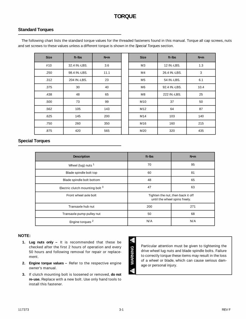
Standard Torques
The following chart lists the standard torque values for the threaded fasteners found in this manual. Torque all cap screws, nutsand set screws to these values unless a different torque is shown in the Special Torques section.
Special Torques
NOTE:
1. Lug nuts only – It is recommended that these bechecked after the first 2 hours of operation and every50 hours and following removal for repair or replace-ment.
2. Engine torque values – Refer to the respective engineowner’s manual.
3. If clutch mounting bolt is loosened or removed, do notre-use. Replace with a new bolt. Use only hand tools toinstall this fastener.
Size ft-lbs N•m Size ft-lbs N•m
#10 32.4 IN.-LBS. 3.6 M3 12 IN.-LBS. 1.3
.250 98.4 IN.-LBS. 11.1 M4 26.4 IN.-LBS. 3
.312 204 IN.-LBS. 23 M5 54 IN.-LBS. 6.1
.375 30 40 M6 92.4 IN.-LBS. 10.4
.438 48 65 M8 222 IN.-LBS. 25
.500 73 99 M10 37 50
.562 105 143 M12 64 87
.625 145 200 M14 103 140
.750 260 350 M16 160 215
.875 420 565 M20 320 435
Description ft-lbs N•m
Wheel (lug) nuts 1 70 95
Blade spindle bolt top 60 81
Blade spindle bolt bottom 48 65
Electric clutch mounting bolt 3 47 63
Front wheel axle bolt Tighten the nut, then back it off until the wheel spins freely.
Transaxle hub nut 200 271
Transaxle pump pulley nut 50 68
Engine torques 2 N/A N/A
Particular attention must be given to tightening thedrive wheel lug nuts and blade spindle bolts. Failureto correctly torque these items may result in the lossof a wheel or blade, which can cause serious dam-age or personal injury.W
ARN
ING

REV F 3-2 117373
117373 4-1 REV F
POWER UNIT MAINTENANCE
Steering Adjustments
Steering control lever neutral adjustment The mower’s steering has been factory adjusted to elimi-
nate creeping when the steering control levers are in the neu-tral position. However, should the mower begin to creep, thesteering control lever linkage can be adjusted.
Before considering any adjustment, check the tire air pres-sure. Unequal tire pressure will cause the mower to drift toone side. Refer to tire pressure information in the Tire sectionfor detailed information.
NOTE: Proper park brake adjustment must be completedbefore the steering control lever neutral adjustment can bedone. Refer to the Park Brake Spring Adjustment section fordetailed information.
Fine adjustment to the unit’s steering is made with thetransmission’s control rod.
Neutral is properly adjusted when the steering controllevers are in the park brake position and the transmissionsdo not “whine”.
If this occurs, the steering control linkage may be adjustedas follows:
1. Shut engine off, place steering control levers in thepark brake position, disengage deck clutch, removeignition switch key and disconnect negative batterycable before doing any adjustments.
2. Raise the rear of the mower and block with certifiedjack stands. Remove the rear wheels.
3. Chock the front tires.
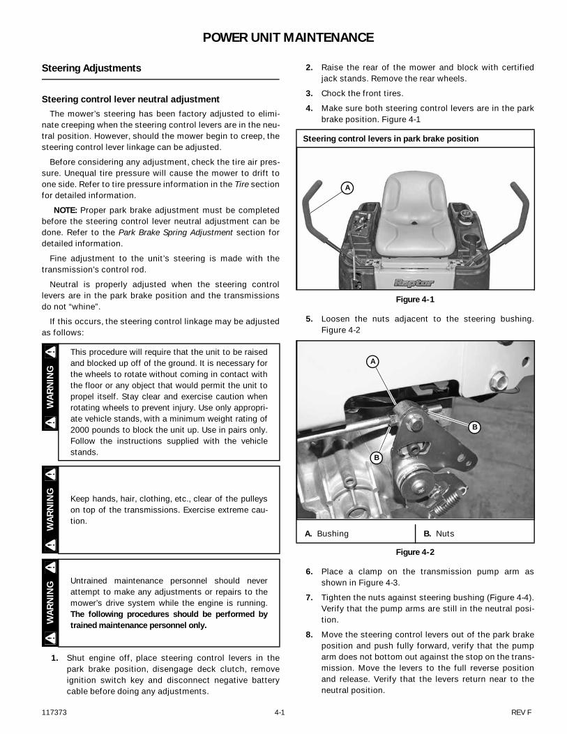
4. Make sure both steering control levers are in the parkbrake position. Figure 4-1
5. Loosen the nuts adjacent to the steering bushing.Figure 4-2
6. Place a clamp on the transmission pump arm asshown in Figure 4-3.
7. Tighten the nuts against steering bushing (Figure 4-4).Verify that the pump arms are still in the neutral posi-tion.
8. Move the steering control levers out of the park brakeposition and push fully forward, verify that the pumparm does not bottom out against the stop on the trans-mission. Move the levers to the full reverse positionand release. Verify that the levers return near to theneutral position.
This procedure will require that the unit to be raisedand blocked up off of the ground. It is necessary forthe wheels to rotate without coming in contact withthe floor or any object that would permit the unit topropel itself. Stay clear and exercise caution whenrotating wheels to prevent injury. Use only appropri-ate vehicle stands, with a minimum weight rating of2000 pounds to block the unit up. Use in pairs only.Follow the instructions supplied with the vehiclestands.
Keep hands, hair, clothing, etc., clear of the pulleyson top of the transmissions. Exercise extreme cau-tion.
Untrained maintenance personnel should neverattempt to make any adjustments or repairs to themower’s drive system while the engine is running.The following procedures should be performed bytrained maintenance personnel only.
WAR
NIN
GW
ARN
ING
WAR
NIN
G
Steering control levers in park brake position
Figure 4-1
A. Bushing B. Nuts
Figure 4-2
A
A
B
B
REV F 4-2 117373
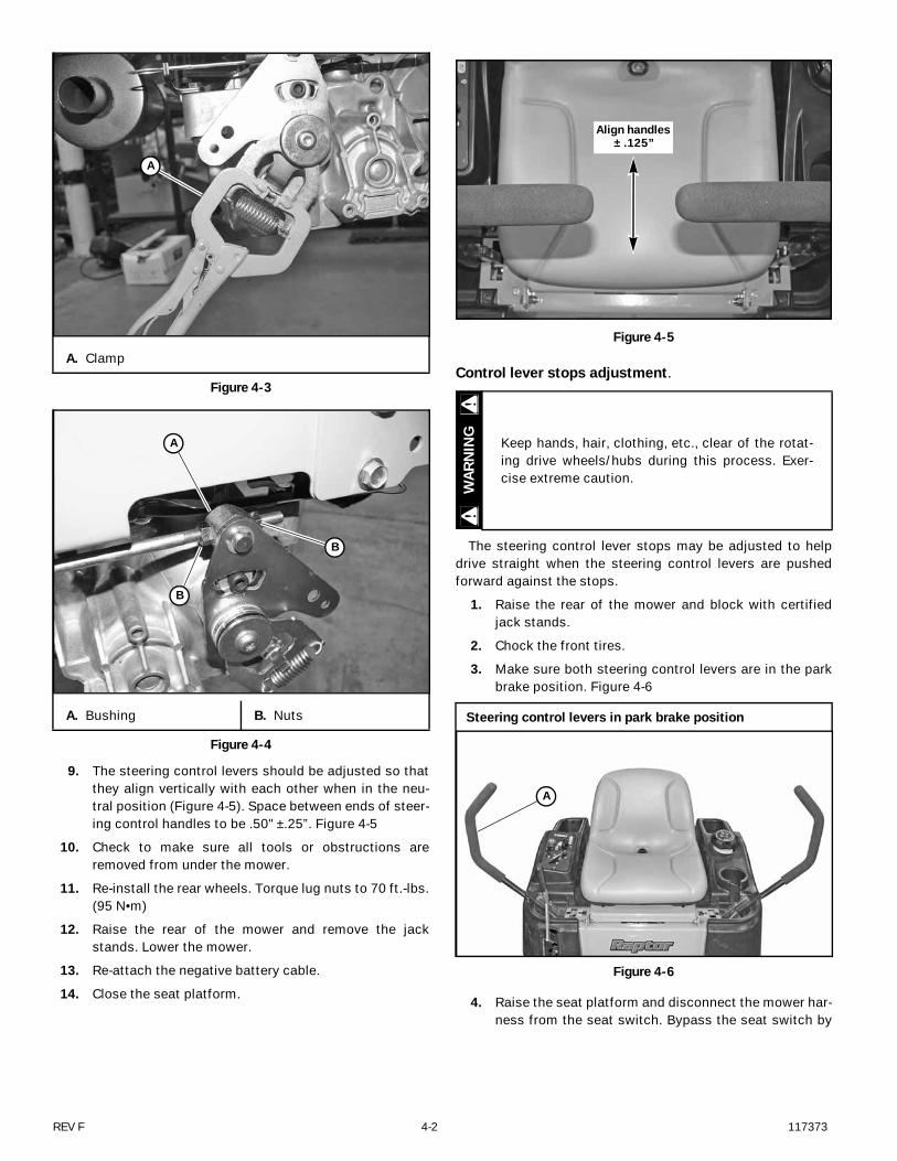
9. The steering control levers should be adjusted so thatthey align vertically with each other when in the neu-tral position (Figure 4-5). Space between ends of steer-ing control handles to be .50" ±.25”. Figure 4-5
10. Check to make sure all tools or obstructions areremoved from under the mower.
11. Re-install the rear wheels. Torque lug nuts to 70 ft.-lbs.(95 N•m)
12. Raise the rear of the mower and remove the jackstands. Lower the mower.
13. Re-attach the negative battery cable.
14. Close the seat platform.
Control lever stops adjustment.
The steering control lever stops may be adjusted to helpdrive straight when the steering control levers are pushedforward against the stops.
1. Raise the rear of the mower and block with certifiedjack stands.
2. Chock the front tires.
3. Make sure both steering control levers are in the parkbrake position. Figure 4-6
4. Raise the seat platform and disconnect the mower har-ness from the seat switch. Bypass the seat switch by
A. Clamp
Figure 4-3
A. Bushing B. Nuts
Figure 4-4
A
A
B
B
Figure 4-5
Keep hands, hair, clothing, etc., clear of the rotat-ing drive wheels/hubs during this process. Exer-cise extreme caution.
Steering control levers in park brake position
Figure 4-6
Align handles ± .125”
WAR
NIN
G
A
117373 4-3 REV F
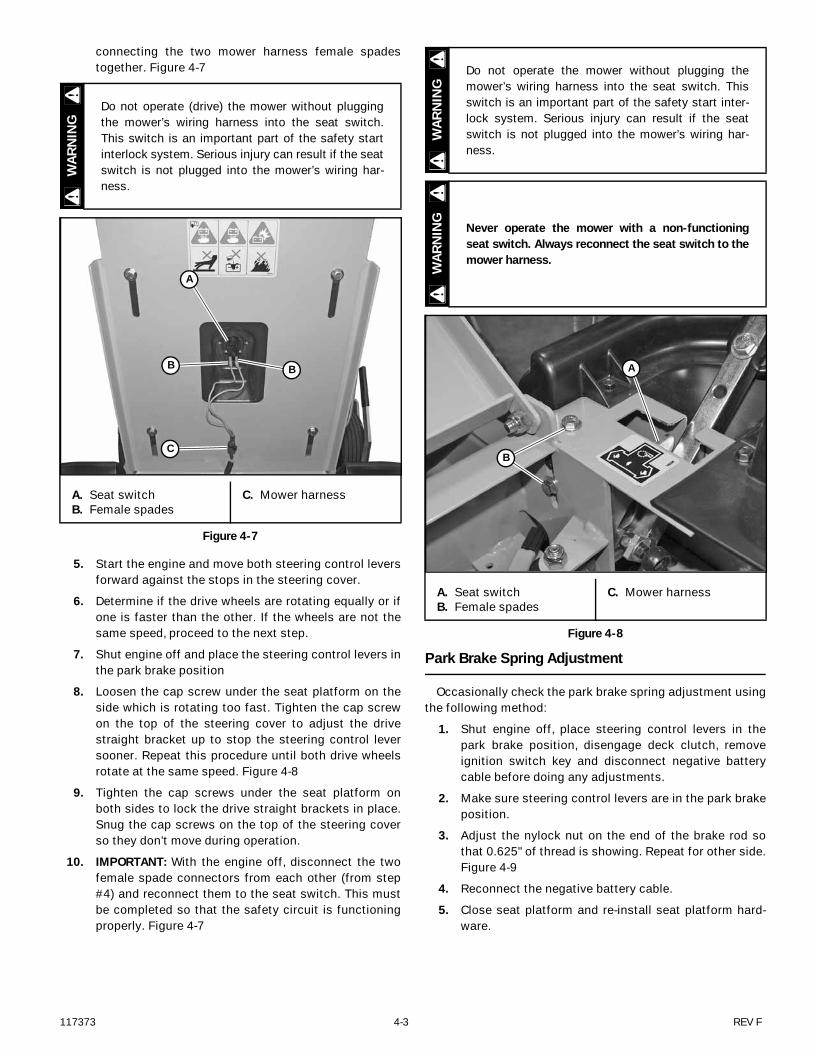
connecting the two mower harness female spadestogether. Figure 4-7
5. Start the engine and move both steering control leversforward against the stops in the steering cover.
6. Determine if the drive wheels are rotating equally or ifone is faster than the other. If the wheels are not thesame speed, proceed to the next step.
7. Shut engine off and place the steering control levers inthe park brake position
8. Loosen the cap screw under the seat platform on theside which is rotating too fast. Tighten the cap screwon the top of the steering cover to adjust the drivestraight bracket up to stop the steering control leversooner. Repeat this procedure until both drive wheelsrotate at the same speed. Figure 4-8
9. Tighten the cap screws under the seat platform onboth sides to lock the drive straight brackets in place.Snug the cap screws on the top of the steering coverso they don't move during operation.
10. IMPORTANT: With the engine off, disconnect the twofemale spade connectors from each other (from step#4) and reconnect them to the seat switch. This mustbe completed so that the safety circuit is functioningproperly. Figure 4-7
Park Brake Spring Adjustment
Occasionally check the park brake spring adjustment usingthe following method:
1. Shut engine off, place steering control levers in thepark brake position, disengage deck clutch, removeignition switch key and disconnect negative batterycable before doing any adjustments.
2. Make sure steering control levers are in the park brakeposition.
3. Adjust the nylock nut on the end of the brake rod sothat 0.625" of thread is showing. Repeat for other side.Figure 4-9
4. Reconnect the negative battery cable.
5. Close seat platform and re-install seat platform hard-ware.
Do not operate (drive) the mower without pluggingthe mower’s wiring harness into the seat switch.This switch is an important part of the safety startinterlock system. Serious injury can result if the seatswitch is not plugged into the mower’s wiring har-ness.
A. Seat switchB. Female spades
C. Mower harness
Figure 4-7
WAR
NIN
G
A
BB
C
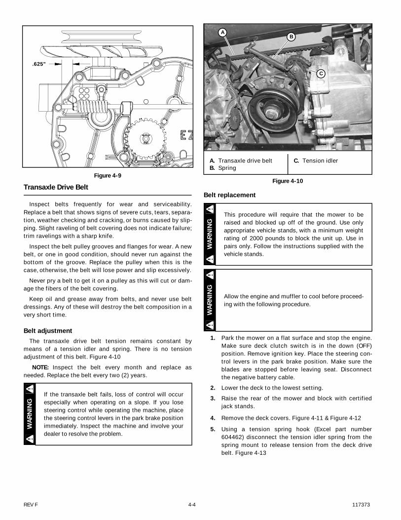
Do not operate the mower without plugging themower’s wiring harness into the seat switch. Thisswitch is an important part of the safety start inter-lock system. Serious injury can result if the seatswitch is not plugged into the mower’s wiring har-ness.
Never operate the mower with a non-functioningseat switch. Always reconnect the seat switch to themower harness.
A. Seat switchB. Female spades
C. Mower harness
Figure 4-8
WAR
NIN
GW
ARN
ING
A
B
REV F 4-4 117373
Transaxle Drive Belt
Inspect belts frequently for wear and serviceability.Replace a belt that shows signs of severe cuts, tears, separa-tion, weather checking and cracking, or burns caused by slip-ping. Slight raveling of belt covering does not indicate failure;trim ravelings with a sharp knife.
Inspect the belt pulley grooves and flanges for wear. A newbelt, or one in good condition, should never run against thebottom of the groove. Replace the pulley when this is thecase, otherwise, the belt will lose power and slip excessively.
Never pry a belt to get it on a pulley as this will cut or dam-age the fibers of the belt covering.
Keep oil and grease away from belts, and never use beltdressings. Any of these will destroy the belt composition in avery short time.
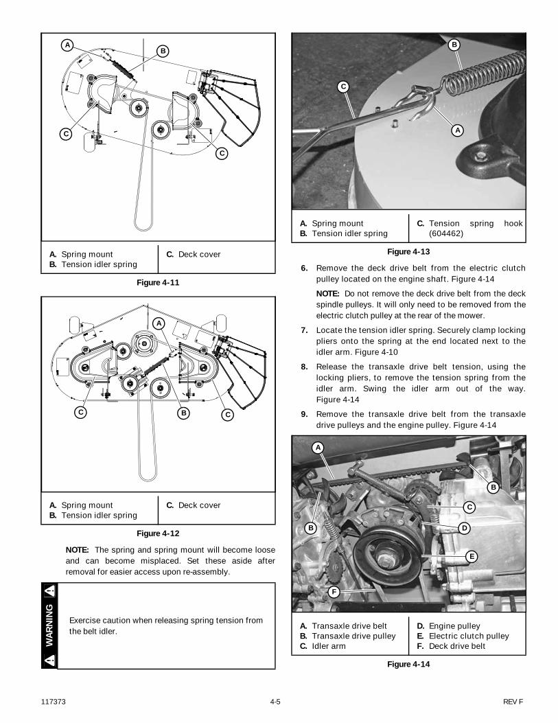
Belt adjustmentThe transaxle drive belt tension remains constant by
means of a tension idler and spring. There is no tensionadjustment of this belt. Figure 4-10
NOTE: Inspect the belt every month and replace asneeded. Replace the belt every two (2) years.
Belt replacement
1. Park the mower on a flat surface and stop the engine.Make sure deck clutch switch is in the down (OFF)position. Remove ignition key. Place the steering con-trol levers in the park brake position. Make sure theblades are stopped before leaving seat. Disconnectthe negative battery cable.
2. Lower the deck to the lowest setting.
3. Raise the rear of the mower and block with certifiedjack stands.
4. Remove the deck covers. Figure 4-11 & Figure 4-12
5. Using a tension spring hook (Excel part number604462) disconnect the tension idler spring from thespring mount to release tension from the deck drivebelt. Figure 4-13
Figure 4-9
If the transaxle belt fails, loss of control will occurespecially when operating on a slope. If you losesteering control while operating the machine, placethe steering control levers in the park brake positionimmediately. Inspect the machine and involve yourdealer to resolve the problem.
.625"
WAR
NIN
G
A. Transaxle drive beltB. Spring
C. Tension idler
Figure 4-10
This procedure will require that the mower to beraised and blocked up off of the ground. Use onlyappropriate vehicle stands, with a minimum weightrating of 2000 pounds to block the unit up. Use inpairs only. Follow the instructions supplied with thevehicle stands.
Allow the engine and muffler to cool before proceed-ing with the following procedure.
AB
C
WAR
NIN
GW
ARN
ING
117373 4-5 REV F
NOTE: The spring and spring mount will become looseand can become misplaced. Set these aside afterremoval for easier access upon re-assembly.
6. Remove the deck drive belt from the electric clutchpulley located on the engine shaft. Figure 4-14
NOTE: Do not remove the deck drive belt from the deckspindle pulleys. It will only need to be removed from theelectric clutch pulley at the rear of the mower.
7. Locate the tension idler spring. Securely clamp lockingpliers onto the spring at the end located next to theidler arm. Figure 4-10
8. Release the transaxle drive belt tension, using thelocking pliers, to remove the tension spring from theidler arm. Swing the idler arm out of the way.Figure 4-14
9. Remove the transaxle drive belt from the transaxledrive pulleys and the engine pulley. Figure 4-14
A. Spring mountB. Tension idler spring
C. Deck cover
Figure 4-11
A. Spring mountB. Tension idler spring
C. Deck cover
Figure 4-12
Exercise caution when releasing spring tension fromthe belt idler.
AB
C
C
A
B CC
WAR
NIN
G
A. Spring mountB. Tension idler spring
C. Tension spring hook(604462)
Figure 4-13
A. Transaxle drive beltB. Transaxle drive pulleyC. Idler arm
D. Engine pulleyE. Electric clutch pulleyF. Deck drive belt
Figure 4-14
C
B
A
A
B
C
D
E
B
F
REV F 4-6 117373
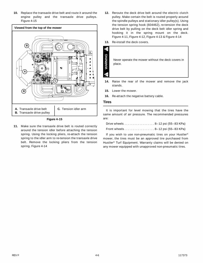
10. Replace the transaxle drive belt and route it around theengine pulley and the transaxle drive pulleys.Figure 4-15
11. Make sure the transaxle drive belt is routed correctlyaround the tension idler before attaching the tensionspring. Using the locking pliers, re-attach the tensionspring to the idler arm to re-tension the transaxle drivebelt. Remove the locking pliers from the tensionspring. Figure 4-14
12. Reroute the deck drive belt around the electric clutchpulley. Make certain the belt is routed properly aroundthe spindle pulleys and stationary idler pulley(s). Usingthe tension spring hook (604462), re-tension the deckdrive belt by pulling on the deck belt idler spring andhooking it in the spring mount on the deck.Figure 4-11, Figure 4-12, Figure 4-13 & Figure 4-14
13. Re-install the deck covers.
14. Raise the rear of the mower and remove the jackstands.
15. Lower the mower.
16. Re-attach the negative battery cable.
Tires
It is important for level mowing that the tires have thesame amount of air pressure. The recommended pressuresare:
Drive wheels . . . . . . . . . . . . . . . . . . 8–12 psi (55–83 KPa)
Front wheels . . . . . . . . . . . . . . . . . . 8–12 psi (55–83 KPa)
If you wish to use non-pneumatic tires on your Hustler®
mower, the tires must be an approved tire purchased fromHustler® Turf Equipment. Warranty claims will be denied onany mower equipped with unapproved non-pneumatic tires.
Viewed from the top of the mower
A. Transaxle drive beltB. Transaxle drive pulley
C. Tension idler arm
Figure 4-15
B
B
C
A
Never operate the mower without the deck covers inplace.
WAR
NIN
G
117373 5-1 REV F
ENGINE MAINTENANCE
General Engine Maintenance
Detailed instructions and recommendations for break-inand regular maintenance are specified in the Engine Owner’sManual. Please refer to this manual for engine servicing,lubricating oil levels with quality and viscosity recommenda-tions, bolt torques, etc. The engine warranty is backed by themanufacturer. Special attention should be paid to applicabledata which will not be duplicated here.
Engine Oil and Filter
Check engine oil daily and after every 4 hours of operation.Mower must be on a level surface when checking oil. Refer toengine manual and maintenance schedule for oil recommen-dation and capacities.
Change the engine oil and filter after the first 5 hours ofoperation and then per the engine manufacturer’s recommen-dations after that. If mower is being operated in extremelydirty conditions, then it is recommended oil be changed morefrequently.
IMPORTANT: After the new oil filter has been installed,clean up any oil which may have spilled onto the engineplate, muffler, and heat shield.
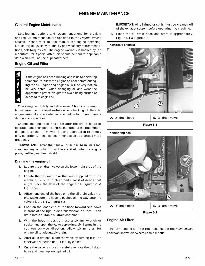
Draining the engine oil: 1. Locate the oil drain valve on the lower right side of the
engine.
2. Locate the oil drain hose that was supplied with themachine. Be sure to clean and clear it of debris thatmight block the flow of the engine oil. Figure 5-1 &Figure 5-2
3. Attach one end of the hose onto the oil drain valve nip-ple. Make sure the hose is pushed all the way onto thevalve. Figure 5-1 & Figure 5-2
4. Position the loose end of the hose forward and downin front of the right side transmission so that it candrain into a suitable oil drain container.
5. With the hose in position, use a 10 mm wrench orsocket and open the valve approximately 4 turns in thecounterclockwise direction. Allow 10 minutes forengine oil to adequately drain.
6. After oil is drained, close the valve by turning it in theclockwise direction until it is fully closed.
7. Once the valve is closed, carefully remove the oil drainhose and clean up any spilled oil.
IMPORTANT: All oil drips or spills must be cleaned offof the exhaust system before operating the machine.
8. Clean the oil drain hose and store it appropriately.Figure 5-1 & Figure 5-2
Engine Air Filter
Perform engine air filter maintenance per the MaintenanceSchedule shown elsewhere in this manual.
If the engine has been running and is up to operatingtemperature, allow the engine to cool before chang-ing the oil. Engine and engine oil will be very hot, sobe very careful when changing oil and wear theappropriate protective gear to avoid being burned orexposed to engine oil.
WAR
NIN
G
Kawasaki engines
A. Oil drain hose B. Oil drain valve
Figure 5-1
Kohler engines
A. Oil drain hose B. Oil drain valve
Figure 5-2
AB
AB
REV F 5-2 117373
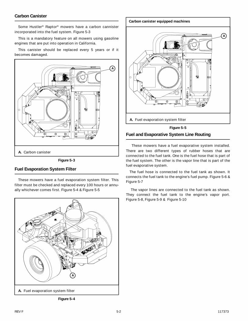
Carbon Canister
Some Hustler® Raptor® mowers have a carbon cannisterincorporated into the fuel system. Figure 5-3
This is a mandatory feature on all mowers using gasolineengines that are put into operation in California.
This canister should be replaced every 5 years or if itbecomes damaged.
Fuel Evaporation System Filter
These mowers have a fuel evaporation system filter. Thisfilter must be checked and replaced every 100 hours or annu-ally whichever comes first. Figure 5-4 & Figure 5-5
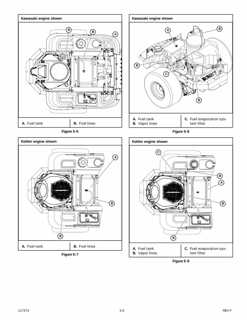
Fuel and Evaporative System Line Routing
These mowers have a fuel evaporative system installed.There are two different types of rubber hoses that areconnected to the fuel tank. One is the fuel hose that is part ofthe fuel system. The other is the vapor line that is part of thefuel evaporative system.
The fuel hose is connected to the fuel tank as shown. Itconnects the fuel tank to the engine’s fuel pump. Figure 5-6 &Figure 5-7
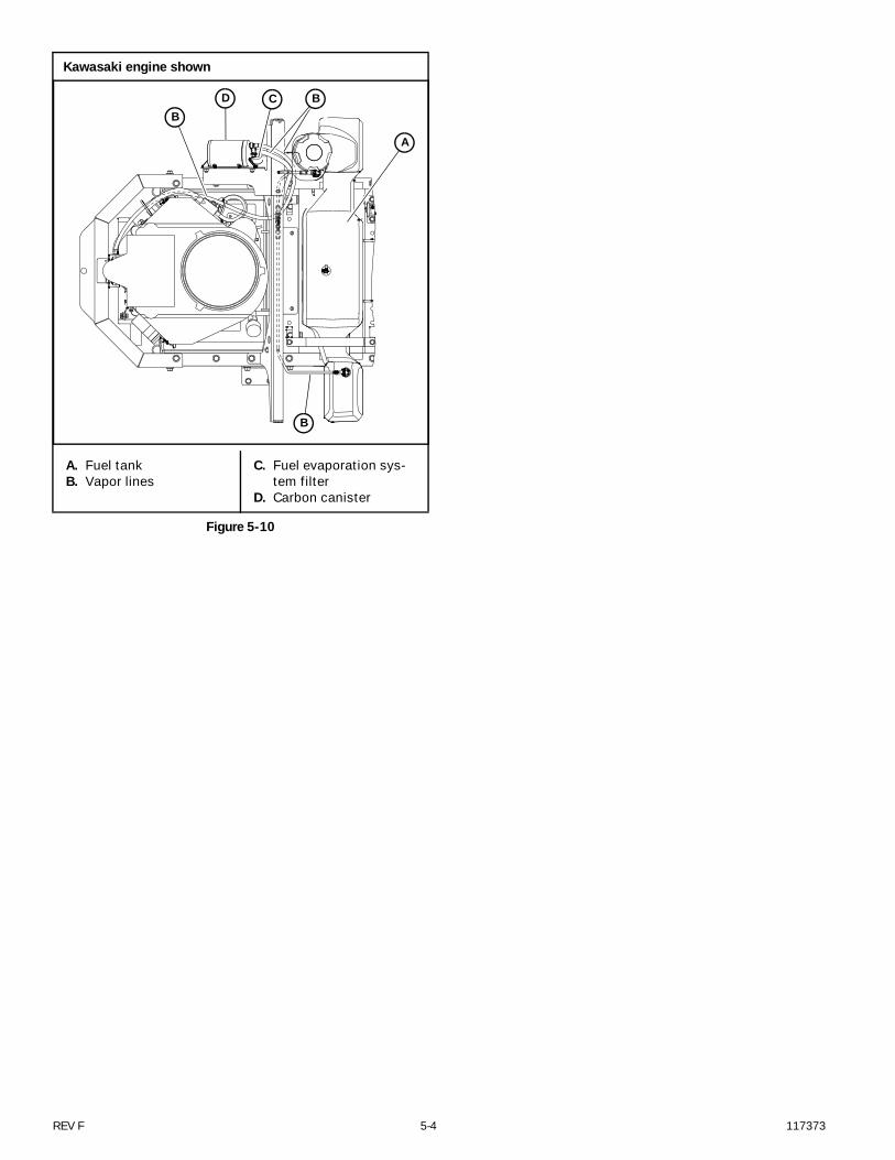
The vapor lines are connected to the fuel tank as shown.They connect the fuel tank to the engine’s vapor port.Figure 5-8, Figure 5-9 & Figure 5-10
A. Carbon canister
Figure 5-3
A. Fuel evaporation system filter
Figure 5-4
A
A
Carbon canister equipped machines
A. Fuel evaporation system filter
Figure 5-5
A
117373 5-3 REV F
Kawasaki engine shown
A. Fuel tank B. Fuel lines
Figure 5-6
Kohler engine shown
A. Fuel tank B. Fuel lines
Figure 5-7
ABB
A
B
B
Kawasaki engine shown
A. Fuel tankB. Vapor lines
C. Fuel evaporation sys-tem filter
Figure 5-8
Kohler engine shown
A. Fuel tankB. Vapor lines
C. Fuel evaporation sys-tem filter
Figure 5-9
B
B
C
A
B
A
B
B
B
C
REV F 5-4 117373
Kawasaki engine shown
A. Fuel tankB. Vapor lines
C. Fuel evaporation sys-tem filter
D. Carbon canister
Figure 5-10
A
B
B
BCD

117373 5-5 REV F
Engine RPM Settings
The engine rpm’s are set at the factory for maximum mowing efficiency. Occasionally it may be necessary to check and adjust thesettings. The idle speeds should be set as follows:
NOTE: Model numbers may or may not end with an extension after the number. There are several different extensions that may beshown; i.e. EX or CE.
Example: 922222 (no extension)
922222 EX
922222 CE
922222 US
Kawasaki FR651 / FR691
ENGINE SPEED
MODEL NO. ENDING WITH: HIGH IDLE
Model NO. without extensionModel NO. with US extensionModel NO. with EX extension
3200 ± 50 rpm
Kawasaki FR541
ENGINE SPEED
MODEL NO. ENDING WITH: HIGH IDLE
Model NO. without extension Model NO. with US extensionModel NO. with EX extension
3200 ± 50 rpm
Model NO. with CE extension 2450 ± 50 rpm
Kohler KT725 / KT735
ENGINE SPEED
MODEL NO. ENDING WITH: HIGH IDLE
Model NO. without extension Model NO. with US extensionModel NO. with EX extension
3200 ± 50 rpm
Model NO. with CE extension 2450 ± 50 rpm

REV F 5-6 117373
117373 6-1 REV F
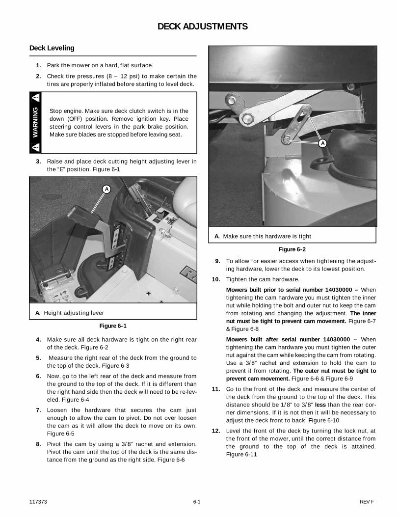
DECK ADJUSTMENTS
Deck Leveling
1. Park the mower on a hard, flat surface.
2. Check tire pressures (8 – 12 psi) to make certain thetires are properly inflated before starting to level deck.
3. Raise and place deck cutting height adjusting lever inthe “E” position. Figure 6-1
4. Make sure all deck hardware is tight on the right rearof the deck. Figure 6-2
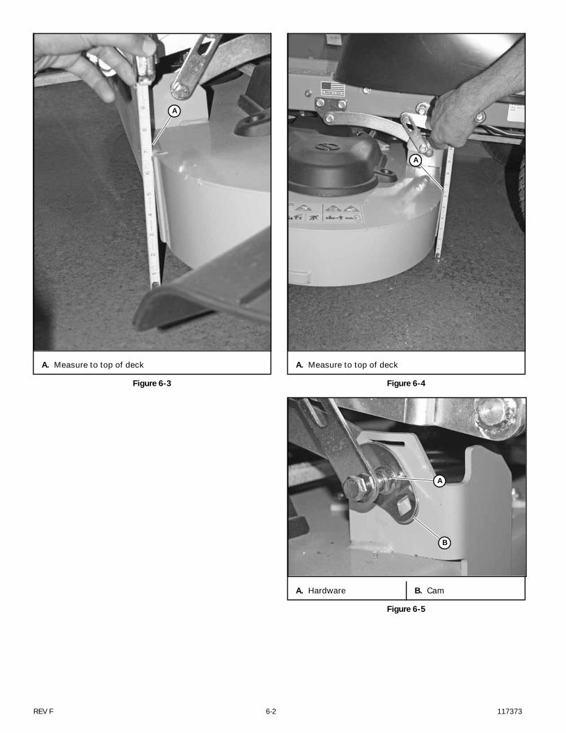
5. Measure the right rear of the deck from the ground tothe top of the deck. Figure 6-3
6. Now, go to the left rear of the deck and measure fromthe ground to the top of the deck. If it is different thanthe right hand side then the deck will need to be re-lev-eled. Figure 6-4
7. Loosen the hardware that secures the cam justenough to allow the cam to pivot. Do not over loosenthe cam as it will allow the deck to move on its own.Figure 6-5
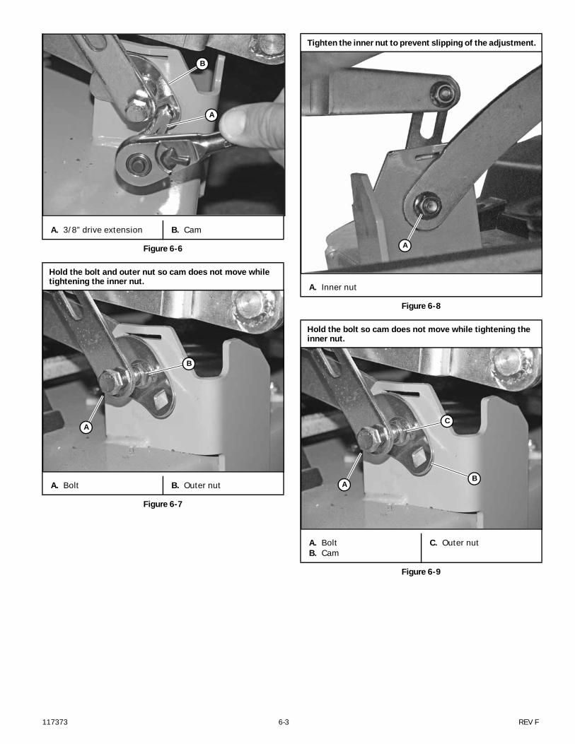
8. Pivot the cam by using a 3/8” rachet and extension.Pivot the cam until the top of the deck is the same dis-tance from the ground as the right side. Figure 6-6
9. To allow for easier access when tightening the adjust-ing hardware, lower the deck to its lowest position.
10. Tighten the cam hardware.
Mowers built prior to serial number 14030000 – Whentightening the cam hardware you must tighten the innernut while holding the bolt and outer nut to keep the camfrom rotating and changing the adjustment. The innernut must be tight to prevent cam movement. Figure 6-7& Figure 6-8
Mowers built after serial number 14030000 – Whentightening the cam hardware you must tighten the outernut against the cam while keeping the cam from rotating.Use a 3/8” rachet and extension to hold the cam toprevent it from rotating. The outer nut must be tight toprevent cam movement. Figure 6-6 & Figure 6-9
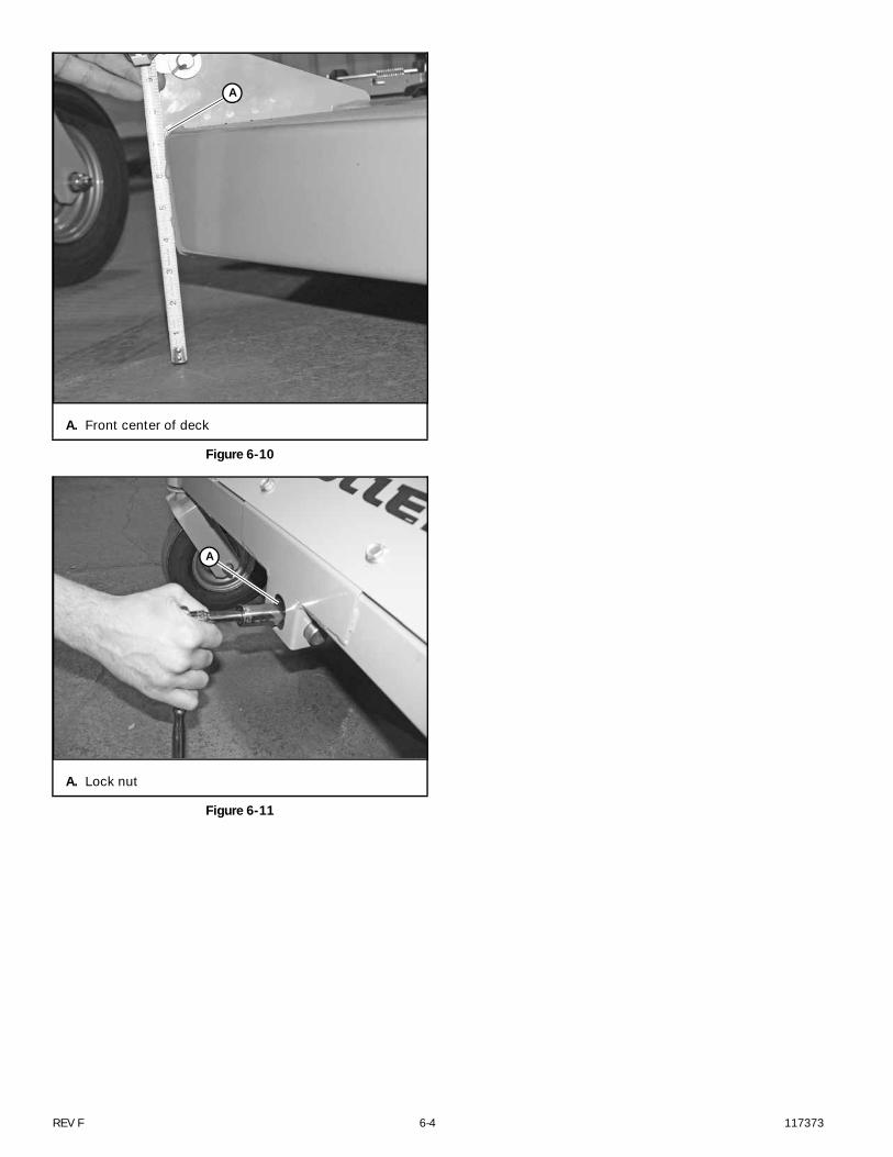
11. Go to the front of the deck and measure the center ofthe deck from the ground to the top of the deck. Thisdistance should be 1/8" to 3/8" less than the rear cor-ner dimensions. If it is not then it will be necessary toadjust the deck front to back. Figure 6-10
12. Level the front of the deck by turning the lock nut, atthe front of the mower, until the correct distance fromthe ground to the top of the deck is attained.Figure 6-11
Stop engine. Make sure deck clutch switch is in thedown (OFF) position. Remove ignition key. Placesteering control levers in the park brake position.Make sure blades are stopped before leaving seat.
A. Height adjusting lever
Figure 6-1
WAR
NIN
G
A
A. Make sure this hardware is tight
Figure 6-2
A
REV F 6-2 117373
A. Measure to top of deck
Figure 6-3
A
A. Measure to top of deck
Figure 6-4
A. Hardware B. Cam
Figure 6-5
A
A
B
117373 6-3 REV F
A. 3/8” drive extension B. Cam
Figure 6-6
Hold the bolt and outer nut so cam does not move while tightening the inner nut.
A. Bolt B. Outer nut
Figure 6-7
A
B
A
B
Tighten the inner nut to prevent slipping of the adjustment.
A. Inner nut
Figure 6-8
Hold the bolt so cam does not move while tightening the inner nut.
A. BoltB. Cam
C. Outer nut
Figure 6-9
A
A
C
B
REV F 6-4 117373
A. Front center of deck
Figure 6-10
A. Lock nut
Figure 6-11
A
A
117373 6-5 REV F
Blades
Mower blade maintenanceRefer to the Mower blade replacement section for blade
removal and installation.
Check the mower blades daily as they are the key to powerefficiency and well groomed turf. Keep the blades sharp. Adull blade will tear rather than cut the grass, leaving a brownragged top on the grass within a few hours. A dull blade alsorequires more power from the engine.
Replace any blade which is bent, cracked or broken.
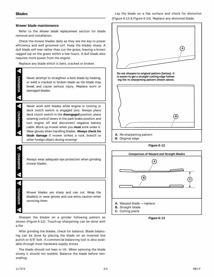
Sharpen the blades on a grinder following pattern asshown (Figure 6-12). Touch-up sharpening can be done witha file
After grinding the blades, check for balance. Blade balanc-ing can be done by placing the blade on an inverted linepunch or 5/8" bolt. A commercial balancing tool is also avail-able through most hardware supply stores.
The blade should not lean or tilt. When spinning the bladeslowly it should not wobble. Balance the blade before rein-stalling.
Lay the blade on a flat surface and check for distortion(Figure 6-13 & Figure 6-14). Replace any distorted blade.
Never attempt to straighten a bent blade by heating,or weld a cracked or broken blade as the blade maybreak and cause serious injury. Replace worn ordamaged blades.
Never work with blades while engine is running ordeck clutch switch is engaged (on). Always placedeck clutch switch in the disengaged position, placesteering control levers in the park brake position andturn engine off and disconnect negative batterycable. Block up mower when you must work under it.Wear gloves when handling blades. Always check forblade damage if mower strikes a rock, branch orother foreign object during mowing!
Always wear adequate eye protection when grindingmower blades.
Mower blades are sharp and can cut. Wrap theblade(s) or wear gloves and use extra caution whenservicing them.
WAR
NIN
GW
ARN
ING
WAR
NIN
GW
ARN
ING
A. Re-sharpening patternB. Original edge
Figure 6-12
Comparison of Warped and Straight Blades
A. Warped blade — replaceB. Straight bladeC. Cutting plane
Figure 6-13
Do not sharpen to original pattern (below). It is easier to get a straight cutting edge follow-ing the re-sharpening pattern shown above.
A
B
A
B C
REV F 6-6 117373
Mower blade replacement
1. Park the mower on a flat surface and stop the engine.Make sure deck clutch switch is in the down (OFF)position. Remove ignition key. Place the steering con-trol levers in the park brake position. Make sure theblades are stopped before leaving seat. Disconnectthe negative battery cable.
2. Raise the front of the unit and block with certified jackstands. This allows easier access to the blades underthe deck.
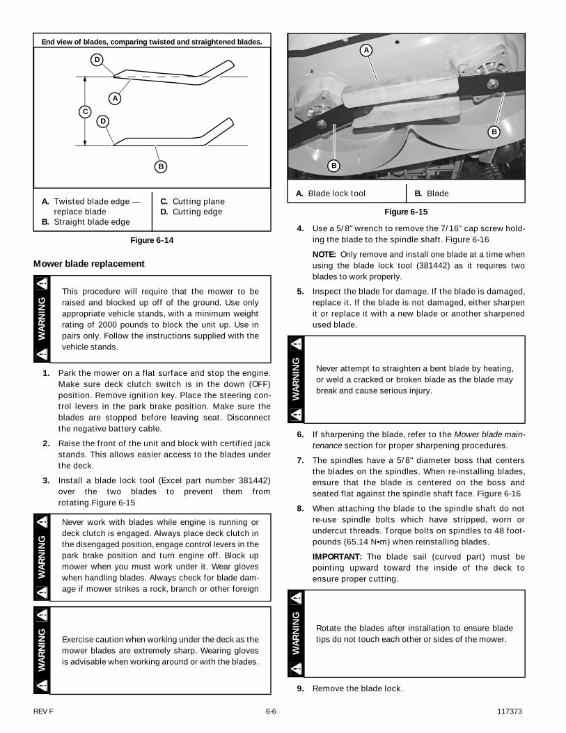
3. Install a blade lock tool (Excel part number 381442)over the two blades to prevent them fromrotating.Figure 6-15
4. Use a 5/8" wrench to remove the 7/16” cap screw hold-ing the blade to the spindle shaft. Figure 6-16
NOTE: Only remove and install one blade at a time whenusing the blade lock tool (381442) as it requires twoblades to work properly.
5. Inspect the blade for damage. If the blade is damaged,replace it. If the blade is not damaged, either sharpenit or replace it with a new blade or another sharpenedused blade.
6. If sharpening the blade, refer to the Mower blade main-tenance section for proper sharpening procedures.
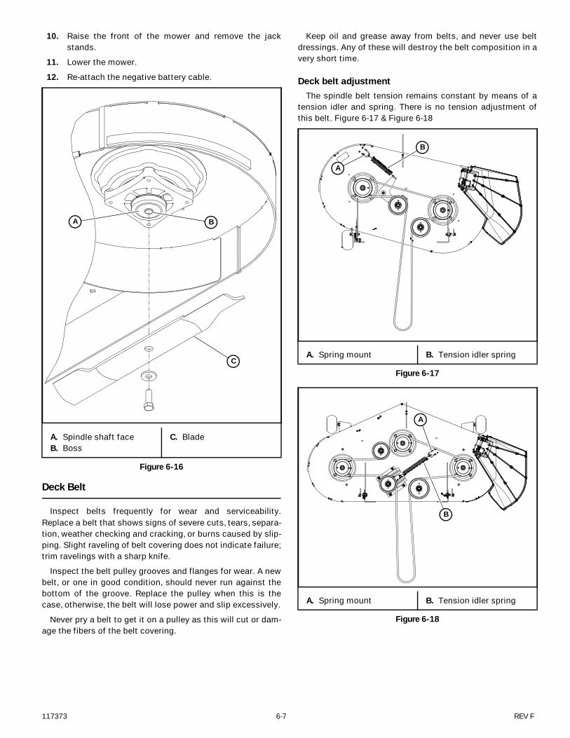
7. The spindles have a 5/8" diameter boss that centersthe blades on the spindles. When re-installing blades,ensure that the blade is centered on the boss andseated flat against the spindle shaft face. Figure 6-16
8. When attaching the blade to the spindle shaft do notre-use spindle bolts which have stripped, worn orundercut threads. Torque bolts on spindles to 48 foot-pounds (65.14 N•m) when reinstalling blades.
IMPORTANT: The blade sail (curved part) must bepointing upward toward the inside of the deck toensure proper cutting.
9. Remove the blade lock.
End view of blades, comparing twisted and straightened blades.
A. Twisted blade edge — replace blade
B. Straight blade edge
C. Cutting planeD. Cutting edge
Figure 6-14
This procedure will require that the mower to beraised and blocked up off of the ground. Use onlyappropriate vehicle stands, with a minimum weightrating of 2000 pounds to block the unit up. Use inpairs only. Follow the instructions supplied with thevehicle stands.
Never work with blades while engine is running ordeck clutch is engaged. Always place deck clutch inthe disengaged position, engage control levers in thepark brake position and turn engine off. Block upmower when you must work under it. Wear gloveswhen handling blades. Always check for blade dam-age if mower strikes a rock, branch or other foreign
Exercise caution when working under the deck as themower blades are extremely sharp. Wearing glovesis advisable when working around or with the blades.
A
C
D
D
B
WAR
NIN
GW
ARN
ING
WAR
NIN
G
A. Blade lock tool B. Blade
Figure 6-15
Never attempt to straighten a bent blade by heating,or weld a cracked or broken blade as the blade maybreak and cause serious injury.
Rotate the blades after installation to ensure bladetips do not touch each other or sides of the mower.
A
B
B
WAR
NIN
GW
ARN
ING
117373 6-7 REV F
10. Raise the front of the mower and remove the jackstands.
11. Lower the mower.
12. Re-attach the negative battery cable.
Deck Belt
Inspect belts frequently for wear and serviceability.Replace a belt that shows signs of severe cuts, tears, separa-tion, weather checking and cracking, or burns caused by slip-ping. Slight raveling of belt covering does not indicate failure;trim ravelings with a sharp knife.
Inspect the belt pulley grooves and flanges for wear. A newbelt, or one in good condition, should never run against thebottom of the groove. Replace the pulley when this is thecase, otherwise, the belt will lose power and slip excessively.
Never pry a belt to get it on a pulley as this will cut or dam-age the fibers of the belt covering.
Keep oil and grease away from belts, and never use beltdressings. Any of these will destroy the belt composition in avery short time.
Deck belt adjustmentThe spindle belt tension remains constant by means of a
tension idler and spring. There is no tension adjustment ofthis belt. Figure 6-17 & Figure 6-18
A. Spindle shaft faceB. Boss
C. Blade
Figure 6-16
BA
CA. Spring mount B. Tension idler spring
Figure 6-17
A. Spring mount B. Tension idler spring
Figure 6-18
A
B
A
B
REV F 6-8 117373
Deck belt replacement
1. Park the mower on a flat surface and stop the engine.Make sure deck clutch switch is in the down (OFF)position. Remove ignition key. Place the steering con-trol levers in the park brake position. Make sure theblades are stopped before leaving seat. Disconnectthe negative battery cable.
2. Lower the deck to the lowest setting.
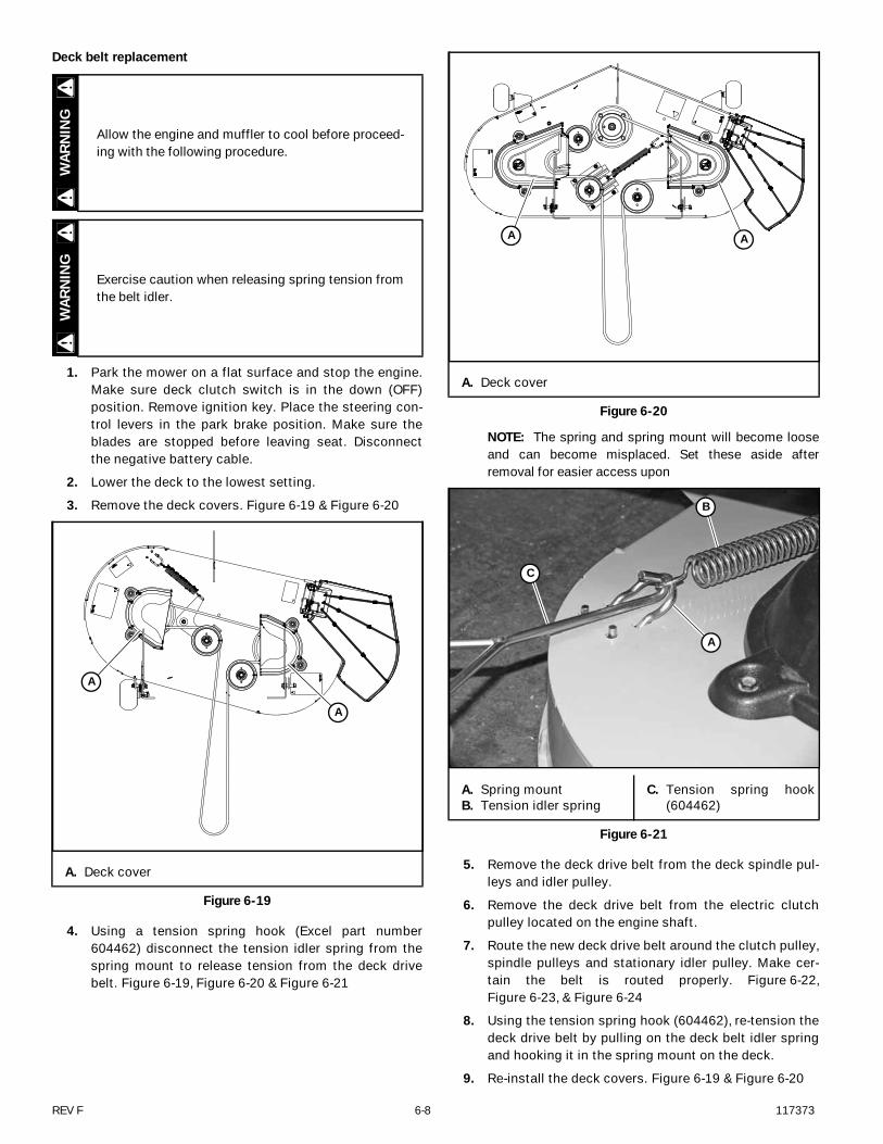
3. Remove the deck covers. Figure 6-19 & Figure 6-20
4. Using a tension spring hook (Excel part number604462) disconnect the tension idler spring from thespring mount to release tension from the deck drivebelt. Figure 6-19, Figure 6-20 & Figure 6-21
NOTE: The spring and spring mount will become looseand can become misplaced. Set these aside afterremoval for easier access upon
5. Remove the deck drive belt from the deck spindle pul-leys and idler pulley.
6. Remove the deck drive belt from the electric clutchpulley located on the engine shaft.
7. Route the new deck drive belt around the clutch pulley,spindle pulleys and stationary idler pulley. Make cer-tain the belt is routed properly. Figure 6-22,Figure 6-23, & Figure 6-24
8. Using the tension spring hook (604462), re-tension thedeck drive belt by pulling on the deck belt idler springand hooking it in the spring mount on the deck.
9. Re-install the deck covers. Figure 6-19 & Figure 6-20
Allow the engine and muffler to cool before proceed-ing with the following procedure.
Exercise caution when releasing spring tension fromthe belt idler.
A. Deck cover
Figure 6-19
WAR
NIN
GW
ARN
ING
A
A
A. Deck cover
Figure 6-20
A. Spring mountB. Tension idler spring
C. Tension spring hook(604462)
Figure 6-21
AA
C
B
A
117373 6-9 REV F
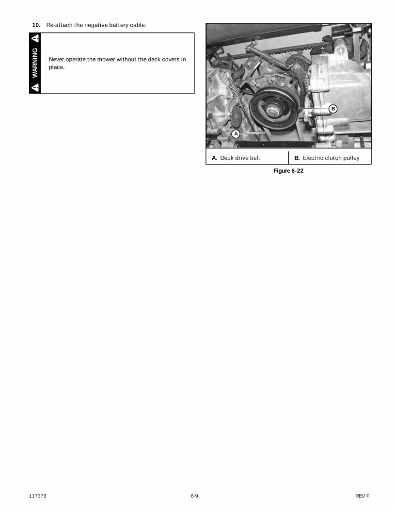
10. Re-attach the negative battery cable.
Never operate the mower without the deck covers inplace.
WAR
NIN
G
A. Deck drive belt B. Electric clutch pulley
Figure 6-22
B
A
REV F 6-10 117373
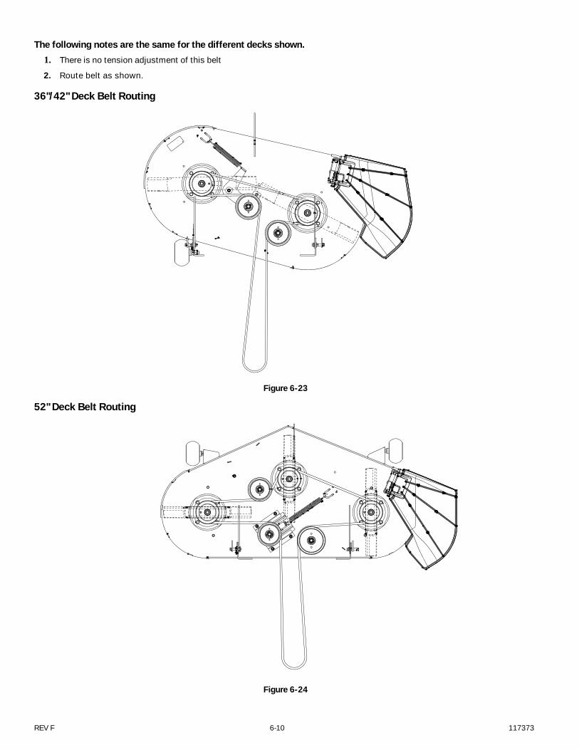
The following notes are the same for the different decks shown.1. There is no tension adjustment of this belt
2. Route belt as shown.
36"/42" Deck Belt Routing
52" Deck Belt Routing
Figure 6-23
Figure 6-24
117373 7-1 REV F
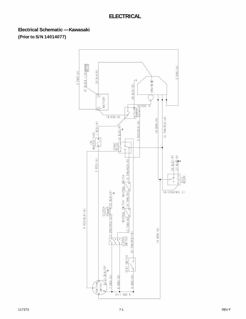
ELECTRICAL
Electrical Schematic — Kawasaki(Prior to S/N 14014077)
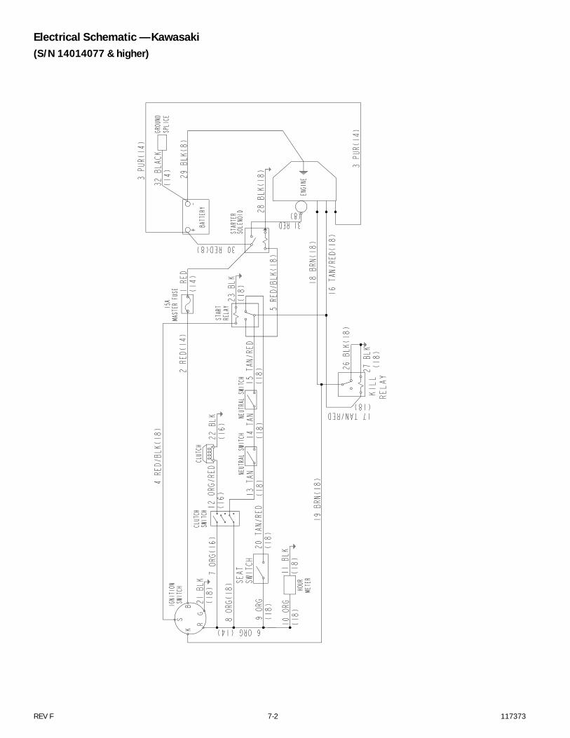
REV F 7-2 117373
Electrical Schematic — Kawasaki(S/N 14014077 & higher)
117373 7-3 REV F
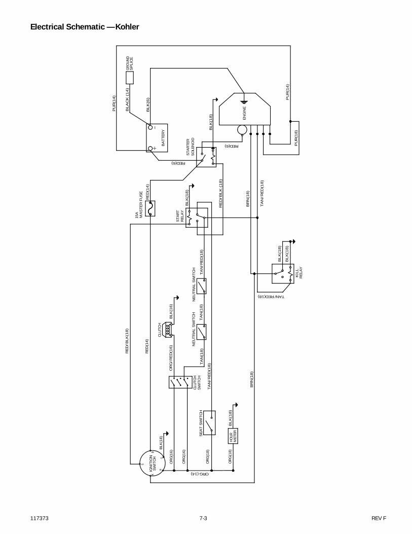
Electrical Schematic — Kohler
SWIT
CHIG
NIT
ION
B
GR
K
S
STA
RT
KIL
LR
ELA
Y
CLU
TCH
SWIT
CH
CLU
TCH
ENG
INE
BA
TTER
Y
NEU
TRA
L S
WIT
CH
NEU
TRA
L S
WIT
CH
SEA
T S
WIT
CH
STA
RTE
RSO
LEN
OID
RED
(14)
BR
N(1
8)
OR
G/R
ED
(16)
TA
N(1
8)
TA
N/R
ED
(18
)
TA
N/R
ED
(18)
TAN/RED(18)
TA
N/R
ED
(18
)
BL
K(6
)
RED(6)
RED(6)
PU
R(1
4)
BLK
(18
)
BLK
(18
)
BLK
(18
)
MA
STE
R F
US
E15
A
PU
R(1
4)
TA
N(1
8)
REL
AY
RE
D(1
4)
BLK
(16)
BL
AC
K (
14
)
ORG (14)
HOUR
MET
ER B
LK(1
8)
PU
R(1
8)
-+
BR
N(1
8)
RE
D/B
LK
(1
8)
BL
K(1
8)
GROU
ND
SP
LIC
E
OR
G(1
8)
OR
G(1
8)
OR
G(1
6)
OR
G(1
6)
BLK(
18)
RE
D/B
LK(1
8)

REV F 7-4 117373

117373 8-1 REV F
MAINTENANCE
NOTES:1. Initial oil change is after 5 hours of operation. Thereafter, change oil after every 40 hours operation. Change more often under dusty or dirty con-
ditions and during hot weather periods.2. Torque initially and after first 2 hours of operation.3. Change engine oil filter per the engine manufacturer’s recommendations. Refer to Engine Owner’s Manual for recommendations and other
maintenance items..4. Service more often under dusty or dirty conditions.5. Pump drive belt only - Inspect every month and replace if worn or cracking is noticed. Otherwise, replace every 2 years.6. Check fuel system for any crack or leaks including, but not limit to, fuel line hoses, fuel valve, vent line hoses, vent valve, vapor valve, carbon can-
ister, and grommets. Replace as needed.7. More often under dusty or dirty conditions and during hot weather.
REFERENCES:A. Refer to engine owner’s manual for engine service information.NOTE: After completing maintenance cycle (100 hours), repeat cycle.
Maintenance ScheduleRefer to Figure 8-1, Figure 8-2, Figure 8-3, Figure 8-4,
Figure 8-5, Figure 8-6, & Figure 8-7
SERVICE ATINTERVALS INDICATED
WEEKLYOR 40
HOURS
ANNUALLYOR 100HOURS
Verify safety start interlock system Prior to each use
Visually inspect unit for loose hardware and/or damaged parts Prior to each use
Visually inspect tires Prior to each use
Check oil level, engine (1) Prior to each use or every 4 hours
Clean air intake screen (4) Prior to each use or every 4 hours
Check fuel level Prior to each use
Blades - sharpen & securely fastened Prior to each use
Discharge chute - securely in place & in lowest position Prior to each use
Check tire pressure with a gauge Prior to each use
Clean engine and transaxle compartment After each use
Grease gauge wheel bearings X
Change engine oil & filter (1)(3) X
Check battery connections X
Clean engine exterior (a) X
Replace air cleaner paper element (4) X
Check pump & deck belt tension and condition (5) X
Check fuel system (6) X
Check fuel tank grommet (6) X
Tighten lug nuts on wheels (2) X
Change fuel filter (6) X
Replace fuel evaporation system filter (7) X
REV F 8-2 117373
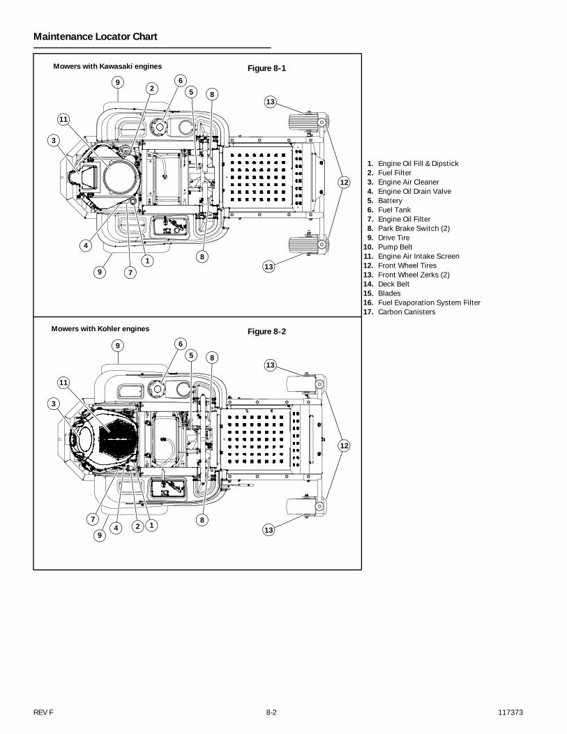
Maintenance Locator Chart
1. Engine Oil Fill & Dipstick2. Fuel Filter3. Engine Air Cleaner4. Engine Oil Drain Valve5. Battery6. Fuel Tank7. Engine Oil Filter8. Park Brake Switch (2)9. Drive Tire
10. Pump Belt11. Engine Air Intake Screen12. Front Wheel Tires13. Front Wheel Zerks (2)14. Deck Belt15. Blades16. Fuel Evaporation System Filter17. Carbon Canisters
Figure 8-1Mowers with Kawasaki engines
2
3
4
56
79
9
13
1
8
8
11
12
13
Figure 8-2Mowers with Kohler engines
47
9
12
12
138
9
3
11
1385
6
117373 8-3 REV F
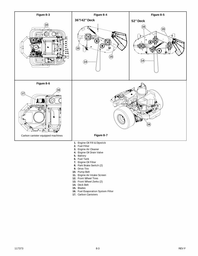
Figure 8-3 Figure 8-4 Figure 8-5
Figure 8-6
Figure 8-7
1. Engine Oil Fill & Dipstick2. Fuel Filter3. Engine Air Cleaner4. Engine Oil Drain Valve5. Battery6. Fuel Tank7. Engine Oil Filter8. Park Brake Switch (2)9. Drive Tire
10. Pump Belt11. Engine Air Intake Screen12. Front Wheel Tires13. Front Wheel Zerks (2)14. Deck Belt15. Blades16. Fuel Evaporation System Filter17. Carbon Canisters
10
36”/42” Deck
15
15
14
52” Deck
1515
14
Carbon canister equipped machines
1716
16

REV F 8-4 117373
117373 9-1 REV F
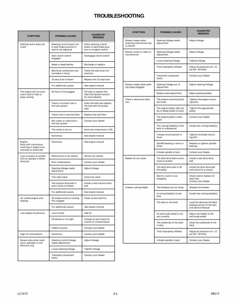
TROUBLESHOOTING
SYMPTOMS PROBABLE CAUSES SUGGESTEDREMEDIES
Starting motor does not crank
Steering control levers not in park brake position or switch not adjusted
Place steering control levers in park brake posi-tion or re-adjust switch
Deck clutch switch engaged
Disengage clutch switch
Weak or dead battery Recharge or replace
Electrical connections are corroded or loose
Check the electrical con-nections
15 amp fuse is blown Replace the 15 amp fuse
For additional causes See engine manual
The engine will not start, starts hard or fails to keep running
No fuel or line plugged Fill tank or replace line (See Fuel System section for more details)
There is incorrect fuel in the fuel system
Drain the tank and replace the fuel with the proper type
There is dirt in the fuel filter Replace the fuel filter
Dirt, water or stale fuel in the fuel system
Contact your Dealer
The choke is not on Move the choke lever to ON
Numerous See engine manual
Engine:Runs with continuous misfiring or engine runs unevenly or erratically
Numerous See engine manual
Loss of power or system will not operate in either direction
Restrictions in air cleaner Service air cleaner
Poor compression Contact your Dealer
Steering linkage needs adjustment
Adjust linkage
Tow valve open Close tow valve
The traction drive belt is worn, loose or broken
Install a new traction drive belt
For additional causes See engine manual
Air cooled engine over-heating
Air intake screen or cooling fins clogged
Clean screen and fins
For additional causes See engine manual
Low engine oil pressure Low oil level Add oil
Oil diluted or too light Change oil and check for source of contamination
Failed oil pump Contact your Dealer
High oil consumption Numerous Contact your Dealer
Mower jerky when start-ing or operates in one direction only
Steering control linkage needs adjustment
Adjust linkage
Loose steering linkage Tighten linkage
Transaxle component faulty
Contact your Dealer
Mower creeps when steering control levers are in neutral
Steering linkage needs adjustment
Adjust linkage
Mower circles or veers in one direction
Steering linkage needs adjustment
Adjust linkage
Loose steering linkage Tighten linkage
Tires improperly inflated Adjust air pressure to 8 - 12 psi (55 - 83 KPa)
Transaxle component faulty
Contact your Dealer
Mower creeps when park-ing brake engaged
Steering linkage out of adjustment
Adjust steering linkage
Brakes need adjustment Adjust parking brakes
There is abnormal vibra-tion
The engine mounting bolts are loose
Tighten the engine mount-ing bolts
The engine pulley, idler pul-ley or blade pulley is loose
Tighten the appropriate pulley
The engine pulley is dam-aged
Contact your Dealer
The cutting blade(s) is/are bent or unbalanced
Install new cutting blade(s)
A blade mounting bolt is loose
Tighten the blade mount-ing bolt
Spindle bearing is worn or loose
Replace or tighten spindle bearing
A blade spindle is bent Contact your Dealer
Blades do not rotate The deck drive belt is worn, loose or broken
Install a new deck drive belt
The deck drive belt is off the pulley
Install the deck drive belt and check for a reason
Electric clutch is not engaging
Check and/or replace 15 amp fuse.Contact your Dealer
Uneven cutting height The blade(s) are not sharp Sharpen the blades
A cutting blade(s) is/are bent
Install new cutting blade(s)
The deck is not level Level the deck per the Deck leveling section of the Gen-eral Service Manual
An anti-scalp wheel is not set correctly
Adjust the height of the anti-scalp wheel
The underside of the deck is dirty
Clean the underside of the deck
Tires improperly inflated Adjust air pressure to 8 - 12 psi (55 - 83 KPa)
A blade spindle is bent Contact your Dealer
SYMPTOMS PROBABLE CAUSES SUGGESTEDREMEDIES

REV F 9-2 117373

117373 i-1 REV F
INDEXPAGE PAGE
Belt adjustment .........................................................4-4
Belt replacement ........................................................4-4
Blades .......................................................................6-5
Carbon Canister .........................................................5-2
Control lever stops adjustment ..................................4-2
Deck belt ...................................................................6-7
Deck belt adjustment .................................................6-7
Deck belt replacement ...............................................6-8
Deck belt routing .....................................................6-10
Deck leveling .............................................................6-1
Electrical Schematic .................................... 7-1, 7-2, 7-3
Engine air filter ..........................................................5-1
Engine oil and filter ....................................................5-1
Engine RPM settings ..................................................5-5
Fuel and Evaporative System Line Routing .................5-2
Fuel evaporation system filter ....................................5-2
General engine maintenance ......................................5-1
General maintenance precautions ..............................2-2
Hustler service program ............................................ 1-1
Maintenance introduction ......................................... 1-1
Maintenance locator chart ........................................ 8-2
Maintenance precautions .......................................... 2-3
Mower blade maintenance ........................................ 6-5
Mower blade replacement ......................................... 6-6
Operate machine safely ............................................. 2-2
Operation Precautions .............................................. 2-2
Park brake spring adjustment .................................... 4-3
Pre-operation precautions ......................................... 2-1
Safe servicing practices ............................................ 2-1
Special torques ......................................................... 3-1
Standard torques ...................................................... 3-1
Steering adjustments ................................................ 4-1
Steering control lever neutral adjustment .................. 4-1
Tires ......................................................................... 4-6
Transaxle Drive Belt .................................................. 4-4
Warranty ................................................................... 1-1