HTR Process Heat Applications - Atoms for Peace and ...€¦ · HTR Process Heat Applications ......
20
HTR Process Heat Applications Japan Atomic Energy Agency Training Course on High Temperature Gas-cooled Reactor Technology October 19-23, Serpong, Indonesia
Transcript of HTR Process Heat Applications - Atoms for Peace and ...€¦ · HTR Process Heat Applications ......

HTR Process Heat Applications
Japan Atomic Energy Agency
Training Course on
High Temperature Gas-cooled Reactor Technology
October 19-23, Serpong, Indonesia

p.2
HTR Heat Applications
HTGR
Intermediate
heat exchanger Steam
generator
Efficient heat utilization
Waste heat utilization
Process steam supply
High-temperature steam
supply system
Electricity supply
Electric generation system
(Using gas & steam turbine)
950℃~
750℃
Hydrogen supply
950℃
・District heating
・Desalination
・Hot water aquaculture
・Heating cultivation
Hydrogen production
・Fuel-cell vehicle
・Hydrogen reduction
ironmaking
・Chemical production
・People’s livelihood
・Private electric generation
・Chemical industry
・Petroleum refining
750℃~
550℃
500℃~
600℃
Cooler
200℃
150℃
Fuel:
U, Pu, Th, MOX
900℃~
850℃
H2 potentially substitutes for fossil fuels in heat utilization field
H2 production process converts nuclear energy into H2
Heat source for various heat applications
p.3
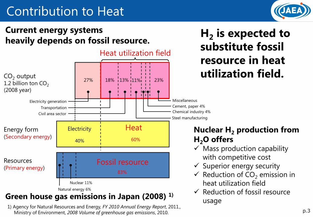
Contribution to Heat
27% 18% 13% 11% 23%
Electricity
40%
Heat
60%
Fossil resource
CO2 output 1.2 billion ton CO2
(2008 year)
Energy form (Secondary energy)
Resources (Primary energy)
1) Agency for Natural Resources and Energy, FY 2010 Annual Energy Report, 2011.,
Ministry of Environment, 2008 Volume of greenhouse gas emissions, 2010.
83%
Chemical industry 4%
Cement, paper 4%
Electricity generation
Transportation
Civil area sector Steel manufacturing
Miscellaneous
Heat utilization field
Nuclear 11%
Natural energy 6%
Green house gas emissions in Japan (2008) 1)
Current energy systems
heavily depends on fossil resource. H2 is expected to
substitute fossil
resource in heat
utilization field.
Nuclear H2 production from
H2O offers Mass production capability
with competitive cost
Superior energy security
Reduction of CO2 emission in
heat utilization field
Reduction of fossil resource
usage

p.4
Why Hydrogen ?
Energy +
2H2(g) + O2(g) = 2H2O(l) + 572 kJ
Hydrogen acts as energy carrier
Advantages
Can be produced from H2O
—no limitations of feedstock
Changes into water by combustion
—no environmental pollution
Small loss in transport
—pipe lines, tankers
Various storage technologies
—high pressure gas, liquefied hydrogen,
metal/organic hydride
Wide range of usage
—fuel, reducer for chemical industry and
ironmaking, power conversion for electricity

H2 Production with Nuclear Energy
p.5
Heat
Fossil fuels
Water
Hydrocarbon Water Water
Electricity
Heat
Water
Heat
Water
Electricity
Heat
Steam reforming Electrolysis
High-
temperature
Steam electrolysis
Thermochemical
water-splitting
Hybrid
thermochemical
water-splitting
(Hybrid-TC)
Energy
forms
Feed-
stocks
Methods
Light-water reactor
(LWR)
< 325oC
Electricity
Fast breeder reactor
(FBR)
< 550oC
Electricity
Heat
High temperature gas-cooled reactor
(HTGR)
750-950oC
Electricity
Heat
Primary
energy
Nuclear energy
Hydrogen
Electricity

Methane Steam Reforming using Fossil Fuel
p.6
Steam reforming reaction (endothermic)
CH4 + H2O → CO + 3H2, ΔH=206 kJ/mol
Water gas shift reaction (exothermic)
CO + H2O → CO2 + H2, ΔH=−41 kJ/mol
Commercialized method and
widely use in the world
Produce greater part of
worldwide H2 production
Use combustion heat
of methane Energy
Methane
HTGR coupled steam methane
reforming plant can Early deployable because the
technology in H2 production
section is matured
Can save methane and reduce Co2
emission by supplying
heat by nuclear reactor
Steam reforming plant
p.7
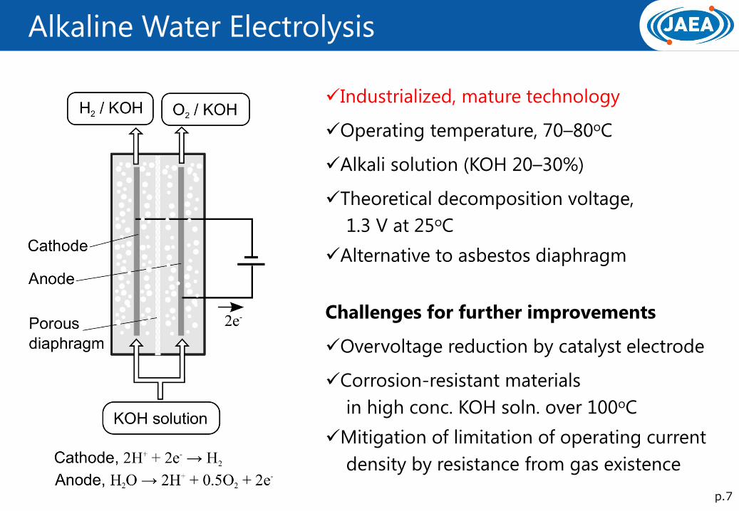
Alkaline Water Electrolysis
Industrialized, mature technology
Operating temperature, 70–80oC
Alkali solution (KOH 20–30%)
Theoretical decomposition voltage,
1.3 V at 25oC
Alternative to asbestos diaphragm
Challenges for further improvements
Overvoltage reduction by catalyst electrode
Corrosion-resistant materials
in high conc. KOH soln. over 100oC
Mitigation of limitation of operating current
density by resistance from gas existence

p.8
High Temperature Steam Electrolysis
Higher temperature, lower
voltage (=smaller electric energy)
Theoretical decomposition voltage,
ca. 0.9 V at 1000oC
Solid oxide electrolyte
(oxygen ion conductive; e.g. yttria stabilized
zirconia (YSZ))
Cells are built mostly of ceramics material
Plate type cell or cylindrical type cell
External heating (higher eff.) or autothermal
Challenges
Upsizing ceramics parts
Reduction of performance degradation
Durability against thermal cycle

p.9
Thermochemical Cycle
Chemical process for water splitting
Suitable for on-site production
in large volume
Advantages
Smaller electricity demand
than electrolysis
Realistic operating temperature well
suited for industrial plant
Possibility of higher thermal efficiency
Possibility of higher scale merit
in economic terms
Thermochemical water-splitting cycle has
the same function as heat engine

p.10
Desirable thermochemical cycle
Small number of chemical reactions
Small number of elements
Temperature range consistent with heat source temperature
Liquid/gas phase operation
High thermal efficiency and low cost
Desirable features

p.11
Copper-chlorine cycle
Number of reactions: 3
Number of element: 4
Maximum temperature: 500oC
(matching Super-Critical Water
Reactor)
Including solid handling
One electrochemical reaction
Practicability for elemental reactions
were demonstrated separately
on lab-scale
p.12
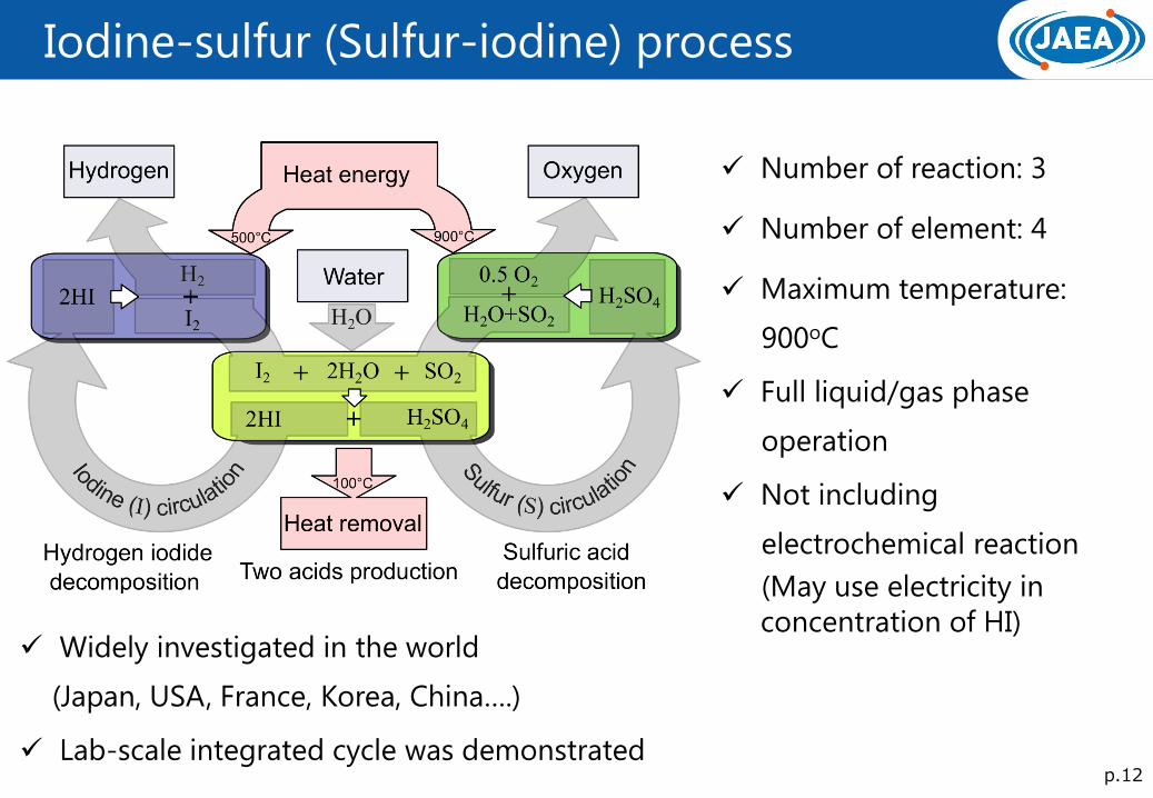
Iodine-sulfur (Sulfur-iodine) process
Number of reaction: 3
Number of element: 4
Maximum temperature:
900oC
Full liquid/gas phase
operation
Not including
electrochemical reaction
(May use electricity in
concentration of HI) Widely investigated in the world
(Japan, USA, France, Korea, China….)
Lab-scale integrated cycle was demonstrated
p.13
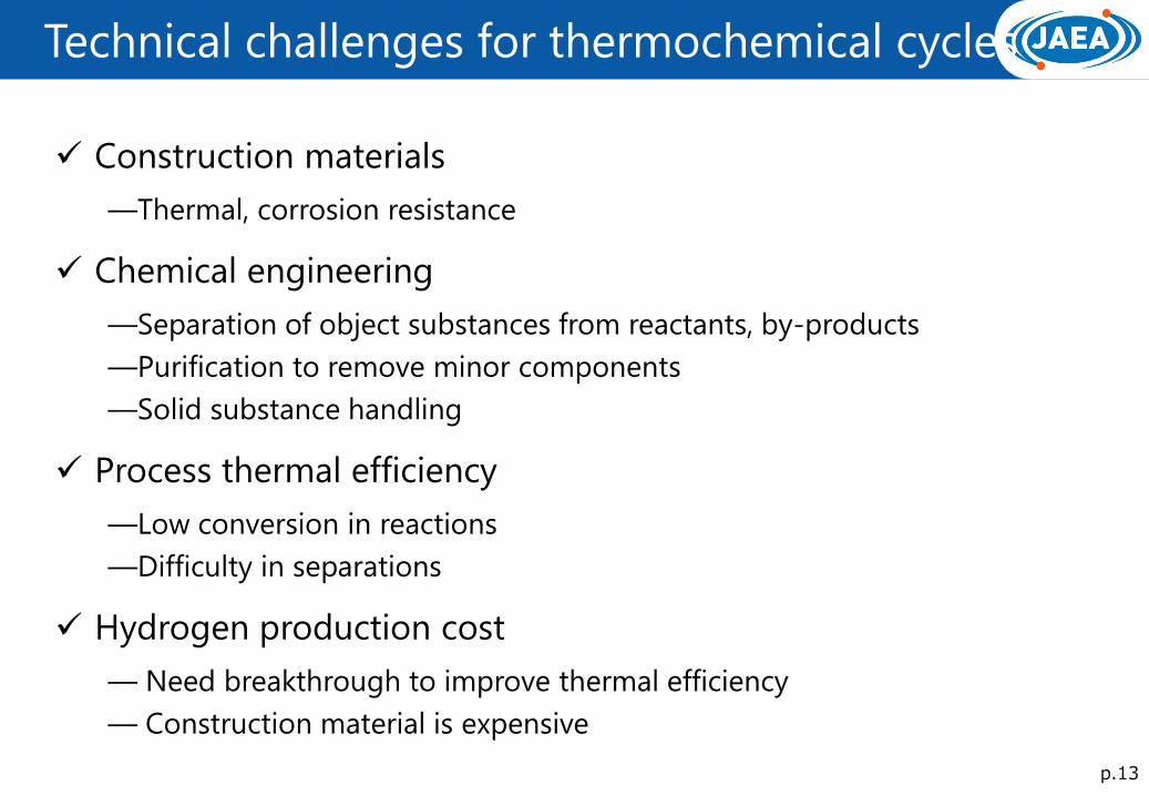
Technical challenges for thermochemical cycles
Construction materials
—Thermal, corrosion resistance
Chemical engineering
—Separation of object substances from reactants, by-products
—Purification to remove minor components
—Solid substance handling
Process thermal efficiency
—Low conversion in reactions
—Difficulty in separations
Hydrogen production cost
— Need breakthrough to improve thermal efficiency
— Construction material is expensive

p.14
High Efficient Power Generation
1) X. Yan et al., Nucl. Eng. Des., 222 (2003) 247-262.
Heat (He)
Reactor Gas turbine
Elec.
Electricity generation Key process parameters1) (design example)
High generating efficiency (46.8%)
is expected
Simplicity of equipments
configuration (no water handling,
no secondary system)
Closed regenerative Brayton cycle High-T and high-P Helium gas circulates through a
loop composed of
gas turbine, recuperator, precooler, compressor
and reactor.
p.15
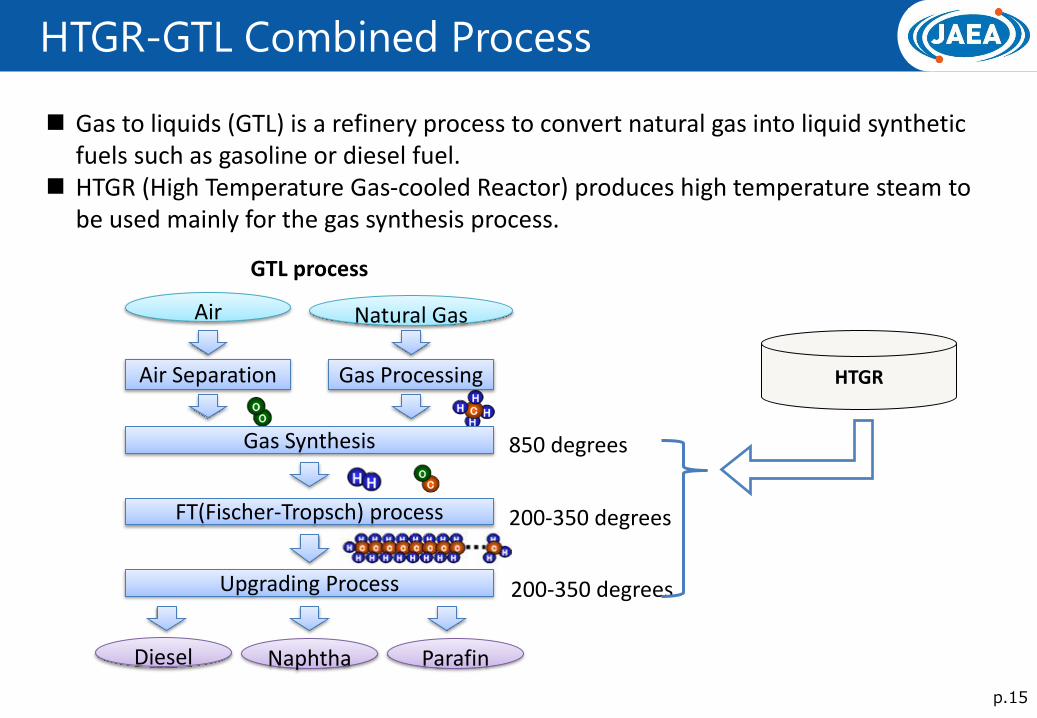
HTGR-GTL Combined Process
Gas to liquids (GTL) is a refinery process to convert natural gas into liquid synthetic fuels such as gasoline or diesel fuel.
HTGR (High Temperature Gas-cooled Reactor) produces high temperature steam to be used mainly for the gas synthesis process.
Gas Synthesis
FT(Fischer-Tropsch) process
Upgrading Process
Diesel Naphtha Parafin
Air Separation
Air
Gas Processing
Natural Gas
850 degrees
200-350 degrees
200-350 degrees
GTL process
HTGR
p.16
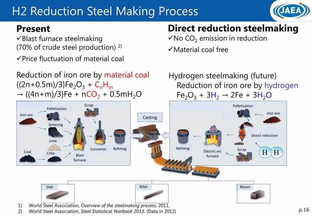
H2 Reduction Steel Making Process
1) World Steel Association, Overview of the steelmaking process, 2011.
2) World Steel Association, Steel Statistical Yearbook 2013. (Data in 2012)
Present Blast furnace steelmaking
(70% of crude steel production) 2)
Price fluctuation of material coal
Direct reduction steelmaking No CO2 emission in reduction
Material coal free
Iron ore
Sintering
Scrap
Coal Coke
Lime
Blast furnace
Converter Refining
Casting
Refining Electric arc
furnace
Pelletization
Scrap
Iron ore
Coal
Direct reduction
Slab Billet Bloom
Natural gas etc.
Reduction of iron ore by material coal
{(2n+0.5m)/3}Fe2O3 + CnHm
→ {(4n+m)/3}Fe + nCO2 + 0.5mH2O
Hydrogen steelmaking (future)
Reduction of iron ore by hydrogen
Fe2O3 + 3H2 → 2Fe + 3H2O
Pelletization

p.17
Concept of HTGR Steelmaking Plant
Hydrogen
Electricity
High quality
steel
Direct
reduced
iron
Electricity
Heat
Heat
Heat, electricity
Material
HTGR
IS process
Helium gas
turbine
Shaft
furnace
Electric arc
furnace
IS process produces H2
HTGR can provide all necessities (heat, electricity, and H2)
Iron ore
Water

p.18
Desalination with HTGR
Precooler
Gas turbine
Reactor
Waste heat
Cooling water
Large amount of waste heat
(248 MWt for 600 MWt reactor power)
MSF is provided with power generating
installations in the Middle East
Fresh water by evaporation
incorporating latent heat recovery
Considerable economy
by upsizing of MSF plants
p.19
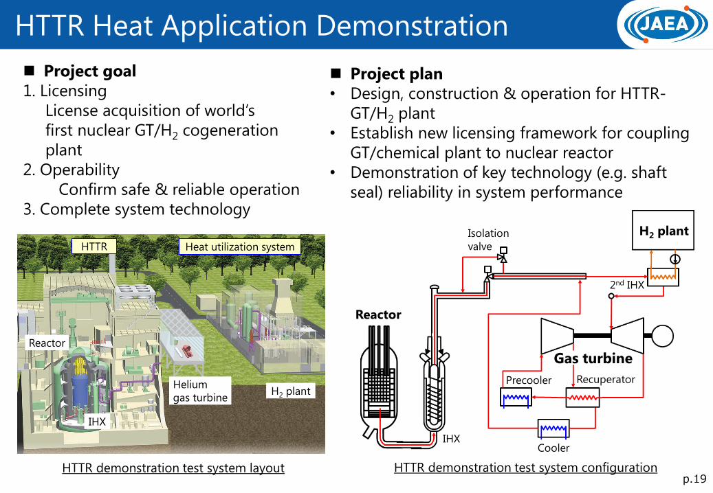
HTTR Heat Application Demonstration
Project goal
1. Licensing
License acquisition of world’s
first nuclear GT/H2 cogeneration
plant
2. Operability
Confirm safe & reliable operation
3. Complete system technology
HTTR demonstration test system layout
Reactor
IHX
Helium
gas turbine H2 plant
HTTR Heat utilization system
HTTR demonstration test system configuration
Project plan
• Design, construction & operation for HTTR-
GT/H2 plant
• Establish new licensing framework for coupling
GT/chemical plant to nuclear reactor
• Demonstration of key technology (e.g. shaft
seal) reliability in system performance
IHX
Gas turbine
Recuperator Precooler
Reactor
H2 plant
Cooler
Isolation
valve
2nd IHX
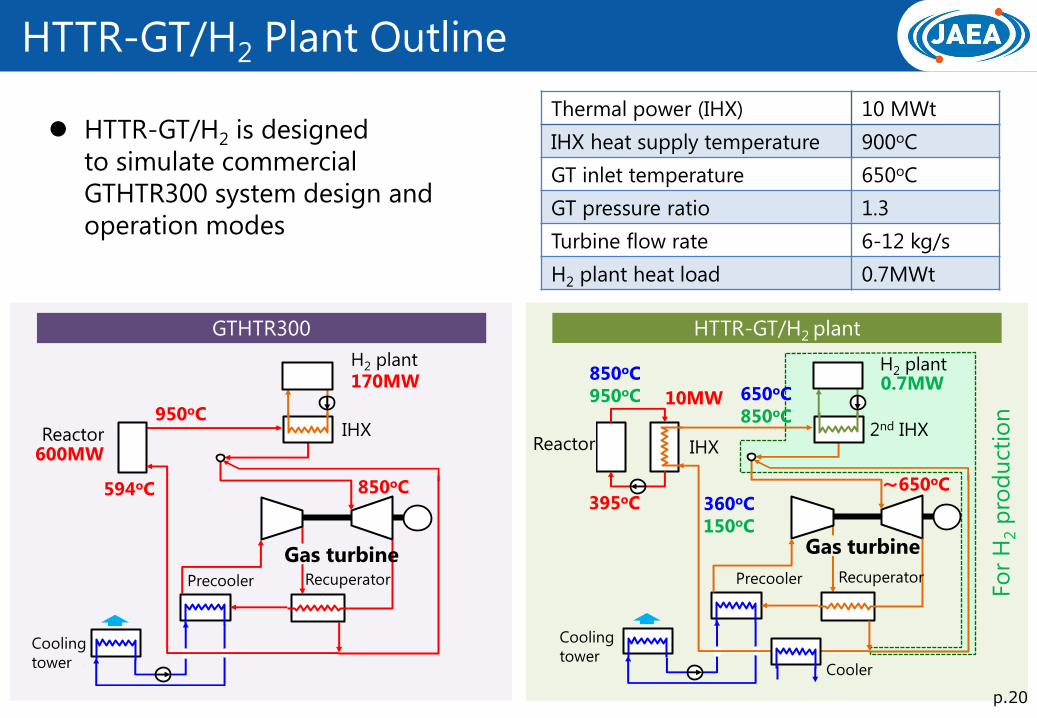
HTTR-GT/H2 Plant Outline
GTHTR300 HTTR-GT/H2 plant
H2 plant
Cooling
tower Cooler
10MW
850oC
950oC
395oC
950oC
594oC
Reactor 600MW
360oC
150oC
850oC 〜650oC
170MW 0.7MW 650oC
850oC
HTTR-GT/H2 is designed
to simulate commercial
GTHTR300 system design and
operation modes
H2 plant
Fo
r H
2 p
rod
uct
ion
2nd IHX
Gas turbine
Recuperator Precooler Recuperator Precooler
Gas turbine
Reactor
Cooling
tower
IHX IHX
Thermal power (IHX) 10 MWt
IHX heat supply temperature 900oC
GT inlet temperature 650oC
GT pressure ratio 1.3
Turbine flow rate 6-12 kg/s
H2 plant heat load 0.7MWt
p.20


![Yamaha Rx-V520 Rx-V520rds Htr-5450 Htr-5450rds [ET]](https://static.fdocuments.us/doc/165x107/5695cfce1a28ab9b028f9ca2/yamaha-rx-v520-rx-v520rds-htr-5450-htr-5450rds-et.jpg)