
HTDM 91+ OMEGA SERIESS - ICE Western Sales · QUALITY ICE is committed to providing quality through...
40
DESIGN FEATURES Reliability at its finest. HTDM 91+ OMEGA SERIES HEATING ONLY HEAT/COOL Drum & Tube Heat Exchanger. 409 Stainless Steel 14 Gauge Heat Ex- changer Material. Proprietary Tube Placement/Arrangement. Omega Air Pattern. Up To 60:1 Turndown High Efficient & Durable Digital Scroll D.X. Cooling eliminates the need for Hot Gas Bypass. 10:1 Turndown on Single Stage Com- pressors and 20:1 Turndown for Tan- dem Compressors. VFD Controlled Condenser Fan (No Fan Cycling). 9754 54 ST SE Calgary, AB—T2C 5J6 Phone: 403-252-5577 Fax: 403-252-5556 www.icewestern.com C US
-
Upload
nguyenlien -
Category
Documents
-
view
215 -
download
0
Transcript of HTDM 91+ OMEGA SERIESS - ICE Western Sales · QUALITY ICE is committed to providing quality through...

DESIGN FEATURES
Reliability at its finest.
HTDM 91+ OMEGA SERIESS
HEATING ONLY HEAT/COOL
Drum & Tube Heat Exchanger.
409 Stainless Steel 14 Gauge Heat Ex-
changer Material.
Proprietary Tube Placement/Arrangement.
Omega Air Pattern.
Up To 60:1 Turndown
High Efficient & Durable Digital
Scroll D.X. Cooling eliminates the
need for Hot Gas Bypass.
10:1 Turndown on Single Stage Com-
pressors and 20:1 Turndown for Tan-
dem Compressors.
VFD Controlled Condenser Fan (No
Fan Cycling).
9754 54 ST SE
Calgary, AB—T2C 5J6
Phone: 403-252-5577
Fax: 403-252-5556
www.icewestern.com
C US

QUALITY ICE is committed to providing quality through every step of the operation. Every product undergoes testing and quality inspection to ensure the highest standards are met. ICE employees take great pride as manufacturers of HVAC units.
SERVICE ICE provides qualified staff that can assist in start-up service and troubleshooting.
PRICE ICE offers some of the best pricing in the HVAC industry. ICE can match or surpass any competitor’s unit capabilities and quality commitments as well as meet or beat their delivery times.
CUSTOM UNITS ICE provides custom built units to meet customer specifications and exceed customer expectations. No job is too big or too difficult.
9765 54 ST SE Calgary, AB T2C 5J6
Phone: 403-252-5577 Fax: 403-252-5556
www.icewestern.com Email: Sales and Engineering: Jim Clancy, [email protected]
All models are approved according to the Standard for Gas Unit Heaters, Gas Packaged Heaters, Gas Utility Heaters, and Gas fired duct furnaces ANSI Z83.8/CSA 2.6 Issued 2013/04/01
All models are approved according to the Standard for Gas-Fired Appliances for Use at High Altitudes CGA 2.17 Issue: 1991/01/01
ICE WESTERN BELIEVES YOU DESERVE QUALITY AND SERVICE

THE REVOLUTIONARY ICECON III For the past 20 years the ICECO N III board capability has allowed ICE to create near perfect combustion
throughout the operating range of the heat exchanger. Because of this advanced technology ICE has become
very successful in producing efficient and high quality heat exchangers and burners.
The ICECON III board comes with 6 factory presets within the combustion curve. From these 6 presets a microprocessor produces an infinite number of points to precisely create the combustion curve. The ICECON III can be precisely programmed for different elevations to ensure the highest quality rate of combustio n. To acquire this near perfect combustion, the ICECON board sends signals to a Triac solid state relay which controls the rpm of the combustion motor and optimizes the gas ball valve position to allow for combustion at any set point desired. T he combustion fan information and gas valve position feedback is sent back to the ICECON III via a tac sensor for constant interlock of both variables. This technology produces quiet combustion and smooth modulation changes between low fire and high fire to ensure greater efficiency, greater control and impressive turndown ratios that cannot be matched by competitors.
ICECON III
• Heat Modes: Factory set discharge temperature
• Remote Temperature Selector (RTS)
• External modulation control
• Signal: 4-10mA, 0-10 VDC, compatible withBuilding Management Systems (BMS)
• Error signal indication:o High limito Low limito Air Provingo Flame Failureo Gas Valve
• Options:o Space Over-rideo Low Limito System Pre-heato Standby o Fan Standby
2

For more information, please call 403-252-5577 ext. 222 or visit our website: www.icewestern.com
CONTENTS
THE ICECON III BOARD .................................................................................................................................. 1
CONTENTS ..................................................................................................................................................... 2
DESIGN FEATURES ......................................................................................................................................... 4
STANDARD FEATURES ................................................................................................................................... 5
OPTIONAL FEATURES .................................................................................................................................... 5
ADDITIONAL OPTIONS .................................................................................................................................. 5
COMPANY PROFILE ....................................................................................................................................... 6
PERFORMANCE SPECIFICATIONS .................................................................................................................. 7
AMPERAGE SPECIFICATIONS ......................................................................................................................... 7
WEIGHTS (IN POUNDS) ................................................................................................................................. 8
HORIZONTAL UNITS .................................................................................................................................. 8
COMPONENTS ........................................................................................................................................... 8
EFFICIENCIES AND TURNDOWNS .................................................................................................................. 9
STATIC PRESSURE DROP(S) DUE TO ACCESSORIES ....................................................................................... 9
STANDARD FILTER SECTION SUMMARY ....................................................................................................... 9
HTDM 91 PLUS PERFORMANCE SPECIFICATIONS ....................................................................................... 10
COOLING PERFORMANCE DATA ................................................................................................................. 12
HTDM 91 PLUS SERIES ................................................................................................................................. 13
STANDARD UNIT c/w FLAT FILTER .......................................................................................................... 13
c/w FLAT FILTER & MIX BOX ................................................................................................................... 14
c/w FLAT FILTER, MIX BOX, HIGH EFFICIENCY FILTER PLENUM & HORIZONTAL DISCHARGE ................ 15
c/w FLAT FILTER, MIX BOX, HIGH EFFICIENCY FILTER PLENUM & BOTTOM DISCHARGE ....................... 16
c/w FLAT FILTER, COIL & MIX BOX .......................................................................................................... 17
c/w FLAT FILTER, COIL PLENUM & HORIZONTAL DISCHARGE ................................................................ 18
c/w FLAT FILTER, COIL PLENUM & BOTTOM DISCHARGE ....................................................................... 19
c/w FLAT FILTER, MIX BOX, COIL PLENUM & HORIZONTAL DISCHARGE ................................................ 20
c/w FLAT FILTER, MIX BOX, COIL PLENUM & BOTTOM DISCHARGE ....................................................... 21
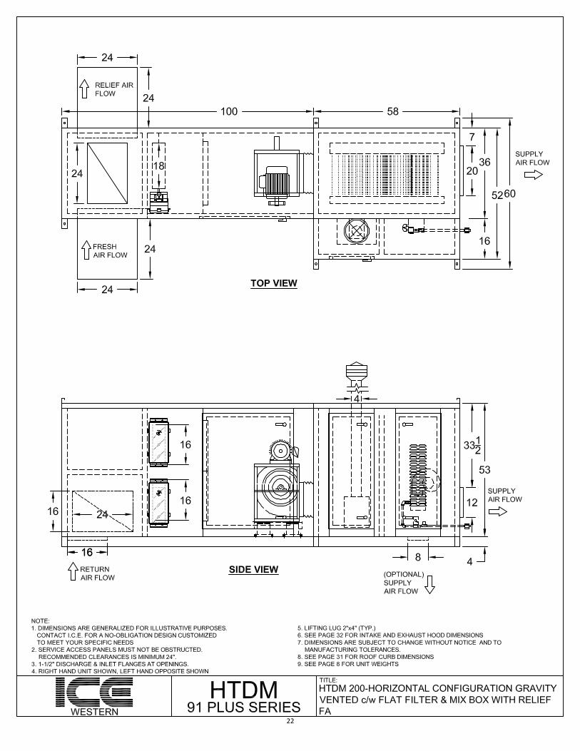
c/w FLAT FILTER & MIX BOX WITH RELIEF FA (HTDM 200) .................................................................... 22
c/w FLAT FILTER & MIX BOX WITH RELIEF FA, (HTDM 400-3000) .......................................................... 23
c/w FLAT FILTER,MIX BOX WITH RELIEF FA, COIL & RETURN BLOWER SECTION ................................... 24

For more information, please call 403-252-5577 ext. 222 or visit our website: www.icewestern.com
HTDM 91 PLUS DX SERIES ........................................................................................................................... 25
c/w FLAT FILTER, DX COIL, MIX BOX HORIZONTAL DISCHARGE & CONDENSER ..................................... 25
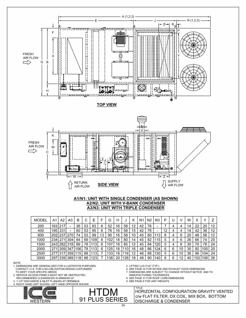
c/w FLAT FILTER, DX COIL, MIX BOX, BOTTOM DISCHARGE & CONDENSER .......................................... 26
c/w FLAT FILTER, DX COIL PLENUM HORIZONTAL DISCHARGE & CONDENSER ...................................... 27
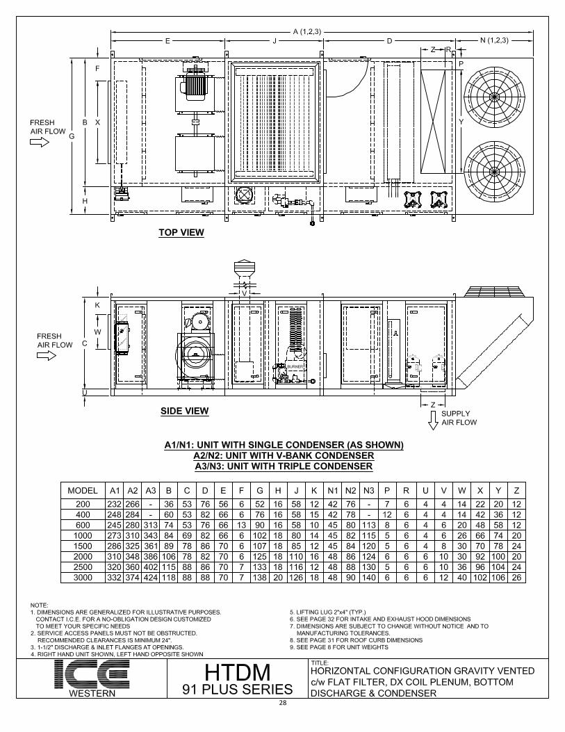
c/w FLAT FILTER, DX COIL PLENUM, BOTTOM DISCHARGE & CONDENSER ........................................... 28
c/w FLAT FILTER, DX COIL, MIX BOX WITH RELIEF FA & CONDENSER .................................................... 29
c/w FLAT FILTER, DX COIL, MIX BOX WITH RELIEF FA, RETURN BLOWER SECTION & CONDENSER ....... 30
CURB DETAIL DIMENSIONS ......................................................................................................................... 31
INLET HOOD DIMENSIONS .......................................................................................................................... 32
HTDM 91 PLUS TYPICAL SPECIFICATIONS ................................................................................................... 33
TYPE AND DESCRIPTION .......................................................................................................................... 33
CASING .................................................................................................................................................... 33
BLOWER/MOTOR SECTION ..................................................................................................................... 33
HEAT EXCHANGER ................................................................................................................................... 33
HEATING CONTROLS ............................................................................................................................... 33
COOLING CONTROLS ............................................................................................................................... 34
ELECTRICAL CONTROL EQUIPMENT ........................................................................................................ 34
DAMPERS & FILTER SECTION .................................................................................................................. 34
REMOTE CONTROL PANELS .................................................................................................................... 34
EVAPORATOR COILS ................................................................................................................................ 34
CONDENSER COILS .................................................................................................................................. 35
COMPRESSORS ........................................................................................................................................ 35
CONDENSER FANS ................................................................................................................................... 35
ICE WESTERN’S DX COOLING MODULATION .............................................................................................. 36
CUSTOM WIRING OPTIONS ......................................................................................................................... 37

DESIGN FEATURES:
HEATING ONLY:
• DRUM & TUBE HEAT EXCHANGER• 409 STAINLESS STEEL 14 GAUGE
HEAT EXCHANGER MATERIAL• PROPRIETARY TUBE
PLACEMENT/ARRANGEMENT• OMEGA AIR PATTERN• INTERNAL TURBULATORS INCREASE
HEAT TRANSFER
HEAT/COOL:
• HIGH EFFICIENT & DURABLE DIGITAL SCROLL D.X. COOLING WHICH ELIMINATES THE NEED FOR HOT- GAS BYPASS
• 10:1 TURNDOWN ON SINGLE STAGECOMPRESSORS AND 20:1 TURNDOWN FOR TANDEM COMPRESSORS
• VFD CONTROLLED CONDENSER FAN(NO FAN CYCLING)
• DIGITAL SUPERHEAT CONTROLLER• ELECTRONIC EXPANSION VALVE
OMEGA DESIGN
THE OMEGA HEAT EXCHANGER DESIGN PROVIDES A REVOLUTIONARY AIR PATTERNING OVER ALL THE CRITICALLY ESSENTIAL COMPONENTS OF THE HEAT EXCHANGER. THIS CONTINUAL “SCRUBBING” OF THE
HEAT EXCHANGER DRUM & TUBES ALLOWS FOR THE HIGHEST HEAT TRANSFER POSSIBLE.
THE OMEGA FLOW OF THE SUPPLY AIR HAS BEEN SHOWN TO ELIMINATE “HOT SPOT” AREAS OF THEHEAT EXCHANGER, ENSURING LONG HEAT EXCHANGER LIFE AND MAXIMUM HEAT TRANSFER. DURABLE 14
GAUGE 409 STAINLESS STEEL CONSTRUCTION OF THE ENTIRE HEAT EXCHANGER PROVIDES THE BEST MALEABLE EXPANSION AND CONTRACTION PROPERTIES DURING THE COMBUSTION PROCESS, THE HIGHEST POSSIBLE RESISTANCE TO CONDENSATE AND THE GREATEST CONDUCTIVITY OF HEAT TO
SUPPLY AIR. THIS ENSURES THE HIGHEST CAPACITIES AND EFFICIENCIES AVAILABLE.
For more information, please call 403-252-5577 ext. 222 or visit our website: www.icewestern.com 4
MVanRemmen
Rectangle
For more information, please call 403-252-5577 ext. 222 or visit our website: www.icewestern.com
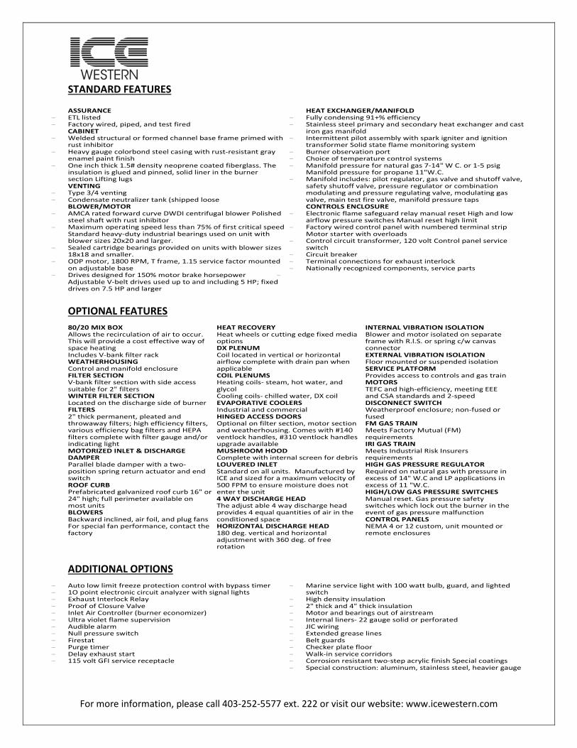
STANDARD FEATURES ASSURANCE
- ETL listed - Factory wired, piped, and test fired
CABINET - Welded structural or formed channel base frame primed with
rust inhibitor - Heavy gauge colorbond steel casing with rust-resistant gray
enamel paint finish - One inch thick 1.5# density neoprene coated fiberglass. The
insulation is glued and pinned, solid liner in the burner section Lifting lugs VENTING
- Type 3/4 venting - Condensate neutralizer tank (shipped loose
BLOWER/MOTOR - AMCA rated forward curve DWDI centrifugal blower Polished
steel shaft with rust inhibitor - Maximum operating speed less than 75% of first critical speed
Standard heavy-duty industrial bearings used on unit with blower sizes 20x20 and larger.
- Sealed cartridge bearings provided on units with blower sizes 18x18 and smaller.
- ODP motor, 1800 RPM, T frame, 1.15 service factor mounted on adjustable base
- Drives designed for 150% motor brake horsepower Adjustable V-belt drives used up to and including 5 HP; fixed drives on 7.5 HP and larger
HEAT EXCHANGER/MANIFOLD - Fully condensing 91+% efficiency - Stainless steel primary and secondary heat exchanger and cast
iron gas manifold - Intermittent pilot assembly with spark igniter and ignition
transformer Solid state flame monitoring system - Burner observation port - Choice of temperature control systems - Manifold pressure for natural gas 7-14" W C. or 1-5 psig
Manifold pressure for propane 11"W.C. - Manifold includes: pilot regulator, gas valve and shutoff valve,
safety shutoff valve, pressure regulator or combination modulating and pressure regulating valve, modulating gas valve, main test fire valve, manifold pressure taps CONTROLS ENCLOSURE
- Electronic flame safeguard relay manual reset High and low airflow pressure switches Manual reset high limit
- Factory wired control panel with numbered terminal strip Motor starter with overloads
- Control circuit transformer, 120 volt Control panel service switch
- Circuit breaker - Terminal connections for exhaust interlock - Nationally recognized components, service parts
-
OPTIONAL FEATURES 80/20 MIX BOX Allows the recirculation of air to occur. This will provide a cost effective way of space heating Includes V-bank filter rack WEATHERHOUSING Control and manifold enclosure FILTER SECTION V-bank filter section with side access suitable for 2" filters WINTER FILTER SECTION Located on the discharge side of burner FILTERS 2" thick permanent, pleated and throwaway filters; high efficiency filters, various efficiency bag filters and HEPA filters complete with filter gauge and/or indicating light MOTORIZED INLET & DISCHARGE DAMPER Parallel blade damper with a two-position spring return actuator and end switch ROOF CURB Prefabricated galvanized roof curb 16" or 24" high; full perimeter available on most units BLOWERS Backward inclined, air foil, and plug fans For special fan performance, contact the factory
HEAT RECOVERY Heat wheels or cutting edge fixed media options DX PLENUM Coil located in vertical or horizontal airflow complete with drain pan when applicable COIL PLENUMS Heating coils- steam, hot water, and glycol Cooling coils- chilled water, DX coil EVAPORATIVE COOLERS Industrial and commercial HINGED ACCESS DOORS Optional on filter section, motor section and weatherhousing. Comes with #140 ventlock handles, #310 ventlock handles upgrade available MUSHROOM HOOD Complete with internal screen for debris LOUVERED INLET Standard on all units. Manufactured by ICE and sized for a maximum velocity of 500 FPM to ensure moisture does not enter the unit 4 WAY DISCHARGE HEAD The adjust able 4 way discharge head provides 4 equal quantities of air in the conditioned space HORIZONTAL DISCHARGE HEAD 180 deg. vertical and horizontal adjustment with 360 deg. of free rotation
INTERNAL VIBRATION ISOLATION Blower and motor isolated on separate frame with R.l.S. or spring c/w canvas connector EXTERNAL VIBRATION ISOLATION Floor mounted or suspended isolation SERVICE PLATFORM Provides access to controls and gas train MOTORS TEFC and high-efficiency, meeting EEE and CSA standards and 2-speed DISCONNECT SWITCH Weatherproof enclosure; non-fused or fused FM GAS TRAIN Meets Factory Mutual (FM) requirements IRI GAS TRAIN Meets Industrial Risk Insurers requirements HIGH GAS PRESSURE REGULATOR Required on natural gas with pressure in excess of 14" W.C and LP applications in excess of 11 "W.C. HIGH/LOW GAS PRESSURE SWITCHES Manual reset. Gas pressure safety switches which lock out the burner in the event of gas pressure malfunction CONTROL PANELS NEMA 4 or 12 custom, unit mounted or remote enclosures
ADDITIONAL OPTIONS
- Auto low limit freeze protection control with bypass timer - 1O point electronic circuit analyzer with signal lights - Exhaust Interlock Relay - Proof of Closure Valve - Inlet Air Controller (burner economizer) - Ultra violet flame supervision - Audible alarm - Null pressure switch - Firestat - Purge timer - Delay exhaust start - 115 volt GFI service receptacle
- Marine service light with 100 watt bulb, guard, and lighted switch
- High density insulation - 2" thick and 4" thick insulation - Motor and bearings out of airstream - Internal liners- 22 gauge solid or perforated - JIC wiring - Extended grease lines - Belt guards - Checker plate floor - Walk-in service corridors - Corrosion resistant two-step acrylic finish Special coatings - Special construction: aluminum, stainless steel, heavier gauge

For more information, please call 403-252-5577 ext. 222 or visit our website: www.icewestern.com
COMPANY PROFILE
CREDIBILITY: ICE Western was founded in 1991 as a custom division of ICE MFG LTD in Winnipeg, Manitoba whose roots trace back to 1950.
Throughout the 1950’s the Company established a reputation for designing, manufacturing, and installing natural gas conversion burners to replace oil and coal fired furnaces. In 1961, ICE designed and built the first direct fired make-up air unit for the Canadian natural gas heating market.
More innovative new designs followed and the manufacturing of indirect fired units has continued for over 40 years. Constant improvement provides ICE customers with the next generation of heaters and industrial heating/cooling equipment. Many new products and inovations are on the horizon to meet the ever-increasing concern over cost, consumption and environmental impact.
With decades of proven experience, ICE offers a comprehensive product line of direct & indirect fired equipment with or with out integral packaged DX cooling. However, one size does not fit all, which is why ICE Western offers in house, custom design for any configuration of air-handling, heat recovery or process unit. Don’t hesitate to contact ICE Western to discuss a solution for your site-specific conditions.
CAPABILITY: Top management at ICE Western has over 25 years of HVAC and Refrigeration experience. With 300 employees, 3 production facilities and 50 + distributors, ICE units can be found on all types of buildings throughout Canada & the U.S.A. ICE Western has been servicing western Canada and the U.S.A. for over 25 years and now boasts a production facility on a 5 acre lot in Calgary with an extra 40,000 sqft. of brand new production space due online by Spring 2016.
With the addition of production at ICE Western, lead times for industrial cooling & heat recovery have dropped from 20 weeks to 12-14 weeks. A large, camera monitored and fence secured yard with ample storage, allows ICE Western to operate as a staging facility to hold units so that shipping can occur at the customer’s convenience.
QUALITY: Employees at ICE take great pride as manufacturers of HVAC equipment. ICE is committed to providing quality through every step of the operation with a quality control program that is equivalent to I.S.O. 9001. Every product is fully tested and inspected before delivery to ensure a high quality product. All models are approved according to The Standard for Gas Unit Heaters, Gas Packaged Heaters, Gas Utility Heaters, and Gas Fired Duct Furnaces: ANSI Z83.8/CSA 2.6 Issued 2013/04/01 and The Standard for Gas-Fired Appliances for Use at High Altitudes: CGA 2.17 Issued 1991/01/01. SERVICE: ICE provides qualified staff that can assist in on-site start-up and troubleshooting. PRICE: ICE offers some of the best pricing in the HVAC industry, and can match or surpass any competitor’s unit capabilities and quality commitments as well as meet or beat their delivery times.
CUSTOM UNITS: ICE provides custom built units to meet specifications and to exceed customer expectations. No job is too big or too difficult. Consult the in house design team for your custom needs.
For more information, please call 403-252-5577 ext. 222 or visit our website: www.icewestern.com
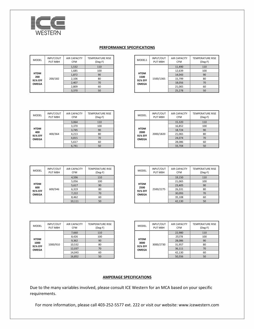
PERFORMANCE SPECIFICATIONS
MODEL INPUT/OUTPUT MBH
AIR CAPACITY CFM
TEMPERATURE RISE (Deg-F)
HTDM 200
91% EFF OMEGA
200/182
1,532 110 1,685 100 1,872 90 2,106 80 2,407 70 2,809 60 3,370 50
MODEL INPUT/OUTPUT MBH
AIR CAPACITY CFM
TEMPERATURE RISE (Deg-F)
HTDM 400
91% EFF OMEGA
400/364
3,064 110 3,370 100 3,745 90 4,213 80 4,815 70 5,617 60 6,741 50
MODEL INPUT/OUTPUT MBH
AIR CAPACITY CFM
TEMPERATURE RISE (Deg-F)
HTDM 600
91% EFF OMEGA
600/546
4,596 110 5,056 100 5,617 90 6,319 80 7,222 70 8,462 60
10,111 50
MODEL INPUT/OUTPUT MBH
AIR CAPACITY CFM
TEMPERATURE RISE (Deg-F)
HTDM 1000
91% EFF OMEGA
1000/910
7,660 110 8,426 100 9,362 90
10,532 80 12,037 70 14,043 60 16,852 50
MODEL1 INPUT/OUTPUT MBH
AIR CAPACITY CFM
TEMPERATURE RISE (Deg-F)
HTDM 1500
91% EFF OMEGA
1500/1365
11,490 110 12,639 100 14,043 90 15,799 80 18,056 70 21,065 60 25,278 50
MODEL INPUT/OUTPUT MBH
AIR CAPACITY CFM
TEMPERATURE RISE (Deg-F)
HTDM 2000
91% EFF OMEGA
2000/1820
15,320 110 16,852 100 18,724 90 21,065 80 24,074 70 28,086 60 33,704 50
MODEL INPUT/OUTPUT MBH
AIR CAPACITY CFM
TEMPERATURE RISE (Deg-F)
HTDM 2500
91% EFF OMEGA
2500/2275
19,150 110 21,065 100 23,405 90 26,331 80 30,093 70 35,108 60 42,130 50
MODEL INPUT/OUTPUT MBH
AIR CAPACITY CFM
TEMPERATURE RISE (Deg-F)
HTDM 3000
91% EFF OMEGA
3000/2730
22,980 110 25278 100 28,086 90 31,957 80 36,111 70 42,130 60 50,556 50
AMPERAGE SPECIFICATIONS Due to the many variables involved, please consult ICE Western for an MCA based on your specific requirements.
For more information, please call 403-252-5577 ext. 222 or visit our website: www.icewestern.com
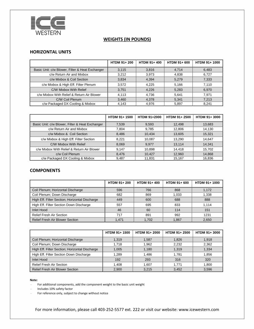
WEIGHTS (IN POUNDS) HORIZONTAL UNITS
HTDM 91+ 200 HTDM 91+ 400 HTDM 91+ 600 HTDM 91+ 1000
Basic Unit: c/w Blower, Filter & Heat Exchanger 3,115 3,816 4,714 6,483 c/w Return Air and Mixbox 3,212 3,973 4,838 6,727 c/w Mixbox & Coil Section 3,834 4,394 5,279 7,333
c/w Mixbox & High Eff. Filter Plenum 3,572 4,225 5,166 7,110 C/W Mixbox With Relief 3,751 4,226 5,283 6,970
c/w Mixbox With Relief & Return Air Blower 4,113 4,736 5,641 7,971 C/W Coil Plenum 3,460 4,378 5,341 7,213
c/w Packaged DX Cooling & Mixbox 4,143 4,976 5,897 8,241
HTDM 91+ 1500 HTDM 91+2000 HTDM 91+ 2500 HTDM 91+ 3000
Basic Unit: c/w Blower, Filter & Heat Exchanger 7,539 9,593 12,498 13,683 c/w Return Air and Mixbox 7,804 9,785 12,806 14,130 c/w Mixbox & Coil Section 8,486 10,434 13,605 15,321
c/w Mixbox & High Eff. Filter Section 8,221 10,087 13,290 14,647 C/W Mixbox With Relief 8,069 9,977 13,114 14,341
c/w Mixbox With Relief & Return Air Blower 9,147 10,898 14,418 15,702 c/w Coil Plenum 8,476 10,427 12,960 14,868
c/w Packaged DX Cooling & Mixbox 9,487 11,831 15,167 16,836
COMPONENTS
HTDM 91+ 200 HTDM 91+ 400 HTDM 91+ 600 HTDM 91+ 1000
Coil Plenum; Horizontal Discharge 596 766 868 1,172 Coil Plenum; Down Discharge 682 869 1,033 1,338 High Eff. Filter Section; Horizontal Discharge 449 600 688 888 High Eff. Filter Section Down Discharge 557 695 833 1,114 Inlet Hood 46 60 114 151 Relief Fresh Air Section 717 891 992 1231 Relief Fresh Air Blower Section 1,471 1,702 1,867 2,650
HTDM 91+ 1500 HTDM 91+ 2000 HTDM 91+ 2500 HTDM 91+ 3000
Coil Plenum; Horizontal Discharge 1,319 1,587 1,826 1,918 Coil Plenum; Down Discharge 1,718 1,962 2,232 2,362 High Eff. Filter Section; Horizontal Discharge 1,005 1,180 1,319 1,334 High Eff. Filter Section Down Discharge 1,289 1,486 1,781 1,856 Inlet Hood 192 293 316 320 Relief Fresh Air Section 1,408 1,607 1,771 1,800 Relief Fresh Air Blower Section 2,900 3,215 3,452 3,596
Note: - For additional components, add the component weight to the basic unit weight - Includes 10% safety factor - For reference only, subject to change without notice

For more information, please call 403-252-5577 ext. 222 or visit our website: www.icewestern.com
EFFICIENCIES AND TURNDOWNS
MODEL
HTDM 91+ EFFICIENCY TURNDOWNS
200 91% 23:1
400 91% 23:1
600 91% 29:1
1000 91% 50:1
1500 91% 60:1
2000 91% 60:1
2500 91% 60:1
3000 91% 60:1
STATIC PRESSURE DROP(S) DUE TO ACCESSORIES
ACCESSORIES STATIC PRESSURE DROP (IN
INCHES WATER)
Flat and v-Bank Filter Section 0.4
Louvered Inlet Hood 0.1
Evaporative Cooler (Commercial) 0.3
Evaporative Cooler (Industrial) 0.4
Inlet Damper 0.1
DX Plenum & Coil 0.6
80/20 Mixbox w/ Filters 0.7 Horizontal Discharge Head 0.5
High Eff. Filter Section 1.0
Heat Coil 0.2
Fixed Media Heat Recovery 1.0
Note: Accessory static pressure drops are calculated at maximum CFM loads
STANDARD FILTER SECTION SUMMARY
MODEL HTDM 91+
QUANTITY – SIZE INCHES
TOTAL FILTER FREE AREA ft²
MAXIMUM AIR FLOW CFM
200 2-16x25x2 5.26 2,780
400 4-16x25x2 11.1 5,550
600 3-16x20x2 3-20x20x2 15 7,500
1000 4-20x25x2 4-20x20x2 25 12,500
1500 12-16x25x2 33.3 16,500
2000 12-24x24x2 48 24,000
2500 16-25x20x2 55.6 27,500
3000 12-25x20x2 8-25x16x2 63.9 32,000
General Filter Performance Notes:
-The standard filter section may contain one of the following three types: - Replaceable: 2 inch fiberglass media with an average efficiency of 20% at 500 fpm. - Throwaway: 2 inch pleated media with an average efficiency of 30% at 500 fpm. - Permanent: 2 inch media with layers of silt and expanded aluminum. The media efficiency averages 20% at 500 fpm. The
media can be cleaned using a stream of water.
Note: - The static pressure drop through the filters is approximately 0.4” W.C. (clean) and approximately 0.8” W.C. (dirty) - The maximum airflow is calculated so that the velocity across the filters never exceeds 500 fpm - A V-bank filter section is required on the HTDM 91+ 1000 and 1500 when the temperature rise is less than 70°F

For more information, please call 403-252-5577 ext. 222 or visit our website: www.icewestern.com
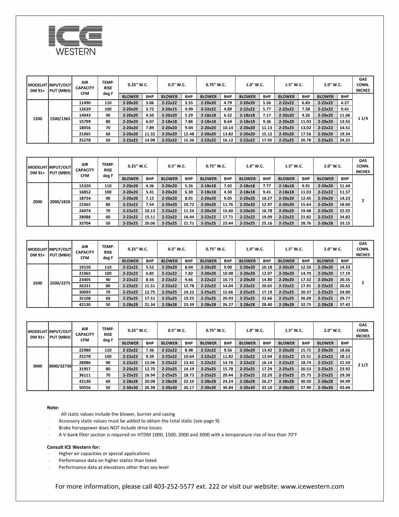
HTDM 91 PLUS PERFORMANCE SPECIFICATIONS
MODELHTDM 91+
INPUT/OUTPUT (MBH)
AIR CAPACITY
CFM
TEMP. RISE deg F
0.25” W.C. 0.5” W.C. 0.75” W.C. 1.0” W.C. 1.5” W.C. 2.0” W.C. GAS
CONN. INCHES
BLOWER BHP BLOWER BHP BLOWER BHP BLOWER BHP BLOWER BHP BLOWER BHP
1 200 200/182
1532 110 9x9 0.40 9x9 0.49 9x7 0.76 9x7 0.85 9x7 1.03 9X7 1.21- 1685 100 9x9 0.50 9x7 0.94 9x7 1.04 9x7 1.02 9x7 1.22 9x7 1.42 1872 90 9x9 0.63 9x9 0.73 9x7 1.15 9x7 1.26 9x7 1.48 9x7 1.70 2106 80 9x9 0.82 9x9 0.92 9x9 1.03 9x9 1.54 12x9 1.33 12x9 1.47 2407 70 10x10 0.85 9x9 1.30 9x9 1.42 9x9 1.54 9x9 1.81 12x9 1.72 2809 60 10x10 1.49 10x10 1.65 10x10 1.79 10x10 1.95 12x12 2.19 12x9 2.57 3370 50 12x9 1.70 12x9 1.85 12x9 2.01 12x9 2.16 12x12 2.65 12x12 3.30
MODELHTDM 91+
INPUT/OUTPUT (MBH)
AIR CAPACITY
CFM
TEMP. RISE deg F
0.25” W.C. 0.5” W.C. 0.75” W.C. 1.0” W.C. 1.5” W.C. 2.0” W.C. GAS
CONN. INCHES
BLOWER BHP BLOWER BHP BLOWER BHP BLOWER BHP BLOWER BHP BLOWER BHP
1 400 400/364
3064 110 12x12 0.89 12x9 1.25 12x9 1.35 12x9 1.49 10x10 2.21 10x10 2.56 3370 100 12x12 1.08 12x12 1.27 12x9 1.69 12x9 1.80 12x9 2.11 12x9 2.43 3745 90 12x12 1.39 12x12 1.58 12x12 1.89 12x12 2.01 12x12 2.44 18x18 3.03 4213 80 12x12 1.82 12x12 2.03 12x12 2.25 12x12 2.60 18x18 2.15 18x18 3.37 4815 70 15z15 1.76 15z15 1.99 15z11 2.30 15z11 2.53 18z18 3.17 18z18 3.89 5617 60 15z15 2.56 18x13 2.75 18x13 3.03 18x13 3.33 18x18 3.90 18x18 4.07 6741 50 18x18 2.61 20x20 3.57 20x20 4.05 18x13 4.48 18x13 5.53 18x18 6.05
MODELHTDM 91+
INPUT/OUTPUT (MBH)
AIR CAPACITY
CFM
TEMP. RISE deg F
0.25” W.C. 0.5” W.C. 0.75” W.C. 1.0” W.C. 1.5” W.C. 2.0” W.C. GAS
CONN. INCHES
BLOWER BHP BLOWER BHP BLOWER BHP BLOWER BHP BLOWER BHP BLOWER BHP
1 600 600/546
4596 110 15x15 1.30 15x15 1.55 15x11 1.9 15x11 2.05 12x12 3.17 12x12 3.71 5056 100 15x15 1.68 15x15 1.92 15x15 2.14 15x15 2.42 18x18 2.92 18x18 3.65 5617 90 15x15 2.12 15x15 2.40 15x15 2.66 15x15 2.91 22x22 3.34 20x15 4.34 6319 80 18x18 2.10 18x18 2.40 18x18 2.71 20x15 3.30 18x13 4.26 18x13 4.91 7222 70 18x18 2.83 18x18 3.20 18x18 3.53 18x18 3.07 20x15 5.03 20x20 5.87 8462 60 18x18 4.13 18x18 4.57 18x18 4.99 18x18 5.39 20x15 6.67 22x15 8.61
10111 50 20x18 4.38 20x18 5.03 20x18 5.62 20x18 6.22 20x20 7.71 22x15 8.61
MODELHTDM 91+
INPUT/OUTPUT (MBH)
AIR CAPACITY
CFM
TEMP. RISE deg F
0.25” W.C. 0.5” W.C. 0.75” W.C. 1.0” W.C. 1.5” W.C. 2.0” W.C. GAS
CONN. INCHES
BLOWER BHP BLOWER BHP BLOWER BHP BLOWER BHP BLOWER BHP BLOWER BHP
1 1/4 1000 1000/910
7660 110 2-1x12 2.96 2-1x12 3.36 2-1x12 3.79 2-1x12 4.24 2-15x15 4.90 2-18x18 6.05 8426 100 2-1x12 3.66 2-1x12 4.09 2-1x12 4.53 2-1x12 4.91 2-1x12 5.98 2-18x18 6.79 9362 90 2-20x20 3.11 2-22x22 3.44 2-22x22 4.14 2-22x22 4.83 2-18x18 6.07 2-18x18 7.50
10532 80 2-20x20 3.54 2-20x20 4.26 2-22x22 4.71 2-22x22 5.48 2-22x22 7.07 2-18x18 8.39 12037 70 2-25x25 4.26 2-15x15 6.34 2-15x15 6.89 2-22x22 6.44 2-22x22 8.40 2-22x22 10.66 14043 60 2-18x18 6.25 2-18x18 6.89 2-22x22 7.10 2-20x20 8.89 2-20x20 10.73 2-22x22 12.11 16852 50 2-18x18 9.54 2-18x18 10.37 2-18x18 11.17 2-18x18 11.93 2-20x20 14.22 2-20x20 16.64
Note: - All static values include the blower, burner and casing- Accessory static values must be added to obtain the total static (see page 9) - Brake horsepower does NOT include drive losses- A V-bank filter section is required on HTDM 1000, 1500, 2000 and 3000 with a temperature rise of less than 70°F
Consult ICE Western for: - Higher air capacities or special applications- Performance data on higher statics than listed- Performance data at elevations other than sea level
For more information, please call 403-252-5577 ext. 222 or visit our website: www.icewestern.com
MODELHTDM 91+
INPUT/OUTPUT (MBH)
AIR CAPACITY
CFM
TEMP. RISE deg F
0.25” W.C. 0.5” W.C. 0.75” W.C. 1.0” W.C. 1.5” W.C. 2.0” W.C. GAS
CONN. INCHES
BLOWER BHP BLOWER BHP BLOWER BHP BLOWER BHP BLOWER BHP BLOWER BHP
1 1/4 1500 1500/1365
11490 110 2-20x20 3.06 2-22x22 3.55 2-20x20 4.79 2-20x20 5.56 2-22x22 6.83 2-22x22 4.27 12639 100 2-20x20 3.72 2-20x15 4.99 2-22x22 4.89 2-22x22 5.77 2-22x22 7.58 2-22x22 9.41 14043 90 2-20x20 4.50 2-20x20 5.29 2-18x18 6.52 2-18x18 7.17 2-20x20 9.26 2-20x20 11.06 15799 80 2-20x20 6.07 2-18x18 7.86 2-18x18 8.64 2-18x18 9.36 2-20x20 11.03 2-20x20 13.55 18056 70 2-20x20 7.89 2-20x20 9.04 2-20x20 10.14 2-20x20 11.13 2-25x25 13.02 2-22x22 14.51 21065 60 2-20x20 11.32 2-20x20 12.48 2-20x20 13.82 2-20x20 15.12 2-20x20 17.56 2-20x20 19.34 25278 50 2-22x22 14.08 2-22x22 15.36 2-22x22 16.12 2-22x22 17.95 2-25x25 20.78 2-25x25 24.25
MODELHTDM 91+
INPUT/OUTPUT (MBH)
AIR CAPACITY
CFM
TEMP. RISE deg F
0.25” W.C. 0.5” W.C. 0.75” W.C. 1.0” W.C. 1.5” W.C. 2.0” W.C. GAS
CONN. INCHES
BLOWER BHP BLOWER BHP BLOWER BHP BLOWER BHP BLOWER BHP BLOWER BHP
2 2000 2000/1820
15320 110 2-20x20 4.36 2-20x20 5.26 2-18x18 7.02 2-18x18 7.77 2-18x18 9.91 2-20x20 11.44 16852 100 2-20x20 5.41 2-20x20 6.30 2-18x18 4.30 2-18x18 9.41 2-18x18 11.03 2-22x22 11.57 18724 90 2-20x20 7.12 2-20x20 8.01 2-20x20 9.05 2-20x20 10.27 2-20x20 12.45 2-20x20 14.23 21065 80 2-22x22 7.54 2-20x20 10.72 2-20x20 11.76 2-20x20 12.97 2-20x20 15.64 2-20x20 18.00 24074 70 2-22x22 10.13 2-22x22 11.24 2-20x20 15.60 2-20x20 16.78 2-20x20 19.48 2-20x20 22.55 28086 60 2-22x22 15.11 2-22x22 16.44 2-22x22 17.71 2-22x22 19.09 2-22x22 21.82 2-22x22 24.82 33704 50 2-25x25 20.06 2-25x25 21.71 2-25x25 23.44 2-25x25 25.16 2-25x25 28.76 2-28x28 33.15
MODELHTDM 91+
INPUT/OUTPUT (MBH)
AIR CAPACITY
CFM
TEMP. RISE deg F
0.25” W.C. 0.5” W.C. 0.75” W.C. 1.0” W.C. 1.5” W.C. 2.0” W.C. GAS
CONN. INCHES
BLOWER BHP BLOWER BHP BLOWER BHP BLOWER BHP BLOWER BHP BLOWER BHP
2 2500 2500/2275
19150 110 2-22x22 5.52 2-20x20 8.04 2-20x20 9.00 2-20x20 10.18 2-20x20 12.56 2-20x20 14.33 21065 100 2-22x22 6.85 2-22x22 7.82 2-20x20 10.98 2-20x20 12.07 2-20x20 14.70 2-20x20 17.19 23405 90 2-22x22 8.56 2-22x22 9.66 2-22x22 10.73 2-20x20 14.80 2-20x20 17.32 2-20x20 20.35 26331 80 2-22x22 11.51 2-22x22 12.78 2-22x22 14.04 2-22x22 20.65 2-22x22 17.91 2-22x22 20.65 30093 70 2-25x25 12.75 2-25x25 14.22 2-25x25 15.66 2-25x25 17.19 2-25x25 20.37 2-25x25 24.00 35108 60 2-25x25 17.51 2-25x25 19.25 2-25x25 20.93 2-25x25 22.66 2-25x25 26.09 2-25x25 29.77 42130 50 2-28x28 21.34 2-28x28 23.39 2-28x28 26.27 2-28x28 28.40 2-28x28 32.75 2-28x28 37.42
MODELHTDM 91+
INPUT/OUTPUT (MBH)
AIR CAPACITY
CFM
TEMP. RISE deg F
0.25” W.C. 0.5” W.C. 0.75” W.C. 1.0” W.C. 1.5” W.C. 2.0” W.C. GAS
CONN. INCHES
BLOWER BHP BLOWER BHP BLOWER BHP BLOWER BHP BLOWER BHP BLOWER BHP
2 1/2 3000 3000/32730
22980 110 2-22x22 7.36 2-22x22 8.48 2-22x22 9.56 2-20x20 13.42 2-20x20 15.72 2-20x20 18.66 25278 100 2-22x22 9.39 2-22x22 10.64 2-22x22 11.82 2-22x22 13.04 2-22x22 15.51 2-22x22 18.13 28086 90 2-22x22 12.06 2-22x22 13.42 2-22x22 14.76 2-22x22 16.14 2-22x22 18.74 2-22x22 21.50 31957 80 2-25x25 12.70 2-25x25 14.19 2-25x25 15.78 2-25x25 17.29 2-25x25 20.53 2-25x25 23.92 36111 70 2-25x25 16.94 2-25x25 18.73 2-25x25 20.44 2-25x25 22.20 2-25x25 25.75 2-25x25 29.30 42130 60 2-28x28 20.08 2-28x28 22.10 2-28x28 24.24 2-28x28 26.27 2-28x28 30.50 2-28x28 34.99 50556 50 2-30x30 26.38 2-30x30 26.17 2-30x30 30.84 2-30x30 33.10 2-30x30 37.90 2-30x30 43.04
Note: - All static values include the blower, burner and casing- Accessory static values must be added to obtain the total static (see page 9) - Brake horsepower does NOT include drive losses- A V-bank filter section is required on HTDM 1000, 1500, 2000 and 3000 with a temperature rise of less than 70°F
Consult ICE Western for: - Higher air capacities or special applications- Performance data on higher statics than listed- Performance data at elevations other than sea level

For more information, please call 403-252-5577 ext. 222 or visit our website: www.icewestern.com
COOLING PERFORMANCE DATA
DX5S Available Stages of Cooling: 1 DX6S Available Stages of Cooling: 1 DX7.5S Available Stages of Cooling: 1
SST (°F)
Air Temperature Entering Condenser (°F) SST (°F)
Air Temperature Entering Condenser (°F) SST (°F)
Air Temperature Entering Condenser (°F)
75 85 95 105 115 80 95 100 105 115 80 95 100 105 115
40 TC CDT
57.8 99.3
55.1 110.0
52.2 120.0
49.2 130.0
46.1 140.0 40 TC
CDT 77.4 111
69.8 124
67.3 128
64.7 132
59.6 141 40 TC
CDT 97.5 109
88.0 120
84.8 127
81.7 131
75.3 140
45 TC CDT
63.0 101.0
60.0 111.0
57.0 121.0
53.8 132.0
50.5 142.0 45 TC
CDT 84.9 114
77.0 126
74.4 131
71.7 135
66.4 143 45 TC
CDT 107.0 111
97.0 124
93.6 129
90.2 133
83.4 142
50 TC CDT
68.5 102.0
65.3 113.0
62.1 123.0
58.7 133.0
55.2 143.0 50 TC
CDT 92.7 116
84.5 129
81.7 133
78.9 138
73.4 146 50 TC
CDT 117.0 114
106.0 127
103.0 131
99.2 136
92.0 144
DX10S Available Stages of Cooling: 1, 2 DX10.5S Available Stages of Cooling: 1, 2, 3, 4 DX12.5S Available Stages of Cooling: 1, 2, 3, 4
SST (°F)
Air Temperature Entering Condenser (°F) SST (°F)
Air Temperature Entering Condenser (°F) SST (°F)
Air Temperature Entering Condenser (°F)
80 95 100 105 115 85 95 100 105 115 80 95 100 105 115
40 TC CDT
119.0 115
107.0 127
102.0 132
98.4 136
90.3 145 40 TC
CDT 117.0 115
109.0 124
105.0 128
101.0 133
93.0 142 40 TC
CDT 145.0 112
135.0 121
131.0 126
126.0 130
117.0 140
45 TC CDT
130.0 118
117.0 130
113.0 134
109.0 139
100.0 147 45 TC
CDT 129.0 117
120.0 126
116.0 131
111.0 135
103.0 144 45 TC
CDT 159.0 114
149.0 123
144.0 127
139.0 132
130.0 141
50 TC CDT
142.0 121
128.0 133
124.0 137
119.0 141
110.0 150 50 TC
CDT 141.0 120
132.0 129
127.0 133
122.0 137
113.0 146 50 TC
CDT 174.0 116
164.0 124
159.0 129
153.0 134
143.0 143
DX15S Available Stages of Cooling: 1, 2, 3, 4 DX20S Available Stages of Cooling: 2, 3 DX25S Available Stages of Cooling: 2, 3, 4
SST (°F)
Air Temperature Entering Condenser (°F) SST (°F)
Air Temperature Entering Condenser (°F) SST (°F)
Air Temperature Entering Condenser (°F)
80 95 100 105 115 80 95 100 105 115 80 95 100 105 115
40 TC CDT
187.0 117
176.0 126
170.0 130
165.0 135
154.0 144 40 TC
CDT 251.0 117
255.0 129
217.0 133
208.0 137
191.0 146 40 TC
CDT 333.0 115
301.0 128
290.0 133
279.0 137
258.0 145
45 TC CDT
204.0 119
192.0 128
186.0 133
180.0 137
168.0 146 45 TC
CDT 275.0 121
248.0 133
239.0 137
230.0 141
212.0 149 45 TC
CDT 365.0 118
330.0 131
319.0 135
307.0 140
284.0 148
50 TC CDT
222.0 122
209.0 131
203.0 135
197.0 140
184.0 148 50 TC
CDT 299.0 124
271.0 136
262.0 140
252.0 144
232.0 152 50 TC
CDT 398.0 121
361.0 134
348.0 138
336.0 142
312.0 151
DX30S Available Stages of Cooling: 2, 3, 4 DX40S Available Stages of Cooling: 2, 3, 4 DX50T Available Stages of Cooling: 4, 6, 8
SST (°F)
Air Temperature Entering Condenser SST (°F)
Air Temperature Entering Condenser SST (°F)
Air Temperature Entering Condenser
80 95 100 105 115 80 95 100 105 115 85 95 100 105 115
40 TC CDT
371.0 115
337.0 128
326.0 132
314.0 136
292.0 145 40 TC
CDT 503.0 111
461.0 124
447.0 129
433.0 133
405.0 142 40 TC
CDT 568.0 116
527.0 125
506.0 130
486.0 135
44.0 144
45 TC CDT
405.0 117
369.0 130
357.0 135
345.0 139
321.0 147 45 TC
CDT 551.0 114
505.0 127
489.0 131
474.0 136
444.0 145 45 TC
CDT 627.0 119
583.0 127
561.0 132
540.0 137
496.0 146
50 TC CDT
440.0 120
402.0 133
390.0 138
377.0 142
351.0 150 50 TC
CDT 599.0 116
550.0 129
534.0 134
518.0 138
485.0 147 50 TC
CDT 688.0 121
642.0 130
619.0 134
595.0 139
- -
DX60T Available Stages of Cooling: 4, 6, 8 DX70T Available Stages of Cooling: 4, 6, 8 DX80T Available Stages of Cooling: 4, 6, 8
SST (°F)
Air Temperature Entering Condenser (°F) SST (°F)
Air Temperature Entering Condenser (°F) SST (°F)
Air Temperature Entering Condenser (°F)
85 95 100 105 115 80 95 100 105 115 85 95 100 105 115
40 TC CDT
682.0 116
634.0 125
611.0 130
588.0 135
541.0 144 40 TC
CDT 829.0 115
778.0 124
753.0 129
727.0 133
677.0 143 40 TC
CDT 954.0 117
896.0 126
866.0 131
838.0 136
780.0 145
45 TC CDT
749.0 118
699.0 127
674.0 132
650.0 136
600.0 146 45 TC
CDT 910.0 118
854.0 127
827.0 131
800.0 136
745.0 145 45 TC
CDT 1047.0
119 984.0 128
953.0 128
922.0 138
860.0 147
50 TC CDT
822.0 120
768.0 130
741.0 134
715.0 139
662.0 148 50 TC
CDT 994.0 120
935.0 129
905.0 133
876.0 138
817.0 147 50 TC
CDT 1144.0
122 1077.0
131 1044.0
135 1011.0
140 944.0 149
Nomenclature:
DX 20 S ↓ ↘
Nominal S – Single Compressor Tonnage T – Twin Compressor
SST -Saturated Suction Temperature (°F) TC - Gross Cooling Capacity (°F) CDT - Saturated Discharge Temperature at Compressor (°F)
For capacities larger than or between those indicated or for capacities of twin compressor units less than 50 tons, consult ICE Western. For reference only, subject to change without notice.

13

14

15

16

17

18

19

20

21
22

23

24

25
26

27
28

29

30

31

32

For more information, please call 403-252-5577 ext. 222 or visit our website: www.icewestern.com
HTDM 91 PLUS TYPICAL SPECIFICATIONS TYPE AND DESCRIPTION Furnish an I.C.E HTDM DX Model indirect fired self-contained make-up air unit with packaged cooling in accordance with the following specifications. The unit shall be ETL and CETL certified.
The heater shall be designed to ensure 91Plus efficiency at full firing rate and the power burner has a turndown capacity between 23:1 and 60:1 depending on the HTDM selection. The heat exchanger and blower shall be constructed so they can easily be disassembled and reassembled in the field if necessary. The unit shall be equipped to operate from a single point power connection. The heater shall be flame tested before shipment and the manufacturer shall keep a detailed flame test report on file. Factory testing shall be confirmed with a combustion analyzer and flow meter. The heater shall be shipped completely factory assembled and wired including all pre-piped manifold components and fuses, ready for immediate power and fuel connections.
CASING The unit exterior casing shall be heavy gauge G90 rated bonderized steel. Unit roof shall feature standing seam construction. The entire unit casing shall be insulated with 1-in. thick 1.5-lb. (2-in. thick 1.5-lb.) fiberglass insulation with hard neoprene backing in a sandwich wall fashion (22-gauge solid liner). The unit exterior shall be finished with industrial enamel (catalyzed epoxy) paint. An integral welded iron channel frame shall support the unit casing. The structural iron frame shall be sandblasted, primed and finished with industrial enamel (catalyzed epoxy) paint.
BLOWER/MOTOR SECTION The fan section and motor assembly shall be constructed in accordance with the requirements of the Air Moving and Conditioning Association (AMCA). The assembly shall be designed to house the fan(s), bearings, motor, and v-belts, which shall be selected for at least 50% above the rated motor capacity. The fan(s) and motor shall be mounted on a welded unitary base made of angle iron frame. The frame shall be sandblasted, primed and finished with industrial enamel (catalyzed epoxy) paint. The unitary base shall be provided with seismic spring vibration isolation. The blower section shall have a hinged access door with Austin Romtech handles to allow easy maintenance of filters and belts. The NEMA T-Frame motor shall be mounted on an adjustable base located within the fan section. The blower shall be a forward curve DWDI centrifugal blower. The blower wheel shall be statically and dynamically balanced, and mounted on a turned, ground and polished shaft with rigid bearing supports. The shaft shall be designed with a maximum operating speed not exceeding 75% of the first critical speed. The bearings shall be split taper lock ball bearing type L20 minimum life of 100,000 hours (L10 200 kHr).
Fan performance shall be based on tests conducted in accordance with AMCA Standard Test Code for Air moving Devices. (All fans shall have sharply rising pressure characteristic extending throughout the operating range and continuing to rise well beyond the efficiency peak to assure quiet and stable operation under all conditions. Horsepower characteristics shall be truly non-overloading and shall reach a peak in the normal selection area.) Fan manufacturer shall provide sound power ratings in the eight octave bands, which shall be based on AMCA Standard 300-67, test, setup number one. Sound power ratings shall be referenced 10-12 watts. A factory dynamic balance shall be made on all fans after their assembly. An IRD or PMC analyzer shall be used to measure velocity, and the final reading shall not exceed 0.1 inches per second. The exact level of vibration shall be recorded on the fan as proof of the final dynamic balance at the factory.
HEAT EXCHANGER The heat exchanger shall be of multiple pass design, made up of at least 16-gauge stainless steel drum and tubes. The primary and secondary heat transfer surfaces shall be constructed of Type 409 series stainless steel, with internal stainless steel high efficiency enhancing baffles. The stainless steel tubes shall be continuously welded into the secondary front and rear header tube sheets to ensure an airtight seal. After welding, the heat exchanger shall be pressure tested to 20 psi to ensure that there are no leaks. Manufacturer shall provide complete pressure testing report with Installation Manual. Failure to provide this report will result in a 10% holdback. Units shall be provided with multiple condensate drains. The heat exchanger section shall have an internal radiation shield to maintain a jacket loss of less than 2% of rated output. All heat transfer surfaces, including headers and the front collector box, shall be inside the casing and in the airstream. The construction of the heat exchanger shall permit free, unrestricted lateral, vertical, and peripheral expansion during the heating and cooling cycle without damage or strain to any parts. The burner shall be constructed with at least 14-gauge stainless steel and with the air baffles being made up of 430 stainless steel to ensure high durability and life of the burner. The burner assembly shall be a blow through positive pressure type with an intermittent pilot ignition system. Flame supervision shall be with a solid state programmed flame relay complete with flame rod. The unit’s burner motor and modulating gas valve must be electronically controlled to guarantee, to the customer, a highly efficient unit at all times and applications. The unit efficiency shall be 91Plus through the entire operating range depending on which HTDM selection is used and shall be independently tested and verified by ETL. The main and pilot manifolds shall be completely factory pre-piped to the burner. This assembly must be factory wired and include the following minimum components: main and pilot manual shut-off valves, main and pilot regulators, main and pilot automatic shut-off valves and adequate union and test ports for unconstrained service. HTDM 200, 400 and 600 indoor units can be vented using type B vent without a draft hood. HTDM 1000 and 1500 indoor units can be vented using type B vent with a diverter to assure safety and guarantee that all combustible gases leave the unit. There must also be a means of collecting and disposal of condensate formed in the flue gas by means of a 409 stainless steel flue box with drain and heat exchanger drain. Drains shall be made of stainless steel tubing. The flue chimney will be made of stainless steel.
HEATING CONTROLS Units must be controlled electronically to achieve a turndown of at least 23:1 and to guarantee the heat exchanger efficiencies of at least 91Plus. Unit controller must be a true proportional integral decay (PID) controller to maintain the turndown and unit efficiencies. The controller must be able to electronically adjust the burner blower and modulating gas valve to maintain ideal combustion levels and shall monitor the amount of combustion air available to guarantee proper emission standards. Unit control will consist of a highly accurate feedback control system. Corrective action in this system is taken only when the balance has been upset due to a change in the disturbance variable. Any other control that does not behave in this manner is unacceptable. The ICECON III controller analyzes the process and calculates a control error from the measured values. Continuous cycling of the burner or blower is unacceptable. The proportional control in the ICECON III controller will provide an output signal in proportion to the size of the control error. If the control error persists, the output will continue to ramp in the correct direction, until the control error is eliminated.
For more information, please call 403-252-5577 ext. 222 or visit our website: www.icewestern.com
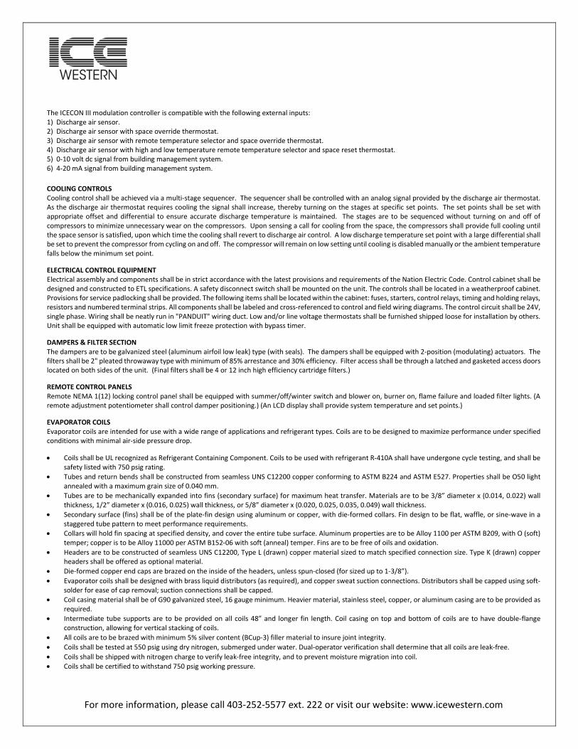
The ICECON III modulation controller is compatible with the following external inputs: 1) Discharge air sensor. 2) Discharge air sensor with space override thermostat. 3) Discharge air sensor with remote temperature selector and space override thermostat. 4) Discharge air sensor with high and low temperature remote temperature selector and space reset thermostat. 5) 0-10 volt dc signal from building management system. 6) 4-20 mA signal from building management system. COOLING CONTROLS Cooling control shall be achieved via a multi-stage sequencer. The sequencer shall be controlled with an analog signal provided by the discharge air thermostat. As the discharge air thermostat requires cooling the signal shall increase, thereby turning on the stages at specific set points. The set points shall be set with appropriate offset and differential to ensure accurate discharge temperature is maintained. The stages are to be sequenced without turning on and off of compressors to minimize unnecessary wear on the compressors. Upon sensing a call for cooling from the space, the compressors shall provide full cooling until the space sensor is satisfied, upon which time the cooling shall revert to discharge air control. A low discharge temperature set point with a large differential shall be set to prevent the compressor from cycling on and off. The compressor will remain on low setting until cooling is disabled manually or the ambient temperature falls below the minimum set point.
ELECTRICAL CONTROL EQUIPMENT Electrical assembly and components shall be in strict accordance with the latest provisions and requirements of the Nation Electric Code. Control cabinet shall be designed and constructed to ETL specifications. A safety disconnect switch shall be mounted on the unit. The controls shall be located in a weatherproof cabinet. Provisions for service padlocking shall be provided. The following items shall be located within the cabinet: fuses, starters, control relays, timing and holding relays, resistors and numbered terminal strips. All components shall be labeled and cross-referenced to control and field wiring diagrams. The control circuit shall be 24V, single phase. Wiring shall be neatly run in "PANDUIT" wiring duct. Low and/or line voltage thermostats shall be furnished shipped loose for installation by others. Unit shall be equipped with automatic low limit freeze protection with bypass timer.
DAMPERS & FILTER SECTION The dampers are to be galvanized steel (aluminum airfoil low leak) type (with seals). The dampers shall be equipped with 2-position (modulating) actuators. The filters shall be 2" pleated throwaway type with minimum of 85% arrestance and 30% efficiency. Filter access shall be through a latched and gasketed access doors located on both sides of the unit. (Final filters shall be 4 or 12 inch high efficiency cartridge filters.)
REMOTE CONTROL PANELS Remote NEMA 1(12) locking control panel shall be equipped with summer/off/winter switch and blower on, burner on, flame failure and loaded filter lights. (A remote adjustment potentiometer shall control damper positioning.) (An LCD display shall provide system temperature and set points.)
EVAPORATOR COILS Evaporator coils are intended for use with a wide range of applications and refrigerant types. Coils are to be designed to maximize performance under specified conditions with minimal air-side pressure drop.
• Coils shall be UL recognized as Refrigerant Containing Component. Coils to be used with refrigerant R-410A shall have undergone cycle testing, and shall be safety listed with 750 psig rating.
• Tubes and return bends shall be constructed from seamless UNS C12200 copper conforming to ASTM B224 and ASTM E527. Properties shall be O50 light annealed with a maximum grain size of 0.040 mm.
• Tubes are to be mechanically expanded into fins (secondary surface) for maximum heat transfer. Materials are to be 3/8” diameter x (0.014, 0.022) wall thickness, 1/2” diameter x (0.016, 0.025) wall thickness, or 5/8” diameter x (0.020, 0.025, 0.035, 0.049) wall thickness.
• Secondary surface (fins) shall be of the plate-fin design using aluminum or copper, with die-formed collars. Fin design to be flat, waffle, or sine-wave in a staggered tube pattern to meet performance requirements.
• Collars will hold fin spacing at specified density, and cover the entire tube surface. Aluminum properties are to be Alloy 1100 per ASTM B209, with O (soft) temper; copper is to be Alloy 11000 per ASTM B152-06 with soft (anneal) temper. Fins are to be free of oils and oxidation.
• Headers are to be constructed of seamless UNS C12200, Type L (drawn) copper material sized to match specified connection size. Type K (drawn) copper headers shall be offered as optional material.
• Die-formed copper end caps are brazed on the inside of the headers, unless spun-closed (for sized up to 1-3/8”). • Evaporator coils shall be designed with brass liquid distributors (as required), and copper sweat suction connections. Distributors shall be capped using soft-
solder for ease of cap removal; suction connections shall be capped. • Coil casing material shall be of G90 galvanized steel, 16 gauge minimum. Heavier material, stainless steel, copper, or aluminum casing are to be provided as
required. • Intermediate tube supports are to be provided on all coils 48” and longer fin length. Coil casing on top and bottom of coils are to have double-flange
construction, allowing for vertical stacking of coils. • All coils are to be brazed with minimum 5% silver content (BCup-3) filler material to insure joint integrity. • Coils shall be tested at 550 psig using dry nitrogen, submerged under water. Dual-operator verification shall determine that all coils are leak-free. • Coils shall be shipped with nitrogen charge to verify leak-free integrity, and to prevent moisture migration into coil. • Coils shall be certified to withstand 750 psig working pressure.

For more information, please call 403-252-5577 ext. 222 or visit our website: www.icewestern.com
CONDENSER COILS Condenser coils are intended for use with a wide range of applications and refrigerant types. Coils are to be designed to maximize performance under specified conditions with minimal air-side pressure drop.
• Coils shall be UL recognized as Refrigerant Containing Component. Coils to be used with refrigerant R-410A shall have undergone cycle testing, and shall be safety listed with 750 psig rating.
• Tubes and return bends shall be constructed from seamless UNS C12200 copper conforming to ASTM B224 and ASTM E527. Properties shall be O50 light annealed with a maximum grain size of 0.040 mm.
• Tubes are to be mechanically expanded into fins (secondary surface) for maximum heat transfer. Materials are to be 3/8” diameter x (0.014, 0.022) wall thickness, 1/2” diameter x (0.016, 0.025) wall thickness, or 5/8” diameter x (0.020, 0.025, 0.035, 0.049) wall thickness.
• Internally enhanced rifled or cross-hatched tubes can be offered as an option. • Secondary surface (fins) shall be of the plate-fin design using aluminum or copper, with die-formed collars. Fin design to be flat, waffle, or sine-wave in a
staggered tube pattern to meet performance requirements. • Collars will hold fin spacing at specified density, and cover the entire tube surface. Aluminum properties are to be Alloy 1100 per ASTM B209, with O (soft)
temper; copper is to be Alloy 11000 per ASTM B152-06 with soft (anneal) temper. Fins are to be free of oils and oxidation. • Headers are to be constructed of seamless UNS C12200, Type L (drawn) copper material sized to match specified connection size. Type K (drawn) copper
headers shall be offered as optional material. • Die-formed copper end caps are brazed on the inside of the headers, unless spun-closed (for sized up to 1-3/8”). • Condenser coils shall be designed with copper sweat connections, and shall be shipped with caps on connections. • Coil casing material shall be of G90 galvanized steel, 16 gauge minimum. Heavier material, stainless steel, copper, or aluminum casing are to be provided as
required. • Coils designed for hot-gas applications shall have oversized tube sheet holes for hot gas feeds to allow for free expansion and contraction of tubes during
operation. • Intermediate tube supports are to be provided on all coils 48” and longer fin length. Coil casing on top and bottom of coils are to have double-flange
construction, allowing for vertical stacking of coils. • All coils are to be brazed with minimum 5% silver content (BCup-3) filler material to insure joint integrity. • Coils shall be tested at 550 psig using dry nitrogen, submerged under water. Dual-operator verification shall determine that all coils are leak-free. • Coils shall be shipped with nitrogen charge to verify leak-free integrity, and to prevent moisture migration into coil. • Coils shall be certified to withstand 750 psig working pressure.
COMPRESSORS Hermetic digital scroll compressors shall be set on resilient neoprene mounts and complete with line voltage break internal overload protection, internal pressure relief valve and crankcase heater. Each unit shall have a minimum of two compressors. Whereby a unit utilizing two compressors the first stage compressor must be a digital scroll operating with a Emerson EC3 series stand-alone superheat controller with a built in synchronization control for the digital scroll. Unit will provide turndown on cooling. Multiple refrigeration circuits shall be separate from each other. Refrigeration circuits shall be complete with liquid line filter driers and service ports fitted with Schraeder fittings. Units shall incorporate electronic expansion valves, an EC3 digital superheat controller and combination sight glass moisture indicators. System charge will be designed for 10 degrees Fahrenheit of superheat. Each system shall be factory run and adjusted prior to shipment. Controls shall include:
• Compressor motor contacts • Overload protection control • Cooling relays • Ambient compressor lockout • Dual pressure controls • Anti-cycle timers
CONDENSER FANS Condenser fans shall be aluminum blade, direct drive, complete with 3 1/4 inch high venturi and 1140 RPM condenser fan motor controlled by VFD taking a signal from a transducer located in the discharge line. This, along with an electronic expansion valve allows for Floating Head and condension down to 70 degrees Fahrenheit condensing.
Packaged units shall operate down to 50 degrees Fahrenheit as standard. Minus 50 refrigeration systems are available as an option. Compressors shall be located on the side of the unit in a service enclosure complete with hinged access doors.
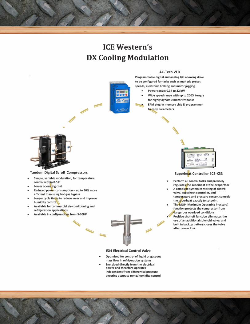
ICE Western’s DX Cooling Modulation
AC-Tech VFD Programmable digital and analog I/O allowing drive to be configured for tasks such as multiple preset speeds, electronic braking and motor jogging
• Power range: 0.37 to 22 kW
• Wide speed range with up to 200% torquefor highly dynamic motor response
• EPM plug-in memory chip & programmerto copy parameters
Superheat Controller EC3-X33
• Perform all control tasks and preciselyregulates the superheat at the evaporator
• A complete system consisting of control valve, superheat controller, and temperature and pressure sensor, controlsthe superheat exactly to setpoint
• The MOP (Maximum Operating Pressure)function protects the compressor fromdangerous overload conditions
• Positive shut-off function eliminates theuse of an additional solenoid valve, and built in backup battery closes the valve after power loss.
EX4 Electrical Control Valve • Optimized for control of liquid or gaseous
mass flow in refrigeration systems • Energized directly from the electrical
power and therefore operates independent from differential pressure ensuring accurate temp/humidity control
Tandem Digital Scro ll Compressors• Simple, variable modulation, for temperature
control within 0.5 F • Lower operating cost• Reduced power consumption – up to 30% more
efficient than using hot-gas bypass• Longer cycle times to reduce wear and improve
humidity control• Available for commercial air-conditioning and
refrigeration applications• Available in configurations from 3-30HP
39

Custom Wiring Options
•
• BMS integration of all major controlmanufacturers
Incorporated JIC Wiring
o L.O.N. Protocol/Distech
o BAC-NET Protocol/Distech DTC Control
o
o Allen Bradley PLC
Siemens PLC
36

PERFORMANCE SPECIFICATIONS
9754 54 ST SE
Calgary, AB—T2C 5J6
Phone: 403-252-5577
Fax: 403-252-5556
www.icewestern.com
TYPICAL HTDM 91+ COMPONENTS
For more information, please visit our website: www.icewestern.com
364
Reliability at its finest.