HPS/RFL™ GARD Pro™ System Instruction Manual · The information in this manual is proprietary...
256
RF-MCDGARDPRO Hubbell Power Systems, Inc. – RFL™ Products March 30, 2018 (c)2018 Hubbell Incorporated 1 HPS/RFL™ GARD Pro™ System Instruction Manual This entire document is the property of Hubbell Power Systems, Inc. (HPS) and may not be reproduced, transmitted, published or stored in an electronic retrieval system, in whole or in part, by any means – electronic or otherwise. For permission, contact: [email protected] Hubbell Power Systems, Inc. – RFL™ Products 353 Powerville Road ● Boonton Twp., NJ 07005-9151 USA Tel: 973.334.3100 ● Fax: 973.334.3863 Email: [email protected] ● www.rflelect.com Publication Number RF-MCDGARDPRO Version 004, Printed in U.S.A. March 30, 2018
Transcript of HPS/RFL™ GARD Pro™ System Instruction Manual · The information in this manual is proprietary...

RF-MCDGARDPRO Hubbell Power Systems, Inc. – RFL™ Products March 30, 2018 (c)2018 Hubbell Incorporated
1
HPS/RFL™ GARD Pro™ System Instruction Manual
This entire document is the property of Hubbell Power Systems, Inc. (HPS) and may not be
reproduced, transmitted, published or stored in an electronic retrieval system, in whole or in part, by any means – electronic or otherwise. For permission, contact: [email protected]
Hubbell Power Systems, Inc. – RFL™ Products
353 Powerville Road Boonton Twp., NJ 07005-9151 USA Tel: 973.334.3100 Fax: 973.334.3863
Email: [email protected] www.rflelect.com
Publication Number RF-MCDGARDPRO Version 004, Printed in U.S.A.
March 30, 2018

RF-MCDGARDPRO Hubbell Power Systems, Inc. – RFL™ Products March 30, 2018 (c)2018 Hubbell Incorporated
2
NOTICE
The information in this manual is proprietary and confidential to Hubbell® Power Systems, Inc. (HPS) – RFL
Products. Any reproduction or distribution of this manual, in whole or part, is expressly prohibited, unless written
permission is given by Hubbell Power Systems, Inc. – RFL Products.
This manual has been compiled and checked for accuracy; however, HPS makes no representation or warranty as
to the accuracy or completeness of the information in this manual. The information in this manual does not
constitute a warranty of performance. HPS/RFL brand products reserves the right to revise this manual and make
changes to its contents from time to time. We assume no liability for losses incurred as a result of out-of-date or
incorrect information contained in this manual.
HPS shall not have any liability resulting from the use of the information in this manual. This manual does not
purport to cover all details or variations in equipment, nor provide for every possible contingency to be met in
connection with installation, operation, or maintenance of this specific product. Should further information be
desired or should particular problems arise which are not covered sufficiently for the purchaser's purposes, the
matter should be referred to your HPS/RFL product representative or HPS/RFL Customer Service Department at
[email protected], or by visiting the website at www.rflelect.com/Support.
NOTES
It is recommended that this product be opened immediately after receiving and inspected for proper operation and
signs of impact damage.
For information regarding product warranty and repairs, please visit the HPS/RFL website at
www.rflelect.com/Support or e-mail the HPS/RFL Customer Service Department at

RF-MCDGARDPRO Hubbell Power Systems, Inc. – RFL™ Products March 30, 2018 (c)2018 Hubbell Incorporated
3
Table of Contents
Safety Instructions............................................................................................................... 1-1 Section 1.
1.1 Warnings and Safety Summary...................................................................................................... 1-1 1.2 External Labels, Warning and Cautions ......................................................................................... 1-4
System Description ............................................................................................................. 2-1 Section 2.
2.1 Key Features for the HPS/RFL™ GARD Pro™ System ................................................................ 2-1 2.2 Supplied Drawings ......................................................................................................................... 2-2 2.3 The HPS/RFL GARD Pro System Modules with Available Options ............................................... 2-2 2.4 The HPS/RFL GARD Pro System Slot Location and Module Description ..................................... 2-3 2.5 Front Panel Indicators/Connections ............................................................................................... 2-9 2.6 Graphical User Interface (GUI)..................................................................................................... 2-10 2.7 Controller Redundancy ................................................................................................................. 2-11 2.8 TSD (Touch Screen Display)........................................................................................................ 2-15
Installation ............................................................................................................................ 3-1 Section 3.
3.1 Introduction ..................................................................................................................................... 3-1 3.2 Unpacking....................................................................................................................................... 3-1 3.3 Mounting ......................................................................................................................................... 3-2 3.4 Ventilation ....................................................................................................................................... 3-4 3.5 System Module I/O Connections .................................................................................................... 3-4 3.6 Rear I/O, Alarm Relay and Input Power Connections .................................................................... 3-9 3.7 System timing ............................................................................................................................... 3-13 3.8 Current Limiter Option .................................................................................................................. 3-19 3.9 The HPS/RFL GARD Pro System Boot-Up Sequence ................................................................ 3-20
System Configuration.......................................................................................................... 4-1 Section 4.
4.1 Connecting a Laptop and Setting IP Addresses ............................................................................ 4-1 4.2 Configuring a PC Using DHCP and Static IP ................................................................................. 4-2 4.3 First Time Login to the HPS/RFL GARD Pro System Web Server ................................................ 4-5 4.4 File Operations ............................................................................................................................. 4-11 4.5 Web/SCP Server .......................................................................................................................... 4-15 4.6 Inventory and Software Information ............................................................................................. 4-19 4.7 Dynamic Menu Feature ................................................................................................................ 4-20 4.8 Changing Settings – General Information .................................................................................... 4-21 4.9 Input/Output Module ..................................................................................................................... 4-21 4.10 Front Panel LED Status and Configuration ................................................................................ 4-36 4.11 System Alarms Status and Configuration .................................................................................. 4-38 4.12 SOE Status and Configuration ................................................................................................... 4-41 4.13 Logic Configuration .................................................................................................................... 4-47 4.14 System Settings ......................................................................................................................... 4-50 4.15 Advanced Settings ..................................................................................................................... 4-52 4.16 DNP3 .......................................................................................................................................... 4-59 4.17 SNMP ......................................................................................................................................... 4-78
Power Line Carrier ............................................................................................................... 5-1 Section 5.
5.1 Power Line Carrier Function........................................................................................................... 5-1 5.2 Making Connections to the Rear Analog PLC Module ................................................................... 5-7

RF-MCDGARDPRO Hubbell Power Systems, Inc. – RFL™ Products March 30, 2018 (c)2018 Hubbell Incorporated
4
5.3 Carrier Level Indicator (CLI) Front Panel Meter ............................................................................. 5-9 5.4 PLC Module User Interface ............................................................................................................ 5-9 5.5 Power Line Carrier Commissioning .............................................................................................. 5-35 5.6 Configuring 50 and 100W applications with Optional 9508 RF Chassis ...................................... 5-49 5.7 Optional Switched Battery Power Supply ..................................................................................... 5-76 5.8 Installations with Two or More PLC Modules ............................................................................... 5-78
Troubleshooting ................................................................................................................... 6-1 Section 6.
6.1 Introduction ..................................................................................................................................... 6-1 6.2 Connectivity Issues ........................................................................................................................ 6-1 6.3 Module Level Alarms ...................................................................................................................... 6-3
Software Upgrade Utility ..................................................................................................... 7-1 Section 7.
7.1 System Firmware Upgrade Overview ............................................................................................ 7-1 7.2 The HPS/RFL GARD Pro system Upgrade Tool Installation ......................................................... 7-2 7.3 The HPS/RFL GARD Pro system Firmware Upgrade Procedure .................................................. 7-5
Technical Data/Specifications ............................................................................................ 8-1 Section 8.
8.1 System Specifications .................................................................................................................... 8-1 8.2 Optional Modules ........................................................................................................................... 8-4 8.3 DNP3 Device Profile Document ..................................................................................................... 8-6 8.4 Disposal .......................................................................................................................................... 8-8
Index ...................................................................................................................................... 9-1 Section 9.
9.1 Index ............................................................................................................................................... 9-1
Application Notes ............................................................................................................ 10-5 Section 10.

RF-MCDGARDPRO Hubbell Power Systems, Inc. – RFL™ Products March 30, 2018 (c)2018 Hubbell Incorporated
5
List of figures Figure 1-1. Location of Protective Earth Stud .......................................................................... 1-1 Figure 1-2. External Labels, Warnings and Cautions ............................................................... 1-4
Figure 2-1. The HPS/RFL GARD Pro System ......................................................................... 2-1 Figure 2-2. Supplied Drawings ................................................................................................. 2-2 Figure 2-3. Module Placement in the HPS/RFL GARD Pro System (3U) ............................... 2-3 Figure 2-4. Module Placement in the HPS/RFL GARD Pro System (6U) ............................... 2-4 Figure 2-5. Programmable LEDs .............................................................................................. 2-6
Figure 2-6. Base Input/Output Unit showing Plug-On Boards ................................................. 2-7 Figure 2-7. GPS Antenna .......................................................................................................... 2-8 Figure 2-8. HPS/RFL GARD Pro System Front Panel, Indicators/Connections ...................... 2-9 Figure 2-9. Graphical User Interface ...................................................................................... 2-10 Figure 2-10. Chassis Configuration Status web page for 6U Chassis with Redundancy ....... 2-14
Figure 2-11. Chassis Configuration Status web page for 6U Chassis with Unhealthy Inactive
Controller ................................................................................................................................. 2-14
Figure 2-12. Touch Screen Display in 3U Chassis. ................................................................ 2-15 Figure 2-13. Touch Screen Orientation .................................................................................. 2-16
Figure 2-14. Touch Screen Initialization. ............................................................................... 2-17 Figure 2-15. System Information ............................................................................................ 2-18
Figure 2-16. Events Log (SOE’s) ........................................................................................... 2-18 Figure 2-17. Push Button Menu .............................................................................................. 2-19 Figure 2-18. Test Menu........................................................................................................... 2-19
Figure 2-19. Inventory Menu .................................................................................................. 2-20 Figure 3-1. Mounting dimensions for the HPS/RFL GARD Pro system chassis ..................... 3-3
Figure 3-2. System Module I/O Connections ........................................................................... 3-5
Figure 3-3. RS-485 DNP3 connection ...................................................................................... 3-7
Figure 3-4. Network connections .............................................................................................. 3-8 Figure 3-5. Rear I/O Terminal Block Connections ................................................................... 3-9
Figure 3-6. Relay Connections/Power Supply I/O ................................................................. 3-10 Figure 3-7. Chassis Grounding Location ................................................................................ 3-11 Figure 3-8. HPS/RFL GARD Pro System – 3U Chassis, System I/O Board Jumper Locations
.................................................................................................................................................. 3-13 Figure 3-9. IRIG-B with GPS ................................................................................................. 3-15
Figure 3-10. RS-232 Pin-Outs ................................................................................................ 3-16 Figure 3-11. Removing System I/O Board (3U) ..................................................................... 3-16 Figure 3-12. Jumper Location for IRIG-B through Rear RS-232 Connector (3U) ................ 3-17 Figure 3-13. Removing System I/O Board (6U) ..................................................................... 3-17
Figure 3-14. Jumper Location for IRIG-B through Rear RS-232 Connector (6U) ................ 3-18 Figure 3-15. Current Limiter Terminal Block Connection ..................................................... 3-19 Figure 3-16. Location of LEDs on Controller Board .............................................................. 3-20
Figure 4-1. Front Ethernet Port ................................................................................................. 4-1 Figure 4-2. Internet Access Icon ............................................................................................... 4-2 Figure 4-3. Local Area Connection .......................................................................................... 4-2 Figure 4-4. Properties................................................................................................................ 4-3 Figure 4-5. Internet Protocol Version ....................................................................................... 4-3 Figure 4-6. Obtain an IP Address Automatically...................................................................... 4-4 Figure 4-7. Use the Following IP Address................................................................................ 4-4 Figure 4-8. First Time Login .................................................................................................... 4-5

RF-MCDGARDPRO Hubbell Power Systems, Inc. – RFL™ Products March 30, 2018 (c)2018 Hubbell Incorporated
6
Figure 4-9. HPS/RFL GARD Pro System Dashboard .............................................................. 4-6
Figure 4-10. Access Levels ....................................................................................................... 4-8 Figure 4-11. Access Control ..................................................................................................... 4-9 Figure 4-12. Access Log ......................................................................................................... 4-10
Figure 4-13. Send File to HPS/RFL GARD Pro System ........................................................ 4-11 Figure 4-14. Save File to PC ................................................................................................... 4-13 Figure 4-15. Web/SCP Server................................................................................................. 4-15 Figure 4-16. Inventory and Version Control........................................................................... 4-19 Figure 4-17. Dynamic Menu Feature ...................................................................................... 4-20
Figure 4-18. Settings, General Information ............................................................................ 4-21 Figure 4-19. Removing Input/Output Module ........................................................................ 4-22 Figure 4-20. Setting Jumpers on the Input Unit ...................................................................... 4-23 Figure 4-21. Setting Switches on the Relay Output Unit........................................................ 4-24
Figure 4-22. I/O Status ............................................................................................................ 4-25 Figure 4-23. Configuring Inputs ............................................................................................. 4-26
Figure 4-24. Input Mapping .................................................................................................... 4-27 Figure 4-25. Inputs Advanced Configuration ......................................................................... 4-28
Figure 4-26. Input Test ........................................................................................................... 4-29 Figure 4-27. Output Configuration ......................................................................................... 4-31 Figure 4-28. Output Mapping ................................................................................................. 4-32
Figure 4-29. Output Advanced Configuration ........................................................................ 4-33 Figure 4-30. Output Test ......................................................................................................... 4-34
Figure 4-31. LED Status ......................................................................................................... 4-36 Figure 4-32. LED Configuration............................................................................................. 4-37 Figure 4-33. Alarm Status ....................................................................................................... 4-38
Figure 4-34. Alarm Configuration .......................................................................................... 4-40
Figure 4-35. Retrieving SOE Records .................................................................................... 4-41 Figure 4-36. SOE Triggers ...................................................................................................... 4-43 Figure 4-37. SOE Record Details (Logic Bits) ....................................................................... 4-44
Figure 4-38. SOE Record Details (Logic Table) .................................................................... 4-45 Figure 4-39. SOE Counters ..................................................................................................... 4-46
Figure 4-40. SOE Configuration ............................................................................................. 4-47 Figure 4-41. Logic Options ..................................................................................................... 4-48
Figure 4-42. Logic Configuration, Timers .............................................................................. 4-49 Figure 4-43. System Configuration, Ethernet Labels ............................................................. 4-50 Figure 4-44. System Configuration, Clock ............................................................................. 4-51 Figure 4-45. Advanced Settings, Logic Bits ........................................................................... 4-52 Figure 4-46. Advanced Settings, HMI Bits ............................................................................ 4-53
Figure 4-47. TSD Wake-Up Settings ...................................................................................... 4-55 Figure 4-48. TSD Push Button Interface Configuration. ........................................................ 4-56
Figure 4-49. TSD Push Button Interface. ............................................................................... 4-57 Figure 4-50. TSD Blank Button .............................................................................................. 4-58 Figure 5-1. Minimum Channel Spacing (FSK)......................................................................... 5-3 Figure 5-2. As Supplied Drawing ............................................................................................. 5-7 Figure 5-3. HPS/RFL GARD Pro system PLC Analog Module .............................................. 5-8 Figure 5-4. CLI Meter, Front Panel Mounting on a 3U Chassis ............................................... 5-9 Figure 5-5. FSK Status ............................................................................................................ 5-10 Figure 5-6. FSK Configuration ............................................................................................... 5-12

RF-MCDGARDPRO Hubbell Power Systems, Inc. – RFL™ Products March 30, 2018 (c)2018 Hubbell Incorporated
7
Figure 5-7. FSK Configuration, Advanced ............................................................................. 5-14
Figure 5-8. Function Buttons .................................................................................................. 5-15 Figure 5-9. FSK Test............................................................................................................... 5-19 Figure 5-10. On/Off Status ..................................................................................................... 5-20
Figure 5-11. On/Off Configuration ......................................................................................... 5-22 Figure 5-12. On/Off Configuration, Advanced....................................................................... 5-24 Figure 5-13. On/Off Configuration, Checkback ..................................................................... 5-27 Figure 5-14. On/Off Configuration, Hard Carrier .................................................................. 5-30 Figure 5-15. On/Off Test ........................................................................................................ 5-33
Figure 5-16. Receiver Operating Range and Dynamic Range ................................................ 5-34 Figure 5-17. PLC Calibration ................................................................................................. 5-36 Figure 5-18. PLC Rear Module Adjustments ......................................................................... 5-38 Figure 5-19. PLC Verifying Jumpers J12 through J15 ........................................................... 5-40
Figure 5-20. PLC Verifying Jumpers J16 through J20 ........................................................... 5-41 Figure 5-21. PLC Verifying Jumpers J21 through J25 ........................................................... 5-42
Figure 5-22. PLC Jumper Settings, Transmit Carrier Frequency Range ................................ 5-43 Figure 5-23. PLC Analog Module, Carrier Level Indicator Modes - Jumpers ....................... 5-46
Figure 5-24. Location of Potentiometers on Digital PLC Module ......................................... 5-47 Figure 5-25. J6 Pin Numbers .................................................................................................. 5-48 Figure 5-26. 9508 RF Chassis Mounted on the HPS/RFL GARD Pro System ...................... 5-49
Figure 5-27. Front View of the 9508 RF Chassis Showing Module Locations in 50W System
.................................................................................................................................................. 5-51
Figure 5-28. 9508 RF Chassis Block Diagram ....................................................................... 5-52 Figure 5-29. 9508 RF Chassis Power Amplifier ..................................................................... 5-53 Figure 5-30. Additional 50W Module in 100W Systems ....................................................... 5-54
Figure 5-31. Location of 50W Power Amplifier Module ....................................................... 5-54
Figure 5-32. 50W Power Amp Circuit Board ......................................................................... 5-55 Figure 5-33. Power Amplifier, Power Supply ........................................................................ 5-57 Figure 5-34. Power Amplifier, Power Supply, Block Diagram .............................................. 5-58
Figure 5-35. TX Filter, Top View ........................................................................................... 5-58 Figure 5-36. Location of Jumpers on the TX Filter, PC Board 107828-2 .............................. 5-60
Figure 5-37. Location of Jumpers on the TX Filter, PC Board 107828-1 .............................. 5-62 Figure 5-38. Balance Board .................................................................................................... 5-63
Figure 5-39. Location of Jumpers on the Balance Board ....................................................... 5-64 Figure 5-40. Line Board .......................................................................................................... 5-65 Figure 5-41. RFL9508 Line Board, Block Diagram ............................................................... 5-65 Figure 5-42. Location of Jumpers on the Line board .............................................................. 5-67 Figure 5-43. Location of Jumpers on the RX Filter board ...................................................... 5-68
Figure 5-44. Location of Jumpers on the RX Filter board, Showing Jumper Groupings ....... 5-69 Figure 5-45. 9508 Attenuator Board ....................................................................................... 5-70
Figure 5-46. 9508 Mother Board, Rear View ......................................................................... 5-71 Figure 5-47. Rear Panel Wiring of a typical HPS/RFL GARD Pro system PLC with a 50W
9508 RF Chassis. ..................................................................................................................... 5-74 Figure 5-48. Rear Panel Wiring of a typical HPS/RFL GARD Pro system PLC with a 100W
9508 RF Chassis. ..................................................................................................................... 5-75 Figure 5-49. Optional Power Supply I/O Module, Single On/Off Switch.............................. 5-76 Figure 5-50. Switched Battery Output, Functional Diagram .................................................. 5-77 Figure 5-51. Making Connections to a Second PLC Module ................................................. 5-78

RF-MCDGARDPRO Hubbell Power Systems, Inc. – RFL™ Products March 30, 2018 (c)2018 Hubbell Incorporated
8
Figure 5-52. Setting Jumpers on Second PLC Analog Module .............................................. 5-79
Figure 6-1. Connectivity Flow Chart ........................................................................................ 6-2 Figure 6-2. PLC Digital Board.................................................................................................. 6-5 Figure 6-3. PLC Analog Module Top View ............................................................................. 6-8
Figure 6-4. PLC Analog Module Rear Panel View .................................................................. 6-9 Figure 6-5. PLC Power Amp Section ....................................................................................... 6-9
RF-MCDGARDPRO Hubbell Power Systems, Inc. – RFL™ Products March 30, 2018 (c)2018 Hubbell Incorporated
9
List of Tables Table 2-1 HPS/RFL GARD Pro System Module with Available Options ................................ 2-2 Table 2-2. Web Page, Controller Card, Status Color Codes ................................................... 2-13
Table 2-3 Button States and Actions ....................................................................................... 2-16 Table 3-1. Jumpers Required on System I/O Board when GPS Module is NOT INSTALLED
.................................................................................................................................................. 3-14 Table 3-2. System I/O jumper Settings with IRIG-B and GPS .............................................. 3-15 Table 4-1 Alarm States .............................................................................................................. 4-7
Table 4-2 Setting Access Levels ................................................................................................ 4-7 Table 4-3 Security Levels ........................................................................................................ 4-16 Table 4-4 LED Priorites ........................................................................................................... 4-37 Table 4-5. TSD Push Button Interface fields .......................................................................... 4-57 Table 4-6. HPS/RFL GARD Pro system list of DNP3 data points ......................................... 4-60
Table 4-7. General Configuration fields ................................................................................. 4-64 Table 4-8. DNP Type Configuration Field Descriptions ........................................................ 4-66
Table 4-9. DNP Status fields .................................................................................................. 4-72 Table 4-10. Field descriptions for DNP status ........................................................................ 4-73
Table 4-11. SNMP Configuration webpage fields .................................................................. 4-81 Table 4-12. SNMP trap MIB contents .................................................................................... 4-82
Table 5-1 2F Trip Transport Delay and Channel Spacing ......................................................... 5-2 Table 5-2 3F Trip Transport Delay and Channel Spacing ......................................................... 5-2 Table 5-3 On/Off Block Transport Delay and Channel Spacing ............................................... 5-5
Table 5-4. Compatibility Issues for PLC Module Software ..................................................... 5-5 Table 5-5 TB1 Terminal Assignments ....................................................................................... 5-8
Table 5-6 Transmitter State ..................................................................................................... 5-10
Table 5-7 Reciever State .......................................................................................................... 5-11
Table 5-8 Recommended FSK Settings ................................................................................... 5-16 Table 5-9 Recommended On/Off Settings ............................................................................... 5-25
Table 5-10 Recommended Checkback Settings, 2-Terminal Line Testing ............................. 5-28 Table 5-11 Recommended Checkback Settings, 3-Terminal Line Testing ............................. 5-29 Table 5-12 Recommended Hard Carrier Settings, 2-Terminal Line Testing ........................... 5-31
Table 5-13 Recommended Hard Carrier Settings, 3-Terminal Line Testing ........................... 5-32 Table 5-14. PLC Calibration ................................................................................................... 5-37
Table 5-15. PLC Analog Module Assembly Part Numbers (500935-X, New Board) ........... 5-44 Table 5-16. TX Filter Jumper settings (500935-X, New Board) ............................................ 5-44 Table 5-17. PLC Analog Module Assembly Part Numbers (500930-X, Old Board) ............. 5-45 Table 5-18. TX Filter Jumper settings (500930-X, Old Board) ............................................. 5-45
Table 5-19. Carrier Level Indicator loads ............................................................................... 5-47 Table 5-20. Modules Included in the 9508 RF Chassis .......................................................... 5-50 Table 5-21 Function of the Jumpers, Connectors and Potentiometers on the Power Amp Circuit
Board ........................................................................................................................................ 5-55 Table 5-22 Function of the DIP Switches SW1 and SW2 on the Power Amp Board ............. 5-56 Table 5-23 Power Amp, Power Supplies ................................................................................. 5-57 Table 5-24 TX Filter Setup Jumpers ........................................................................................ 5-61 Table 5-25 Setting Jumpers on the Balance Board .................................................................. 5-64 Table 5-26 Line Board, Setup Jumpers and Switch Settings ................................................... 5-67 Table 5-27 Motherboard Rear Panel Connector Assignments ................................................ 5-71 Table 5-28 Motherboard, TB1 Terminal Assignments ............................................................ 5-72

RF-MCDGARDPRO Hubbell Power Systems, Inc. – RFL™ Products March 30, 2018 (c)2018 Hubbell Incorporated
10
Table 5-29 TB1 Connections on Second PLC Module ........................................................... 5-79
Table 6-1 PLC Digital Module, Module Level Alarms ............................................................. 6-3 Table 6-2 PLC Common PLC Troubleshooting Issues ............................................................. 6-4 Table 6-3 Settings for the PLC Digital Board ........................................................................... 6-6
Table 6-4 Settings for the PLC Analog Module ...................................................................... 6-10 Table 8-1 The HPS/RFL GARD Pro System Power Supply Specifications ............................. 8-3

RF-MCDGARDPRO Hubbell Power Systems, Inc. – RFL™ Products March 30, 2018 (c)2018 Hubbell Incorporated
11
List of Effective Pages
When revisions are made to the HPS/RFL™ GARD Pro™ System Instruction Manual, the
entire section where revisions were made is replaced. For this addition of the Instruction
Manual dated February 16, 2018 the sections are dated as follows.
Section Date
Front Section, TOC etc. January 13, 2017
Section 1. January 13, 2017
Section 2. March 1, 2018
Section 3. March 1, 2018
Section 4. March 1, 2018
Section 5. March 1, 2018
Section 6. December 9, 2016
Section 7. March 1, 2018
Section 8. January 1, 2016
Section 9. March 1, 2018
Section 10. December 1, 2015
Trademark information:
RFL™ GARD Pro™ System is a trademark of Hubbell Power Systems, Inc.
“Windows” is a registered trademark of Microsoft Corporation.
“Ethernet” is a trademark of Xerox Corporation.
The trademark information listed above is, to the best of our knowledge, accurate and complete
Revision Record
Rev. Date on Manual
Description of Changes Actual Date Released
12/1/15 Initial Release under ECO 8000-572 12/1/2015
03/1/16 Added Emulator and Troubleshooting Sections 03/9/2016
12/16/16 Added TSD section, Upgrade tool and New controller with Redundancy
1/13/2017
04/05/17 Revised Hubbell and RFL Logos and Header/Footer contents.
04/10/2017
03/13/18 Updated DNP3 and SNMP Sections. Updated screen shots for the updated interface. Updated for System Firmware 2.2.0
03/30/2018

RF-MCDGARDPRO Hubbell Power Systems, Inc. – RFL™ Products March 30, 2018 (c)2018 Hubbell Incorporated
12
Ordering Information, Decoding the Part Number Serial and part number information is located on the right mounting bracket (ear) of the
HPS/RFL™ GARD Pro™ system unit as shown below. The smart number and drawing
numbers are located on the other mounting bracket along with other customer information.
SO 170523
PO 02345210000
PN GARD3U476
SN 07420072
Sales order numberPurchase order number
Part numberSerial number
RH
LH
GARD5D0E100AA31
CD64144
00084_001_A
00084_001_A_CXX
Smart number see the
following page for
configurator Drawing number
Customer number
Part of software
number
Software revision
Configuration number, for
example different units
could have different
frequency settings

RF-MCDGARDPRO Hubbell Power Systems, Inc. – RFL™ Products March 30, 2018 (c)2018 Hubbell Incorporated
13
The following pages list the possible ordering options:
Product Smart Number >> GPRO 3U
Front Panel Touch Screen Display
None 0
Yes TSD
Yes with Stylus Tether TSDT
Front Panel Test Switch
None 0
Standard TD
Primary Power Supply Voltage Input
24 VDC 24
48 VDC 48
125 VDC or 120 VAC 125
250 VDC 250
Redundant Power Supply Voltage Input
None 0
24 VDC 24
48 VDC 48
125 VDC or 120 VAC 125
250 VDC 250
Power Supply Interface
With Multiprotocol (RS-449, V.35, X.21) Digital I/O MP
With Double Pole Switched Battery Output DP
Front System Display Module
Without Digital Teleprotection Functionality No
Redundant Controller
No 0
System I/O Ethernet Port Type
Electrical E
Fiber Optic F
GPS for System Clock Synchronization
Yes G
No 0
Front Functional Modules (Select Eight with 6U and Two with 3U)
Power Line Carrier FSK or On/Off (50 Ohms) w/CLI Meter
Power Line Carrier FSK or On/Off (75 Ohms) w/CLI Meter
TX Only Power Line Carrier FSK (50 Ohms)
TX Only Power Line Carrier FSK (75 Ohms)
RX Only Power Line Carrier FSK (50/75 Ohms) w/CLI Meter
Power Line Carrier FSK or On/Off - No Hybrid (50 Ohms) w/CLI Meter
Power Line Carrier for External Power Amp
Empty
Rear I/O Terminal Block Type
Screw S
Commpression C
Rear I/O Modules (Select Ten with 6U and Four with 3U )
Occupied Slot Based On Front Module Selection
Empty
Discrete I/O Units
6 Inputs
6 Solid State Outputs
6 Relay Outputs
12 Inputs
12 Solid State Outputs
12 Relay Outputs
6 Solid State Outputs and 6 Relay Outputs
6 Solid State Outputs and 6 Inputs
6 Relay Outputs and 6 Inputs
Current Limiting Output
None 0
48 Vdc CL48
125 Vdc CL125
Effective: 3/16/17
SI
RI
RFL® GARD Pro™ 3U - Ordering Information
Consumes two rear slots in corresponding slot number
Consumes two rear slots in corresponding slot number
Consumes two rear slots in corresponding slot number
Consumes two rear slots in corresponding slot number
Consumes two rear slots in corresponding slot number
Consumes two rear slots in corresponding slot number
Consumes two rear slots in corresponding slot number
Rear Slots 1 through 4
/----------------------------Select 4 I/O----------------------------\
Fro
nt S
lot 4
RR
SR
Fro
nt S
lot 3
Re
ar S
lot 1
Re
ar S
lot 2
Re
ar S
lot 3
Re
ar S
lot 4
SS
IE
SE
RE
II
/-Select 2 Functions-\
Front Slots 4 - 3
X
0
P5 & 0 (uses two slots)
P7 & 0 (uses two slots)
T5 & 0 (uses two slots)
T7 & 0 (uses two slots)
PR & 0 (uses two slots)
PN & 0 (uses two slots)
PX & 0 (uses two slots)
0

RF-MCDGARDPRO Hubbell Power Systems, Inc. – RFL™ Products March 30, 2018 (c)2018 Hubbell Incorporated
14
Product Smart Number >> GPRO 6U
Front Panel Touch Screen Display
None 0
Yes TSD
Yes with Stylus Tether TSDT
Front Panel Test Switch
None 0
Standard TD
Primary Power Supply Voltage Input
24 VDC 24
48 VDC 48
125 VDC or 120 VAC 125
250 VDC 250
Dual PS 24 VDC (for multiple PLC applications) D24
Dual PS 48 VDC (for multiple PLC applications) D48
Dual PS 125 VDC or 120 VAC (for multiple PLC applications) D125
Dual PS 250 VDC (for multiple PLC applications) D250
Redundant Power Supply Voltage Input
None 0
24 VDC 24
48 VDC 48
125 VDC or 120 VAC 125
250 VDC 250
Dual PS 24 VDC (for multiple PLC applications) D24
Dual PS 48 VDC (for multiple PLC applications) D48
Dual PS 125 VDC or 120 VAC (for multiple PLC applications) D125
Dual PS 250 VDC (for multiple PLC applications) D250
Power Supply Interface
With Multiprotocol (RS-449, V.35, X.21) Digital I/O MP
Front System Display Module
Without Digital Teleprotection Functionality No
Redundant Controller
Yes R
No 0
System I/O Ethernet Port Type
Electrical E
Fiber Optic F
GPS for System Clock Synchronization
Yes G
No 0
Front Functional Modules (Select Eight with 6U and Two with 3U)
Power Line Carrier FSK or On/Off (50 Ohms) w/CLI Meter
Power Line Carrier FSK or On/Off (75 Ohms) w/CLI Meter
TX Only Power Line Carrier FSK (50 Ohms)
TX Only Power Line Carrier FSK (75 Ohms)
RX Only Power Line Carrier FSK (50/75 Ohms) w/CLI Meter
Power Line Carrier FSK or On/Off - No Hybrid (50 Ohms) w/CLI Meter
Power Line Carrier for External Power Amp
Empty
Rear I/O Terminal Block Type
Screw S
Commpression C
Rear I/O Modules (Select Ten with 6U and Four with 3U )
Occupied Slot Based On Front Module Selection
Empty
Discrete I/O Units
6 Inputs
6 Solid State Outputs
6 Relay Outputs
12 Inputs
12 Solid State Outputs
12 Relay Outputs
6 Solid State Outputs and 6 Relay Outputs
6 Solid State Outputs and 6 Inputs
6 Relay Outputs and 6 Inputs
Current Limiting Output
None 0
48 Vdc CL48
125 Vdc CL125
Effective: 3/16/17
Consumes two rear slots in corresponding slot number
Fro
nt S
lot 4
Re
ar S
lot 7
Re
ar S
lot 8
Re
ar S
lot 9
Re
ar S
lot 1
0
Consumes two rear slots in corresponding slot number
Re
ar S
lot 2
Re
ar S
lot 3
Re
ar S
lot 4
Re
ar S
lot 5
Re
ar S
lot 6
Consumes two rear slots in corresponding slot number
SI
RI
SR
SS
RR
II
RE
SE
IE
X
0
Consumes two rear slots in corresponding slot number
Consumes two rear slots in corresponding slot number
0
PR & 0 (uses two slots)
PN & 0 (uses two slots)
PX & 0 (uses two slots)
T7 & 0 (uses two slots)
RFL® GARD Pro™ 6U - Ordering Information
P5 & 0 (uses two slots)
Fro
nt S
lot 3
Fro
nt S
lot 2
Fro
nt S
lot 1
Re
ar S
lot 1
Rear Slots 1 through 10
/-------------------------------Select 10 I/O------------------------------\
Front Slots 8 through 1
Consumes two rear slots in corresponding slot number
Consumes two rear slots in corresponding slot number
/--------------------Select 8 Functions------------------\
Fro
nt S
lot 8
Fro
nt S
lot 7
P7 & 0 (uses two slots)
T5 & 0 (uses two slots)
Fro
nt S
lot 6
Fro
nt S
lot 5

Safety Instructions
RF-MCDGARDPRO Hubbell Power Systems, Inc. – RFL™ Products March 30, 2018 (c)2018 Hubbell Incorporated
1-1
Safety Instructions Section 1.
1.1 Warnings and Safety Summary
The equipment described in this manual contains high voltage.
Exercise due care during operation and servicing. Read the safety
summary below.!
1.1.1 Safety Summary
The following safety precautions must be observed at all times during operation, service, and
repair of this equipment. Failure to comply with these precautions, or with specific warnings
elsewhere in this manual, violates safety standards of design, manufacture, and intended use of
this product. HPS/RFL assumes no liability for failure to comply with these requirements.
Ground the Chassis
The chassis must be grounded to reduce shock hazard and allow the equipment to perform
properly. Equipment supplied with three-wire AC power cables must be plugged into an
approved three-contact electric outlet. All other equipment is provided with a rear-panel
protective earth terminal, which must be connected to a proper electrical ground by suitable
cabling. The location of the protective earth terminal on the HPS/RFL™ GARD Pro™ system
is shown below. Refer to the wiring diagram supplied with the unit for additional information
on chassis and/or cabinet grounding.
A protective earth stud at the lower right rear of the HPS/RFL GARD Pro system chassis is the
main ground for the HPS/RFL GARD Pro system.
MAJOR MINOR
Protective Earth Stud
Figure 1-1. Location of Protective Earth Stud

Safety Instructions
RF-MCDGARDPRO Hubbell Power Systems, Inc. – RFL™ Products March 30, 2018 (c)2018 Hubbell Incorporated
1-2
Do not Operate in an Explosive Atmosphere or in Wet or Damp Areas!
Do not operate the product in the presence of flammable gases or fumes, or in any area that is
wet or damp. Operating any electrical equipment under these conditions can result in a definite
safety hazard.
Keep Away from Live Circuits
Operating personnel should never remove covers. Component replacement and internal
adjustments must be done by qualified service personnel. Before attempting any work inside
the product, disconnect it from the power source and discharge the circuit by temporarily
grounding it. This will remove any dangerous voltages that may still be present after power is
removed.
Unrestricted operator access is only permitted to the front of the unit when hazardous voltage is
applied. It is the responsibility of the installer to restrict access to the rear terminal blocks
where hazardous voltage may exist.
Do not Substitute Parts or Modify Equipment!
Because of the danger of introducing additional hazards, do not install substitute parts or make
unauthorized modifications to the equipment. The product may be returned to HPS/RFL for
service and repair, to ensure that all safety features are maintained.
Read the Manual!
Operators should read this manual before attempting to use the equipment, to learn how to use
the equipment properly and safely. Service personnel must be properly trained and have the
proper tools and equipment before attempting to make adjustments or repairs.
Service personnel must recognize that whenever work is being done on the product, there is a
potential electrical shock hazard and appropriate protection measures must be taken. Electrical
shock can result in serious injury, because it can cause unconsciousness, cardiac arrest, and
brain damage.
Throughout this manual, warnings appear before procedures that are potentially dangerous, and
cautions appear before procedures that may result in equipment damage or service outage if not
performed properly. The instructions contained in these warnings and cautions must be
followed exactly.

Safety Instructions
RF-MCDGARDPRO Hubbell Power Systems, Inc. – RFL™ Products March 30, 2018 (c)2018 Hubbell Incorporated
1-3
1.1.2 Additional Warnings
WARNING!
On initial installation, ensure that all modules are fully seated into connectors before powering
on the unit.
WARNING!
Follow all of your company’s policies and procedures regarding the installation of AC powered
or DC powered equipment. If there is a conflict between any procedure in this manual and your
company’s safety rules, then your company’s safety rules must take priority.
WARNING!
Individual double pole disconnects must be installed between the building or station battery
supply and the HPS/RFL GARD Pro system power supply(ies). This must be done for both the
main and back-up supply.
WARNING!
The power supplies used in this equipment utilize fuses on both input lines. Therefore in AC
applications the neutral line is fused. When a fuse is blown on the neutral line the internal
circuits may be energized.
1.1.3 Additional Cautions
CAUTION
Any installation using an enclosed cabinet with a swing-out rack must be securely fastened to
the floor. This will prevent the cabinet from falling forward when the rack is moved outward.
CAUTION
This equipment contains static sensitive devices. Persons working on this equipment must
observe electro static discharge (ESD) precautions before opening the unit or working on the
rear of the chassis. As a minimum you must do the following: Use anti-static devices such as
wrist straps and floor mats.
Additional warnings and cautions appear throughout the manual, these warnings and cautions
must be followed exactly.

Safety Instructions
RF-MCDGARDPRO Hubbell Power Systems, Inc. – RFL™ Products March 30, 2018 (c)2018 Hubbell Incorporated
1-4
NOTICE
RFL products are not designed for safety critical direct control of nuclear reactors and should
not be used as such.
NOTICE
The use of ungrounded instruments such as hand held voltmeters has been shown to generate
Electro-Static Discharge. Care should be taken when using such devices on test points internal
to HPS/RFL equipment. Specifically, the use of probes manufactured under the Pomona brand
is not recommended.
1.2 External Labels, Warning and Cautions
Note the position of the power supply label so that the delivered unit’s configuration may be
verified with how it was ordered.
CAUTIONTO PREVENT ELECTRICAL SHOCK
PROPER CAUTION MUST BE EXERCISED WHEN SERVICING THIS EQUIPMENT
ALL TERMINALS ON THE REAR OF THIS UNIT MAY HAVE HIGH VOLTAGE !
This device complies with Part 15 of the FCC
rules and regulations. Operation is subject to the
following two conditions: (1) This device may not
cause harmful interference, and (2) this device
must accept any interference including
interference that may cause undesired operation.
CAUTION
!
FOR YOUR SAFETY
THE INSTALLATION, OPERATION AND
MAINTENANCE OF THIS EQUIPMENT
SHOULD BE PERFORMED BY
QUALIFIED PERSONS ONLY.
3U PLC Pro shown, position of
labels on 6U unit similar
This system left the factory configured as follows:
48/125VDC
120VAC
250VDC
220VAC
48/125VDC
120VAC
250VDC
220VAC
24VDC
24VDC
Power Supply 1
Power Supply 2
Input Modules 48VDC24VDC 125VDC 250VDC
Input Modules can be configured fo 24V, 48V, 125V
or 250V by changing jumper positions.
See the manual for further information.
Power Supply and Input Module boxes will be checked as per
factory configuration.
Figure 1-2. External Labels, Warnings and Cautions

System Description
RF-MCDGARDPRO Hubbell Power Systems, Inc. – RFL™ Products March 30, 2018 (c)2018 Hubbell Incorporated
2-1
System Description Section 2.
2.1 Key Features for the HPS/RFL™ GARD Pro™ System
Figure 2-1. The HPS/RFL GARD Pro System
World class, easy to use Graphical User Interface (GUI)
Use 6U chassis for up to 8-functions or 3U chassis for up to 2-functions
Integrated Protective Relay and Communications System
Selectable redundancy for power supply, main processor, and functional modules
Factory customized programmable logic for specific applications
Optional built-in GPS receiver

System Description
RF-MCDGARDPRO Hubbell Power Systems, Inc. – RFL™ Products March 30, 2018 (c)2018 Hubbell Incorporated
2-2
2.2 Supplied Drawings
Refer to the “as supplied” drawings furnished with your HPS/RFL GARD Pro system unit for
detailed descriptions of the connections that must be made to your system. An example
drawing is shown below.
Front view of the RFL™
GARD Pro™ System
chassis
Front view of RFL™ GARD
Pro™ System chassis with front
panel removed
Rear view of RFL™ GARD
Pro™ System chassisJumper Settings
(PLC option)Input/Output
mapping
System Jumper
Settings
Figure 2-2. Supplied Drawings
2.3 The HPS/RFL GARD Pro System Modules with Available Options
Table 2-1 HPS/RFL GARD Pro System Module with Available Options
Module Type Module Assembly Number Refer to the following Sections
Base System Module
Controller Module RF-500400-2-20 -
Display Module RF-500410-9 2.5, 4.10
Power Supply Module RF-500305, RF-500315, RF-500325
8.1.2
Power Supply I/O Module RF-500310 Series 3.6.2
System I/O Module RF-500430-1, RF-500435, RF-500435-1, RF-500420-1, RF-500425-1
3.6
I/O Base Module I/O Base Module RF-500800 Series 3.6.1, 4.9, 4.9.3
Input Output Modules
Input Module RF-500805 2.4.1, 4.9.1
Solid State Output RF-500810 2.4.1
Relay Output RF-500815 2.4.1, 4.9.3
Available Options
PLC Digital Module RF-500455-1 6.3
PLC Analog Module RF-500935 Series 2.4.1, 5.2, 5.4, 5.5.3
Current Limit Module RF-106510 Series 3.6
Touch Screen Display (TSD) RF-500480-20 2.8

System Description
RF-MCDGARDPRO Hubbell Power Systems, Inc. – RFL™ Products March 30, 2018 (c)2018 Hubbell Incorporated
2-3
2.4 The HPS/RFL GARD Pro System Slot Location and Module Description
The 3U chassis has 4-slots and the 6U chassis has 11-slots available in the front and rear of the
HPS/RFL GARD Pro system; however the base system modules have fixed locations (slots) in
both chassis as shown in the following illustrations. The illustrations show the location of the
base system modules and the slot numbering schemes in both chassis. Note that the PLC
Analog Module shown on the following pages uses two slots in the rear of the unit.
Note: The component numbering corresponds to paragraphs in section 2.4.1.
Display Module (Slot 1)
Functional Modules (Slot 3 and 4)
Single Main Controller (Slot 2) SparePower Supply No2.
Power Supply No1.
3U Midplane
4. System I/O Module
1. Main Input/Output
Module
5. Power Supply I/O Module
3. Power Line Carrier Analog Module (Option)
2. Spare
6. Extraction
Tool
1
2
3
4
1
2
3
4
Front of Unit
(Front Panel Removed)
Rear of Unit
Figure 2-3. Module Placement in the HPS/RFL GARD Pro System (3U)
Shown below is a typical HPS/RFL GARD Pro system 6U chassis arrangement. This
arrangement has two PLC Modules with associated second Power Supply and two I/O Base
Modules.

System Description
RF-MCDGARDPRO Hubbell Power Systems, Inc. – RFL™ Products March 30, 2018 (c)2018 Hubbell Incorporated
2-4
Note: The System I/O Module is different in appearance than the 3U chassis, but has the same
functions.
1234567891011
6U Midplane
Power Supply No2
Power Supply No1
Spare
Controller Module Redundant
Controller Module
Display Module
Second I/O Module
4. System I/O Module
1. Input/Output Modules
3. Power Line Carrier Analog
Modules (optional)
5. Power Supply I/O Module2. Spare Slot
2. Spare Slot
1 2 3 4 5 6 7 8 9 10 11
Front of Unit
(Front Panel Removed)
Rear of Unit
Figure 2-4. Module Placement in the HPS/RFL GARD Pro System (6U)

System Description
RF-MCDGARDPRO Hubbell Power Systems, Inc. – RFL™ Products March 30, 2018 (c)2018 Hubbell Incorporated
2-5
2.4.1 Module Descriptions
1. Display Module
The display module is required. It consists of the front panel LEDs and the Front
Ethernet Port.
The display unit handles all HMI communications tasks. The front of the board is
supplied with 20 programmable tri-colored LED’s and a TCP/IP port for PC web
browser connection.
The main user interface is a web server connected to a PC via the TCP/IP port. There is
an optional front mounted TSD (Touch Screen Display, see 2.8).

System Description
RF-MCDGARDPRO Hubbell Power Systems, Inc. – RFL™ Products March 30, 2018 (c)2018 Hubbell Incorporated
2-6
The programmable LEDs are factory configured or customized by the end user.
Note Typically not all the LED indicators are used.
POWER
NET
RESET
12
1920
Trip Key 1
Trip Key 2
Trip RX 1
Trip RX 2
Guard RX
RX Alarm
TX Fail
RPM Alarm
System Major Alarm
System Minor Alarm
Green indicates that power is
applied to the GARD
Programmable reset button
will reset the LED's as specified
RJ-45 Ethernet Port
LED's shown active
Figure 2-5. Programmable LEDs
2. Input/Output Module:
This is an I/O Base Module also known as the Discrete I/O Base Module which is the
main carrier board for the following types of I/O modules:
o Input Unit
o Solid State Output Unit
o Relay Output Unit
System Description
RF-MCDGARDPRO Hubbell Power Systems, Inc. – RFL™ Products March 30, 2018 (c)2018 Hubbell Incorporated
2-7
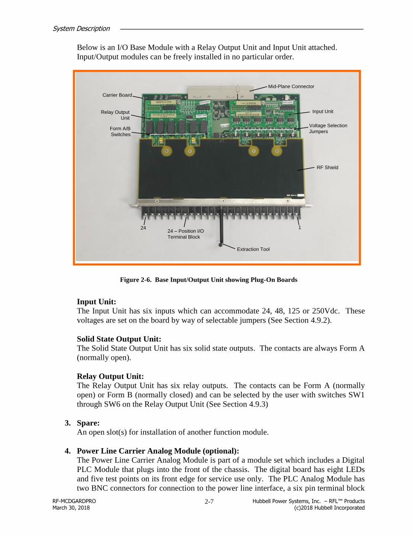
Below is an I/O Base Module with a Relay Output Unit and Input Unit attached.
Input/Output modules can be freely installed in no particular order.
Extraction Tool
RF Shield
Mid-Plane Connector
Input UnitRelay Output
Unit
Carrier Board
24 – Position I/O
Terminal Block
Voltage Selection
JumpersForm A/B
Switches
124
Figure 2-6. Base Input/Output Unit showing Plug-On Boards
Input Unit:
The Input Unit has six inputs which can accommodate 24, 48, 125 or 250Vdc. These
voltages are set on the board by way of selectable jumpers (See Section 4.9.2).
Solid State Output Unit:
The Solid State Output Unit has six solid state outputs. The contacts are always Form A
(normally open).
Relay Output Unit:
The Relay Output Unit has six relay outputs. The contacts can be Form A (normally
open) or Form B (normally closed) and can be selected by the user with switches SW1
through SW6 on the Relay Output Unit (See Section 4.9.3)
3. Spare:
An open slot(s) for installation of another function module.
4. Power Line Carrier Analog Module (optional):
The Power Line Carrier Analog Module is part of a module set which includes a Digital
PLC Module that plugs into the front of the chassis. The digital board has eight LEDs
and five test points on its front edge for service use only. The PLC Analog Module has
two BNC connectors for connection to the power line interface, a six pin terminal block

System Description
RF-MCDGARDPRO Hubbell Power Systems, Inc. – RFL™ Products March 30, 2018 (c)2018 Hubbell Incorporated
2-8
for connecting a CLI meter or second power supply. There are also fine and coarse
tuning controls and various variable resistors used to control the amplifier.
See Section 5 for a complete description of the PLC function.
5. System I/O Module:
The function of the System I/O Module is to provide the physical connection point
between the HPS/RFL GARD Pro system and the substation network. In addition to
this, the System I/O Module provides the following three timing functions:
o Optional GPS
o IRIG-B
o 1PPS (1 pulse per second timing signal)
An Optional GPS interface module (GPS time receiver) can be installed in the System
I/O Module. When it is installed, a GPS antenna must be connected to the SMA series
connector labeled “GPS” at the rear of the System I/O Module. When the GPS option is
installed, the BNC connectors labeled “IRIG-B’ and “1PPS” function as outputs and can
be used to drive equipment external to the HPS/RFL GARD Pro system. In this case the
IRIG-B output is un-modulated.
When the GPS built-in receiver is included, it resides as a piggy-back module on the
System I/O Module. The GPS receiver has to be connected to an externally mounted
antenna, provided as an accessory as shown below.
Figure 2-7. GPS Antenna
Also located on the System I/O Module is a six pin (RS-485) terminal block for use with
the DNP protocol. The six pin connector is always installed, but only used when DNP
is enabled over RS-485. The Ethernet port is used for remote management purposes.
An RS-232 port is also available for management.
6. Power Supply I/O Module:
The Powers Supply I/O Module has the following three functions:
o Connects the internal power supplies to the external power source(s)
o Provides major and minor alarm relay contacts
o Provides access to the digital interface (RS-449/X.21/V.35)
The digital interface is typically not used in PLC applications, but can be used to
connect to external equipment if required.

System Description
RF-MCDGARDPRO Hubbell Power Systems, Inc. – RFL™ Products March 30, 2018 (c)2018 Hubbell Incorporated
2-9
7. Extraction Tool:
An extraction tool is included on the rear of the chassis. This tool is used when
removing the I/O Base Module as shown in Figure 2-6.
2.5 Front Panel Indicators/Connections
The only indicators present on the HPS/RFL GARD Pro system front panel are 20
programmable tri-colored LEDs and a green power ON light. The LEDs are normally factory
set, but can be customized by the user. The main user interface is through an Ethernet port for
connection to a web based server.
Shown below is a typical HPS/RFL GARD Pro system LED configuration for a 3U chassis.
Note that in most applications not all the LEDs are used. A 6U chassis has the same
configuration however the LEDs are orientated vertically.
RESETNETPWR
2
Green indicates that power is
applied to the RFL™ GARD
Pro™ System
Programmable reset
button will reset the
LED's as specified
LED assignments are
printed on a card and
inserted into a clear
plastic pocket attached
to the Front Panel
1.
3.
5.
7.
9.
11.
13.
15.
17.
19. SYSTEM MAJOR ALARM
2. TRIP KEY 1
4. TRIP KEY 2
6. TRIP RX 1
8. TRIP RX 2
10. GUARD RX
12.
14. RX ALARM
16. TX FAIL
18. RPM ALARM
20. SYSTEM MINOR ALARM
Each LED can have four color
states: Off, Green, Yellow and Red.
LED,s are shown active
4 6 8 10 12 1416 18 20
1 3 5 7 9 11 13 15 1719
RJ-45 Ethernet port for direct
connection to a laptop or PC
LED Indication: No illumination – no connection
Left indicator, solid green – connection made
Right indicator, flashing green – data transfer
Figure 2-8. HPS/RFL GARD Pro System Front Panel, Indicators/Connections

System Description
RF-MCDGARDPRO Hubbell Power Systems, Inc. – RFL™ Products March 30, 2018 (c)2018 Hubbell Incorporated
2-10
2.6 Graphical User Interface (GUI)
Shown below is an example screen from the web enabled HPS/RFL GARD Pro system
Graphical User Interface (GUI). Once accessed with the user’s laptop or PC this interface is
used to configure and monitor the system.
All interaction with the HPS/RFL GARD Pro system is through a standard web browser. The
web pages reside in the device; no special application software is required on the PC.
Figure 2-9. Graphical User Interface
Web browser technology provides a much higher level of ease-of-use as compared to
conventional “menu driven” operation. Viewing device status, accessing diagnostic and test
functions and changing settings is a snap.
The GUI has the following user benefits:
Intuitive, industry standard dialogs
Clear, concise navigation with dynamic sidebar
Time to commission, test and maintain the system is greatly reduced

System Description
RF-MCDGARDPRO Hubbell Power Systems, Inc. – RFL™ Products March 30, 2018 (c)2018 Hubbell Incorporated
2-11
2.7 Controller Redundancy
2.7.1 Redundancy Controller Overview
The HPS/RFL GARD Pro system Controller Module offers a redundant operation mode when
used in a 6U chassis. When equipped with two Controller Modules, a GARD system can
disable a faulty module and transfer its functionality to the standby unit.
The redundant-mode control elements are effectively independent of basic GARD functions and
features. Redundancy subsystems monitor the condition of the module and take part in
determining which module is active.
When only a single Controller is present in a GARD chassis, the redundancy subsystem still
continues monitoring, however, it has no effect on the active state of the Controller. A single
module cannot be made inactive.
CAUTION
System Firmware version 2.1.0 or greater is required for Redundancy. Both controllers must
have matching system firmware versions for correct operation.
2.7.2 Rules of Operation
Two GARD Controllers present in the chassis in their dedicated slots facilitate the redundant
mode of operation. Only 6U chassis offer two controller slots. Redundant mode is not possible
with a 3U chassis.
When Both Controller slots are in use, Slot 11 has priority, while Slot 10 the standby
(Redundant) Controller has a short delay allowing the Main controller to become active first.
An “ACTIVE” module drives or controls the traffic within the chassis and configures other
submodules. An “INACTIVE” module does not output any signals onto mid-plane buses.
The basic rules governing swapping between the active and inactive state were designed to be
as simple as possible and to minimize disturbances to the system and prevent swapping into a
faulty or non-existent module.
A module cannot decide by itself to become active. It can become active only if the
other Controller fails or is disabled.
A failed module does not necessary become inactive. A swap to the other module may
happen only if the other module exists and is itself not in fault. A system with
Redundancy will block a swap into a faulty module.
There are no levels or degrees of fault conditions within a Controller module. A faulty,
disabled or non-existent module is treated the same way, since its state is not
trustworthy anymore.

System Description
RF-MCDGARDPRO Hubbell Power Systems, Inc. – RFL™ Products March 30, 2018 (c)2018 Hubbell Incorporated
2-12
An inactive Controller module always obtains its configuration for the chassis from the
active module – immediately after power-up and with continuing updates thereafter.
2.7.3 Implementation
Each GARD Controller contains a monitoring system, which monitors vital hardware signals
within the module. The CPU and DSP Processors monitor their own operations and interfaces.
A dedicated communications channel (“mirroring”) is used to copy system information, such as
configuration, from the currently active to the inactive module. This allows a newly installed
(and inactive) controller to become configured and ready to take over control if required.
Dedicated signaling channels on the midplane are used to convey faults and activity states of
the Controllers to their companion modules.
The active module has full control of the system, just as if it was the only one present. The
inactive module is idling in full operational condition. All drivers of its signals to the
backplane, Ethernet, etc. are disabled.
Besides the Controller, no “slave” module (channel module or functional module) in the GARD
chassis is aware of the presence of two Controllers, nor does it know which one is active. The
system operates the same way, regardless of which Controller is active.
If an out-of-bounds condition is detected within a Controller, an on-board fault condition is set.
Based on the rules of redundant operation, the active and inactive states may be swapped
between the two Controllers.
A Controller swap will affect GARD functionality momentarily while the “Inactive” controller
becomes “Active” and takes over control. Critical functionality will be restored within 1
minute, after the swap occurs.
2.7.4 Controls and Indicators
LED Indicator
LED indicator DS3, located at the card edge of the module, shows the state of redundancy
control of a Controller Module.
Mode Switch
A request to take the Controller module off-line (inactive) is made by moving card-edge switch
SW2 from “Normal” position to “Disable” position. This is equivalent to creating an on-board
failure, and will be indicated by the appropriate color of indicator DS3 (color will change from
Green to Orange).
If the rules of redundant-mode operation are satisfied, the Controller will become inactive and

System Description
RF-MCDGARDPRO Hubbell Power Systems, Inc. – RFL™ Products March 30, 2018 (c)2018 Hubbell Incorporated
2-13
the other module will take over.
It is important to remember that even if the Controller is in a failed state, it may be made
inactive only if a good companion module exists.
The rules of operation are designed to enforce the continuity of operation for the whole system.
Therefore, a module cannot be made inactive if the other Controller is in a fault condition or
does not exist.
Returning SW2 to the “Normal” position will clear the on-board fault condition. It does not
automatically make the module active. As per the rules of operation, the Controller Module
becomes active only if the other module fails or is disabled.
Configuration Mirroring
An inactive Controller module will retrieve (mirror) a copy of a system configuration from the
active module. This process starts immediately after power-up or reset of the Controller and
continues as long as the module remains inactive.
When manually forcing a switch between redundant controllers (for example, installing a new
module from a set of spares), the user should observe whether the first configuration transfer
completed, as indicated by DS3. If switched too early, the newly active Controller may be
configured incorrectly.
After first successful mirror, the inactive Controller will contain a copy of configuration that is
no more than one mirroring cycle behind the active module.
Web Page, Controller Card, Status Color Codes
Refer to Table 2-2. Web Page, Controller Card, Status Color Codes for the Web Page,
Controller Card, status color codes. The first column in the table indicates the border color of
Controller Card slots 10 and 11. The border color can be gray, green, or red. Once the border
color is determined, refer to the second column of the table to determine the status of the
Controller Card modules in slots 10 and 11.
Table 2-2. Web Page, Controller Card, Status Color Codes
Slot 10 or 11 Controller Card Border Color Controller Card Status
Gray Card Healthy And Inactive
Green Card Healthy And Active
Red Card Not Healthy And Inactive

System Description
RF-MCDGARDPRO Hubbell Power Systems, Inc. – RFL™ Products March 30, 2018 (c)2018 Hubbell Incorporated
2-14
Figure 2-10. Chassis Configuration Status web page for 6U Chassis with Redundancy
Figure 2-11. Chassis Configuration Status web page for 6U Chassis with
Unhealthy Inactive Controller

System Description
RF-MCDGARDPRO Hubbell Power Systems, Inc. – RFL™ Products March 30, 2018 (c)2018 Hubbell Incorporated
2-15
2.8 TSD (Touch Screen Display)
2.8.1 Front Panel TSD overview
The HPS/RFL GARD Pro system supports an optional Touch Screen Display (TSD). The TSD
will display the status of various modules in the GARD system and features a Push Button
Interface display that is easily configured from a Laptop computer. The screen on the TSD can
be adjusted for landscape display if the HPS/RFL GARD Pro system is mounted vertically in a
rack. The illustration below shows the TSD mounted in a GARD 3U chassis, its mounting and
operation is the same in a 6U chassis. The Push Button Interface can be accessed from the main
menu or by pressing the Home button. A stylus is provided with the TSD.
Note: The screen must be operated with the stylus.
BACK REFRESH HOME
Touch Screen Display
Simple browser type control
buttons:
Touch Screen Display Main Menu
Location of Stylus
NET RESETPWR
Figure 2-12. Touch Screen Display in 3U Chassis.

System Description
RF-MCDGARDPRO Hubbell Power Systems, Inc. – RFL™ Products March 30, 2018 (c)2018 Hubbell Incorporated
2-16
2.8.2 TSD Buttons
There are 3 physical buttons on the TSD hardware. They are, from left-to-right: “Back”,
“Refresh”, and “Home”. Their function is displayed below:
Table 2-3 Button States and Actions
Back Refresh Home Action
OFF OFF OFF None
OFF OFF ON Go to Home screen
OFF ON OFF Refresh current screen
ON OFF OFF Go back to prev. screen
OFF ON ON Calibrate Touch screen
ON ON OFF Show Keyboard
ON ON ON Reboot TSD
2.8.3 TSD Screen orientation
The TSD display orientation is normally factory set for Portrait display. It can be factory set for
Landscape if the GARD is mounted vertically. In the rare event that the orientation of the
Touch Screen requires changing proceed as follows:
1. Shut OFF the main power to the GARD unit.
2. Carefully remove the Front Panel (4-screws) to gain access to the rear of the
TSD.
3. Set the Slide Switch as required, see below.
PORT LAND
Figure 2-13. Touch Screen Orientation
4. Reinstall the Front Panel and power up the unit.

System Description
RF-MCDGARDPRO Hubbell Power Systems, Inc. – RFL™ Products March 30, 2018 (c)2018 Hubbell Incorporated
2-17
2.8.4 Touch Screen initialization
The following messages will appear when first initializing the touch screen. Initialize the TSD
by doing the following:
1) Access the Calibration screen by holding down the “Refresh” and “Home” buttons
simultaneously.
2) Press the center of the target with the stylus as it moves around the screen.
Note: Initialization is retained in memory and once factory calibrated no further user
intervention is normally required.
Press and hold the stylus briefly on the target.
Repeat as the target moves around the screen.
Tap the touch screen with the stylus
Figure 2-14. Touch Screen Initialization.

System Description
RF-MCDGARDPRO Hubbell Power Systems, Inc. – RFL™ Products March 30, 2018 (c)2018 Hubbell Incorporated
2-18
2.8.5 Main Menu:
The following example shows the System Information, IP Information and Power Supply
information displayed on the TSD. This gives the user an overall picture of the GARD system;
individual modules will display information unique to that module.
Figure 2-15. System Information
2.8.5.1 SOE: Sequence of Events
This TSD page will list the most recent SOE’s (Sequence of Events). For event details access
the PC webpage.
Most current SOE's in blocks of 64 (2048 Max).
1-64 12/13/2016 - 12/12/2016
65-128
12/12/2016
SOE Records
Figure 2-16. Events Log (SOE’s)

System Description
RF-MCDGARDPRO Hubbell Power Systems, Inc. – RFL™ Products March 30, 2018 (c)2018 Hubbell Incorporated
2-19
2.8.5.2 SOE: Push Button Menu
This TSD page lists the current Push Button Configuration.
OFF 0
Breaker 12
ON 1
ON 2 OFF2
Breaker 22
OFF 1ON1
ON 4
ON 6
ON 3 OFF3
OFF4 ON 5
Reset
Mod 12 Mod 22
OFF5
OFF6
Description 5 Description 6
Description 7 Description 8
Figure 2-17. Push Button Menu
2.8.5.3 SOE: Test Menu
The TSD Test page allows the user to run module specific tests and calibrations.
Figure 2-18. Test Menu

System Description
RF-MCDGARDPRO Hubbell Power Systems, Inc. – RFL™ Products March 30, 2018 (c)2018 Hubbell Incorporated
2-20
2.8.5.4 SOE: Inventory Menu
Figure 2-19. Inventory Menu

Installation
RF-MCDGARDPRO Hubbell Power Systems, Inc. – RFL™ Products March 30, 2018 (c)2018 Hubbell Incorporated
3-1
Installation Section 3.
3.1 Introduction
This section contains installation instructions for the HPS/RFL™ GARD Pro™ system,
including unpacking, mounting, and interconnection wiring. For details on using the 50 and
100W Amplifier option with HPS/RFL GARD Pro system PLC applications See Section 5.6.
3.2 Unpacking
The HPS/RFL GARD Pro system equipment may be supplied as an individual chassis or may
be interconnected with other chassis or assemblies as part of a system. For unpacking
instructions see the following:
Paragraph Chassis type
3.2.1 individual
3.2.2 interconnected
3.2.1 Individual Chassis
HPS/RFL GARD Pro system terminals supplied as individual chassis are packed in their own
shipping cartons:
1. Open each carton carefully to make sure the equipment is not damaged.
2. After the chassis is removed from the carton, carefully examine all packing material to
make sure no items of value are discarded.
3. Make sure all modules are fully seated in the chassis. The machine screws securing all
I/O modules to the rear of the chassis should be fully tightened.
Caution
Pin damage from excessive force
Care should be taken when connecting individual modules to the mid-plane in either the 3U or
6U chassis. It is possible to damage the connecting pins if excessive force is used.
3.2.2 Interconnected Chassis
HPS/RFL GARD Pro system terminals ordered as part of a larger system may be
interconnected with other chassis and mounted in a relay rack or cabinet, or on shipping rails
for installation into a rack or cabinet at the customer's site. In such cases, the entire assembly is
enclosed in a wood crate or delivered by air-ride van:
1. If the equipment is crated, carefully open the crate to avoid damaging the equipment.
2. Remove the equipment from the crate and carefully examine all packing materials to
make sure no items of value are discarded.

Installation
RF-MCDGARDPRO Hubbell Power Systems, Inc. – RFL™ Products March 30, 2018 (c)2018 Hubbell Incorporated
3-2
3. Make sure all modules are fully seated in the chassis. The machine screws securing all
I/O modules to the rear of the chassis should be fully tightened.
3.3 Mounting
After unpacking, HPS/RFL GARD Pro system equipment must be securely mounted, following
the instructions in the following paragraphs. Use the procedure that suits your equipment:
- individual chassis
- interconnected chassis installed in racks or cabinets
- interconnected chassis mounted on shipping rails
3.3.1 Individual Chassis
HPS/RFL GARD Pro system terminals housed in individual chassis have two mounting ears
(one on each side). Hole sizes and spacing’s conform with EIA standards so the HPS/RFL
GARD Pro system can be mounted in any standard 19-inch rack or cabinet. Complete
mounting dimensions are shown in the following figure.

Installation
RF-MCDGARDPRO Hubbell Power Systems, Inc. – RFL™ Products March 30, 2018 (c)2018 Hubbell Incorporated
3-3
WARNING! Falling cabinet
Any installation using an enclosed cabinet with a swing-out rack must be securely fastened to
the floor. This will prevent the cabinet from falling forward when the rack is moved outward.
14.5
(36.83)
5.25
(13.335)
19
(48.26)
18.312
(46.512)
2.25
(5.715)
1.5
(3.81)
17.625
(44.768)
17.625
(44.768)
10.5
(26.67)
19
(48.26)
18.312
(46.512)
1.5
(3.81)2.25
(5.715)
3.0
(7.62)2.25
(5.715)
Inches
(cm)
3U Chassis
6U Chassis
Figure 3-1. Mounting dimensions for the HPS/RFL GARD Pro system chassis

Installation
RF-MCDGARDPRO Hubbell Power Systems, Inc. – RFL™ Products March 30, 2018 (c)2018 Hubbell Incorporated
3-4
3.3.2 Interconnected Chassis Installed in Rack or Cabinet
Systems mounted in racks or cabinets at the factory are to be placed in position and then bolted
to the floor or wall, as appropriate, to secure the equipment in place. The type of hardware used
will depend upon the particular surface to which the rack or cabinet is being mounted. Because
of this, mounting hardware is not supplied with the rack or cabinet.
3.3.3 Interconnected Chassis Mounted on Shipping Rails
For delivery, equipment is mounted on shipping rails. To remove the shipping rails and mount
the equipment in a rack or cabinet, proceed as follows:
1. Place the equipment as close to the front of the rack or cabinet as possible, with the rear
panels of the equipment facing the front of the rack or cabinet.
2. Remove all the screws securing the shipping rails to the equipment.
3. Slide the equipment into the rack or cabinet.
4. Install and tighten screws to all panels to secure the equipment in place.
3.4 Ventilation
The specified operating temperature range for HPS/RFL GARD Pro system equipment is -20oC
to +70oC (-4
oF to +158
oF). Operation at higher temperatures may affect system reliability and
performance. Systems installed in enclosed cabinets should be ventilated to keep the
temperature inside the cabinet within limits.
CAUTION Improper wiring can cause false trips
Normal system operation switching of relay contacts can produce voltage spikes. These spikes
can travel down the relay output leads and induce currents in other leads. These induced
currents can result in false trips. To reduce this possibility, use a shielded twisted pair for each
input lead, and ground the shield at the HPS/RFL GARD Pro system chassis only. As an added
precaution, do not bundle input, output, and power leads into the same harness, and keep them
as far apart as possible.
3.5 System Module I/O Connections
The HPS/RFL GARD Pro system has a system I/O module used for timing and remote access
functions.
Make connections as required as shown below.

Installation
RF-MCDGARDPRO Hubbell Power Systems, Inc. – RFL™ Products March 30, 2018 (c)2018 Hubbell Incorporated
3-5
IRIG-B timing
connection
1 – Pulse per
second timing
connection
GPS antenna
connection
(optional)
Ethernet connection
for remote access
RS-232 connections
(Management port)
RS-485 connection for
DNP3
Right LED indication
Display and transmit status:
Blinking indicates link and Ethernet frames being transmittedLeft LED indication
Display link and display status:
Solid indicates link
Blinking indicates link and Ethernet frames being received
Figure 3-2. System Module I/O Connections
3.5.1 Status LEDs
The status LEDs at the top of the unit provides visual indication of the network connection.
The following table describes the states.
LED Display display status
Left LED Solid Link
Off Not connected
Right LED Blinking Link and Ethernet frames being transmitted
Solid No frames transmitted.

Installation
RF-MCDGARDPRO Hubbell Power Systems, Inc. – RFL™ Products March 30, 2018 (c)2018 Hubbell Incorporated
3-6
3.5.1 Ethernet connection for local access
The front Ethernet port provides access to perform the initial setup of HPS/RFL GARD Pro
system. The built-in DHCP server assigns an IP address in the 192.168.1 subnet. With this
access the user can assign parameters such as the network IP address for the rear Ethernet port.
Note:
To access the HPS/RFL GARD Pro system remotely the connection must occur through the
rear port.
3.5.2 Ethernet connection for remote access
The rear Ethernet Port provides the means to connect the HPS/RFL GARD Pro system with the
TCP/IP network. The connection to the TCP/IP network must occur through the rear port.
The rear port provides DNP3 to pass data to the master and TCP/IP access for system
maintenance.
3.5.3 RS-485 connection for DNP3
The HPS/RFL GARD Pro system DNP3 slave is required to communicate with the DNP3
master over the rear Ethernet port and/or the RS485 2-wire/4-wire interface. Both interfaces
may be active for DNP use at the same time. For example one DNP master can access the
HPS/RFL GARD Pro system through RS485 and up to two other DNP masters may access
through the rear Ethernet port.
When using the RS-485 protocol, connections are made to the System I/O Module on the rear
of the HPS/RFL GARD Pro system chassis as shown below.

Installation
RF-MCDGARDPRO Hubbell Power Systems, Inc. – RFL™ Products March 30, 2018 (c)2018 Hubbell Incorporated
3-7
GPS
IPPS
IRIG-B
RS-485
MOD BUS
DNP
Rear of 3U Chassis
ETHERNET
1PPS
RS-485
DNP
POWER SUPPLY 1
ALARM
Rear of 6U Chassis
1
2
3
4
5
6
TDB+
TDB-
GND
RDB+
RDB-
GND
2W
RS-485
DNP
4W
GPS
IRIG-B
RS-232
ETHERNET
Figure 3-3. RS-485 DNP3 connection
The use of RS-485 provides remote management of Remote Telemetry Units (RTUs) or
Intelligent Electronic Devices (IEDs) such as the HPS/RFL GARD Pro system without
requiring a separate Ethernet connection for each IED.

Installation
RF-MCDGARDPRO Hubbell Power Systems, Inc. – RFL™ Products March 30, 2018 (c)2018 Hubbell Incorporated
3-8
IED
RFL™ GARD
Pro™ System
RS-485 RS-485
Slaves
RS-485
IEDRTUMaster
TCP/IP
TCP/IP
Master Master
Network 2
Master
Network 1
Figure 3-4. Network connections
The diagram shows a HPS/RFL GARD Pro system with two masters through the rear Ethernet
port and a third master through the RTU on RS-485. The three masters can be in the same or
different networks.
3.5.4 RS-232 connections (Management port)
This port provides an IRIG-B reference signal from the HPS/RFL GARD Pro system. See
section 3.7.3 for more information.
3.5.5 IRIG-B timing connection
IRIG-B is part of a timing standard that varies primarily by rate. The timing for IRIG-B is a
100 Hz pulse rate which the HPS/RFL GARD Pro system can supplement with an optional GPS
signal.
The timing maintains the system clock so the time of remote devices accurately reports the
messages sent back to the controller. The standard was established before GPS so industries
that need properly correlated times adopted one of the IRIG timecodes. IRIG-B is common in
the data handling systems, communication systems and telemetry systems such as power
industry.

Installation
RF-MCDGARDPRO Hubbell Power Systems, Inc. – RFL™ Products March 30, 2018 (c)2018 Hubbell Incorporated
3-9
IRIG-B is unidirectional with signals sent by the master to the slave devices to maintain a
uniform system time.
Find the settings for the IRIG-B in HPS/RFL GARD Pro system with and without the GPS in
section 3.7.
3.5.6 The 1 – Pulse per second timing connection
The 1-Pulse per Second signal provides a timing pulse each second. The shape of the pulse
makes the signal more precise than one second and can be a few microseconds or better. The
internal clock provides the timings less than a second with the 1-PPS signal providing system
accuracy.
The length of the transmission line and the resulting pulse distortion can affect the accuracy of a
signal.
3.5.7 GPS antenna connection (optional)
The optional GPS antenna takes the system timing from the GPS satellites.
When the GPS option is installed, the BNC connectors labeled “IRIG-B’ and “1PPS” function
as outputs and can be used to drive equipment external to the HPS/RFL GARD Pro system. In
this case the IRIG-B output is un-modulated.
3.6 Rear I/O, Alarm Relay and Input Power Connections
3.6.1 Rear I/O Terminal Block Connections
The terminal blocks on the rear of the HPS/RFL GARD Pro system chassis are conventional
screw-type barrier blocks. Wires can either be stripped or terminated in spade lugs, depending
on local practice. HPS/RFL recommends that wires be terminated by #6 ring lugs as an extra
safety precaution.
123456789
10
11
12
13
14
15
16
17
18
19
20
21
22
23
24
Typical terminal block with six
inputs and six relay outputs
Out 2 Out 1Out 3
In 2 In 1In 3In 4In 5In 6
Out 4Out 5Out 6
Output Input
Figure 3-5. Rear I/O Terminal Block Connections

Installation
RF-MCDGARDPRO Hubbell Power Systems, Inc. – RFL™ Products March 30, 2018 (c)2018 Hubbell Incorporated
3-10
Note:
I/O positions can be switched, or can be all outputs or all inputs. Consult the chassis drawing
referenced in Section 2.2 for I/O locations.
3.6.2 Alarm and Alert Relay Connections
The HPS/RFL GARD Pro system chassis has two SPDT (Form C) relays mounted in the Power
Supply I/O module. The terminals are labeled as shown on the following page. The Major
Alarm relay terminals are on the left of the figure and the Minor Alarm relay terminals are on
the right. The contacts are rated 100mA, 300Vdc, resistive load. The alarm relays will respond
to alarm and alert conditions. The functionality can be customized by the user as required.
Under normal operating conditions when the alarm conditions are healthy the relays are
energized, in an alarm or alert state the relays will be in the de-energized position.
Note All relay contacts are labeled in the de-energized position.
C
NC
NO
C
NC
NO
POWER SUPPLY 1 POWER SUPPLY 2
MAJOR MINOR
SW1 SW2
I 0 I 0
+ +- -
Relay
Contacts
Input
Power
Figure 3-6. Relay Connections/Power Supply I/O
WARNING!
Improper ground connections may result in system malfunctions, equipment damage, or
electric shock.
The HPS/RFL GARD Pro system must be properly grounded as described in the following
section before attempting to connect input power.

Installation
RF-MCDGARDPRO Hubbell Power Systems, Inc. – RFL™ Products March 30, 2018 (c)2018 Hubbell Incorporated
3-11
3.6.3 Chassis Ground Connections
A protective earth stud at the lower right rear of the HPS/RFL GARD Pro system chassis is the
main ground for the terminal.
MAJOR MINOR
Protective Earth Stud
Figure 3-7. Chassis Grounding Location
Grounding is accomplished by connecting a wire 6AWG or larger between this protective earth
stud and rack ground. The grounding wire should be kept as short and straight as possible, to
keep its resistance and inductance to a minimum.
Before attempting to make power connections, make sure the HPS/RFL GARD Pro system
terminal is equipped with a power supply designed to operate at the available input supply
voltage. This can be determined by checking the power supply label on the exterior of the unit,
as shown in FIGURE 1-2. If an external power supply is being used, check the markings on the
external power supply. If the wrong voltage is connected to the power supply, component
damage will result.
3.6.4 Input Power Connections
WARNING!
Electric shock, equipment damage
Install individual double pole disconnects between the building or station battery supply and
HPS/RFL GARD Pro system power supply. This must be done for both the main and back-up
supply.
CAUTION
Damage to the power supply
Power supplies are not hot swappable. Switch off power at the appropriate power supply
before installing or removing power supplies from the HPS/RFL GARD Pro system chassis
After all other connections have been made to the HPS/RFL GARD Pro system, input power
connections can be made to the Power Supply I/O at the rear of the chassis.
Before proceeding to connect power to the HPS/RFL GARD Pro system ensure that the main and

Installation
RF-MCDGARDPRO Hubbell Power Systems, Inc. – RFL™ Products March 30, 2018 (c)2018 Hubbell Incorporated
3-12
redundant power switches on the rear of the unit are in the “OFF” position and that the power wires
to be installed are disconnected at their source.
Make input power supply connections for all power supplies installed. Depending on the
number of power supplies installed the locations of the connections for each power supply are
shown in the following table:
Number Location at Front Terminal Block Label at Rear
1 Power Supply 1 Power Supply 1
1 Power Supply 2 Power Supply 2
2 Power Supply 1 and Power Supply 2
Input power connections can be either DC station battery voltage (24, 48, or 250VDC) or AC
voltage (125VAC or 220VAC), depending on which power supplies are installed in the chassis.
Station battery positive goes to the “+” terminal and station battery negative goes to the “-“
terminal. If AC input power is used, connections are made to the “+” and “-” terminals and the
polarity markings can be neglected.
Before connecting the power at its source and switching on the HPS/RFL GARD Pro system, check
the following:
Is the HPS/RFL GARD Pro system grounded correctly?
Is the installed HPS/RFL GARD Pro system power supply designed to operate at the
available input supply voltage?
Is the polarity of the supply power correct?
If installed in an enclosed cabinet, is the unit ventilated correctly?
Power connections may now be made to the HPS/RFL GARD Pro system.

Installation
RF-MCDGARDPRO Hubbell Power Systems, Inc. – RFL™ Products March 30, 2018 (c)2018 Hubbell Incorporated
3-13
3.7 System timing
Shown below are the jumper locations on the 3U System I/O Board for IRIG-B applications.
Please note that when the GPS plug-on module is installed J2 (not shown) on the GPS Module
can be set to grounded or isolated depending on the jumper positions. When in the grounded
position the shield of the co-axial cable will be grounded.
J11
J101
1
2
2
15
15
16
16J3 J12
IRIG
NORM NORM
IRIG
J6
J9
J4
J7
J8
J13
J14
1
1
SPARES
1 2
15 16
1 2
15 16
UNMODMOD
NONE50 OHM600 OHM
TERM
ISOLATEDGROUNDED
50 OHMNONE
600 OHM
Special application only, IRIG-B signal through rear RS-232 port
See 3.7.2Jumper Locations/GPS
Module Locating
Figure 3-8. HPS/RFL GARD Pro System – 3U Chassis, System I/O Board Jumper Locations
The following subsections list the jumper settings required when using the IRIG-B. The 6U
chassis is arranged in a similar manner.
Subsection Description
3.7.1 IRIG-B is used without the GPS plug-on module
3.7.2 IRIG-B is used without the GPS and second HPS/RFL GARD Pro system units
3.7.3 IRIG-B signal accessed through the rear RS-232 port on the HPS/RFL GARD
Pro system I/O Module

Installation
RF-MCDGARDPRO Hubbell Power Systems, Inc. – RFL™ Products March 30, 2018 (c)2018 Hubbell Incorporated
3-14
3.7.1 IRIG-B with no GPS
Table 3-1. Jumpers Required on System I/O Board when GPS Module is NOT INSTALLED
Jumper Jumper Installed across
these two terminals Function
J7 5-6 Must be installed
J8 11-12 Must be installed
13-14 & 15-16 IRIG-B, AGC is in the circuit
13-15 IRIG-B, AGC is bypassed
J10 1-2 Must be open
3-4 For Un-modulated IRIG-B inputs
5-6 & 7-8 For Modulated IRIG-B inputs
9-10 No IRIG-B termination
11-12 50 Ohm IRIG-B termination
13-14 600 Ohm IRIG-B termination
J11 1-2 IRIG-B shield is grounded
3-4 IRIG-B shield is isolated
5-6 Must be installed
9-10 No 1PPS termination
11-12 50 Ohm 1PPS termination
13-14 600 Ohm 1PPS termination
3.7.2 IRIG-B with GPS
When two HPS/RFL GARD Pro system units are connected as shown in the illustration below,
the second HPS/RFL GARD Pro system must have jumpers set on the System I/O board as
shown in Table 3-2 when a GPS receiver is connected. The location of the jumpers on the
board is shown in Figure 3-9.

Installation
RF-MCDGARDPRO Hubbell Power Systems, Inc. – RFL™ Products March 30, 2018 (c)2018 Hubbell Incorporated
3-15
Rear of GARD unit 1
Rear of GARD unit 2
GPS
GPS Receiver
Substation
IRIG-B out
IRIG-B in
The second GARD unit must have
the jumpers set on the System I/O
module as shown.
Figure 3-9. IRIG-B with GPS
Table 3-2. System I/O jumper Settings with IRIG-B and GPS
Jumper Jumper Installed Across
these two Terminals Jumper Position
J7 5-6 IN - Must be installed
J8 11-12 IN - Must be installed
13-15 IN - IRIG-B, AGC is bypassed
J10 3-4 IN - For Unmodulated IRIG-B inputs
13-14 IN - 600 Ohm IRIG-B termination
J11 1-2 IN - IRIG-B shield is grounded
5-6 IN - Must be installed
13-14 IN - 600 Ohm 1PPS termination
Note: All other jumpers should be removed (no connection).
3.7.3 IRIG-B Signal, Through Rear RS-232 Port
There may be a situation where a customer requires an IRIG-B signal accessed through the rear
RS-232 port on the HPS/RFL GARD Pro system I/O Module. To access the IRIG-B signal
through the RS-232 port set jumpers on the System I/O board as shown in 3.7.3.1.
The pins are used according to the following:
Pin 5 = Signal Ground
Pin 4 = IRIG-HI
Pin 6 = IRIG-LO
All other pins = "Not Used"

Installation
RF-MCDGARDPRO Hubbell Power Systems, Inc. – RFL™ Products March 30, 2018 (c)2018 Hubbell Incorporated
3-16
Figure 3-10. RS-232 Pin-Outs
3.7.3.1 Setting Procedure
1. Before accessing the System I/O board on either the HPS/RFL GARD Pro system 3U or
6U chassis power down the GARD unit.
2. Jumper J3 and J12 on the System I/O board need to be set to the IRIG-B position. This
will allow IRIG-B signals to be brought into the GARD through pin 4 and 6 on the RS-
232 connector.
3. Refer to the following figure for the location of Jumper J3 and J12. The System I/O
board is easily removed from the chassis as shown.
Partial view of rear of 3U GARD
chassis showing System I/O board
System I/O board
RS-232
ConnectorLoosen 4-screws and
slide out module to
access jumpers
Figure 3-11. Removing System I/O Board (3U)
4. After setting the jumpers, re-seat the applicable module and tighten the screws, do not
over tighten.
5. Re-apply power to the GARD.

Installation
RF-MCDGARDPRO Hubbell Power Systems, Inc. – RFL™ Products March 30, 2018 (c)2018 Hubbell Incorporated
3-17
See the following page for jumper locations on the 3U and 6U Chassis.
J11
J101
1
2
215
15
16
16J3 J12
IRIG
NORM NORM
IRIG
J6
J9
J4
J7
J8
J13
J14
1
1
SPARES
1 2
15 16
1 2
15 16
UNMODMOD
NONE50 OHM600 OHM
TERM
ISOLATEDGROUNDED
50 OHMNONE
600 OHM
Set jumper J12 and J3 to the
IRIG-B position
RS-232
Figure 3-12. Jumper Location for IRIG-B through Rear RS-232 Connector (3U)
MAJOR
-
+
MINOR
-
+
V.35X.21
RS-449
1PPS
IRIG-B
GPS
ETHERNET
5
RS-485
MOD BUSDNP
6
2
3
1
4
SYSTEM I/O
RS-232
500420
POWER SUPPLY 1 POWER SUPPLY 2
Partial view of rear of 6U GARD
chassis showing System I/O board
System I/O board
RS-232
Connector
Loosen 2-screws and
slide out module to
access jumpers
Figure 3-13. Removing System I/O Board (6U)

Installation
RF-MCDGARDPRO Hubbell Power Systems, Inc. – RFL™ Products March 30, 2018 (c)2018 Hubbell Incorporated
3-18
J71 2
15 16
1 2J8
15 16
J101 2
1615
J5
1
A
B
J4
J13J14
SPARES
TB1
NORM
IRIGJ12
NORM
IRIGJ3
REQ'D
UNMODMOD
1 2
J11
15 16
NONE50 OHM
600 OHMTERM
NONE50 OHM
600 OHM
GROUNDEDISOLATED
J6
J9
J1
J2
RS-232
Set Jumper J12 and J3
to the IRIG-B position
Figure 3-14. Jumper Location for IRIG-B through Rear RS-232 Connector (6U)

Installation
RF-MCDGARDPRO Hubbell Power Systems, Inc. – RFL™ Products March 30, 2018 (c)2018 Hubbell Incorporated
3-19
3.8 Current Limiter Option
Use the optional current limit module with the station battery to supply and limit the current
through older carrier auxiliary relays (such as KA-4 relays). This module is located on the
inside of the chassis. When viewed from the rear locate it by the following:
- 3U chassis: on the left hand side of the frame next to the I/O System Module.
- 6U chassis: on the right hand frame below the Power Supply Board.
For terminal block designations see the diagram below.
3U Chassis
1
2
3
4
5
6
7
+SB (48 or 125VDC)
RLY+
RLY-
1 Amp
200 mA
180 mA
20 mA
6U Chassis
1
2
3
4
5
6
7
+SB (48 or 125VDC)
RLY+
RLY-
1 Amp
200 mA
180 mA
20 mA
3U Chassis Rear
6U Chassis Rear
Power Supply
Power Supply
5K
500
56
+SB
RLY+
RLY-
1 Amp
200 mA
180 mA
20 mA
Figure 3-15. Current Limiter Terminal Block Connection

Installation
RF-MCDGARDPRO Hubbell Power Systems, Inc. – RFL™ Products March 30, 2018 (c)2018 Hubbell Incorporated
3-20
3.9 The HPS/RFL GARD Pro System Boot-Up Sequence
When the LEDs on the front panel display (SEE FIGURE 2-8) are lit the unit has booted up.
This should take less than 2 minutes. However for a more detailed description of the boot-up
process, proceed as follows.
With the front panel open do the following:
1. Verify that a boot up is in progress as displayed by the LEDs (DS1-DS4) on the
Controller Module.
PS
48/1
25V
Single Main Controller (Slot 2)Single Power Supply
Normal Disable
DS-1
DS-2 DS-4
DS-3
Figure 3-16. Location of LEDs on Controller Board
LED Purpose unlit Red Amber Green
DS-1 System Status Flashing Red is
the initial boot
sequence
Booting
continues
Solid green
means the boot
Complete
DS-2 Ethernet ports No cable NA Front port is
connected and
takes priority
Connection
through rear port
DS-3 Redundancy
Control
Not functioning,
switch in
disabled
position or On-
board fault
Light toggles
between Amber
and Green
while booting.
Redundancy
control*
DS-4 Logic Bus Logic error or
failure
NA Good
* The 3U chassis does not support redundancy, therefore this LED under a normal condition
DS-3 in a 3U cabinet should be solid green.
The complete boot-up process will take less than 2 minutes.
2. Verify the position of the Toggle Switch SW2. In the 3U chassis, SW2 should be in the
NORM position (left-front view) and not in the Disable position.
After a successful boot up, the HPS/RFL GARD Pro system is ready for interrogation through
the front or rear Ethernet Port.

System Configuration
RF-MCDGARDPRO Hubbell Power Systems, Inc. – RFL™ Products March 30, 2018 (c)2018 Hubbell Incorporated
4-1
System Configuration Section 4.
4.1 Connecting a Laptop and Setting IP Addresses
The HPS/RFL™ GARD Pro™ system is delivered with pre-set IP addresses. The front port IP
address is fixed, and factory set to 192.168.1.1 with a subnet mask of 255.255.255.0. The rear
port IP address is configurable.
4.1.1 Front Ethernet Port
Caution:
DO NOT plug this port into a LAN. You cannot have more than one device with the same
address on a network. The front port is strictly for direct connection to a Laptop PC.
The IP Address assigned to the front port is https://192.168.1.1 for every HPS/RFL GARD Pro
system chassis. The Laptop should have an IP Address on the same subnet (192.168.1.x) as
described below. The front port has no default gateway configured, so it is not routable. This
is done for security purposes
RFL™ GARD Pro™ System
Standard Ethernet Cable
Laptop/Notebook PC
RJ-45 Ethernet PortRJ-45 Ethernet Port
IP Address: https://192.168.1.1
Figure 4-1. Front Ethernet Port
Note
All HPS/RFL GARD Pro system front Ethernet ports are preconfigured to an IP address of
192.168.1.1 at the factory, and cannot be changed.
Connect a standard Ethernet Cable from the RJ-45 Ethernet port on your PC to the front RJ-45
Ethernet port on the HPS/RFL GARD Pro system as shown above.
DHCP (Dynamic Host Configuration Protocol) is available when connecting to the front
Ethernet port on the HPS/RFL GARD Pro system with a laptop or PC. DHCP will obtain the
parameters necessary for operation in a local IP Network with the front port. This protocol
greatly reduces the system administration workload, allowing addressing setup with minimal or
no manual configuration.

System Configuration
RF-MCDGARDPRO Hubbell Power Systems, Inc. – RFL™ Products March 30, 2018 (c)2018 Hubbell Incorporated
4-2
Following is a step for step procedure to configure a Laptop for DHCP using the Windows® 7
operating system. Remember that operating systems are subject to updates and can vary
slightly.
4.2 Configuring a PC Using DHCP and Static IP
4.2.1 Configuring a PC using DHCP
1. Click on the “Internet Access icon” in your desktop system tray. The example shown is
for an electrical connection; a wireless connection would be a succession of bars.
Figure 4-2. Internet Access Icon
2. Click on “Local Area Connection”
Figure 4-3. Local Area Connection

System Configuration
RF-MCDGARDPRO Hubbell Power Systems, Inc. – RFL™ Products March 30, 2018 (c)2018 Hubbell Incorporated
4-3
3. Click on “Properties.”
Figure 4-4. Properties
4. Highlight “Internet Protocol Version 4” and click “Properties.”
Figure 4-5. Internet Protocol Version

System Configuration
RF-MCDGARDPRO Hubbell Power Systems, Inc. – RFL™ Products March 30, 2018 (c)2018 Hubbell Incorporated
4-4
5. Select “Obtain an IP Address Automatically” and click “OK.”
Figure 4-6. Obtain an IP Address Automatically
6. Verify that DHCP is enabled and that the IP address given starts with “192.168.”
You can now logon to the HPS/RFL GARD Pro system and access the built-in web server.
4.2.2 Configuring a PC using Static IP Addresses
Instructions on setting static IP addresses are detailed below.
1. Follow the previous screens until you reach the screen above. Select “Use the
Following IP Address” and enter the IP and Subnet Mask address as shown below.
Figure 4-7. Use the Following IP Address

System Configuration
RF-MCDGARDPRO Hubbell Power Systems, Inc. – RFL™ Products March 30, 2018 (c)2018 Hubbell Incorporated
4-5
2. Click “OK.”
3. Since you have changed the IP address of your PC, you will not be able to access the
network that it was previously connected to. This includes the internet. A normal side
effect of this is that the homepage your browser is configured to open on at startup will
not load successfully. To access the HPS/RFL GARD Pro system for maintenance,
enter 192.168.1.1 in the address bar.
Following are instructions on logging onto the HPS/RFL GARD Pro system web server.
4.3 First Time Login to the HPS/RFL GARD Pro System Web Server
The HPS/RFL GARD Pro system is accessed via a web browser. The following browsers are
supported: Google Chrome, Microsoft Internet Explorer and Mozilla Firefox. HPS/RFL
recommends using versions released after 2013.
1. Start the web browser on your laptop.
2. In the address bar enter the IP address of the HPS/RFL GARD Pro system which is
192.168.1.1 and hit enter.
3. The HPS/RFL GARD Pro system login page is displayed as shown below.
Username: Admin Password: Admin
Figure 4-8. First Time Login
4. The default Username and Password is “Admin”. Case sensitive.

System Configuration
RF-MCDGARDPRO Hubbell Power Systems, Inc. – RFL™ Products March 30, 2018 (c)2018 Hubbell Incorporated
4-6
5. Enter “Admin” as shown above and click the Login button. The system will display the
“HPS/RFL GARD Pro system Dashboard” screen as seen in 4.3.1.
4.3.1 HPS/RFL GARD Pro System Dashboard
Shown below is the jumping off page for all PLC management functions initiated by the user
through the web GUI. This interface has been developed to make configuration,
commissioning and test as straight forward as possible for the end user. The menu bar at the
left of the screen contains all the functions necessary for system operation. A graphical
representation of the HPS/RFL GARD Pro system chassis is displayed in the main section of
the web page. You can toggle between the front and rear of the chassis, clicking on individual
modules will display their status. The system and power supply status are displayed at all times
at the top of the screen.
Clicking this view will display an enlarged
view at right. (Toggle between front and
rear views of the chassis)
Chassis alarm status
Power Supply alarm status (Main and
redundant supply) Note: if a power
supply is not present it will be grayed out.
Clicking on a module will
display its status pageMain navigation menu Physical location of
modules (slot number)
Figure 4-9. HPS/RFL GARD Pro System Dashboard

System Configuration
RF-MCDGARDPRO Hubbell Power Systems, Inc. – RFL™ Products March 30, 2018 (c)2018 Hubbell Incorporated
4-7
The graphical view of the installed modules also shows the modules’ alarm state. The
following table represents alarm conditions throughout the HPS/RFL GARD Pro system:
Table 4-1 Alarm States
Alarm State Color
Normal Green
Minor Alarm Orange
Major Alarm Red
4.3.1.1 CANCEL/SAVE buttons
Cancel and Save buttons are available on configuration pages.
When user clicks on SAVE, a pop-up dialog asks for confirmation. The dialog does not show
which parameters are being changed. When cancelled in the dialog, the new values entered in
this view are still remaining, unwritten - the attempted changes are visible. This is consistent
with usage in Configure-PLC pages.
When user clicks on CANCEL in the page view, the selected values are restored to the original
state, as it existed upon entering the tab. The user remains in the page, free to navigate
elsewhere.
4.3.2 User Administration
The user “Admin” always has access to all web pages. While the “Admin” cannot be removed
as a user, only the “Admin” can access the administrator web page. Up to 11 users (including
the Admin) can be added by the administrator, with individual access levels.
4.3.2.1 Setting Access Levels (Administration)
When creating a new user the admin assigns one of the four access levels available.
Table 4-2 Setting Access Levels
User Level User Name Password Privilege
Level 3 (Admin) Admin "Default/User Selectable"
Full control when connected to the front or rear of the HPS/RFL GARD Pro system, plus can manage users.
Level 2 (full control) Selectable Full control when connected to the front or rear of the HPS/RFL GARD Pro system.
Level 1 (local control) Selectable Full control when connected to the front of the unit; read only when connected to the rear.
Level 0 (guest, read only) Selectable Read only.
Menu location: System Management > Users (Administration).
Below is an example administration dialog already populated with users at different “User
Levels”. Users can be added or deleted by the admin and each user can be individually

System Configuration
RF-MCDGARDPRO Hubbell Power Systems, Inc. – RFL™ Products March 30, 2018 (c)2018 Hubbell Incorporated
4-8
password protected. Strong passwords with up to 16 characters may be used. Remember to
click “Save” once changes or additions are made.
Click directly on the pencil
image to change the
Administrator password
Click to add
users as shown
Click to change a “Guests”
password or upgrade their
privileges
Click to remove
a user
Grayed out users are
disabled
Figure 4-10. Access Levels

System Configuration
RF-MCDGARDPRO Hubbell Power Systems, Inc. – RFL™ Products March 30, 2018 (c)2018 Hubbell Incorporated
4-9
4.3.2.2 Access Control
Menu location: System Management > Users (Access Control).
The following dialog will allow various security settings to be activated or set such as login fail
alarms and login lockout time. Remember to click “Save” after changes are made.
After 5 unsuccessful login attempts lockout is
activated. Check to enable and set login lockout time
(this is the time the user is locked out after failing
login), Can be set from 5 to 240 minutes.
Check to set the user session timeout (period of
inactivity before being logged out) can be set from
10 to 30 minutes in 5 minute intervals
Check to enable a system alarm
when any login is attempted. HMI
logic bit is normally factory set
Check to enable a system alarm
when a failed login is detected. HMI
logic bit is normally factory set
Figure 4-11. Access Control

System Configuration
RF-MCDGARDPRO Hubbell Power Systems, Inc. – RFL™ Products March 30, 2018 (c)2018 Hubbell Incorporated
4-10
4.3.2.3 Access Log
Menu location: System Management > Users (Access Log).
The following dialog will allow viewing and printing of all login records. The web page will
show all login attempts whether successful or failed and is timestamped. The records may be
downloaded to a PC for archiving.
Click to display login records
retrieved from the GARD PLC Pro
Click to download and save
the records to a local PC
Click to delete the records
(erase them from the
physical memory)
Figure 4-12. Access Log

System Configuration
RF-MCDGARDPRO Hubbell Power Systems, Inc. – RFL™ Products March 30, 2018 (c)2018 Hubbell Incorporated
4-11
4.4 File Operations
Files may be sent from a PC to the HPS/RFL GARD Pro system or saved to a PC from the
HPS/RFL GARD Pro system chassis.
Common file operations include uploading and downloading whole chassis configuration files.
4.4.1 Send File to HPS/RFL GARD Pro System
Menu location: System Management > File Operations (Send).
The “File Type” field will automatically default to “Whole Chassis Configuration.” Which is
the most common file sent to the Pro PLC. Select the type of file to be downloaded from your
PC to the HPS/RFL GARD Pro system from the drop-down menu.
Figure 4-13. Send File to HPS/RFL GARD Pro System
Once the file has been selected click the “Browse” button to navigate to the location on your PC
and then click “Send.”
The following files appear as choices in the drop-down menu:
Whole Chassis Configuration (.ZIP): This file contains all the settings for a complete
chassis. It can be loaded from a PC or the HPS/RFL GARD Pro system emulator to configure
the Pro PLC in one step.
System Logic Database (.TXT): This file defines the web pages that configure the system
logic. It must be loaded prior to a new logic (.EDN) loading.
System Logic (.EDN): This file contains the system logic.

System Configuration
RF-MCDGARDPRO Hubbell Power Systems, Inc. – RFL™ Products March 30, 2018 (c)2018 Hubbell Incorporated
4-12
System Logic (.DSN): This file is the ORCAD source file that is needed to edit the logic. It is
not used by the HPS/RFL GARD Pro system, it is stored on the HPS/RFL GARD Pro system
so that it can be downloaded and edits made to the logic.
System Logic (.PDF): This file is a printable copy of the logic schematic created from the
ORCAD source file. It is stored on the HPS/RFL GARD Pro system so that it can be
downloaded and printed.
System Logic Configuration (.ZIP): This file contains the following files in a Zip format:
System Logic Database (.TXT), System Logic (.EDN), System Logic (.DSN), System Logic
(.PDF).
Chassis Drawing (.PDF): This file contains HPS/RFL GARD Pro system layout and
application drawings specific to each customer.
System Logic Firmware (.HEX): This is the operating software for the logic processor. This
file is only loaded when there is a system upgrade.
PLC Firmware Software (.ZIP): The following files are the operating software files for the
PLC module. All three files are included in the PLC Firmware Software .zip file. They are all
needed when the module is updated.
PLC Processor Software (.S19)
PLC DSP Software (.S19)
PLC Forth Software (.S19)

System Configuration
RF-MCDGARDPRO Hubbell Power Systems, Inc. – RFL™ Products March 30, 2018 (c)2018 Hubbell Incorporated
4-13
4.4.2 Save File to your PC
Menu location: System Management > File Operations (Save).
The “File Type” field will automatically default to “Whole Chassis Configuration” which is the
most common file to be saved to a PC. Select the type of file to be saved to your PC from the
drop-down menu. The default file name is “allconfigs.zip.” Rename the file as needed.
Figure 4-14. Save File to PC
Once the file has been selected click the “Generate File” button to navigate to the location on
your PC for the file and then click “Save File to PC.”
The following files appear as choices in the drop-down menu:
Whole Chassis Configuration (.ZIP): This file contains all the settings for a complete
chassis. It can be saved to your PC for archiving.
System Logic (.EDN): This file contains the system logic. It may be saved to a PC and loaded
to other HPS/RFL GARD Pro system units.
System Logic (.DSN): This file is the ORCAD source file that is needed to edit the logic. It is
not used by the Pro PLC, merely stored on it so that it can be saved to a PC for editing.
System Logic (.PDF): This file is a viewable/printable copy of the logic schematic created
from the ORCAD source file. It is not used by the Pro PLC, merely stored on it so that it can be
saved to a PC and viewed or printed with Adobe Acrobat.
System Configuration
RF-MCDGARDPRO Hubbell Power Systems, Inc. – RFL™ Products March 30, 2018 (c)2018 Hubbell Incorporated
4-14
System Logic Configuration (.ZIP): This file contains the proceeding three files plus the
configuration logic files (.JSON) in a Zip format.
Chassis Drawing (.PDF): This file contains HPS/RFL GARD Pro system layout and
application drawings specific to each customer.
System Manual (.PDF): This is the System Manual for the HPS/RFL GARD Pro system. It
may be saved to a PC and viewed with Adobe Acrobat Reader.
Extracted Configuration (.JSON): This file contains user readable settings for each module
in the HPS/RFL GARD Pro system.
Extracted Configuration Viewer (.ZIP): This contains an HTML file which is used to view
the Extracted Configuration file.
Extracted Configuration Compare (.ZIP): This contains an HTML file which is used to
compare two different Extracted Configuration files and observe differences between them.
User Access Log Records (.CSV): This timestamped record will show all login attempts
whether successful or failed.
SNMP Trap MIB Database (.MIB): This file contains the SNMP MIB specifying the format
and details regarding published SNMP traps.
SNMP Agent MIB Database (.ZIP): The zip file contains two MIBs:
1) RFL-GARDPRO-MIB.mib: Management information for GARD Pro.
2) RFL-GARDPRO-CARD.mib: A sub-module of the RFL-GARDPRO-MIB for
functional cards.
Inventory/Revision Report (HTML): This file contains a report of all modules installed in
the unit and their revisions.
SOE Report (ZIP): This file contains both the .CSV and HTML format files of the current
complete SOE record.
DNP Profile (CSV): This file contains the device’s DNP profile including configured DNP
points and associated parameters.
Developer Log (ZIP): For factory use only.

System Configuration
RF-MCDGARDPRO Hubbell Power Systems, Inc. – RFL™ Products March 30, 2018 (c)2018 Hubbell Incorporated
4-15
4.5 Web/SCP Server
The HPS/RFL GARD Pro system has three User Interface communication ports; a front RJ-45
Ethernet port, a rear RS-232 port, and a rear RJ-45 (electrical or optical) Ethernet port. Field
upgrades to the HPS/RFL GARD Pro system are normally done utilizing the on-board secure
FTP/SCP Web Server.
Note:
Field upgrades must be done through the front Ethernet port.
The rear RS-232 port is for HPS/RFL use only.
Menu location: System Management > Web/SCP
The Web/SCP Server Configuration page is shown below followed by a detailed description of
the various options.
1 2 3
4 5Active when “RFL Self
Signed” is selected above
Active when “Custom”
is selected above
Figure 4-15. Web/SCP Server
1. SCP Server: This will enable or disable the Secure Copy Protocol server on the
HPS/RFL GARD Pro system front Ethernet port. This is disabled by default, and is
disabled after every power-cycle or reboot of the HPS/RFL GARD Pro system
controller module regardless of the setting.

System Configuration
RF-MCDGARDPRO Hubbell Power Systems, Inc. – RFL™ Products March 30, 2018 (c)2018 Hubbell Incorporated
4-16
Note:
Enabling the SCP server will only last until the controller reboots. Before a field
upgrade is possible the SCP server must be enabled, it will be disabled during the
upgrade process since power cycling is required.
2. HTTP/HTTPS: The HPS/RFL GARD Pro system web server can be configured to use
either hypertext transfer protocol (HTTP) or https over a secure sockets layer (HTTPS),
HTTP is the default. When using HTTP without a secure sockets layer the entire web
page and form content is sent in clear text. Passwords and usernames are obscured to
prevent the casual user from seeing them in packet captures, but this is by no means
secure. When using https all traffic between the browser and server is encrypted.
The server on the HPS/RFL GARD Pro system may be configured to listen to HTTP
requests on the front port. The rear port must be https and the front port can be either.
The option to listen to none or turn off the server is available only for the rear port. The
front port must be configured for at least one protocol.
3. HTTPS Certificate/Key Pair: In order to perform the security tasks involved the
HPS/RFL GARD Pro system needs a certificate file and private key file, both of which
must be PEM (Privately Enhanced Mail) encoded. The unit comes with an HPS/RFL
self-signed certificate. You may choose between using the built in certificate and key or
a custom certificate and key that you upload.
Table 4-3 Security Levels
Method Pros Cons
HTTP Simple to use. Insecure.
HTTPS with HPS/RFL Cert.
Secure.
User must remember to use HTTPS instead of just an IP address in the address bar of the browser. Private key is the same for all HPS/RFL GARD Pro system browsers and therefore may be considered compromised.
HTTPS with custom Cert.
Most secure. User must remember to use HTTPS instead of just an IP address in the address bar of the browser. User has to generate his/her own certificate and key pair.
When using the HPS/RFL self-signed certificate the browser will not trust the signing
certificate authority by default, and will therefore indicate a problem with the certificate.
You may bypass this warning and force the browser to continue, but if you do so you
will have to do it again next time you log in. The user should set up the browser to trust
the HPS/RFL GARD Pro system certificate authority. To do this, follow the appropriate
procedure based on your browser.
For Internet Explorer (page down for Chrome or Firefox)
4. Download Certificates (Active when “RFL Self Signed” is selected)
a. Click on the link to the HPS/RFL GARD Pro system certificate authority certificate as
shown at the bottom left of the web page.

System Configuration
RF-MCDGARDPRO Hubbell Power Systems, Inc. – RFL™ Products March 30, 2018 (c)2018 Hubbell Incorporated
4-17
b. When asked what to do – click on Open.
c. The Certificate Import Wizard should appear – click on Next.
d. When prompted for a file name click on Next since the Wizard will have used the file
name just downloaded from the HPS/RFL GARD Pro system.
e. The next dialog box prompts for a password – leave empty and leave all boxes
unchecked, click on Next.
f. The next dialog box offers to automatically select the certificate store, which you
should not do. Click on the option to put the certificate in a particular store and then
select the Trusted Root Certification Authority Store – click on Next.
g. Click on Finish.
Your browser will now trust all HPS/RFL GARD Pro system web servers that are
using HPS/RFL’s self-signed certificate. To prevent more warning messages in IE
about the certificate, disable the warning about certificate mismatch. The option is in
Tools > Internet Options > Advanced > Settings > Security.
For Chrome
4. Download Certificates (Active when “RFL Self Signed” is selected)
a. Click on the link to the HPS/RFL GARD Pro system certificate authority certificate as
shown at the bottom left of the web page.
b. When asked what to do – click on Save.
c. Go to the download folders and double click on the imported certificate.
d. A Certificate Wizard will open. When prompted for a file name click on Next since
the Wizard will have used the file name just downloaded from the HPS/RFL GARD
Pro system.
e. The next dialog box prompts for a password – leave empty and leave all boxes
unchecked, click on Next.
f. The next dialog box offers to automatically select the certificate store, which you
should not do. Click on the option to put the certificate in a particular store and then
select the Trusted Root Certification Authority Store – click on Next.
g. You will be asked to complete the Certificate Import. Click on Finish
Your Chrome browser will now trust all HPS/RFL GARD Pro system web servers that
are using HPS/RFL’s self-signed certificate. To prevent more warning messages in

System Configuration
RF-MCDGARDPRO Hubbell Power Systems, Inc. – RFL™ Products March 30, 2018 (c)2018 Hubbell Incorporated
4-18
Chrome about the certificate, disable the warning about certificate mismatch. The
option is in Tools > Internet Options > Settings > HTTPS/SSL > Manage Certificates.
For Firefox
4. Download Certificates (Active when “RFL Self Signed” is selected)
a. Click on the link to the HPS/RFL GARD Pro system certificate authority certificate as
shown at the bottom left of the web page.
b. When asked what to do – click on Save.
c. Click on Tools > Options. In the Advanced Section select the Encryption tab.
d. Click on View Certificates, Firefox’s Certificate Manager should appear.
e. Click on the Authorities tab, click on the Import Button.
f. Select the file that you saved. You are then prompted to select what to trust this
certificate for – select the option to identify web sites.
g. Click OK until you are out of the Options Dialog.
Firefox will still warn you about certificate address mismatches. There are third party
plug-ins for Firefox to prevent this such as “Remember Mismatched Domains.”
5. Using a Custom Certificate (Active when “Custom” is selected)
The user requires the generation of a certificate and key. This task is best left to your
IT department, since significant knowledge concerning SSL certificates and signing is
required. Once the files are generated they can be uploaded using the Web Server
Administration Page. Installing the certificate is a one-time operation.

System Configuration
RF-MCDGARDPRO Hubbell Power Systems, Inc. – RFL™ Products March 30, 2018 (c)2018 Hubbell Incorporated
4-19
4.6 Inventory and Software Information
As shown below, information on how the HPS/RFL GARD Pro system chassis is provisioned
can be accessed at any time from the main menu by clicking the “Download” button.
Menu location: System Management > Inventory & Version Info.
Click to download a detailed report
of all installed software and
revision information
Click to refresh
the information
An inventory of the PLC Pro chassis
is displayed including power supplies.
Current installed
logic files are listed
Figure 4-16. Inventory and Version Control

System Configuration
RF-MCDGARDPRO Hubbell Power Systems, Inc. – RFL™ Products March 30, 2018 (c)2018 Hubbell Incorporated
4-20
4.7 Dynamic Menu Feature
Certain items on the sidebar menu are dynamic in nature as shown below. Clicking the listing
with the “+” next to it in this example will reveal the type of PLC modules installed in the
HPS/RFL GARD Pro system with their slot location. You can then select the module to be
configured.
Note:
The module description will also appear in a dropdown menu at the top of the web page.
Clicking the listing with the “+” symbol will reveal the type of PLC modules installed in the GARD Pro along with their slot location
Then select the module to
be configured
1
2
Figure 4-17. Dynamic Menu Feature

System Configuration
RF-MCDGARDPRO Hubbell Power Systems, Inc. – RFL™ Products March 30, 2018 (c)2018 Hubbell Incorporated
4-21
4.8 Changing Settings – General Information
When making changes to the HPS/RFL GARD Pro system configuration web pages the
following convention is used in the field:
- Green: value is in range allowed
- Red: value is outside the range allowed
New setting
Will show green if within
acceptable range
Moving the cursor over the
question mark symbol will
display details on the setting
The field will display red if outside of the acceptable
range with an error message as shown
Error message
Figure 4-18. Settings, General Information
Remember to save any changes that are made before exiting the web page.
4.9 Input/Output Module
The I/O card has several options for I/O
(6) Inputs (input voltage is jumper-selectable)
(6) Relay Outputs (Form A or Form B, jumper selectable)
(6) Solid-State Outputs (no options)
Details on each input and output module continue on the following pages.
CAUTION Electro Static Discharge (ESD)
This equipment contains static sensitive devices. Persons working on this equipment must
observe electro static discharge (ESD) precautions before opening the unit or working on the
rear of the chassis. As a minimum you must do the following: Use anti-static devices such as
wrist straps and floor mats.

System Configuration
RF-MCDGARDPRO Hubbell Power Systems, Inc. – RFL™ Products March 30, 2018 (c)2018 Hubbell Incorporated
4-22
4.9.1 Removing Input/Output Module
Input/Output Module
Insert Extraction
Tool here
Extraction
Tool
Remove ScrewRemove Screw
Figure 4-19. Removing Input/Output Module
Ensure that the power switch(es) is in the OFF position and that power is disconnected at its
source. To remove the Input/Output Module remove the two screws shown above. Screw in
the extraction tool where shown and using the tool gently slide the module out.

System Configuration
RF-MCDGARDPRO Hubbell Power Systems, Inc. – RFL™ Products March 30, 2018 (c)2018 Hubbell Incorporated
4-23
4.9.2 Setting Jumpers on the Input Unit
Note:
The following illustrations have the RF Shield removed for clarity.
Input voltage can be set as shown below.
J12 J11 J10 J9 J8 J7
24
V
24V
24
V
24V
24
V
24
V4
8V
48
V
48V
48V
48
V
48V
12
5V
12
5V
12
5V
12
5V
12
5V
12
5V
25
0V
25
0V
25
0V
25
0V
25
0V
25
0V
24
V
J7
48V
12
5V
25
0V
Jumper Setting
(typical)
with 48V
selected
Figure 4-20. Setting Jumpers on the Input Unit

System Configuration
RF-MCDGARDPRO Hubbell Power Systems, Inc. – RFL™ Products March 30, 2018 (c)2018 Hubbell Incorporated
4-24
4.9.3 Setting Switches on the Relay Output Unit
The relay output can be changed as shown below.
SW1SW2SW3SW4SW5SW6
K1K2K3K4K5K6
A
B
AAA
BBB B B
A ASlide the switch to move
from Form A (normally
open) to Form B
(normally closed)
FO
RM
AF
OR
M
B
SW
1
Switch Setting (typical)
Slider Switches
Figure 4-21. Setting Switches on the Relay Output Unit
4.9.4 Input/Output Module Status, Configuration and Test
Solid-state outputs, relay outputs and input modules are equipped in sets of 6, with 2 modules
on each base board occupying 1 slot. Ten rear slots are available in the 6U version and 4 rear
slots are available in the 3U version Inputs and outputs may have a system logic timer
associated with them that has settings for both pick-up delay and drop-out delay. When
configuring inputs and outputs, slots that are populated will show in the side-bar menu. Select
which slot you wish to configure.
Note:
See 2.4 GARD PRO SYSTEM SLOT LOCATION AND MODULE Description for information on
the slot availability.

System Configuration
RF-MCDGARDPRO Hubbell Power Systems, Inc. – RFL™ Products March 30, 2018 (c)2018 Hubbell Incorporated
4-25
4.9.4.1 Input/Output Module Status
Menu location: Status > I/O.
The following web page shows the status of all I/O cards in the HPS/RFL GARD Pro system.
It is updated dynamically.
Type and location of card
with its alarm status
Description of inputs and
outputs as programmed on
the Configuration page
Terminal block number of the
input or output functionState of the
Input/output
Indicates the Channel
Number on the input or
output module
Click to expand
the card
information
Figure 4-22. I/O Status

System Configuration
RF-MCDGARDPRO Hubbell Power Systems, Inc. – RFL™ Products March 30, 2018 (c)2018 Hubbell Incorporated
4-26
4.9.4.2 Input Configuration
Menu location: Configuration > Inputs (General).
The example web page below shows a typical label description list for Input 1 through 6 on the
I/O module. Once all the fields have been filled-in click the “Save” button to make the labels
permanent.
General tabSlot and location Click to enable module
Enter label
namesClick “Save” once the entries
are complete
Figure 4-23. Configuring Inputs

System Configuration
RF-MCDGARDPRO Hubbell Power Systems, Inc. – RFL™ Products March 30, 2018 (c)2018 Hubbell Incorporated
4-27
4.9.4.3 Input Mapping Configuration
Menu location: Configuration > Inputs (Mapping).
Inputs can be mapped to different points in the logic. Input mapping choices are set up in the
system logic. The system logic provides a series of choices for mapping physical inputs to
various points programmed in the system logic. The physical inputs may also be configured in
the Logic Configuration section. An example input mapping screen is shown below.
Mapping tab Dropdown menu for mapping
False: Disables the logical functionTrue: The function is always active
Figure 4-24. Input Mapping

System Configuration
RF-MCDGARDPRO Hubbell Power Systems, Inc. – RFL™ Products March 30, 2018 (c)2018 Hubbell Incorporated
4-28
4.9.4.4 Input Advanced Configuration
Menu location: Configuration > Inputs (Advanced).
The following setting should not be changed by the user.
Advanced tabSee below
Figure 4-25. Inputs Advanced Configuration
Logic Start Bit: This value can be obtained from the logic diagram and will establish
the index of the first bit where the module will place its output on the logic bus (3-505).

System Configuration
RF-MCDGARDPRO Hubbell Power Systems, Inc. – RFL™ Products March 30, 2018 (c)2018 Hubbell Incorporated
4-29
4.9.4.5 Input Test
Menu location: Test > Inputs. Select the input to be tested.
The following web page verifies the correct function of the relay inputs.
1 2 3 4
56Represents the Input
Number of the I/O module
Description of inputs as
entered on the Label Enable
Configuration webpage
Figure 4-26. Input Test
1. TB#/State: Indicates the terminal block number of the input function and whether
voltage is applied to the input terminals. This can be thought of as ‘before’ the logic bit
associated with the input. This field is updated dynamically.
2. Logic State: Indicates the state of the logic bit associated with the input. This can be
thought of as ‘after’ the terminal block state. This field is updated dynamically.
3. Action: This drop-down menu will allow the tester to set the inputs to the following
modes:
Normal: This is the normal operating condition for the input. The input status is
placed on the logic bus.
Hold: This will lock the input to its current state.
Off/On: Sets the input logic state to 0/1 independent of the terminal block state.

System Configuration
RF-MCDGARDPRO Hubbell Power Systems, Inc. – RFL™ Products March 30, 2018 (c)2018 Hubbell Incorporated
4-30
The inputs mode will only change after the “Execute Action” button has been pressed.
The module will issue a minor alarm if any input function is set to anything other than
normal.
4. Test State: Indicates the mode of the function. The mode does not change until the
user presses “Execute Action”. The “Test State” column indicates the present mode of
the function. After the user presses the “Execute Action” button the column indicates
the mode that the function has changed to. The lettering of the field changes to orange
for any function that is not in normal mode.
5. Set All to Normal: Returns the mode of all the input functions to normal operation.
Normal operation will place the state of the input onto the logic bus. This function will
be used to return the module to normal operating conditions after performing tests that
require changes to the input mode.
6. Execute Action: When the “Execute Action” button is pressed the state of the 6 input
functions will be changed to the state specified in the “Action” column.

System Configuration
RF-MCDGARDPRO Hubbell Power Systems, Inc. – RFL™ Products March 30, 2018 (c)2018 Hubbell Incorporated
4-31
4.9.4.6 Output Configuration
Menu location: Configuration > Outputs (General).
The example web page below shows a typical label description list for Output 1 through 6 on
the I/O module. Once all the fields have been filled-in click the “Save” button to make the
labels permanent.
General tabSlot and location Click to enable module
Enter label names Click “Save” once the entries are complete
Figure 4-27. Output Configuration

System Configuration
RF-MCDGARDPRO Hubbell Power Systems, Inc. – RFL™ Products March 30, 2018 (c)2018 Hubbell Incorporated
4-32
4.9.4.7 Output Mapping Configuration
Menu location: Configuration > Output (Mapping).
Some typical output mapping choices are described below the web page example. Output
mapping choices are set-up in the system logic. The system logic provides a series of choices
for mapping various points programmed in the system logic to physical outputs. The output
mapping may also be configured in the Logic Configuration section.
Mapping tab Dropdown menu for mappingSee below
Figure 4-28. Output Mapping
Not Used: If a hardware output is mapped to “NOT USED,” the hardware output will
not be tied to the logic, and will not operate under any situation.

System Configuration
RF-MCDGARDPRO Hubbell Power Systems, Inc. – RFL™ Products March 30, 2018 (c)2018 Hubbell Incorporated
4-33
4.9.4.8 Output Advanced Configuration
Menu location: Configuration > Outputs (Advanced).
CAUTION
Inaccurate settings could cause service disruption.
The following setting should not be changed by the user.
Advanced tabSee below
Figure 4-29. Output Advanced Configuration
Logic Start Bit: This value can be obtained from the logic diagram and will establish
the index of the first bit where the module will read its input from the logic bus (3-505).

System Configuration
RF-MCDGARDPRO Hubbell Power Systems, Inc. – RFL™ Products March 30, 2018 (c)2018 Hubbell Incorporated
4-34
4.9.4.9 Output Test
Menu location: Test > Outputs. Select the output to be tested. The following web page is used to verify the correct function of the relay outputs.
1 2 3 4
56Represents the Output
number of the I/O moduleDescription of outputs as entered on the
Label Enable Configuration webpage
Figure 4-30. Output Test
1. TB#/State: Indicates the terminal block number of the output function and whether the
output is activated. This can be thought of as ‘after’ the logic bit associated with the
output. The field is updated dynamically.
2. Logic State: Indicates the state of the logic bit associated with the output. This can be
thought of as ‘before’ the terminal block state. This field is updated dynamically.
3. Action: This drop-down menu allows the tester to set the outputs to the following
modes:
Normal: This is the normal operating condition for the output. The logic bus drives
the output.
Hold: This will lock the output to the state of the output when the test is executed.
Off: Sets the output to a low state (0), independent of the status of the logic bit.
An output that is set for a normally closed contact will close.
An output that is set as a normally open contact will open.
See Section 3.6 for further details.
On: Sets the output to a high state (1), independent of the status of the logic bit.
An output that is set for a normally closed contact will open.
An output that is set as a normally open contact will close.
See Section 3.6 for further details.

System Configuration
RF-MCDGARDPRO Hubbell Power Systems, Inc. – RFL™ Products March 30, 2018 (c)2018 Hubbell Incorporated
4-35
The inputs mode will only change after the “Execute Action” button has been pressed.
The module will issue a minor alarm if any input function is set to anything other than
normal.
4. Test State: Indicates the mode of the function. The “Test State” column indicates the
present mode of the function. After the users press the “Execute Action” button the
column indicates the mode that the function has changed to. The lettering of the field
will change to orange for any function that is not in normal mode.
5. Set All to Normal: Returns the mode of all the output functions to normal operation.
Normal operation will result in the output being driven by the logic bus. This function
will be used to return the module to normal operating conditions after performing tests
that require changes to the output mode.
6. Execute Action: When the “Execute Action” button is pressed the state of the 6 output
functions will be changed to the state specified in the “Action” column.
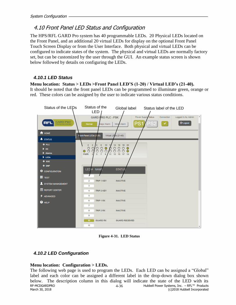
System Configuration
RF-MCDGARDPRO Hubbell Power Systems, Inc. – RFL™ Products March 30, 2018 (c)2018 Hubbell Incorporated
4-36
4.10 Front Panel LED Status and Configuration
The HPS/RFL GARD Pro system has 40 programmable LEDs. 20 Physical LEDs located on
the Front Panel, and an additional 20 virtual LEDs for display on the optional Front Panel
Touch Screen Display or from the User Interface. Both physical and virtual LEDs can be
configured to indicate states of the system. The physical and virtual LEDs are normally factory
set, but can be customized by the user through the GUI. An example status screen is shown
below followed by details on configuring the LEDs.
4.10.1 LED Status
Menu location: Status > LEDs >Front Panel LED’S (1-20) / Virtual LED’s (21-40).
It should be noted that the front panel LEDs can be programmed to illuminate green, orange or
red. These colors can be assigned by the user to indicate various status conditions.
Status of the LEDs Global label Status label of the LEDStatus of the
LED
Figure 4-31. LED Status
4.10.2 LED Configuration
Menu location: Configuration > LEDs.
The following web page is used to program the LEDs. Each LED can be assigned a “Global”
label and each color can be assigned a different label in the drop-down dialog box shown
below. The description column in this dialog will indicate the state of the LED with its

System Configuration
RF-MCDGARDPRO Hubbell Power Systems, Inc. – RFL™ Products March 30, 2018 (c)2018 Hubbell Incorporated
4-37
assigned color. The control logic in the next column can be set as required by the user with its
associated logic bit that can be driven either high or low. Once all the changes are made click
“Save” to make the changes permanent. A confirmation window will appear at the bottom right
of the web page.
Note: Virtual LED’s are provided for viewing on the optional touch screen display.
Set the global LED label first
by typing directly in the field
1 2 3 4 5
Figure 4-32. LED Configuration
1. LED: Indicates the LED color in descending priority.
2. Description: The LED active state. In the example shown the LED will turn red when
“HMIOUT Bit 7” is high.
If multiple conditions are true, the LEDs will be displayed with the following priorities.
Table 4-4 LED Priorites
None Highest
Red
Amber
Green Lowest
3. HMI/Logic: This drop-down menu will allow the user to set the control logic to the
following:
None
Logic
HmiIn
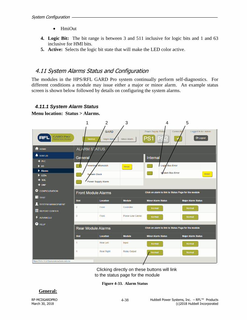
System Configuration
RF-MCDGARDPRO Hubbell Power Systems, Inc. – RFL™ Products March 30, 2018 (c)2018 Hubbell Incorporated
4-38
HmiOut
4. Logic Bit: The bit range is between 3 and 511 inclusive for logic bits and 1 and 63
inclusive for HMI bits.
5. Active: Selects the logic bit state that will make the LED color active.
4.11 System Alarms Status and Configuration
The modules in the HPS/RFL GARD Pro system continually perform self-diagnostics. For
different conditions a module may issue either a major or minor alarm. An example status
screen is shown below followed by details on configuring the system alarms.
4.11.1 System Alarm Status
Menu location: Status > Alarms.
Clicking directly on these buttons will link
to the status page for the module
1 32 4 5
Figure 4-33. Alarm Status
General:

System Configuration
RF-MCDGARDPRO Hubbell Power Systems, Inc. – RFL™ Products March 30, 2018 (c)2018 Hubbell Incorporated
4-39
1. Inventory Mismatch: The alarm will become active when a module is removed from,
or moved to a different slot in the chassis or inserted into a vacant slot. The alarm will
also become active if the module is not responding on the control bus. If the card is
returned to the chassis in the same slot the alarm will clear automatically within one
minute. Pressing “Reset” will record the current inventory and reset the alarm.
There is a four minute delay before a module drops out of inventory. Cards are added to
inventory almost instantly.
Note:
An SOE entry is made if an inventory mismatch alarm occurs.
2. System Clock: Alarm will become active if the expected clock source is not healthy.
See Configuration > System > Clock Tab
3. Power Supply Alarm: The alarm goes active when a power supply output voltage is
measured to be outside of the acceptable range.
Internal:
4. Logic Bus Error: Alarm will become active if a problem or conflict is detected on the
logic bus. Always review the logic configuration to ensure that no bits are being driven
by more than one source.
CAUTION
This is a serious alarm, contact HPS/RFL for assistance.
5. System Bus Error: Goes active when unexpected messages are detected on the control
bus. The alarm will stay active until manually cleared by pressing “Reset.”
CAUTION
This is a serious alarm, contact HPS/RFL for assistance.
4.11.2 System Alarm Configuration
Menu location: Configuration > Alarms.
The following web page is used to set system alarm levels in the HPS/RFL GARD Pro system.
The alarm configuration web page lists each module in a HPS/RFL GARD Pro system and
allows mapping of the modules alarm state to the HPS/RFL GARD Pro system alarm contacts.
On this web page the user can map any module alarm to activate the HPS/RFL GARD Pro
system
- major alarm,
- minor alarm,
- both major and minor alarms or
- no alarms.
Under normal operating conditions when the alarm conditions are healthy the relays are
energized. In an alarm or alert state the relays will be in the de-energized position.
Note:
All relay contacts are labeled in the de-energized position.
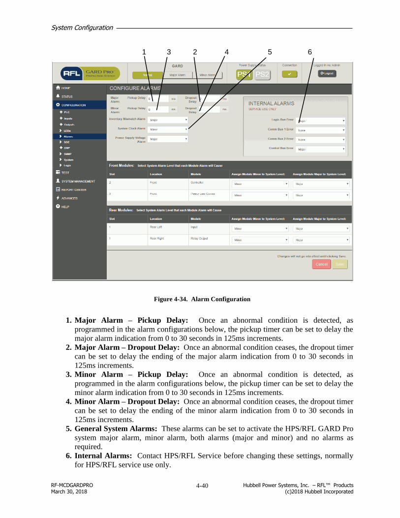
System Configuration
RF-MCDGARDPRO Hubbell Power Systems, Inc. – RFL™ Products March 30, 2018 (c)2018 Hubbell Incorporated
4-40
1 23 4 5 6
Figure 4-34. Alarm Configuration
1. Major Alarm – Pickup Delay: Once an abnormal condition is detected, as
programmed in the alarm configurations below, the pickup timer can be set to delay the
major alarm indication from 0 to 30 seconds in 125ms increments.
2. Major Alarm – Dropout Delay: Once an abnormal condition ceases, the dropout timer
can be set to delay the ending of the major alarm indication from 0 to 30 seconds in
125ms increments.
3. Minor Alarm – Pickup Delay: Once an abnormal condition is detected, as
programmed in the alarm configurations below, the pickup timer can be set to delay the
minor alarm indication from 0 to 30 seconds in 125ms increments.
4. Minor Alarm – Dropout Delay: Once an abnormal condition ceases, the dropout timer
can be set to delay the ending of the minor alarm indication from 0 to 30 seconds in
125ms increments.
5. General System Alarms: These alarms can be set to activate the HPS/RFL GARD Pro
system major alarm, minor alarm, both alarms (major and minor) and no alarms as
required.
6. Internal Alarms: Contact HPS/RFL Service before changing these settings, normally
for HPS/RFL service use only.

System Configuration
RF-MCDGARDPRO Hubbell Power Systems, Inc. – RFL™ Products March 30, 2018 (c)2018 Hubbell Incorporated
4-41
Please note that the alarms as shown in the GUI will not use the delay settings, the alarm
contacts on the rear of the chassis will use these settings only.
4.12 SOE Status and Configuration
A Recording of every “Sequence of Event” can be downloaded and saved. The SOE log is
stored in the GARD in non-volatile RAM. Currently 609 events can be stored in the HPS/RFL
GARD Pro system database.
4.12.1 Retrieving SOE Records
Menu location: Status > SOE > Records.
The following web page will display.
1 32 4 5 6 7
Figure 4-35. Retrieving SOE Records
1. Last Updated: Gives the date and time of the last update of the SOE display.
2. Record #: The number of the record which corresponds to the timestamp. Clicking to
the left of the number will display trigger details for this record. See the following web
page.
3. Date Time: Gives the date and time the SOE was logged. The time is given in hours,
minutes, seconds and milliseconds.

System Configuration
RF-MCDGARDPRO Hubbell Power Systems, Inc. – RFL™ Products March 30, 2018 (c)2018 Hubbell Incorporated
4-42
4. Scroll Bar: Slide this bar to select the range of the SOE display. This allows selection
of only one date or window of time, as needed. The date and time of the displayed SOE
will display below the scroll bar.
5. Trigger Label: The description of the SOE trigger, as programed in the configuration
web page.
6. Status: When the trigger changes to this state it generates the SOE record. In the
example, record 1 shows that Trigger 10, Rx low level, changed from high to low, thus
generating the SOE record.
7. Reload, Download and Clear All buttons: Click the “Reload” button to refresh the
SOE display. Click the “Download” button to save the web page to your computer.
Click the “Clear All” button to clear all SOE records from the database.

System Configuration
RF-MCDGARDPRO Hubbell Power Systems, Inc. – RFL™ Products March 30, 2018 (c)2018 Hubbell Incorporated
4-43
4.12.1.1 SOE Record Details (Triggers)
After selecting the “›” button the page moves the user from the Reports tab to the Details tab.
The user can then navigate to the next record by returning to the Reports tab or clicking Older
or Newer on the Details tab.
For example, clicking the “›” symbol next to SOE record # 1 will display the details page for
record #1. This contains the state of all currently enabled SOE triggers at the instant the record
was generated. There are a total of 191 triggers that can be enabled for recording.
The screenshot below shows that trigger #10 has changed state, generating an SOE record.
Note:
A trigger that changes state will show as red text with a light red background.
State
The record
being viewed
Trigger
Number
Changed state will be
highlighted in red if changedTrigger
Label
Figure 4-36. SOE Triggers
Selecting the Older or Newer buttons moves the user to the next record.

System Configuration
RF-MCDGARDPRO Hubbell Power Systems, Inc. – RFL™ Products March 30, 2018 (c)2018 Hubbell Incorporated
4-44
4.12.1.2 SOE Records Details (Logic Bits)
Menu location: Status > SOE > (Logic Labels).
This web page shows the state of all system logic bits at the instant the SOE record was
generated. Mostly used by HPS/RFL Service for event analysis.
Logic bit label as defined in the
logic bit labels name pageBit Number
Shows the status of each logic bit
at the time of the event
Figure 4-37. SOE Record Details (Logic Bits)

System Configuration
RF-MCDGARDPRO Hubbell Power Systems, Inc. – RFL™ Products March 30, 2018 (c)2018 Hubbell Incorporated
4-45
4.12.1.3 SOE Records Details (Logic Table)
Menu location: Status > SOE > Details (Logic Table).
This web page contains the same data as the logic bit list, but presents it in table format.
Mostly used by HPS/RFL Service for event analysis.
Selecting the Older or Newer buttons moves the user to the next record.
In the example shown the status of the bits 8 through
15 are 00000010
Figure 4-38. SOE Record Details (Logic Table)

System Configuration
RF-MCDGARDPRO Hubbell Power Systems, Inc. – RFL™ Products March 30, 2018 (c)2018 Hubbell Incorporated
4-46
4.12.2 SOE Counters
This “Read Only” web page will inform the user of the count of enabled triggers. The count
can be reset by clicking the “Reset’ button.
Menu location: Status > SOE > Counters.
1 2 3 4
Figure 4-39. SOE Counters
1. Trigger Number: The trigger number column identifies the trigger number used in the
custom logic file. The first two numbers are reserved by the HPS/RFL GARD Pro
system and cannot be assigned or changed by the user.
2. Label: Label for each of the triggers.
3. Count: Count for the enabled trigger.
4. Reset Counters: Resets the counters.

System Configuration
RF-MCDGARDPRO Hubbell Power Systems, Inc. – RFL™ Products March 30, 2018 (c)2018 Hubbell Incorporated
4-47
4.12.3 SOE Configuration (Triggers and Labels)
Menu location: Configuration > SOE
The following web page will allow the user to enable SOE triggers and assign trigger labels that
will be displayed in the SOE record. SOE triggers are defined in the system logic.
1 32
Figure 4-40. SOE Configuration
1. Trigger #: The SOE recorder has 191 user programmable SOE triggers. The trigger #
column identifies the trigger number used in the custom logic file.
2. Trigger Label: User definable label for each of the 191 triggers. Change this field by
changing the text and selecting “Save” once all the changes are made to the web page.
3. Enabled: Check this box to enable the trigger.
4.13 Logic Configuration
Menu location: Configuration > Logic
Input and output mapping can also be performed in section 4.9.4.3 and 4.9.4.7 respectively.
Please refer to these sections for details on I/O input and output mapping. The example web
page below has the “Options” tab clicked.
4.13.1 Logic Options
To allow flexibility in the logic without modifying the logic programming, an options setting
section is provided. Option setting choices are defined in the system logic. In the following

System Configuration
RF-MCDGARDPRO Hubbell Power Systems, Inc. – RFL™ Products March 30, 2018 (c)2018 Hubbell Incorporated
4-48
web page example various logic options can be enabled or disabled or set, such as polarity, and
shift direction.
Go to Section 4.9.4.3 for Input Mapping
Go to Section 4.9.4.7 for Output Mapping
Remember to click “Save” for the
settings to become permanent
Figure 4-41. Logic Options

System Configuration
RF-MCDGARDPRO Hubbell Power Systems, Inc. – RFL™ Products March 30, 2018 (c)2018 Hubbell Incorporated
4-49
4.13.2 Logic Timers
Menu location: Configuration > Logic (Logic Timers).
The available timers are dependent on the system logic files loaded into the HPS/RFL GARD
Pro system. Timer settings are from 0 to 32767ms in 0.25ms increments.
Timer settings
Remember to click “Save” for the
settings to become permanent
Figure 4-42. Logic Configuration, Timers

System Configuration
RF-MCDGARDPRO Hubbell Power Systems, Inc. – RFL™ Products March 30, 2018 (c)2018 Hubbell Incorporated
4-50
4.14 System Settings
Menu location: Configuration > System (Labels/Ethernet).
4.14.1 General Information and IP details
This web page can be used to identify the complete HPS/RFL GARD Pro system, for example
the substation name. Additional identifiers can be added as required. Also listed here is IP
address information normally only changed by the system administrator.
Enter label information
here as required
1 2 3 45 6 7
Time since last
power cycle or reboot
89
Figure 4-43. System Configuration, Ethernet Labels
1. Active Port: Displays which of the two Ethernet ports, front or back is active.
2. Rear IP Address: Displays the current IP address for the rear Ethernet port. For
additional security the user must be connected to the front Ethernet port and have the
proper security access level authorization to change the address of the rear Ethernet port.
When connected to the front Ethernet port, enter the desired address and click “Save.”
3. Rear Netmask: Indicates the subnet mask of the rear port. The administrator who
assigns the IP address will also assign the netmask. All systems on the same subnet
must use the same subnet mask.
4. Rear Gateway: Displays the rear gateway IP address for the corresponding Ethernet
port.
5. Front IP Address: Displays the IP address of the front Ethernet port. This address is
programmed at the factory and cannot be changed.

System Configuration
RF-MCDGARDPRO Hubbell Power Systems, Inc. – RFL™ Products March 30, 2018 (c)2018 Hubbell Incorporated
4-51
6. Front Netmask: Displays the subnet mask of the front Ethernet port. The subnet mask
is programmed at the factory and cannot be changed.
7. Front Gateway: Displays the front gateway IP address for the corresponding Ethernet
port (factory set).
8. Chassis Identification Number: HPS/RFL assigned number identifying the hardware
configuration. User changeable in case of hardware reconfiguration.
9. Chassis Serial Number: HPS/RFL assigned serial number unique to an assembled
chassis. The Serial number can also be found on the side of the chassis. User
changeable in case of controller hardware being replaced.
4.14.2 System Settings – Clock
Menu location: Configuration > System (Clock).
This web page is used to select the RTC (real time clock) and manipulate the date and time if
required. On boot-up the web page will display whatever the RTC is programmed to. The date
and time will be grayed out in the web page when an external clock source is synchronized.
Remember to click “Save” to make the changes permanent.
1 2 3
4 5 6
Figure 4-44. System Configuration, Clock
1. Date: Displays the local date and time with offset from GMT.
2. Time: Time setting field.
3. Date Setting Utility: Can be set to a specific date, set to “Today” or cleared.
4. Time Zone Offset: When using GPS, sets the time offset from +12 to -12 hours.

System Configuration
RF-MCDGARDPRO Hubbell Power Systems, Inc. – RFL™ Products March 30, 2018 (c)2018 Hubbell Incorporated
4-52
5. Source of System Clock Alarm: Sets the expected timing source for alarm purposes,
set to “None” if no external timing source is used. The choices are:
None
GPS
IRIG-B
IRIG-B/1pps (one pulse per second)
6. Clock Source: Indicates the clock source and its state.
4.15 Advanced Settings
The following web pages are normally used for factory programming and troubleshooting only.
CAUTION
Improper settings can cause system outage
Only advanced users should access these pages which are used to program labels for the
HPS/RFL GARD Pro system “logic bits” and “HMI bits.”
4.15.1 Logic Bits
Menu location: Advanced > Logic Bits.
This table can be scrolled down through values from 3 to 511. Note the first three bits are
reserved for use by the system and cannot be changed. Remember to click “Save” once
changes are made.
The user can enter label information here. This information will also show on the “Logic Details” for SOE records web page. .Logic Bit Number
Logic Bits reserved by
the system
Shows the state of a
particular logic bit
number for that row
Figure 4-45. Advanced Settings, Logic Bits

System Configuration
RF-MCDGARDPRO Hubbell Power Systems, Inc. – RFL™ Products March 30, 2018 (c)2018 Hubbell Incorporated
4-53
4.15.2 HMI Bits
Menu location: Advanced > HMI Bits.
This table can be scrolled down through values from 2 to 63. There are two tabs; one for “HMI
In” and one for “HMI Out”. The “HMI In” web page is shown below and the “HMI Out” page
is similar.
Note
The first two bits are reserved for use by the system and cannot be changed.
HMI Bits reserved
by the systemHMI Bit Number
The user can enter
label information here
Shows the state of a
particular HMI bit number
for that row
Figure 4-46. Advanced Settings, HMI Bits

System Configuration
RF-MCDGARDPRO Hubbell Power Systems, Inc. – RFL™ Products March 30, 2018 (c)2018 Hubbell Incorporated
4-54
4.15.3 Touch Screen Display Wake-up
From the pull down menu on your PC select “Settings/Advanced/Touch Screen Display”

System Configuration
RF-MCDGARDPRO Hubbell Power Systems, Inc. – RFL™ Products March 30, 2018 (c)2018 Hubbell Incorporated
4-55
The TSD can Wake-Up to a designated screen. With a Laptop or PC connected to the GARD
chassis select Advanced/Touch Screen Display. A designated wake-up HMIOUT bit can be set
high to display the required screen; bits 2 – 63 are available, bits 0 and 1 are reserved. To
designate the wake-up bit:
1. Set the bit in the “Wake-up HMIOUT Bit” drop down menu.
2. Select the “Wakeup Page”
3. Click “Save”
Figure 4-47. TSD Wake-Up Settings

System Configuration
RF-MCDGARDPRO Hubbell Power Systems, Inc. – RFL™ Products March 30, 2018 (c)2018 Hubbell Incorporated
4-56
4.15.4 TSD push button interface configuration
The following sub-section gives details on configuring the Push Button Interface.
The following web page will appear. This web page will allow the user to configure which
input bits appear on the “Push Button Interface.” Up to 8 Push Buttons can be configured.
Click “Save” after configuring the web page.
Sets the title of the buttons that will be seen on the TSD (15 Character Limit)
Selects the number of HMI "In Bits" that are to be manipulated on the "Push Button Interface", selecting enables the remaining options
When + Icon is selected the Push Button color options and preview window will open.
Sets the TYPE of button (Toggle or Pulse)
Check to enable Button
on Touch Screen Display
Figure 4-48. TSD Push Button Interface Configuration.
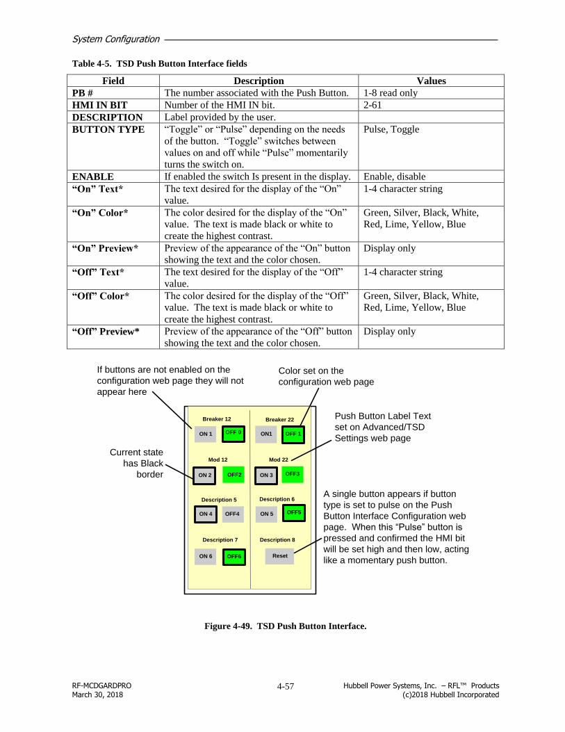
System Configuration
RF-MCDGARDPRO Hubbell Power Systems, Inc. – RFL™ Products March 30, 2018 (c)2018 Hubbell Incorporated
4-57
Table 4-5. TSD Push Button Interface fields
Field Description Values
PB # The number associated with the Push Button. 1-8 read only
HMI IN BIT Number of the HMI IN bit. 2-61
DESCRIPTION Label provided by the user.
BUTTON TYPE “Toggle” or “Pulse” depending on the needs
of the button. “Toggle” switches between
values on and off while “Pulse” momentarily
turns the switch on.
Pulse, Toggle
ENABLE If enabled the switch Is present in the display. Enable, disable
“On” Text* The text desired for the display of the “On”
value.
1-4 character string
“On” Color* The color desired for the display of the “On”
value. The text is made black or white to
create the highest contrast.
Green, Silver, Black, White,
Red, Lime, Yellow, Blue
“On” Preview* Preview of the appearance of the “On” button
showing the text and the color chosen.
Display only
“Off” Text* The text desired for the display of the “Off”
value.
1-4 character string
“Off” Color* The color desired for the display of the “Off”
value. The text is made black or white to
create the highest contrast.
Green, Silver, Black, White,
Red, Lime, Yellow, Blue
“Off” Preview* Preview of the appearance of the “Off” button
showing the text and the color chosen.
Display only
If buttons are not enabled on the
configuration web page they will not
appear here
Current state
has Black
border
Color set on the
configuration web page
Push Button Label Text
set on Advanced/TSD
Settings web page
A single button appears if button
type is set to pulse on the Push
Button Interface Configuration web
page. When this “Pulse” button is
pressed and confirmed the HMI bit
will be set high and then low, acting
like a momentary push button.
OFF 0
Breaker 12
ON 1
ON 2 OFF2
Breaker 22
OFF 1ON1
ON 4
ON 6
ON 3 OFF3
OFF4 ON 5
Reset
Mod 12 Mod 22
OFF5
OFF6
Description 5 Description 6
Description 7 Description 8
Figure 4-49. TSD Push Button Interface.

System Configuration
RF-MCDGARDPRO Hubbell Power Systems, Inc. – RFL™ Products March 30, 2018 (c)2018 Hubbell Incorporated
4-58
If a Push Button Interface web page is not configured (i.e. Some or No Buttons are enabled)
the TSD will automatically display a Blank Screen or a Blank Button as Shown below.
OFF0
Breaker 12
ON 1
ON 2 OFF2
ON 4
ON 6
OFF4 ON 5
Reset
Mod 12
OFF5
OFF6
Description 5 Description 6
Description 7 Description 8
“Alert are you sure you
want to change this setting
to OFF?
OK X
If a selection is made a pop-up
will appear to confirm the
selection.
Figure 4-50. TSD Blank Button

System Configuration
RF-MCDGARDPRO Hubbell Power Systems, Inc. – RFL™ Products March 30, 2018 (c)2018 Hubbell Incorporated
4-59
4.16 DNP3
4.16.1 Description
DNP3 is a communications protocol to allow automatic collection of data from remote devices.
This provides communication for slower networks and Ethernet. Communications on an as-
needed basis reduces the overhead required.
The System Firmware version must be 2.2.0 or greater.
DNP (Distributed Network Protocol) is used by a “master” station (control center) to poll
multiple “slave” devices for status, usually over a wide geographic area. Since many devices
are involved and each device has many “points” or values, a class-based polling system is
applied, similar to an RBE (report-by-exception) scheme. Class 1 polls are done most
frequently, on the most important data, Class 2 less frequently, and Class 3 even less frequently.
When a Class 1, 2 or 3 poll is executed, the “slave” device only returns those values which have
changed state since the last poll. A Class 0 poll returns all values regardless of whether they
have changed state or not. For more information on Data Points see section 4.16.1.2.
4.16.1.1 Overview of HPS/RFL GARD Pro System DNP3
The HPS/RFL GARD Pro system controller board has factory installed software that allows the
user to take advantage of the robust and flexible features of the DNP communications protocol.
Once configured, the HPS/RFL GARD Pro system will communicate with up to two TCP/IP
and one RS-485 remote DNP master computers. The remote master computers poll the
HPS/RFL GARD Pro system for data.
DNP Master
Computer 1
RFL™ GARD
Pro™ System
DNP Slave Controller Board
DNP
Request
RS-485
Response
PLC Module
Counters
Analog Values Deadband
RFL™ GARD
Pro™ System
Logic
RFL™ GARD
Pro™ System
Counters
HMIDNP Master
Computer 2
Request
TCP/IP
Response
DNP Master
Computer 3
Request
Response
TCP/IP

System Configuration
RF-MCDGARDPRO Hubbell Power Systems, Inc. – RFL™ Products March 30, 2018 (c)2018 Hubbell Incorporated
4-60
The HPS/RFL GARD Pro system can send the following list of data to the master computers:
Table 4-6. HPS/RFL GARD Pro system list of DNP3 data points
HPS/RFL GARD Pro system
DNP Object Notes
Normal Change event
Source Description Labels3 units Description Type Var Type Var
System Logic
HMI input HMI Input 0-63 n/a Binary output 10 2 11 1 50 ms2
HMI output HMI Output 0-63 n/a Binary input 1 1 2 1 50 ms2
SOE Counters Counters of the SOE Triggers n/a 32-bit Binary Counter 20 1 22 1
SOE triggers SOE triggers 0-191 n/a Binary input 1 1 2 21 1 ms
2
PLC FSK
Analog Values
Tx Power Rx Level Reflected Power Signal-to-Noise Ratio Trans Hybrid Loss
dBm dB % dB dB
32-bit floating point 30 1 32 1
Counters
Trip 1 Key Trip 2 Key Trip 1 Rx Trip 2 Rx Rx Alarm Reflected Power Alarm
n/a 32-bit Binary 20 1 22 1
Internally these
counters are 8-bit
and rollover at 255
PLC On/Off
Analog Values
Tx Power Rx Level Reflected Power SNR
dBm dB % dB
32-bit floating point 30 1 32 1
Counters
Start 1 Start 2 Stop 1 Stop 2 Block Rx Reserve Key Checkback Tests Run Checkback Tests Passed Checkback Tests Failed
n/a 32-bit Binary 20 1 22 1
Internally these
counters are 8-bit
and rollover at 255
Note 1: For change events, SOE Trigger points will be reported with timestamps synchronized
to the HPS/RFL GARD Pro system clock and as reported in the Sequence of Events report.
Note 2: To be recorded as a DNP change event, the duration of the event must be a minimum
of 1 millisecond for SOE Trigger points or 50 milliseconds for HMI Out and HMI In.
Note 3: Functional Module Point labels can be configured through the appropriate DNP
configuration pages. To change the default labels for Functional Module Points navigate to the
appropriate tabs on the Configuration > DNP > point type pages.
The System Logic Point labels can be changed in the appropriate Configuration > SOE and
Advanced > HMI pages.
To make use of the DNP feature the user must configure the HPS/RFL GARD Pro system
appropriately using the “DNP3 Configuration” web page; Configuration > DNP > General.
This sets up the communication parameters allowing the HPS/RFL GARD Pro system to
connect with other devices.

System Configuration
RF-MCDGARDPRO Hubbell Power Systems, Inc. – RFL™ Products March 30, 2018 (c)2018 Hubbell Incorporated
4-61
Once the DNP configuration page is set other parameters such as the “Point list setting” web
pages can be configured.
Note: DNP will not be functional until at least one DNP point is enabled.
To reduce polling traffic, the GARD Pro can be set to send unsolicited messages to any of the
DNP3 masters. Unsolicited messages are sent when a binary object changes state or an analog
value changes by more than a user adjustable deadband setting. The unsolicited message
capability is disabled by default and must be enabled via an “Enable Unsolicited Messages”
command from the DNP master.
Note:
Since the unsolicited messaging setting of the GARD Pro is not stored in NVRAM, it must be
enabled by the DNP Master each time the GARD Pro is power-cycled."
4.16.1.2 DNP3 Features
The HPS/RFL GARD Pro system provides the following features to aid managing the system.
4.16.1.2.1 Data Point Refresh Time
In some cases the refresh rate of DNP points may be slower than the actual event duration.
This means it is possible that events which occur within the refresh time will be missed and not
recorded as a DNP change event.
In the HPS/RFL GARD Pro system the refresh time for SOE Trigger DNP points is 1
millisecond. For HMI In and HMI Out the refresh time is 50 milliseconds.
In order for an event to be recorded as a DNP change event, the duration of each state must be a
minimum of 1 millisecond for SOE Trigger points or 50 milliseconds for HMI Out and HMI In.
4.16.1.2.2 Data Point Index manual assignment
Manually assigned data point indexes is provided as an alternative to auto assigned. This
requires the user to manually assign each data point index. Indexes can be freely assigned
within an object type as long as there are no duplicates indexes.
Manual mode also includes a default index assignment option which applies a default index for
each point. Default indexes for points sourced from installed modules, where available, are
based on the slot number and location.

System Configuration
RF-MCDGARDPRO Hubbell Power Systems, Inc. – RFL™ Products March 30, 2018 (c)2018 Hubbell Incorporated
4-62
4.16.1.2.3 Data Point Index manual default assignment rules
The DNP data point index is a sequential number assigned to a data point of a particular Object
Type. Each data point within an Object Type has a unique data point index.
Index rules apply to each object type independently.
Each physical slot has 100 points reserved in the index space.
Index ranges for each slot are as follows:
o Slot 1 = 200-299
o Slot 2 = 300-399
o Slot 3 = 400-499
o Slot 4 = 500-599
o Slot 5 = 600-699
o Slot 6 = 700-799
o Slot 7 = 800-899
o Slot 8 = 900-999
o Slot 9 = 1000-1099
o Slot 10 = 1100-1199
Default index ranges by slot are divided by front, rear top/right and rear bottom/left. The
divided ranges are as follows:
o Front: n*100 + 0…63 (64 total)
o Rear: n*100 + 64…99
Within the rear: Top/Right: 64-81 (18 total), Bottom/Left: 72-99 (18 total)
4.16.1.2.4 Data Point Index auto-assign rules
In auto implementation the data point index is assigned when the points are enabled in the point
list settings. This means that the data point indexes will change as points are enabled or
disabled.
Example of auto-index numbering: If data point 1, 3 and 5 are enabled the device will assign
these with an index of 0, 1 and 2. If data point 2 is added data point 3 and 5 will become index
2 and 3.
When using auto index assignments a priority rule is used to sequential assign index numbers
within a point type. Priority is determined by the source of the point and the slot number and
location. The priority rules are as follows:
System Logic Points (SOE triggers, HMI bits)
Lowest Slot Number
Front Slot Position
Rear top/right to Rear bottom/left
Caution:
Switching to manual retains the existing the auto-index assignments.
If you switch back to auto this will renumber all index assignments according to the auto-assign
rules.

System Configuration
RF-MCDGARDPRO Hubbell Power Systems, Inc. – RFL™ Products March 30, 2018 (c)2018 Hubbell Incorporated
4-63
4.16.2 DNP Configuration
4.16.2.1 DNP - General Configuration page
Configuration > DNP > General
This screen allows the user to configure the DNP communications with the DNP master(s).

System Configuration
RF-MCDGARDPRO Hubbell Power Systems, Inc. – RFL™ Products March 30, 2018 (c)2018 Hubbell Incorporated
4-64
Table 4-7. General Configuration fields
Field Name Description Allowed values Default setting
Enable DNP
Slave
DNP service is turned on globally for the HPS/RFL GARD Pro
system. DNP communications are only active if at least one
data point is turned on.
ON, OFF OFF
Point Index
Mapping
Auto sets data points sequentially without gaps and reorders the
list as new points are added or taken away. Manual mode
allows for gaps between index numbers between index numbers,
and allows for fixed index values. This is a global control for
all point list pages.
Auto, Manual Auto
Link Layer
Addressing
Determine the Source and Destination addresses for the DNP
link layer.
1-255
(increment = 1)
Source = 3,
Destination = 4
TCP/IP
Master 1
Allows the HPS/RFL GARD Pro system DNP slave to
communicate to a DNP master which is defined by the IP
address and port number.
ON, OFF OFF
Master 1 IP The IP address of TCP/IP Master 1 for which communications
will be established. This field is disabled if “TCP/IP Master 1”
is set to OFF.
n.n.n.n (valid
IP address)
0.0.0.0 (slave
responds to any
master.)
Master 1
Port #
The port number of TCP/IP Master 1 for which communications
will be established. This field is disabled if “TCP/IP Master 1”
is set to OFF
2000 – 65535
(increment 1)
20000
TCP/IP
Master 2
Allows the HPS/RFL GARD Pro system DNP slave to
communicate to a DNP master which is defined by the IP
address and port number.
ON, OFF OFF
Master 2 IP The IP address of TCP/IP Master 2 for which communications
will be established. This field is disabled if “TCP/IP Master 2”
is set to OFF.
n.n.n.n (valid
IP address)
0.0.0.0 (slave
respond to any
master.)
Master 2
Port #
The port number of TCP/IP Master 2 for which communications
will be established. This field is disabled if “TCP/IP Master 2”
is set to OFF.
2000 – 65535
(increment 1)
20001
RS-485
Master
Allows the HPS/RFL GARD Pro system DNP slave to
communicate to an RS-485 DNP master.
ON, OFF OFF
RS-485
Mode
Determines whether the RS-485 port uses 2-wire or 4-wire
mode to communicate with the RS-485 master. This field is
disabled if “RS-485 Master” is set to OFF.
2-wire, 4-wire 4-wire
Data
Format
The serial data format of the RS-485 communication. This field
is disabled if “RS-485 Master” is set to OFF.
Parity/Stop bit
Serial
Data Rate
None Even Odd
1 2 1 2 1 2
300 X X X X
2400 X X X X X X
4800 X X X X X X
9600 X X X X X X
See table 9600-None-1
Cancel Cancel any changes made in the web page, and reset them to the values when the page was first
opened. Clicking this button brings up a confirmation dialog.
This button is disabled if no changes were made.
Save Writes the changes made to the settings in the web page. Clicking this button brings up a
confirmation dialog.
This button is disabled if no changes were made.

System Configuration
RF-MCDGARDPRO Hubbell Power Systems, Inc. – RFL™ Products March 30, 2018 (c)2018 Hubbell Incorporated
4-65
4.16.2.2 DNP Point Type Configuration
The following descriptions apply to all “Type” configuration pages: Type 1, Type 10, Type 20,
and Type 30.
4.16.2.3 Type 1 – Binary Input
Configuration > DNP > “Type 1 – Binary Input”
This page lists any DNP Type 1 Binary Input points available for reporting. System Logic HMI
Outputs and SOE Triggers are always available. However, only those points which are enabled
for SOE recording are available for DNP reporting. Points from different sources are organized
on separate tabs.
NOTE: Only those SOE Triggers which are enabled for recording in the Config > SOE page
are displayed in this page.

System Configuration
RF-MCDGARDPRO Hubbell Power Systems, Inc. – RFL™ Products March 30, 2018 (c)2018 Hubbell Incorporated
4-66
Table 4-8. DNP Type Configuration Field Descriptions
Name Description Values
Index Indicates to the user whether or not it is set up for
Auto or Manual indexing. This is set on the Config
> DNP > General page.
Auto, Manual
“All”
control -
Class
The Class selected with the “All” button applies to
all points in the table. If “Enable” is unchecked the
Class selection tool is disabled.
Class 1, Class 2, Class 3, Class 0
“All”
control -
Enable
Selecting the Enable or Disable from the All button
applies to all points in the table.
Enable, Disable
Index This column shows the index value of the point in
the same row. For Auto, the Index field will auto-
update as points are enabled and disabled, to indicate
to the user that the point list is being dynamically
assigned on the points which are enabled/disabled .
Control disabled if: Indexing mode = Auto
Auto- the index number is assigned and cannot
be modified.
Manual- any number within the valid range
defined by manual indexing rules described
above, as long as the index value is not already
assigned to another point of the same type.
Parameter
#
This is the fixed HPS/RFL GARD Pro system
parameter #. For example, HMIOUT60, while it can
have an index value manually assigned, will always
have parameter # of 60. This field allows the user to
assign connections between DNP points and their
index numbers, back to the HPS/RFL GARD Pro
system and logic.
System/functional module parameter number.
Label For functional module points this field is a user
entered label. For system logic points this field is
read only. SOE Trigger labels can be changed in the
Configuration > SOE page, and HMI labels can be
changed in the "Advanced > HMI Bits page
System logic points: HMI labels and SOE labels
Functional module points: Default, User edit
Class This determines the class of the associated DNP
point in the same row. Default class:
Type 1 - Class 1
Type 10 - Class 1
Type 20 - Class 3
Type 30 - Class 2
The default is Class 1 and control is disabled if:
DNP Point enable = “OFF”
Class 1, Class 2, Class 3, Class 0.
Enable This control determines whether or not the associated
point will be included in the DNP engine for
reporting.
The default is “Off”.
On, Off (check box control, as shown in
screenshot)
Default
Index
Assigns point index values according to GARD Pro
defaults.
Available only with Point Index Mapping set to
Manual (Configuration > DNP > General)
GARD Pro assigns HMIOUT bits from 0 to 63
according to the HMIOUT bit number.
Cancel Resets any changes to the values when the page was first opened. Clicking this button will bring up a
confirmation dialog.
This button is disabled if no changes were made.
Save This control will write the changes made to the settings in the web page. Clicking this button will bring
up a confirmation dialog.
This button is disabled if no changes were made.

System Configuration
RF-MCDGARDPRO Hubbell Power Systems, Inc. – RFL™ Products March 30, 2018 (c)2018 Hubbell Incorporated
4-67
4.16.2.4 Type 10 – Binary Output
Configuration > DNP > Type 10 – Binary Output
This page lists any DNP Type 10 Binary Outputs points available for reporting. System Logic
HMI Inputs are always available. Points from different sources are organized on separate tabs.
4.16.2.5 Type 20 – Counter
Configuration > DNP > Type 20 – Counter
NOTE: Only those SOE Triggers which are enabled for recording in the Config > SOE page
are displayed in this page.
This page lists any DNP Type 20 Counter points available for reporting. System Logic SOE
Trigger Counters are always available. Additional points may be available when DNP-enabled
modules are installed. Points from different sources are organized on separate tabs.
If the SOE triggers are configured for DNP in this page, and the user enables more SOE triggers
in the Config > SOE page at a later time, those newly enabled SOE triggers will be disabled by
default. Therefore index numbers won’t change if using Auto-index mode.

System Configuration
RF-MCDGARDPRO Hubbell Power Systems, Inc. – RFL™ Products March 30, 2018 (c)2018 Hubbell Incorporated
4-68
If an SOE trigger is enabled for DNP recording/reporting, the control to enable/disable the SOE
trigger in the Config > SOE page will be disabled. Any SOE trigger which is enabled for DNP
cannot be disabled for SOE recording until it has been disabled for DNP. This is to ensure the
integrity of the DNP point list indexes.
The first tab configures the SOE counters

System Configuration
RF-MCDGARDPRO Hubbell Power Systems, Inc. – RFL™ Products March 30, 2018 (c)2018 Hubbell Incorporated
4-69
The remaining tabs configure any points available as supported by DNP-capable modules such
as the PLC modules.

System Configuration
RF-MCDGARDPRO Hubbell Power Systems, Inc. – RFL™ Products March 30, 2018 (c)2018 Hubbell Incorporated
4-70
4.16.2.6 Type 30 – Analog
Configuration > DNP > Type 30 – Analog
This page lists any DNP Type 30 Analog points available for reporting. This option is only
available when supporting modules are installed. Points from different sources are organized on
separate tabs.
4.16.2.6.1 Deadband:
Specifies the integer value, in the units of the particular point, by which an analog value must
change before it will be reported at the next poll or generating an unsolicited message, if
configured.
The units used for the deadband setting depend on the measurement type. For example,
Reflected Power is measured in percent. So a deadband setting of 20 requires the Reflected
Power to change by +/- 20% before the GARD Pro will report a change in value to the DNP
master.

System Configuration
RF-MCDGARDPRO Hubbell Power Systems, Inc. – RFL™ Products March 30, 2018 (c)2018 Hubbell Incorporated
4-71
The “deadband” value operates per-point. Each point in the DNP analog settings has its own
deadband value which the user sets on this page.
4.16.3 DNP Status Webpages
4.16.3.1 “General” tab
Status > DNP > General
This page shows general status of the DNP masters. There is also an option to download a
“DNP Profile” which is a report of the HPS/RFL GARD Pro system DNP capabilities, and also
the current configuration.

System Configuration
RF-MCDGARDPRO Hubbell Power Systems, Inc. – RFL™ Products March 30, 2018 (c)2018 Hubbell Incorporated
4-72
Table 4-9. DNP Status fields
Name Description Values
DNP Status: Displays the status of the HPS/RFL GARD Pro
system DNP engine. Based on the setting in the
Config > DNP > General page.
Disabled (gray outline), Enabled
(green outline)
GARD Pro
(Source)
The Link Layer source address. The address of the
GARD Pro DNP slave.
This displays the value set for
Configuration > DNP > General
GARD Pro (Source)
DNP Master
(Destination)
The Link Layer destination address. The address of
the DNP Master to which the GARD Pro will
report.
This displays the value set for
Configuration > DNP > General
DNP Master (Destination)
TCP/IP Master
1:
Displays the status of the HPS/RFL GARD Pro
system DNP reporting to TCP/IP Master 1. Based
on the setting in the Config > DNP > General page.
Disabled (gray outline), Enabled
(green outline)
Master 1 IP: Displays the programmed IP address for the TCP/IP
Master 1. Based on the setting in the Config > DNP
> General page.
n/a (gray outline – if TCP/IP
Master 1 disabled),
IP address for TCP/IP Master 1
Master 1 Port
#:
Displays the programmed port number for the
TCP/IP Master 1. Based on the setting in the
Config > DNP > General page.
n/a (gray outline – if TCP/IP
Master 1 disabled),
Port # for TCP/IP Master 1
TCP/IP Master
2:
Displays the status of the HPS/RFL GARD Pro
system DNP reporting to TCP/IP Master 2. Based
on the setting in the Config > DNP > General page.
Disabled (gray outline), Enabled
(green outline)
Master 2 IP: Displays the programmed IP address for the TCP/IP
Master 2. Based on the setting in the Config > DNP
> General page.
n/a (gray outline – if TCP/IP
Master 2 disabled),
IP address for TCP/IP Master 2
Master 2 Port
#:
Displays the programmed port number for the
TCP/IP Master 2. Based on the setting in the
Config > DNP > General page.
n/a (gray outline – if TCP/IP
Master 2 disabled), Port # for
TCP/IP Master 2
RS-485
Master:
Displays the status of the HPS/RFL GARD Pro
system DNP reporting to the RS-485 Master. Based
on the setting in the Config > DNP > General page.
Disabled (gray outline), Enabled
(green outline)
RS-485 Mode: Displays the programmed communication mode for
GARD Pro RS-485 master. Based on the setting in
the Config > DNP > General page.
n/a (gray 2-wire/4-wire outline –
RS-485 disabled),
communication mode for RS-485
master
Data format: Displays the programmed data format for the RS-
485 Master. Based on the setting in the Config >
DNP > General page.
n/a (gray outline – if RS-485
Master disabled),
data format for RS-485 master
Download DNP
Profile:
Clicking this button opens the browser download dialog HPS/RFL GARD Pro system
“Save” dialog and prompt the user to save a .csv file which contains the DNP Profile
document of the HPS/RFL GARD Pro system. This report contains enabled points and
their classes and index numbers, as well as global parameters.

System Configuration
RF-MCDGARDPRO Hubbell Power Systems, Inc. – RFL™ Products March 30, 2018 (c)2018 Hubbell Incorporated
4-73
4.16.3.2 “Point List” tab
Status > DNP > General
The Point List displays all DNP points which are currently enabled for DNP reporting. Only
the Index numbers, Labels, data Source and Class settings are displayed here.
All object types are displayed together in one continuous list.
If a particular DNP point group has no DNP points enabled, then that group will not be
displayed on this page.
4.16.3.3 Field descriptions for DNP status
Points from different sources are organized on separate tabs.
The “Value” field is updated dynamically.
If a particular object type has no points enabled, the user will still be brought to this page, but
instead of seeing this table the user will see a message, “No points enabled for Type (n)”
The following descriptions apply to the DNP type-specific status pages.
Table 4-10. Field descriptions for DNP status
Name Description
Index The index number assigned to the parameter.
Parameter # Internal system parameter number.
Label The label assigned to the parameter.
Value The current value in that register.
Class The reporting class of that parameter – 1, 2, 3 or 0

System Configuration
RF-MCDGARDPRO Hubbell Power Systems, Inc. – RFL™ Products March 30, 2018 (c)2018 Hubbell Incorporated
4-74
4.16.3.4 Type 1 Binary Input
Status > DNP > “Type 1 – Binary Input”
4.16.3.5 Type 10 – Binary Output
Status > DNP > Binary Output

System Configuration
RF-MCDGARDPRO Hubbell Power Systems, Inc. – RFL™ Products March 30, 2018 (c)2018 Hubbell Incorporated
4-75
4.16.3.6 Type 20 Counter
Status > DNP > “Type 20 – Counter”

System Configuration
RF-MCDGARDPRO Hubbell Power Systems, Inc. – RFL™ Products March 30, 2018 (c)2018 Hubbell Incorporated
4-76
4.16.3.7 Type 30 Analog Input
Status -> DNP > “Type 30 – Analog Input”
4.16.4 DNP TSD Status pages
4.16.4.1 TSD Menu Page: Home > Status

System Configuration
RF-MCDGARDPRO Hubbell Power Systems, Inc. – RFL™ Products March 30, 2018 (c)2018 Hubbell Incorporated
4-77
4.16.4.2 TSD Menu Page: Home > Status > DNP
The touch-screen display will have status-only display of DNP points. The Point List is static –
it is assumed that no changes will be made to the DNP point list when viewing the list on the
TSD. If point-list changes are made, the User can press “Refresh” on the TSD to update, if
desired.
The DNP Values will update dynamically as the DNP points are refreshed.

System Configuration
RF-MCDGARDPRO Hubbell Power Systems, Inc. – RFL™ Products March 30, 2018 (c)2018 Hubbell Incorporated
4-78
4.17 SNMP
4.17.1 Description
SNMP is supported on GARD Pro system firmware versions 2.2.0 or greater. The version can be
read on the System Management > Inventory & Version Info page. This provides an SNMP Agent
which allows RTC (Real Time Clock) time stamped v2c SNMP Trap Messages to be sent via
the rear Ethernet port. These messages are triggered by changes in the HMI output bits as
defined by the HPS/RFL GARD Pro system logic. In addition SNMP v3 GET functionality is
supported, allowing read access to the GARD Pro system parameters.
The SNMP Agent does the following:
Provides SNMP Traps and Transmits RTC based time stamped alarms and other
events to the customer’s software management equipment based on custom
HPS/RFL GARD Pro system logic HMI output bit changes.
Supports up to five management IP addresses.
Supports the GET operation to view the values in the MIB.

System Configuration
RF-MCDGARDPRO Hubbell Power Systems, Inc. – RFL™ Products March 30, 2018 (c)2018 Hubbell Incorporated
4-79
4.17.1.1 Traps
When the Trap Agent receives an HMI output change notification, it produces one SNMP Trap
Message for each HMI output bit change, and sends that message to all enabled SNMP
management IP addresses. One bit change mask can have from one to 64 bits set, with all
monitoring computers enabled the Trap Agent generates up to 320 Trap Messages.
Each Trap Message contains the following data:
• The HMI-OUT bit number
• The HMI-OUT bit value (after the change)
• The HMI-OUT bit label
• The RTC based time -stamp
• The User System Labels as set in the System Configuration page. They are default
under the names shown but can be labeled at the user’s discretion. "Chassis
Identification" through "Appropriate Use Warning" are user-entered labels.
HMI output bits are completely defined by the HPS/RFL GARD Pro system logic. Custom
logic to generate HMI output bit changes facilitates reporting of events important at the
monitoring stations.
Note: Contact RFL for custom logic applications.
4.17.1.2 Get
SNMP “Get” Functionality
SNMP Get uses SNMP v3 authenticated access to view GARD Pro system parameters. No
parameter changes are permitted. The parameters available for viewing are defined in the
SNMP MIB file. See SNMP MIB in 4.17.3 for a list of the MIBs scalar and table structure.
Note: This software supports “get” functionality only.

System Configuration
RF-MCDGARDPRO Hubbell Power Systems, Inc. – RFL™ Products March 30, 2018 (c)2018 Hubbell Incorporated
4-80
4.17.1.2.1 Changing the password
The default SNMP v3 username and password is set in the factory to the following:
Login: Admin
Password: Admin
RFL advises you to change the default password to a unique value. Change the password using
the following steps:
1. Navigate to the password change screen.
System Management > Users > Change Password
2. Enter the current password in the “Current Password:” field.
3. Enter the new password in the “New Password” field. The password must follow these
requirements:
Password must be between 8 and 14 characters long, and must contain at least three of
the following character types: uppercase letters, lowercase letters, numbers, and special
characters. Allowed special characters are ~!@#$%^_-+=[].?
4. Reenter the new password in the “Confirm New Password” field.

System Configuration
RF-MCDGARDPRO Hubbell Power Systems, Inc. – RFL™ Products March 30, 2018 (c)2018 Hubbell Incorporated
4-81
4.17.2 SNMP Configuration Webpages
Configuration > SNMP
4.17.2.1 Page Details
The Configure SNMP page allows the user to enable/disable and configure the GARD’s
reporting for up to 5 SNMP trap receivers.
The configuration section configures the HPS/RFL GARD Pro system to report SNMP traps to
up to 5 receivers. Both “community” and “IP address” are always active for editing, whether
the particular receiver is enabled or not.
Table 4-11. SNMP Configuration webpage fields
Name Description Value
# The number of the trap receiver Read only value
Community Provides a means of grouping related devices for
simplified security.
Text string
IP Address The IP address of the trap receiver. Valid IP address
Enable Enable the trap. Checked or unchecked
4.17.2.1.1 Download SNMP Trap Receiver MIB
The configuration section also presents a button called “Download SNMP Trap Receiver MIB”.
This opens the browser’s download dialog where the user can download a file to the user’s PC.
The file is the “SNMP Trap Receiver MIB”, the same file which is available on the System
Management > File Operations (Save) page.

System Configuration
RF-MCDGARDPRO Hubbell Power Systems, Inc. – RFL™ Products March 30, 2018 (c)2018 Hubbell Incorporated
4-82
4.17.3 SNMP MIB Pages
4.17.3.1 SNMP trap MIB contents
The SNMP Trap MIB file can be downloaded from the GARD Pro system through the
Management > File Operations (Save) page, or on the Configuration > SNMP page.
The following table provides the SNMP Trap MIB contents provided with each generated trap
message.
Table 4-12. SNMP trap MIB contents
MIB Field Description
Object Identifier
IMPORTS OBJECT-TYPE, MODULE-IDENTITY, …
gardPro MODULE-IDENTITY A mib for HPS/RFL GARD Pro system.
eventNotifications and the eventNotificationObjects
hmiOutBitNumber HMI Output Logic Bit Number.
hmiOutBitState HMI Output Logic Bit Value.
hmiOutLabel HMI Output Logic Bit Label.
userSystemLabel1 User System Label 1.
userSystemLabel2 User System Label 2.
userSystemLabel3 User System Label 3.
realTimeClockTimeStamp Real time clock time stamp taken at the time of the event.
hmiOutStateChange
State change for: hmiOutBitNumber, hmiOutBitState, hmiOutLabel, realTimeClockTimeStamp
4.17.3.2 SNMP Get MIB
The "SNMP Agent MIB" provides the definitions for the parameters available from the GARD
Pro using the SNMP Get functionality. A standard MIB browser allows the user to request
values and view them.

Power Line Carrier
RF-MCDGARDPRO Hubbell Power Systems, Inc. – RFL™ Products March 30, 2018 (c)2018 Hubbell Incorporated
5-1
Power Line Carrier Section 5.
5.1 Power Line Carrier Function
The HPS/RFL™ GARD Pro™ system with Power Line Carrier (PLC) is a Single Function
PLC protection unit. The PLC function consists of two plug-in modules: A digital module
which plugs into the front of the chassis, and an Analog module which plugs into the rear of the
chassis. Both modules can be installed in a 3U or 6U the HPS/RFL GARD Pro system chassis.
The single function channel can be configured for two modes of operation: FSK (Frequency
Shift Key), or On/Off. In FSK mode, it can be configured to support either 2F or 3F operation.
In On/Off mode, it can be configured to support both Normal Checkback and Hard Carrier
Checkback.
In addition to performing the normal PLC functions, the unit will monitor the transmit interface
to measure transmit power, reflected power, trans-hybrid loss, and receive signal strength.
5.1.1 FSK Operation
As stated above the HPS/RFL GARD Pro system with PLC supports two FSK operational
modes: 2F and 3F.
In 2F operation a guard tone is located at a fixed deviation below or above the channel center
frequency. At the occurrence of a trip, the tone shifts to the opposite side of the channel center
frequency.
In 3F operation a guard tone is located at the channel center frequency. One of two following
trips can occur causing the tone shift a fixed deviation:
1. below the channel center frequency
2. above the channel center frequency
The performance of 2F and 3F operation is defined by the Maximum Trip Transport Delay,
Dependability and Security.
- Maximum Trip Transport Delay: The time between the following two events:
1) When the unit transmitter is notified of a trip event through the Logic Bus, until
2) The unit receiver on the other side of the link writes the trip event into the Logic Bus
status registers.
More specifically, it is defined as the delay between the Logic Bus frame reception
interrupt which contains the trip event information until the status register is written in
the receiver. The Maximum Trip Transport Delay is defined by the three operational
configurations for the following:
o 2F operation in TABLE 5-1.
o 3F operation in TABLE 5-2.
See FIGURE 5-1 Minimum Channel Spacing (FSK).
- Dependability: The probability that a trip event will be successfully communicated to
the other end of the link within the Maximum Trip Transport Delay as a function of the
signal to noise ratio of the link.

Power Line Carrier
RF-MCDGARDPRO Hubbell Power Systems, Inc. – RFL™ Products March 30, 2018 (c)2018 Hubbell Incorporated
5-2
- Security: The probability that a false trip event will be declared at the receive end of
the link as a function of the signal to noise ratio of the link.
5.1.1.1 Trip Transport Delay and Channel Spacing
Table 5-1 2F Trip Transport Delay and Channel Spacing
Configuration Settings
Nominal Trip Transport Delay (With recommended Settings)
Minimum Permissible Unidirectional Channel Spacing
Minimum Permissible Bidirectional Channel Spacing
Nominal Receive Bandwidth: 200 Hz
TX Frequency Shift: +/- 100 Hz
12.0 – 13.0 ms 500 Hz 1000 Hz
Nominal Receive Bandwidth: 500 Hz
TX Frequency Shift: +/- 250 Hz
8.0 ms 1250 Hz 2500 Hz
Nominal Receive Bandwidth: 1000 Hz
TX Frequency Shift: +/- 500 Hz
6.0 ms 2500 Hz 5000 Hz
Table 5-2 3F Trip Transport Delay and Channel Spacing
Configuration Settings
Nominal Trip Transport Delay (With recommended Settings)
Minimum Permissible Unidirectional Channel Spacing
Minimum Permissible Bidirectional Channel Spacing
Nominal Receive Bandwidth: 200 Hz
TX Frequency Shift: +/- 200 Hz
12.0 – 13.0 ms 700 Hz 1200 Hz
Nominal Receive Bandwidth: 500 Hz
TX Frequency Shift: +/- 500 Hz
8.0 ms 1750 Hz 3000 Hz
Nominal Receive Bandwidth: 1000 Hz
TX Frequency Shift: +/- 1000 Hz
6.0 ms 3500 Hz 6000 Hz

Power Line Carrier
RF-MCDGARDPRO Hubbell Power Systems, Inc. – RFL™ Products March 30, 2018 (c)2018 Hubbell Incorporated
5-3
The example illustration on the following page shows the channel spacing in FSK mode for a
200 Hz receive band width in unidirectional and bidirectional operation.
Unidirectional
200 Hz
TX Center BW TX Center BW
TX Center BW
200 Hz
TX Center BWUnidirectional
700 Hz Minimum Channel
Spacing
Shift Up Shift Down
Bidirectional
1000 Hz Minimum Channel
Spacing
TX Center BW RX Center BW
TX Center BW
RX Center BW
Bidirectional
Shift Up Shift Down
500 Hz Minimum Channel
Spacing
1200 Hz Minimum Channel
Spacing
Min. Spacing for 2F – 200Hz Bandwidth
Min. Spacing for 3F – 200Hz Bandwidth
200 Hz
200 Hz200 Hz
200 Hz200 Hz 200 Hz
200 Hz 200 Hz 200 Hz 200 Hz
Figure 5-1. Minimum Channel Spacing (FSK)

Power Line Carrier
RF-MCDGARDPRO Hubbell Power Systems, Inc. – RFL™ Products March 30, 2018 (c)2018 Hubbell Incorporated
5-4
5.1.2 On/Off Operation
On/Off operation defines the absence of a tone (Off) to be the guard condition. The presence of
a tone (On) is the block condition. Since there is no tone present under normal non-block
operating conditions, no receive AGC functions may be performed. Therefore, the nominal
receive signal level is determined during deployment, and the operating parameters of the
system are set accordingly and maintained in non-volatile memory of the Module.
In order to determine that the link is operating normally, a checkback process is used to test the
link. For the purposes of checkback, the Module at the near end of the link is defined as the
Master and the Module at the far end of the link is defined as the Remote. During checkback, a
pre-defined sequence of On/Off states (checkback codes) is transmitted by the Master to the
Remote which responds with an acknowledgement on a successful reception.
The Remote responds in one of two ways depending on how the Master terminates its
transmission of the Checkback Code. One of two responses will occur:
1) Hard Carrier Mode: If the Master leaves the tone on for 5 or more seconds after the
last bit of the Checkback Code, the Remote responds in Hard Carrier Mode. In Hard
Carrier Mode, the Remote responds by transmitting a tone to the Master for a pre-
defined length of time.
2) Normal Mode: Otherwise, the Remote responds in Normal Mode. In Normal Mode,
the Remote responds by transmitting a pre-defined sequence of On/Off states (called the
Acknowledgement Code) to the Master.
Four Hard Carrier transmitted codes and two received codes can be programmed into either the
master or remote units. Operation from either end is possible.
Checkback may be initiated automatically by either the Master or the Remote. It may also be
initiated manually by the user. Remote initiation is accomplished by sending a specific code to
the master. This code tells the master to initiate a test sequence. This code is not available as a
response code from remotes for normal tests.
On/Off Systems transmit and receive on the same frequency. Therefore, the local receiver
cannot differentiate between remote transmissions and local transmissions. In addition,
checkback sequences are detected as a sequence of block events. The local receiver will report
all block events through the Logic Bus interface whether the source is from local transmissions,
checkback sequences, or real block events. It is up to the logging mechanism in the Logic
Controller to filter out unwanted SOE reports. To aid in this filtering the module will indicate
that a test is in process through a bit on the logic bus that is active while a test is ongoing in a
master or while an incoming code is detected in a remote.
The performance of On/Off operation is defined by the Maximum Block Transport Delay,
Dependability and Security. These are the same definitions for FSK in 5.1.1 with the exception
the Maximum Block Transport Delay for On/Off operation is defined by the three operational
configurations given in the table below, TABLE 5-3.

Power Line Carrier
RF-MCDGARDPRO Hubbell Power Systems, Inc. – RFL™ Products March 30, 2018 (c)2018 Hubbell Incorporated
5-5
Table 5-3 On/Off Block Transport Delay and Channel Spacing
Configuration Settings Nominal Block Transport Delay
Minimum Permissible Channel Spacing
Nominal Receive Bandwidth: 500 Hz 5 ms 1 kHz
Nominal Receive Bandwidth: 1000 Hz 3 ms 2 kHz
Nominal Receive Bandwidth: 1500 Hz 1.5 ms 3 kHz
Security & Dependability do not really apply to an On/Off unit. The unit should issue a block
received output any time there is sufficient energy in the receive band regardless of total SNR.
Instead of security, adjacent channel rejection is probably more relevant. Dependability of an
On/Off unit should remain constant as noise increases until the input circuits (or DSP numbers)
saturate.
5.1.3 Compatibility Issues for PLC Module Software
For users of older GARD Systems:
The PLC Module Software is used with the GARD Custom System Logic to meet each user’s
specific application needs. The PLC Module Logic and HPS/RFL GARD Pro system PLC
System Logic were updated and both logic versions need to agree.
Beginning in October 2011, new PLC software (indicated as V17) was released to improve the
functionality of the unit. Although these changes are transparent to the end user, certain
compatibility issues with the new PLC software and older System Logic should be noted.
Units shipped after October 2011 have updated default PLC System Logic, however if GARD
units are modified in the field and have either new PLC software with old PLC System Logic or
the reverse, the units may not perform as expected. The two scenarios are described below:
Table 5-4. Compatibility Issues for PLC Module Software
New PLC software/Old system logic New System Logic/Old PLC software
The function to disable the Transmitter from an external input will not function.
The security against unwanted operations
in FSK mode will be slightly reduced.
The unblocking feature in FSK will not work.
The RX SNR alarm will not work.
Because of these differences, care must be taken when swapping modules or reusing the
“Whole Chassis Configuration” files from different versions.
The following is invalid:
Transferring existing PLC Digital Modules with V13 software (or earlier) into
units with updated System PLC Logic (V17 software).
Transferring new PLC Digital Modules (V17 software) into existing units with
previous System PLC Logic revision, other than V17.

Power Line Carrier
RF-MCDGARDPRO Hubbell Power Systems, Inc. – RFL™ Products March 30, 2018 (c)2018 Hubbell Incorporated
5-6
Loading any whole chassis configuration files not identified as V17 (-A17-) into
units with new V17 PLC Digital Modules.
Loading whole chassis configuration files with the new revision into units with
existing PLC Digital Modules (version V13 or earlier).
Identifying revision levels:
PLC Module software and System Logic:
Through the web interface, System Management > Inventory and Version Info
The revision of a System Logic or Whole Chassis Configuration file can be determined by its
file name. See the example below, taking note of the “17” identification after the revision
letter.
Logic Filename: GARD3U175_00146_001_A17.EDN,.TXT,.DSN.PDF
Whole Chassis Configuration Filename:
GARD3U175_00146_001_A17_C01.ZIP
When creating new Whole Chassis Configuration Files verify the version of the logic loaded
into the unit. If the unit has V17 System Logic installed then mark the filename with a V17
indication. This file should only be loaded into units with V17 PLC Module software.
RFL will modify any logic designed for the previous PLC software version (V13) and earlier
PLC software to work with version 17. Please do not hesitate to contact HPS/RFL for technical
support at 973-334-3100 ext 226 or via e-mail at [email protected]

Power Line Carrier
RF-MCDGARDPRO Hubbell Power Systems, Inc. – RFL™ Products March 30, 2018 (c)2018 Hubbell Incorporated
5-7
5.2 Making Connections to the Rear Analog PLC Module
Please refer to the “as supplied drawing” provided with your the HPS/RFL GARD Pro system
for customer specific wiring details, an example is shown below.
Note:
Any field modifications should only be performed by qualified personnel.
Front view of RFL™ GARD
Pro™ System chassis
Front view of RFL™ GARD
Pro™ System chassis with
front panel removed
Rear view of RFL™ GARD
Pro™ System chassis
Jumper Settings
(PLC option)Input/Output
mapping
System Jumper
Settings
Figure 5-2. As Supplied Drawing
CAUTION
Electro Static Discharge damage
The HPS/RFL GARD Pro system PLC Module set is a Static Sensitive Device. Persons
working on this equipment must observe Electro Static Discharge (ESD) precautions. As a
minimum you must use anti-static devices such as wrist straps and floor mats and leave
modules in their anti-static bags until they are ready to be installed.
Before proceeding to make connections to the Analog PLC Module, ensure that all the modules
in the chassis are correctly seated:
1) Remove the front panel to the HPS/RFL GARD Pro system chassis
2) Using minimal force, remove and re-seat all front panel modules.
Typically when a single PLC module set is used they are installed in a 3U chassis, however if
more than one PLC is required a 6U chassis is needed. Depending on the configuration and
power consumption limits a second power supply may be required. Details on external
connections to a second power supply are shown in Section 5.8. Following is the PLC Analog
Module as it would appear in the rear of a 3U chassis.

Power Line Carrier
RF-MCDGARDPRO Hubbell Power Systems, Inc. – RFL™ Products March 30, 2018 (c)2018 Hubbell Incorporated
5-8
CA
UT
ION
ST
AT
ICS
EN
SIT
IVER
13
AM
PIM
PE
DA
DJ
R8
AM
P G
AIN
AD
J
R1
9T
X F
AIL
AD
J
PA
OU
T
RX
IN
FIN
E
CO
AR
SE
TX
/RX
2W
TX
4
WR
X
GN
D
+1
5V
-15
V
GN
DC
LI
Type BNC connectors to
the power line interface
Terminal block for connecting external
CLI meter or second power supply
Pin 1
Figure 5-3. HPS/RFL GARD Pro system PLC Analog Module
Table 5-5 TB1 Terminal Assignments
Reference Designation Function
TB1-1 +15Vdc from external supply when required
TB1-2 -15Vdc from external supply when required
TB1-3 Ground
TB1-4 Carrier Level Indicator*
TB1-5 Not Used
TB1-6 Ground
* To observe the Carrier Level, connect an external meter to TB1 pins 4 and 6

Power Line Carrier
RF-MCDGARDPRO Hubbell Power Systems, Inc. – RFL™ Products March 30, 2018 (c)2018 Hubbell Incorporated
5-9
5.3 Carrier Level Indicator (CLI) Front Panel Meter
All the HPS/RFL GARD Pro system units with PLC include a Front Panel CLI Meter. The
meter is factory installed on the Front Panel as shown below.
RECEIVE LEVEL
dB
CLI Meter
PWRNET RESET
Figure 5-4. CLI Meter, Front Panel Mounting on a 3U Chassis
The PLC carrier level indicator RX value is displayed on the meter. The value displayed
represents a variance in received signal level from the initial signal level when the unit was
commissioned. The meter is normally factory installed and MUST be used in conjunction with
the Digital PLC Module (500455-1). The meter is connected to J6 on the Digital PLC Board.
There are two potentiometers for Offset and Scale. Normally no adjustments are necessary as
the CLI Meter is calibrated before leaving the factory, but if tuning is required instructions are
given in Section 5.5.5.1.
5.4 PLC Module User Interface
The web pages required for status display, configuration, calibration, and test of the PLC
module have been divided between FSK and On/Off mode. The following pages describe the
settings for FSK mode. Sliding the mouse over the question mark symbol will expose a brief
description of the settings function.
5.4.1 FSK Mode - Status, Configuration and Test
Clicking on the PLC FSK module in the dashboard will display its status as shown below. You
can also navigate to the status page from the main navigation menu at the left of the web page.
Menu location: Status > PLC > Slot 8-2F is selected.
5.4.1.1 FSK Status:
While in FSK mode, the software will sense whether a 2F or 3F function is being used and
display the settings accordingly.

Power Line Carrier
RF-MCDGARDPRO Hubbell Power Systems, Inc. – RFL™ Products March 30, 2018 (c)2018 Hubbell Incorporated
5-10
1 2 3 4 5 6 7 8 9 10 11 12 13
141516171819TX Frequency
TableRX Frequency
Table
Figure 5-5. FSK Status
1. Indicates slot number and system mode (2F or 3F), the other occupied slot may be
selected from the drop-down
Transmitter:
2. Transmitter State: Indicates the transmitter state as follows:
Table 5-6 Transmitter State
Mode Transmitter States
2F mode Guard TX Trip TX -
3F mode Guard TX Trip1 TX Trip2 TX
Note
The frequency settings as set on the FSK Configuration General web page are shown
below in the TX Frequency Table.
3. TX Power Level: Indicates the TX power output level of the PLC system in dBm
referenced to 50 Ωs.
4. TX Level Alarm: Indicates whether the transmitter is in alarm state as follows:
“TX Fail” or “No Alarm.” TX Fail alarm is factory-set to be active if the transmit level
falls below 28.5dBm
5. Reflected Power: Records the reflected power as a percent.
6. Reflected Power Level: Reports the reflected power level as follows:
“Excess Reflected Power” or “No Alarm.”
7. Current Force Carrier State: Indicates the force carrier state as follows:

Power Line Carrier
RF-MCDGARDPRO Hubbell Power Systems, Inc. – RFL™ Products March 30, 2018 (c)2018 Hubbell Incorporated
5-11
“Normal Operation,” “Forced Off,” “Forced On Low Freq,” “Forced On Center Freq,”
“Forced On High Freq.”
8. Trans Hybrid Loss: Reports the trans hybrid loss in dB.
Receiver:
9. Receiver State: Indicates the receive state as follows:
Table 5-7 Reciever State
Mode Transmitter States
2F mode Guard RX Trip RX -
3F mode Guard RX Trip1 RX Trip2 RX
Note
The frequency settings as set on the FSK Configuration General web page are shown
below in the RX Frequency Table.
10. RX Power Level: Reports the RX level in dB relative to the normal RX level set
during commissioning.
11. RX Level Alarm: Indicates whether the RX carrier is in alarm as follows:
“Low Level” or “No Alarm.”
12. SNR: Reports the SNR (Signal-to-Noise Ratio) of the receive signal in dB.
13. SNR Alarm: Reports an SNR alarm as follows:
“Channel Fail” or “No Alarm.”
The following counters increment on the rising edge of the particular function. For example
if “Trip Key 1” goes Low to High the counter will increment. It will not increment when
“Trip Key 1” goes High to Low.
Counters Receiver:
14. Trip 1 RX Count: Indicates the RX Key1 count.
15. Trip 2 RX Count: Indicates the RX Key2 count.
16. RX Alarm Count: Indicates the RX alarm count.
Counters Transmitter:
17. Trip 1 Key Count: Indicates the TX Key1 count.
18. Trip 2 Key Count: Indicates the TX Key2 count.
19. Reflected Power Alarm: Indicates the RPM fail/alarm count.
5.4.1.2 FSK Configuration – General
Menu location: Configuration > PLC > (General).
Ensure that the “General” tab is clicked. If not already enabled, the module, receiver and the
transmitter should be enabled by clicking the ON/OFF button in the appropriate region of the
web page. Once all the settings are complete click the “Save” button at the bottom right of
the web page to make the settings permanent. The TX/RX frequency mode tables will be
automatically populated with the actual frequency based on your current settings.

Power Line Carrier
RF-MCDGARDPRO Hubbell Power Systems, Inc. – RFL™ Products March 30, 2018 (c)2018 Hubbell Incorporated
5-12
1 2 3 4 5
10
6 7 8
Save buttonRX Frequency TableTX Frequency Table
General tab
9
11
12
Figure 5-6. FSK Configuration
Transmitter Enable:
1. Transmit Center Frequency: Sets the TX center frequency from 30kHz to 500kHz in
0.125kHz increments. Refer to 6.3.3 for instructions on setting the RF Power Output
Filter (TX Filter) jumpers.
2. TX Shift: Sets the TX shift from the center frequency in increments of 2.
3. TX Guard Level: Sets the transmit guard level. The selections are 1W, 3W or 10W.
4. TX Trip Level: Sets the transmit trip level. The selections are 1W, 3W or 10W.
5. TX Trip 1 Shift Direction: In 2F mode selects the trip direction. The options are
“Shift Up” or “Shift Down.” In 3F mode selects the “Trip1” direction, the “Trip2”
direction is automatically set to the opposite direction. The options are “Shift Up” or
“Shift Down.”
Receiver Enable:
6. RX Center Frequency: Sets the RX center frequency from 30kHz to 500kHz in
0.125kHz increments.
7. RX Bandwidth: Set to 200Hz, 500Hz or 1000Hz.
Note: For 3F systems you must select the bandwidth between the center frequency and
either the “Shift Up” or “Shift Down” frequency. Not the total bandwidth from shift
up to shift down frequencies.
8. RX Trip 1 Shift Direction: In 2F mode selects the trip direction. The options are
“Shift Up” or “Shift Down.” In 3F mode selects the “Trip1” direction, the “Trip2”

Power Line Carrier
RF-MCDGARDPRO Hubbell Power Systems, Inc. – RFL™ Products March 30, 2018 (c)2018 Hubbell Incorporated
5-13
direction is automatically set to the opposite direction. The options are “Shift Up” or
“Shift Down.”
9. Pretrip Timer: Determines how long a FSK trip must be present before it is declared
valid. For 200Hz, this should be set to 3.125ms. For 500Hz and 1000Hz it should be
set to 0.5ms. The time can be reduced for faster trips or lengthened for more security.
Can be set from 0-10ms in increments of 0.125ms.
RX Alarm Settings:
10. Low Signal Level Alarm: Sets the RX signal dropout threshold. If the RX level
drops more than the selected amount below nominal, an alarm is generated. The range
is from 0dB to 100dB in 1dB increments. Normally set to 10dB. Note: Disable the
corresponding alarm in the RX logic to prevent it from blocking tripping.
11. SNR Alarm Threshold: Sets the threshold below which an SNR (Signal-to-Noise
Ratio) alarm is generated. The range is from 0dB to 30dB in 1dB increments.
TX Alarm Settings:
12. Reflected Power alarm Threshold: Sets the threshold above which an RPM
(Reflected Power Meter) alarm is generated. The range is from 0% to 100% in 1%
increments.

Power Line Carrier
RF-MCDGARDPRO Hubbell Power Systems, Inc. – RFL™ Products March 30, 2018 (c)2018 Hubbell Incorporated
5-14
5.4.1.3 FSK Configuration – Advanced
Menu location: Configuration > PLC > (Advanced).
The following settings are for advanced users only. HPS/RFL recommends that the factory be
contacted before any changes are made to this web page.
1 3 4 5Advanced tab2 6 7 8Function buttons
See 5.4.1.4 9
Figure 5-7. FSK Configuration, Advanced
1. Discriminator Energy Threshold: This setting indicates the differential in signal level
between guard and trip frequencies required to declare a change of state. Should be set
to 15dB for proper operation. The range is from 0dB to 100dB in 1dB increments.
2. RX AGC Setpoint: Determines the headroom allowed in the analog section of the
receiver when commissioned. Should be set to 30.
3. Minimum Rx Level: Determines the minimum point at which a trip can be
instantaneously received. The FSK RX threshold sets the absolute level, this sets the
instantaneous level. The range is 6 to 100 in increments of 1. Must be set to 11.
4. Trip Rx Threshold: This setting determines the minimum amount of energy (below
the commission point) at which tripping is allowed. It should be set to 25 for most
applications. The range is 0 to 100 in increments of 1.

Power Line Carrier
RF-MCDGARDPRO Hubbell Power Systems, Inc. – RFL™ Products March 30, 2018 (c)2018 Hubbell Incorporated
5-15
Continued……
5. Guard Rx Threshold: This setting determines the minimum amount of energy (below
the commission point) at which the guard signal is allowed. It should be set to 35 for
most applications. The range is 0 to 100 in increments of 1.
Note: When 1 watt Guard and 10 watt Trip transmit levels are NOT used (not
common) it may be desirable to change these settings. Ideally the difference between
the Trip and Guard threshold settings should be equivalent to the difference between
the Trip and Guard transmit power levels in dB. For example with a 10W/10W system
a “Guard RX Threshold” setting of 25dB, the same as the “Trip RX Threshold”, is
appropriate as there is no difference between the Trip and Guard transmit levels.
Note: The Trip Threshold setting in versions earlier than PLC firmware v24 is called
the "RX Threshold" but works the same.
Note: The Guard RX Threshold setting became available with PLC firmware v24.
Previous versions of firmware do not have this setting available.
CAUTION Changing the following bit range settings will affect system logic.
These settings should not be changed unless directed by RFL.
Refer to the System Logic PDF for help with the following settings.
6. TX Logic Bus Start Bit: The range of TX logic bus start bits can be set from 3 to 511
in increments of 1.
7. TX Logic Bus Length: The TX logic bus length can be set from 0 to 24 in increments
of 1.
8. RX Logic Bus Start Bit: The range of RX logic bus start bits can be set from 3 to 511
in increments of 1.
9. RX Logic Bus Length: The RX logic bus length can be set from 0 to 24 in increments
of 1.
5.4.1.4 Function Buttons
When on the PLC web pages and the “Advanced” tab is selected it is possible to change the
configuration of the module from FSK to On/Off or visa-versa. When another function is
selected the user will be returned to the “Home Page” where the new function will display in
the graphical representation of the PLC Module.
Selecting another function will return the
user to the “Home Page.”
Figure 5-8. Function Buttons

Power Line Carrier
RF-MCDGARDPRO Hubbell Power Systems, Inc. – RFL™ Products March 30, 2018 (c)2018 Hubbell Incorporated
5-16
5.4.1.5 Recommended FSK Settings
RFL recommends the following settings for most standard PLC FSK applications. Be aware
that the “Logic Options” and “Logic Timer” settings may vary by logic.
Table 5-8 Recommended FSK Settings
User Interface Web Page (Path) Setting Name
Direct Transfer Trip (DTT)
Permissive Transfer Trip (PTT)
Direct Comparison Unblocking (DCUB)
DCUB with DTT (3F FSK)
Configuration > PLC (General) Module Enable ON ON ON ON
Transmitter
Configuration > PLC (General) Transmitter Enable ON ON ON ON
Configuration > PLC (General) TX Center Frequency - - - -
Configuration > PLC (General) TX Shift (+/-) 100 Hz 250 Hz 250 Hz 500 Hz
Configuration > PLC (General) TX Guard Level 1 W 1 W 1 W 1 W
Configuration > PLC (General) TX Trip Level 10 W 10 W 10 W 10 W
Configuration > PLC (General) TX Trip 1 Shift Direction
Down Down Down Down
Configuration > PLC (General) Reflected Power Alarm Threshold
20% 20% 20% 20%
Receiver
Configuration > PLC (General) Receiver Enable ON ON ON ON
Configuration > PLC (General) RX Center Frequency - - - -
Configuration > PLC (General) RX Bandwidth 200 Hz 500 Hz 500 Hz 500 Hz
Configuration > PLC (General) RX Trip 1 Shift Direction
Down Down Down Down
Configuration > PLC (General) Pretrip Timer 3.125 ms
0.5 ms 0.5 ms 0.5 ms
Configuration > PLC (General) Low Signal Level Alarm
10 dB 10 dB 10 dB 10 dB
Configuration > PLC (General) SNR Alarm Threshold 0 dB 0 dB 0 dB 0 dB
Advanced
Configuration > PLC (Advanced) Function 2F 2F 2F 3F
Configuration > PLC (Advanced) Discriminator Energy Threshold
15 dB 15 dB 15 dB 15 dB
Configuration > PLC (Advanced) RX AGC Setpoint 30 dB 30 dB 30 dB 30 dB
Configuration > PLC (Advanced) Min RX Level 11 dB 11 dB 11 dB 11 dB
Configuration > PLC (Advanced) Trip RX Threshold 25 dB 25 dB 25 dB 25 dB
Configuration > PLC (Advanced) Guard RX Threshold 35 dB 35 dB 35 dB 35 dB
Configuration > PLC (Advanced) TX Logic Bus Start Bit
See Logic
See Logic See Logic See Logic
Configuration > PLC (Advanced) TX Logic Bus Start Length
See Logic
See Logic See Logic See Logic
Configuration > PLC (Advanced) RX Logic Bus Start Bit
See Logic
See Logic See Logic See Logic
Configuration > PLC (Advanced) RX Logic Bus Start Length
See Logic
See Logic See Logic See Logic

Power Line Carrier
RF-MCDGARDPRO Hubbell Power Systems, Inc. – RFL™ Products March 30, 2018 (c)2018 Hubbell Incorporated
5-17
User Interface Web Page (Path) Setting Name
Direct Transfer Trip (DTT)
Permissive Transfer Trip (PTT)
Direct Comparison Unblocking (DCUB)
DCUB with DTT (3F FSK)
Logic Options*
Configuration > Logic (Options) Reflected Power Alarm
Enable Enable Enable Enable
Configuration > Logic (Options) Trip Key 1 Input Polarity
Normal Normal Normal Normal
Configuration > Logic (Options) Trip Key 2 Input Polarity
Normal Normal Normal Normal
Configuration > Logic (Options) Transmit Mode 2F 2F 2F 3F
Configuration > Logic (Options) TX Trip 1 Shift Direction
Down Down Down Down
Configuration > Logic (Options) Trip Keying Priority Trip1 Trip1 Trip1 Trip1
Configuration > Logic (Options) Receive Mode 2F 2F 2F 3F
Configuration > Logic (Options) Unblock Trip 1 Disable Disable Enable Enable
Configuration > Logic (Options) Unblock Trip 2 Disable Disable Disable Disable
Configuration > Logic (Options) Trip 1 Output Polarity Normal Normal Normal Normal
Configuration > Logic (Options) Trip 2 Output Polarity Normal Normal Normal Normal
Configuration > Logic (Options) Guard Before Trip Enable Enable Enable Enable
Configuration > Logic (Options) Unblock On Low Level Alarm
Disable Disable Enable Enable
Configuration > Logic (Options) Unblock On SNR Alarm
Disable Disable Disable Disable
Configuration > Logic (Options) RX Alarm Enable Enable Enable Enable
Configuration > Logic (Options) RX Trip 1 Shift Direction
Down Down Down Down
Configuration > Logic (Options) RX Alarm Output Polarity
Normal Normal Normal Normal
Configuration > Logic (Options) TX Fail Output Polarity
Normal Normal Normal Normal
Configuration > Logic (Options) RPM Alarm Output Polarity
Normal Normal Normal Normal
Configuration > Logic (Options) RX Low Level Output Polarity
Normal Normal Normal Normal
Logic Timers*
Configuration > Logic (Timers) Trip Key 1 TX Delay/Extend
0/0 ms 0/0 ms 0/0 ms 0/0 ms
Configuration > Logic (Timers) Trip Key 2 TX Delay/Extend
0/0 ms 0/0 ms 0/0 ms 0/0 ms
Configuration > Logic (Timers) TX Fail Output Delay/Extend
50/50 ms 50/50 ms 50/50 ms 50/50 ms
Configuration > Logic (Timers) RX Trip 1 Pretrip Delay/Extend
2/0 ms 2/0 ms 2/0 ms 2/0 ms
Configuration > Logic (Timers) RX Guard Delay/Extend
4/10 ms 4/10 ms 4/10 ms 4/10 ms
Configuration > Logic (Timers) RX Trip 2 Pretrip Delay/Extend
2/0 ms 2/0 ms 2/0 ms 2/0 ms
Configuration > Logic (Timers) RX Guard Before Trip/Trip After Guard
100/100 ms 100/100 ms 100/100 ms 100/100 ms
Configuration > Logic (Timers) RX Alarm Output Delay/Extend
50/50 ms 50/50 ms 50/50 ms 50/50 ms

Power Line Carrier
RF-MCDGARDPRO Hubbell Power Systems, Inc. – RFL™ Products March 30, 2018 (c)2018 Hubbell Incorporated
5-18
User Interface Web Page (Path) Setting Name Direct Transfer Trip (DTT)
Permissive Transfer Trip (PTT)
Direct Comparison Unblocking (DCUB)
DCUB with DTT (3F FSK)
Configuration > Logic (Timers) Reflected Power Alarm Delay/Extend
50/50 ms 50/50 ms 50/50 ms 50/50 ms
Configuration > Logic (Timers) Unblock Security Delay/Extend
20/5 ms 20/5 ms 20/5 ms 20/5 ms
Configuration > Logic (Timers) Unblock Window Delay/Extend
170/50 ms 170/50 ms 170/50 ms 170/50 ms
Configuration > Logic (Timers) Counter 1 Delay/Extend
0.5/0.5 ms 0.5/0.5 ms 0.5/0.5 ms 0.5/0.5 ms
Configuration > Logic (Timers) Counter 2 Delay/Extend
0.5/0.5 ms 0.5/0.5 ms 0.5/0.5 ms 0.5/0.5 ms
Configuration > Logic (Timers) Counter 3 Delay/Extend
0.5/0.5 ms 0.5/0.5 ms 0.5/0.5 ms 0.5/0.5 ms
Configuration > Logic (Timers) Counter 4 Delay/Extend
0.5/0.5 ms 0.5/0.5 ms 0.5/0.5 ms 0.5/0.5 ms
Configuration > Logic (Timers) Counter 5 Delay/Extend
0.5/0.5 ms 0.5/0.5 ms 0.5/0.5 ms 0.5/0.5 ms
Configuration > Logic (Timers) Counter 6 Delay/Extend
0.5/0.5 ms 0.5/0.5 ms 0.5/0.5 ms 0.5/0.5 ms
Configuration > Logic (Timers) SNR Alarm Qualifying Delay/Extend
10/50 ms 10/50 ms 10/50 ms 10/50 ms
Configuration > Logic (Timers) TX Disable Delay/Extend
0/0 ms 0/0 ms 0/0 ms 0/0 ms
*Settings may vary by logic.
5.4.1.6 FSK Test
This page will allow the user to force the carrier signal to different frequencies. This can be
useful in troubleshooting, tuning auxiliary coupling equipment or measuring levels etc. Forcing
the carrier will cause the PLC module to go into minor alarm. This reminds the user that the
PLC is not in its “normal” state.
CAUTION:
Leaving the carrier on a different frequency will affect the operation of the unit and protection
of the system.
Always put the carrier back into the normal state before leaving the unit.
Menu location: Test > PLC > In this example 2F is selected.

Power Line Carrier
RF-MCDGARDPRO Hubbell Power Systems, Inc. – RFL™ Products March 30, 2018 (c)2018 Hubbell Incorporated
5-19
1 3 2 4
5
Figure 5-9. FSK Test
1. Force TX Carrier State: Forces the carrier to one of five states as follows: Normal
Operation, Force Off, Force On Low Frequency, Force On Center Frequency and Force
On High Frequency.
2. Activate: Click to activate a change in the carrier state. The following confirmation
window will display. Click “Send Command,” an additional confirmation window will
briefly display to indicate either success or failure of the change in state.
3. Current Force Carrier State: Once the carrier state has been changed and the
command sent and verified, the change in state will be displayed here.
4. These status settings (which are fixed) are derived from the FSK configuration web
page and displayed here for reference.
5. PLC Module Logic Bus Outputs: Enables or disables the Logic Bus Outputs. Once a
change is made click the “Activate” button to change the Logic Bus Output state.
5.4.2 On/Off Mode - Status, Configuration and Test
Clicking on the PLC On/Off module in the dashboard will display its status as shown below.
You can also navigate to the status page from the main navigation menu at the left of the web
page.

Power Line Carrier
RF-MCDGARDPRO Hubbell Power Systems, Inc. – RFL™ Products March 30, 2018 (c)2018 Hubbell Incorporated
5-20
5.4.2.1 On/Off Status
Menu location: Status > PLC
1 2 3 4 5 6 7 8 9 10 11 12 13
1415161819202122 17
Figure 5-10. On/Off Status
Transmitter:
1. Transmitter State: Indicates the transmitter state as follows:
“Block TX” or “Carrier Off.”
2. TX Power Level: Indicates the TX power output level of the PLC system in dBm
referenced to 50 Ωs or indicates “No TX Signal.”
3. TX Level Alarm: Indicates whether the transmitter is in alarm state as follows:
“TX Fail” or “No Alarm.”
4. Reflected Power: Records the reflected power as a percent or indicates “No TX
Signal.”
5. Reflected Power Level: Reports the reflected power level as follows:
“Excess Reflected Power” or “No Alarm.”
6. Current Force Carrier state: Indicates the force carrier state as follows:
“Normal Operation,” “Forced Off,” “Forced On.”
7. TX Frequency: Indicates the TX Block Frequency in kHz.
Checkback:
8. Checkback Mode: Indicates the checkback mode that is in use as follows: Master,
Remote or Disabled.

Power Line Carrier
RF-MCDGARDPRO Hubbell Power Systems, Inc. – RFL™ Products March 30, 2018 (c)2018 Hubbell Incorporated
5-21
9. Checkback Status: Will report the last checkback test as follows: Not Yet Performed,
Passed or Test x failed (where x is the number of the test, (1-8).
Receiver:
10. Receiver State: Indicates the receive state as follows:
“Block RX” or “No Carrier Received.”
11. RX Power Level: Reports the RX level in dB relative to the normal RX level set
during commissioning or “Alarm.”
12. SNR: Reports the SNR of the receive signal in dB or “No Carrier RX” or “Alarm.”
13. RX Frequency: Indicates the RX Block Frequency in kHz.
Counters Receiver:
14. Block RX Count: Indicates the block receive count
Checkback Test History:
15. Run Count: Indicates the total checkback run count.
16. Pass Count: Indicates the total checkback pass count.
17. Fail Count: Indicates the total checkback fail count.
Counters Receiver:
18. Start 1 Count: Indicates the “Start 1” key count.
19. Start 2 Count: Indicates the “Start 2” key count.
20. Stop 1 Count: Indicates the “Stop 1” key count.
21. Stop 2 Count: Indicates the “Stop 2” key count.
22. Reserve Key Count: Indicates the “Reserve” key count.

Power Line Carrier
RF-MCDGARDPRO Hubbell Power Systems, Inc. – RFL™ Products March 30, 2018 (c)2018 Hubbell Incorporated
5-22
5.4.2.2 On/Off Configuration – General
Menu location: Configuration > PLC (General).
Ensure that the “General” tab is clicked. If not already enabled, the module should be enabled
by clicking the ON/OFF button.
Note:
Once all the settings are complete click the “Save” button at the bottom right of the web page to
make the settings permanent.
1 2 3 4 5 7 8 9
11131210
6
Figure 5-11. On/Off Configuration
Transmitter:
1. TX Block Frequency: Sets the TX block frequency from 30kHz to 500kHz in
0.125kHz increments.
2. TX Reserve Level: Sets the TX reserve level. The selections are 1W, 3W or 10W.
3. TX Block Level: Sets the TX block level. The selections are 1W, 3W or 10W.
4. Local TX Causes Block: Check to generate a local block when a block is transmitted
to the far end.
5. TX Filter Settings: Click this button to show jumper settings required for allocated
frequency ranges.

Power Line Carrier
RF-MCDGARDPRO Hubbell Power Systems, Inc. – RFL™ Products March 30, 2018 (c)2018 Hubbell Incorporated
5-23
Transmitter Alarm:
6. Reflected Power Alarm Threshold: Sets the threshold above which the RPM alarm is
generated. The range is from 0% to 50% in 1% increments.
Receiver:
7. RX Block Frequency: Sets the RX block frequency from 30kHz to 500kHz in
0.125kHz increments.
8. RX Bandwidth: There are three settings available in On/Off mode: 500, 1000 or
1500Hz.
9. Block Hold Timer: This setting delays the dropout of the block output after the
blocking signal is lost. This delay can be set in the range of 0 to 50ms in increments of
1ms. The recommended default setting is 10ms. The timer increases the reliability of
the blocking receiver by preventing an intermittent loss of carrier. This loss can be
caused by arc gap flashover which would allow the protective relay to over-trip for an
external fault condition.
Start/Stop Logic:
10. Start Logic: Sets the polarity for the “Stop 1” and “Stop 2” input contacts. Can be set
to Normal or Inverted. When set to Normal, the contact is active when the station
battery voltage is present, and is inactive when the station battery voltage is not
present. When set to Inverted, the contact is inactive when the station battery voltage
is present, and is active when the station battery voltage is not present.
11. Start Logic – Start 1 or Start 2: Selects whether the “Start 1” and “Start 2” contacts
are ANDed or ORed. The options are “And” or “Or.”
12. Stop Logic: Sets the polarity for the “Start 1” and “Start 2” input contacts. Can be set
to Normal or Inverted. When set to Normal, the contact is active when the station
battery voltage is present, and is inactive when the station battery voltage is not
present. When set to Inverted, the contact is inactive when the station battery voltage
is present, and is active when the station battery voltage is not present.
13. Stop Logic – Stop 1 or Stop 2: Selects whether the “Stop 1” and “Stop 2” contacts
are ANDed or ORed. The options are “And” or “Or.”

Power Line Carrier
RF-MCDGARDPRO Hubbell Power Systems, Inc. – RFL™ Products March 30, 2018 (c)2018 Hubbell Incorporated
5-24
5.4.2.3 On/Off Configuration – Advanced
Menu location: Configuration > PLC (Advanced). The On/Off function button will be
selected.
Note:
The following settings are for advanced users only. HPS/RFL recommends that the factory be
contacted before any changes are made to this web page.
1 2 3 4 5 Advanced tabFunction Buttons 6 7 8 9
Figure 5-12. On/Off Configuration, Advanced
1. Discriminator Energy Threshold: This setting indicates the differential in signal level
between guard and trip frequencies required to declare a change of state. Should be set
to 15dB for proper operation. The range is from 0dB to 100dB in 1dB increments.
2. RX AGC Setpoint: Determines the headroom allowed in the analog section of the
receiver when commissioned. Should be set to 30.
3. Minimum Receive Level: Set to the minimum level that should be considered a valid
block, relative to the block level at commissioning. For example; to reject carrier
signals more than 15dB below nominal. Set the Min. RX Level to 15.
4. Trip RX Threshold: Not applicable for On/Off applications.

Power Line Carrier
RF-MCDGARDPRO Hubbell Power Systems, Inc. – RFL™ Products March 30, 2018 (c)2018 Hubbell Incorporated
5-25
Continued……
5. Guard RX Threshold: Not applicable for On/Off applications.
CAUTION Changing the following bit range settings will affect system logic Refer to the System Logic PDF for help with the following settings.
6. TX Logic Bus Start Bit: The range of TX logic bus start bits can be set from 3 to 511
in increments of 1.
7. TX Logic Bus Length: The TX logic bus length can be set from 0 to 24 in increments
of 1.
8. RX Logic Bus Start Bit: The range of RX logic bus start bits can be set from 3 to 511
in increments of 1.
9. RX Logic Bus Length: The RX logic bus length can be set from 0 to 24 in increments
of 1.
5.4.2.4 Recommended On/Off Settings
RFL recommends the following settings for most standard PLC On/Off applications. Be aware
that the “Logic Options” and “Logic Timer” settings may vary by logic.
Table 5-9 Recommended On/Off Settings
User Interface Web Page (Path) Setting Name Direct Comparison Blocking (DCB)
Configuration > PLC> (General) Module Enable ON
Transmitter
Configuration > PLC> (General) TX Block Frequency -
Configuration > PLC> (General) TX Reserve Level 1 W
Configuration > PLC> (General) TX Block Level 10 W
Configuration > PLC> (General) Local Tx Causes Block Yes
Configuration > PLC> (General) Reflected Power Alarm Threshold 20%
Receiver
Configuration > PLC> (General) RX Block Frequency -
Configuration > PLC> (General) RX Bandwidth 1000 Hz
Configuration > PLC> (General) Block Hold Timer 3 ms
Start/Stop Polarity
Configuration > PLC> (General) Start 1 Polarity Normal
Configuration > PLC> (General) Start 2 Polarity Normal
Configuration > PLC> (General) Start Logic Or
Configuration > PLC> (General) Stop 1 Polarity Normal
Configuration > PLC> (General) Stop 2 Polarity Normal
Configuration > PLC> (General) Stop Logic Or
Advanced
Configuration > PLC> (Advanced) Function On/Off
Configuration > PLC> (Advanced) Discriminator Energy Threshold 15

Power Line Carrier
RF-MCDGARDPRO Hubbell Power Systems, Inc. – RFL™ Products March 30, 2018 (c)2018 Hubbell Incorporated
5-26
User Interface Web Page (Path) Setting Name Direct Comparison Blocking (DCB)
Configuration > PLC> (Advanced) RX AGC Setpoint 30
Configuration > PLC> (Advanced) Min RX Level 15
Configuration > PLC> (Advanced) Not applicable -
Configuration > PLC> (Advanced) TX Logic Bus Start Bit See Logic
Configuration > PLC> (Advanced) TX Logic Bus Start Length See Logic
Configuration > PLC> (Advanced) RX Logic Bus Start Bit See Logic
Configuration > PLC> (Advanced) RX Logic Bus Start Length See Logic
Logic Options*
Configuration > Logic (Options) Checkback TIP Output Polarity Normal
Configuration > Logic (Options) Checkback Fail Output Polarity Normal
Configuration > Logic (Options) Reflected Power Alarm Output Pol. Normal
Configuration > Logic (Options) Tx Fail Alarm Output Polarity Normal
Logic Timers*
Configuration > Logic (Timers) Checkback TIP Delay/Extend 0/3000 ms
Configuration > Logic (Timers) Checkback Fail Delay/Extend 100/100 ms
Configuration > Logic (Timers) Reflected Power Alarm Delay/Extend 50/50 ms
Configuration > Logic (Timers) TX Fail Output Delay/Extend 50/50 ms
Configuration > Logic (Timers) Start 1 SOE Delay/Extend 2/2 ms
Configuration > Logic (Timers) Start 2 SOE Delay/Extend 2/2 ms
Configuration > Logic (Timers) Stop 1 SOE Delay/Extend 2/2 ms
Configuration > Logic (Timers) Stop 2 SOE Delay/Extend 2/2 ms
Configuration > Logic (Timers) Reserve Key SOE Delay/Extend 2/2 ms
Configuration > Logic (Timers) Remote Init SOE Delay/Extend 2/2 ms
Configuration > Logic (Timers) Counter 1 Delay/Extend 0.5/0.5 ms
Configuration > Logic (Timers) Counter 2 Delay/Extend 0.5/0.5 ms
Configuration > Logic (Timers) Counter 3 Delay/Extend 0.5/0.5 ms
Configuration > Logic (Timers) Counter 4 Delay/Extend 0.5/0.5 ms
Configuration > Logic (Timers) Counter 5 Delay/Extend 0.5/0.5 ms
Configuration > Logic (Timers) Counter 6 Delay/Extend 0.5/0.5 ms
*Settings may vary by logic.

Power Line Carrier
RF-MCDGARDPRO Hubbell Power Systems, Inc. – RFL™ Products March 30, 2018 (c)2018 Hubbell Incorporated
5-27
5.4.2.5 On/Off Configuration – Checkback
Menu location: Configuration > PLC (Checkback).
The following web page has all the settings required for end-to-end checkback testing in On/Off
mode. Ensure that the function buttons are set correctly.
Note:
One end must be set to “Master” and the other end set to “Remote,” or both ends must be set to
“Disabled” if the checkback feature is not being used.
1 2 3
45
Checkback tab Function Buttons
6
Figure 5-13. On/Off Configuration, Checkback
1. Max. Delay for Remote Response: Sets the checkback response time-out in seconds.
Can be set from 0-100 in one second intervals.
2. Time: Start Time of First Test: Sets the ‘real time’ start time in hours and minutes
when the checkback sequence will be initiated. Can be set for 0-23 in 1hr increments
and 0-59 in 1 minute increments.
3. Interval: Repeat Test Every: Sets the time between automatically initiated checkback
sequence. Can be set from 0-24 in 1 hour increments.
Checkback Test Codes:
4. Checkback test 1 through 8 Command and Response:
Command: This is the code sent from the Master station to the Remote station. Valid
codes are 1-16 or Off.

Power Line Carrier
RF-MCDGARDPRO Hubbell Power Systems, Inc. – RFL™ Products March 30, 2018 (c)2018 Hubbell Incorporated
5-28
Response: The code sent from the Remote station to the Master station in response to a
command. Valid codes are 1-16 or Off.
5. Remote Checkback Initiate: In Master mode the checkback sequence is initiated in
response to this code.
In Remote mode this code is sent to the Master to request the checkback sequence.
Selections are 1-16, or Off. The recommended setting is 16.
Note:
When switching between Master and Remote modes it may be necessary to restart the
front PLC module to clear pre-existing alarms.
6. Command TX Level: Can be set for high or low for checkback test 1 through 8. High
is the “TX Block Level” and Low is the “TX Reserve Level” see 5.4.2.2.
5.4.2.5.1 Recommended Checkback Settings (Two Terminal)
RFL recommends the following settings for most standard PLC Checkback Two-Terminal line
testing operations. Following the table below are the recommended settings for Three-Terminal
operation.
Master Remote
Station A Station B
Table 5-10 Recommended Checkback Settings, 2-Terminal Line Testing
User Interface Web Page (Path) Setting Name Station A Station B
Configuration > PLC> (Checkback) Enable/Mode Master Remote
Configuration > PLC> (Checkback) Max Delay for Remote Response 30 s 30 s
Configuration > PLC> (Checkback) Start Time 6:00 6:00
Configuration > PLC> (Checkback) Interval 24 h 24 h
Configuration > PLC> (Checkback) Test 1 Command 1 1
Configuration > PLC> (Checkback) Test 1 Response 1 1
Configuration > PLC> (Checkback) Test 1 TX Level High High
Configuration > PLC> (Checkback) Test 2 Command 2 2
Configuration > PLC> (Checkback) Test 2 Response 2 2
Configuration > PLC> (Checkback) Test 2 TX Level Low Low
Configuration > PLC> (Checkback) Test 3 Command Off Off
Configuration > PLC> (Checkback) Test 3 Response Off Off
Configuration > PLC> (Checkback) Test 3 TX Level Low Low
Configuration > PLC> (Checkback) Test 4 Command Off Off
Configuration > PLC> (Checkback) Test 4 Response Off Off
Configuration > PLC> (Checkback) Test 4 TX Level Low Low
Configuration > PLC> (Checkback) Test 5 Command Off Off
Configuration > PLC> (Checkback) Test 5 Response Off Off
Configuration > PLC> (Checkback) Test 5 TX Level Low Low
Configuration > PLC> (Checkback) Test 6 Command Off Off

Power Line Carrier
RF-MCDGARDPRO Hubbell Power Systems, Inc. – RFL™ Products March 30, 2018 (c)2018 Hubbell Incorporated
5-29
Configuration > PLC> (Checkback) Test 6 Response Off Off
Configuration > PLC> (Checkback) Test 6 TX Level Low Low
Configuration > PLC> (Checkback) Test 7 Command Off Off
User Interface Web Page (Path) Setting Name Station A Station B
Configuration > PLC> (Checkback) Test 7 Response Off Off
Configuration > PLC> (Checkback) Test 7 TX Level Low Low
Configuration > PLC> (Checkback) Test 8 Command Off Off
Configuration > PLC> (Checkback) Test 8 Response Off Off
Configuration > PLC> (Checkback) Test 8 TX Level Low Low
Configuration > PLC> (Checkback) Remote Checkback Initiate 16 16
5.4.2.5.2 Recommended Checkback Settings (Three Terminal)
RFL recommends the following settings for most standard PLC Checkback Three-Terminal line
testing operations.
Master Remote
Station A Station C
Remote
Station B
Table 5-11 Recommended Checkback Settings, 3-Terminal Line Testing
User Interface Web Page (Path) Setting Name Station A Station B Station C
Configuration > PLC> (Checkback) Enable/Mode Master Remote Remote
Configuration > PLC> (Checkback) Max Delay for Remote Response 30 s 30 s 30 s
Configuration > PLC> (Checkback) Start Time 6:00 6:00 6:00
Configuration > PLC> (Checkback) Interval 24 h 24 h 24 h
Configuration > PLC> (Checkback) Test 1 Command 1 1 Off
Configuration > PLC> (Checkback) Test 1 Response 1 1 Off
Configuration > PLC> (Checkback) Test 1 TX Level High High Low
Configuration > PLC> (Checkback) Test 2 Command 2 2 Off
Configuration > PLC> (Checkback) Test 2 Response 2 2 Off
Configuration > PLC> (Checkback) Test 2 TX Level Low Low Low
Configuration > PLC> (Checkback) Test 3 Command 3 Off 3
Configuration > PLC> (Checkback) Test 3 Response 3 Off 3
Configuration > PLC> (Checkback) Test 3 TX Level High Low High
Configuration > PLC> (Checkback) Test 4 Command 4 Off 4
Configuration > PLC> (Checkback) Test 4 Response 4 Off 4
Configuration > PLC> (Checkback) Test 4 TX Level Low Low Low
Configuration > PLC> (Checkback) Test 5 Command Off Off Off

Power Line Carrier
RF-MCDGARDPRO Hubbell Power Systems, Inc. – RFL™ Products March 30, 2018 (c)2018 Hubbell Incorporated
5-30
Configuration > PLC> (Checkback) Test 5 Response Off Off Off
Configuration > PLC> (Checkback) Test 5 TX Level Low Low Low
Configuration > PLC> (Checkback) Test 6 Command Off Off Off
User Interface Web Page (Path) Setting Name Station A Station B Station C
Configuration > PLC> (Checkback) Test 6 Response Off Off Off
Configuration > PLC> (Checkback) Test 6 TX Level Low Low Low
Configuration > PLC> (Checkback) Test 7 Command Off Off Off
Configuration > PLC> (Checkback) Test 7 Response Off Off Off
Configuration > PLC> (Checkback) Test 7 TX Level Low Low Low
Configuration > PLC> (Checkback) Test 8 Command Off Off Off
Configuration > PLC> (Checkback) Test 8 Response Off Off Off
Configuration > PLC> (Checkback) Test 8 TX Level Low Low Low
Configuration > PLC> (Checkback) Remote Checkback Initiate 16 16 16
5.4.2.6 On-Off Configuration – Hard Carrier
Menu location: Configuration > PLC (HardCarrier).
1
2
Hard Carrier tab
3
Figure 5-14. On/Off Configuration, Hard Carrier

Power Line Carrier
RF-MCDGARDPRO Hubbell Power Systems, Inc. – RFL™ Products March 30, 2018 (c)2018 Hubbell Incorporated
5-31
Hard Carrier Request:
1. Request Number Code: The code sent to the Remote end to request a hard carrier
response. The code can be sent using the following test page. Selections are 1-16 or
Off.
Hard Carrier Response:
2. Code: A low or high power response is sent if the selected code is received. Selections
are 1-16, or Off.
3. Response Time: Sets the duration of the hard carrier response. Can be set from 0 to
180 seconds in 1 second increments.
5.4.2.6.1 Recommended Hard Carrier Settings (Two Terminal)
RFL recommends the following settings for most standard PLC Hard Carrier Two-Terminal
line testing operations. Following the table below are the recommended settings for Three-
Terminal operation.
Master Remote
Station A Station B
Table 5-12 Recommended Hard Carrier Settings, 2-Terminal Line Testing
User Interface Web Page (Path) Setting Name Station A Station B
Configuration > PLC (HardCarrier) Request TX Hard Carrier Code A 11 13
Configuration > PLC (HardCarrier) Request TX Hard Carrier Code B 12 14
Configuration > PLC (HardCarrier) Request TX Hard Carrier Code C Off Off
Configuration > PLC (HardCarrier) Request TX Hard Carrier Code D Off Off
Configuration > PLC (HardCarrier) Response Code Low 13 11
Configuration > PLC (HardCarrier) Response Code High 14 12
Configuration > PLC (HardCarrier) Response Time 30 s 30 s

Power Line Carrier
RF-MCDGARDPRO Hubbell Power Systems, Inc. – RFL™ Products March 30, 2018 (c)2018 Hubbell Incorporated
5-32
5.4.2.6.2 Recommended Hard Carrier Settings (Three Terminal)
RFL recommends the following settings for most standard PLC Hard Carrier Three-Terminal
line testing operations.
Master Remote
Station A Station C
Remote
Station B
Table 5-13 Recommended Hard Carrier Settings, 3-Terminal Line Testing
User Interface Web Page (Path) Setting Name Station A Station B Station C
Configuration > PLC (HardCarrier) Request TX Hard Carrier Code A 10 12 10
Configuration > PLC (HardCarrier) Request TX Hard Carrier Code B 11 13 11
Configuration > PLC (HardCarrier) Request TX Hard Carrier Code C 14 14 12
Configuration > PLC (HardCarrier) Request TX Hard Carrier Code D 15 15 13
Configuration > PLC (HardCarrier) Response Code Low 12 10 14
Configuration > PLC (HardCarrier) Response Code High 13 11 15
Configuration > PLC (HardCarrier) Response Time 30 s 30 s 30 s

Power Line Carrier
RF-MCDGARDPRO Hubbell Power Systems, Inc. – RFL™ Products March 30, 2018 (c)2018 Hubbell Incorporated
5-33
5.4.2.7 On-Off Test
This page will allow the user to force the carrier signal to either “On” or “Off.” This can be
useful in troubleshooting, tuning auxiliary coupling equipment or measuring levels etc. Forcing
the carrier will cause the PLC module to go into minor alarm. This reminds the user that the
PLC is not in its “normal” state.
Note:
Remember to always put the carrier back into the normal state before leaving the unit.
Menu location: Test > PLC
1 3 2 4
567 8
Figure 5-15. On/Off Test
1. Force TX Carrier State: Forces the carrier to one of three states as follows: Normal
Operation, Force On or Force Off.
2. Activate: Click to activate a change in the carrier state. The following confirmation
window will display. Click “Send Command,” an additional confirmation window will
briefly display to indicate either success or failure of the change in state.
3. Current Force Carrier State: Once the carrier state has been changed and the
command sent and verified, the change in state will be displayed here.

Power Line Carrier
RF-MCDGARDPRO Hubbell Power Systems, Inc. – RFL™ Products March 30, 2018 (c)2018 Hubbell Incorporated
5-34
These status indicators (which are fixed) are derived from the On/Off configuration web
page and displayed here for reference.
4. Send Checkback Code: Sends the selected checkback code to the far end as follows:
1-16 or none. Click the “Send” button. A confirmation window will appear, click
“Send Command.”
Click to send the Remote Initiate code to the Master end.
5. PLC Module Logic Bus Outputs: Enables or disables the Logic Bus Outputs. Once a
change is made click the “Activate” button to change the Logic Bus Output state.
6. Send Hard Carrier: Sends the selected hard carrier request to the far end. The
selections are 1 to 4 or none. Once selected click “Send.”
5.4.3 Receiver Operating Range and Dynamic Range
RX AGC Setpoint setting Sets headroom in
the analog portion of receiver. Set to 30 dB
Nominal Trip Level (Boost)
Nominal Guard Level
Maximum receiver sensitivity 25 Vrms
Signal Dropout Alarm (FSK only)
Min RX Level Setting On/Off = -15dB/FSK = -11dB
For On/Off determines max inst. drop from nominal to block
For FSK determines max inst. drop from nominal to trip
+30 dB
+10 dB
0 dB
Maximum receiver sensitivity 5 mVrms
-10 dB
-11 dB
-25 dB
Dynamic
Range
FSK Trip RX Threshold (FSK Only) Absolute minimum
level required to trip. Recommended setting 25 dB
(Range 0 dB to 100 dB)
Receiver
Operating
Range
SNR Alarm Threshold (FSK Only) Issues an alarm, and disables tripping for noise levels exceeding the ratio setting.
Recommended setting 10 dB (0 dB to 30 dB range)
Figure 5-16. Receiver Operating Range and Dynamic Range

Power Line Carrier
RF-MCDGARDPRO Hubbell Power Systems, Inc. – RFL™ Products March 30, 2018 (c)2018 Hubbell Incorporated
5-35
5.5 Power Line Carrier Commissioning
5.5.1 Introduction
The HPS/RFL GARD Pro system with PLC is factory-configured as a 50-ohm power line
carrier terminal. If 50-ohm termination is being used, then the Receiver Calibration is typically
the only commissioning procedure required in the field.
This section is broken down into two parts: User interface calibrations, which require a PC
connected to the management port of the HPS/RFL GARD Pro system PLC and rear module
adjustments, which are made on the amplifier module. Below is a complete list of calibrations
and adjustment procedures:
- User-interface calibrations:
Receive level calibration (user interface, field calibration procedure)
Transmit power level measurement calibration(user interface, factory-set at 50-ohm)
Reflected power measurement calibration (user interface, factory-set at 50-ohm)
- Rear-module adjustments:
Impedance adjustment (rear module, factory-set at 50-ohm)
Transmit power level adjustment (rear module, factory-set at 50-ohm)
Transmit fail level adjustment (rear module, factory-set at 28.5dBm, 50-ohm)
Skewed hybrid tuning (rear module, factory-set at 50-ohm)
The following pages will describe calibration procedures initiated through the user interface:
WARNING!
Not using the correct dummy load will affect calibration.
When running the TX Monitor or Reflected Power Monitor level procedures the transmitter
MUST be terminated into a 50Ω non-inductive dummy load.

Power Line Carrier
RF-MCDGARDPRO Hubbell Power Systems, Inc. – RFL™ Products March 30, 2018 (c)2018 Hubbell Incorporated
5-36
5.5.2 Calibrations through the User Interface
Menu location: Test > Calibrate.
The following example web page is for FSK applications. ON/OFF applications are similar but
not shown. As shown below, clicking on the listed calibration procedure will display the
required steps to complete the procedure.
Note:
The “Receiver Auto-Set” procedure should be performed in the field. Follow the step-for-step
calibration procedures as required.
This procedure should be
performed in the field
These procedures are factory set
Figure 5-17. PLC Calibration

Power Line Carrier
RF-MCDGARDPRO Hubbell Power Systems, Inc. – RFL™ Products March 30, 2018 (c)2018 Hubbell Incorporated
5-37
Table 5-14. PLC Calibration
Description When
Receive Auto-Set Sets up the PLC unit for optimum
performance on a particular PLC channel.
Once the channel has been optimized, this
procedure calibrates the PLC for the
nominal carrier receive level (0 dB),
setting up operation of things like front-
panel CLI meter, Rx alarms, etc.
This procedure is the most commonly run calibration procedure
and is typically the only one that needs to be done in the field. It
should be run:
- Any time there is a change made to the PLC system which
affects the carrier receive level
- At commissioning, after all channel elements (traps, tuners,
hybrids, etc.) have been installed and tuned.
Set TX Monitor Level Calibrates the “TX Power Level”
indication on the Status page and as
reported over DNP.
This is a factory-calibration procedure. This procedure is
typically not done in the field. It is factory-set for 50-ohm
applications
Set Reflected Power Monitor Level Calibrates the “Reflected Power Level”
indication on the Status page and as
reported over DNP.
This is a factory-calibration procedure. This procedure is
typically not done in the field. It is factory-set for 50-ohm
applications.
5.5.2.1 Running Receive Auto-Set
The procedure is displayed in the GUI under PLC calibration: TEST-> Calibrate PLC
5.5.3 Rear Module Adjustments
5.5.3.1 Equipment Requirements
The following equipment is required to perform the commissioning procedure:
Frequency-selective voltmeter (FSVM). Signalcrafters, PowerComm, etc.
Small Flat-head screwdriver (pot tweaker)
50-ohm load or dummy load (minimum 10W rating)
Adjustments are made to the PLC Analog Module rear panel as shown below.

Power Line Carrier
RF-MCDGARDPRO Hubbell Power Systems, Inc. – RFL™ Products March 30, 2018 (c)2018 Hubbell Incorporated
5-38
CA
UT
ION
ST
AT
ICS
EN
SIT
IVER
13 A
MP
IMP
ED
AD
J
R8
AM
P G
AIN
AD
J
R19
TX
FA
ILA
DJ
PA
OU
T
RX
IN
FIN
E
CO
AR
SE
TX
/RX
2W
TX
4W
RX
GN
D
+15V
-15V
GN
DC
LI
Connect dummy load
Common test point (black)
RX in test point
(yellow)
Power amp out test
point (red)
Common test point (black)
R13 Amp impedance adjust
R19 Amp TX fail adjust
R8 Amp gain adjust
R46
S1
Figure 5-18. PLC Rear Module Adjustments
5.5.3.2 Verifying/Adjusting Amplifier Output Impedance
Perform the fine adjustments to precisely match impedance and minimize the reflected power.
The HPS/RFL GARD Pro system PLC amplifier output impedance is factory-set for 50-ohm
impedance.
When the load and source impedance are precisely matched, the loaded output voltage is
exactly one-half of the unloaded output voltage (or, the loaded output is 6dB below the
unloaded output). This fact is used to fine-tune the output impedance of the PLC amplifier.
Proceed with the following steps.
1. Remove the rear PLC board and find jumpers J35/J36. Set the jumpers to “TEST”
and re-insert the module.
2. Send a “Guard” signal (FSK) or “Block” (On/Off) at 1W.
Note:
Set block level to 1W (On/Off), otherwise send 1W Guard (FSK)
3. Disconnect the load from the amplifier.
4. Set the frequency-selective voltmeter (FSVM) to the transmit frequency and
measure the transmit output level across the “PA-OUT” (red and black) test points
on the rear PLC board. Either record the value, or set the meter’s 0 dB reference to
the currently measured value.
5. Re-connect the load, continuing to measure the transmit output level.
6. Adjust the potentiometer R13 on the rear of the amplifier module to achieve 50% of
the previously measured voltage, (or to achieve 6dB below the previously measured
level).
7. Remove the rear PLC board and set jumpers J35/J36 to “NORM”.

Power Line Carrier
RF-MCDGARDPRO Hubbell Power Systems, Inc. – RFL™ Products March 30, 2018 (c)2018 Hubbell Incorporated
5-39
5.5.3.3 Verifying/Adjusting the Transmit Output Power
The PLC amplifier output power level is factory-set for +30dBm (1W) and +40dBm (10W) into
a 50-ohm impedance. This procedure describes how to verify the transmit output power, and
how to make adjustments (if required).
1. Connect the TX port of the PLC to a 50-ohm load.
2. Measure the transmit output level using an FSVM across the “PA-OUT” (red and
black) test points on the power amplifier module.
3. Key the transmitter at 10W using the keying inputs or the input test pages
(See 4.7.1.4)
4. Measure +40dBm (10W at 50-ohm) on the FSVM. If the reading is not +40dBm,
adjust the potentiometer R8 on the rear of the amplifier module to achieve +40dBm
(22.26Vrms).
The procedure is complete. The transmitter levels are now verified / adjusted for 1W and/or
10W.
5.5.3.4 Transmit Fail Adjustment
The PLC amplifier output transmit fail (“TX Fail”) level is factory-set for +28.5dBm into a 50-
ohm impedance. This is typically sufficient for most applications. The TX Fail alarm will go
active if the transmitter output fails below this level. If a different TX Fail level is desired, this
procedure describes how to verify/adjust the TX Fail level.
1. Connect the FSVM to the PA OUT Test Points on the Analog Module and tune the
FSVM for the TX frequency.
2. Send Guard (In FSK) or Block (On/Off) at 1W (30dBm).
3. Adjust R8 on the Power Amplifier until the desired TX Fail Threshold is shown on
the FSVM.
Note:
RFL recommends setting the threshold to 1.5dB below the Guard or Block Signal
level (28.5dBm).
4. Adjust the TX Fail Threshold pot (R19) of the Power Amplifier until the TX Fail
Output turns on.
5. Adjust the Gain pot (R8) on the Power Amplifier until the nominal TX level is
shown on the FSVM.
6. Confirm TX Fail Output is OFF.
5.5.3.5 Hybrid Tuning Procedure (If Equipped)
The PLC internal skewed hybrid is factory-set for a 50-ohm impedance. So long as the
termination impedance is 50-ohm, no adjustment should be necessary. This procedure
describes how to verify the skewed hybrid operation, and how to make adjustments (if
required). The purpose of tuning the PLC internal skewed hybrid is to match the transmit
impedance to the line tuner impedance, in order to minimize reflected power. The skewed

Power Line Carrier
RF-MCDGARDPRO Hubbell Power Systems, Inc. – RFL™ Products March 30, 2018 (c)2018 Hubbell Incorporated
5-40
hybrid also provides isolation between the TX and RX signals, while coupling the transmitter to
the line with minimal loss.
1. Install the amplifier module on a card extender (Part No.500940).
2. Verify that jumpers J12 through J15 do not have jumpers installed.
J12J13
J14
J15
Figure 5-19. PLC Verifying Jumpers J12 through J15

Power Line Carrier
RF-MCDGARDPRO Hubbell Power Systems, Inc. – RFL™ Products March 30, 2018 (c)2018 Hubbell Incorporated
5-41
3. Verify that jumpers J16 through J20 are installed.
J16
J17
L4
J18
J19
J20
Figure 5-20. PLC Verifying Jumpers J16 through J20
4. Verify that jumper J24 is set to “Isolate”.

Power Line Carrier
RF-MCDGARDPRO Hubbell Power Systems, Inc. – RFL™ Products March 30, 2018 (c)2018 Hubbell Incorporated
5-42
5. Verify that jumpers J21, J22, and J25 are set to “IN”.
6.
C
ON
NE
CT
ISO
LA
TE
J24
J21
J22
J25
Figure 5-21. PLC Verifying Jumpers J21 through J25
7. Set the FSVM to the transmit frequency, monitor the RX-IN test points (yellow and
black) on the amplifier module.
8. Adjust S1 (coarse) and R46 (fine) for a minimum reading on the FSVM.
9. Insert jumpers J12 through J15 in increasing combinations of capacitance until a
combination is found which achieves a minimum reading on the FSVM.
10. Remove J17 and adjust L4 for fine tuning until a minimum reading on the FSVM is
achieved. If necessary remove jumpers J16 through J20 until a combination is found
which achieves a minimum reading on the FSVM.
11. The adjustment is complete. Remove the amplifier module from the extender card and
install in the chassis.

Power Line Carrier
RF-MCDGARDPRO Hubbell Power Systems, Inc. – RFL™ Products March 30, 2018 (c)2018 Hubbell Incorporated
5-43
5.5.4 Setting the Transmit Carrier Frequency Range
The operating band transmit carrier frequency is normally factory set, however if changes are
required in the field the following settings may be followed.
The operating band of the PLC is from 30kHz to 500kHz. Jumpers J3 through J11 on the
Analog Module can be set to accomplish the desired frequency range. Note that the circuit
board has been revised with the addition of jumpers J38, J39 and J40. TABLE 6-4 gives the
assembly numbers for the new Analog Module Assembly with various operating options
followed by the jumper settings to achieve the required frequency range. TABLE 6-3 gives the
assembly numbers for the old board followed by the jumper settings to achieve the required
frequency range.
Note:
On the old board the 393.5kHz to 500kHz version has no jumper settings.
J5
J6
J3
J4
J11
J7J8J9J10J39* J38*
J40*
* Jumpers added on revised circuit board
Figure 5-22. PLC Jumper Settings, Transmit Carrier Frequency Range

Power Line Carrier
RF-MCDGARDPRO Hubbell Power Systems, Inc. – RFL™ Products March 30, 2018 (c)2018 Hubbell Incorporated
5-44
Table 5-15. PLC Analog Module Assembly Part Numbers (500935-X, New Board)
New Assembly Numbers
Frequency Range (kHz)
Output Impedance (Ohms)
Internal Skewed Hybrid
TX RX
500935 30-500 50 X X X
500935-2 30-500 75 X X X
500935-4 (External Amp)
30-500 N/A X X X
500935-10 30-500 50 X X
500935-20 30-500 50 X
500935-22 30-500 75 X
500935-30 30-500 N/A X
Table 5-16. TX Filter Jumper settings (500935-X, New Board)
Frequency (Passband)
Range in kHz
Jumper Position
J3 J4 J5 J6 J7 J8 J9 J10 J11 J38/J39/
J40
30-41.5 1-2 1-2 1-2 1-2 1-2 1-2 1-2 1-2 1-2 1-2
38-52.5 3-4 3-4 3-4 3-4 3-4 3-4 3-4 3-4 3-4 1-2
49-67.5 13-14 5-6, 7-8, 9-10
5-6, 7-8, 9-10
5-6, 7-8, 9-10
13-14 5-6, 7-8, 9-10
5-6, 7-8, 9-10
5-6, 7-8, 9-10
13-14 1-2
64-88.5 15-16 5-6, 7-8
5-6, 7-8
5-6, 7-8
15-16 5-6, 7-8
5-6, 7-8
5-6, 7-8
15-16 1-2
85-117.5 17-18 7-8, 9-10
7-8, 9-10
7-8, 9-10
17-18 7-8, 9-10
7-8, 9-10
7-8, 9-10
17-18 1-2
114-157.5 5-6 5-6 5-6 5-6 5-6 5-6 5-6 5-6 5-6 1-2
154-212.5 7-8 7-8 7-8 7-8 7-8 7-8 7-8 7-8 7-8 1-2
209-288.5 9-10 9-10 9-10 9-10 9-10 9-10 9-10 9-10 9-10 1-2
285-393.5 11-12 11-12 11-12 11-12 11-12 11-12 11-12 11-12 11-12 1-2
390-500 11-12 13-14 13-14 13-14 11-12 13-14 13-14 13-14 11-12 2-3
Continued……..

Power Line Carrier
RF-MCDGARDPRO Hubbell Power Systems, Inc. – RFL™ Products March 30, 2018 (c)2018 Hubbell Incorporated
5-45
Table 5-17. PLC Analog Module Assembly Part Numbers (500930-X, Old Board)
Old Assembly Numbers
Frequency Range (kHz)
Output Impedance (Ohms)
Internal Skewed Hybrid
TX RX
500930 30-392 50 X X X
500930-1 390-500 50 X X X
500930-2 30-392 75 X X X
500930-3 390-500 75 X X X
500930-4 (External Amp)
30-500 N/A X X X
500930-10 30-392 50 - X X
500930-11 (On/Off Only)
392-500 50 - X X
500930-20 30-392 50 - X -
500930-21 392-500 50 - X -
500930-22 30-392 75 - X -
500930-23 392-500 75 - X -
500930-30 30-500 N/A - - X
Table 5-18. TX Filter Jumper settings (500930-X, Old Board)
Frequency (Passband)
Range in kHz
Jumper Position
J3 J4 J5 J6 J7 J8 J9 J10 J11
30-41.5 1-2 1-2 1-2 1-2 1-2 1-2 1-2 1-2 1-2
38-52.5 3-4 3-4 3-4 3-4 3-4 3-4 3-4 3-4 3-4
49-67.5 13-14 5-6, 7-8, 9-10
5-6, 7-8, 9-10
5-6, 7-8, 9-10
13-14 5-6, 7-8, 9-10
5-6, 7-8, 9-10
5-6, 7-8, 9-10
13-14
64-88.5 15-16 5-6, 7-8
5-6, 7-8
5-6, 7-8
15-16 5-6, 7-8
5-6, 7-8
5-6, 7-8
15-16
85-117.5 17-18 7-8, 9-10
7-8, 9-10
7-8, 9-10
17-18 7-8, 9-10
7-8, 9-10
7-8, 9-10
17-18
114-157.5 5-6 5-6 5-6 5-6 5-6 5-6 5-6 5-6 5-6
154-212.5 7-8 7-8 7-8 7-8 7-8 7-8 7-8 7-8 7-8
209-288.5 9-10 9-10 9-10 9-10 9-10 9-10 9-10 9-10 9-10
285-393.5 11-12 11-12 11-12 11-12 11-12 11-12 11-12 11-12 11-12
5.5.5 Carrier Level Indicator Settings
The PLC has a carrier level indicator output for use with external measuring devices such as a
panel meter or an analog RTU input. The value at this output represents a variance in received
signal level from the initial signal level when the unit was commissioned. The output is an
analog value that is at mid-scale when the commissioned level is being received. It is above
mid-scale for higher levels and below mid-scale for lower levels.

Power Line Carrier
RF-MCDGARDPRO Hubbell Power Systems, Inc. – RFL™ Products March 30, 2018 (c)2018 Hubbell Incorporated
5-46
The output is a voltage output with one of three jumper selectable resistors in series with it.
When attached to the proper load, the current swings over the designated range.
J32J33J34
Figure 5-23. PLC Analog Module, Carrier Level Indicator Modes - Jumpers
Install a jumper for the required setting as shown below and in the following table. When a
jumper is installed the other two jumpers must be empty (uninstalled).
Note:
The CLI output levels are calibrated during the receiver commissioning procedure and no
further adjustments are necessary or possible.
The three jumper settings are as follows:
The “0-5V” jumper position (J32) puts a 5K ohm resistor in the circuit. When
connected to a high impedance volt meter the resistor is insignificant and the output is
2.5 volts at mid-scale. The scale is 0.25V/dB and the resolution is 1dB. This means
that a signal 6dB higher than commissioned level will result in an output of 4.00 volts.
Similarly, a drop of 6dB will result in an output of 1.00 volts. The maximum scale is
+/- 10dB or 5.00V to 0V.
The “0-1 mA” jumper position (J34) is designed for panel meters with an input load
of 5k Ohms. The full scale output of 5V through 5Kohms will result in 1mA. There is
a 50 ohm resistor in the output circuit to protect against short circuits. The scale will
effectively be 0.05mA/dB.
The “0-100 µA” jumper position (J33) is designed for low impedance current sensors.
Full scale will result in 5V/50Kohms or 100µA. The scale will effectively be 5µA/dB.
Continued……..

Power Line Carrier
RF-MCDGARDPRO Hubbell Power Systems, Inc. – RFL™ Products March 30, 2018 (c)2018 Hubbell Incorporated
5-47
Table 5-19. Carrier Level Indicator loads
Input signal
Output voltage
0-5V position, high impedance
load (J32)
0-1mA position, 5K load
(J33)
0-100 µA position, low impedance load
(J34)
+10dB 5.0V 5.0V 1.00mA 100µA
+6dB 4.0V 4.0V 0.80mA 80µA
+3dB 3.25V 3.25V 0.65mA 65µA
Nominal 2.5V 2.5V 0.50mA 50µA
-3dB 1.75V 1.75V 0.35mA 35µA
-6dB 1.00V 1.00V 0.20mA 20µA
-10dB 0.0V 0.0V 0mA 0µA
5.5.5.1 Carrier Level Indicator Meter Tuning
The Offset and Scale potentiometers on the PLC Digital Module are factory set and should not
normally need adjustment. However, if changes are made to either the digital board or CLI
meter the scale can be reset as shown below.
Offset Potentiometer
Scale Potentiometer
J6
Figure 5-24. Location of Potentiometers on Digital PLC Module
CAUTION Incorrect CLI calibration
This adjustment should only occur after the receive commissioning procedure has been
completed, see 5.5.2.1

Power Line Carrier
RF-MCDGARDPRO Hubbell Power Systems, Inc. – RFL™ Products March 30, 2018 (c)2018 Hubbell Incorporated
5-48
1. Set the RX level to a non 0dB level relative to nominal (the further from 0dB
without exceeding the range of the meter the better).
2. Adjust R237 (Scale) such that the meter displays the relative level of the RX
signal.
1
2
3
4
J6
Figure 5-25. J6 Pin Numbers

Power Line Carrier
RF-MCDGARDPRO Hubbell Power Systems, Inc. – RFL™ Products March 30, 2018 (c)2018 Hubbell Incorporated
5-49
5.6 Configuring 50 and 100W applications with Optional 9508 RF Chassis
The HPS/RFL 9508 RF Chassis, used with the HPS/RFL GARD Pro system PLC, amplifies the
RF outputs of the PLC before they are passed to the line coupling equipment. The HPS/RFL
9508 RF Chassis shown below develops 50 Watts PEP. For 100 Watt applications, two 50 watt
power amplifiers are required and are mounted as shown.
Note: The HPS/RFL GARD Pro system should be configured with the PLC Analog Module
500930-4 or 500935-4.
NET
RESET PWR
RECEIVE LEVEL
dB
1U Minimum space
RFL™ GARD Pro™ System PLC with 50W RF Chassis
Additional 50W Chassis for 100W Applications
Figure 5-26. 9508 RF Chassis Mounted on the HPS/RFL GARD Pro System

Power Line Carrier
RF-MCDGARDPRO Hubbell Power Systems, Inc. – RFL™ Products March 30, 2018 (c)2018 Hubbell Incorporated
5-50
Note:
All Illustrations are shown with a 3U HPS/RFL GARD Pro system PLC Chassis, the most
common configuration. The 9508 RF Chassis may be similarly used with a 6U HPS/RFL
GARD Pro system chassis.
The following modules are included in the HPS/RFL 9508 RF chassis. The RX Connection
Board can be used in place of the RX Filter.
Table 5-20. Modules Included in the 9508 RF Chassis
Module Assembly Number For Additional Information Refer To The Following Paragraphs:
50W Power Amplifier 103085 5.6.1
Power Amp Power Supply 107250-4, -5 5.6.2
TX Filter 107825 5.6.3
Balance Board 107815 5.6.4
External Amp Connection Board 107870 5.6.4
Line Board 103090-1 5.6.5
RX Filter 107820 5.6.6
RX Connection Board 107820-1 5.6.7
Attenuator Board 107810 5.6.8
RF Motherboard 103095 5.6.9

Power Line Carrier
RF-MCDGARDPRO Hubbell Power Systems, Inc. – RFL™ Products March 30, 2018 (c)2018 Hubbell Incorporated
5-51
Refer to the figure below for module locations. The 50W Power Amp is mounted on the 9508
front door and is not shown for clarity. Refer to the next page for the RF chassis block
diagram.
RX
CONNECTION BOARD OR RX FILTER
ATTENUATOR
LINE
BOARD
BALANCE
BOARD
TX
FILTER
POWER AMP
POWER SUPPLY
MOTHER
BOARD
50W POWER AMP
(Mounted on front door,
not shown for clarity)
Figure 5-27. Front View of the 9508 RF Chassis Showing Module Locations in 50W System

Power Line Carrier
RF-MCDGARDPRO Hubbell Power Systems, Inc. – RFL™ Products March 30, 2018 (c)2018 Hubbell Incorporated
5-52
2W
/4W
OU
T
J
7
4W
IN
J
6
PO
WE
R S
UP
PL
Y
50
W P
OW
ER
AM
P 5
0W
TX
FIL
TE
R
+B
AT
TE
RY
-B
AT
TE
RY
PW
R F
AIL-
CO
M
PW
R F
AIL
NO
PW
R F
AIL
NC
+9
2V
+3
0V
GN
D
TB
1-1
TB
1-2
TB
1-3
TB
1-4
TB
1-5
+9
2V
+3
0V
GN
D
SIG
NA
L IN
SIG
NA
L O
UT
GN
D
FA
IL O
UT
50
W T
X F
ILT
ER
PO
WE
R S
UP
PL
Y 5
0W
PO
WE
R A
MP
+B
AT
TE
RY
-B
AT
TE
RY
PW
R F
AIL-
CO
M
PW
R F
AIL
NO
PW
R F
AIL
NC
+9
2V
+3
0V
GN
D
TB
1-1
TB
1-2
TB
1-3
TB
1-4
TB
1-5
+9
2V
+3
0V
GN
D
SIG
NA
L IN
GN
D
FA
IL O
UT
SIG
NA
L O
UT
AD
DIT
ION
AL
3U
CH
AS
SIS
FO
R 1
00
W S
YS
TE
MS
AL
AR
M
RE
LA
Y
AL
AR
M R
EL
AY
_1
EX
T A
MP
FA
IL CO
M
EX
T A
MP
FA
IL-NC
EX
T A
MP
FA
IL-NO
INT
AM
P F
AIL C
OM
INT
AM
P F
AIL-N
C
INT
AM
P F
AIL-N
O
FA
IL
GN
D
FA
IL
GN
D
BA
LA
NC
E B
OA
RD
INP
UT
PO
RT
1
SIG
NA
L OU
T
INP
UT
PO
RT
2
INP
UT
SIG
NA
L OU
T
BA
LAN
CE
TR
AN
SF
OR
ME
R
INP
UT
SIG
NA
L OU
T
RX
CO
NN
EC
TIO
N B
OA
RD
or R
X F
ILT
ER
DU
MM
Y LO
AD
& A
TT
EN
UA
TO
R
INP
UT
T
X O
UT
RX
OU
T
LIN
E B
OA
RD
IMP
ED
AN
CE
MA
TC
HIN
G
SU
RG
E P
RO
TE
CT
ION
AD
JU
ST
AB
LE
AT
TE
NU
AT
OR
INP
UT
SIG
NA
L OU
T
INP
UT
SIG
NA
L OU
T
SIG
NA
L OU
T IN
PU
T
IMP
ED
AN
CE
MA
TC
HIN
G_1
SIG
NA
L OU
T IN
PU
T
BA
LA
NC
E C
OM
PO
NE
NT
S H
YB
RID
TX
INP
UT
BA
LA
NC
E P
OR
T
SIG
NA
L O
UT
RX
OU
TP
UT
2 W
ire
4 W
ire
4 W
ire
2 W
ire LO
OP
BA
CK
4 W
ire
INP
UT
TX
J1
PO
WE
R S
UP
PL
Y 5
0W
PO
WE
R A
MP
50
W T
X F
ILT
ER
RX
J8
INP
UT
S
IGN
AL O
UT
Figure 5-28. 9508 RF Chassis Block Diagram

Power Line Carrier
RF-MCDGARDPRO Hubbell Power Systems, Inc. – RFL™ Products March 30, 2018 (c)2018 Hubbell Incorporated
5-53
5.6.1 50 Watt Power Amplifier
The Power Amplifier is mounted on the front cover of the 9508 RF Chassis. The function of
the Power Amplifier is to amplify the RF outputs of the HPS/RFL GARD Pro system PLC
before these signals are passed to the line coupling equipment. The Power Amplifier develops
an RF output of 50 Watts. A green LED is located on the left side of the Power Amplifier front
panel as shown in the figure below. The LED is ON when the power amplifier is transmitting.
Green LED
Figure 5-29. 9508 RF Chassis Power Amplifier
In those applications that require 100 Watts of RF output, two 50 Watt Power Amplifiers are
used. The second 50 Watt Power Amplifier is mounted in a 3U chassis directly above the
HPS/RFL 9508 chassis as shown in FIGURE 5-30.
CAUTION
There must be a 1U minimum space between these chassis for convection cooling.
This additional 3U chassis will contain a total of five modules as follows:
1) Power Amplifier
2) Power Amplifier Power Supply
3) Mother Board
4) TX Filter
5) External Amp Connector Board as shown below.

Power Line Carrier
RF-MCDGARDPRO Hubbell Power Systems, Inc. – RFL™ Products March 30, 2018 (c)2018 Hubbell Incorporated
5-54
EXTERNAL AMP
CONNECTOR BOARD
TX
FILTER
POWER AMP
POWER SUPPLY MOTHERBOARD
50W POWER AMP (Mounted on
Front Door, not shown for clarity)
Figure 5-30. Additional 50W Module in 100W Systems
5.6.1.1 Setting Jumpers and Switches on the 50W Power Amplifier Circuit Board
Location of 50W
Power Amp Module
Figure 5-31. Location of 50W Power Amplifier Module
The 50W Power Amplifier has a circuit board which contains two programmable jumpers, J6
and J7. In addition to this, the board has five connectors (J1, J2, J3, J4, J5), and five
potentiometers (R8, R14, R69, R74, R83) that must be set for proper system operation. These
components can be seen below. Table 5-6 describes the functions of these components and
indicates how the jumpers and potentiometers must be set.
Two DIP Switch banks SW1 and SW2 have been added to the Power Amp Circuit Board.
These switches are factory set for optimum operation but can be changed in the field if
required. See TABLE 5-21 for a description of the switch functions and their settings.

Power Line Carrier
RF-MCDGARDPRO Hubbell Power Systems, Inc. – RFL™ Products March 30, 2018 (c)2018 Hubbell Incorporated
5-55
Figure 5-32. 50W Power Amp Circuit Board
Two DIP Switch banks SW1 and SW2 have been added to the Power Amp Circuit Board.
These switches are factory set for optimum operation but can be changed in the field if
required. The DIP switches shown above are factory set to protect the circuit board from
overvoltage or excessive phase angle situations. See TABLE 5-22 for a description of the
switch settings.
If the protective circuits are activated the Power Amplifier will shut down for approximately
2.5 seconds and then come up for 25ms. This pattern will continue until the safety parameters
are met and the condition cleared.
Table 5-21 Function of the Jumpers, Connectors and Potentiometers on the Power Amp Circuit Board
Reference Designation
Component Function
DS1
LED (green) This LED is located on the front left panel of the Power Amplifier. The LED is lit when the Power Amplifier is transmitting.
J1 connector Provides input dc voltage from power supply, +92Vdc and +30Vdc.
J2 connector Power output to TX Filter Module.
J3 connector Power amplifier failure alarm output signal. Signal goes to alarm relay on balance board, which provides form-C contacts on back of RF chassis. Output is +12Vdc when power amp fails.
J4 connector TX In (RF input signal from back of MA-650)
J5 connector Spare TX In (not used)
J6 & J7 jumpers These are Phase Jumpers used in 100W applications, which set the outputs of the two 50W amplifiers 180 deg out of phase. This will insure that the total output power is additive. In 50W applications, J6 and J7 can be set either way. In 100W applications, one 50W amp must be set to “A” and the other 50W amp must be set to “B”. As a

Power Line Carrier
RF-MCDGARDPRO Hubbell Power Systems, Inc. – RFL™ Products March 30, 2018 (c)2018 Hubbell Incorporated
5-56
standard, set the Main 50W amplifier to “A” and the Auxiliary 50W amplifier to “B” as shown below.
J6 J6J7 J7
Setting "A" Setting "B"
J8* jumpers For factory use only. Should always be set to position B.
J9*
jumpers For factory use only. Determines if output disconnect relay is used. For use with ON/OFF carrier set to B. For all other applications set to A.
J10* jumpers For factory use only. Should always be set to Insert.
R8 potentiometer Sets the low input RF signal threshold at J4
R14 potentiometer Sets the idle current, which is the power that the power amp draws from the power supply with no load and no input signal.
R69 potentiometer Balances the RF output signal.
R74 potentiometer Over current RF output adjustment.
R83 potentiometer RF output power level adjustment.
R163* potentiometer For factory use only.
Note:
All jumper and potentiometer settings are made at the factory and should not need field
adjustment, except the gain potentiometer R83, and the threshold potentiometer R8.
For DIP Switch settings SW1 and SW2 see the following table. Set to ON to enable the DIP
Switch.
Table 5-22 Function of the DIP Switches SW1 and SW2 on the Power Amp Board
SW1
Phase Limit Setting: The 50W Power Amplifier will shut down if a preset Phase Angle is exceeded. The factory set threshold is 60 degrees. SW1-1 through SW1-8 can be set as follows: Note that SW1-2, SW1-4, SW1-5 and SW1-6 are not used.
DIP Switch Phase Angle in Degrees
SW1-1 30
SW1-3 45
SW1-7 60 Default setting
SW1-8 90
SW2-1 thru SW2-4
Phase Detector Set Point: These DIP switches set the voltage threshold for the Phase Limit Setting. The Phase limit circuit will not operate if the voltage falls below the preset. SW2-1 through SW2-4 can be set as follows:
DIP Switch Setting

Power Line Carrier
RF-MCDGARDPRO Hubbell Power Systems, Inc. – RFL™ Products March 30, 2018 (c)2018 Hubbell Incorporated
5-57
SW2-1 Not used
SW2-2 40V
SW2-3 30-35V Default
SW2-4 20-25V
SW2-5 thru SW2-8
Overvoltage Detector Set Point: The 50W Power Amplifier will shut down if the output voltage exceeds the preset threshold. SW2-5 through SW2-8 can be set as follows:
DIP Switch Settings
SW2-5 90V
SW2-6 85V
SW2-7 70V Default
SW2-8 60V
Note:
The Phase Detector circuit will also shut down the Power Amplifier if the output voltage is
above the set threshold and the output current is very low (well below 200ma).
5.6.2 Power Amplifier Power Supply
V+
V-
C
NO
NC
Figure 5-33. Power Amplifier, Power Supply
The Power Amplifier, Power Supply supplies power to the HPS/RFL 9508 Power Amplifier.
There are two different types Power Supply available as shown below.
Table 5-23 Power Amp, Power Supplies
Assembly Number Input Voltage Range
107250-4 38Vdc to 150Vdc
107250-5 200Vdc to 300Vdc

Power Line Carrier
RF-MCDGARDPRO Hubbell Power Systems, Inc. – RFL™ Products March 30, 2018 (c)2018 Hubbell Incorporated
5-58
The 9508 Power Amplifier, Power Supply is a dual output, dc to dc converter. It is a switching
power supply using pulse width modulation. The 107254-4 operates from 38 Vdc to 150 Vdc,
and the 107254-5 operates from 200 Vdc to 300 Vdc. Each supply has two outputs, +30 Vdc @
0.25 Amps and +92 Vdc @ 2.4 Amps. Both outputs are connected to a common ground. A
block diagram of the Power Supply is shown in below
INPUT TRANSIENT
PROTECTION
INRUSH CURRENT LIMITING
DRIVE
CIRCUITRY
SWITCHING TRANS-
FORMER
OUTPUT FILTERING
+92 Vdc +30 Vdc
STATION BATTERY
INPUT
OPTICAL ISOLATOR
PULSE WIDTH
MODULATOR
Figure 5-34. Power Amplifier, Power Supply, Block Diagram
5.6.3 TX Filter
The HPS/RFL 9508 TX Filter is a plug-in module consisting of two PC boards and two air core
inductors. It plugs into the left side of the RF chassis.
CONNECTOR(Plugs Into Mother Board)
PC BOARD 107828-2
PC BOARD 107828-1
AIR CORE INDUCTOR
L2
AIR CORE INDUCTOR
L1
Figure 5-35. TX Filter, Top View

Power Line Carrier
RF-MCDGARDPRO Hubbell Power Systems, Inc. – RFL™ Products March 30, 2018 (c)2018 Hubbell Incorporated
5-59
The function of the TX Filter is to filter out harmonics and noise that is out of the bandwidth of
the filter. The bandwidth of the filter can be set to either 8kHz or 16kHz using two
programmable jumpers, J1 and J45. The filter center frequency is tunable from 24kHz to
496kHz using programmable jumpers. The outer edges are 20kHz and 500kHz. The 8kHz
bandwidth is used for most applications.
5.6.3.1 Setting Jumpers on the TX Filter
The TX Filter consists of two PC boards that are mounted at right angles to each other and are
supported by an aluminum frame. The TX Filter has a total of 44 jumpers that must be
configured for proper system operation. Two of these jumpers (J1 and J45) are used to select
the bandwidth of the filter which can be either 8kHz or 16kHz. Jumper J44 is used for system
testing, and the other 41 jumpers are used to tune the center frequency of the filter from 24kHz
to 496kHz. The outer edges are 20kHz and 500kHz. Tuning the filter is done from the 9508
TX Filter Programming Sheet supplied by HPS/RFL on the Customer CD. 27 of the jumpers
are located on the 107828-2 board. This is the board with the two large air core inductors
shown on the next page with the location of the jumpers. The remaining 17 Jumpers are located
on the 107828-1 board. The location of these jumpers is shown in FIGURE 5-36. Refer to
TABLE 5-24 for information on how to configure the jumpers on the TX Filter.

Power Line Carrier
RF-MCDGARDPRO Hubbell Power Systems, Inc. – RFL™ Products March 30, 2018 (c)2018 Hubbell Incorporated
5-60
J24
J26
J20
J19
J18
J23
J27
J25 J22
J21
J31
J33
J30
J34
J35
J32
J38
J39
J40
J41
J42
J43
J36
J37
J29 J28J45
8kHz
16kHz
Connector, plugs
into Mother Board
PC Board
(107828-2)PC Board
(107828-1)
Air Core
Inductor L2
Air Core
Inductor L1
Figure 5-36. Location of Jumpers on the TX Filter, PC Board 107828-2

Power Line Carrier
RF-MCDGARDPRO Hubbell Power Systems, Inc. – RFL™ Products March 30, 2018 (c)2018 Hubbell Incorporated
5-61
Table 5-24 TX Filter Setup Jumpers
Jumper Function
J1 and J45
Used to select 8kHz or 16kHz Tx Filter bandwidth. Both jumpers must be set to 8kHz to select 8kHz bandwidth. Both jumpers must be set to 16kHz to select 16kHz bandwidth.
J44
Used to select Normal or Test operation. Set to Normal position for normal system operation. Set to Test position to move the T1 Test Point from one coil to another during system testing. Used for tuning the air core inductors L1 and l2.
J1 to J13, and J15 to J43
Used to tune the center frequency of the Tx Filter from 24kHz to 496kHz. The outer edges are 20kHz and 500kHz. Tuning the filter is done from the 9508 Filter Calculation Macro. For example, for a center frequency of 90kHz, the following jumpers should be installed: J3, 5, 6, 8, 10, 11, 18, 20, 23, 24, 34, 35, 37 and 38
5.6.3.2 Transmit Tuning Procedure
1. Use the 9508 TX Filter Programming Sheet (9508 TX Filter Programming Sheet.xls) to
determine jumper settings.
2. Set jumpers as shown.
3. Connect a frequency selective voltmeter to TP1 and TP2 of the Line Board.
4. Apply a sine wave at the center frequency, at a low amplitude (>10VRMS) to the filter
input.
5. Set Jumper J44 in the “Norm” position.
6. Make sure the FSVM has a termination of 50 Ohms or use an external termination in parallel
across TP1-TP2.
7. Make sure the inductor locking screws (on inductor, inside shield) are not fully tightened.
8. Adjust L1 for a minimum level on the meter. If a null is not seen, the lowest value of the
first series capacitance may have to be varied.
9. Set Jumper J44 to the “Test” position.
10. Adjust L2 for a minimum level on the meter. If a null is not seen, the lowest value of the
second series capacitance may have to be varied.
11. Set Jumper J44 back to the “Norm” position.

Power Line Carrier
RF-MCDGARDPRO Hubbell Power Systems, Inc. – RFL™ Products March 30, 2018 (c)2018 Hubbell Incorporated
5-62
NO
RM
AL
TE
ST
16kH
z
8kH
z
J1J44
J17
J16
J15
J12
J13
J11
J7
J6
J5
J10
J4
J3
J2
J9
J8
Figure 5-37. Location of Jumpers on the TX Filter, PC Board 107828-1

Power Line Carrier
RF-MCDGARDPRO Hubbell Power Systems, Inc. – RFL™ Products March 30, 2018 (c)2018 Hubbell Incorporated
5-63
5.6.4 Balance Board and External Amp Connection Board
The Balance Board plugs into the RF chassis to the right of the TX Filter and is shown below.
HEAT SINK
R3 R4
T1
K1
K2
3 2 1 3 2 1
J2 J3
1
2 J4
3
Figure 5-38. Balance Board
The function of the Balance Board is to provide the capability of connecting two 50W
Amplifiers together for 100W applications. In the event of one of the 50W Amps failing, it
sinks half of the power output of the remaining Power Amp. The jumpers are used to select
50W or 100W operation.
The HPS/RFL 9508 External Amp Connection Board is a plug-in module consisting of a PC
board with wire jumpers only and uses the same PC board as the Attenuator Board. It is used in
place of the Balance Board in the external RF Chassis for 100W applications as shown in
FIGURE 5-39.

Power Line Carrier
RF-MCDGARDPRO Hubbell Power Systems, Inc. – RFL™ Products March 30, 2018 (c)2018 Hubbell Incorporated
5-64
5.6.4.1 Balance Board Jumper Settings
The Balance Board has three jumpers J2, J3 and J4 that must be set for proper system operation.
The jumper settings select either 50W or 100W operation, and must be set in accordance with
the table below. The jumper locations are shown below and are accessible only when the
Balance Board is removed from the chassis.
T
1
K1
K2
HEAT SINK
R3 R4
J2 J3
J4
123 3 2 1
1
2
3
Figure 5-39. Location of Jumpers on the Balance Board
Table 5-25 Setting Jumpers on the Balance Board
Number of Amplifiers
J2 Jumper Settings
J3 Jumper Settings
J4 Jumper Settings
One (50W) 1-2 2-3 2-3
Two (100W) 2-3 1-2 1-2

Power Line Carrier
RF-MCDGARDPRO Hubbell Power Systems, Inc. – RFL™ Products March 30, 2018 (c)2018 Hubbell Incorporated
5-65
5.6.5 Line Board
The HPS/RFL 9508 Line Board serves as the connection point between the HPS/RFL 9508 RF
Chassis and the Line Coupling equipment. Because it contains no active components, the Line
Board does not require any dc input voltage.
1
00
P
20
0P
30
0P
41
0P
.001UF
.002UF
12
.1 1
/2W
12
2
.5W
12
2
.5W
50
2
.5W
50
5
W
.00
3U
F
.00
41
UF
.01
UF
56UH
9.5A
100UH
9.5A
180UH
9.5A
12
.1 1
/2W
12
.1 1
/2W
8-18UH 10UH
9.5A
18UH
9.5A
33UH
9.5A
55869
55869
55689
55688
FU
SE
2A
25
0V
FU
SE
HO
LD
ER
32
88
2
FUSEHOLDER
32882
FUSE 2A 250V 121
47
.5
47
33
A
47
33
A
43
.2
AR
RE
ST
OR
92
62
7
99
13
4
18
0U
H
92
62
7
AR
RE
ST
OR
PA
RT
NU
MB
ER
SE
RIA
L N
UM
BE
R
13
0/1
50
130/150
G
TP8
Figure 5-40. Line Board
5.6.5.1 Theory of Operation
The RF Line board connects the HPS/RFL 9508 to the line coupling equipment. It contains two
hybrid transformers, a receive attenuator, a complex balance network, two impedance matching
transformers, and two surge arrestors. A block diagram of the Line Board appears below. Transmit Input 1
From Power Amp 1
RF From/ToLine Coupling
Equipment
Hybrid
Transformers
Impedance Matching
Transformers
Receive Attenuator
Surge
Arrestors
IN J11
OUT
Receive
Output to
RX Filter
Transmit Input 2 From Power Amp 2
(when used)
Complex
Balance
Network
Figure 5-41. RFL9508 Line Board, Block Diagram

Power Line Carrier
RF-MCDGARDPRO Hubbell Power Systems, Inc. – RFL™ Products March 30, 2018 (c)2018 Hubbell Incorporated
5-66
5.6.5.1.1 Hybrid Transformers
The HPS/RFL 9508 Line Board contains two hybrid transformers, T3 and T4. The primary
winding of T3 accepts the transmit input signal, and the primary winding of T4 develops the
receive output signal that is passed to the RX Filter.
Both hybrid transformers have two secondary windings, and are interconnected so that one
secondary of T3 is in series with a secondary of T4. One set of secondaries is connected across
the complex balance network, and the other set of secondaries is connected to the line coupling
equipment through line matching transformer T2. Fuses F1 and F2 provide overcurrent
protection, and surge arrestors E1 and E2, protect the equipment against an overvoltage
condition. For four wire applications, the signal going to the line coupling equipment can be
monitored at TP2, and the signal coming from the line coupling equipment can be monitored at
TP3. For two wire applications the signal going to or coming from the line coupling equipment
can be monitored at TP2.
5.6.5.1.2 Receive Attenuator
Resistors R9, R11, R12 and dual-section Receive Level potentiometer R10 are connected across
the primary of T4 to form an attenuator. The amount of signal sent to the RX Filter is
controlled by the setting of R10. Zener diodes CR1 and CR2 clamp the signal to a safe level.
The signal being sent to the RX Filter can be monitored at test points TP6 and TP7.
5.6.5.1.3 Complex Balance Network
Inductors L1 through L8, capacitors C1 through C9, Coarse Switch S1, fine potentiometer R1
and resistors R2 through R8 form an internal reactive balance network. This network is
connected across one set of secondaries of the hybrid transformers. Jumper J13 can be used to
enable or disable the internal balance network. The balance network is adjusted to match the
line impedance. To adjust the network, a frequency selective voltmeter (FSVM) is connected
across test points TP6 and TP7 on the Line Board, and S1 and R1 are adjusted to the lowest
possible transmitter signal level. S1 provides a rough adjustment of the resistance across the
hybrid secondaries by determining how many resistors in the network are connected in series.
R1 provides a fine resistance adjustment that allows the resistive balance to be precisely set.
Inductors L1 through L8 and capacitors C1 through C9 form the reactive portion of the balance
network. All components in the reactive portion can be jumpered in or out to balance out local
line reactance. L1 through L8 can be enabled or disabled by jumpers J13 through J19. Jumper
J1 controls C1, J2 controls C2, and so on. If no reactive balancing is required, J1 through J9,
and J14 through J19 must be placed in the out position.
5.6.5.1.4 Dummy Load
An internal Dummy Load and Attenuator Board are provided as described in Section 5.6.8. A
dummy load is a non-inductive load, typically 50ohms used when testing a PLC transmitter.
Use test points TP1 and TP2 to observe the signal going to the line coupling equipment.
5.6.5.1.5 Impedance Matching Transformers
Impedance matching transformers T1 and T2 match the impedance of the Line Board to that of
the line. Jumper J10 selects one of T1’s four impedance settings: 50, 75, 100, or 130 ohms.
Fuse F1 provides current protection, and surge arrestor E2 protects the equipment against an
overvoltage condition. Jumper J20 selects one of T2’s four impedance settings: 50, 75, 100, or

Power Line Carrier
RF-MCDGARDPRO Hubbell Power Systems, Inc. – RFL™ Products March 30, 2018 (c)2018 Hubbell Incorporated
5-67
130 ohms. Fuse F2 provides current protection, and surge arrestor E1 protects the equipment
against an overvoltage condition. In 2 wire applications, the signal going to or coming from the
line coupling equipment can be monitored at test point TP2. In 4 wire applications, the signal
going to the line coupling equipment can be monitored at test point TP2, and the signal coming
from the line coupling equipment can be monitored at test point TP3.
5.6.5.2 Setting Jumpers and Controls on the Line Board
The Line Board has 25 jumpers that must be set for proper system operation. Two of these
jumpers, J10 and J20, are for impedance matching, 12 jumpers are used for balancing the line
impedance, and 4 jumpers are used to select 2W or 4W operation. The location of these
jumpers is shown below. Refer to TABLE 5-26 for information on how to configure these
jumpers on the Line Board.
S1 R1
10
0P
20
0P
30
0P
41
0P .001UF
.002UF
12
.1 1/2
W
12
2.5
W
12
2.5
W
50
2.5
W
50
5
W
.00
3U
F
.00
41
UF
.01
UF
56UH9.5A
100UH9.5A
180UH9.5A
12
.1 1
/2W
12
.1 1
/2W
8-18UH 10UH9.5A
18UH9.5A
33UH9.5A
55869
55869
55689
55688FU
SE
2A
25
0V
FU
SE
HO
LD
ER
32
88
2
FUSEHOLDER32882
FUSE 2A 250V 121
47.5
47
33A
47
33A
43.2
AR
RE
ST
OR
92
62
7
99
13
4
18
0U
H
92
62
7A
RR
ES
TO
R
PA
RT
NU
MB
ER
SE
RIA
L N
UM
BE
R
13
0/1
50
130/150
G
TP8
J1 J2 J3 J4 J5 J6 J7 J8
J9
J10
J11J12
J16 J25
J20J28J13
J23
J19J14 J21 J15 J22 J17J18
R1S1R10
TP3
TP1
TP2
Figure 5-42. Location of Jumpers on the Line board
Table 5-26 Line Board, Setup Jumpers and Switch Settings
Reference Designation
Component Function
J10
Jumper Used to set Rx Impedance of 4W systems. Can be set to 50, 75, 100 or 130 Ohms.
J20
Jumper Used to set TX Impedance of 4W systems or the TX & RX Impedance of 2W systems. Can be set to 50, 75, 100 or 130 Ohms.
J1-J9
Jumper Adjusts capacitive component of line impedance. Refer to the Hybrid Tuning procedure. (5.5.3.5)
J13-J15, J17-19, J21 and J22
Jumper Adjusts inductive component of line impedance Refer to the Hybrid Tuning procedure. (5.5.3.5)
R1 Potentiometer Adjusts resistive component of line impedance. Refer to the Hybrid Tuning procedure. (5.5.3.5)
S1
Switch A 6-position rotary switch, which allows the selection of various resistors to adjust the resistive component of the line impedance. Refer to the Hybrid Tuning procedure. ( 5.5.3.5)
J28
Jumper Install this jumper in the TOP position if the attenuator module is not equipped. Install it in the BOTTOM position if the attenuator module is equipped.
Continued……

Power Line Carrier
RF-MCDGARDPRO Hubbell Power Systems, Inc. – RFL™ Products March 30, 2018 (c)2018 Hubbell Incorporated
5-68
Reference Designation
Component Function
J25 Jumper Selects 4W mode or Loopback mode.
J11, J12 and J23
Jumper All three of these jumpers must be set to 2W to select 2W mode. All three of these jumpers must be set to 4W to select 4W mode.
R10 Potentiometer Adjusts the RX Output level.
TP1 Test point Connect the low or common side of test equipment to this test point when monitoring TP2 or TP3.
TP2 Test point TX monitor high, test point.
TP3 Test point RX monitor high, test point.
J16
Jumper Used for factory testing. In normal operation this jumper is not installed.
5.6.6 RX Filter
The function of the Rx Filter is to prevent harmonics and noise from coming into the 8790 Pro
from the power line that is out of the bandwidth of the filter. The bandwidth of the Rx Filter
can be set to either 8kHz or 16kHz using two programmable jumpers on the board. The filter
center frequency is tunable from 24kHz to 496kHz using programmable jumpers. The outer
edges are 20kHz and 500kHz. The 8kHz bandwidth is used for most applications. The Rx
Filter Board is optional and is typically replaced with the Rx Connection Board.
(107821)
COIL
COIL
(107821)
COIL
(107821)
D
Figure 5-43. Location of Jumpers on the RX Filter board
5.6.6.1 Setting Jumpers on the RX Filter and RX Filter Tuning
The RX Filter has a large number of jumpers (about 100) that must be configured for proper
system operation. These jumpers allow a user to select the bandwidth, which can be either
8kHz or 16kHz, and to tune the center frequency, which can be from 24kHz to 496kHz (the
outer edges are 20kHz and 500kHz). The location of these jumpers is shown in FIGURE 5-44.
Tuning the filter is done per the Microsoft Excel® Worksheet “9508 RX Filter Programming
Sheet.xls” supplied with the Customer CD.

Power Line Carrier
RF-MCDGARDPRO Hubbell Power Systems, Inc. – RFL™ Products March 30, 2018 (c)2018 Hubbell Incorporated
5-69
(107821)
COIL
COIL
(107821)
COIL
(107821)
D
"JB"
Group
"JA" Group
"JC" Group
"JD"
Group
"JE" Group
L1
L2 L3"JL2" Group
"JL1" Group
"JL3" Group
J2
J3
Figure 5-44. Location of Jumpers on the RX Filter board, Showing Jumper Groupings
In addition to the jumpers, the RX filter has three tunable inductors, L1, L2 and L3. Their
functions are as follows:
L2 controls the balance of the filter (flat response at both sides of center frequency).
L1 controls the attenuation at the upper side of center frequency.
L3 controls the attenuation at the lower side of center frequency.
5.6.7 RX Connection Board
The RX Connection Board is used in place of the RX Filter in applications that do not require
an RX Filter.

Power Line Carrier
RF-MCDGARDPRO Hubbell Power Systems, Inc. – RFL™ Products March 30, 2018 (c)2018 Hubbell Incorporated
5-70
5.6.8 Attenuator Board
The function of the attenuator board is to provide 40dB of attenuation during loopback testing.
Toggle switch SW1 is used to select either Normal or Loopback operation. Test points TP1 and
TP2 allow the user to monitor the output of the attenuator.
SW1R
1 R2
R3
R4
R5
R9
R1
0 R1
1
R7
R6
R8TP2
TP1
2003 RFL ELECTRONICS INC, NJ, USA
9508 ATTENUATOR BD,ECB NO 107813 REV-A
SW1
Figure 5-45. 9508 Attenuator Board
5.6.8.1 Attenuator Board Settings
The Attenuator Board has one toggle switch (SW1) that must be set for proper system
operation. The toggle switch SW1 selects either Normal or Loopback operation. In Normal
operation, set the switch to the UP position. In Loopback operation set to switch to the DOWN
position. The switch location is shown below, and is accessible when the Attenuator Board is
plugged into the chassis.

Power Line Carrier
RF-MCDGARDPRO Hubbell Power Systems, Inc. – RFL™ Products March 30, 2018 (c)2018 Hubbell Incorporated
5-71
5.6.9 Motherboard
The HPS/RFL 9508 Motherboard is mounted on the rear right side of the 9508 chassis as
viewed from the front. It provides interconnections for the five RF modules that plug into it
from the front of the chassis. The illustration below shows the rear view of the motherboard.
Connectors J6 and J7 are TNC connectors which provide connections to the line coupling
equipment. J4, J5, J8 and J9 are BNC connectors, J10 is a two pin plug-in connector, and TB1
is an eight position terminal block.
RX OUT
4W RX
4W TX
OR 2W I/O
EXT AMP
FAIL IN
EXT AMP IN TX IN
EXT AMP
OUTEXT
AMP
FAIL
INT
AMP
FAIL
C
C
NC
NC
NO
NO
Dotted lines indicate boards that plug into the Motherboard from the front of the
9508 chassis
Attenuator
BoardRX Filter Line Board TX Filter
Balance
Board
J8
J6
J7
J10 TB1
J5
J1
J3
Figure 5-46. 9508 Mother Board, Rear View
Table 5-27 Motherboard Rear Panel Connector Assignments
Board Label Reference Designation
Connector type Application
TX IN J1 BNC Tx In from the HPS/RFL GARD Pro system PLC
EXT AMP IN J5 BNC Input signal from external amp
EXT AMP OUT J3 BNC Output signal to external amp
4W RX J6 TNC 4W Input from line coupling equipment
4WTX OR 2WI/O
J7 TNC 4W Output to line coupling equipment or 2W Input/Output
RX OUT J8 BNC Rx Out to the HPS/RFL GARD Pro system PLC
EXT AMP FAIL IN
J10 Two-pin plug-in type
External Amp Fail input
INT AMP FAIL EXT AMP FAIL
TB1 8-position terminal block
Power Amplifier Fail, Relay Contacts (See the following table for terminal assignments)

Power Line Carrier
RF-MCDGARDPRO Hubbell Power Systems, Inc. – RFL™ Products March 30, 2018 (c)2018 Hubbell Incorporated
5-72
Table 5-28 Motherboard, TB1 Terminal Assignments
Terminal Numbers Terminal Assignments
TB1-1 Internal Amp Fail Relay COM
TB1-2 Internal Amp Fail Relay NO
TB1-3 Internal Amp Fail Relay NC
TB1-4 External Amp Fail Relay COM
TB1-5 External Amp Fail Relay NO
TB1-6 External Amp Fail Relay NC
TB1-7 Chassis Ground
TB1-8 Earth Ground*
*Note
At TB1-8 on the Mother Board Rear Panel a ground wire should be connected. Ideally this
wire should go directly to the sub-station ground bar, if this is not feasible, shorting the wire to
TB1-7 (Chassis ground) is an alternate method. This will cause surge currents to pass through
the Mother Board and chassis before exiting to ground. Connecting directly to the sub-station
ground bar is preferred.
5.6.10 Quick Tuning Procedure and Jumper Setting Overview
1. For the selected center frequency, set the jumpers as described in the Microsoft Excel®
Worksheet “9508 Rx Filter Programming Sheet.xls.”
2. Connect a signal generator (HP3336B or HP3325A or equivalent) to J2 of the Rx Filter.
Connect a selective level meter (Wandel & Golterman SPM-32A or 33A, Rycom
6021A, Signalcrafters 110, or equivalent) with a terminating impedance of 50 Ohms, to
J3 of the RX Filter. Use J4 as the ground connection.
3. Set the center frequency of the test equipment (signal generator and selective level
meter) according to the selection made in Step 1.
4 Adjust inductors L1, L2 and L3 to have a minimum loss (highest voltage level) at the
selected center frequency.
For 8kHz bandwidth Rx Filters, perform steps 5, 6 and 7.
For 16kHz bandwidth Rx Filters perform steps 8, 9 and 10.
5. Check the attenuation at the selected center frequency +/- 4kHz <0.35 dBm.
Adjust L2 to have a balanced response (the same level at +4 and –4 kHz) dBm.
6. Check the attenuation at the selected center frequency +/- 12kHz.
Adjust L1 to get the desired attenuation at +12 kHz >9.5 dBm.
Adjust L3 to get the desired attenuation at +12 kHz >9.5 dBm.

Power Line Carrier
RF-MCDGARDPRO Hubbell Power Systems, Inc. – RFL™ Products March 30, 2018 (c)2018 Hubbell Incorporated
5-73
7. Check the ripple between +/-3.5 kHz from the center frequency to be < 0.3 dBm.
8 Check the attenuation at the selected center frequency +/- 8kHz <0.35 dBm.
Adjust L2 to have a balanced response (the same level at +8 and –8 kHz) dBm.
9. Check the attenuation at the selected center frequency +/- 18kHz <0.35 dBm.
Adjust L1 to get the desired attenuation at +18 kHz >9.5 dBm.
Adjust L3 to get the desired attenuation at +18 kHz >9.5 dBm.
10. Check the ripple between +/-8 kHz from the center frequency to be < 0.35 dBm.
4 – Wire Systems Four-Wire systems require the following jumpers to be set to 4W position on the Line board:
J11, J12, J23, and J25. Refer to paragraph 5.6.5.2 and FIGURE 5-42 for the location of these
jumpers.
2 – Wire Systems Two-Wire systems require the following jumpers to be set to 2W position on the Line board:
J11, J12, and J23. Refer to paragraph 5.6.5.2 and FIGURE 5-42 for the location of these
jumpers.
50W – Systems 50Watt systems require jumpers to be set on the Balance Board as follows:
J2 must be set to the 1-2 position.
J3 must be set to the 2-3 position.
J4 must be set to the 2-3 position.
Refer to paragraph 5.5.4.1 and FIGURE 5-39 for the location of these jumpers.
100W – Systems 100Watt systems require jumpers to be set on the Balance Board as follows:
J2 must be set to the 2-3 position.
J3 must be set to the 1-2 position.
J4 must be set to the 1-2 position.
Refer to paragraph 5.6.4.1 and FIGURE 5-39 for the location of these jumpers.
Changing the RX Frequency Band The RFL9508 is typically shipped from the factory preprogrammed for the desired RF
frequency band. In the event that the user wishes to change the operating band The following
steps must be taken.
1. Tune the TX filter to the proper band (section 5.6.3.2)
2. Tune the RX filter to the proper band (section 5.6.10)
3. Set the transceiver Transmit and Receive frequencies
4. Perform the commissioning procedure.

Power Line Carrier
RF-MCDGARDPRO Hubbell Power Systems, Inc. – RFL™ Products March 30, 2018 (c)2018 Hubbell Incorporated
5-74
5.6.11 Rear Panel Wiring for the HPS/RFL GARD Pro system PLC with 50W Applications
To/ From Line Coupling
Equipment
4WRX
2WI/O4WTX
RXOUTEXTAMP
ALARM
FAIL
EXTAMPIN
1
2
C
NC AM P
I NT
TXIN
6
5
3
4
TB1
7
8
NO
NC AM P
EXT
FAIL
NO
C
GNDEARTH
EXTAMP
OUT
!
1
2
3
4
5
USED
NO T
+15
VP
AO
UT
50
0800
22
24
23
21
20
19
15
18
17
16
14
13
12
811
10
9 7 6 5 4 3 2 1
SE
NS
IT IV
E
C A
U T
IO
N
S T
A T
IC
DNP
RS-2 32
6
5
2
3
4
1
1PPS
GPS
M ODBUSRS-48 5
ETHERNET
IRIG- B
SYSTEMI/O
500430
RX
IN
TX
/R
X2
W
PL
CA
NA
LO
G
5009
30-4
RX
TX
4W
-15
V
CL
I
GN
D
GN
D
(500805)
RS-4 49X.21V.35
(500810)
SW1
S1
S4
S E
NS
IT
IVE
CA
U T
ION
ST
AT
IC
POWERSUPPL Y1 & 2
+
-
M AJOR
SW 2
SWST ATIONBATT ERY
+
-
M IN OR
NO T
USED
WARNING !Do not
disconnect under
power
V+
V-
C
NO
NC
Switched Station Battery
for External Device
Disconnect+ -To Station Battery
Should be connected with a separate wire to the
Sub-Station Ground Bar
PLC Analog Module
RFL™ GARD
Pro™ System
50 W 9508
RF
Chassis
(BNC)(BNC)
(BNC)
(BNC) (BNC)
Figure 5-47. Rear Panel Wiring of a typical HPS/RFL GARD Pro system PLC with a 50W 9508 RF Chassis.

Power Line Carrier
RF-MCDGARDPRO Hubbell Power Systems, Inc. – RFL™ Products March 30, 2018 (c)2018 Hubbell Incorporated
5-75
5.6.12 Rear Panel Wiring for the HPS/RFL GARD Pro system PLC with 100W Applications
To/ From Line
Coupling
Equipment
4 W RX
2W I/O4W TX
RX OUT
(BNC)
EXT AMP
ALARM
F AIL
EXT AMP IN
1
2
C
NC AMP
INT
TX IN
(BNC)
6
5
3
4
TB1
7
8
NO
NC AM P
EXT
FAIL
NO
C
GNDEARTH
EXT AMP
OUT
(BNC) !
1
2
3
4
5
+15V
PA
OU
T
500
800
22
24
23
21
20
19
15
18
17
16
14
13
12
811
10
9 7 6 5 4 3 2 1
SE
NS
ITIV
E
CAU
TION
STA
TIC
DNP
RS-2 32
6
5
2
3
4
1
1PPS
GPS
M OD BUSRS-48 5
ETHERNET
IRIG- B
SYSTEM I/O
500430
RX
IN
TX/
RX
2W
PL
C AN
ALO
G
5009
30-
4
RX
TX
4W
-1
5V
CLI
GN
D
GN
D
(500805)
RS-4 49 X.21 V.35
(500810)
SW1
S1
S4
SENSITIVE
CAU
TION
STATIC
PO WER SUPPLY 1&2
+
-
MAJ OR
SW 2
SW ST ATION BATT ERY
+
-
MINO R
(BNC)
(BNC)
WARNING!Do not
disconnect under
power
V+
V-C
NO
NC
Switched Station Battery
for External Device
Disconnect+ -To Station Battery
Should be connected with a separate wire to the
Sub- Station Ground Bar
PLC Analog Module
RFL™
GARD Pro™
System
4W RX
2W I /O4W T X
RX OUT
( BNC)
EXT AM P
AL ARM
FAIL
EXT AMP IN
1
2
C
NC AMP
INT
T X IN
( BNC)
6
5
3
4
T B1
7
8
NO
NC AMP
EXT
F AIL
NO
C
GNDEART H
EXT AM P
OUT
(BNC) !
1
2
3
4
5
( BNC)
( BNC)
V+
V-
C
NO
NC
50 W RF
Chassis
Additional
50 W Chassis
for 100W
applications
Figure 5-48. Rear Panel Wiring of a typical HPS/RFL GARD Pro system PLC with a 100W 9508 RF Chassis.

Power Line Carrier
RF-MCDGARDPRO Hubbell Power Systems, Inc. – RFL™ Products March 30, 2018 (c)2018 Hubbell Incorporated
5-76
5.7 Optional Switched Battery Power Supply
I/O Module, Single On/Off Switch
This module was developed for use when a PLC (On/Off) module is installed in a HPS/RFL
GARD Pro system chassis. Input power is feed out to an auxiliary device through the Switched
Battery Terminals as shown below. No communication interface is possible with this Power
Supply I/O when a double pole switch is used.
This Power Supply I/O will connect internal power supplies to an external auxiliary device and
provide major and minor alarm contacts. The switch has a dual function when placed in the
OFF position:
a. Main power is disconnected.
b. Power is disconnected to an auxiliary device.
!
C
NC
NO
C
NC
NO
POWER SUPPLY 1&2 SWITCHED BATT
MAJOR MINOR
SW1
Power Inputs
Switched
Battery Output
to Auxiliary
Device
O
I
Figure 5-49. Optional Power Supply I/O Module, Single On/Off Switch
The “+” and “-”designations on the Power Supply I/O module rear panel terminals are totally
arbitrary and the AC or “+” and “-”DC external power sources can be connected to either
terminal. The major and minor alarm relays are contained on this interface and the connections
are brought out to the lower three terminals of each terminal block as shown in the figure
above. Both relays are energized under normal operating conditions and are de-energized for

Power Line Carrier
RF-MCDGARDPRO Hubbell Power Systems, Inc. – RFL™ Products March 30, 2018 (c)2018 Hubbell Incorporated
5-77
an alarm or alert condition. This ensures that the chassis will cause an alarm condition when
power is lost.
TB1-1 (+)
TB1-2 (-)
Major
Alarm
TB2-1 (+)
TB2-2 (-)
Minor
Alarm
SW1
(DP/ST)
P.S. 1
P.S. 1
P.S. 2
P.S. 2
(If Installed)
TB1-3
TB1-4
TB1-5
TB2-3
TB2-4
TB2-5
Figure 5-50. Switched Battery Output, Functional Diagram

Power Line Carrier
RF-MCDGARDPRO Hubbell Power Systems, Inc. – RFL™ Products March 30, 2018 (c)2018 Hubbell Incorporated
5-78
5.8 Installations with Two or More PLC Modules
As shown below a second power supply has been factory installed below the original power
supply in a 6U chassis, set-up instructions for the second PLC module follow. Always refer to
the application drawings supplied with your HPS/RFL GARD Pro system unit for specific
wiring instructions unique to your installation.
S1 S2 S5S3 S4 S6 S7 S9 S11 S12 S13S10S8
POWER SUPPLY 1
MAJOR
RS-449 X.21 V.35
SW1
-
+
MINOR
SW2
POWER SUPPLY 2
-
+
POWER SUPPLY 1
SW1
-
+
SW2
POWER SUPPLY 2
-
+
+20
-20RX
AMP GAIN
500930
GND
GND
CLI
+15V
-15V
RX IN
TX
PA OUT
ADJTX FAIL
R19
PLC ANALOG
ADJR13 AMP
ADJIMPED
R8
SENSITIVE
CAUTION
STATIC
RX
AMP GAIN
500930
GND
GND
CLI
+15V
-15V
RX IN
TX
PA OUT
ADJTX FAIL
R19
PLC ANALOG
ADJR13 AMP
ADJIMPED
R8
SENSITIVE
CAUTION
STATIC
24
22
23
20
21
18
19
3
14
16
17
15
13
11
12
9
10
7
8
5
6
4
2
1
24
22
23
20
21
18
19
3
14
16
17
15
13
11
12
9
10
7
8
5
6
4
2
1
IRIG-B
1PPS
GPS
2
RS-485
DNPMOD BUS
6
3
5
4
1
SYSTEM I/O
ETHERNET
RS-232
500420
FINE
COARSE
FINE
COARSE
Additional Power
Supply I/O (500310-6)
External connections
to second PLC unit
First PLC unit set for
Internal Power Source
Second PLC unit set
for External Power
Source
TB1
COM
PS FAIL
These three terminals are connected to a
relay that is energized under normal
operating conditions. If the PLC power
supply fails, the relay will de-energize.
Figure 5-51. Making Connections to a Second PLC Module
If this is a field installation do the following:
1. Remove the securing screws.
2. Carefully slide out the second PLC analog module.
Note:
An Extender Module is available from RFL. This module will secure the PCB while
allowing complete access. Part No. 500940.
3. Verify or change Jumper J30 and J31 to the EXT position as shown on the following
figure.

Power Line Carrier
RF-MCDGARDPRO Hubbell Power Systems, Inc. – RFL™ Products March 30, 2018 (c)2018 Hubbell Incorporated
5-79
EXTINT
EXTINT
Setting Jumpers
for External Power
J30
J31
Second PLC
Analog Module
Figure 5-52. Setting Jumpers on Second PLC Analog Module
4. Re-install the second PLC analog module.
5. External connections to the second power supply are shown below.
Table 5-29 TB1 Connections on Second PLC Module
Second PLC Module (TB1 Designation) Power Supply 4 Terminal Number/Function
TB1-1 8 (+20V)
TB1-2 9 (-20V)
TB1-3 10 (Ground)

Power Line Carrier
RF-MCDGARDPRO Hubbell Power Systems, Inc. – RFL™ Products March 30, 2018 (c)2018 Hubbell Incorporated
5-80

Power Line Carrier
RF-MCDGARDPRO Hubbell Power Systems, Inc. – RFL™ Products March 30, 2018 (c)2018 Hubbell Incorporated
6-1
Troubleshooting Section 6.
6.1 Introduction
1. This section describes troubleshooting procedures that can be done by the user in the
field. Please contact HPS/RFL Service at 973.334.3100 or by e-mail at
[email protected] for further assistance.
Troubleshooting can be broken down into the following two types:
1. Setup Errors.
2. Equipment Problems.
The basic objective of any troubleshooting guide is to determine the type and location of a
problem. Once this is accomplished, taking one of the following actions will usually restore the
HPS/RFL™ GARD Pro™ system to operation.
1. For setup problems, verify and re-configure the unit or units that were not setup
correctly.
2. For equipment problems, contact HPS/RFL by phone at 973.334.3100 or by e-mail at
6.2 Connectivity Issues
Once a PC is physically connected to a GARD unit through the front Ethernet port and there is
no access to the device the following steps will assist in restoring access.
1. Ensure that the power light is illuminated on the HPS/RFL GARD Pro system.
2. Check the LAN settings on your computer.
a) Go to the command prompt and type “ipconfig”
b) Then visually confirm the IP information is correct.
c) See Section 4.1
3. Check the Ethernet cable with a connectivity tester to verify functionality.
4. Use the flow chart on the following page to further identify connectivity issues.

Power Line Carrier
RF-MCDGARDPRO Hubbell Power Systems, Inc. – RFL™ Products March 30, 2018 (c)2018 Hubbell Incorporated
6-2
6.2.1 Connectivity Issues Troubleshooting Flow Chart
The following flow chart will assist the user in identifying connectivity problems.
YES YESIs HTTP/HTTPS
Correct?
NO
Are link LEDs ON?
START
YES
Contact RFL or
your IT person
Verify that the cable connection is secure,
if necessary re-seat the cable
NO
Is PC configured for
DHCP?
FRONT
REAR
YES
Is your PC IP address 192. 168.1.X
NO
Is rear port IP address
correct?
Can you Ping the unit?
Which port are you trying to access?
YES
NORetry login with
correct address
NO
Disconnect cable for
10 seconds and
reinstall
Enable DHCP or
verify static IP address is in the
same subnet
YES
Is your PC address on the same subnet
as the rear port address?
YES
NO
Is units rear port
connection OK?NO
YESEstablish rear port
connection and retryPossible network issue ,
contact IT person
NO
Use the correct
address
Figure 6-1. Connectivity Flow Chart

Power Line Carrier
RF-MCDGARDPRO Hubbell Power Systems, Inc. – RFL™ Products March 30, 2018 (c)2018 Hubbell Incorporated
6-3
6.3 Module Level Alarms
Each module can report a Major or Minor alarm. This information is sent over the Control Bus
and is a status condition only. The time critical alarms should be handled by the logic
functions. Not all modules generate alarms.
The criteria for a module going into Major or Minor alarm is hard-wired into the module and
cannot be changed by the user. However, how the system reacts to these alarms is controlled
by the user. For each alarm type on each module, the user can select if he wants to put the
system into Major Alarm, Minor Alarm, or to ignore the module alarm.
The user programs the HPS/RFL GARD Pro system alarms using the Alarm Configurations
Webpage described in Section 4.11.2
6.3.1 PLC Troubleshooting
6.3.1.1 PLC Digital Module, Module Level Alarms
Table 6-1 PLC Digital Module, Module Level Alarms
Major Alarm Minor Alarm How is Alarm Generated
Loss of Transmitter
The transmitter has failed.
SNR The Signal to Noise Ratio is too low.
Logic Bus The logic bus disable bit is set.
Carrier Active if the Carrier is forced to any state.
Checkback The Checkback sequence has failed.
RX Level Active if the receive level is too low.
RPM Active if the Reflected Power Meter has failed.

Power Line Carrier
RF-MCDGARDPRO Hubbell Power Systems, Inc. – RFL™ Products March 30, 2018 (c)2018 Hubbell Incorporated
6-4
6.3.1.2 Common PLC Troubleshooting Issues
Table 6-2 PLC Common PLC Troubleshooting Issues
Problem Possible Cause Solution
TX Fail alarm active
Front and rear PLC modules not in same slot.
Confirm modules in same slot
Filter strapping wrong Confirm filter jumpers correct Perform TX commissioning procedure
Amp gain set too low Adjust TX fail R19 on power amp
TX fail threshold improperly set Adjust TX fail R19 on power amp
Failed PLC rear module Replace PLC rear module
Failed PLC front module Replace PLC front module
Low TX signals at PA out test points
Front and rear PLC modules not in same slot.
Confirm modules in same slot
Amp gain set too low Perform TX commissioning procedure
Failed PLC rear module Replace PLC rear module
Failed PLC front module Replace PLC front module
Low TX signal level at TX BNC connector
Front and rear PLC modules not in same slot.
Confirm modules in same slot
Filter strapping wrong Confirm filter jumpers correct Perform TX commissioning procedure
Amp gain set too low Perform TX commissioning procedure
Failed PLC rear module Replace PLC rear module
Failed PLC front module Replace PLC front module
RX alarm active
No input signal Confirm signal present at RX test points
RX level calibration not done Perform RX level calibration procedure (see 5.5.2.1)
Failed PLC rear module Replace PLC rear module
Failed PLC front module Replace PLC front module
RPM alarm active Line tuner not tuned Tune line tuner
Failed PLC rear module Replace PLC rear module

Power Line Carrier
RF-MCDGARDPRO Hubbell Power Systems, Inc. – RFL™ Products March 30, 2018 (c)2018 Hubbell Incorporated
6-5
6.3.1.3 The PLC Digital Board Components
The HPS/RFL GARD Pro system PLC digital PLC board has extensive jumper and switch
settings along with 26 test points. This includes the LEDs and test points on the front of the
board, which are the only test points and LEDs accessible when the front cover is opened.
CAUTION
The following information is to be used by qualified personnel only, normally an HPS/RFL
Service Engineer.
The illustration below shows the location of all switches, jumpers, LEDs and test points on the
board followed by a description of their use.
TP17 J3 TP22 TP23 TP20 TP21 TP19 TP10 J8 J10
J16
J7
J13
J12
J9
SW1
J11
TP12
TP9
TP16 TP13 TP1 TP2 TP11 J4 J5 J14 J15
TP14
TP8
TP15
TP7
TP6
TP4
TP18
TP25 TP26 TP27 TP3 TP24DS2 DS4 DS6 DS8
DS1 DS3 DS5 DS7
Top View
Front View
Figure 6-2. PLC Digital Board
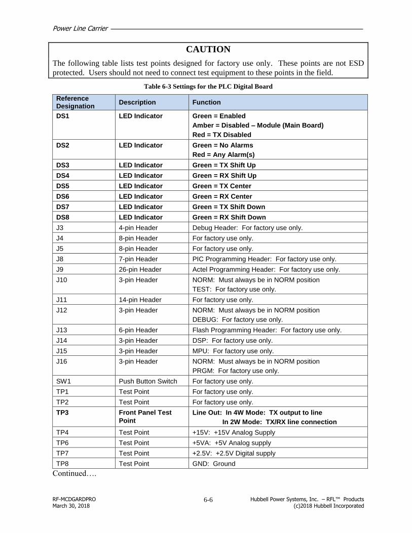
Power Line Carrier
RF-MCDGARDPRO Hubbell Power Systems, Inc. – RFL™ Products March 30, 2018 (c)2018 Hubbell Incorporated
6-6
CAUTION
The following table lists test points designed for factory use only. These points are not ESD
protected. Users should not need to connect test equipment to these points in the field.
Table 6-3 Settings for the PLC Digital Board
Reference Designation
Description Function
DS1 LED Indicator Green = Enabled
Amber = Disabled – Module (Main Board)
Red = TX Disabled
DS2 LED Indicator Green = No Alarms
Red = Any Alarm(s)
DS3 LED Indicator Green = TX Shift Up
DS4 LED Indicator Green = RX Shift Up
DS5 LED Indicator Green = TX Center
DS6 LED Indicator Green = RX Center
DS7 LED Indicator Green = TX Shift Down
DS8 LED Indicator Green = RX Shift Down
J3 4-pin Header Debug Header: For factory use only.
J4 8-pin Header For factory use only.
J5 8-pin Header For factory use only.
J8 7-pin Header PIC Programming Header: For factory use only.
J9 26-pin Header Actel Programming Header: For factory use only.
J10 3-pin Header NORM: Must always be in NORM position
TEST: For factory use only.
J11 14-pin Header For factory use only.
J12 3-pin Header NORM: Must always be in NORM position
DEBUG: For factory use only.
J13 6-pin Header Flash Programming Header: For factory use only.
J14 3-pin Header DSP: For factory use only.
J15 3-pin Header MPU: For factory use only.
J16 3-pin Header NORM: Must always be in NORM position
PRGM: For factory use only.
SW1 Push Button Switch For factory use only.
TP1 Test Point For factory use only.
TP2 Test Point For factory use only.
TP3 Front Panel Test
Point
Line Out: In 4W Mode: TX output to line
In 2W Mode: TX/RX line connection
TP4 Test Point +15V: +15V Analog Supply
TP6 Test Point +5VA: +5V Analog supply
TP7 Test Point +2.5V: +2.5V Digital supply
TP8 Test Point GND: Ground
Continued….

Power Line Carrier
RF-MCDGARDPRO Hubbell Power Systems, Inc. – RFL™ Products March 30, 2018 (c)2018 Hubbell Incorporated
6-7
Reference Designation
Description Function
TP9 Test Point GND: Digital ground
TP10 Test Point GND: Digital ground
TP11 Test Point +3.3VA: 3.3V Analog supply
TP12 Test Point +1.6V: 1.6V DSP supply
TP13 Test Point -5VA: -5V Analog supply
TP14 Test Point +3.3V: +3.3V Digital supply
TP15 Test Point +5VD: +5V Digital supply
TP16 Test Point GNDA: Analog ground
TP17 Test Point GNDA: Analog ground
TP18 Test Point -15V: -15V Analog supply
TP19 Test Point For factory use only.
TP20 Test Point For factory use only.
TP21 Test Point For factory use only.
TP22 Test Point For factory use only.
TP23 Test Point For factory use only.
TP24 Front Panel Test
Point
GNDA: Analog ground
TP25 Front Panel Test
Point
ADC IN: Analog to digital converter input
TP26 Front Panel Test
Point
RX: Receive level after attenuation stage
TP27 Front Panel Test
Point
TX OUT: Input to power amp
6.3.1.4 The PLC Analog Module Components
The PLC Analog Module has extensive jumper and control settings along with test points.
CAUTION
The following information is to be used by qualified personnel only, normally an HPS/RFL
Service Engineer.
The illustrations below show the location of all switches, jumpers and test points on the module
followed by a description of their use.

Power Line Carrier
RF-MCDGARDPRO Hubbell Power Systems, Inc. – RFL™ Products March 30, 2018 (c)2018 Hubbell Incorporated
6-8
J3 J4 J35, 36 TP7 TP10 J30 J31 J34 J33 J32
TP9
F5
F6
J25
J22
J21
TP11
J24
J20
J19
J18
J17
J15
J16
J14J13J12J27J28J10C2R5J9R2J7J8TP4TP5TP8
J11
J5J6 J39*J38* J40*
L4
Figure 6-3. PLC Analog Module Top View
* Jumpers added on revised board

Power Line Carrier
RF-MCDGARDPRO Hubbell Power Systems, Inc. – RFL™ Products March 30, 2018 (c)2018 Hubbell Incorporated
6-9
CA
UT
ION
ST
AT
ICS
EN
SIT
IVER1
3 A
MP
IMP
ED
AD
J
R8
AM
P G
AIN
AD
J
R1
9T
X F
AIL
AD
J
PA
OU
T
RX
IN
FIN
E
CO
AR
SE
TX
/RX
2W
TX
4W
RX
GN
D
+1
5V
-15
VG
ND
CL
I
Connect dummy load
Common test point (black)
RX in test point
(yellow)
Power amp out test
point (red)
Common test point (black)
R13 Amp impedance adjust
R19 Amp TX fail adjust
R8 Amp gain adjust
R46
S1
Figure 6-4. PLC Analog Module Rear Panel View
TP3 TP1 TP6 TP2
Figure 6-5. PLC Power Amp Section

Power Line Carrier
RF-MCDGARDPRO Hubbell Power Systems, Inc. – RFL™ Products March 30, 2018 (c)2018 Hubbell Incorporated
6-10
Table 6-4 Settings for the PLC Analog Module
Reference Designation
Description Function
C2 Trimmer
capacitor
Used for reflected power meter calibration.
F5 Fuse TX protection fuse, 1A, 250V, slow-blow, HPS/RFL Part No. 103473
F6 Fuse RX protection fuse, 1A, 250V, slow-blow, HPS/RFL Part No. 103473
J3 18-pin Header Used to set TX Filter frequency. See Section 5.5.4
J4 12-pin Header Used to set TX Filter frequency. See Section 5.5.4
J5 12-pin Header Used to set TX Filter frequency. See Section 5.5.4
J6 12-pin Header Used to set TX Filter frequency. See Section 5.5.4
J7 18-pin Header Used to set TX Filter frequency. See Section 5.5.4
J8 12-pin Header Used to set TX Filter frequency. See Section 5.5.4
J9 12-pin Header Used to set TX Filter frequency. See Section 5.5.4
J10 12-pin Header Used to set TX Filter frequency. See Section 5.5.4
J11 18-pin Header Used to set TX Filter frequency. See Section 5.5.4
J12 2-pin Header Used to adjust capacitive component of balance network. See Section 6.3.5
J13 2-pin Header Used to adjust capacitive component of balance network. See Section 6.3.5
J14 2-pin Header Used to adjust capacitive component of balance network. See Section 6.3.5
J15 2-pin Header Used to adjust capacitive component of balance network. See Section 6.3.5
J16 2-pin Header Used to adjust inductive component of balance network. See Section 6.3.5
J17 2-pin Header Used to select or bypasses Inductor L4 which is fine adjustment for inductive
component of Balance Network. See Section 6.3.5
Install Jumper J17 to bypass L4.
Do Not Install J17 to select L4.
J18 2-pin Header Used to adjust inductive component of balance network. See Section 6.3.5
J19 2-pin Header Used to adjust inductive component of balance network. See Section 6.3.5
J20 2-pin Header Used to adjust inductive component of balance network. See Section 6.3.5
J21 3-pin Header Used to select 2-wire operation via Skewed Hybrid or 4-wire operation.
2W = 2-wire operation via Skewed Hybrid.
4W = 4-wire operation (Jumper not used on assembly 500930-20)
J22 3-pin Header Used to select 2-wire operation via Skewed Hybrid or 4-wire operation.
2W = 2-wire operation via Skewed Hybrid.
4W = 4-wire operation (Jumper not used on assembly 500930-20)
J23 TX connector BNC Connector
J24 3-pin Header ISOLATE (FSK) = FSK Operation or ON/OFF 4 –wire operation or ON/OFF 2-
wire operation via Skewed Hybrid.
CONNECT (ON/OFF) = On/Off 2-wire operation (shorts TX to RX, do not
install J27 or J28).
J25 3-pin Header Used to select 2-wire operation via Skewed Hybrid or 4-wire operation.
2W = 2-wire operation via Skewed Hybrid.
4W = 4-wire operation (Jumper not used on assembly 500930-20)
Continued….

Power Line Carrier
RF-MCDGARDPRO Hubbell Power Systems, Inc. – RFL™ Products March 30, 2018 (c)2018 Hubbell Incorporated
6-11
Reference Designation
Description Function
J26 Rx connector BNC Connector
J27 2-pin Header Selects 75 Ohm termination with J27 installed and J28 uninstalled.
Max power dissipation is 1 Watts. Do not install with J24 in
CONNECT(ON/OFF) position.
J28 2-pin Header Selects 50 Ohm termination with J28 installed and J27 uninstalled.
Max power dissipation is 2 Watt. Do not install with J24 in
CONNECT(ON/OFF) position.
J30 3-pin Header Selects internal or external power supply via TB1 pins 1, 2 and 3
on PLC Analog Module rear panel.
Set J30 and J31 to INT to select internal power supply.
Set J30 and J31 to EXT to select external power supply.
J31 3-pin Header
J32 2-pin Header Selects one of three modes of CLI (Carrier Level Indicator) output
driver. Connect external meter to TB1 pins 4 and 6 on PLC
Analog Module rear panel.
Selects 0-5V with J32 installed and J33 and J34 uninstalled.
Selects 0-100uA with J33 installed and J32 and J34 uninstalled.
Selects 0-1mA with J34 installed and J32 and J33 uninstalled.
J33 2-pin Header
J34 2-pin Header
J35 3-pin Header Selects Normal operation or Test operation.
Set J35 and J36 to NOR for Normal operation.
Set J35 and J36 to TEST for Test operation. J36 3-pin Header
J38 3-pin Header Used to set TX Filter frequency (new board only). See Section 6.4
J39 3-pin Header Used to set TX Filter frequency (new board only). See Section 6.4
J40 3-pin Header Used to set TX Filter frequency (new board only). See Section 6.4
L4 Inductor Used for fine adjustment of inductive component of balance
network. See Section 6.3.5
R2 Potentiometer Used for reflected power meter calibration.
R5 Potentiometer Used for reflected power meter calibration.
S1 6-position Rotary
Switch
Used for coarse adjustment of resistive component of balance
network. See Section 6.3.5 for hybrid tuning procedure.
R46 Potentiometer Used for fine adjustment of resistive component of balance
network. See Section 6.3.5 for hybrid tuning procedure.
TP1 Test Point Power Amp Input
TP2 Test Point Power Amp Output (U1 pin 1)
TP3 Test Point Power Amp Fail
TP4 Test Point Ground
TP5 Test Point Ground
TP6 Test Point Ground
TP7 Test Point Power Amp Output To TX Filter
TP8 Test Point Input to Tx Filter
TP9 Test Point Positive Power Supply Rail (For factory use only)
TP10 Test Point Negative Power Supply Rail (For factory use only)
TP11 Test Point In 4-wire operation, monitors TX output to the line.
In 2-wire operation, monitors Input to the Skewed Hybrid.

Power Line Carrier
RF-MCDGARDPRO Hubbell Power Systems, Inc. – RFL™ Products March 30, 2018 (c)2018 Hubbell Incorporated
6-12
This page intentionally
left blank

Power Line Carrier
RF-MCDGARDPRO Hubbell Power Systems, Inc. – RFL™ Products March 30, 2018 (c)2018 Hubbell Incorporated
7-1
Software Upgrade Utility Section 7.
7.1 System Firmware Upgrade Overview
The HPS/RFL™ GARD Pro™ system uses an upgrade tool to install a new system firmware.
RFL now provides the ability to have a backup image of the system firmware. The new
firmware will swap the configuration into a standby partition. This greatly lessens the
downtime when upgrading takes place. This also provides the ability to revert back to the
previous firmware.
Advanced Settings Select “Show Advance Settings” to select the following advanced options. Also select
“Advanced Settings” to choose a different IP address.
Advanced Setting Functionality
Upload – Upload new firmware as standby (selected by default)
Swap & Reboot – Make standby version active (selected by default)
Configuration
o Use Current – Use current configuration after swap and reboot (selected by default)
Note:
The Use Current option is only valid when uploading firmware of equal or greater database
versions. The database version is indicated by the second digit in the firmware release number.
Example: GPRO.2.1.0.7432, where the second digit is 1. If the database version is less than
the current firmware this option is not valid and current configuration will not be present after
reboot.
o Use Standby – Use configuration in the standby partition after swap and reboot
o Reset to Default – Reset configuration values to default after swap and reboot

Power Line Carrier
RF-MCDGARDPRO Hubbell Power Systems, Inc. – RFL™ Products March 30, 2018 (c)2018 Hubbell Incorporated
7-2
Note the following:
Always check the Swap and Reboot when performing a firmware upgrade.
If the Upgrade option is checked without the Swap & Reboot checked, only the Standby
version will be updated.
If the reboot box is checked the Interface Unit will automatically reboot at the end of the
upgrade.
WARNING: Damage may occur
Do Not power off PC or Chassis while Upgrade is running.
7.2 The HPS/RFL GARD Pro system Upgrade Tool Installation
7.2.1 System Firmware Updater Tool Setup
1. To "install" the GARD Updater, simply double click the “UpgradeGARD” setup file.

Power Line Carrier
RF-MCDGARDPRO Hubbell Power Systems, Inc. – RFL™ Products March 30, 2018 (c)2018 Hubbell Incorporated
7-3
2. Click Next to continue.
3. Click Next to install to the default folder or Browse to select a different folder.

Power Line Carrier
RF-MCDGARDPRO Hubbell Power Systems, Inc. – RFL™ Products March 30, 2018 (c)2018 Hubbell Incorporated
7-4
4. Select “Finish” to complete the installation

Power Line Carrier
RF-MCDGARDPRO Hubbell Power Systems, Inc. – RFL™ Products March 30, 2018 (c)2018 Hubbell Incorporated
7-5
7.3 The HPS/RFL GARD Pro system Firmware Upgrade Procedure
Upgrade Procedure
Note: Before starting the upgrade follow the Gard Upgrade Tool installation.
1. Double Click the shortcut on the desktop
2. The IP address is preset to 192.168.1.1 to match the front port of the chassis.
3. Open a Browser window to log into the front port of the chassis 192.168.1.1

Power Line Carrier
RF-MCDGARDPRO Hubbell Power Systems, Inc. – RFL™ Products March 30, 2018 (c)2018 Hubbell Incorporated
7-6
4. Enable SCP (for field upgrades) to allow a connection to the front port of the Chassis and
save the changes
5. Make note of the current Controller firmware (Release and Build) in the System
Management/Inventory for later comparison after the upgrade process completes.

Power Line Carrier
RF-MCDGARDPRO Hubbell Power Systems, Inc. – RFL™ Products March 30, 2018 (c)2018 Hubbell Incorporated
7-7
6. Click the Green refresh arrows and the connection state should change from N/A to “OK”
7. Use the Browse button to locate the version Zip file to be used for Upgrade.
8. Select the firmware image Zip file to be used for Upgrade.

Power Line Carrier
RF-MCDGARDPRO Hubbell Power Systems, Inc. – RFL™ Products March 30, 2018 (c)2018 Hubbell Incorporated
7-8
9. Once the file is selected, click the “GARD Upgrade” button to upload the .zip file to the
HPS/RFL GARD Pro system.
10. Wait for reboot. When complete, the progress bar will read 100% complete and reboot
automatically.
Note:
The Reboot Process takes approximately 2 minutes to complete and the error below will appear
when communication is lost.

Power Line Carrier
RF-MCDGARDPRO Hubbell Power Systems, Inc. – RFL™ Products March 30, 2018 (c)2018 Hubbell Incorporated
7-9
11. Log back into the HPS/RFL GARD Pro system after the reboot is complete.
12. Finally, verify the firmware upgrade was successful in the System Management/Inventory
page by comparing the Controller information (Release and Build) with the Release and
Build noted previously.
Power Line Carrier
RF-MCDGARDPRO Hubbell Power Systems, Inc. – RFL™ Products March 30, 2018 (c)2018 Hubbell Incorporated
7-10
This page intentionally
left blank

Technical Data/Specifications
RF-MCDGARDPRO Hubbell Power Systems, Inc. – RFL™ Products March 30, 2018 (c)2018 Hubbell Incorporated
8-1
Technical Data/Specifications Section 8.
As of the date this Instruction Manual was published, the following specifications apply to the
HPS/RFL™ GARD Pro™ system. Because all of HPS/RFL products undergo constant
refinement and improvement, these specifications are subject to change without notice.
8.1 System Specifications
Temperature:
Operating: -20°C to +70°C (-4°F to 158°F)
Storage: -40°C to +85°C (-40°F to 185°F)
Relative Humidity:
Up to 95% at +40°C(+104°F)
8.1.1 Inputs and Outputs
The HPS/RFL GARD Pro system can be configured with up to 20 input and output slots
available on the rear part of the chassis. Relay outputs are jumper selectable Form A or Form
B, and in addition each input and output has an inverter and a timer associated with it that has
settings for both pick-up (de-bounce) delay and drop-out (pulse-stretch) delay.
Optically Isolated Inputs:
Quantity: Six per module.
Jumper selectable Input Voltage: 24/48/125/250Vdc
Rating No Operation Operates Max. Input Voltage
24V <14V >19V 36V
48V <28V >38V 68V
125V <70V >95V 150V
250V <140V >189V 300V
Input Current: Minimum 1.5mA
Minimum Pulse Width 0.03ms, additional de-bounce time set with logic
timer settings.
Solid-State Outputs:
Quantity: Six per module.
Output Current: Max. 1A continuous, 2A for 1 minute, or 10A for
100msec.
Open-Circuit Voltage: 300Vdc max.
Pick-up Time: <1msec.
Continued…..

Technical Data/Specifications
RF-MCDGARDPRO Hubbell Power Systems, Inc. – RFL™ Products March 30, 2018 (c)2018 Hubbell Incorporated
8-2
Relay Outputs:
Quantity: Six per module.
Relay Pick-up Time: 4msec.
Output Current Rating: 6A continuous
Surge: 30A for 200msec.
AlarmRelays:
Quantity: Two
Contacts: SPDT (Form C)
Rating: 100mA, 300Vdc resistive load

Technical Data/Specifications
RF-MCDGARDPRO Hubbell Power Systems, Inc. – RFL™ Products March 30, 2018 (c)2018 Hubbell Incorporated
8-3
8.1.2 The HPS/RFL GARD Pro System Power Supply Specifications
Table 8-1 The HPS/RFL GARD Pro System Power Supply Specifications
Specifications
Power Supply Part Number
500305
500315
500325
Input Voltage Range:
48-125Vdc or 120Vac 200-300Vdc or 220Vac 19-29Vdc
Max Output Current:
+18V -18V
4.00 Amps (combined total)
4.00 Amps (combined total)
4.00 Amps (combined total)
Adjustments:
none
none none
Test Points: TP1 TP2 TP3
+18 Volts nominal
Common -18 Volts nominal
+18 Volts nominal
Common -18 Volts nominal
+18 Volts nominal
Common -18 Volts nominal
Indicators:
DS1 – Normal (Green)
DS1 – Normal (Green) DS1 – Normal (Green)
Fuses: (2) Manufactured Prior to March 2016
4A, 250 V SLO-BLO (3AG ¼ x 1¼)
2A, 250 V SLO-BLO (3AG ¼ x 1¼)
10A, 32 V SLO-BLO
(3AG ¼ x 1¼)
Manufactured after March 2016
4A, 250 V SLO-BLO (5mm x 20mm)
2A, 250 V SLO-BLO (5mm x 20mm)
10A, 32 V SLO-BLO (5mm x 20mm)
Operating Temperature:
-20oC to +70
oC -20
oC to +70
oC -20
oC to +70
oC
Humidity:
95% @ +40oC
95% @ +40
oC
95% @ +40
oC
Isolation:
2500 Vdc isolation from input terminals to ground, and input terminals to output terminals.
2500 Vdc isolation from input terminals to ground, and input terminals to output terminals.
2500 Vdc isolation from input terminals to ground, and input terminals to output terminals.
RFI Susceptibility:
ANSI PC37.90.2 (35 Volts/Meter)
IEC 255-22-3 (RFI Class III)
Interface Dielectric Strength:
All contact inputs, solid-state outputs, power supply inputs and relay outputs meet the following
specifications:
ANSI C37.90-1989 (Dielectric)
ANSI C37.90.1-1989 (SWC and Fast Transient))
EN 60255-5 (1500Vrms Breakdown Voltage and Impulse Withstand)
EN 60255-22-1 (SWC Class III)

Technical Data/Specifications
RF-MCDGARDPRO Hubbell Power Systems, Inc. – RFL™ Products March 30, 2018 (c)2018 Hubbell Incorporated
8-4
EN60255-22-2 (ESD Class III)
EN60255-22-4 (Fast-Transient Class III)
EN60834-1
8.2 Optional Modules
8.2.1 Power Line Carrier Specifications
Modes of Operation: FSK (2F or 3F), On/Off
Number of Active Channels:
3RU One
6RU One to Four
Operating Band: 30Hz to 30kHz
Channel Tuning Resolution: 125Hz
Maximum Transmit Power: 10W
Transmit Output Impedance: 50Ω (75Ω Skewed Hybrid Available)
Maximum Transmitter Accuracy: ±10Hz
Maximum Level of Spurious Emissions: -55dBc
Maximum Receive Input Level: 25Vrms (+41dBm @ 50Ω)
Receive Dynamic Range: >40dB
Maximum Receive Sensitivity: 5mVrms (-33dBm @ 50Ω)
Operating Temperature -20ºC to +70ºC (-4ºF to +158ºF)
Receive Input Impedance:
Terminated 50 - 75Ω selectable
Un-terminated >30k Ω
Insertion Loss (Skewed Hybrid):
Transmit : 0.5dB (nominal)
Receive: -13dB (nominal)
Frequency Response (Output Filter): ±0.5dB over selected frequency band
8.2.2 50W 9508 RF Chassis Specifications (Option)
8.2.2.1 50W Power Amplifier
Number of Inputs: One or two
Input Level: +4dBm @ 75Ω – single input
+1dBm @ 75Ω – two inputs
Input Impedance: 75Ω nominal
Frequency Response: Flat within ±2.0dB from 20kHz to 500kHz
Maximum Output: 50W PEP

Technical Data/Specifications
RF-MCDGARDPRO Hubbell Power Systems, Inc. – RFL™ Products March 30, 2018 (c)2018 Hubbell Incorporated
8-5
Output Impedance: 50Ω nominal
Input Power: +92Vdc @ 2.0A
+30Vdc @ 0.2A
Operating Temperature: -20ºC to +65ºC (-4ºF to +149ºF)
Dimensions:
Height: 5.25in (13.3cm)
Width: 17.625in (44.7cm) with mounting ears 19in (48.2cm)
Depth: 19.5in (49.5cm)
8.2.2.2 Power Amplifier, Power Supply
Input Voltage Range:
Part No. 107250-4: 38Vdc to 150Vdc
Part No. 107250-5: 200Vdc to 300Vdc
Output Power: 30Vdc @ 0.25A
92Vdc @ 2.4A
Operating Temperature: -20ºC to +65ºC (-4ºF to +149ºF)
Humidity: +95% @ +40ºC
Isolation: 2500Vdc isolation from input terminal to ground, output
terminals to ground, input terminals to output terminals,
relay terminals to ground, and relay contacts to coil.
8.2.2.3 Line Board
Power Capability: 100W maximum
Frequency Range:
Part No. 103090: 20 to 500kHz
Impedance:
Transmit Input: 50Ω
Receive Output: 50Ω
Line: Adjustable to 50, 75, 100, or 130Ω
Continued………..
Insertion Loss
Transmit : 0.5dB Maximum
Receive: 14dB typical
Input Power Requirements None; passive components only (no active components)
Operating Temperature: -20ºC to +65ºC (-4ºF to +149ºF)

Technical Data/Specifications
RF-MCDGARDPRO Hubbell Power Systems, Inc. – RFL™ Products March 30, 2018 (c)2018 Hubbell Incorporated
8-6
8.3 DNP3 Device Profile Document
DNP V3.00 DEVICE PROFILE DOCUMENT Vendor Name: Hubbell Power Systems
Device Name: HPS/RFL™ GARD Pro™ system
Highest DNP Level Supported: Device Function:
For Requests Level 3 Master Slave
For Responses Level 3
Notable objects, functions, and/or qualifiers supported in addition to the Highest DNP Levels Supported (the complete list is described in the attached table):
None
Maximum Data Link Frame Size (octets): Maximum Application Fragment Size (octets)
Transmitted 292 Transmitted 2048 (if >2048, must be configurable)
Received (must be 292) 292 Received 2048 (must be > 249)
Maximum Data Link Re-tries: Maximum Application Layer Re-tries:
None None
Fixed at _______________________ Configurable, range ____ to _______
Configurable, range ____ to _______ (Fixed is not permitted)
Requires Data Link Layer Confirmation:
Never
Always
Sometimes If 'Sometimes', when?
Configurable If 'Configurable', how?
Requires Application Layer Confirmation:
Never
Always (not recommended)
When reporting Event Data (Slave devices only)
When sending multi-fragment responses (Slave devices only)
Sometimes If 'Sometimes', when?
Configurable If 'Configurable', how?

Technical Data/Specifications
RF-MCDGARDPRO Hubbell Power Systems, Inc. – RFL™ Products March 30, 2018 (c)2018 Hubbell Incorporated
8-7
Timeouts while waiting for:
Data Link Confirm None Fixed at Variable Configurable
Complete Appl. Fragment None Fixed at Variable Configurable
Application Confirm None Fixed at 5000 ms Variable Configurable
Complete Appl. Response None Fixed at Variable Configurable
Others_____________________________________
Attach explanation if 'Variable' or 'Configurable' was checked for any timeout
Sends/Executes Control Operations:
WRITE Binary Outputs Never Always Sometimes Configurable
SELECT/OPERATE Never Always Sometimes Configurable
DIRECT OPERATE Never Always Sometimes Configurable
DIRECT OPERATE - NO ACK Never Always Sometimes Configurable
Count > 1 Never Always Sometimes Configurable
Pulse On Never Always Sometimes Configurable
Pulse Off Never Always Sometimes Configurable
Latch On Never Always Sometimes Configurable
Latch Off Never Always Sometimes Configurable
Queue Never Always Sometimes Configurable
Clear Queue Never Always Sometimes Configurable
Attach explanation if 'Sometimes' or 'Configurable' was checked for any operation
.FILL OUT THE FOLLOWING ITEMS FOR SLAVE DEVICES ONLY:
Reports Binary Input Change Events when no specific variation requested:
Reports time-tagged Binary Input Change Events when no specific variation requested:
Never Never
Only time-tagged (SOE Triggered only) Binary Input Change With Time (SOE
Triggered only)
Only non-time-tagged (HMI outputs) Binary Input Change With Relative Time
Configurable to send both, one or the other
(attach explanation) Configurable (attach explanation)
Sends Unsolicited Responses: Sends Static Data in Unsolicited Responses:
Never Never
Configurable (attach explanation) When Device Restarts
Only certain objects When Status Flags Change
Sometimes (attach explanation) No other options are permitted
ENABLE/DISABLE UNSOLICITED
Function codes supported

Technical Data/Specifications
RF-MCDGARDPRO Hubbell Power Systems, Inc. – RFL™ Products March 30, 2018 (c)2018 Hubbell Incorporated
8-8
Default Counter Object/Variation: Counters Roll Over at:
No Counters Reported No Counters Reported
Configurable (attach explanation) Configurable (attach explanation)
Default Object 20 16 Bits
Default Variation 1 32 Bits (SOE Counters)
Point-by-point list attached Other Value _8 bits__ (Only for PLC module counters)
Point-by-point list attached
Sends Multi-Fragment Responses: Yes No
This document must be accompanied by a table having the following headings:
Object Group Request Function Codes Response Function Codes
Object Variation Request Qualifiers Response Qualifiers
Object Name (optional)
See the HPS/RFL GARD Pro System Instruction Manual, section 4.16.1.1
8.4 Disposal
When disposing of the equipment, it should be done in strict accordance with all local and
national regulations for the disposal of electrical and electronic equipment. The printed circuit
boards should be separated for recycling.

Index
RF-MCDGARDPRO Hubbell Power Systems, Inc. – RFL™ Products March 30, 2018 (c)2018 Hubbell Incorporated
9-1
Index Section 9.
9.1 Index
9
9508 RF Chassis · 5-49
50W Power Amp · 5-52
50W Power Amp Circuit Board · 5-54
9508 RF Chassis Block Diagram · 5-52
Additional 50W Module in 100W Systems · 5-53
Attenuator Board · 5-69
Settings · 5-69
Balance Board and External Amp Connection Board ·
5-62
Chassis · 5-51
Line Board · 5-64
Setting Jumpers · 5-66
Motherboard · 5-70
Rear Panel Connector Assignments · 5-70
Power Amp Board Jumpers · 5-55
Power Amp Power supply · 5-57
Quick Tuning and Jumper Setting Overview · 5-71
Rear Panel Wiring – HPS/RFL GARD Pro System
with 50W · 5-73
Rear Panel Wiring for the HPS/RFL GARD Pro
System PLC with 100W Applications · 5-74
RX Connection board · 5-68
RX Filter · 5-67
Tuning
RX Filter · 5-68
TX Filter · 5-58
TX Filter Jumpers · 5-58
TX Tuning Procedure · 5-60
A
Access Levels · 4-7
Alarm and Alert Relay Connections · 3-10
Alarm Relay and Input Power Connections · 3-9
Alarm States (Color) · 4-7
Alarms - System · 4-39
Configuration · 4-41
Status · 4-39
B
Boot-Up Sequence · 3-20
C
Carrier Level Indicator · 5-9
Loads · 5-47 Chassis Ground · 3-11
Chassis Grounding · 1-1
CLI Meter Tuning · 5-47
CLI Settings · 5-46
Commissioning and Verification
Calibrations through the User Interface · 5-36
Hybrid Tuning Procedure · 5-39
Rear Module Adjustments · 5-37
Transmit Fail Adjustment · 5-39
Verifying /Adjusting the Transmit Output Power · 5-39
Verifying/Adjusting Amplifier Impedance · 5-38 Configuration
FSK, Advanced · 5-13
FSK, General · 5-11
Logic · 4-49
Logic Timers · 4-50
On-Off, Advanced · 5-24
On-Off, Checkback · 5-27
On-Off, General · 5-22
On-Off, Hard Carrier · 5-30
CONTROLLER CARD BACKGROUND COLOR · 2-13
Current Limiter Option · 3-19
D
DNP3 Device Profile Document · 8-6
Dynamic Menu Feature · 4-20
E
Earth Stud - Location · 1-1
Effectivity · 11
External Labels · 1-4
F
File Operations · 4-11

Index
RF-MCDGARDPRO Hubbell Power Systems, Inc. – RFL™ Products March 30, 2018 (c)2018 Hubbell Incorporated
9-2
Saving Files to a PC · 4-13
Sending files to the RFL™ GARD Pro™ System · 4-
11
Front Panel Indicators · 2-9
FTP Server · 4-15
Function Buttons (PLC) · 5-15
G
GUI · 2-10
H
HPS/RFL GARD Pro System Dashboard · 4-6
I
Input Power Connections · 3-11
Input Unit - Setting Jumpers · 4-23
Input/Output Module · 2-6, 4-21
Input/Output Modules
Input - Test · 4-29
Input Advanced Configuration · 4-28
Input Mapping · 4-27
Output - Advanced Configuration · 4-33
Output - Test · 4-34
Output Mapping · 4-32
Status · 4-24 Installation · 3-1
Interconnected Chassis - Installed in Rack or Cabinet ·
3-4
Interconnected Chassis - Mounted on Shipping Rails ·
3-4
Mounting · 3-2
Individual Chassis · 3-2
Mounting Dimensions · 3-3
Unpacking · 3-1
Individual Chassis · 3-1
Interconnected Chassis · 3-1 Inventory and Version Info · 4-19
Inventory Info · 4-19
IRIG-B through rear RS-232 port · 3-15
L
LEDs Front Panel · 4-36
Configuration · 4-37
Status · 4-36
N
Network Application · 2-9
O
Ordering Information · 12
P
Part Numbers
Analog Module Assembly · 5-44, 5-45
PLC
FSK · 5-1
FSK - Min. Channel Spacing · 5-3
Function · 5-1
On/Off Block - Transport Delay and Channel Spacing ·
5-5
On/Off Operation · 5-4
Trip Transport Delay and Channel Spacing · 5-2 PLC Calibration
TX Level Calibration · 5-34 PLC Module · 5-9
Power Supply Specifications · 8-3
R
Rear Connections
Analog PLC Module · 5-7
Second PLC Module · 5-77 Receiver Operating Range and Dynamic Range · 5-34
Relay Output Unit - Setting Jumpers · 4-24
Revision Record · 11
RF Chassis Specifications · 8-4
RFL™ GARD Pro™ System Slot Location and Module Description · 2-3
S
Safety Instructions · 1-1
Safety Summery · 1-1 Second PLC Module - Jumper Settings · 5-78
Settings - General Information · 4-21
Settings Recommended
Checkback – 2-Terminal · 5-28
Checkback – 3-Terminal · 5-29
Hard Carrier – 2-Terminal · 5-31
Hard Carrier – 3-Terminal · 5-32
PLC FSK · 5-16
PLC On-Off · 5-25 Single On-Off Switch · 5-75
Slot Locations (3U) · 2-3
Slot Locations (6U) · 2-4
SOE · 4-43
Record Details · 4-44
Retrieving · 4-43
SOEs
Configuration · 4-48
Record Details (Logic Bits) · 4-45 Status
Index
RF-MCDGARDPRO Hubbell Power Systems, Inc. – RFL™ Products March 30, 2018 (c)2018 Hubbell Incorporated
9-3
FSK · 5-9
On-Off · 5-20 Supplied Drawings · 2-2
Switched Battery Power Supply · 5-75
System Configuration · 4-1
Connecting a Laptop and setting IP Addresses · 4-1 System Description
Key Features · 2-1
System Modules and Options Listing · 2-2
System Settings · 4-51
Clock · 4-52
System Specifications · 8-1
T
Table of Contents · 3
Technical Data - Specifications · 8-1
PLC · 8-4 Test
FSK · 5-18
On-Off · 5-33 Transmit Carrier Frequency Range · 5-43
Troubleshooting · 6-1
Connectivity Issues · 6-1
Module Level Alarms
PLC Digital Module · 6-3
PLC Board Analog · 6-8
PLC Board Digital · 6-5
PLC Issues · 6-4 TSD · 2-15
PUSH BUTTON INTERFACE · 4-58
SCREEN DISPLAY · 4-56
SCREEN INITIALIZATION · 2-17
Screen Orientation · 2-16 TX Carrier Frequency - Jumper Settings · 5-44, 5-45
U
User Administration · 4-7
Access Control · 4-9
Access Log · 4-10
V
Ventilation · 3-4

Index
RF-MCDGARDPRO Hubbell Power Systems, Inc. – RFL™ Products March 30, 2018 (c)2018 Hubbell Incorporated
9-4
This page intentionally
left blank

Index
RF-MCDGARDPRO Hubbell Power Systems, Inc. – RFL™ Products March 30, 2018 (c)2018 Hubbell Incorporated
10-5
Application Notes Section 10.
This section contains application notes, which are intended to assist the user in configuring their
HPS/RFL™ GARD Pro™ system.
Currently there are no Application Notes for this product.

RFL™ GARD Pro™ System Hubbell Power Systems, Inc. – RFL™ Products
March 30, 2018 (c)2018 Hubbell Incorporated
Hubbell Power Systems, Inc. – RFL™ Products 353 Powerville Road Boonton Twp., NJ 07005-9151 USA Tel: 973.334.3100 Fax: 973.334.3863 Email: [email protected] www.rflelect.com