HPE Synergy 12000 Frame Setup and Installation …...These symbols, on power supplies or systems,...
121
HPE Synergy 12000 Frame Setup and Installation Guide Part Number: 806424-005 Published: September 2019 Edition: 5 Abstract This document describes identification, installation, and setup for the HPE Synergy System. This guide is for an experienced service technician. Hewlett Packard Enterprise assumes you are qualified in the servicing of the HPE Synergy components and overall solution.
Transcript of HPE Synergy 12000 Frame Setup and Installation …...These symbols, on power supplies or systems,...

HPE Synergy 12000 Frame Setup andInstallation Guide
Part Number: 806424-005Published: September 2019Edition: 5
Abstract
This document describes identification, installation, and setup for the HPE Synergy System. This guide is foran experienced service technician. Hewlett Packard Enterprise assumes you are qualified in the servicing ofthe HPE Synergy components and overall solution.

© Copyright 2016-2019 Hewlett Packard Enterprise Development LP
Notices
The information contained herein is subject to change without notice. The only warranties for Hewlett Packard Enterpriseproducts and services are set forth in the express warranty statements accompanying such products and services.Nothing herein should be construed as constituting an additional warranty. Hewlett Packard Enterprise shall not be liablefor technical or editorial errors or omissions contained herein.
Confidential computer software. Valid license from Hewlett Packard Enterprise required for possession, use, or copying.Consistent with FAR 12.211 and 12.212, Commercial Computer Software, Computer Software Documentation, andTechnical Data for Commercial Items are licensed to the U.S. Government under vendor's standard commercial license.
Links to third-party websites take you outside the Hewlett Packard Enterprise website. Hewlett Packard Enterprise has nocontrol over and is not responsible for information outside the Hewlett Packard Enterprise website.
Acknowledgments
Microsoft® and Windows® are either registered trademarks or trademarks of Microsoft Corporation in the United Statesand/or other countries.

Contents
Planning the installation.................................................................................................. 6Safety and regulatory compliance......................................................................................................................................................................... 6Site requirements.............................................................................................................................................................................................................6Warning, caution, and important messages..................................................................................................................................................... 6Determine power and cooling configurations.................................................................................................................................................7
Power supply calculations.........................................................................................................................................................................7Power requirements......................................................................................................................................................................................7
Space and airflow requirements..............................................................................................................................................................................8Temperature requirements........................................................................................................................................................................................8Grounding requirements............................................................................................................................................................................................. 9Supported racks and rack options......................................................................................................................................................................... 9
Rack-free environment requirements................................................................................................................................................ 9HPE Synergy configuration.................................................................................................................................................................................... 10Pallet contents................................................................................................................................................................................................................10
Component and LED identification.............................................................................. 13Information pull tabs...................................................................................................................................................................................................13
Mobile-ready content................................................................................................................................................................................14Mobile QR code locations....................................................................................................................................................................... 14
Frame front components and device bays.....................................................................................................................................................14Device bay numbering..............................................................................................................................................................................15Front panel components......................................................................................................................................................................... 17Appliance module LEDs and components....................................................................................................................................18Compute module LEDs and buttons................................................................................................................................................21Storage module LEDs............................................................................................................................................................................... 23
Frame rear components............................................................................................................................................................................................24Rear component bay numbering........................................................................................................................................................25HPE Synergy 4-Port Frame Link Module components and LEDs.................................................................................. 26HPE Synergy Frame Link Module components and LEDs.................................................................................................. 29Power supply LED.......................................................................................................................................................................................31Fan LED.............................................................................................................................................................................................................31HPE Synergy 10Gb Interconnect Link Module LEDs and buttons................................................................................ 32HPE Synergy 10Gb Interconnect Module interconnect link port................................................................................... 32HPE Synergy 20Gb Interconnect Link Module LEDs and buttons................................................................................ 33HPE Synergy 20Gb Interconnect Link Module interconnect link ports...................................................................... 34HPE Synergy 50Gb Interconnect Link Module LEDs and buttons................................................................................ 34HPE Synergy 50Gb Interconnect Link Module interconnect link ports...................................................................... 35HPE Virtual Connect SE 100Gb F8 Module for HPE Synergy LEDs and buttons................................................ 35HPE Virtual Connect SE 100Gb F32 Module for HPE Synergy components..........................................................39HPE Virtual Connect SE 40Gb F8 Module for HPE Synergy LEDs and buttons................................................... 39HPE Virtual Connect SE 40Gb F8 Module for HPE Synergy components................................................................ 41HPE Synergy 40Gb F8 Switch Module LEDs and buttons..................................................................................................42HPE Synergy 40Gb F8 Switch Module components.............................................................................................................. 44Mellanox SH2200 Switch Module for HPE Synergy LEDs and components........................................................... 45
Installation........................................................................................................................46Installing the Synergy system components.................................................................................................................................................. 46Removing components from the frame ..........................................................................................................................................................46
3

Installing the frame in a rack-free environment..........................................................................................................................................47Installing the frame in a rack..................................................................................................................................................................................47
Measuring with the rack template.....................................................................................................................................................48Installing the rack rails for a square-hole rack........................................................................................................................... 48Installing the rack rails for a round-hole rack............................................................................................................................. 50Installing the frame into the rack ......................................................................................................................................................51
Component installation............................................................................................................................................................................................. 54Installing an appliance module............................................................................................................................................................54Configuring the device bays................................................................................................................................................................. 55Installing compute modules .................................................................................................................................................................61Installing a frame link module .............................................................................................................................................................65Installing the storage module...............................................................................................................................................................66Installing drives in the storage module.......................................................................................................................................... 67Installing fans.................................................................................................................................................................................................68Installing interconnect modules..........................................................................................................................................................69Installing power supplies.........................................................................................................................................................................76Installing a DC power supply................................................................................................................................................................ 79
Cabling the frame......................................................................................................................................................................................................... 84
HPE Synergy Cabling......................................................................................................86
Configuring HPE Synergy.............................................................................................. 87Configuration overview............................................................................................................................................................................................. 87
HPE Synergy Console connections...................................................................................................................................................88Run hardware setup...................................................................................................................................................................................93Remotely connect to HPE OneView.................................................................................................................................................94Configure Network Time Protocol.....................................................................................................................................................94Add IP and subnet address ranges...................................................................................................................................................94Configure the hardware in HPE OneView.....................................................................................................................................94Update the firmware..................................................................................................................................................................................96Configure HPE Synergy Image Streamer......................................................................................................................................96Configure additional settings...............................................................................................................................................................97
Troubleshooting.............................................................................................................. 98Symbols on equipment..............................................................................................................................................................................................98Error screens when connecting to the HPE Synergy Console............................................................................................................98
HPE Synergy Console not responding............................................................................................................................................98Frame not claimed by an HPE Synergy Console....................................................................................................................100The HPE Synergy Console cannot connect to HPE OneView........................................................................................100HPE Synergy Console icons............................................................................................................................................................... 101
Issues during installation.......................................................................................................................................................................................105HPE Synergy Console..............................................................................................................................................................................................106
Accessing the HPE OneView Maintenance Console from the frame link module..............................................107Connecting to the HPE OneView maintenance console using SSH............................................................................107Creating a support dump file.............................................................................................................................................................107
Resetting to factory settings.............................................................................................................................................................................. 108Resetting the appliance module to the original factory settings.................................................................................108Frame link module factory reset......................................................................................................................................................110Performing a frame link module factory reset........................................................................................................................ 111
HPE Synergy documentation resources................................................................... 112HPE Synergy firmware update resources....................................................................................................................................................113
4

HPE Synergy document overview (documentation map)..................................... 115
Specifications.................................................................................................................116HPE Synergy QuickSpecs......................................................................................................................................................................................116
Electrostatic discharge.................................................................................................117
Support and other resources...................................................................................... 118Accessing Hewlett Packard Enterprise Support......................................................................................................................................118Accessing updates.................................................................................................................................................................................................... 118Customer self repair.................................................................................................................................................................................................119Remote support.......................................................................................................................................................................................................... 119Warranty information.............................................................................................................................................................................................. 119Regulatory information.......................................................................................................................................................................................... 120Documentation feedback...................................................................................................................................................................................... 120
Acronyms and abbreviations......................................................................................121
5
Planning the installation
Safety and regulatory complianceFor important safety, environmental, and regulatory information, see Safety and Compliance Information for Server,Storage, Power, Networking, and Rack Products, available at the Hewlett Packard Enterprise website (http://www.hpe.com/support/Safety-Compliance-EnterpriseProducts).
Site requirementsSelect an installation site that meets the detailed installation site requirements described in the site planning guide on theHewlett Packard Enterprise website (http://www.hpe.com/info/synergy-docs).
Warning, caution, and important messages
WARNING: To reduce the risk of personal injury or damage to equipment, heed all warnings and cautionsthroughout the installation instructions.
WARNING: To reduce the risk of personal injury or damage to the equipment, be sure that:
• The leveling feet are extended to the floor.
• The full weight of the rack rests on the leveling feet.
• The stabilizing feet are attached to the rack if it is a single-rack installation.
• The racks are coupled together in multiple-rack installations.
• Only one component is extended at a time. A rack may become unstable if more than one component isextended for any reason.
WARNING: The frame is very heavy. To reduce the risk of personal injury or damage to the equipment:
• Observe local occupational health and safety requirements and guidelines for manual material handling.
• Remove all installed components from the frame before installing or moving the frame.
• Use caution and get help to lift and stabilize the frame during installation or removal, especially when the frameis not fastened to the rack.
WARNING: When lifting the frame with the optional removable handles, always use at least four people to lift theframe into the rack. If the frame is being loaded into the rack above chest level, a fifth person must assist withaligning the frame with the rails while the other four people support the weight of the frame. If you are using amechanical lift to install the frame, two people are required to install the frame into the rack.
WARNING: Install the frame starting from the bottom of the rack and work your way up the rack.
6 Planning the installation

These symbols, on power supplies or systems, indicate that the equipment is supplied by multiplesources of power.
NOTE: To reduce the risk of injury from electric shock, remove all power cords to completelydisconnect power from the system.
• Each frame has two or more power supply cords. A single rack or cabinet may contain morethan one frame. Power may be supplied in a redundant fashion. Removing any single source ofpower does not necessarily remove power from any portion of the system. When performingany service other than hot-plug module replacement, you must completely disconnect allpower to that portion of the system.
• When performing service procedures on frames, shut off the circuit breakers to both A and BAC power feeds and then disconnect all power cords from the outlets before servicing.
WARNING: To reduce the risk of electric shock or damage to the equipment, enter a frame or perform service onsystem components only as instructed in the user documentation.
WARNING: A risk of electric shock from high leakage current exists. Before connecting the AC supply to the powerenclosure, be sure that the electrical outlets are properly grounded (earthed).
CAUTION: Always be sure that equipment is properly grounded and that you follow proper grounding proceduresbefore beginning any installation procedure. Improper grounding can result in ESD damage to electroniccomponents. For more information, see "Electrostatic discharge."
CAUTION: Protect the storage module from power fluctuations and temporary interruptions with a regulating UPS.This device protects the hardware from damage caused by power surges and voltage spikes and keeps the storagemodule in operation during a power failure.
Determine power and cooling configurationsValidate power and cooling requirements based on location and installed components.
For more information, see the HPE Synergy Configuration and Compatibility Guide on the Hewlett Packard Enterprisewebsite (http://www.hpe.com/info/synergy-docs).
Power supply calculationsFor hot-plug power supply specifications, see the HPE Synergy QuickSpecs on the Hewlett Packard Enterprise website(http://www.hpe.com/info/synergy-docs). There is also the Synergy Planning Tool for download. The Synergy PlanningTool helps plan and organize all Synergy options to build a single frame, multiple frame, or racks for a complete solutionready to order from HPE using a simple BOM from the tool. The Synergy Planning Tool can be found on the HewlettPackard Enterprise Sales Portal website in the Tools section.
Power requirementsInstallation of this equipment must comply with local and regional electrical regulations governing the installation of ITequipment by licensed electricians. This equipment is designed to operate in installations covered by NFPA 70, 1999Edition (National Electric Code) and NFPA-75, 1992 (code for Protection of Electronic Computer/Data ProcessingEquipment). For electrical power ratings on options, refer to the product rating label or the user documentation suppliedwith that option.
Planning the installation 7

WARNING: To reduce the risk of personal injury, fire, or damage to the equipment, do not overload the AC supplybranch circuit that provides power to the rack. Consult the electrical authority having jurisdiction over wiring andinstallation requirements of your facility.
CAUTION: Protect the storage module from power fluctuations and temporary interruptions with a regulating UPS.This device protects the hardware from damage caused by power surges and voltage spikes and keeps the storagemodule in operation during a power failure.
Space and airflow requirements
CAUTION: In high-density configurations, the HPE 11000 G2 Series Rack Airflow Optimization Kit (BW930A) mustbe installed to prevent airflow from the rear of the rack to the front the rack through gaps in the rack frame.
To enable servicing and ensure adequate airflow, observe the following spatial requirements when deciding where toinstall a Hewlett Packard Enterprise-branded, Compaq-branded, Telco, or third-party rack:
• Leave a minimum clearance of 63.5 cm (25.0 in) in front of the rack.
• Leave a minimum clearance of 76.2 cm (30.0 in) in back of the rack.
• Leave a minimum clearance of 121.9 cm (48.0 in) from the back of the rack to the rear of another rack or row of racks.
Compute modules draw cool air in through the front and expel warm air through the rear of the frame. Therefore, the frontof the frame must be adequately ventilated to enable ambient room air to enter the frame, and the rear of the frame mustbe adequately ventilated to enable the warm air to escape from the frame.
Hewlett Packard Enterprise Advanced Series Racks, Hewlett Packard Enterprise Series Racks, and Hewlett PackardEnterprise Standard Series Racks provide proper compute module cooling through flow-through perforations in the frontand rear doors that provide 65 percent open area for ventilation.
If the front of the rack is not filled with components, the remaining gaps between the components can cause changes inthe airflow, which can adversely affect cooling within the rack. Cover these gaps with blanking panels.
IMPORTANT: Do not block the ventilation openings.
CAUTION: Always use blanking panels to fill empty vertical spaces in the rack. This arrangement ensures properairflow. Using a rack without blanking panels results in improper cooling that can lead to thermal damage.
Temperature requirementsTo ensure continued safe and reliable equipment operation, install or position the rack in a well-ventilated, climate-controlled environment.
The operating temperature inside the rack is always higher than the room temperature and is dependent on theconfiguration of equipment in the rack. Check the TMRA for each piece of equipment before installation.
CAUTION: To reduce the risk of damage to the equipment when installing third-party options:
• Do not permit optional equipment to impede airflow around the frame or to increase the internal racktemperature beyond the maximum allowable limits.
• Do not exceed the manufacturer’s TMRA.
8 Planning the installation

Grounding requirementsThis equipment must be grounded properly for proper operation and safety. In the United States, you must install theequipment in accordance with NFPA 70, 1999 Edition (National Electric Code), Article 250, as well as any local andregional building codes.
In Canada, you must install the equipment in accordance with Canadian Standards Association, CSA C22.1, CanadianElectrical Code.
In all other countries, you must install the equipment in accordance with any regional or national electrical wiring codes,such as the International Electrotechnical Commission (IEC) Code 364, parts 1 through 7. Furthermore, you must be surethat all power distribution devices used in the installation, such as branch wiring and receptacles, are listed or certifiedgrounding-type devices.
Because of the high ground-leakage currents associated with this equipment, Hewlett Packard Enterprise recommendsthe use of a PDU that is either permanently wired to the building’s branch circuit or includes a nondetachable cord that iswired to an industrial-style plug. NEMA locking-style plugs or those complying with IEC 60309 are considered suitable forthis purpose. Using common power outlet strips to supply power to this equipment is not recommended.
Supported racks and rack optionsThe frame and support rails are engineered for mounting into a 19 in (48.26 cm) wide front panel, 4-post cabinets, andracks that have been designed according to the EIA-310-D standard.
Hewlett Packard Enterprise rails are not compatible with tapped holes. There are two types of supported rail sets for theframe:
• A set for square-hole front and rear mounting flanges
• A set for round-hole flanges
The rails are compatible with a nominal rack-mounting depth of 29 1/8 in (73.98 cm), with an adjustability range of plus½ in (1.27 cm) to minus 1 ½ in (3.81 cm). The rails will work in both a 42.32 in (1075 mm) and a 47.24 in (1200 mm)deep rack.
A 42U/47U rack supports up to four frames.
While the square-hole rail set is the standard option, either rail set supports a fully loaded frame weighing 550 lb (249.48kg). Four of these frames together approach the 2,250 lb (1247.38 kg) internal IT equipment limit of both the HPE 42U x600 mm x 1075 mm and the 42U 600 mm x 1200 mm 11000G2 Series QS racks.
NOTE: The HPE Synergy 12000 Frame is deeper than the c7000 enclosure by approximately 3.5 in (8.89 cm). 42.32 in(1075 mm) racks with side-facing PDUs might interfere with the frame. Hewlett Packard Enterprise recommends using47.24 in (1200 mm) racks.
Cables, PDUs, and other cable management hardware could increase the weight sufficiently to require the use of the HPE42U x 600 mm x 1200 mm Intelligent Series QS rack, which supports 2,750 lb (1247.38 kg) internal IT equipment.
Rack-free environment requirementsThe HPE Synergy 12000 Frame (referred to as the frame) can be used in a rack-free environment. The followingconditions must be met when performing a rack-free installation:
• A fully-populated frame can weigh up to 249.50 kg ( 550.00 lb). The object supporting the frame must be able towithstand this weight.
• Always place the frame on a sturdy, flat surface.
Planning the installation 9
WARNING: To reduce the risk of personal injury or damage to the equipment in a rack-free environment:
◦ Never stack the frame on top of another frame.
◦ Never place equipment on top of the frame.
◦ Never place the frame on a surface that cannot support up to 249.50 kg ( 550.00 lb).
HPE Synergy configurationAn initial setup for HPE Synergy requires software release planning and planning the location for each component. Toensure a proper configuration, review the information in the following documents on the Hewlett Packard Enterprisewebsite (http://www.hpe.com/info/synergy-docs):
• HPE Synergy Configuration and Compatibility Guide—This document helps to understand more about eachcomponent and the configuration requirements for installing each component. It provides the following:
◦ An overview of HPE Synergy management and fabric architecture
◦ Detailed hardware component identification
◦ Hardware configuration guidelines
◦ Interconnect, power, and HPE Synergy Console cabling information
• HPE Synergy Cabling Guide—This document provides detailed information and diagrams on how to cable HPESynergy.
• HPE Synergy Migration Guide—This document takes you through the steps to migrate to the latest offerings ofappliances and Frame Link Modules.
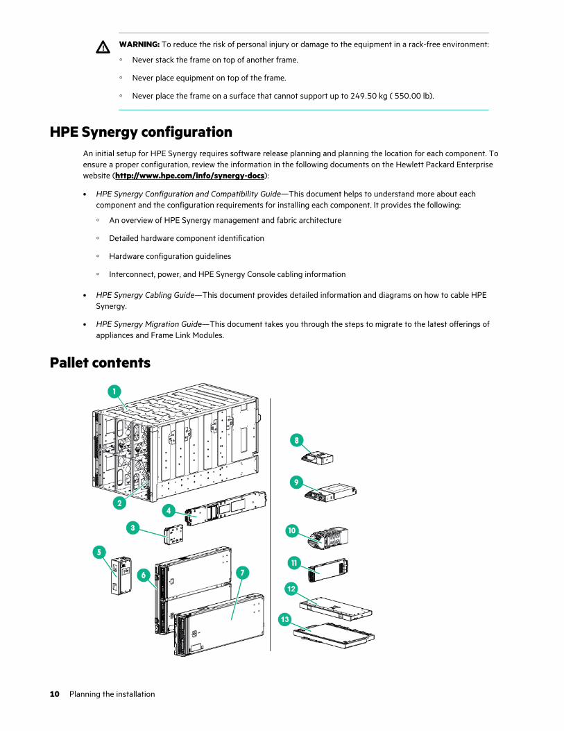
Pallet contents
10 Planning the installation
Item Name Description
1 HPE Synergy 12000 FrameThe frame for installing HPE Synergycomponents.
2 Front panelThe front panel ports of the frame for KVMconnection.
3 Appliance module blankA mandatory insert installed in any unusedappliance module bay.
4 Appliance module1A hardware appliance for embeddedmanagement.
5 Compute module blankA mandatory insert installed in any unusedcompute module bay.
6 Full-height module1The full-height compute module.
7 Half-height module1The half-height compute module.
8 Power supply blankA mandatory insert installed in any unusedpower supply bay.
9 Hot-plug power supply1The power supply for the frame.
10 FanA fan used to cool the components installedin the frame.
11 Frame link module1The frame link module auto-discoversresources in the frame, has a redundantoption, and provides links for scaling offrames.
12 Interconnect blankA mandatory insert installed in any unusedinterconnect bay.
13 Interconnect module2Any of several fabric or networkingcomponents, such as switches orinterconnect link modules, that enablenetworking communication.
14 Lift handles (optional)3The lift handles can be used to lift a frameinto or out of a rack.
15 Removable device bay shelves3The removable device bay shelves can beused to partition the device bays for full orhalf-height components.
Table Continued
Planning the installation 11
Item Name Description
16 Reusable zip ties for power supplies (single-phaseframes only)3 Reusable zip ties that help prevent single-
phase power cables from disconnecting fromthe power connectors.
17 CAT6A cable or DAC cable or SFP+ DAC cable1, 3CAT6A or DAC cable or SFP+ cable forcabling frames, depending on the frame linkmodule ordered.
• 2.00 ft (60.96 cm) cable—Used forcabling two consecutive frames.
• 10.00 ft (304.80 cm) cable—Used forcabling the top frame to the bottomframe in a rack.
• 21.00 ft (640.08 cm) cable—Used forcabling management links requiring longruns to the top of the rack.
18 HPE Synergy Start Here Poster3The quick setup poster provides an overviewof the installation process.
19 Installation instructions for compute modules, options,and interconnects3 The printed installation instructions for HPE
Synergy components.
20 HPE Synergy 12000 Frame Rack Template3The printed template for locating thepositions of frames, rack rails, and cage nutsin a rack.
1 Quantity as ordered2 Quantity and type as ordered3 Not shown
12 Planning the installation

Component and LED identification
Information pull tabsPull tabs on the HPE Synergy frame front and rear provide system information.
Figure 1: Information pull tab locations
Item Description
1 The front pull tab (top left) has the frame product ID, serial number, and the device bay numberingfor the frame front bays.
2 The rear pull tab (top left) has the bay numbering for the frame rear bays.
3 The serial label pull tab is on each compute module and provides the following information:
• Product serial number
• iLO information
• QR code that points to mobile-friendly documentation
Component and LED identification 13

Figure 2: Accessing the information pull tabs
Mobile-ready contentThe HPE Synergy 12000 Frame includes QR codes that point directly to the mobile-ready documentation from yourmobile device.
To access the mobile-ready content, such as setup, installation, user, or troubleshooting documentation, use your mobiledevice to scan the product-specific QR code.
Mobile QR code locationsMobile QR codes are located on HPE Synergy components and pull tabs and provide quick and efficient access to productspecific content for the component. The QR codes takes you to a page that allows you to browse to the onlinedocumentation by choosing an HPE Synergy component.
Frame front components and device bays
14 Component and LED identification

Item Description
1 Device bays—Compute modules and storage modules.
2 Front panel—Provides access to the HPE Synergy Console, through KVM or laptop.
3 Appliance bays.
Device bay numberingAll device bays in the frame are numbered in consecutive order from lowest to highest, from left to right from top tobottom, as observed by a user looking directly at the frame.
Devices larger than half-height (multi-bay devices) are numbered according to the lowest device bay number that themulti-bay device occupies.
For an even number of device modules, they must be installed next to each other between sets of vertical partitions if alldevice bays in the frame are to be used.
For an odd number of single-wide full-height device modules, an even number must be installed next to each otherbetween each vertical partition, and the odd module must be installed in device bay 2 if all device bays in the frame are tobe used.
The device bay numbering is available on the Information pull tabs.
Device bay type Device bay numbering
Single-wide, full-height
Single-wide, half-height
Single-wide, mixed-height
Double-wide, full-height
Double-wide, half-height
Double-wide, mixed-height
Component and LED identification 15
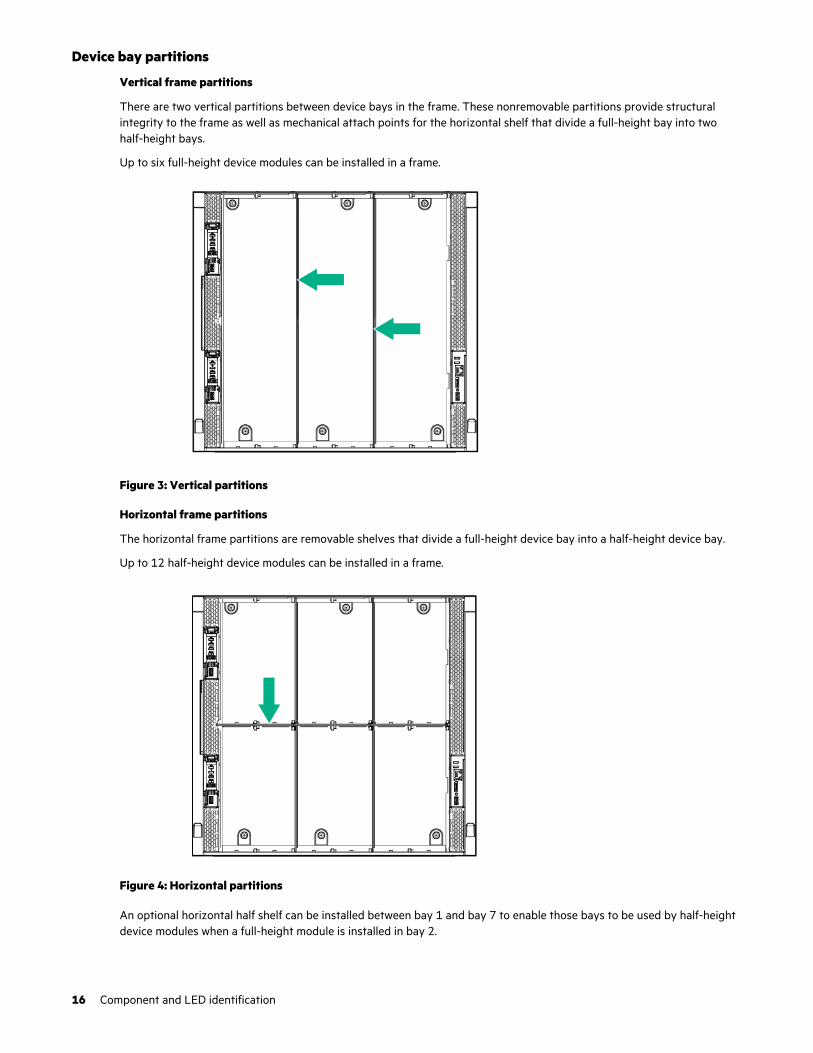
Device bay partitions
Vertical frame partitions
There are two vertical partitions between device bays in the frame. These nonremovable partitions provide structuralintegrity to the frame as well as mechanical attach points for the horizontal shelf that divide a full-height bay into twohalf-height bays.
Up to six full-height device modules can be installed in a frame.
Figure 3: Vertical partitions
Horizontal frame partitions
The horizontal frame partitions are removable shelves that divide a full-height device bay into a half-height device bay.
Up to 12 half-height device modules can be installed in a frame.
Figure 4: Horizontal partitions
An optional horizontal half shelf can be installed between bay 1 and bay 7 to enable those bays to be used by half-heightdevice modules when a full-height module is installed in bay 2.
16 Component and LED identification
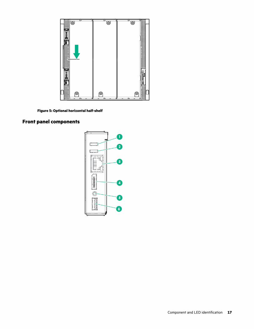
Figure 5: Optional horizontal half-shelf
Front panel components
Component and LED identification 17
Item Description Function
1 UID button Toggles the frame UID on or off.
2 Frame Health LED Indicates the highest severity health status of all components within theframe.
• Solid green—Normal operation
• Flashing amber—Warning
• Flashing red—Critical error
To resolve critical errors and warnings, connect to HPE OneView or to theHPE Synergy Console.
3 Laptop port Provides single laptop access to the frame link module using an RJ-45Ethernet 100BASE-TX connection.
4 Monitor port Provides connectivity for a monitor or an active monitor port adapter toaccess the HPE Synergy Console.
5 Reset button Provides two functions:
• Resets the Active frame link module - momentary press.
• Factory resets both frame link modules - press and hold until UID LEDflashes blue.
NOTE: The reset button does not reset any other component in theframe.
6 USB Provides a connection for supported USB devices such as a keyboard ormouse for HPE Synergy Console use. To connect multiple devices, a USBhub (not included) is required.
Appliance module LEDs and componentsAppliance module LEDs and components are the same for both an HPE Synergy Composer (1st gen) and an HPE SynergyImage Streamer. HPE Synergy Composer2 looks slightly different but has the same LED and components on the frontpanel.
18 Component and LED identification

Figure 6: HPE Synergy Composer (1st gen) and an HPE Synergy Image Streamer (left) and HPE Synergy Composer2(right)
Item Description Function
1 UID LED • Solid blue — Illuminates to locate the appliance module.
• Flashing blue — Indicates appliance module firmware update. Do notpower off or remove appliance module when the UID LED is flashing.
2 Health LED Indicates the health of the appliance module.
• Solid green — Normal operation
• Flashing amber — Warning
• Flashing red — Critical error
The Health LED provides health status of the appliance module. If theHealth LED indicates a warning or a critical error, connect to the HPESynergy Console to troubleshoot.
3 Activity LED Indicates which appliance module is active.
• Off — Indicates that the appliance module is the standby in a HighlyAvailable configuration or HPE OneView is in an error state.
• Solid green — Indicates that the appliance module is active.
• Flashing green — Indicates that the reset button has been pressedand held for greater than 10 seconds, which initiates a reimaging ofthe appliance module. The active LED does not continue to flashgreen during the reimaging process.
Table Continued
Component and LED identification 19
Item Description Function
4 Power LED Indicates power to the appliance module.
• Off — No power. Verify that the appliance module is fully insertedinto the frame link module.
• Flashing amber — The appliance module is initializing.
• Solid amber — The appliance module is powered off.
• Solid green — The appliance module is powered on.
5 Reset button Using an applicator such as a paper clip, press the recessed button toreset the appliance module.
• Press and release — Resets the appliance module.
• Press and hold until activity LED is flashing green — Initiatesreimaging of the appliance module from files on the USB flash driveplugged into the appliance module.
6 USB port USB 2.0/3.0 port for connecting a USB drive to flash a USB recoveryimage.
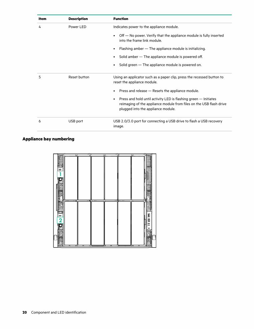
Appliance bay numbering
20 Component and LED identification

Compute module LEDs and buttons
Item Description Status
1 UID LEDSolid blue = Activated
Flashing blue (1 Hz/cycle per sec) =Remote management or firmwareupgrade in progress
Off = Deactivated
2 Health status LEDSolid green = Normal
Flashing green (1 Hz/cycle per sec) =HPE iLO is rebooting
Flashing amber = System degraded
Flashing red (1 Hz/cycle per sec) =System critical
3 Mezzanine NIC status LEDSolid green= Link on any MezzanineNIC
Flashing green= Activity on anyMezzanine NIC
Off = No link or activity on anyMezzanine NIC
4 Power On/Standby button and systempower LED
Solid green = System on
Flashing green (1 Hz/cycle per sec) =Performing power on sequence
Solid amber = System in standby
Off = No power present1
Component and LED identification 21
1 If all other LEDs are off, then no power is present to the compute module. If the health LED is flashing green while the system powerLED is off indicates that the Power On/Standby button service is initializing or that an iLO reboot is in progress. Facility power is notpresent, power cord is not attached, no power supplies are installed, power supply failure has occurred, or the power button cable isdisconnected.
System power LED definitions
The system power LED is located on the compute module Power On/Standby button.
System power LED Definition
Off No power present
Solid amber System is in standby
Flashing green (1 Hz/cycle per sec) Performing power on sequence
Solid green System on
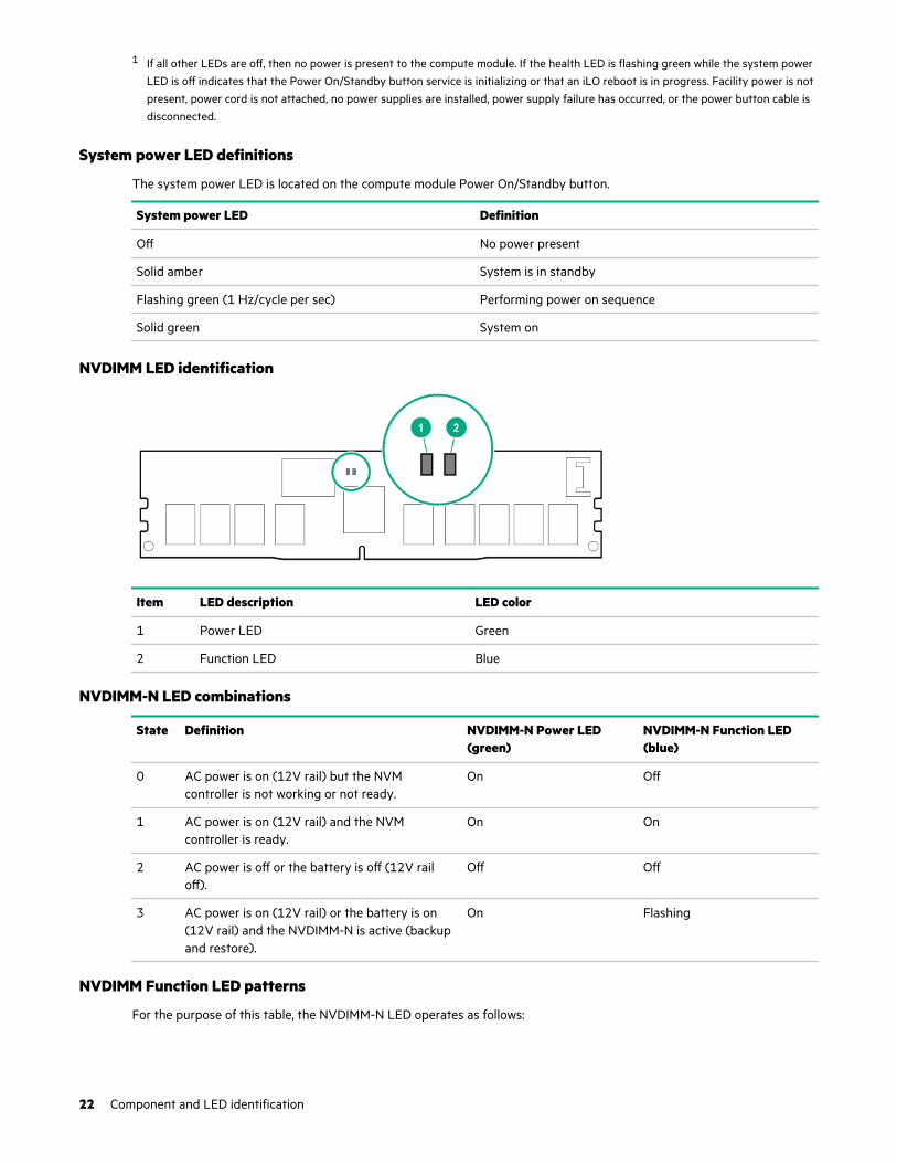
NVDIMM LED identification
Item LED description LED color
1 Power LED Green
2 Function LED Blue
NVDIMM-N LED combinations
State Definition NVDIMM-N Power LED(green)
NVDIMM-N Function LED(blue)
0 AC power is on (12V rail) but the NVMcontroller is not working or not ready.
On Off
1 AC power is on (12V rail) and the NVMcontroller is ready.
On On
2 AC power is off or the battery is off (12V railoff).
Off Off
3 AC power is on (12V rail) or the battery is on(12V rail) and the NVDIMM-N is active (backupand restore).
On Flashing
NVDIMM Function LED patterns
For the purpose of this table, the NVDIMM-N LED operates as follows:
22 Component and LED identification
• Solid indicates that the LED remains in the on state.
• Flashing indicates that the LED is on for 2 seconds and off for 1 second.
• Fast-flashing indicates that the LED is on for 300 ms and off for 300 ms.
State Definition NVDIMM-N Function LED
0 The restore operation is in progress. Flashing
1 The restore operation is successful. Solid or On
2 Erase is in progress. Flashing
3 The erase operation is successful. Solid or On
4 The NVDIMM-N is armed, and the NVDIMM-N is in normaloperation.
Solid or On
5 The save operation is in progress. Flashing
6 The NVDIMM-N finished saving and battery is still turned on(12 V still powered).
Solid or On
7 The NVDIMM-N has an internal error or a firmware update is inprogress. For more information about an NVDIMM-N internalerror, see the IML.
Fast-flashing
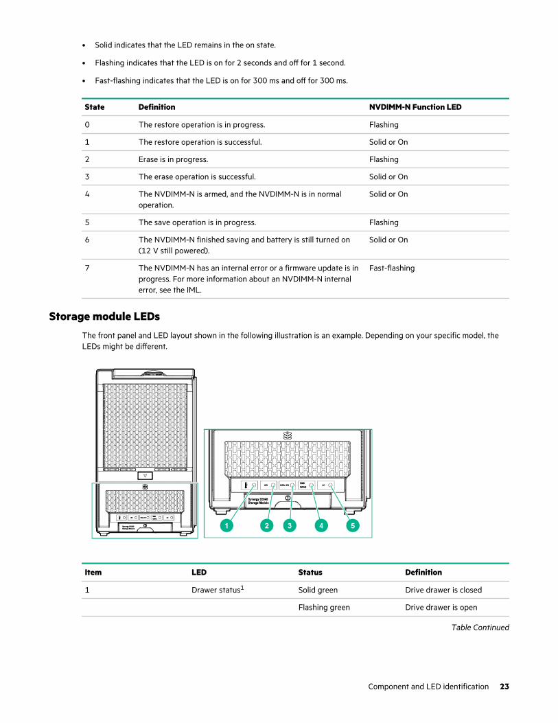
Storage module LEDsThe front panel and LED layout shown in the following illustration is an example. Depending on your specific model, theLEDs might be different.
Item LED Status Definition
1 Drawer status1 Solid green Drive drawer is closed
Flashing green Drive drawer is open
Table Continued
Component and LED identification 23
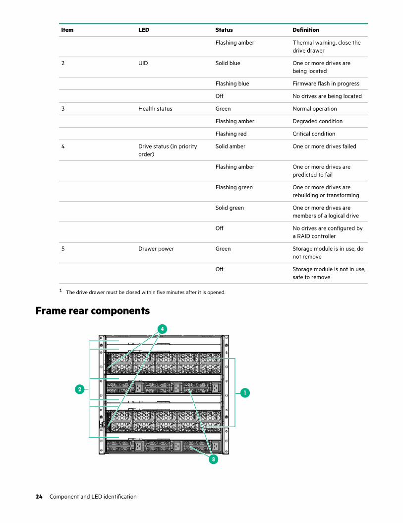
Item LED Status Definition
Flashing amber Thermal warning, close thedrive drawer
2 UID Solid blue One or more drives arebeing located
Flashing blue Firmware flash in progress
Off No drives are being located
3 Health status Green Normal operation
Flashing amber Degraded condition
Flashing red Critical condition
4 Drive status (in priorityorder)
Solid amber One or more drives failed
Flashing amber One or more drives arepredicted to fail
Flashing green One or more drives arerebuilding or transforming
Solid green One or more drives aremembers of a logical drive
Off No drives are configured bya RAID controller
5 Drawer power Green Storage module is in use, donot remove
Off Storage module is not in use,safe to remove
1 The drive drawer must be closed within five minutes after it is opened.
Frame rear components
24 Component and LED identification
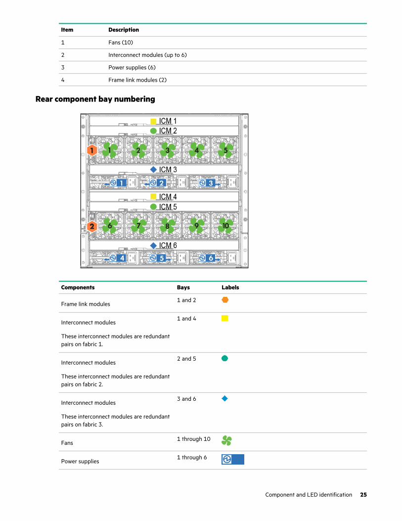
Item Description
1 Fans (10)
2 Interconnect modules (up to 6)
3 Power supplies (6)
4 Frame link modules (2)
Rear component bay numbering
Components Bays Labels
Frame link modules1 and 2
Interconnect modules
These interconnect modules are redundantpairs on fabric 1.
1 and 4
Interconnect modules
These interconnect modules are redundantpairs on fabric 2.
2 and 5
Interconnect modules
These interconnect modules are redundantpairs on fabric 3.
3 and 6
Fans1 through 10
Power supplies1 through 6
Component and LED identification 25
NOTE: The arrow direction on each of the power supply icons indicates the recommended power routing to either A-sideor B-side. For more information about A-side and B-side power distribution, see the HPE Synergy Cabling Guide in theHewlett Packard Enterprise Information Library (http://www.hpe.com/info/synergy-cabling-guide).
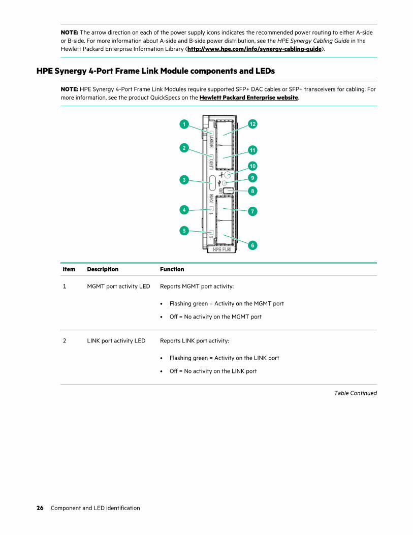
HPE Synergy 4-Port Frame Link Module components and LEDs
NOTE: HPE Synergy 4-Port Frame Link Modules require supported SFP+ DAC cables or SFP+ transceivers for cabling. Formore information, see the product QuickSpecs on the Hewlett Packard Enterprise website.
Item Description Function
1 MGMT port activity LED Reports MGMT port activity:
• Flashing green = Activity on the MGMT port
• Off = No activity on the MGMT port
2 LINK port activity LED Reports LINK port activity:
• Flashing green = Activity on the LINK port
• Off = No activity on the LINK port
Table Continued
26 Component and LED identification

Item Description Function
3 KVM portNOTE: Connection to the KVM port requires an HPE Synergy 4-Port Frame LinkModule USB Adapter.
NOTE: Supports storage devices that are USB 2.0 compatible.
When an HPE Synergy 4-Port Frame Link Module USB Adapter is installed, theHPE Synergy 4-Port Frame Link Module:
• Allows connection to the frame using a supported USB device.
Devices include a keyboard or mouse for connecting to the HPE SynergyConsole. To connect multiple devices, a USB hub (not included) is required.
• Allows connection to the frame using a monitor device or an active monitorport adapter.
Used for performing a USB recovery frame link module firmware update.
4 Appliance port 1connectivity LED
Reserved for future use.
5 Appliance port 2connectivity LED
Reserved for future use.
6 Appliance port 2 Reserved for future use.
7 Appliance port 1 Reserved for future use.
8 UID button Toggles the UID LED on or off.
• Solid blue = Activated
• Off = Deactivated
• Flashing blue = Firmware upgrade is in progress on the frame link module.
Do not remove either frame link module while the UID LED is flashing.
9 USB adapter thumbscrewconnection
For securing an HPE Synergy 4-Port Frame Link Module USB Adapter to the HPESynergy 4-Port Frame Link Module.
Table Continued
Component and LED identification 27
Item Description Function
10 Health LED Provides the health status of the frame link module.
• Solid green = Normal operation
• Flashing amber = Warning
• Flashing red = Critical error
If the Health LED indicates a warning or a critical error, connect to HPEOneView or to the HPE Synergy Console for more information andtroubleshooting assistance.
11 LINK port SFP+ connector that provides the following functions:
IMPORTANT: Use supported SFP+ 10GbE DAC cables or transceivers forLINK port connections. For more information, see the product QuickSpecson the Hewlett Packard Enterprise website.
• Provides high availability management network connectivity between:
◦ LINK ports on two frame link modules in the same frame for a single frameconfiguration
◦ Frame link modules in different frames as part of a management networkring in a multiframe configuration
• Provides management ring (frame link topology) connectivity for automaticframe discovery by HPE OneView.
12 MGMT port SFP+ connector that provides the following functions:
IMPORTANT: Use supported SFP+ DAC cables or transceivers for MGMTport connections. For more information, see the product QuickSpecs on the Hewlett Packard Enterprise website.
IMPORTANT: The transceiver or cable used must match the port speed ofthe switch used for management network connectivity.
• Provides a management uplink to the management network.
• 10GbE or 1GbE based on the cable or transceiver used.
28 Component and LED identification
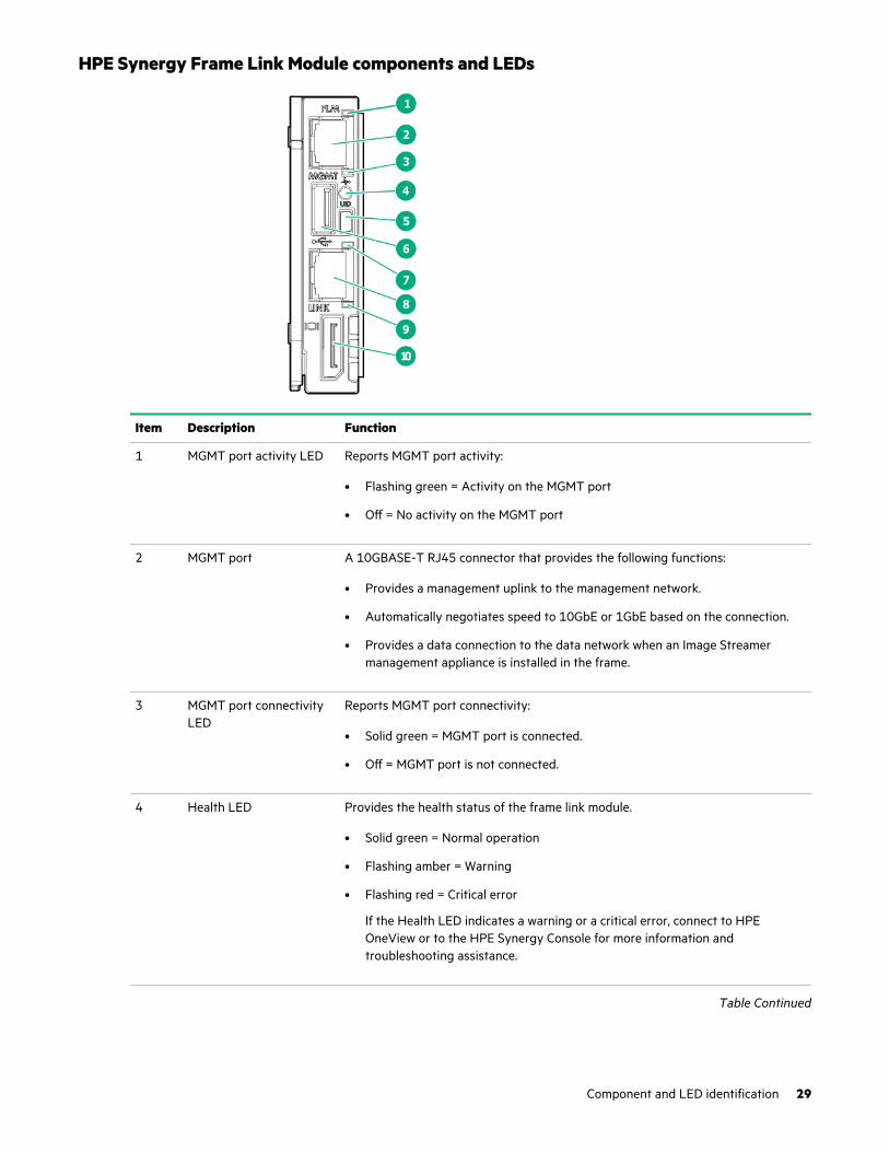
HPE Synergy Frame Link Module components and LEDs
Item Description Function
1 MGMT port activity LED Reports MGMT port activity:
• Flashing green = Activity on the MGMT port
• Off = No activity on the MGMT port
2 MGMT port A 10GBASE-T RJ45 connector that provides the following functions:
• Provides a management uplink to the management network.
• Automatically negotiates speed to 10GbE or 1GbE based on the connection.
• Provides a data connection to the data network when an Image Streamermanagement appliance is installed in the frame.
3 MGMT port connectivityLED
Reports MGMT port connectivity:
• Solid green = MGMT port is connected.
• Off = MGMT port is not connected.
4 Health LED Provides the health status of the frame link module.
• Solid green = Normal operation
• Flashing amber = Warning
• Flashing red = Critical error
If the Health LED indicates a warning or a critical error, connect to HPEOneView or to the HPE Synergy Console for more information andtroubleshooting assistance.
Table Continued
Component and LED identification 29
Item Description Function
5 UID button Toggles the UID LED on or off.
• Solid blue = Activated
• Off = Deactivated
• Flashing blue = Firmware upgrade is in progress on the frame link module.
Do not remove either frame link module while the UID LED is flashing.
6 USB port Allows connection to the frame using a supported USB device. Devices include akeyboard or mouse for connecting to the HPE Synergy Console. To connectmultiple devices, a USB hub (not included) is required.
Used for performing a USB recovery frame link module firmware update.
7 LINK port activity LED Reports LINK port activity:
• Flashing green = Activity on the LINK port
• Off = No activity on the LINK port
8 LINK port A 10GBASE-T RJ45 connector that provides two functions:
• Provides high-availability management network connectivity between:
◦ LINK ports on two frame link modules in the same frame for a single frameconfiguration.
◦ Frame link modules in different frames as part of a management networkring in a multiframe configuration.
• Provides management ring (frame link topology) connectivity for automaticframe discovery by HPE OneView.
9 LINK port connectivityLED
Reports LINK port connectivity:
• Solid green = LINK port is connected.
• Off = LINK port is not connected.
10 Monitor port Allows connection to the frame using a monitor device or an active monitor portadapter.
30 Component and LED identification
Power supply LED
Power LED Condition
Off No input power to the power supply or power supply failure. Connect to the HPESynergy console and check for power supply error messages.
Solid green Normal operation
Flashing amber Warning. Connect to HPE OneView Hardware Setup to troubleshoot.
Fan LED
LED color Fan status
Solid green Normal operation
Flashing red Critical. Connect to HPE OneView Hardware Setup to troubleshoot.
Component and LED identification 31

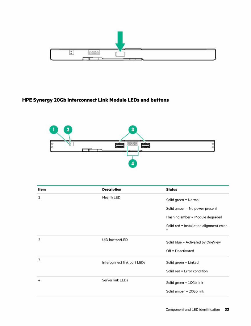
HPE Synergy 10Gb Interconnect Link Module LEDs and buttons
Item Description Status
1 Health LEDSolid green = Normal
Solid amber = No power present
Flashing amber = Module degraded
Solid red = Installation alignment error.*
2 UID button/LEDSolid blue = Activated by OneView
Off = Deactivated
3Interconnect link port LEDs Solid green = Linked
Solid red = Error condition
4 Server link LEDsSolid green = 10Gb link
* Remove and then reinstall the module.
HPE Synergy 10Gb Interconnect Module interconnect link portUse an interconnect link cable when linking port L1 to a master interconnect module.
32 Component and LED identification
HPE Synergy 20Gb Interconnect Link Module LEDs and buttons
Item Description Status
1 Health LEDSolid green = Normal
Solid amber = No power present
Flashing amber = Module degraded
Solid red = Installation alignment error.*
2 UID button/LEDSolid blue = Activated by OneView
Off = Deactivated
3Interconnect link port LEDs Solid green = Linked
Solid red = Error condition
4 Server link LEDsSolid green = 10Gb link
Solid amber = 20Gb link
Component and LED identification 33
* Remove and then reinstall the module.
HPE Synergy 20Gb Interconnect Link Module interconnect link portsUse an interconnect link cable when linking ports L1 or L2 to a master interconnect module.
HPE Synergy 50Gb Interconnect Link Module LEDs and buttons
Item Description Status
1 Health LEDSolid green = Normal
Off = No power present
Flashing amber = A fault condition exists
2 UID LEDSolid blue = Maintenance is required
Table Continued
34 Component and LED identification

Item Description Status
3 Server link LEDsSolid amber = 25Gb link
Solid orange = 50Gb link
Off = No link
4 Interconnect link port LEDsSolid green = Port connected from the HPE Synergy 50Gb InterconnectLink Module to HPE Virtual Connect SE 100Gb F32 Module.
Solid red = An error condition exists
Off = Port not connected from the HPE Synergy 50Gb Interconnect LinkModule to HPE Virtual Connect SE 100Gb F32 Module
HPE Synergy 50Gb Interconnect Link Module interconnect link portsUse an interconnect link cable when linking ports L1 or L2 to a master interconnect module.
NOTE: If you are running 25 Gb speeds, you only need one cable. If you are running 50 Gb speeds, you must connect twocables. If you are connecting two cables, you must populate L1 first.
HPE Virtual Connect SE 100Gb F8 Module for HPE Synergy LEDs and buttons
Component and LED identification 35

Item Description Status
1 Interconnect link port LEDs Solid green = Linked
Solid red = Error detected1.
Off = No link
2 QSFP28 uplink port LEDs If the port is in 40GbE or 100GbE mode, only the leftmost LED lights upwhen linked.
The four LEDs above each port correspond to the 10/25GbE or 8Gb/16Gb/32Gb FC channels of the port. The LEDs display one of four modes:
Ethernet ID mode:
• Solid green = The port is configured as an Uplink port.
• Solid orange = The port is configured as a Stacking Link port.
• Solid magenta = Configured as a Mirror to port.
• Off = The port is not configured as an Ethernet port.
PID mode:
• Solid green = The port is configured for Ethernet.
• Solid orange = The port is configured for Fibre Channel.
• Solid red = error.
• Off = The port is not configured.
Link/Activity mode:
• Solid green =
◦ 10Gb Ethernet link without activity
• Flashing green =
◦ 10Gb Ethernet activity
• Solid orange =
◦ 25Gb Ethernet link without activity
◦ 8Gb FC link without activity
• Flashing orange =
◦ 25Gb Ethernet link with activity
◦ 8Gb FC link with activity
• Solid magenta =
◦ 40Gb Ethernet link without activity
◦ 16Gb FC link without activity
Table Continued
36 Component and LED identification
Item Description Status
• Flashing magenta =
◦ 40Gb Ethernet link with activity
◦ 16Gb FC link with activity
• Solid cyan =
◦ 100Gb Ethernet link without activity
◦ 32Gb FC link without activity
• Flashing cyan =
◦ 100Gb Ethernet link with activity
◦ 32Gb FC link with activity
• Off = No link or not configured
Fibre Channel (FC) ID mode:
• Solid green = Logged into Attached Switch.
• Solid orange = Not logged into Attached Switch.
• Off = The port is not configured as an FC port.
To switch between the LED modes, press the Mode button.
3 SFP+ Image Streamer portLEDs
Left LED
Link/Activity mode:
• Off = No Link
• Solid green = Ethernet linked at 10Gb
PID:
• Off = Not configured
• Solid blue = Port ID
• Solid green = Configured for Ethernet
• Solid red = Error
Ethernet:
• Off = Not Ethernet
• Solid green = Configured for Ethernet
Fibre Channel:
Always off
Table Continued
Component and LED identification 37

Item Description Status
Right LED
Link/Activity mode:
• Off = No activity
• Flashing green = Activity at 10Gb
PID:
Always off
Ethernet:
Always off
Fibre Channel:
Always off
4 Fibre Channel (FC) modeLED
Solid green = FC mode is selected.
5 Ethernet mode LED Solid green = Ethernet mode is selected.
6 PID mode LED Solid green = PID mode is selected.
7 Link/Activity mode LED2 Solid green = Link/Activity mode is selected.
8 Health LED Solid green = Normal
Flashing amber = There is a fault condition
Flashing red = Critical fault detected
Solid red = No power present
9 Mode button Press and hold the Mode button for more than 5 seconds to reset.
Solid green = There are four LEDs that indicate the operating mode for thePort LEDs. The operating mode is selected by pressing the Mode button onthe front panel. The LED mode state determines which of the four ModeLEDs is lit.
10 UID LED Solid blue = Activated
Flashing blue = Firmware upgrade in progress
Off = Deactivated
1 See HPE OneView (http://www.hpe.com/info/oneview/docs)2 When illuminated, the QSFP28 port LEDs indicate the port operating states for each of the uplink ports in the selected mode.
38 Component and LED identification

HPE Virtual Connect SE 100Gb F32 Module for HPE Synergy components
Item Component Description
1 Interconnect link ports L1–L4
For linking Interconnect Link modules
2 QSFP28 uplink ports Q1–Q6
10/25/40/100Gb Ethernet
or 8/16/32Gb Fibre Channel
3 SFP+ uplink ports X1-X2 For Image Streamer
4 Micro-USB For Serial Port (115200,8,1)
5 USB USB 3.0 port (unused)
6 QSFP28 uplink ports Q7–Q8
For Ethernet stacking links
HPE Virtual Connect SE 40Gb F8 Module for HPE Synergy LEDs and buttons
Component and LED identification 39

Item Description Status
1 Interconnect link port LEDs Solid green = Linked
Solid red = Error detected1.
Off = No link
2 QSFP+ port LEDs The four LEDs above each port correspond to the 10GbE or 8Gb FCchannels of the port. The LEDs display one of four modes:
Ethernet mode:
• Solid green = The port is configured as an Ethernet port.
• Off = The port is not configured as an Ethernet port.
PID mode:
• Solid green = The port is configured as an uplink port.
• Solid amber = The port is configured as a stacking port.
• Solid purple = The port is configured as a mirrored port.
• Solid red = Error.
• Solid blue = Activated by OneView for port identification.
• Off = The port is not configured.
Link/Activity mode:
• Solid green = 10Gb Ethernet link
• Flashing green = 10Gb Ethernet activity
• Solid amber = 8Gb FC link
• Flashing amber = 8Gb FC activity
• Solid purple = 40Gb Ethernet link
• Flashing purple = 40Gb Ethernet activity
• Solid Red = Error
• Off = No link
Fibre Channel (FC) mode:
• Solid green = The port is configured as an FC port.
• Off = The port is not configured as an FC port.
To switch between the LED modes, press the NEXT button.
3 NEXT button Selects the QSFP+ port LED mode.
4 Reset pin-hole Resets the module
Table Continued
40 Component and LED identification
Item Description Status
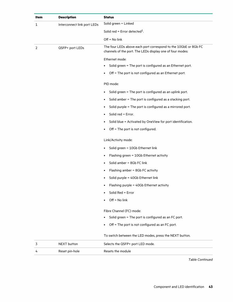
5 UID LED/button Solid blue = Activated
Flashing blue = Firmware upgrade in progress
Off = Deactivated
6 Health LED Solid green = Normal
Solid amber = No power present
Flashing amber = Module degraded
Solid red = A physical alignment error exists.2
7 Link/Activity mode LED3 Solid green = Link/Activity mode is selected.
8 PID mode LED3 Solid green = PID mode is selected.
9 Ethernet mode LED3 Solid green = Ethernet mode is selected.
10 Fibre Channel (FC) modeLED3
Solid green = FC mode is selected.
1 See OneView (http://www.hpe.com/info/oneview/docs)2 Remove and then reinstall the module.3 When illuminated, QSFP+ port LEDs indicate the port operating states for each of the uplink ports in the selected mode.
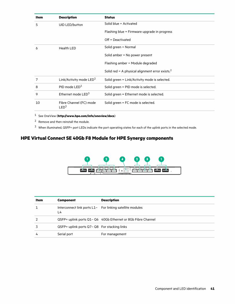
HPE Virtual Connect SE 40Gb F8 Module for HPE Synergy components
Item Component Description
1 Interconnect link ports L1–L4
For linking satellite modules
2 QSFP+ uplink ports Q1– Q6 40Gb Ethernet or 8Gb Fibre Channel
3 QSFP+ uplink ports Q7– Q8 For stacking links
4 Serial port For management
Component and LED identification 41
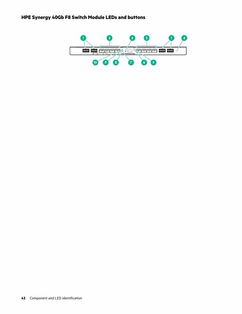
HPE Synergy 40Gb F8 Switch Module LEDs and buttons
42 Component and LED identification
Item Description Status
1 Interconnect link port LEDs Solid green = Linked
Solid red = Error detected1.
Off = No link
2 QSFP+ port LEDs The four LEDs above each port correspond to the 10GbE or 8Gb FCchannels of the port. The LEDs display one of four modes:
Ethernet mode:
• Solid green = The port is configured as an Ethernet port.
• Off = The port is not configured as an Ethernet port.
PID mode:
• Solid green = The port is configured as an uplink port.
• Solid amber = The port is configured as a stacking port.
• Solid purple = The port is configured as a mirrored port.
• Solid red = Error.
• Solid blue = Activated by OneView for port identification.
• Off = The port is not configured.
Link/Activity mode:
• Solid green = 10Gb Ethernet link
• Flashing green = 10Gb Ethernet activity
• Solid amber = 8Gb FC link
• Flashing amber = 8Gb FC activity
• Solid purple = 40Gb Ethernet link
• Flashing purple = 40Gb Ethernet activity
• Solid Red = Error
• Off = No link
Fibre Channel (FC) mode:
• Solid green = The port is configured as an FC port.
• Off = The port is not configured as an FC port.
To switch between the LED modes, press the NEXT button.
3 NEXT button Selects the QSFP+ port LED mode.
4 Reset pin-hole Resets the module
Table Continued
Component and LED identification 43
Item Description Status
5 UID LED/button Solid blue = Activated
Flashing blue = Firmware upgrade in progress
Off = Deactivated
6 Health LED Solid green = Normal
Solid amber = No power present
Flashing amber = Module degraded
Solid red = A physical alignment error exists.2
7 Link/Activity mode LED3 Solid green = Link/Activity mode is selected.
8 PID mode LED3 Solid green = PID mode is selected.
9 Ethernet mode LED3 Solid green = Ethernet mode is selected.
10 Fibre Channel (FC) modeLED3
Solid green = FC mode is selected.
1 See OneView (http://www.hpe.com/info/oneview/docs)2 Remove and then reinstall the module.3 When illuminated, QSFP+ port LEDs indicate the port operating states for each of the uplink ports in the selected mode.
HPE Synergy 40Gb F8 Switch Module components
Item Component Description
1 Interconnect link ports L1–L4
For linking satellite modules
2 QSFP+ uplink ports Q1– Q6 40Gb Ethernet or 8Gb Fibre Channel
3 QSFP+ uplink ports Q7– Q8 40Gb Ethernet
4 Serial port For management
44 Component and LED identification

Mellanox SH2200 Switch Module for HPE Synergy LEDs and components
Item Description
1 Serial port
2 QSFP+ uplink ports (8)
3 UID LED
Solid blue = Activated
Flashing blue = Firmware upgrade in progress.
Off = Deactivated
4 Health LED
Off = No power present
Solid green = Normal
Flashing amber = Fault
Solid red = CANMIC boot failure
5 QSFP+ LEDs
Off = Link is down
Solid green = Link is active
Flashing green = Data activity is proportional to datatransfer
Flashing orange = Link error
Component and LED identification 45
Installation
Installing the Synergy system components
Procedure
1. Unpack the system.
2. Remove components from the frame.
3. For rack-free installations, set up the frame on an appropriate surface, and then install the frame options.
4. For rack installations, install the frame into the rack, and then install the frame options.
5. Install the frame components into the frame.
6. Connect the frame components in the frame.
7. Connect the AC power cables and power up the frame.
8. Configure the frame using the Composer.
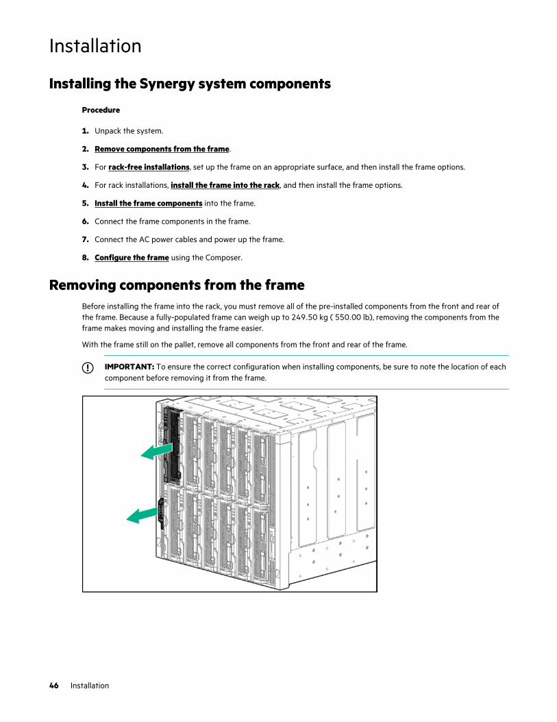
Removing components from the frameBefore installing the frame into the rack, you must remove all of the pre-installed components from the front and rear ofthe frame. Because a fully-populated frame can weigh up to 249.50 kg ( 550.00 lb), removing the components from theframe makes moving and installing the frame easier.
With the frame still on the pallet, remove all components from the front and rear of the frame.
IMPORTANT: To ensure the correct configuration when installing components, be sure to note the location of eachcomponent before removing it from the frame.
46 Installation

For specific instructions concerning removing the components, see the HPE Synergy 12000 Frame Maintenance andService Guide.
Installing the frame in a rack-free environment
WARNING: To reduce the risk of personal injury or damage to the equipment in a rack-free environment:
• Never stack the frame on top of another frame.
• Never place equipment on top of the frame.
• Never place the frame on a surface that cannot support up to 249.50 kg ( 550.00 lb).
Procedure
1. Select the location for the frame.
For more information, see Rack-free environment requirements on page 9.
2. Remove components from the frame.
3. Place the frame on a flat, sturdy surface to support the frame.
4. Complete the component installation for your configuration.
Installing the frame in a rack
CAUTION: Always plan the rack installation so that the heaviest item is on the bottom of the rack. Install theheaviest item first, and continue to populate the rack from the bottom to the top.
NOTE: Up to four 10U frames can be installed in a 42U rack. If you are installing more than one frame, install the firstframe in the bottom of the rack, and then install additional frames by moving up the rack with each subsequent frame.Plan rack installation carefully because it is difficult to change the location of components after they are installed.
Installation 47

Procedure
1. Remove components from the frame.
2. Use the rack template to mark the locations for the rack rails.
3. Install the rack rails and cage nuts for each frame.
For more information, see the appropriate section according to the type of rack being used.
4. Install the frame into the rack.
5. Complete the component installation for your configuration.
Measuring with the rack templateThe HPE Synergy 12000 Frame Rack Template ships with the frame. The rack template provides detailed instructions onwhere to position the frame and rack rails, and where to install the cage or clip nuts. Each frame kit includes the rack railsrecommended for that frame.
NOTE: Four cage nuts and four clip nuts are included with the frame. Always use cage nuts in racks with square holes.Always use clip nuts in racks with round holes.
When installing multiple frames, install the rack rails and cage nuts for one frame, and then install the frame. Repeat foreach additional frame.
Procedure
1. Install lower cage nuts (left and right) in the front of the rack at the bottom of the fourth U (10 holes up on thetemplate).
2. Install the upper cage nuts (left and right) in the front of the rack at the bottom of the tenth U (28 holes up on thetemplate).
3. Install the rack rails.
Installing the rack rails for a square-hole rackRack rails are marked "LEFT" and "RIGHT" for identification. The rail release levers are used only when removing the railfrom the rack.
48 Installation

Procedure
1. Begin with the left rack rail. Shorten the rail.
2. Align the rear end of the rail with the rack rear column.
3. Position the rail tabs next to the square openings in the rack rear column.
4. Keeping the rail level, insert the rear rail tabs into the rack rear column, and push the tabs down into place.
5. Extend the front of the rack rail to the rack front column.
6. Position the rail tabs next to the square openings in the rack front column.
7. Insert the front rail tabs into the rack front column and push the tabs down into place.
Installation 49
8. Repeat the procedure for the right rack rail.
The installation is complete.
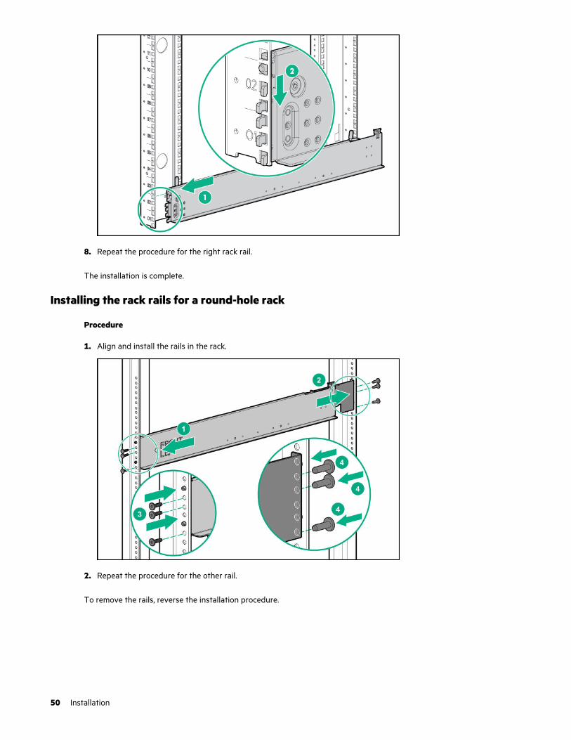
Installing the rack rails for a round-hole rack
Procedure
1. Align and install the rails in the rack.
2. Repeat the procedure for the other rail.
To remove the rails, reverse the installation procedure.
50 Installation

Installing the frame into the rack
WARNING: When lifting the frame with the optional removable handles, always use at least four people to lift theframe into the rack. If the frame is being loaded into the rack above chest level, a fifth person must assist withaligning the frame with the rails while the other four people support the weight of the frame.
NOTE: You can install the frame into the rack using a mechanical lift. When using a mechanical lift, two people arerequired for the frame installation. If you choose the mechanical lift installation, resume the frame installation at step 5.
Procedure
1. Attach the lift handles to the frame.
a. Align each lift handle to the frame spools.
b. Press the release button, and then pull the lift handle up until it locks in place.
2. Line up the frame with the rack, set the back end of the frame on the rack rails and slide it in.
Installation 51

3. Slide the frame into the rack until the rear lift handles are close to the rack. While still supporting the frame with thefront lift handles, remove the rear lift handles from each side of the frame, and then slide the frame halfway into therack.
4. Slide the frame into the rack until the front lift handles are close to the rack. Remove the front lift handles from eachside of the frame, and then slide the frame fully into the rack.
52 Installation

5. Remove the left and right frame bezels from front of the frame by inserting your finger in the hole at the bottom of theframe bezel and pull out and up, then pull the top of the frame bezel away from the frame.
6. Tighten the thumbscrews with a T-25 Torx screwdriver to secure the frame to the rack.
Installation 53
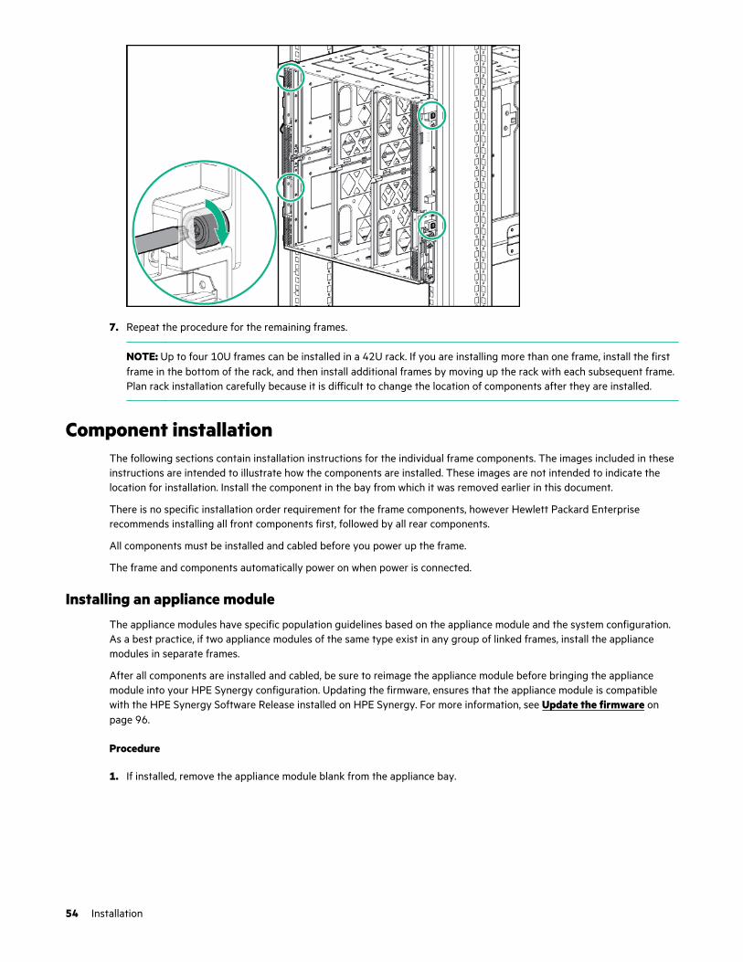
7. Repeat the procedure for the remaining frames.
NOTE: Up to four 10U frames can be installed in a 42U rack. If you are installing more than one frame, install the firstframe in the bottom of the rack, and then install additional frames by moving up the rack with each subsequent frame.Plan rack installation carefully because it is difficult to change the location of components after they are installed.
Component installationThe following sections contain installation instructions for the individual frame components. The images included in theseinstructions are intended to illustrate how the components are installed. These images are not intended to indicate thelocation for installation. Install the component in the bay from which it was removed earlier in this document.
There is no specific installation order requirement for the frame components, however Hewlett Packard Enterpriserecommends installing all front components first, followed by all rear components.
All components must be installed and cabled before you power up the frame.
The frame and components automatically power on when power is connected.
Installing an appliance moduleThe appliance modules have specific population guidelines based on the appliance module and the system configuration.As a best practice, if two appliance modules of the same type exist in any group of linked frames, install the appliancemodules in separate frames.
After all components are installed and cabled, be sure to reimage the appliance module before bringing the appliancemodule into your HPE Synergy configuration. Updating the firmware, ensures that the appliance module is compatiblewith the HPE Synergy Software Release installed on HPE Synergy. For more information, see Update the firmware onpage 96.
Procedure
1. If installed, remove the appliance module blank from the appliance bay.
54 Installation
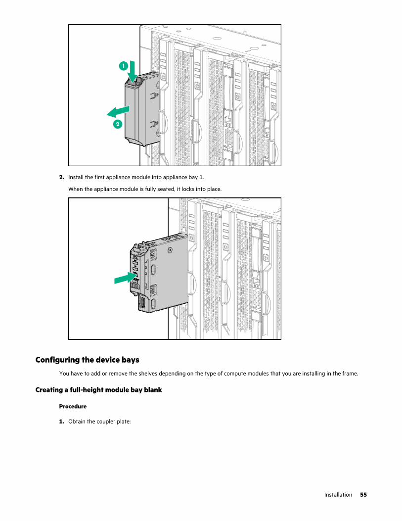
2. Install the first appliance module into appliance bay 1.
When the appliance module is fully seated, it locks into place.
Configuring the device baysYou have to add or remove the shelves depending on the type of compute modules that you are installing in the frame.
Creating a full-height module bay blank
Procedure
1. Obtain the coupler plate:
Installation 55
• If you are using a module bay blank that came with the frame, the coupler plate can be found with the contents ofthe full-height device shipping box.
• If you are using a device bay blank that you purchased as an option, remove the coupler plate from inside theblank.
2. Fit the coupler plate into the slots on top of the blank, and then slide the coupler plate back until it snaps into place.
3. Fit the slots on the bottom of the second blank on to the coupler plate tabs, and then slide the second blank forwarduntil it snaps in place.
4. Install the full-height blank into the device bay.
56 Installation
Removing a device bay shelf
Procedure
1. Press and hold the release latches to release the locking mechanism.
2. Slide the removable shelf out of the frame.
Installing a device bay shelf
The frame has a slot and notch on the device bay walls that is used to guide the shelf when inserted.
Procedure
1. Locate the slot and notch shelf guides.
2. Press and hold the latches of the removable shelf and insert into the device bay using the shelf guides.
Installation 57
3. When the shelf is fully inserted, release the latches to lock the shelf in place.
Removing the half shelf
Prerequisites
If installed, remove the full-height compute module from the adjacent bay before removing and replacing the half shelf.
Procedure
1. To release the locking mechanism, press and hold the shelf release latch.
2. Slide the half shelf towards the front of the frame, and then pull away from the frame.
58 Installation

Replacing the half shelf
Procedure
1. Align the spools to the keyhole slots in the frame.
2. Insert the spools into the keyhole slots and slide the half shelf towards the rear of the frame until it locks into place.
Installation 59
Installing the half shelf
Procedure
1. Align the spools to the keyhole slots in the frame.
2. Insert the spools into the keyhole slots and slide the half shelf towards the rear of the frame until it locks into place.
60 Installation

Installing compute modulesDepending on the compute modules installed in your frame:
• Install device bay partitions.
• Install a full-height compute module.
• Install a half-height compute module.
Installing a full-height compute module
The HPE Synergy 12000 Frame ships with three device bay shelves installed to support a 12 half-height compute moduleconfiguration. To install a full-height compute module, remove the device bay shelves and corresponding blanks.
Procedure
1. Remove the blanks.
Installation 61
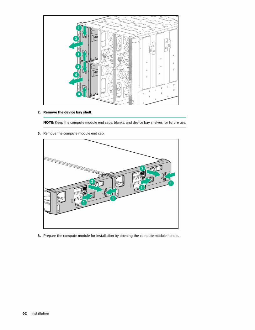
2. Remove the device bay shelf.
NOTE: Keep the compute module end caps, blanks, and device bay shelves for future use.
3. Remove the compute module end cap.
4. Prepare the compute module for installation by opening the compute module handle.
62 Installation
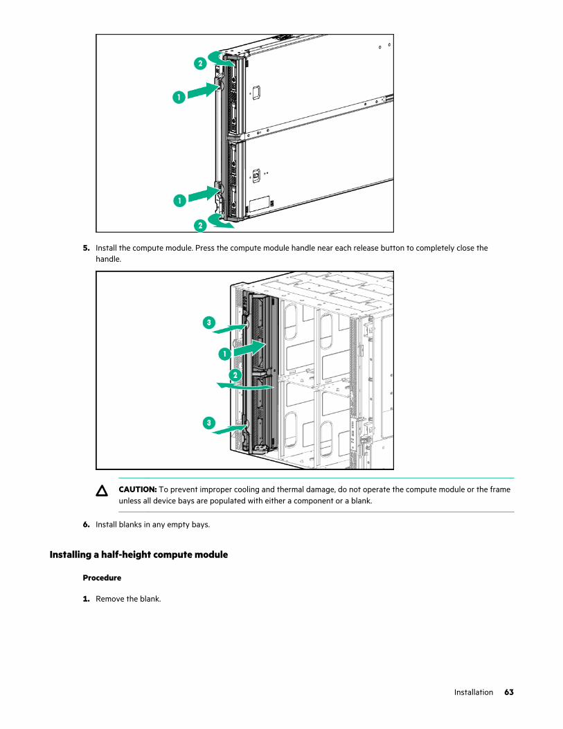
5. Install the compute module. Press the compute module handle near each release button to completely close thehandle.
CAUTION: To prevent improper cooling and thermal damage, do not operate the compute module or the frameunless all device bays are populated with either a component or a blank.
6. Install blanks in any empty bays.
Installing a half-height compute module
Procedure
1. Remove the blank.
Installation 63

2. If required, install the device bay shelf.
NOTE: Keep the compute module end caps, blanks, and device bay shelves for future use.
3. Remove the compute module end cap.
4. Prepare the compute module for installation by opening the compute module handle.
64 Installation
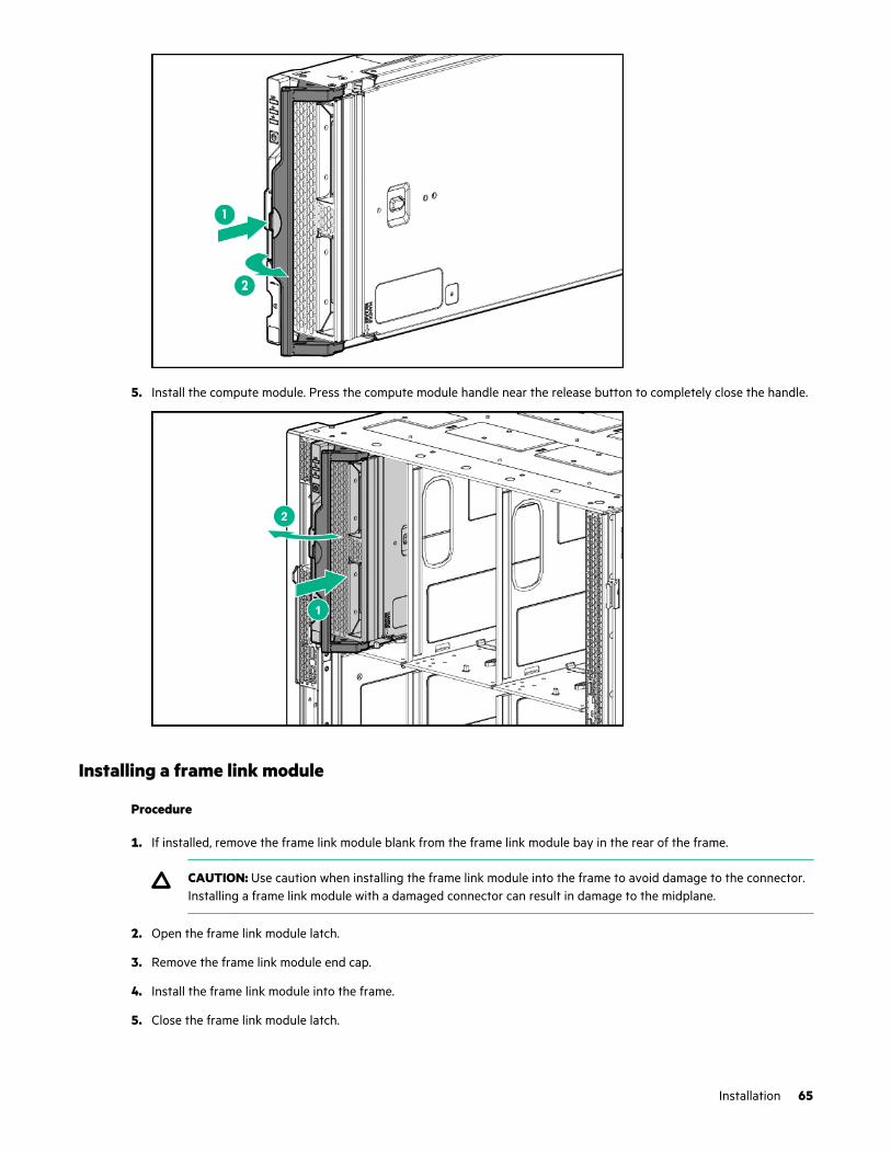
5. Install the compute module. Press the compute module handle near the release button to completely close the handle.
Installing a frame link module
Procedure
1. If installed, remove the frame link module blank from the frame link module bay in the rear of the frame.
CAUTION: Use caution when installing the frame link module into the frame to avoid damage to the connector.Installing a frame link module with a damaged connector can result in damage to the midplane.
2. Open the frame link module latch.
3. Remove the frame link module end cap.
4. Install the frame link module into the frame.
5. Close the frame link module latch.
Installation 65

Installing the storage module
Prerequisites
CAUTION: Installation of the storage module into the frame without drives requires one person. Installation of thestorage module into the frame with drives already installed requires two people.
Be sure that you have the required number of people to lift the storage module into the frame.
Procedure
1. Before installing the storage module, press down the storage module release latch to open the storage module handle.
NOTE: The storage module handle arrives packaged in the closed position and must be opened prior to installation.
2. Install the storage module. To fully seat the storage module, be sure to close the storage module handle. When thehandle is completely closed, the release latch clicks into place.
66 Installation

3. To add drives to the drive drawer, see Installing the drives in the storage module.
More information
Installing drives in the storage module on page 67
Installing drives in the storage module
Procedure
1. Press the drive drawer release latch and pull out the drawer with the driver drawer release handle.
2. Prepare the drives for installation.
Installation 67
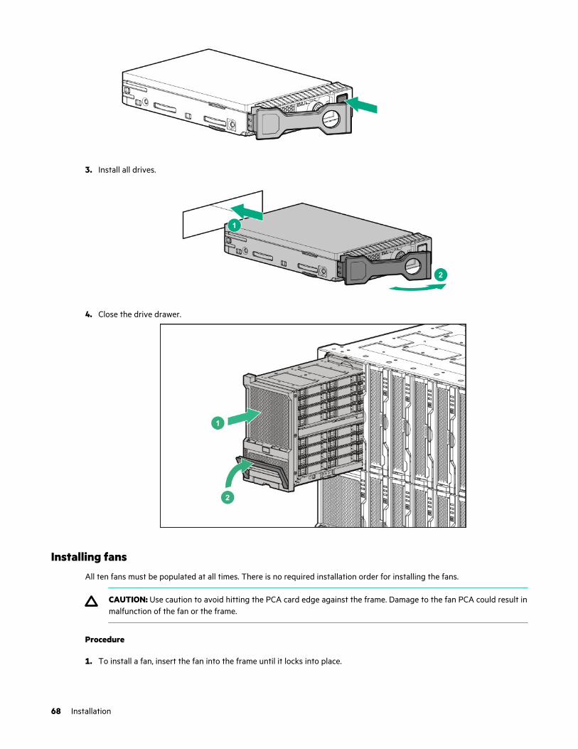
3. Install all drives.
4. Close the drive drawer.
Installing fansAll ten fans must be populated at all times. There is no required installation order for installing the fans.
CAUTION: Use caution to avoid hitting the PCA card edge against the frame. Damage to the fan PCA could result inmalfunction of the fan or the frame.
Procedure
1. To install a fan, insert the fan into the frame until it locks into place.
68 Installation
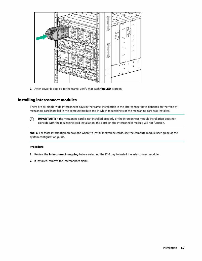
2. After power is applied to the frame, verify that each fan LED is green.
Installing interconnect modulesThere are six single-wide interconnect bays in the frame. Installation in the interconnect bays depends on the type ofmezzanine card installed in the compute module and in which mezzanine slot the mezzanine card was installed.
IMPORTANT: If the mezzanine card is not installed properly or the interconnect module installation does notcoincide with the mezzanine card installation, the ports on the interconnect module will not function.
NOTE: For more information on how and where to install mezzanine cards, see the compute module user guide or thesystem configuration guide.
Procedure
1. Review the interconnect mapping before selecting the ICM bay to install the interconnect module.
2. If installed, remove the interconnect blank.
Installation 69
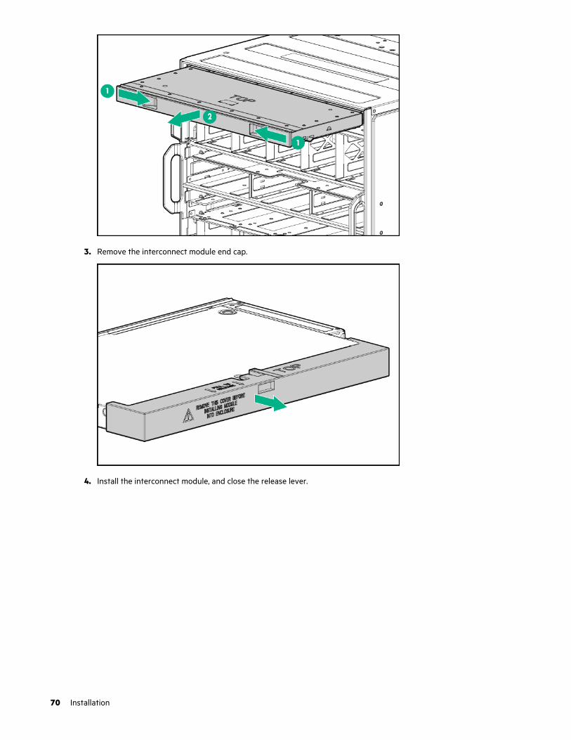
3. Remove the interconnect module end cap.
4. Install the interconnect module, and close the release lever.
70 Installation

Interconnect module configurations
The HPE Synergy 12000 Frame supports a pair of redundant interconnect modules for each of the three fabrics. HewlettPackard Enterprise recommends the following best practices:
• Fabric 1 primary use—Storage
• Fabric 2 primary use—Storage or networking
• Fabric 3 primary use—Networking
NOTE: Though each fabric has a recommended primary use, it is not required to use the primary use case. If a fabric isnot being used for its primary use, it can still be used for another purpose, within the allowances.
Fabric Usage ICM description
Fabric 1
ICM Bays 1 and 4
Storage
(Primary)
HPE Synergy 12Gb SAS Connection Module
HPE Virtual Connect SE 32Gb FC Module for HPE Synergy
Brocade 32Gb FC Fibre Channel Switch Module
Brocade 16 Gb Fibre Channel SAN Switch Module for HPESynergy
HPE Virtual Connect SE 16Gb FC Module for HPE Synergy
Fabric 2
ICM Bays 2 and 5
Storage HPE Virtual Connect SE 32Gb FC Module for HPE Synergy
Brocade 32Gb FC Fibre Channel Switch Module
HPE Virtual Connect SE 16Gb FC Module for HPE Synergy
Table Continued
Installation 71

Fabric Usage ICM description
Brocade 16 Gb Fibre Channel SAN Switch Module for HPESynergy
Fabric 2
ICM Bays 2 and 5
Networking HPE Synergy 40Gb F8 Switch Module
HPE Virtual Connect SE 100Gb F32 Module for HPE Synergy
HPE Synergy 50Gb Interconnect Link Module
HPE Virtual Connect SE 40Gb F8 Module for HPE Synergy
HPE Synergy 20Gb Interconnect Link Module
HPE Synergy 10Gb Interconnect Link Module
HPE Synergy 10Gb Pass-Thru Module
Mellanox SH2200 25/50Gb Switch
Fabric 3
ICM Bays 3 and 6
Networking
(Primary)
HPE Synergy 40Gb F8 Switch Module
HPE Virtual Connect SE 100Gb F32 Module for HPE Synergy
HPE Synergy 50Gb Interconnect Link Module
HPE Virtual Connect SE 40Gb F8 Module for HPE Synergy
HPE Synergy 20Gb Interconnect Link Module
HPE Synergy 10Gb Interconnect Link Module
HPE Synergy 10Gb Pass-Thru Module
Brocade 16Gb Fibre Channel SAN Switch Module for HPESynergy
Mellanox SH2200 25/50Gb Switch
Interconnect module installation guidelines
Always adhere to the following guidelines when planning and installing the interconnect modules in HPE Synergy frames:
• The interconnect modules are listed in order of priority from top to bottom within a fabric. For example, if the HPESynergy 12Gb SAS Connection Module is installed, it is supported only in fabric 1 and therefore, that fabric solution isthe first priority for fabric 1. If the HPE Synergy 12Gb SAS Connection Module is not used, then fabric 1 is available tobe used by one of the supported HPE Synergy Fibre Channel interconnect modules.
• Both ICM bays within a fabric must contain the same interconnect module, unless the fabric is a Master/Satellite fabric.In a Master/Satellite fabric, one or more satellite modules can be used along with a master module to form a fabric.
• All interconnect link modules that comprise a Master/Satellite fabric must be installed in the same interconnect baynumber as the corresponding master interconnect module. For example, given a three-frame configuration where themaster interconnect module is installed in ICM bay 3 in one frame, the two satellite interconnect link modules in thesecond and third frames must also be installed in ICM bay 3.
72 Installation
Master interconnect module with interconnect link module configurations
The following interconnect modules can be configured as the master switch, with interconnect link modules to support themaster interconnect module:
• HPE Synergy Virtual Connect SE 40 Gb F8 Module
• HPE Synergy 40Gb F8 Switch Module
• HPE Virtual Connect SE 100Gb F32 Module for HPE Synergy
From one to four interconnect link modules are required to support the master interconnect module when using thefollowing interconnect link modules:
• HPE Synergy 10Gb Interconnect Link Module
• HPE Synergy 50Gb Interconnect Link Module in 25G mode
From one to two interconnect link modules are required to support the master interconnect module when using thefollowing interconnect link modules:
• HPE Synergy 20Gb Interconnect Link Module
• HPE Synergy 50Gb Interconnect Link Module in 50G mode
If redundancy is required, then two master switches are required per fabric. For the best availability with two or moreframes, the two switches or VC modules must be installed in different frames.
As an example of a redundant fabric 3 solution, one interconnect module or VC module would be installed in ICM bay 3 inone frame and the second interconnect module or VC module would be installed in ICM bay 6 in another frame. ICM baysfor the particular fabric that do not contain the interconnect modules or VC modules would contain the interconnect linkmodules, providing redundancy for either an interconnect module failure or frame failure.
The number of interconnect link cables is different depending on your Master/Satellite configuration:
Master Satellite Number of interconnect link cables
HPE Virtual Connect SE 100Gb F32Module for HPE Synergy
HPE Synergy 50Gb Interconnect LinkModule
1 (for 25Gb speed)
2 (for 50Gb speed)
HPE Synergy 40Gb F8 Switch Module,or the HPE Virtual Connect SE 100GbF32 Module for HPE Synergy
HPE Synergy 20Gb Interconnect LinkModule
2
HPE Synergy 40Gb F8 Switch Module,or the HPE Virtual Connect SE 100GbF32 Module for HPE Synergy
HPE Synergy 10Gb Interconnect LinkModule
1
HPE Synergy Virtual Connect SE 40Gb F8 Module
HPE Synergy 20Gb Interconnect LinkModule
2
HPE Synergy Virtual Connect SE 40Gb F8 Module
HPE Synergy 10Gb Interconnect LinkModule
1
Installation 73
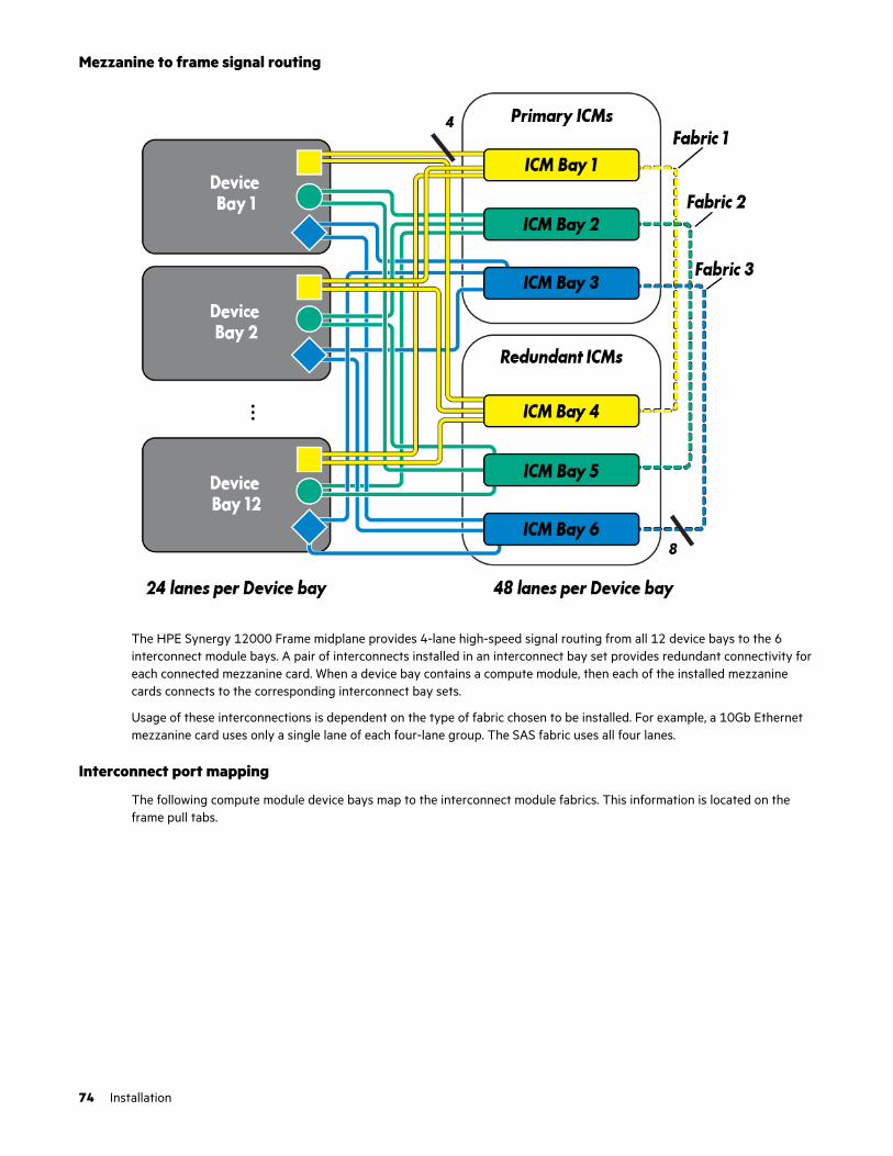
Mezzanine to frame signal routing
The HPE Synergy 12000 Frame midplane provides 4-lane high-speed signal routing from all 12 device bays to the 6interconnect module bays. A pair of interconnects installed in an interconnect bay set provides redundant connectivity foreach connected mezzanine card. When a device bay contains a compute module, then each of the installed mezzaninecards connects to the corresponding interconnect bay sets.
Usage of these interconnections is dependent on the type of fabric chosen to be installed. For example, a 10Gb Ethernetmezzanine card uses only a single lane of each four-lane group. The SAS fabric uses all four lanes.
Interconnect port mapping
The following compute module device bays map to the interconnect module fabrics. This information is located on theframe pull tabs.
74 Installation

The location of a mezzanine option in the compute module dictates the location of the corresponding interconnect modulein the rear of the frame.
Half-height compute module mezzanine connector definitions
NOTE: The compute module hood label includes the exact mezzanine card locations.
Item Mezz slot connector identification Supported card types Fabric Interconnectbay sets
1 Mezzanine slot 1 (M1) Type C and Type D 1 ICM 1 and 4
2 Mezzanine slot 2 (M2)1 Type C and Type D 2 ICM 2 and 5
3 Mezzanine slot 3 (M3) Type C only 3 ICM 3 and 6
1 When installing a mezzanine option in mezzanine slot 2, processor 2 must be installed.
Installation 75

Full-height compute module mezzanine connector definitions
NOTE: The compute module hood label includes the exact mezzanine card locations.
The symbols in the image correspond with symbols on the rear of the frame.
Item Mezz slot connector identification Supported card types Fabric Supported ICM bays
1 Mezzanine slot 1 (M1) Type C and Type D 1 ICM 1 and 4
2 Mezzanine slot 2 (M2)1 Type C and Type D 2 ICM 2 and 5
3 Mezzanine slot 3 (M3) Type C only 3 ICM 3 and 6
4 Mezzanine slot 4 (M4) Type C and Type D 1 ICM 1 and 4
5 Mezzanine slot 5 (M5)1 Type C and Type D 2 ICM 2 and 5
6 Mezzanine slot 6 (M6) Type C 3 ICM 3 and 6
1 When installing a mezzanine option in mezzanine slot 2, processor 3 must be installed. When installing a mezzanine option inmezzanine slot 5, processor 4 must be installed.
Installing power suppliesHPE Synergy supports several different types of HPE Synergy power supplies. For more information, see the HPE Synergy12000 Frame Quick Specs on the Hewlett Packard Enterprise Information Library (http://www.hpe.com/info/qs).
CAUTION: Mixing different types of power supplies in the same frame might:
• Limit or disable some power supply features including support for power redundancy.
• Cause the system to become unstable and might shut down.
To ensure access to all available features, all power supplies in the same frame should have the same output andefficiency ratings. Verify that all power supplies have the same part number and label color.
WARNING: To reduce the risk of personal injury from hot surfaces, allow the power supply and the power supplyblank to cool before touching them.
76 Installation

WARNING: To reduce the risk of electric shock or damage to the equipment, do not connect the power cord to thepower supply until the power supply is installed.
NOTE: When installed in the HPE Synergy 12000 Frame, the HPE 2900-3400W Hot Plug Platinum Power Supply onlysupports 230-240VAC input.
Procedure
1. Remove the power supply blank, or unplug the power cord and remove the power supply from the frame.
2. Remove the output connector cover from the new power supply.
3. Insert the power supply into the frame until it locks into place. The power supply is marked with TOP to ensure properorientation during installation.
4. Connect the power cord to the power supply.
5. Secure the power cord using the reusable zip tie attached to the power supply.
Installation 77
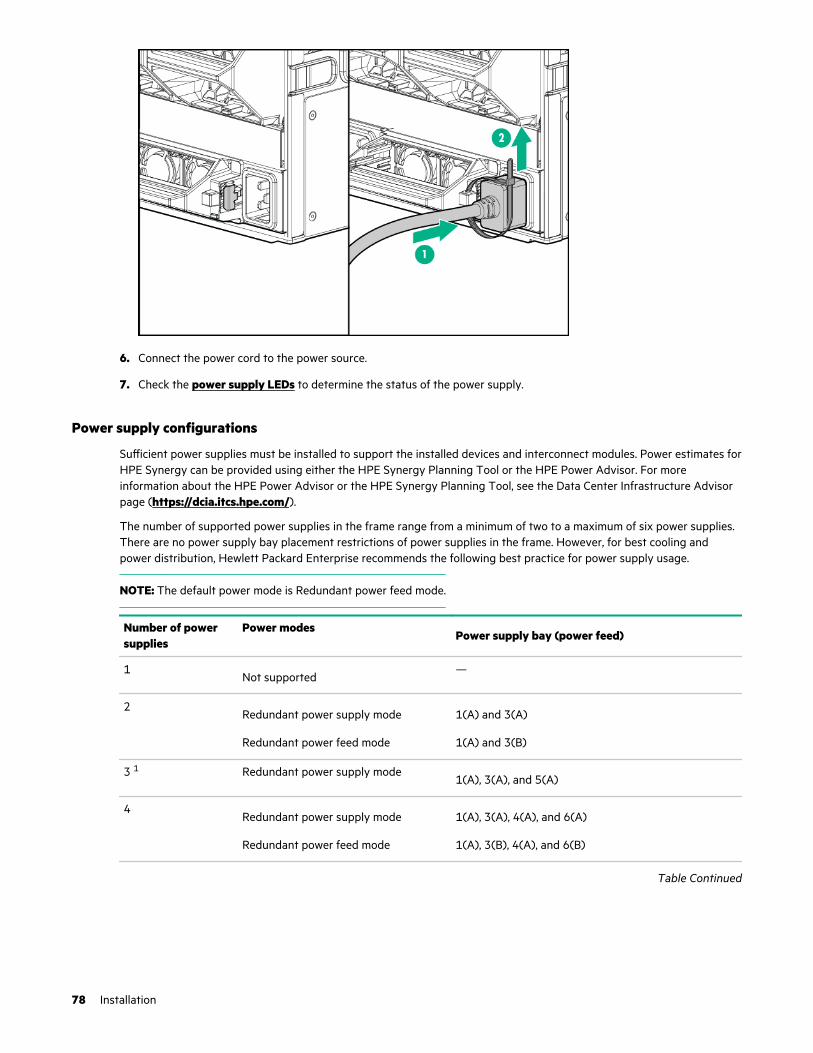
6. Connect the power cord to the power source.
7. Check the power supply LEDs to determine the status of the power supply.
Power supply configurations
Sufficient power supplies must be installed to support the installed devices and interconnect modules. Power estimates forHPE Synergy can be provided using either the HPE Synergy Planning Tool or the HPE Power Advisor. For moreinformation about the HPE Power Advisor or the HPE Synergy Planning Tool, see the Data Center Infrastructure Advisorpage (https://dcia.itcs.hpe.com/).
The number of supported power supplies in the frame range from a minimum of two to a maximum of six power supplies.There are no power supply bay placement restrictions of power supplies in the frame. However, for best cooling andpower distribution, Hewlett Packard Enterprise recommends the following best practice for power supply usage.
NOTE: The default power mode is Redundant power feed mode.
Number of powersupplies
Power modesPower supply bay (power feed)
1Not supported
—
2Redundant power supply mode
Redundant power feed mode
1(A) and 3(A)
1(A) and 3(B)
3 1 Redundant power supply mode1(A), 3(A), and 5(A)
4Redundant power supply mode
Redundant power feed mode
1(A), 3(A), 4(A), and 6(A)
1(A), 3(B), 4(A), and 6(B)
Table Continued
78 Installation

Number of powersupplies
Power modesPower supply bay (power feed)
5 1Redundant power supply mode 1(A), 2(A), 3(A), 4(A), and 6(A)
6Redundant power supply mode
Redundant power feed mode
1(A), 2(A), 3(A), 4(A), 5(A), and 6(A)
1(A), 2(A), 3(B), 4(A), 5(B), and 6(B)
1 If an odd number of power supplies are installed in a frame that is configured for redundant power feed mode, all power supplies areproviding power to the frame, but the capacity of the odd power supply is not used to determine the overall power capacity of theframe.
To enhance cooling, populate all power supply bays with either a power supply blank or a power supply.
Power supply configuration recommendations for the frame do not depend on the type of power supply being used.However, all power supplies must be of the same type. Mixed-type power supply configurations are not supported.
Installing a DC power supply
WARNING: To reduce the risk of electric shock, be sure that the cable grounding kit is properly installed andconnected to a suitable protective earth terminal before connecting the power source to the frame.
Two lugs ship in the kit with the -48V DC power supply. The two-hole lug specification is as follows:
• Width – 0.41 in (10.41 mm)
• Bolt hole size – 0.20 in (5.08 mm)
• Hole spacing – 0.63 in (16.00 mm)
Prerequisites
• Be sure the -48V DC power cables are installed. For more information, see the HPE Synergy 12000 Frame -48V DCPower Cable Installation Instructions.
• Be sure that a ground connection to the HPE Synergy 12000 Frame has been properly installed. See Installing the DCpower grounding kit or the document that ships with the kit.
• Gather the following tools:
◦ Torx T-25 screwdriver
◦ Crimper
Procedure
1. Place the power supply on a flat, level surface.
2. Open the input connector on the new power supply by lifting the input connector cover.
3. Crimp a two-hole lug onto the -48V DC cable.
4. Insert the two-hole lug through the aperture labeled "-48V" on the power supply input connector.
5. Secure the two-hole lug to the -48V DC input connector terminal with two screws.
Installation 79

6. Using a torque-controlled T-25 screwdriver, tighten both screws to 15 lb-in of torque.
7. Crimp a two-hole lug onto the return cable.
8. Insert the two-hole lug through the aperture labeled "RTN" on the power supply input connector.
9. Secure the two-hole lug to the RTN input connector terminal with two screws.
10. Using a torque-controlled T-25 screwdriver, tighten both screws to 15 lb-in of torque.
11. Close the input connector cover.
12. Remove the output connector cover from the new power supply.
80 Installation
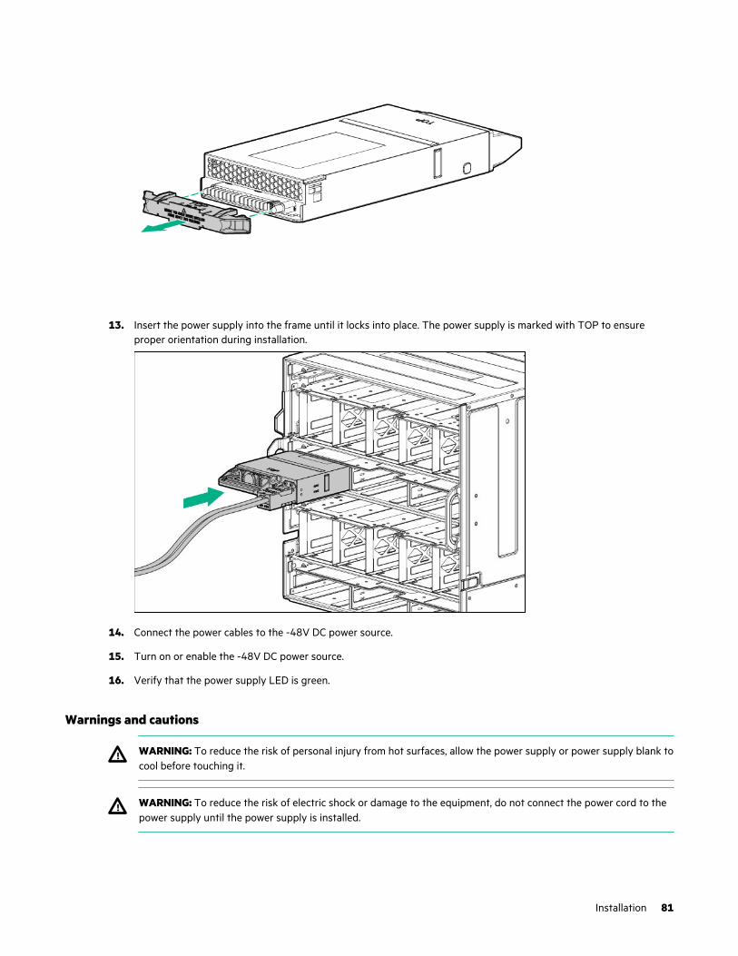
13. Insert the power supply into the frame until it locks into place. The power supply is marked with TOP to ensureproper orientation during installation.
14. Connect the power cables to the -48V DC power source.
15. Turn on or enable the -48V DC power source.
16. Verify that the power supply LED is green.
Warnings and cautions
WARNING: To reduce the risk of personal injury from hot surfaces, allow the power supply or power supply blank tocool before touching it.
WARNING: To reduce the risk of electric shock or damage to the equipment, do not connect the power cord to thepower supply until the power supply is installed.
Installation 81
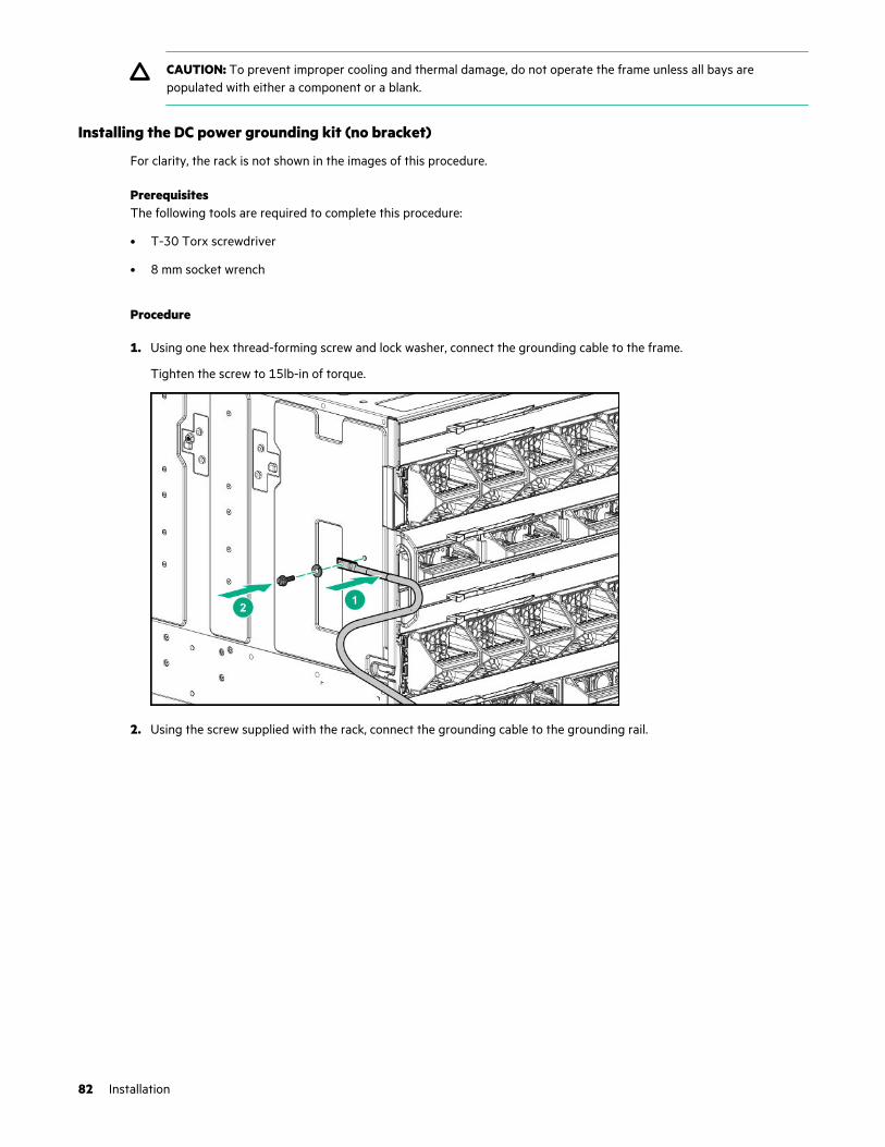
CAUTION: To prevent improper cooling and thermal damage, do not operate the frame unless all bays arepopulated with either a component or a blank.
Installing the DC power grounding kit (no bracket)
For clarity, the rack is not shown in the images of this procedure.
PrerequisitesThe following tools are required to complete this procedure:
• T-30 Torx screwdriver
• 8 mm socket wrench
Procedure
1. Using one hex thread-forming screw and lock washer, connect the grounding cable to the frame.
Tighten the screw to 15lb-in of torque.
2. Using the screw supplied with the rack, connect the grounding cable to the grounding rail.
82 Installation
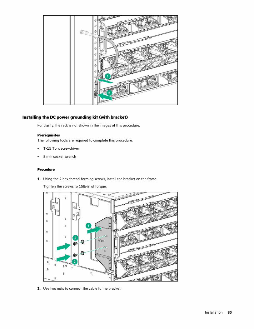
Installing the DC power grounding kit (with bracket)
For clarity, the rack is not shown in the images of this procedure.
PrerequisitesThe following tools are required to complete this procedure:
• T-15 Torx screwdriver
• 8 mm socket wrench
Procedure
1. Using the 2 hex thread-forming screws, install the bracket on the frame.
Tighten the screws to 15lb-in of torque.
2. Use two nuts to connect the cable to the bracket.
Installation 83
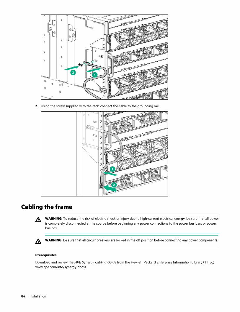
3. Using the screw supplied with the rack, connect the cable to the grounding rail.
Cabling the frame
WARNING: To reduce the risk of electric shock or injury due to high-current electrical energy, be sure that all poweris completely disconnected at the source before beginning any power connections to the power bus bars or powerbus box.
WARNING: Be sure that all circuit breakers are locked in the off position before connecting any power components.
Prerequisites
Download and review the HPE Synergy Cabling Guide from the Hewlett Packard Enterprise Information Library ( http://www.hpe.com/info/synergy-docs).
84 Installation

Procedure
1. Cable the management network ports (MGMT and LINK).
2. Cable the HPE Synergy Image Streamer management ports.
3. Cable the interconnect modules.
4. Connect the power cables. Connect to the power source in your facility to each of the installed power supplies, andpower up the frame.
5. To configure HPE Synergy, connect to the HPE Synergy Console.
Installation 85

HPE Synergy Cabling
Depending on your HPE Synergy configuration, HPE Synergy requires various types of cabling. To assist with planningand cabling HPE Synergy, the HPE Synergy Cabling Guide provides cabling scenarios and diagrams.
• Management network cabling
Cabling the management network includes cabling the frame link module LINK ports together to form a managementring (frame link topology) and cabling two frame link module MGMT ports to the management network.
• HPE Synergy Image Streamer cabling
Cabling for HPE Synergy Image Streamer OS deployment includes management cabling, HPE Synergy Image Streamercabling, and interconnect cabling. HPE Synergy 12000 frames with HPE Synergy Image Streamer installed use eachMGMT port in the frame for OS deployment. When HPE Synergy Image Streamer is installed in a frame, the MGMTports are automatically dedicated to OS deployment and cannot be used for management network connectivity.
• Interconnect module cabling
HPE Synergy supports a composable fabric that spans multiple frames and includes master interconnect modules(switches) and satellite modules (links).
• Power cabling
HPE Synergy power cabling includes cabling multiple frames for power feed redundant power, cabling power suppliesfor power feed redundancy, and power cabling for both a single frame and multiple frame configurations.
• HPE Synergy Console cabling
Direct connections to the HPE Synergy Console are possible by connecting a laptop directly to a frame through thefront panel or by connecting KVM to the frame link module.
For more information, see the HPE Synergy Cabling Guide at the Hewlett Packard Enterprise website (http://www.hpe.com/info/synergy-cabling-guide).
86 HPE Synergy Cabling

Configuring HPE Synergy
Configuration overview
Prerequisites
Before you begin configuring the frame, you should have completed the following steps:
• Installed the frame into the rack.
• Installed all components into the frame.
• Completed the HPE Synergy cabling required for your configuration.
Procedure
1. Setup the management network.
a. Connect to the HPE Synergy Console.
b. Run hardware setup.
c. Remotely connect to HPE OneView.
d. Configure the Network Time Protocol.
e. Add the IP and subnet address ranges.
2. Configure the hardware in HPE OneView.
a. Create a network.
b. Create a logical interconnect group.
c. Define an enclosure group.
d. Create a logical enclosure.
e. Create a server profile.
3. Update the firmware.
a. Update the HPE Synergy appliance module firmware.
b. Add a firmware bundle to the appliance module firmware repository.
4. Configure HPE Synergy Image Streamer.
For more information, see "Quick Start: Initial configuration of HPE Synergy Image Streamer" in the HPE OneView Helpfor HPE Synergy at http://www.hpe.com/info/synergy-docs.
5. Configure additional settings.
For more information, see "Quick Start: Initial configuration of HPE OneView" in the HPE OneView Help for HPESynergy at http://www.hpe.com/info/synergy-docs.
More information
HPE Synergy Console connections on page 88
Configuring HPE Synergy 87
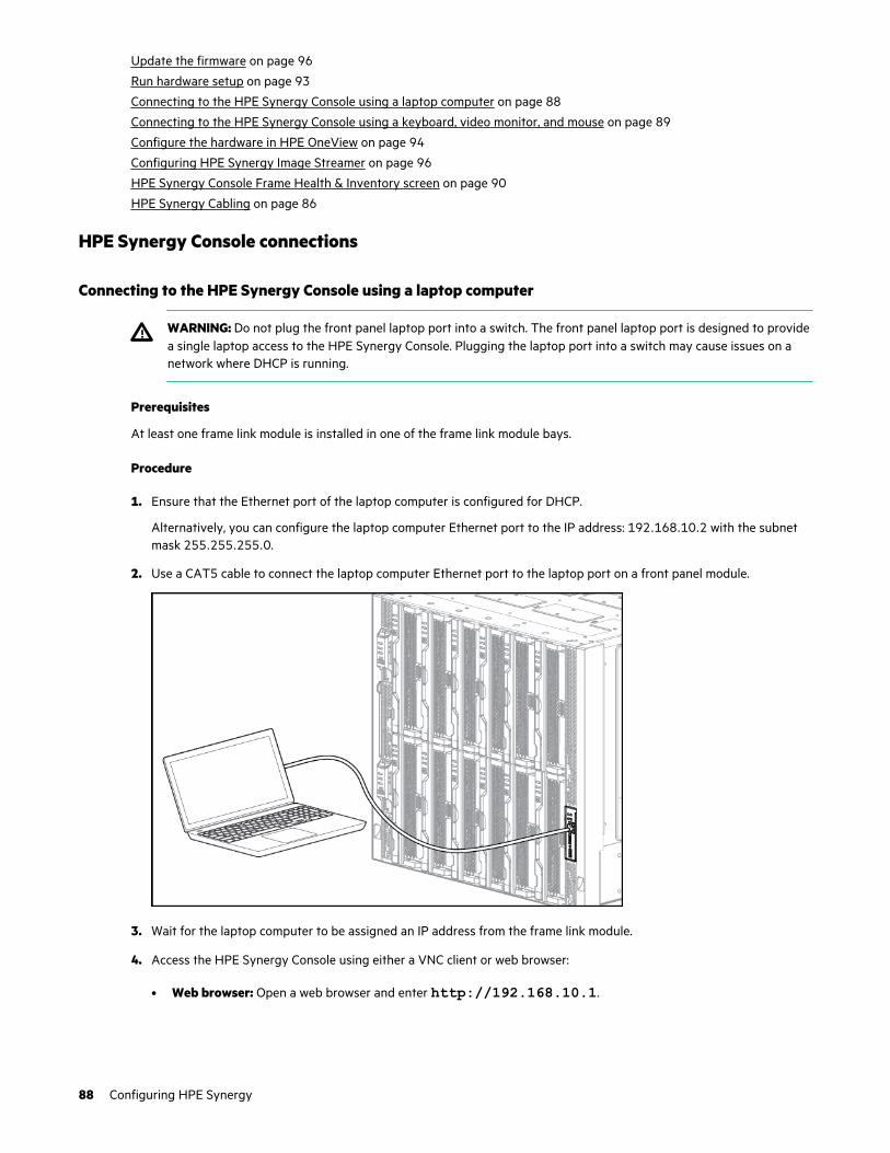
Update the firmware on page 96
Run hardware setup on page 93
Connecting to the HPE Synergy Console using a laptop computer on page 88
Connecting to the HPE Synergy Console using a keyboard, video monitor, and mouse on page 89
Configure the hardware in HPE OneView on page 94
Configuring HPE Synergy Image Streamer on page 96
HPE Synergy Console Frame Health & Inventory screen on page 90
HPE Synergy Cabling on page 86
HPE Synergy Console connections
Connecting to the HPE Synergy Console using a laptop computer
WARNING: Do not plug the front panel laptop port into a switch. The front panel laptop port is designed to providea single laptop access to the HPE Synergy Console. Plugging the laptop port into a switch may cause issues on anetwork where DHCP is running.
Prerequisites
At least one frame link module is installed in one of the frame link module bays.
Procedure
1. Ensure that the Ethernet port of the laptop computer is configured for DHCP.
Alternatively, you can configure the laptop computer Ethernet port to the IP address: 192.168.10.2 with the subnetmask 255.255.255.0.
2. Use a CAT5 cable to connect the laptop computer Ethernet port to the laptop port on a front panel module.
3. Wait for the laptop computer to be assigned an IP address from the frame link module.
4. Access the HPE Synergy Console using either a VNC client or web browser:
• Web browser: Open a web browser and enter http://192.168.10.1.
88 Configuring HPE Synergy

Alternatively, you can include the legacy port number.
http://192.168.10.1:5800• VNC client: Open a VNC client and connect to 192.168.10.1 port 5900.
A VNC client will load to the web browser and open the HPE Synergy Console.
Connecting to the HPE Synergy Console using a keyboard, video monitor, and mouse
NOTE: This procedure describes connecting a keyboard and mouse to a monitor with an integrated USB hub.Alternatively, you can use a standalone USB hub to connect a keyboard and mouse.
NOTE: Cabling to an HPE Synergy 4-Port Frame Link Modules requires an HPE Synergy 4-Port Frame Link Module USBAdapter
Prerequisites
A frame link module is installed in a frame link module bay.
Procedure
1. Connect a monitor cable to the monitor port and connect a USB cable to the USB port on either:
• The front panel module on the front of the frame.
• Either frame link module on the rear of the frame.
Configuring HPE Synergy 89

• An HPE Synergy 4-Port Frame Link Module USB Adapter connected to an HPE Synergy 4-Port Frame Linkmodule.
2. Connect a monitor to the frame with the monitor cable.
3. Connect a USB keyboard and mouse to the USB ports on the monitor, and connect the monitor USB to the frame withthe USB cable.
Alternatively, connect the USB keyboard and mouse to a USB hub connected to the frame.
HPE Synergy Console Frame Health & Inventory screen
The Frame Health & Inventory screen displays the health status of all components in a frame.
90 Configuring HPE Synergy

Configuring HPE Synergy 91

Item Description
1 Navigation menu - Breadcrumb navigation menu.
2 Frame Health - Provides the overall frame health status.
Statuses include:
• OK
• Warning
• Critical
3Information - Provides detailed frame information including name, serialnumber, power information, ambient temperature, maintenance console status,and the number of active HPE Synergy Console sessions.
4Maintenance Console - Indicates whether FLM Maintenance Console access isenabled or disabled. Indicates whether a maintenance console password hasbeen set (configured) in HPE OneView to further restrict unauthorized access.
5Frame Management Network - Provides the network address associated withthe Active frame link module. This network address is used to manage the frameand is independent of the frame link module-specific addresses.
NOTE: When adding remote frames (enclosures) to HPE OneView, use this linklocal IPv6 address.
6Frame Link Module Ports - Displays the frame link module MGMT and LINKport information for the Active and Standby frame link modules.
7Thermal Subsystem - Displays the frame ambient temperature and detailed fanspeed data including which device is driving the fan speed for each fan.
8FLM Certificates - Displays the frame link module certificates and public keys.
9Frame rear view - Displays the components installed in the rear of the frameand the health status of each component. Each component can be clicked toview individual component health and information screens.
Health statuses include:
• Green: OK
• Yellow: Warning
• Red: Critical
Table Continued
92 Configuring HPE Synergy
Item Description
10Frame front view - Displays the components installed in the front of the frameand the health status of each component. Each component can be clicked toview individual component health and information screens.
Health status include:
• Green: OK
• Yellow: Warning
• Red: Critical
11 Actions menu - Provides access to management and diagnostic actions.
12 Help screen - Provides a description of the HPE Synergy Console icons andaccess to the frame link module end-user license agreement.
Run hardware setup
Procedure
1. From the HPE Synergy Console, click Connect to start HPE OneView.
2. To connect with install technician user privileges, click Hardware Setup.
To connect as Administrator, select the Administrator access check box.
3. Review the hardware inventory:
NOTE: A spinning icon at the top of the inventory section indicates when HPE OneView is bringing the enclosures andthe devices within them under management. Devices might not be listed until the discovery process is complete.
a. Wait for HPE OneView to complete the add operation.
b. Confirm that the inventory includes all installed components.
c. For any hardware not discovered by HPE OneView, look for problems with frame link module cabling, hardware notfully inserted, or other hardware issues.
4. Review and correct any issues listed in the Hardware Setup Checklist:
a. To troubleshoot all issues, follow corrective actions in HPE OneView.
b. Return to the Hardware Setup screen and look for additional issues until the Checklist indicates Setup complete.
For more information about using HPE OneView, see the online help by clicking the question mark on the top bar ofthe HPE Synergy Console.
5. (Optional) Select Edit networking from the Hardware Setup screen.
Edit the HPE OneView networking settings and click OK. The Maintenance IP address fields are required unless youhave disabled service console access.
6. To add a remote enclosure, select Actions > Add remote enclosures from the Hardware Setup screen.
Enter the IPv6 address of a frame link module that is connected to a frame in the remote frame link topology. Theremote frame link topology must be in the same subnet as the primary frame link topology.
Configuring HPE Synergy 93
7. Unmanaged interconnect modules require console access for initial setup. Click the Actions menu on the top bar ofthe HPE Synergy Console and select the module from the Serial Consoles > Interconnects menu.
a. Press the Enter key to begin the serial console session with that interconnect module.
b. Configure the interconnect module using the instructions provided with the interconnect module.
c. To close the session, click the X in the top right corner.
NOTE: To access the serial console for an interconnect module, connect to the HPE Synergy Console through ports inthe same frame as the interconnect module.
For more information, see the procedures for connecting to the HPE Synergy Console.
8. Log out from the HPE OneView Hardware Setup session.
To close the session, click the X in the top right corner of the Synergy console.
After hardware setup is complete, the system is ready to be configured for a production environment. An HPEOneView administrator can perform configuration tasks with an account that provides additional user privileges.
For more information about HPE OneView administration, see the HPE OneView online help or the HPE OneView UserGuide for Synergy.
Remotely connect to HPE OneViewAfter Hardware Setup is complete, you can log in to HPE OneView remotely to complete configuration.
• IP Address: Use the Link-Local IP Address on the HPE Synergy Console.
• Username: Administrator• Password (default): admin
Configure Network Time ProtocolEnter the IP address of one or more network time servers (NTP).
In a clustered appliance, both the active appliance and the standby appliance must be able to receive updates from thetime server. If the time server cannot reach the appliance, updating the time does not occur and the appliance generatesan alert.
To add NTP servers, go to OneView > SETTINGS > Time and Local.
Add IP and subnet address rangesEnter IPv4 address requirements for management network connection to HPE iLOs and interconnects. If present in theHPE Synergy network, add HPE Synergy Image Streamer IPv4 addresses.
For more information, see "About configuring IP addresses in an enclosure group" and "About ID pools" in the HPEOneView Help for HPE Synergy.
To add IP Address ranges, go to OneView > SETTINGS > Edit Addresses and Identifiers > Edit.
Configure the hardware in HPE OneViewThe steps in this section provide an overview of the initial setup of HPE OneView.
94 Configuring HPE Synergy
For detailed steps, see "Quick Start: Initial configuration of HPE OneView" in the HPE OneView Help for HPE Synergy(http://www.hpe.com/support/OV-InitialConfig).
Create a network
IMPORTANT: Define a SAN Manager before creating an FC or FCoE network.
Create networks to define connections that route data across the IT infrastructure. You can create a single Ethernet , FibreChannel, or FCoE network or multiple, tagged Ethernet networks at one time.
Before creating networks, be aware of the networking maximums. For more information, see the HPE OneView SupportMatrix for HPE Synergy on the Hewlett Packard Enterprise Information Library (http://www.hpe.com/info/synergy-docs).
To create a network, go to OneView > NETWORKING > Networks.
Create a logical interconnect group
One or more logical interconnect groups are associated with an enclosure group and are used to define the logicalinterconnect configuration for every enclosure that is using that enclosure group.
To create a logical interconnect group, go to OneView > NETWORKING > Logical Interconnect group.
Define an enclosure group
NOTE: For solutions that include HPE Synergy Image Streamer, create the HPE Image Streamer cluster in DeploymentServers before creating the enclosure group.
NOTE: Uploading a firmware bundle before creating a logical enclosure is recommended. However, you can choose to adda firmware bundle later, in step Add a firmware bundle to the appliance firmware repository.
An enclosure group is a logical resource that defines a consistent configuration for an enclosure or a set of enclosuresmaking up a logical enclosure. The network connectivity for an enclosure group is defined by the logical interconnectgroups associated with the enclosure group.
An enclosure group can contain up to five enclosures.
To add an enclosure group, go to OneView > SERVERS > Enclosure groups.
Create a logical enclosure
After HPE Synergy frames are discovered automatically during hardware setup, you must manually create a logicalenclosure. The logical enclosure must contain the number of HPE Synergy frames that are connected together withinterconnect link cables. For example, if you have three HPE Synergy frames cabled together, create a logical enclosurethat contains all three HPE Synergy frames.
To create a logical interconnect group, go to OneView > SERVERS > Logical enclosure.
Create a server profile
NOTE: Creating a profile requires access to storage. Configure storage before creating a profile or define a local storageconfiguration as part of profile creation.
A server profile is the configuration for a server instance. Server profiles and server profile templates capture the entireserver configuration in one place, enabling you to replicate new server profiles and to modify them to reflect changes inyour data center.
To create a profile, go to OneView > SERVERS > Server Profiles.
Configuring HPE Synergy 95
Update the firmwareAfter setting up your HPE Synergy system, update to the latest HPE Synergy Management combination and HPE SynergyCustom SPP.
Update the HPE Synergy appliance firmware
IMPORTANT: To ensure compatibility, each HPE Synergy Composer installed into an HPE Synergy solution mustbe on the same firmware level. Similarly, each HPE Synergy Image Streamer must be on the same firmware level. Ifthe appliance pair is not on the same firmware level, a reimage of the appliance module with the older firmwarelevel is required.
If both appliance modules in a redundant pair are on the same firmware version, use HPE OneView to update to the latestfirmware version.
For more information about reimaging the appliance firmware, see Validating HPE Synergy appliance firmware: Preparingan HPE Synergy appliance for first-time setup on the Hewlett Packard Enterprise website (http://www.hpe.com/info/synergy-docs).
Add a firmware bundle to the appliance firmware repository
To ensure that your hardware has the latest and most robust firmware bundle that takes advantage of all availablemanagement features, download the latest firmware bundle to your appliance module and add it to the firmwarerepository. For more information, see the HPE Synergy Software Release Overview page (http://www.hpe.com/downloads/synergy) and the HPE Synergy Software Release Information site (http://www.hpe.com/info/synergy-sw-release-information).
To add a firmware bundle, go to OneView > APPLIANCE > Firmware Bundles.
Configure HPE Synergy Image StreamerIf your solution includes HPE Synergy Image Streamers, additional configuration steps are required. See Quick Start: Initialconfiguration of HPE Synergy Image Streamer in the HPE OneView Help for HPE Synergy (www.hpe.com/support/OV-InitialConfig-IS).
Configuring HPE Synergy Image Streamer
HPE Synergy Image Streamer can be used to deploy OS build artifacts to the Synergy compute modules. However, it mustbe installed and configured within HPE OneView.
Procedure
1. Create a management network that is consistent with the HPE OneView management network.
2. Add an IPv4 subnet and address range.
Define the range of IPv4 addresses and subnets to set aside for each Image Streamer appliance in the frame linktopology, plus the number of operating system servers expected to be deployed.
3. Add an OS deployment server for use in HPE OneView to deploy operating systems to managed servers.
4. Create a deployment network to enable operating system deployment to servers using Image Streamer.
5. Create one or more logical interconnect groups to define the connections between Image Streamer appliances and theservers they will support.
6. Create an enclosure group that includes the Image Streamer configuration.
7. Create a logical enclosure to define the set of frames to which to apply the Image Streamer enclosure group.
96 Configuring HPE Synergy
For more information about configuring HPE Image Streamer, see the HPE OneView online help or the HPE OneView UserGuide on the Hewlett Packard Enterprise website (http://www.hpe.com/info/synergy-docs).
Configuring HPE OneView to deploy OS build artifacts to compute modules
Once you add an Image Streamer OS deployment server in HPE OneView, you can launch the Image Streamer graphicaluser interface from the HPE OneView OS Deployment Servers screen.
Procedure
1. Upload artifacts from a bundle or create new artifacts.
From the Image Streamer interface, the software administrator can upload artifacts from a bundle for use in HPEOneView or use the Image Streamer interface to create golden images and other OS build artifacts.
2. Create or configure a server profile.
Create and apply a server profile which includes an OS deployment selection and values for the server-specific settingsfor the selected OS deployment.
3. Verify operating system deployment.
Review server profile screen details to view the operating system volume that has been created as a result ofdeployment.
4. Power on the compute module.
Power on server to boot from deployed operating system.
For more information about using Image Streamer to create and deploy OS build artifacts, see the Image Streamer onlinehelp or the HPE Image Streamer User Guide on the Hewlett Packard Enterprise website (http://www.hpe.com/info/synergy-docs).
Configure additional settingsOnce your HPE Synergy system is setup, configure additional settings. For detailed steps, see "Quick Start: Initialconfiguration of HPE OneView" in the HPE OneView Help for HPE Synergy (http://www.hpe.com/support/OV-InitialConfig).
Configuring HPE Synergy 97

Troubleshooting
Symbols on equipmentThe following symbols might be found on the equipment to indicate the presence of potentially hazardous conditions.
This symbol indicates the presence of hazardous energy circuits or electric shock hazards. Refer allservicing to qualified personnel.
WARNING: To reduce the risk of injury from electric shock hazards, do not open this enclosure.Refer all maintenance, upgrades, and servicing to qualified personnel.
This symbol indicates the presence of electric shock hazards. The area contains no user or fieldserviceable parts. Do not open for any reason.
WARNING: To reduce the risk of injury from electric shock hazards, do not open this enclosure.
This symbol on an RJ-45 receptacle indicates a network interface connection.
WARNING: To reduce the risk of electric shock, fire, or damage to the equipment, do not plugtelephone or telecommunications connectors into this receptacle.
This symbol indicates the presence of a hot surface or hot component. If this surface is contacted,the potential for injury exists.
WARNING: To reduce the risk of injury from a hot component, allow the surface to cool beforetouching.
249.50 kg
550.00 lb
This symbol indicates that the component exceeds the recommended weight for one individual tohandle safely.
WARNING: To reduce the risk of personal injury or damage to the equipment, observe localoccupational health and safety requirements and guidelines for manual material handling.
These symbols, on power supplies or systems, indicate that the equipment is supplied by multiplesources of power.
WARNING: To reduce the risk of injury from electric shock, remove all power cords to disconnectpower from the system completely.
Error screens when connecting to the HPE Synergy ConsoleThe following are some basic errors screens that may be encountered when connecting to the HPE Synergy Console.
HPE Synergy Console not respondingIf the frame Composers are detected but not responding after 20 minutes, the following Attention screen appears, andprompts a Reset.
98 Troubleshooting

Select Reset. HPE OneView resets and attempts again to boot the frame Composers.
Troubleshooting 99

Frame not claimed by an HPE Synergy ConsoleWhen the frame is not claimed by an HPE Synergy Console, the following Attention screen appears.
To resolve, connect to the front panel display of a frame that contains an HPE Synergy Console.
The HPE Synergy Console cannot connect to HPE OneViewIf the HPE Synergy Console cannot connect to HPE OneView, the following Attention screen appears.
100 Troubleshooting
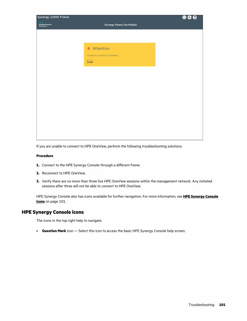
If you are unable to connect to HPE OneView, perform the following troubleshooting solutions.
Procedure
1. Connect to the HPE Synergy Console through a different frame.
2. Reconnect to HPE OneView.
3. Verify there are no more than three live HPE OneView sessions within the management network. Any initiatedsessions after three will not be able to connect to HPE OneView.
HPE Synergy Console also has icons available for further navigation. For more information, see HPE Synergy Consoleicons on page 101.
HPE Synergy Console iconsThe icons in the top right help to navigate.
• Question Mark icon — Select this icon to access the basic HPE Synergy Console help screen.
Troubleshooting 101
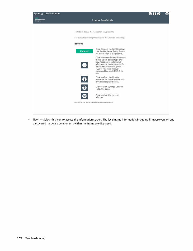
• i icon — Select this icon to access the Information screen. The local frame information, including firmware version anddiscovered hardware components within the frame are displayed.
102 Troubleshooting

• Screen icon — Select this icon to access the hardware components discovered by the HPE Synergy Console, includingAppliances, Interconnects, and Devices. Empty bays are represented by the grayed out "—" symbol, and componentsthat are discovered but not managed by a serial port are grayed out and disabled.
Troubleshooting 103

• Serial console — To access the serial console:
1. Select one of the hardware components from the Screen icon to access the serial console for that component.
104 Troubleshooting
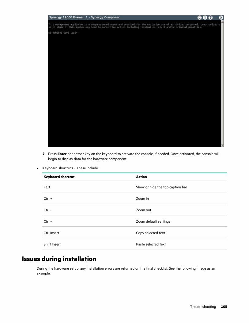
2. Press Enter or another key on the keyboard to activate the console, if needed. Once activated, the console willbegin to display data for the hardware component.
• Keyboard shortcuts - These include:
Keyboard shortcut Action
F10 Show or hide the top caption bar
Ctrl + Zoom in
Ctrl - Zoom out
Ctrl = Zoom default settings
Ctrl Insert Copy selected text
Shift Insert Paste selected text
Issues during installationDuring the hardware setup, any installation errors are returned on the final checklist. See the following image as anexample:
Troubleshooting 105

• —Indicates a critical error that must be corrected.
• —Indicates a warning that can be corrected, but is not mandatory. For hardware issues, this warning could meanthat redundancy has been lost and additional failures would cause a loss of service.
To correct the errors that appear, select the hyperlink to the right of the suggested corrective action, and then follow anyadditional steps suggested on the screen.
HPE Synergy ConsoleWhen the HPE OneView user interface cannot be accessed, the HPE Synergy Console is available from a direct connectionto the frame. The functions available in the console might require specific user credentials.
The HPE Synergy Console provides users the ability to troubleshoot issues within the frame and complete regularmaintenance on the installed appliances. From the HPE Synergy Console, you can:
• View appliance details.
• Restart or shutdown an appliance.
• Activate an offline appliance.
• Create a support dump file.
• Reset the appliance password.
• Perform a factory reset of the appliance.
• Launch service console.
106 Troubleshooting

For more information, see the HPE Synergy Frame Link Module User Guide on the Hewlett Packard Enterprise website(http://www.hpe.com/info/synergy-docs).
Accessing the HPE OneView Maintenance Console from the frame link module
Procedure
1. Connect locally to the HPE Synergy Console.
2. Select the Screen icon at the top right of the page.
3. Select an HPE Synergy Composer from the Appliances menu.
A blank text window appears.
4. Press Enter.
5. At the login prompt, log in using the following username:
maintenanceThe HPE OneView Maintenance Console opens.
For additional instructions on using the HPE OneView Maintenance Console, see the HPE OneView User Guide for HPESynergy on the Hewlett Packard Enterprise website.
Connecting to the HPE OneView maintenance console using SSH
NOTE: Hewlett Packard Enterprise recommends the use the following tools for accessing the HPE OneView maintenanceconsole through an SSH connection:
• PuTTY
• MTPuTTY
Procedure
1. Open one of the recommended tools on your local computer.
2. Access the appliance by specifying its fully qualified domain name or its IP address.
3. Enter the following user name at the login prompt:
maintenance4. Log in to the HPE OneView maintenance console.
5. Provide the local administrator credentials when prompted.
Creating a support dump fileThis procedure describes how to use the HPE Synergy maintenance console to create a support dump file from the localappliance (the appliance on which the HPE Synergy maintenance console runs) and store it on a USB drive.
If the local appliance is the active appliance in an appliance cluster and if the standby appliance is reachable, the supportdump contains the data for both cluster members. Otherwise, a support dump is created with data for the local applianceonly.
The support dump file is encrypted by default.
Troubleshooting 107

CAUTION: Creating the support dump file overwrites any existing backup file on the appliance. If possible, refrainfrom creating a support dump if you have not copied the backup file to an external location for safekeeping.
Prerequisites
• Minimum required privileges: Infrastructure administrator
• Use a USB 2.0 or 3.0 device drive, formatted as an NTFS or FAT32 file system and with only one partition. Ifnecessary, use a computer to format the USB drive.
• The USB drive must have enough free space (typically 1 GB to 4 GB) to store the support dump file.
Creating a support dump file from the HPE Synergy maintenance console
Procedure
1. Ensure that the USB drive is installed in the USB port of the local appliance.
IMPORTANT: Do not remove the USB drive until the operation is complete and the Synergy maintenanceconsole advises that it is safe to remove the drive.
2. Use the appliance console to access the HPE Synergy maintenance console main menu.
3. Select Support dump.
A new set of commands appears.
4. Do one of the following:
• Select Create support dump to create a support dump and copy it to the USB drive.
• Select Download existing support dump to copy a support dump from the appliance to the USB drive.
5. Wait until the support dump file is copied. There is a message on the screen stating that the support dump wassuccessfully completed and that it is safe to remove the USB drive.
Resetting to factory settingsIn the event that you need to reset settings to their original factory status, the following options are available:
• Resetting the appliance module to the original factory settings on page 108
• Performing a frame link module factory reset on page 111
Resetting the appliance module to the original factory settingsA factory reset restores the appliance to the original factory settings. It does not change the installed firmware version.
You have the option of preserving or erasing the appliance network settings. A factory reset with preserved networksettings is necessary for recovering an appliance module from an unrecoverable error state. This option clears most faultsso that you can restore the appliance module from a backup file. The reset option does not change the cryptographymode.
You might need to reset the appliance module either to decommission it (so that you can migrate the hardware) or toreturn the appliance to a known state for reuse (for example, to restore the appliance from a backup file).
108 Troubleshooting

CAUTION:
• This action erases appliance data including logs.
This action erases appliance data including logs and managed device settings in HPE OneView.
This action does not affect the configuration of managed devices in any way. Therefore, manual clean-up ofdevices might be required if HPE OneView will no longer manage them.
• REST API calls and GUI operations are not allowed during the reset action.
• The Preserve network settings option does not change the cryptography mode. Verify that the cryptographymode is set to the desired mode from Settings > Security, and review the Cryptography settings.
• If the HPE Synergy Console does not return to a normal state with factory setting, it might be necessary toreimage the appliance.
NOTE:
• In an appliance cluster, the standby appliance module must be removed from the cluster before resetting the activeappliance. Removing the standby appliance module resets it to factory settings and shuts it down.
• If you intend to restore the Composer settings from a backup file after it the Composer is reset or reimaged, and thatbackup file contains the management configuration for the enclosures, you do not need to reset all managed frames totheir factory settings.
• If you intend to re-import and manage the Synergy frames, you must perform these actions:
1. Reset the HPE OneView appliance to its factory settings.
2. Then, reset each frame managed by that Composer to their factory settings.
Resetting an HPE Synergy frame to factory defaults also removes the networking configuration on theinterconnects in those frames, which disrupts workloads running on compute modules in those frames.
• If you do not have a backup file for HPE OneView, you will need to perform a factory reset on all the devices in thedomain.
Prerequisites
• Minimum required privileges: Infrastructure administrator
• Ensure that all tasks have been completed or stopped, and that all other users are logged off.
• When resetting or reimaging a Composer to a factory-fresh state, you must also reset each frame managed by thatComposer to their factory-fresh state. However, if you intend to restore the Composer settings from a backup after itis reset or reimaged, you do not need to reset each frame.
IMPORTANT: To reset the whole system to a factory-fresh state, you must also perform a factory reset on eachframe in the domain.
If you intend to restore the system from a backup file, you do not need to perform a factory reset of each frame.Restoring the system from the backup file restores each frame to management.
• Ensure that all tasks have been completed or stopped, and that all other users are logged off.
Procedure
1. If you are decommissioning the appliance and its managed environment, remove all hardware from HPE OneViewmanagement, for example:
Troubleshooting 109

• Delete or un-assign all server profiles.
• Delete all logical enclosures.
• Delete any storage volumes allocated within HPE OneView.
• Reset managed devices (configured through IP address pools) to default IP addressing
2. From the main menu, select Settings, and then click Appliance.
3. Select Actions > Factory Reset.
4. Optionally select Preserve appliance network settings to erase the appliance data without losing networkconnectivity, for example, to rebuild the appliance.
5. Select OK.
6. Select the appropriate option:
• Reset to factory defaults while preserving appliance module network settings—Use this option to erase theappliance module data without losing network connectivity, for example, for rebuilding the appliance module.
• Full appliance factory reset to defaults—Use this option to prepare a system when returning or discardingappliance module hardware, or when completely reusing a new appliance module with new communicationsettings.
IMPORTANT: This option can cause you to lose your network connection to the appliance module.Therefore, you must access the appliance module using its IPv6 link local address.
This action displays a progress bar while it is running. Logins are disabled automatically. When the appliance resetis completed after several minutes, you can log in and set up your appliance module as you did for the first time.
7. If you are decommissioning the appliance, ensure that all hardware managed by HPE OneView is removed frommanagement.
This action displays a progress bar while it is running. Logins are disabled automatically. When the appliance module resetis completed after several minutes, you can log in and set up your appliance module as you did for the first time.
Frame link module factory reset
IMPORTANT: When a frame is configured and is actively managed by HPE OneView, a factory reset should only beperformed when required by a recommended HPE OneView management or service process.
The Factory Reset action resets all frame link modules in a frame to factory default settings. Resetting a frame link moduleto factory default settings will take the frame link module offline for up to 10 minutes. If the frame link module is installedin a frame managed by HPE OneView, the frame link module will be reclaimed by HPE OneView after the factory reset iscomplete.
Some instances where a factory reset may be necessary include:
• Prior to moving a frame to a new HPE OneView environment.
• After performing a factory reset of the HPE Synergy Composer that manages the frame.
For more information, see the HPE OneView for Synergy User Guide on the Hewlett Packard Enterprise InformationLibrary (http://www.hpe.com/info/synergy-docs).
110 Troubleshooting
Performing a frame link module factory reset
NOTE: This procedure only factory resets the frame link modules installed in the frame. It does not factory reset any othercomponents installed in the frame.
NOTE: The frame link module can be factory reset by pressing the front panel reset button until the front panel UIDflashes or by using the HPE Synergy Console Actions menu. Hewlett Packard Enterprise recommends using the HPESynergy Console to perform a factory reset.
Procedure
1. Connect to the HPE Synergy Console.
2. Select Actions > FLM Diagnostics > Factory Reset.
3. Click Yes, reset.
Troubleshooting 111
HPE Synergy documentation resources
The Hewlett Packard Enterprise Information Library (https://www.hpe.com/info/synergy-docs) provides acomprehensive, one stop location for all HPE Synergy documentation, including installation instructions, user guides,maintenance and service guides, best practices, and links to additional resources. The Library supports filtering toimprove findability.
Document: Provides:
HPE Synergy Solution
Start Here Poster First-time setup procedure of an HPE Synergy solution, from hardwareinstallation to HPE OneView configuration.
Release Notes Release descriptions, new features, documentation updates, and issues andsuggested actions for products like HPE Synergy, HPE Synergy ImageStreamer, and HPE OneView.
Migration Guide Information about migrating from HPE Synergy Composer to HPE SynergyComposer2 and from HPE Synergy Frame Link Module to HPE Synergy 4-port Frame Link Module.
Validating HPE Synergy appliancefirmware: Preparing an HPE Synergyappliance for first-time setup
Procedures for preparing an HPE Synergy appliance for initial use in asystem.
Appliances User Guide Outlines appliance module management, configuration, and security.
Cabling Guide Cabling examples for management network, HPE Synergy Image Streamer,interconnects, and power.
Configuration and Compatibility Guide An overview of HPE Synergy management and fabric architecture, detailedhardware component identification, and configuration requirements forhardware components.
Frame Link Module User Guide Management, configuration, and security information for the HPE Synergy 4-Port Frame Link Module, HPE Synergy Frame Link Module, and HPE SynergyManagement Console.
Power Management Overview Guide Additional details on how HPE Synergy manages power usage in an HPESynergy 12000 Frame.
Troubleshooting Guide Information for resolving common problems and courses of action for faultisolation and identification, issue resolution, and maintenance.
Error Message Guide Information for resolving issues associated with specific error messages.
Documentation Map A descriptive map to filter and locate the HPE Synergy documentation youneed.
Glossary Terminology, descriptions, and drawings to provide an understanding of theproduct and to help familiarize with the HPE Synergy ecosystem.
HPE Synergy Image Streamer
Deployment workflow Interactively describes the various steps involved in setting up HPE SynergyImage Streamer for OS deployment and has pointers to the differentdocuments that contain detailed instructions on the steps.
Table Continued
112 HPE Synergy documentation resources
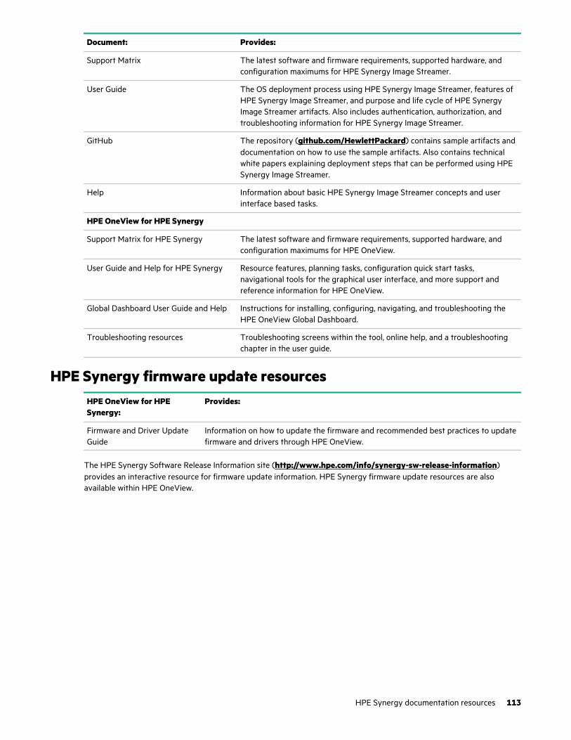
Document: Provides:
Support Matrix The latest software and firmware requirements, supported hardware, andconfiguration maximums for HPE Synergy Image Streamer.
User Guide The OS deployment process using HPE Synergy Image Streamer, features ofHPE Synergy Image Streamer, and purpose and life cycle of HPE SynergyImage Streamer artifacts. Also includes authentication, authorization, andtroubleshooting information for HPE Synergy Image Streamer.
GitHub The repository (github.com/HewlettPackard) contains sample artifacts anddocumentation on how to use the sample artifacts. Also contains technicalwhite papers explaining deployment steps that can be performed using HPESynergy Image Streamer.
Help Information about basic HPE Synergy Image Streamer concepts and userinterface based tasks.
HPE OneView for HPE Synergy
Support Matrix for HPE Synergy The latest software and firmware requirements, supported hardware, andconfiguration maximums for HPE OneView.
User Guide and Help for HPE Synergy Resource features, planning tasks, configuration quick start tasks,navigational tools for the graphical user interface, and more support andreference information for HPE OneView.
Global Dashboard User Guide and Help Instructions for installing, configuring, navigating, and troubleshooting theHPE OneView Global Dashboard.
Troubleshooting resources Troubleshooting screens within the tool, online help, and a troubleshootingchapter in the user guide.
HPE Synergy firmware update resourcesHPE OneView for HPESynergy:
Provides:
Firmware and Driver UpdateGuide
Information on how to update the firmware and recommended best practices to updatefirmware and drivers through HPE OneView.
The HPE Synergy Software Release Information site (http://www.hpe.com/info/synergy-sw-release-information)provides an interactive resource for firmware update information. HPE Synergy firmware update resources are alsoavailable within HPE OneView.
HPE Synergy documentation resources 113

Figure 7: HPE Synergy Software Release Information
HPE Synergy SoftwareRelease Information site:
Provides:
Firmware Comparison Tool A list of HPE Synergy Management Combinations to use to compare HPE SynergyCustom SPPs supported by the selected HPE Synergy Management Combination.
Firmware Feature Table A list of firmware features to use to compare HPE Synergy Custom SPPs supported bythe selected HPE Synergy Management Combination.
Upgrade Paths Table Information on HPE Synergy Composer and HPE Synergy Image Streamer upgradepaths and HPE Synergy Management Combinations.
VMware OS Support Information and requirements for using the VMware vSphere OS with HPE SynergyCustom SPPs.
114 HPE Synergy documentation resources

HPE Synergy document overview (documentationmap)
www.hpe.com/info/synergy-docs
Planning
• HPE Synergy Migration Guide
• HPE Synergy 12000 Frame Site Planning Guide
• HPE Synergy Configuration and CompatibilityGuide
• HPE OneView Support Matrix for HPE Synergy
• HPE Synergy Image Streamer Support Matrix
• Setup Overview for HPE Synergy
• HPE Synergy Software Overview Guide
Installing hardware
• HPE Synergy Start Here Poster (included withframe)
• HPE Synergy 12000 Frame Setup and InstallationGuide
• Rack Rails Installation Instructions for the HPESynergy 12000 Frame (included with frame)
• HPE Synergy 12000 Frame Rack Template(included with frame)
• Hood labels
• User guides
• HPE Synergy Cabling Guide
• HPE OneView Help for HPE Synergy — Hardwaresetup
Configuring for managing and monitoring
• HPE OneView Help for HPE Synergy
• HPE OneView User Guide for HPE Synergy
• HPE OneView API Reference for HPE Synergy
• User Guides
• HPE Synergy Software Release Information site
Managing
• HPE OneView User Guide for HPE Synergy
• HPE Synergy Image Streamer Help
• HPE Synergy Image Streamer User Guide
• HPE Synergy Image Streamer API Reference
• HPE Synergy Image Streamer deployment workflow
• HPE Synergy Frame Link Module User Guide
Monitoring
• HPE OneView User Guide for HPE Synergy
• HPE OneView Global Dashboard User Guide
Maintaining
• Product maintenance and service guides
• HPE OneView for HPE Synergy Firmware and Driver UpdateGuide
• HPE OneView Help for HPE Synergy
• HPE OneView User Guide for HPE Synergy
• HPE Synergy Appliances Maintenance and Service Guide
Troubleshooting
• HPE OneView alert details
• HPE Synergy Troubleshooting Guide
• Error Message Guide for HPE ProLiant Gen10 servers andHPE Synergy
• Integrated Management Log Messages and TroubleshootingGuide for HPE ProLiant Gen10 and HPE Synergy
• HPE OneView API Reference for HPE Synergy
• HPE Synergy Image Streamer API Reference
HPE Synergy document overview (documentation map) 115

Specifications
HPE Synergy QuickSpecsHPE Synergy has system specifications as well as individual product and component specifications. For completespecification information, see the HPE Synergy and individual HPE Synergy product QuickSpecs on the Hewlett PackardEnterprise website (www.hpe.com/info/qs).
116 Specifications
Electrostatic discharge
Be aware of the precautions you must follow when setting up the system or handling components. A discharge of staticelectricity from a finger or other conductor may damage system boards or other static-sensitive devices. This type ofdamage may reduce the life expectancy of the system or component.
To prevent electrostatic damage:
• Avoid hand contact by transporting and storing products in static-safe containers.
• Keep electrostatic-sensitive parts in their containers until they arrive at static-free workstations.
• Place parts on a grounded surface before removing them from their containers.
• Avoid touching pins, leads, or circuitry.
• Always be properly grounded when touching a static-sensitive component or assembly. Use one or more of thefollowing methods when handling or installing electrostatic-sensitive parts:
◦ Use a wrist strap connected by a ground cord to a grounded workstation or computer chassis. Wrist straps areflexible straps with a minimum of 1 megohm ±10 percent resistance in the ground cords. To provide properground, wear the strap snug against the skin.
◦ Use heel straps, toe straps, or boot straps at standing workstations. Wear the straps on both feet when standingon conductive floors or dissipating floor mats.
◦ Use conductive field service tools.
◦ Use a portable field service kit with a folding static-dissipating work mat.
If you do not have any of the suggested equipment for proper grounding, have an authorized reseller install the part.
For more information on static electricity or assistance with product installation, contact an authorized reseller.
Electrostatic discharge 117
Support and other resources
Accessing Hewlett Packard Enterprise Support
• For live assistance, go to the Contact Hewlett Packard Enterprise Worldwide website:
http://www.hpe.com/info/assistance
• To access documentation and support services, go to the Hewlett Packard Enterprise Support Center website:
http://www.hpe.com/support/hpesc
Information to collect
• Technical support registration number (if applicable)
• Product name, model or version, and serial number
• Operating system name and version
• Firmware version
• Error messages
• Product-specific reports and logs
• Add-on products or components
• Third-party products or components
Accessing updates
• Some software products provide a mechanism for accessing software updates through the product interface. Reviewyour product documentation to identify the recommended software update method.
• To download product updates:
Hewlett Packard Enterprise Support Center
www.hpe.com/support/hpesc
Hewlett Packard Enterprise Support Center: Software downloads
www.hpe.com/support/downloads
Software Depot
www.hpe.com/support/softwaredepot
• To subscribe to eNewsletters and alerts:
www.hpe.com/support/e-updates
• To view and update your entitlements, and to link your contracts and warranties with your profile, go to the HewlettPackard Enterprise Support Center More Information on Access to Support Materials page:
www.hpe.com/support/AccessToSupportMaterials
IMPORTANT: Access to some updates might require product entitlement when accessed through the HewlettPackard Enterprise Support Center. You must have an HPE Passport set up with relevant entitlements.
118 Support and other resources

Customer self repairHewlett Packard Enterprise customer self repair (CSR) programs allow you to repair your product. If a CSR part needs tobe replaced, it will be shipped directly to you so that you can install it at your convenience. Some parts do not qualify forCSR. Your Hewlett Packard Enterprise authorized service provider will determine whether a repair can be accomplished byCSR.
For more information about CSR, contact your local service provider or go to the CSR website:
http://www.hpe.com/support/selfrepair
Remote supportRemote support is available with supported devices as part of your warranty or contractual support agreement. Itprovides intelligent event diagnosis, and automatic, secure submission of hardware event notifications to Hewlett PackardEnterprise, which will initiate a fast and accurate resolution based on your product's service level. Hewlett PackardEnterprise strongly recommends that you register your device for remote support.
If your product includes additional remote support details, use search to locate that information.
Remote support and Proactive Care information
HPE Get Connected
www.hpe.com/services/getconnected
HPE Proactive Care services
www.hpe.com/services/proactivecare
HPE Datacenter Care services
www.hpe.com/services/datacentercare
HPE Proactive Care service: Supported products list
www.hpe.com/services/proactivecaresupportedproducts
HPE Proactive Care advanced service: Supported products list
www.hpe.com/services/proactivecareadvancedsupportedproducts
Proactive Care customer information
Proactive Care central
www.hpe.com/services/proactivecarecentral
Proactive Care service activation
www.hpe.com/services/proactivecarecentralgetstarted
Warranty informationTo view the warranty information for your product, see the links provided below:
HPE ProLiant and IA-32 Servers and Options
www.hpe.com/support/ProLiantServers-Warranties
HPE Enterprise and Cloudline Servers
www.hpe.com/support/EnterpriseServers-Warranties
HPE Storage Products
www.hpe.com/support/Storage-Warranties
HPE Networking Products
www.hpe.com/support/Networking-Warranties
Support and other resources 119

Regulatory informationTo view the regulatory information for your product, view the Safety and Compliance Information for Server, Storage,Power, Networking, and Rack Products, available at the Hewlett Packard Enterprise Support Center:
www.hpe.com/support/Safety-Compliance-EnterpriseProducts
Additional regulatory information
Hewlett Packard Enterprise is committed to providing our customers with information about the chemical substances inour products as needed to comply with legal requirements such as REACH (Regulation EC No 1907/2006 of the EuropeanParliament and the Council). A chemical information report for this product can be found at:
www.hpe.com/info/reach
For Hewlett Packard Enterprise product environmental and safety information and compliance data, including RoHS andREACH, see:
www.hpe.com/info/ecodata
For Hewlett Packard Enterprise environmental information, including company programs, product recycling, and energyefficiency, see:
www.hpe.com/info/environment
Documentation feedbackHewlett Packard Enterprise is committed to providing documentation that meets your needs. To help us improve thedocumentation, send any errors, suggestions, or comments to Documentation Feedback ([email protected]). Whensubmitting your feedback, include the document title, part number, edition, and publication date located on the frontcover of the document. For online help content, include the product name, product version, help edition, and publicationdate located on the legal notices page.
120 Support and other resources

Acronyms and abbreviations
CSA
Canadian Standards Association
CSR
Customer Self Repair
DHCP
Dynamic Host Configuration Protocol
ESD
electrostatic discharge
IEC
International Electrotechnical Commission
iLO
Integrated Lights-Out
iLO 4
Integrated Lights-Out 4
PCIe
Peripheral Component Interconnect Express
PDU
power distribution unit
RETMA
Radio Electronics Television Manufacturers Association (rack spacing)
RoHS
Restriction of Hazardous Substances
SAS
serial attached SCSI
TMRA
recommended ambient operating temperature
UID
unit identification
UPS
uninterruptible power system
USB
universal serial bus
Acronyms and abbreviations 121