How to Prevent Li-Ion Battery Failures
117
Transcript of How to Prevent Li-Ion Battery Failures

How to Prevent Li-Ion Battery Failures
Vidyu Challa PhD
Technical director DfR Solutions
2
o Samsung 2016 Root Cause Analysis
o Battery failure mechanisms and modes ndash pathway to thermal runaway
o Battery protection mechanismso Internal and External
o Mitigation methodso Design
o Manufacturing
o Battery Management System
o Application Assembly and Storage
o User
o Summary
OUTLINE
3
o Anode negative electrode cathode positive electrode
o Lithium ion is an intercalation battery (lsquorocking chair
mechanismrsquo)
o insert between layers or in crystal structure
Li Ion Battery Working Mechanism
4
o Solid electrolyte interphase (SEI) formed during first few
charging cycles
o SEI can be unstable outside operating window
Solid Electrolyte Interphase
5
Graphite Anode SEI Organic Electrolyte
6
Samsung 2016 Battery Failures
6
Source Samsung Galaxy Note 7 failure investigation press conference Jan 2017 All Information in public domain
o Galaxy Note 7 fires were reported within a few weeks of the product launch
o Samsung recalled affected phones and pointed to a manufacturing error from its battery supplier Samsung SDI
o The batteries were swapped with ones from its Chinese supplier ATL
o Replacement phones that were supposed to be ldquofixedrdquo also started to catch on fire
o Samsung scrapped the entire product line 25 million phone recalls prior Cost Samsung $5 Billion
Samsung Galaxy 2016 Failures
7
Flattened Jellyroll Pouch Cell Design
8
o Damage to the negative electrode windings caused by
deflection by a pouch design that did not provide sufficient
volume to accommodate the electrode assembly
o Curvature of pouch causes deflection of the negative electrodes
Manufacturer A Root Cause
9
o Negative electrode damage provides multiple pathways to cell internal short circuit and thermal runaway under normal cycling conditions
o Damage to the separator
o Lithium plating
Negative Electrode Deflection
10
Source Information in public domain
Overcrowded Bus Analogy
11
o Tab welding defect created an internal short
Manufacturer B Root Cause
12
o Poorly controlled
welding process - Burr
height 80 microm in some
cases
o Normal swelling and
contraction occurs
during charge-
discharge cycling
o Some batteries were missing the insulation tape
o Samsung blames the flaws on its factories trying to get production started too quickly to counteract lost sales
o There are simply no short cuts when it comes to lithium ion battery manufacturing process control
Manufacturer B Root Cause
13
14
LITHIUM ION BATTERY
FAILURE MODES AND
MECHANISMS
14
LITHIUM ION BATTERY FAILURE MODES
15
Lithium Ion Battery Failures
Non-energetic
Failures Energetic Failures
Explosion
IR
Increase
Permanent
Safety Feature
Enabled
Cell
swelling
Electrolyte
leakage
Capacity
Loss
Fire Venting
o All non-energetic failures are not benign
o What dictates whether a failure is energetic or not
o Same initiating fault can have different outcomes
o Depends on whether the initiating fault can create a self-
sustaining exothermic reaction
BENIGN ENERGETIC AND NON-ENERGETIC
16
LITHIUM ION BATTERY FAILURE CAUSE
17
Elevated Cell
Temperature
Heat
Dissipatedgt
Heat
Generated
Heat
Dissipatedlt
Heat
Generated
Non-
energetic
Failures
Thermal
runaway
Overcharge
Overdischarge
High ambient temp
External short circuit
Internal short
circuit
Metallic ContaminationBurrsweld
defects
Lithium PlatingMechanical
damage
Low
Anodecathode
ratio
Anode delam
Low electrolyte
OutcomeCauseMitigation
Safety
electronics
and cell
internal
safety
features
Manufacturing
quality and
process control
Low temp
charging
Design
o Breakdown of passivating SEI layer on anode
o Excessive currents overcharging or high external ambient temp
o Starts at 80 C New SEI formed but at a higher uncontrolled rate in an
exothermic reaction Self accelerating reaction
o Electrolyte breakdown
o Organics in the electrolyte break down releasing flammable hydrocarbon
gases but no oxygen
o Typically around 110 -120 C
o Pressure starts to build up Even
if temp rises above flash point
no burning due to lack of oxygen
CELL REACTIONS AT ELEVATED TEMP -1
18
o Safety vent pops to prevent explosion (18650 metal can type) ndashnow have oxygen available
o Separator melting occurs around 155 C causing electrodes to short
o Further temperature rise causes metal oxide breakdown at cathode releasing oxygen in an exothermic reaction For Cobalt oxide this happens at 200 C
o Highly flammable organics elevated temp and oxygen
CELL REACTIONS AT ELEVATED TEMP -2
19
o Elevated temperature and cell failure are intricately tied together
o Elevated temperature negatively impacts capacity
o At higher rates higher capacity degradation
o 50 Loss in cycle life from 1 C to 12 C charging rate
o Cannot be explained by temperature rise alone
ELEVATED TEMP AND FAILURES
20
Choi S S amp Lim H S (2002) Factors that affect cycle-life and
possible degradation mechanisms of a Li-ion cell based on LiCoO2
Journal of Power Sources 111(1) 130-136
o Rapid performance degradation (sudden death) ndash lithium plating is highly reactive to electrolyte
o electrolyte and lithium consumption causing electrode dry out
o further lowering of anode to cathode ratio
o increased impedance and further risk of plating
o Safety issues ndash risk of dendritic growth exothermic reaction between plated lithium and electrolyte
LITHIUM PLATING ndash WHY IS IT BAD
21
Image source Safety of Lithium-Ion Batteries
Zhang et al Lithium-Ion Batteries
Advances and Applications
2014 Pages 409ndash435
o When does it happeno Operation outside specification window- overcharging high charging rate low temperature
(protection circuitry)
o Batteryapplication design ndash low anodecathode low electrolyte mechanical deformation from product (design engineeringquality)
o Manufacturing defects ndash eg anode delamination mechanical deformation poor quality cells (quality engineering)
LITHIUM PLATING
22
Image Source Understanding
undesirable anode lithium
plating issues in lithium-ion
batteries Liu et al RSC Adv
20166
LITHIUM ION SAFETY
23
Abuse Manufacturing Defects
Cell amp Application Design
Handling
Thermal Abuse
Electrical Abuse
Mechanical Abuse
2 90 5 3
bull BMS amp Circuitrybull Standardized Tests
Fiel
d F
ailu
re
Mit
igat
ion
Val
Fa
ilure
Cau
ses
Nea
r M
iss
Even
ts
0 50 25 25
Internal Shorts Cell Design
Application design
Storage
Assembly into host device
bull Quality Process Control
bull CT scansManuf audit
bull Design reviewsbull CT ScansApp
specific testing
bull Process and procedure review
bull Self discharge tests
User
24
Internal Shorts ndash lsquoSoft underbellyrsquo
Internal shorts are typically the result of manufacturing defects
and are not effectively mitigated by safety systems
There is no good internal short circuit test that effectively
screens out these defects
The best defense is to have sound manufacturing process
controls
24
25
Improper BMS Design
o Poorly designed BMS and use of improper chargers are
responsible for some of the spectacular field failures
o Over-voltage failures are more spectacular and immediate than
grown in manufacturing defects which can take time to manifest
themselves
o Battery protection system includes the charger circuitry
protection circuit module located at the battery and is
optimized for a specific cell chemistry and application
o Good BMS design should include use of a custom connector so that
everyday USB chargers canrsquot be plugged in and allowed to abuse the
cell
26
LITHIUM ION CELL
MANUFACTURING PROCESS
26
27
o Incoming raw materials
o Electrode fabrication and cell assembly
o Environmental control
MANUFACTURING CONTROLS
28
o Energy density
o Pack as much active material as possible
o Minimize fines which make wetting difficult and require more
solvent and lower the solids content in slurry
o Power density
o Higher void volumes lower
electrode pressed density
and thickness
POWER DENSITY VS ENERGY DENSITY
29
o Incoming powders ndash Tap density particle size distribution
(PSD) surface area purity
o Binders and binder solvents
o Separator
o Electrolyte
o Current collectors
o Dry room storage (dew point of at least -40 C) Dew point is
used to express water vapor concentration at this level because
the corresponding relative humidity value is less than 1
MANUFACTURING INCOMING RAW MATERIALS
Separator
ELECTRODE FABRICATION
30
QC -Viscosity and
dispersion control
Riskndash shorts unreacted
lumps cause risk of
dryout and plating
QC ndashthickness slurry
metering
Riskndash non-uniform
coating leading to
shorting risk dryout
QC ndash thickness
adhesion
Riskndash blisters lack of
adhesion leading to
lithium plating
QC ndash electrode
thickness oncehr roller
gap check 4-6 hrs
porosity Riskndashlack of
cell performance for
energy or power
QC ndashburr control
tension control cutting
wheel maintenance
Riskndashinternal shorts
CELL ASSEMBLY FORMATION AND TESTING
Battery Manufacturing (nd) Retrieved March 22 2017 from httpw3siemenscommarketsglobalenbattery-
manufacturingapplicationsprocesspagesdefaultaspx
WindingStacking
QC ndashalignment
Riskndashinternal shorts
Tab welding
QC ndash burrweld height
control
Risk ndash internal shorts
QC ndash Weight before and
after stringent moisture
control
Risk ndash electrode dryout and
plating swelling from
moisture
QC ndash OCV IR weight
dimension check prior to
formation Rest to allow
electrolyte wetting after
filling followed by
formation
QC ndash OCV IR weight
dimension followed by
aging qualification tests
32
o The process involves a multi-zone oven with low temperatures for the first zone higher temperatures for the middle zone followed by a lower temperature for the final zone
o Specific temperatures will depend on binder chemistry and on slurry properties
o For PVDF binder on the cathode the recommended drying oven temperature profile for a 5-zone oven is as follows zone 1 ndash 75-90 degC zones 2-4 ndash 125-130 deg C zone 5 ndashapproximately 75 deg C A 4-zone oven should run at slower speed to allow more solvent evaporation
DRYING TEMPERATURES
33
o Incoming materials control
o Internal specifications that identify minimize and control all known
and likely impurities in incoming materials
o Internal specifications that control material properties or specs
o Ability to track changes in vendor materials
GENERAL MANUFACTURING GUIDELINES
34
o Manufacturing process control
o Safety critical equipment must be identified - process of verifying
equipment operation periodically Preventive maintenance plan
implementation
o Procedures to avoid metal contamination throughout the manufacturing
process
o Processes to collect loose material such as coating dust
o A method of detecting mechanical damage to electrodes in the
manufacturing process such as an automated vision system
o Statistical process control (SPC) to monitor maximum particle size slurry
viscosities coating weight calendered thickness weight of electrolyte
dispensed cell weight open circuit voltage (OCV) and capacity
GENERAL MANUFACTURING GUIDELINES
35
o Robust environmental control with a specific focus keeping ambient moisture minimized
o Destabilizes SEI layer and electrolyte and causes gassing
ENVIRONMENTAL CONTROL
36
LITHIUM ION CELL DESIGN
GUIDELINES
36
37
o Anode should overhang cathode by 05 mm or more on all sides for stacked cell or along top and bottom ends for jellyroll (min of 01 mm per IEEE 16251725)
o Anode should have higher electrochemical capacity than cathode by 10-15
o Example 1 g anode specific capacity is 350 mAhg So total anode capacity is 350 mAh
o 1 g cathode with specific capacity of 280 mAhg has total capacity of 280 mAh
Cathode shall never put out more lithium
ions than the anode can accommodate
CELL DESIGN GUIDELINES
Cathode
Separator
Anode
38
o Separator overhangs anode on all sides (room temperature to
at least 110 C- IEEE 16251725)
o Less than 5 shrinkage in both machine and transverse
directions at 90 C as a minimum
o Separator should have sufficient mechanical
strength to withstand cell assembly operations
CELL DESIGN GUIDELINES
Cathode
Separator
Anode
39
o Product design ndash make sure there is enough room for battery to
expand as it goes through charge ndashdischarge cycles Recommend 10
margin
o Pay particular attention to corners
o Poor manufacturing can reduce design margin
o Cutting operation variability
o Pick and place variability
CELL DESIGN GUIDELINES
40
ARTICLE QUALITY ASESSMENT
CELL CT SCANS AND
TEARDOWN
40
41
o Deep discharged cell
ARTICLE QUALITY ASESSMENT ndash CT SCANS
42
o Exercise - Describe what you see
o Electrode alignment is good on right image
o Variability in jellyroll winding on left and middle images
o Insufficient anode overlap in center of middle image
ARTICLE QUALITY ASESSMENT- CT SCANS
43
o Conduct CT scans and cell teardowns on a handful of units
o What to look for in CT scans
o Uniform cell winding or stacking
o No particulates
o No significant electrode delamination
o Anodes should overhang cathode by 05 mm ideally but a minimum
of 01 mm on each side
o No excessive deformation at pouch corners
o Cutting operationpick and place variability
PHYSICAL ARTICLE QUALITY ASESSMENT ndash CT SCANS
44
o Look at a few electrode pieces using optical microscopy
and SEMEDS
ARTICLE QUALITY ASESSMENT ndash TEARDOWNS
45
LITHIUM ION INTERNAL
AND EXTERNAL
PROTECTION SYSTEMS
45
o Positive Temperature Coefficient (PTC) device - inhibit high current surges
o Charge interrupt device (CID)- opens the electrical path if an excessively high charge voltage raises the internal cell pressure to a threshold value
o Safety vent- allows a controlled release of gas in the event of a rapid increase in cell pressure
o Hot electrolyte vapors and gas will always blow towards the burst disc instead of splitting the sides
o Shutdown Separators
CELL SAFETY PROTECTION MECHANISMS
46
o PTC - doughnut shaped device that sits between two metal
plates and is made of a polymeric material
o At high currents or temperatures resistance of the PTC increases
sharply causing the current to drop
PTC DEVICE
47
Image source nasagov
o The PTC is resettable and reverts
back after the fault is removed
o Once activated it subsequently
activates at a lower current and
temperature
o Works by releasing the connection at the positive terminal and
opening the electrical path
o Pressure valve which will disable the cell permanently of
pressure in the cell is too high
o Is not resettable
CHARGE INTERRUPT DEVICE
48
Image source nasagov
o Pouch cells do not have an internal CID PTC or safety vent
o Can have PTC or fuse elements in series with cell
POUCH CELL PROTECTION
49
Image source nasagov
50
o Separator is usually made of polyethylene (PE) polypropylene (PP) or a combination of the two
o Inner PE layer shuts down at 130degC by closing the pores the outer PP layers do not melt until reaching 155degC
SHUTDOWN SEPARATOR
Image Source Battery University
51
o Separator should increase its resistance by two orders of
magnitude at shutdown temperature (typically 130 C)
SHUTDOWN CURVES
Image Source Arora and Zhang Battery Separators Chem Rev 2004 104 (10) pp 4419ndash4462
52
o Know separator propertieso Thickness
o single vs multiple layer (PE PP or combination)
o ceramic coated or not
o Ceramic coatings can enhance thermal stability and prevent separator collapse till 200 C and beyond
o Ceramic coated separators usually may not have the mechanical strength to withstand winding and assembly- irrelevant for prismatic or stacked designs
SHUTDOWN SEPARATOR PROPERTIES
Impedance (1 kHz AC) vs Shutdown temperature of electrolyte soaked separators (ab) Polyethylene and (c)
polypropylene
53
BATTERY MANAGEMENT
SYSTEM (BMS) AND
PROTECTION CIRCUITRY
53
54
o Operating outside of specifications
Operating Outside Specifications
Image source Electropaedia
55
o Depends on a number of factors
o State of charge (SOC)
o Ambient temperature
o Cell chemistry
o Cell design
o Most severe thermal runaway occurs in an overcharged state
o Case temperatures can reach 600 C
o High temperatures are driven by exothermic reactions of the electrodes and the electrolyte
Severity of Thermal Runaway
56
o Self heating temperature o Fully charged 18650 cells brought to self heating temperature
(70 to 90 C) in adiabatic environment go into thermal runaway in 2 days
o Fully charged 18650 in adiabatic environment brought to 150 C (with separator melting) will run away in minutes
o UL standard requires fully charged cells to withstand 4 hour storage at 75 C and 10 min storage at 130 C
o IEEE standard requires 1 hour exposure at 130 C
o Overcharge o Charging a 42 V system to 5 V will almost certainly cause
immediate thermal runaway
Thermal Runaway Initiation ndash Some Numbers
57
o EV electric bus caught fire in Shenzhen China during
charging
o BMS Failure
o Without a BMS there is no
safe lithium ion battery
EV Bus Failure
58
o Consist of charger and a battery protection printed circuit board (PCB)
o Also called a battery protection circuit module (PCM)
o Important functions of protection systems include monitoring controlling and terminating charge and discharge as needed
o Failure of protection circuitry to either sense or respond to an out of range condition causes battery failure
ELECTRONIC PROTECTION SYSTEMS
59
o Maintain cells within operating window and prevent cells
from going into
o Over voltage
o Over current
o Over temperature
o Over discharge
o Balance individual cells to enhance overall capacity
o Disconnect batteries in a safe way in emergency situations
o Predict remaining capacity or state of charge
BMS FUNCTIONS
BMS Webinar httpswwwdfrsolutionscombattery-management-systems-and-safety-and-reliability-webinar
60
o Most obvious failure mode is exceeding specified voltage
o Charging a 42 V system to 5 V will almost certainly cause immediate thermal runaway
o Charging at excess currents
o Overcharge effects
o Anode ndash lithium plating rather than intercalation
o Cathode ndashexcess de-intercalation causes crystal structure to collapse and release heat
o Heat and gas release (both Joule heating and parasitic reactions)
o Electrolyte and electrode decomposition
OVER CHARGE - VOLTAGE
61
o Over voltage may be applied to the battery from a defective charger or due to improper monitoring on a single cell
o Slight overcharge (from minor deviations in voltage monitoring) causes capacity loss rather than direct thermal runaway
o Overvoltage protection can be implemented by opening a charge MOSFET or a fuse
o Overcharge protection is so critical that multiple independent circuits are typically used to prevent single points of failure
OVER VOLTAGE
62
o Hazard from over discharge is highly underestimated
o When a cell goes into deep discharge copper ions from the negative electrode current collector dissolve On recharge copper dendrites can form
o Over discharge can also cause breakdown of the SEI layer and gas formation
OVER DISCHARGE
Image Source Rui Guo1 Languang
Lu1 Minggao Ouyanga1 and Xuning
Feng1 Sci Rep 2016
63
How Does a Battery Go into
Deep Discharge
63
64
o Uncontrolled storage without appropriate recharge
procedures
o Mechanically damaged cells (from electronics impinging
on cell)
OVER DISCHARGE SCENARIOS
65
o Three kinds of discharge occur during storage o PCM sleep current and leakage currents
o Battery self discharge
o Manufacturing quality
o Temp
o State of charge
o Device sleep currents
o At 3 V (or other threshold cutoff) load is disconnected although above lsquoconsumption currentsrsquo are active
o At deep discharge cutoff value of 2 V (or other manufacturer specified value) PCM and device sleep currents are turned off but battery self discharge continues
Discharge During Storage
66
o Lithium ion self discharge around 1-2 per month + a
few cent for PCM
o High SOC and temperatures degrade storage life (and
cycle life)
o Rule of thumb ndash 10 C increase in temperature doubles self
discharge rate
o Store at conditions close to 25 C and 40 SOC
Battery Self Discharge
67
o To keep the contamination as low as possible to reduce
leakage current de-ionized water wash should be used
in the board cleaning process
o Verify the board cleanliness to make sure the levels of
contamination is low
o Investigate if humidity is an issue and that conformal
needs to be used
PCM (BMS) Self Discharge
68
o Have a pre-check charging function on batteries where deep discharge cutoff voltage was reached Charger circuit checks if a deeply discharged battery is reaches a threshold value in give time Otherwise considered a lsquodamagedrsquo battery
o Mitigating hazard from copper shunts
o Proper battery storage and recharge procedures
o Minimize PCM leakage currents
o Ensure cell quality
o Prevent cell mechanical damage
Deep Discharge Checklist
69
o Over current can causeo Degradation in cycle life
o Thermal runaway
o Threshold limits for current are functions of both current and time Protection circuit system can use different combinations of time and current to produce a fault Example - high currentshort time or lower currentlong time
o Some faults are recoverable such as when a MOSFET is turned on and others are non-recoverable such as when a fuse is ignited
o Causes of over-current could be a defective charger or due to an internal short
OVER CURRENT PROTECTIONS
70
o A good battery management system will limit charge current and voltage at high and low temperature extremes per Japan Electronics and Information Technology Industries Association (JEITA) guidelines
OVER CURRENT
(60 degC)
CoolCold Warm Hot
(0 degC)
Reduce charging
current andor
voltage
Reduce charging
current andor
voltage
71
o Current limits are incorporated into the protection
circuits located in pack or device
o Circuits monitor current in and out of battery and open up
MOSFET to interrupt current
o Backup protection usually includes a fuse or PTC placed
in series with battery pack
SHORT CIRCUIT PROTECTION
72
BATTERY LIFE DEGRADATION
AND STORAGE
72
73
o Battery life example
o Nominal capacity is 2900 mAh End of life capacity at 80 of initial capacity is 2300 mAh
o Is this data sufficient to give you a life of 500 cycles
BATTERY LIFE AND AGING ISSUES
74
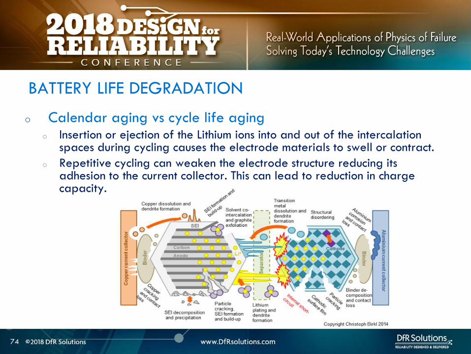
o Calendar aging vs cycle life agingo Insertion or ejection of the Lithium ions into and out of the intercalation
spaces during cycling causes the electrode materials to swell or contract
o Repetitive cycling can weaken the electrode structure reducing its adhesion to the current collector This can lead to reduction in charge capacity
BATTERY LIFE DEGRADATION
75
o Storage degradation high temperature aging causes
growth of the passivating layer
o It consumes lithium and electrolyte and leads to capacity loss
and impedance increase (both capacity and power fade)
Pores can be blocked as a result
o Low rate batteries may not see a big impact
(voltage drop = IR)
BATTERY LIFE DEGRADATION CALENDAR AGING
76
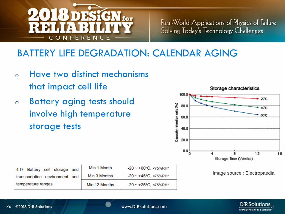
o Have two distinct mechanisms
that impact cell life
o Battery aging tests should
involve high temperature
storage tests
BATTERY LIFE DEGRADATION CALENDAR AGING
Image source Electropaedia
77
o Characterize both reversible and irreversible storage loss
o In this example 25 irreversible and 5 reversible
capacity loss
REVERSIBLE VS IRREVERSIBLE STORAGE LOSS
Assume a = 2900 mAh
d = 70 a = 2030 mAh
e = 95 a = 2700 mAh
a
d
e
78
LITHIUM ION CHEMISTRIES
78
79
o Term Lithium-Ion encompasses many different chemistries
o Anode ndash graphite (Lithium Titanate LTO for very fast charge cells)
o Cathode - Cathodes are lithiated metal oxides or lithiated metal
phosphates
o Lithium Cobalt Oxide (LCO)
o Lithium Iron Phosphate(LFP)
o Nickel Manganese Cobalt (NMC)
o Lithium Manganese Oxide(LMO)
o Cathode chemistry is where you get enhancements in safety
energy and power density
Battery Chemistry
80
o Lithium Cobalt Oxide (LCO) ndash commonly used in consumer electronics
o High energy density
o Low power
o Least safe
o Moderate cycle life
Battery Chemistry
o Lithium Iron Phosphate(LFP) ndashndash automotive power tools UPS e-cigs
o Safest chemistry
o High power density
o Very high cycle life
o Lower voltageLower energy density
o Higher self discharge rate
81
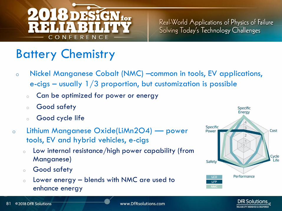
o Nickel Manganese Cobalt (NMC) ndashcommon in tools EV applications
e-cigs ndash usually 13 proportion but customization is possible
o Can be optimized for power or energy
o Good safety
o Good cycle life
Battery Chemistry
o Lithium Manganese Oxide(LiMn2O4) ndashndash power tools EV and hybrid vehicles e-cigs
o Low internal resistancehigh power capability (from Manganese)
o Good safety
o Lower energy ndash blends with NMC are used to enhance energy
82
Battery Chemistry Summary
Chemistry LCO NMC LFP LMO
Nominal Voltage(V) 36-37 36-37 32-32 36-37
Charge Voltage(V) 42 42 35-36 42
Safety Poor Good Highest Good
Cycle Life gt500 gt500 gt1000 gt500
Peak Load current (Best result) 2C
(lt1C)
gt30C
(lt10 C)
gt30C
(lt10 C)
Specific energy (WhKg) 150-250 90-120 100-150
Thermal Runaway Temp (ordmC) 150 210 gt270
Used Since 1991 2003 1999 1996
Designation ICR INR IFR IMR
o Knowing chemistry helps to map out worst case scenario
o For pouch cells look at MSDS
83
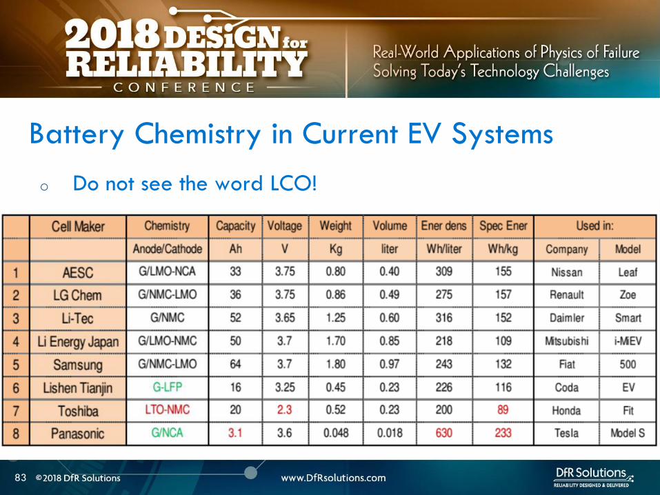
o Do not see the word LCO
Battery Chemistry in Current EV Systems
84
ESTIMATING STORED ENERGY
84
85
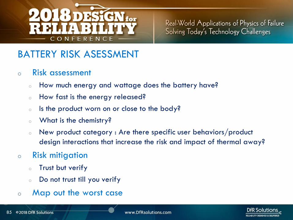
o Risk assessment
o How much energy and wattage does the battery have
o How fast is the energy released
o Is the product worn on or close to the body
o What is the chemistry
o New product category Are there specific user behaviorsproduct
design interactions that increase the risk and impact of thermal away
o Risk mitigation
o Trust but verify
o Do not trust till you verify
o Map out the worst case
BATTERY RISK ASESSMENT
86
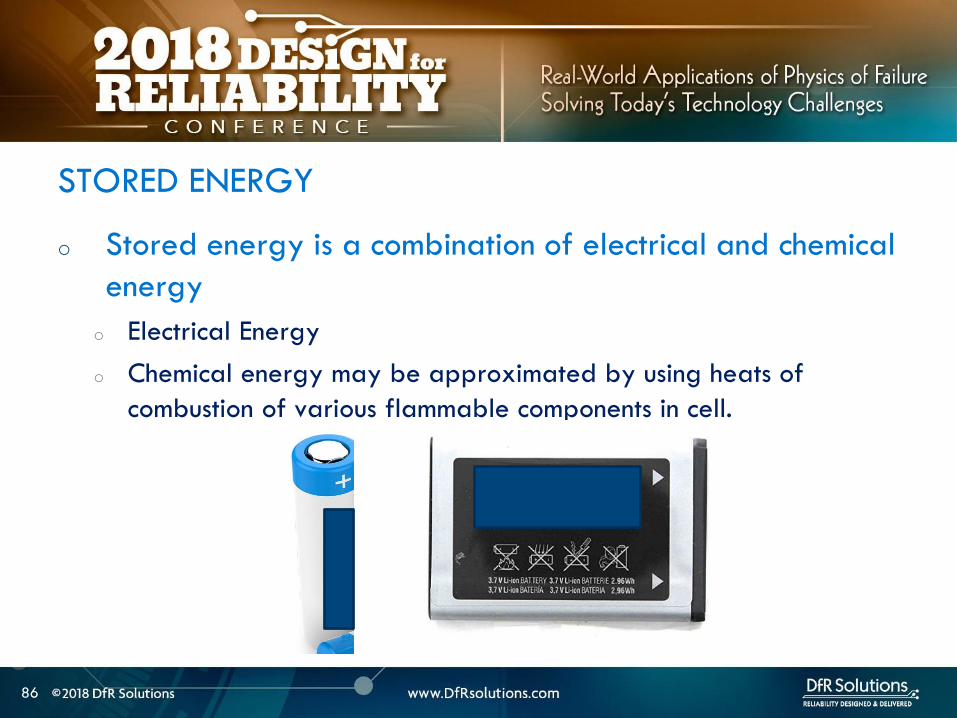
o Stored energy is a combination of electrical and chemical
energy
o Electrical Energy
o Chemical energy may be approximated by using heats of
combustion of various flammable components in cell
STORED ENERGY
87
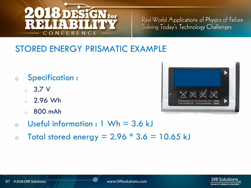
o Specification
o 37 V
o 296 Wh
o 800 mAh
o Useful information 1 Wh = 36 kJ
o Total stored energy = 296 36 = 1065 kJ
STORED ENERGY PRISMATIC EXAMPLE
88
o Assume 1 to 5 g of electrolyte for small prismatic or pouch cell Assume 05 to 1 g of separator
o Electrolyte solvents are generally organic carbonates such as diethyl carbonate (DEC) ethylene carbonate dimethyl carbonate and ethylmethyl carbonate
o Using the heat of combustion of DEC at 2092 kJg 21 to 105 kJ of energy from electrolyte combustion
o Separator is made of polyethylene polypropylene or combination of the two
o By using polypropylene heat of combustion as an approximation at 4266 kJg 21 to 42 kJ energy for the separator
o Total chemical energy approximation is 42 to 147 kJ
STORED CHEMICAL ENERGY SMALL PRISMATIC
89
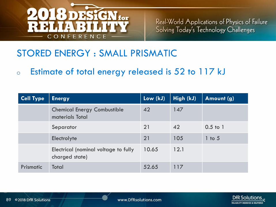
o Estimate of total energy released is 52 to 117 kJ
STORED ENERGY SMALL PRISMATIC
Cell Type Energy Low (kJ) High (kJ) Amount (g)
Chemical Energy Combustible
materials Total
42 147
Separator 21 42 05 to 1
Electrolyte 21 105 1 to 5
Electrical (nominal voltage to fully
charged state)
1065 121
Prismatic Total 5265 117
90
o Specification o 37 V
o 962 Wh
o 2600 mAh
o Useful information 1 Wh = 36 kJo Heat of combustion of DEC = 2092 kJg
o Polypropylene heat of combustion = 4266 kJg
o For comparison a 190 g stick of dynamite can release 1 MJ of energy1
STORED ENERGY 18650 EXAMPLE SOLUTION
Cell Type Energy Low (kJ) High (kJ) Amount (g)
Chemical Energy Combustible materials Total 122 23561
Separator 5972 6825 14 to 16
Electrolyte 6236 16736 3 to 8
Electrical (nominal voltage to fully charged
state)
3462 393
18650 Total 157 207
1 httpsenwikipediaorgwikiDynamite
91
Is the 18650 Hazard
Relevant to You
91
92
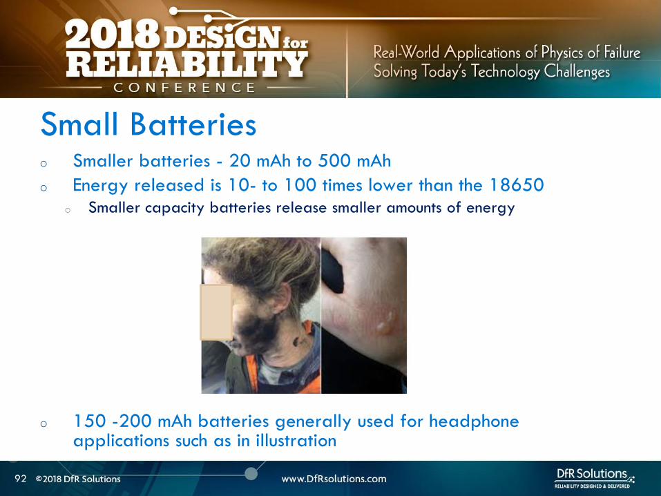
o Smaller batteries - 20 mAh to 500 mAh
o Energy released is 10- to 100 times lower than the 18650o Smaller capacity batteries release smaller amounts of energy
o 150 -200 mAh batteries generally used for headphone applications such as in illustration
Small Batteries
93
o Calculate total energy released from your cell
o Electrical energy + chemical energy
o Use thermal analysis to estimate temperature rise and
compare against allowable surface temperaturesstandards
Worst Case Analysis
Material Burn Threshold for
contact of 05 s (ordmC)
Bare metal 67-73
Ceramics glass and stone 84-90
Plastics 91-99
Wood 128-155
European standard BS EN 132022000
94
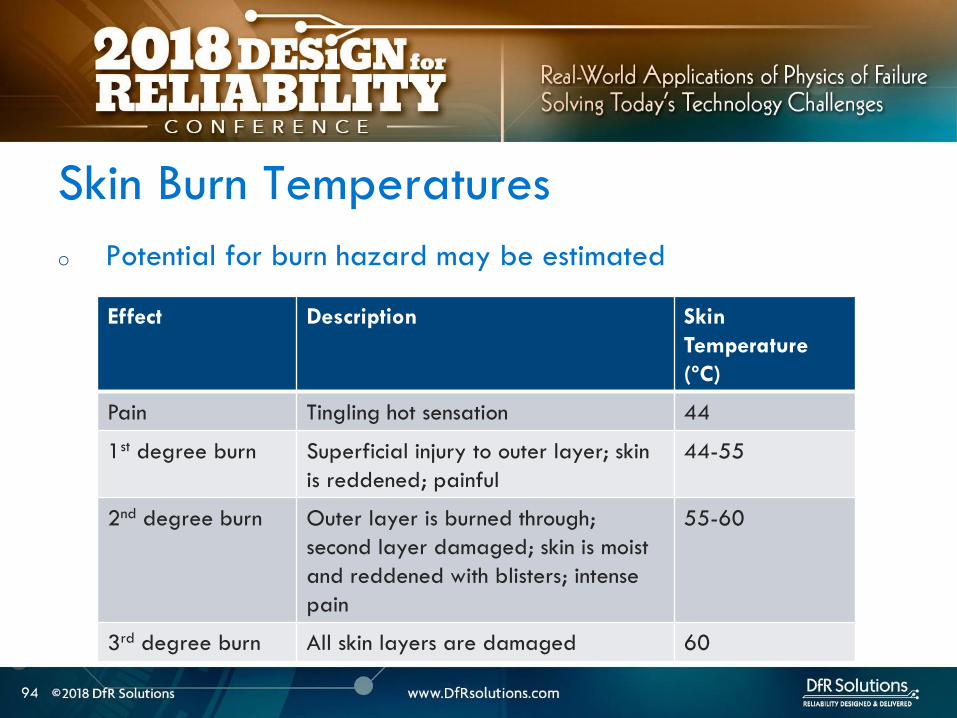
o Potential for burn hazard may be estimated
Skin Burn Temperatures
Effect Description Skin
Temperature
(ordmC)
Pain Tingling hot sensation 44
1st degree burn Superficial injury to outer layer skin
is reddened painful
44-55
2nd degree burn Outer layer is burned through
second layer damaged skin is moist
and reddened with blisters intense
pain
55-60
3rd degree burn All skin layers are damaged 60
95
VENT GAS RISK
95
96
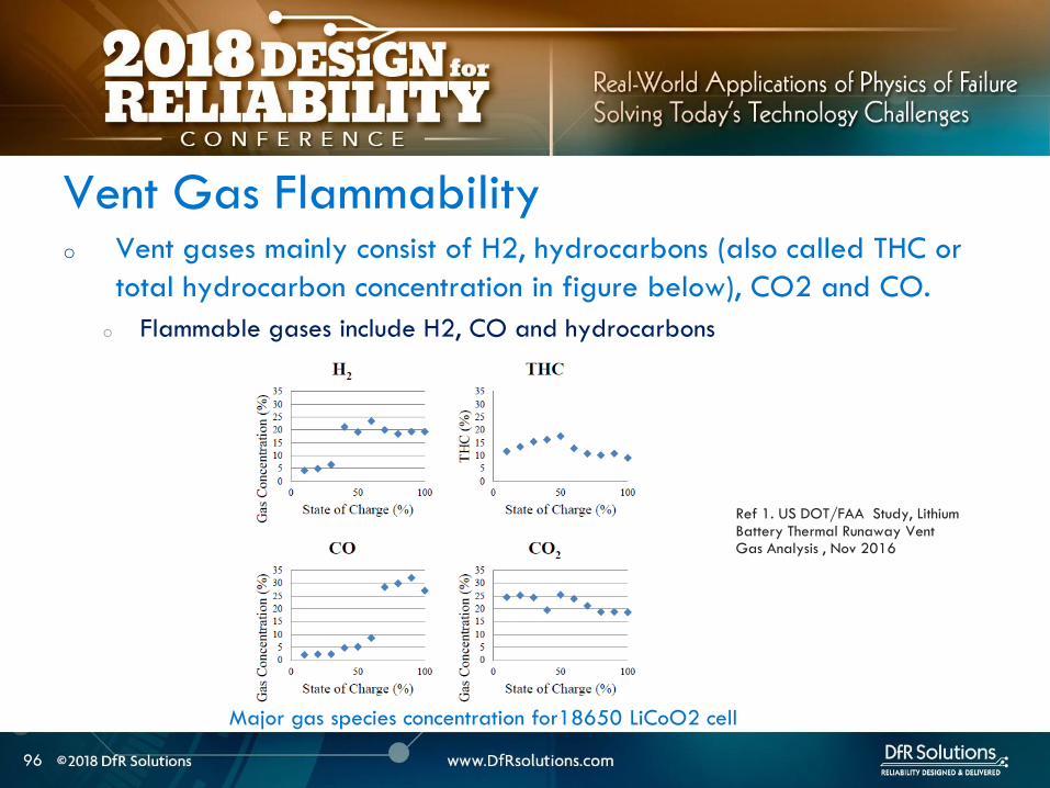
o Vent gases mainly consist of H2 hydrocarbons (also called THC or
total hydrocarbon concentration in figure below) CO2 and CO
o Flammable gases include H2 CO and hydrocarbons
Vent Gas Flammability
Ref 1 US DOTFAA Study Lithium Battery Thermal Runaway Vent Gas Analysis Nov 2016
Major gas species concentration for18650 LiCoO2 cell
97
o When a lithium ion battery vents the gas mixture will mix with surrounding air and may or may not ignite
o The following conditions have to be met for an ignition evento Air fuel mixture is within the Lower Flammability Limit (LFL) and (Upper
Flammability Limit) UFL limits
o Ignition source is present
o The most dangerous materials are those with the lowest flash point and widest flammable ranges
o A hot cell case or hot metal sparks ejected from the cell could create an ignition event if the mixture is within flammability limits
Ignition Risk
98
CHEMICAL SPILL RISK
98
99
o In the absence of a fire potential hazard from a damaged lithium ion battery includes the following
o Release of a electrolyte containing a corrosive salt Electrolyte is extremely corrosive and may cause permanent blindness If ingested through the mouth liver and kidney damage is possible
o Reaction of the electrolyte with waterhumidity may generate hydrofluoric acid which are highly toxic and corrosive to the eyes nose throat and skin
o Release of volatile organics toxic gases such as CO HF
Chemical Spill Risk
Ref Various MSDS sheets
100
o Lithiated carbon in a charged anode the Solid Electrolyte
Interphase (SEI) layer or any free lithium (dendritesplating)
will burst into flames when exposed to moist air
o Reaction of lithium with water produces H2 in an exothermic
reaction
o Significant heat is released in this reaction and this can ignite the H2
Chemical Risk ndash Lithium Ion and Primary Lithium
101
Lithium Ion Life Cycle ndash
Cradle to Grave
101
102
o Cell Manufacturing
o brought to a low to moderate state of charge for shippingstorage
o Transportation
o Warehouse storage
o Pack or device assembly
o OEM device shipment
o Device Usage
o Recycling
LITHIUM ION BATTERY LIFE CYCLE
103
o Almost all failures are related to improper packaging (potential for mechanical damage and external shorts) and shipment procedures
o International Air Transportation Association (IATA) shipment procedures for dangerous goods Cell manufacturers must show proof of UN 383 certification
o 1) Lithium ion batteries (not contained in equipment) shall not be shipped with SOC greater than 30
o 2) Shall pass UN 383 battery of tests
o 3) Shall not be shipped on passenger aircraft
Transportation Procedures
See httpwwwiataorgwhatwedocargodgrDocumentslithium-battery-shipping-guidelinespdf
104
o Small cell shipment exceptions to class 9 dangerous goods classification
o Only Carry-on and Section II are exempt from Class 9 hazardous material
designation
Transportation Procedures
Image source
Battery university
105
o Have procedures in place for safe handling of lithium ion
batteries
o Protection from short circuit high temperature is critical
o Pouch cells must use recessed packaging trays
Storage and Warehouse Handling
106
o Do not single stream recycle lithium ion batteries
o High risk of ignition with surrounding paper and cardboard
o Lithium Ion batteries can be recycled but only at specified
locations Visit httpswwwcall2recycleorglocator
(Rechargeable Battery Recycling Corporation)
o 86 of US and Canadian residents live within 10 miles of
drop-off location
o httpswwwcall2recycleorg for battery recycling resources
Lithium Ion Recycling Procedures
107
o Do not discard as trash
o When collecting batteries make sure they are taped or
insulated
o Recommend drop-off instead
Lithium Ion Recycling Procedures
108
COMPLIANCE TESTING
108
109
o Tests that have the same name under different standards are not always the same
o There are differences in terms of the state of charge aging of the cells and sample sizes and these can have significant differences
o The vendor must state the test standard specify a test description in addition to the name of the test
BATTERY COMPLIANCE TESTING
110
o UNDOT 383 Covers transportation safety testing for all lithium
metal and lithium ion cells and batteries This is mandatory
o UL safety standards
o UL 1642 ndash This standard is used for testing lithium cells Battery level tests
are covered by UL 2054
o UL 2054 (Household and Commercial Batteries) ndash For lithium batteries UL
2054 defers all component cell level testing to UL 1642
o CEIIEC 62133 ndash this standard is voluntary in the US but some
countries specify this standard
BATTERY COMPLIANCE TESTING
111
o IEEE 16251725 ndash These standards are applicable to rechargeable batteries for Multi-cell mobile computing devices and for Cellular phones respectively (CTIA or Wireless Association)
o These standards take the most comprehensive approach to battery testing and emphasize that battery pack safety is a function of a) the individual cells b) the battery pack c) the host device d) power supply accessories e) the user f) the environment
o Both standards require design analysis tools such as FMEA or fault tree analysis They also encompass industry best practices in manufacturing and in the areas of cell pack system and charging accessory design
BATTERY COMPLIANCE TESTING
112
The more you know the better
Parting Thought
Questions
bull Contact Vidyu Challa
vchalladfrsolutionscom
301-640-5834
bull wwwdfrsolutionscom resources page for
battery and other electronic reliability
resources
114
APPENDIX
114
115
Battery Seal Quality
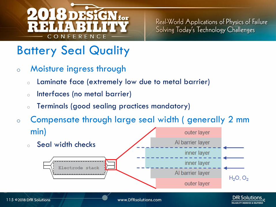
o Moisture ingress through
o Laminate face (extremely low due to metal barrier)
o Interfaces (no metal barrier)
o Terminals (good sealing practices mandatory)
o Compensate through large seal width ( generally 2 mm
min)
o Seal width checks
116
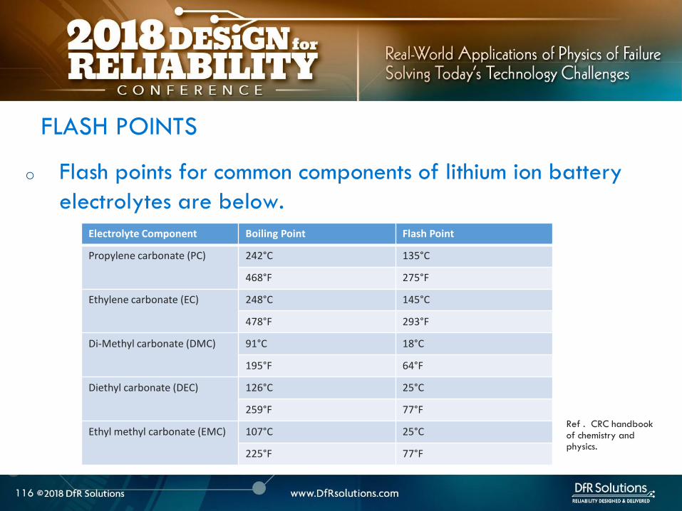
o Flash points for common components of lithium ion battery
electrolytes are below
FLASH POINTS
Ref CRC handbook of chemistry and physics
Electrolyte Component Boiling Point Flash Point
Propylene carbonate (PC) 242degC 135degC
468degF 275degF
Ethylene carbonate (EC) 248degC 145degC
478degF 293degF
Di-Methyl carbonate (DMC) 91degC 18degC
195degF 64degF
Diethyl carbonate (DEC) 126degC 25degC
259degF 77degF
Ethyl methyl carbonate (EMC) 107degC 25degC
225degF 77degF
117
o Flammability limits for vent gases from Li Ion batteries are in
table below
Ref Combustion Flames and Explosion of Gases 2nd Edition Academic Press NY 1961
Compound Lower flammability limit
(fuel volume )
Upper flammability limit
(fuel volume )
Hydrogen 40 750
Carbon monoxide 125 740
Methane 53 150
Ethylene 31 320
Ethane 30 125
Propylene 24 103
C4 hydrocarbons ~ 16-19 ~ 84 ndash 97
C5 hydrocarbons ~ 14-15 ~ 75 ndash 87
o Samsung 2016 Root Cause Analysis
o Battery failure mechanisms and modes ndash pathway to thermal runaway
o Battery protection mechanismso Internal and External
o Mitigation methodso Design
o Manufacturing
o Battery Management System
o Application Assembly and Storage
o User
o Summary
OUTLINE
3
o Anode negative electrode cathode positive electrode
o Lithium ion is an intercalation battery (lsquorocking chair
mechanismrsquo)
o insert between layers or in crystal structure
Li Ion Battery Working Mechanism
4
o Solid electrolyte interphase (SEI) formed during first few
charging cycles
o SEI can be unstable outside operating window
Solid Electrolyte Interphase
5
Graphite Anode SEI Organic Electrolyte
6
Samsung 2016 Battery Failures
6
Source Samsung Galaxy Note 7 failure investigation press conference Jan 2017 All Information in public domain
o Galaxy Note 7 fires were reported within a few weeks of the product launch
o Samsung recalled affected phones and pointed to a manufacturing error from its battery supplier Samsung SDI
o The batteries were swapped with ones from its Chinese supplier ATL
o Replacement phones that were supposed to be ldquofixedrdquo also started to catch on fire
o Samsung scrapped the entire product line 25 million phone recalls prior Cost Samsung $5 Billion
Samsung Galaxy 2016 Failures
7
Flattened Jellyroll Pouch Cell Design
8
o Damage to the negative electrode windings caused by
deflection by a pouch design that did not provide sufficient
volume to accommodate the electrode assembly
o Curvature of pouch causes deflection of the negative electrodes
Manufacturer A Root Cause
9
o Negative electrode damage provides multiple pathways to cell internal short circuit and thermal runaway under normal cycling conditions
o Damage to the separator
o Lithium plating
Negative Electrode Deflection
10
Source Information in public domain
Overcrowded Bus Analogy
11
o Tab welding defect created an internal short
Manufacturer B Root Cause
12
o Poorly controlled
welding process - Burr
height 80 microm in some
cases
o Normal swelling and
contraction occurs
during charge-
discharge cycling
o Some batteries were missing the insulation tape
o Samsung blames the flaws on its factories trying to get production started too quickly to counteract lost sales
o There are simply no short cuts when it comes to lithium ion battery manufacturing process control
Manufacturer B Root Cause
13
14
LITHIUM ION BATTERY
FAILURE MODES AND
MECHANISMS
14
LITHIUM ION BATTERY FAILURE MODES
15
Lithium Ion Battery Failures
Non-energetic
Failures Energetic Failures
Explosion
IR
Increase
Permanent
Safety Feature
Enabled
Cell
swelling
Electrolyte
leakage
Capacity
Loss
Fire Venting
o All non-energetic failures are not benign
o What dictates whether a failure is energetic or not
o Same initiating fault can have different outcomes
o Depends on whether the initiating fault can create a self-
sustaining exothermic reaction
BENIGN ENERGETIC AND NON-ENERGETIC
16
LITHIUM ION BATTERY FAILURE CAUSE
17
Elevated Cell
Temperature
Heat
Dissipatedgt
Heat
Generated
Heat
Dissipatedlt
Heat
Generated
Non-
energetic
Failures
Thermal
runaway
Overcharge
Overdischarge
High ambient temp
External short circuit
Internal short
circuit
Metallic ContaminationBurrsweld
defects
Lithium PlatingMechanical
damage
Low
Anodecathode
ratio
Anode delam
Low electrolyte
OutcomeCauseMitigation
Safety
electronics
and cell
internal
safety
features
Manufacturing
quality and
process control
Low temp
charging
Design
o Breakdown of passivating SEI layer on anode
o Excessive currents overcharging or high external ambient temp
o Starts at 80 C New SEI formed but at a higher uncontrolled rate in an
exothermic reaction Self accelerating reaction
o Electrolyte breakdown
o Organics in the electrolyte break down releasing flammable hydrocarbon
gases but no oxygen
o Typically around 110 -120 C
o Pressure starts to build up Even
if temp rises above flash point
no burning due to lack of oxygen
CELL REACTIONS AT ELEVATED TEMP -1
18
o Safety vent pops to prevent explosion (18650 metal can type) ndashnow have oxygen available
o Separator melting occurs around 155 C causing electrodes to short
o Further temperature rise causes metal oxide breakdown at cathode releasing oxygen in an exothermic reaction For Cobalt oxide this happens at 200 C
o Highly flammable organics elevated temp and oxygen
CELL REACTIONS AT ELEVATED TEMP -2
19
o Elevated temperature and cell failure are intricately tied together
o Elevated temperature negatively impacts capacity
o At higher rates higher capacity degradation
o 50 Loss in cycle life from 1 C to 12 C charging rate
o Cannot be explained by temperature rise alone
ELEVATED TEMP AND FAILURES
20
Choi S S amp Lim H S (2002) Factors that affect cycle-life and
possible degradation mechanisms of a Li-ion cell based on LiCoO2
Journal of Power Sources 111(1) 130-136
o Rapid performance degradation (sudden death) ndash lithium plating is highly reactive to electrolyte
o electrolyte and lithium consumption causing electrode dry out
o further lowering of anode to cathode ratio
o increased impedance and further risk of plating
o Safety issues ndash risk of dendritic growth exothermic reaction between plated lithium and electrolyte
LITHIUM PLATING ndash WHY IS IT BAD
21
Image source Safety of Lithium-Ion Batteries
Zhang et al Lithium-Ion Batteries
Advances and Applications
2014 Pages 409ndash435
o When does it happeno Operation outside specification window- overcharging high charging rate low temperature
(protection circuitry)
o Batteryapplication design ndash low anodecathode low electrolyte mechanical deformation from product (design engineeringquality)
o Manufacturing defects ndash eg anode delamination mechanical deformation poor quality cells (quality engineering)
LITHIUM PLATING
22
Image Source Understanding
undesirable anode lithium
plating issues in lithium-ion
batteries Liu et al RSC Adv
20166
LITHIUM ION SAFETY
23
Abuse Manufacturing Defects
Cell amp Application Design
Handling
Thermal Abuse
Electrical Abuse
Mechanical Abuse
2 90 5 3
bull BMS amp Circuitrybull Standardized Tests
Fiel
d F
ailu
re
Mit
igat
ion
Val
Fa
ilure
Cau
ses
Nea
r M
iss
Even
ts
0 50 25 25
Internal Shorts Cell Design
Application design
Storage
Assembly into host device
bull Quality Process Control
bull CT scansManuf audit
bull Design reviewsbull CT ScansApp
specific testing
bull Process and procedure review
bull Self discharge tests
User
24
Internal Shorts ndash lsquoSoft underbellyrsquo
Internal shorts are typically the result of manufacturing defects
and are not effectively mitigated by safety systems
There is no good internal short circuit test that effectively
screens out these defects
The best defense is to have sound manufacturing process
controls
24
25
Improper BMS Design
o Poorly designed BMS and use of improper chargers are
responsible for some of the spectacular field failures
o Over-voltage failures are more spectacular and immediate than
grown in manufacturing defects which can take time to manifest
themselves
o Battery protection system includes the charger circuitry
protection circuit module located at the battery and is
optimized for a specific cell chemistry and application
o Good BMS design should include use of a custom connector so that
everyday USB chargers canrsquot be plugged in and allowed to abuse the
cell
26
LITHIUM ION CELL
MANUFACTURING PROCESS
26
27
o Incoming raw materials
o Electrode fabrication and cell assembly
o Environmental control
MANUFACTURING CONTROLS
28
o Energy density
o Pack as much active material as possible
o Minimize fines which make wetting difficult and require more
solvent and lower the solids content in slurry
o Power density
o Higher void volumes lower
electrode pressed density
and thickness
POWER DENSITY VS ENERGY DENSITY
29
o Incoming powders ndash Tap density particle size distribution
(PSD) surface area purity
o Binders and binder solvents
o Separator
o Electrolyte
o Current collectors
o Dry room storage (dew point of at least -40 C) Dew point is
used to express water vapor concentration at this level because
the corresponding relative humidity value is less than 1
MANUFACTURING INCOMING RAW MATERIALS
Separator
ELECTRODE FABRICATION
30
QC -Viscosity and
dispersion control
Riskndash shorts unreacted
lumps cause risk of
dryout and plating
QC ndashthickness slurry
metering
Riskndash non-uniform
coating leading to
shorting risk dryout
QC ndash thickness
adhesion
Riskndash blisters lack of
adhesion leading to
lithium plating
QC ndash electrode
thickness oncehr roller
gap check 4-6 hrs
porosity Riskndashlack of
cell performance for
energy or power
QC ndashburr control
tension control cutting
wheel maintenance
Riskndashinternal shorts
CELL ASSEMBLY FORMATION AND TESTING
Battery Manufacturing (nd) Retrieved March 22 2017 from httpw3siemenscommarketsglobalenbattery-
manufacturingapplicationsprocesspagesdefaultaspx
WindingStacking
QC ndashalignment
Riskndashinternal shorts
Tab welding
QC ndash burrweld height
control
Risk ndash internal shorts
QC ndash Weight before and
after stringent moisture
control
Risk ndash electrode dryout and
plating swelling from
moisture
QC ndash OCV IR weight
dimension check prior to
formation Rest to allow
electrolyte wetting after
filling followed by
formation
QC ndash OCV IR weight
dimension followed by
aging qualification tests
32
o The process involves a multi-zone oven with low temperatures for the first zone higher temperatures for the middle zone followed by a lower temperature for the final zone
o Specific temperatures will depend on binder chemistry and on slurry properties
o For PVDF binder on the cathode the recommended drying oven temperature profile for a 5-zone oven is as follows zone 1 ndash 75-90 degC zones 2-4 ndash 125-130 deg C zone 5 ndashapproximately 75 deg C A 4-zone oven should run at slower speed to allow more solvent evaporation
DRYING TEMPERATURES
33
o Incoming materials control
o Internal specifications that identify minimize and control all known
and likely impurities in incoming materials
o Internal specifications that control material properties or specs
o Ability to track changes in vendor materials
GENERAL MANUFACTURING GUIDELINES
34
o Manufacturing process control
o Safety critical equipment must be identified - process of verifying
equipment operation periodically Preventive maintenance plan
implementation
o Procedures to avoid metal contamination throughout the manufacturing
process
o Processes to collect loose material such as coating dust
o A method of detecting mechanical damage to electrodes in the
manufacturing process such as an automated vision system
o Statistical process control (SPC) to monitor maximum particle size slurry
viscosities coating weight calendered thickness weight of electrolyte
dispensed cell weight open circuit voltage (OCV) and capacity
GENERAL MANUFACTURING GUIDELINES
35
o Robust environmental control with a specific focus keeping ambient moisture minimized
o Destabilizes SEI layer and electrolyte and causes gassing
ENVIRONMENTAL CONTROL
36
LITHIUM ION CELL DESIGN
GUIDELINES
36
37
o Anode should overhang cathode by 05 mm or more on all sides for stacked cell or along top and bottom ends for jellyroll (min of 01 mm per IEEE 16251725)
o Anode should have higher electrochemical capacity than cathode by 10-15
o Example 1 g anode specific capacity is 350 mAhg So total anode capacity is 350 mAh
o 1 g cathode with specific capacity of 280 mAhg has total capacity of 280 mAh
Cathode shall never put out more lithium
ions than the anode can accommodate
CELL DESIGN GUIDELINES
Cathode
Separator
Anode
38
o Separator overhangs anode on all sides (room temperature to
at least 110 C- IEEE 16251725)
o Less than 5 shrinkage in both machine and transverse
directions at 90 C as a minimum
o Separator should have sufficient mechanical
strength to withstand cell assembly operations
CELL DESIGN GUIDELINES
Cathode
Separator
Anode
39
o Product design ndash make sure there is enough room for battery to
expand as it goes through charge ndashdischarge cycles Recommend 10
margin
o Pay particular attention to corners
o Poor manufacturing can reduce design margin
o Cutting operation variability
o Pick and place variability
CELL DESIGN GUIDELINES
40
ARTICLE QUALITY ASESSMENT
CELL CT SCANS AND
TEARDOWN
40
41
o Deep discharged cell
ARTICLE QUALITY ASESSMENT ndash CT SCANS
42
o Exercise - Describe what you see
o Electrode alignment is good on right image
o Variability in jellyroll winding on left and middle images
o Insufficient anode overlap in center of middle image
ARTICLE QUALITY ASESSMENT- CT SCANS
43
o Conduct CT scans and cell teardowns on a handful of units
o What to look for in CT scans
o Uniform cell winding or stacking
o No particulates
o No significant electrode delamination
o Anodes should overhang cathode by 05 mm ideally but a minimum
of 01 mm on each side
o No excessive deformation at pouch corners
o Cutting operationpick and place variability
PHYSICAL ARTICLE QUALITY ASESSMENT ndash CT SCANS
44
o Look at a few electrode pieces using optical microscopy
and SEMEDS
ARTICLE QUALITY ASESSMENT ndash TEARDOWNS
45
LITHIUM ION INTERNAL
AND EXTERNAL
PROTECTION SYSTEMS
45
o Positive Temperature Coefficient (PTC) device - inhibit high current surges
o Charge interrupt device (CID)- opens the electrical path if an excessively high charge voltage raises the internal cell pressure to a threshold value
o Safety vent- allows a controlled release of gas in the event of a rapid increase in cell pressure
o Hot electrolyte vapors and gas will always blow towards the burst disc instead of splitting the sides
o Shutdown Separators
CELL SAFETY PROTECTION MECHANISMS
46
o PTC - doughnut shaped device that sits between two metal
plates and is made of a polymeric material
o At high currents or temperatures resistance of the PTC increases
sharply causing the current to drop
PTC DEVICE
47
Image source nasagov
o The PTC is resettable and reverts
back after the fault is removed
o Once activated it subsequently
activates at a lower current and
temperature
o Works by releasing the connection at the positive terminal and
opening the electrical path
o Pressure valve which will disable the cell permanently of
pressure in the cell is too high
o Is not resettable
CHARGE INTERRUPT DEVICE
48
Image source nasagov
o Pouch cells do not have an internal CID PTC or safety vent
o Can have PTC or fuse elements in series with cell
POUCH CELL PROTECTION
49
Image source nasagov
50
o Separator is usually made of polyethylene (PE) polypropylene (PP) or a combination of the two
o Inner PE layer shuts down at 130degC by closing the pores the outer PP layers do not melt until reaching 155degC
SHUTDOWN SEPARATOR
Image Source Battery University
51
o Separator should increase its resistance by two orders of
magnitude at shutdown temperature (typically 130 C)
SHUTDOWN CURVES
Image Source Arora and Zhang Battery Separators Chem Rev 2004 104 (10) pp 4419ndash4462
52
o Know separator propertieso Thickness
o single vs multiple layer (PE PP or combination)
o ceramic coated or not
o Ceramic coatings can enhance thermal stability and prevent separator collapse till 200 C and beyond
o Ceramic coated separators usually may not have the mechanical strength to withstand winding and assembly- irrelevant for prismatic or stacked designs
SHUTDOWN SEPARATOR PROPERTIES
Impedance (1 kHz AC) vs Shutdown temperature of electrolyte soaked separators (ab) Polyethylene and (c)
polypropylene
53
BATTERY MANAGEMENT
SYSTEM (BMS) AND
PROTECTION CIRCUITRY
53
54
o Operating outside of specifications
Operating Outside Specifications
Image source Electropaedia
55
o Depends on a number of factors
o State of charge (SOC)
o Ambient temperature
o Cell chemistry
o Cell design
o Most severe thermal runaway occurs in an overcharged state
o Case temperatures can reach 600 C
o High temperatures are driven by exothermic reactions of the electrodes and the electrolyte
Severity of Thermal Runaway
56
o Self heating temperature o Fully charged 18650 cells brought to self heating temperature
(70 to 90 C) in adiabatic environment go into thermal runaway in 2 days
o Fully charged 18650 in adiabatic environment brought to 150 C (with separator melting) will run away in minutes
o UL standard requires fully charged cells to withstand 4 hour storage at 75 C and 10 min storage at 130 C
o IEEE standard requires 1 hour exposure at 130 C
o Overcharge o Charging a 42 V system to 5 V will almost certainly cause
immediate thermal runaway
Thermal Runaway Initiation ndash Some Numbers
57
o EV electric bus caught fire in Shenzhen China during
charging
o BMS Failure
o Without a BMS there is no
safe lithium ion battery
EV Bus Failure
58
o Consist of charger and a battery protection printed circuit board (PCB)
o Also called a battery protection circuit module (PCM)
o Important functions of protection systems include monitoring controlling and terminating charge and discharge as needed
o Failure of protection circuitry to either sense or respond to an out of range condition causes battery failure
ELECTRONIC PROTECTION SYSTEMS
59
o Maintain cells within operating window and prevent cells
from going into
o Over voltage
o Over current
o Over temperature
o Over discharge
o Balance individual cells to enhance overall capacity
o Disconnect batteries in a safe way in emergency situations
o Predict remaining capacity or state of charge
BMS FUNCTIONS
BMS Webinar httpswwwdfrsolutionscombattery-management-systems-and-safety-and-reliability-webinar
60
o Most obvious failure mode is exceeding specified voltage
o Charging a 42 V system to 5 V will almost certainly cause immediate thermal runaway
o Charging at excess currents
o Overcharge effects
o Anode ndash lithium plating rather than intercalation
o Cathode ndashexcess de-intercalation causes crystal structure to collapse and release heat
o Heat and gas release (both Joule heating and parasitic reactions)
o Electrolyte and electrode decomposition
OVER CHARGE - VOLTAGE
61
o Over voltage may be applied to the battery from a defective charger or due to improper monitoring on a single cell
o Slight overcharge (from minor deviations in voltage monitoring) causes capacity loss rather than direct thermal runaway
o Overvoltage protection can be implemented by opening a charge MOSFET or a fuse
o Overcharge protection is so critical that multiple independent circuits are typically used to prevent single points of failure
OVER VOLTAGE
62
o Hazard from over discharge is highly underestimated
o When a cell goes into deep discharge copper ions from the negative electrode current collector dissolve On recharge copper dendrites can form
o Over discharge can also cause breakdown of the SEI layer and gas formation
OVER DISCHARGE
Image Source Rui Guo1 Languang
Lu1 Minggao Ouyanga1 and Xuning
Feng1 Sci Rep 2016
63
How Does a Battery Go into
Deep Discharge
63
64
o Uncontrolled storage without appropriate recharge
procedures
o Mechanically damaged cells (from electronics impinging
on cell)
OVER DISCHARGE SCENARIOS
65
o Three kinds of discharge occur during storage o PCM sleep current and leakage currents
o Battery self discharge
o Manufacturing quality
o Temp
o State of charge
o Device sleep currents
o At 3 V (or other threshold cutoff) load is disconnected although above lsquoconsumption currentsrsquo are active
o At deep discharge cutoff value of 2 V (or other manufacturer specified value) PCM and device sleep currents are turned off but battery self discharge continues
Discharge During Storage
66
o Lithium ion self discharge around 1-2 per month + a
few cent for PCM
o High SOC and temperatures degrade storage life (and
cycle life)
o Rule of thumb ndash 10 C increase in temperature doubles self
discharge rate
o Store at conditions close to 25 C and 40 SOC
Battery Self Discharge
67
o To keep the contamination as low as possible to reduce
leakage current de-ionized water wash should be used
in the board cleaning process
o Verify the board cleanliness to make sure the levels of
contamination is low
o Investigate if humidity is an issue and that conformal
needs to be used
PCM (BMS) Self Discharge
68
o Have a pre-check charging function on batteries where deep discharge cutoff voltage was reached Charger circuit checks if a deeply discharged battery is reaches a threshold value in give time Otherwise considered a lsquodamagedrsquo battery
o Mitigating hazard from copper shunts
o Proper battery storage and recharge procedures
o Minimize PCM leakage currents
o Ensure cell quality
o Prevent cell mechanical damage
Deep Discharge Checklist
69
o Over current can causeo Degradation in cycle life
o Thermal runaway
o Threshold limits for current are functions of both current and time Protection circuit system can use different combinations of time and current to produce a fault Example - high currentshort time or lower currentlong time
o Some faults are recoverable such as when a MOSFET is turned on and others are non-recoverable such as when a fuse is ignited
o Causes of over-current could be a defective charger or due to an internal short
OVER CURRENT PROTECTIONS
70
o A good battery management system will limit charge current and voltage at high and low temperature extremes per Japan Electronics and Information Technology Industries Association (JEITA) guidelines
OVER CURRENT
(60 degC)
CoolCold Warm Hot
(0 degC)
Reduce charging
current andor
voltage
Reduce charging
current andor
voltage
71
o Current limits are incorporated into the protection
circuits located in pack or device
o Circuits monitor current in and out of battery and open up
MOSFET to interrupt current
o Backup protection usually includes a fuse or PTC placed
in series with battery pack
SHORT CIRCUIT PROTECTION
72
BATTERY LIFE DEGRADATION
AND STORAGE
72
73
o Battery life example
o Nominal capacity is 2900 mAh End of life capacity at 80 of initial capacity is 2300 mAh
o Is this data sufficient to give you a life of 500 cycles
BATTERY LIFE AND AGING ISSUES
74
o Calendar aging vs cycle life agingo Insertion or ejection of the Lithium ions into and out of the intercalation
spaces during cycling causes the electrode materials to swell or contract
o Repetitive cycling can weaken the electrode structure reducing its adhesion to the current collector This can lead to reduction in charge capacity
BATTERY LIFE DEGRADATION
75
o Storage degradation high temperature aging causes
growth of the passivating layer
o It consumes lithium and electrolyte and leads to capacity loss
and impedance increase (both capacity and power fade)
Pores can be blocked as a result
o Low rate batteries may not see a big impact
(voltage drop = IR)
BATTERY LIFE DEGRADATION CALENDAR AGING
76
o Have two distinct mechanisms
that impact cell life
o Battery aging tests should
involve high temperature
storage tests
BATTERY LIFE DEGRADATION CALENDAR AGING
Image source Electropaedia
77
o Characterize both reversible and irreversible storage loss
o In this example 25 irreversible and 5 reversible
capacity loss
REVERSIBLE VS IRREVERSIBLE STORAGE LOSS
Assume a = 2900 mAh
d = 70 a = 2030 mAh
e = 95 a = 2700 mAh
a
d
e
78
LITHIUM ION CHEMISTRIES
78
79
o Term Lithium-Ion encompasses many different chemistries
o Anode ndash graphite (Lithium Titanate LTO for very fast charge cells)
o Cathode - Cathodes are lithiated metal oxides or lithiated metal
phosphates
o Lithium Cobalt Oxide (LCO)
o Lithium Iron Phosphate(LFP)
o Nickel Manganese Cobalt (NMC)
o Lithium Manganese Oxide(LMO)
o Cathode chemistry is where you get enhancements in safety
energy and power density
Battery Chemistry
80
o Lithium Cobalt Oxide (LCO) ndash commonly used in consumer electronics
o High energy density
o Low power
o Least safe
o Moderate cycle life
Battery Chemistry
o Lithium Iron Phosphate(LFP) ndashndash automotive power tools UPS e-cigs
o Safest chemistry
o High power density
o Very high cycle life
o Lower voltageLower energy density
o Higher self discharge rate
81
o Nickel Manganese Cobalt (NMC) ndashcommon in tools EV applications
e-cigs ndash usually 13 proportion but customization is possible
o Can be optimized for power or energy
o Good safety
o Good cycle life
Battery Chemistry
o Lithium Manganese Oxide(LiMn2O4) ndashndash power tools EV and hybrid vehicles e-cigs
o Low internal resistancehigh power capability (from Manganese)
o Good safety
o Lower energy ndash blends with NMC are used to enhance energy
82
Battery Chemistry Summary
Chemistry LCO NMC LFP LMO
Nominal Voltage(V) 36-37 36-37 32-32 36-37
Charge Voltage(V) 42 42 35-36 42
Safety Poor Good Highest Good
Cycle Life gt500 gt500 gt1000 gt500
Peak Load current (Best result) 2C
(lt1C)
gt30C
(lt10 C)
gt30C
(lt10 C)
Specific energy (WhKg) 150-250 90-120 100-150
Thermal Runaway Temp (ordmC) 150 210 gt270
Used Since 1991 2003 1999 1996
Designation ICR INR IFR IMR
o Knowing chemistry helps to map out worst case scenario
o For pouch cells look at MSDS
83
o Do not see the word LCO
Battery Chemistry in Current EV Systems
84
ESTIMATING STORED ENERGY
84
85
o Risk assessment
o How much energy and wattage does the battery have
o How fast is the energy released
o Is the product worn on or close to the body
o What is the chemistry
o New product category Are there specific user behaviorsproduct
design interactions that increase the risk and impact of thermal away
o Risk mitigation
o Trust but verify
o Do not trust till you verify
o Map out the worst case
BATTERY RISK ASESSMENT
86
o Stored energy is a combination of electrical and chemical
energy
o Electrical Energy
o Chemical energy may be approximated by using heats of
combustion of various flammable components in cell
STORED ENERGY
87
o Specification
o 37 V
o 296 Wh
o 800 mAh
o Useful information 1 Wh = 36 kJ
o Total stored energy = 296 36 = 1065 kJ
STORED ENERGY PRISMATIC EXAMPLE
88
o Assume 1 to 5 g of electrolyte for small prismatic or pouch cell Assume 05 to 1 g of separator
o Electrolyte solvents are generally organic carbonates such as diethyl carbonate (DEC) ethylene carbonate dimethyl carbonate and ethylmethyl carbonate
o Using the heat of combustion of DEC at 2092 kJg 21 to 105 kJ of energy from electrolyte combustion
o Separator is made of polyethylene polypropylene or combination of the two
o By using polypropylene heat of combustion as an approximation at 4266 kJg 21 to 42 kJ energy for the separator
o Total chemical energy approximation is 42 to 147 kJ
STORED CHEMICAL ENERGY SMALL PRISMATIC
89
o Estimate of total energy released is 52 to 117 kJ
STORED ENERGY SMALL PRISMATIC
Cell Type Energy Low (kJ) High (kJ) Amount (g)
Chemical Energy Combustible
materials Total
42 147
Separator 21 42 05 to 1
Electrolyte 21 105 1 to 5
Electrical (nominal voltage to fully
charged state)
1065 121
Prismatic Total 5265 117
90
o Specification o 37 V
o 962 Wh
o 2600 mAh
o Useful information 1 Wh = 36 kJo Heat of combustion of DEC = 2092 kJg
o Polypropylene heat of combustion = 4266 kJg
o For comparison a 190 g stick of dynamite can release 1 MJ of energy1
STORED ENERGY 18650 EXAMPLE SOLUTION
Cell Type Energy Low (kJ) High (kJ) Amount (g)
Chemical Energy Combustible materials Total 122 23561
Separator 5972 6825 14 to 16
Electrolyte 6236 16736 3 to 8
Electrical (nominal voltage to fully charged
state)
3462 393
18650 Total 157 207
1 httpsenwikipediaorgwikiDynamite
91
Is the 18650 Hazard
Relevant to You
91
92
o Smaller batteries - 20 mAh to 500 mAh
o Energy released is 10- to 100 times lower than the 18650o Smaller capacity batteries release smaller amounts of energy
o 150 -200 mAh batteries generally used for headphone applications such as in illustration
Small Batteries
93
o Calculate total energy released from your cell
o Electrical energy + chemical energy
o Use thermal analysis to estimate temperature rise and
compare against allowable surface temperaturesstandards
Worst Case Analysis
Material Burn Threshold for
contact of 05 s (ordmC)
Bare metal 67-73
Ceramics glass and stone 84-90
Plastics 91-99
Wood 128-155
European standard BS EN 132022000
94
o Potential for burn hazard may be estimated
Skin Burn Temperatures
Effect Description Skin
Temperature
(ordmC)
Pain Tingling hot sensation 44
1st degree burn Superficial injury to outer layer skin
is reddened painful
44-55
2nd degree burn Outer layer is burned through
second layer damaged skin is moist
and reddened with blisters intense
pain
55-60
3rd degree burn All skin layers are damaged 60
95
VENT GAS RISK
95
96
o Vent gases mainly consist of H2 hydrocarbons (also called THC or
total hydrocarbon concentration in figure below) CO2 and CO
o Flammable gases include H2 CO and hydrocarbons
Vent Gas Flammability
Ref 1 US DOTFAA Study Lithium Battery Thermal Runaway Vent Gas Analysis Nov 2016
Major gas species concentration for18650 LiCoO2 cell
97
o When a lithium ion battery vents the gas mixture will mix with surrounding air and may or may not ignite
o The following conditions have to be met for an ignition evento Air fuel mixture is within the Lower Flammability Limit (LFL) and (Upper
Flammability Limit) UFL limits
o Ignition source is present
o The most dangerous materials are those with the lowest flash point and widest flammable ranges
o A hot cell case or hot metal sparks ejected from the cell could create an ignition event if the mixture is within flammability limits
Ignition Risk
98
CHEMICAL SPILL RISK
98
99
o In the absence of a fire potential hazard from a damaged lithium ion battery includes the following
o Release of a electrolyte containing a corrosive salt Electrolyte is extremely corrosive and may cause permanent blindness If ingested through the mouth liver and kidney damage is possible
o Reaction of the electrolyte with waterhumidity may generate hydrofluoric acid which are highly toxic and corrosive to the eyes nose throat and skin
o Release of volatile organics toxic gases such as CO HF
Chemical Spill Risk
Ref Various MSDS sheets
100
o Lithiated carbon in a charged anode the Solid Electrolyte
Interphase (SEI) layer or any free lithium (dendritesplating)
will burst into flames when exposed to moist air
o Reaction of lithium with water produces H2 in an exothermic
reaction
o Significant heat is released in this reaction and this can ignite the H2
Chemical Risk ndash Lithium Ion and Primary Lithium
101
Lithium Ion Life Cycle ndash
Cradle to Grave
101
102
o Cell Manufacturing
o brought to a low to moderate state of charge for shippingstorage
o Transportation
o Warehouse storage
o Pack or device assembly
o OEM device shipment
o Device Usage
o Recycling
LITHIUM ION BATTERY LIFE CYCLE
103
o Almost all failures are related to improper packaging (potential for mechanical damage and external shorts) and shipment procedures
o International Air Transportation Association (IATA) shipment procedures for dangerous goods Cell manufacturers must show proof of UN 383 certification
o 1) Lithium ion batteries (not contained in equipment) shall not be shipped with SOC greater than 30
o 2) Shall pass UN 383 battery of tests
o 3) Shall not be shipped on passenger aircraft
Transportation Procedures
See httpwwwiataorgwhatwedocargodgrDocumentslithium-battery-shipping-guidelinespdf
104
o Small cell shipment exceptions to class 9 dangerous goods classification
o Only Carry-on and Section II are exempt from Class 9 hazardous material
designation
Transportation Procedures
Image source
Battery university
105
o Have procedures in place for safe handling of lithium ion
batteries
o Protection from short circuit high temperature is critical
o Pouch cells must use recessed packaging trays
Storage and Warehouse Handling
106
o Do not single stream recycle lithium ion batteries
o High risk of ignition with surrounding paper and cardboard
o Lithium Ion batteries can be recycled but only at specified
locations Visit httpswwwcall2recycleorglocator
(Rechargeable Battery Recycling Corporation)
o 86 of US and Canadian residents live within 10 miles of
drop-off location
o httpswwwcall2recycleorg for battery recycling resources
Lithium Ion Recycling Procedures
107
o Do not discard as trash
o When collecting batteries make sure they are taped or
insulated
o Recommend drop-off instead
Lithium Ion Recycling Procedures
108
COMPLIANCE TESTING
108
109
o Tests that have the same name under different standards are not always the same
o There are differences in terms of the state of charge aging of the cells and sample sizes and these can have significant differences
o The vendor must state the test standard specify a test description in addition to the name of the test
BATTERY COMPLIANCE TESTING
110
o UNDOT 383 Covers transportation safety testing for all lithium
metal and lithium ion cells and batteries This is mandatory
o UL safety standards
o UL 1642 ndash This standard is used for testing lithium cells Battery level tests
are covered by UL 2054
o UL 2054 (Household and Commercial Batteries) ndash For lithium batteries UL
2054 defers all component cell level testing to UL 1642
o CEIIEC 62133 ndash this standard is voluntary in the US but some
countries specify this standard
BATTERY COMPLIANCE TESTING
111
o IEEE 16251725 ndash These standards are applicable to rechargeable batteries for Multi-cell mobile computing devices and for Cellular phones respectively (CTIA or Wireless Association)
o These standards take the most comprehensive approach to battery testing and emphasize that battery pack safety is a function of a) the individual cells b) the battery pack c) the host device d) power supply accessories e) the user f) the environment
o Both standards require design analysis tools such as FMEA or fault tree analysis They also encompass industry best practices in manufacturing and in the areas of cell pack system and charging accessory design
BATTERY COMPLIANCE TESTING
112
The more you know the better
Parting Thought
Questions
bull Contact Vidyu Challa
vchalladfrsolutionscom
301-640-5834
bull wwwdfrsolutionscom resources page for
battery and other electronic reliability
resources
114
APPENDIX
114
115
Battery Seal Quality
o Moisture ingress through
o Laminate face (extremely low due to metal barrier)
o Interfaces (no metal barrier)
o Terminals (good sealing practices mandatory)
o Compensate through large seal width ( generally 2 mm
min)
o Seal width checks
116
o Flash points for common components of lithium ion battery
electrolytes are below
FLASH POINTS
Ref CRC handbook of chemistry and physics
Electrolyte Component Boiling Point Flash Point
Propylene carbonate (PC) 242degC 135degC
468degF 275degF
Ethylene carbonate (EC) 248degC 145degC
478degF 293degF
Di-Methyl carbonate (DMC) 91degC 18degC
195degF 64degF
Diethyl carbonate (DEC) 126degC 25degC
259degF 77degF
Ethyl methyl carbonate (EMC) 107degC 25degC
225degF 77degF
117
o Flammability limits for vent gases from Li Ion batteries are in
table below
Ref Combustion Flames and Explosion of Gases 2nd Edition Academic Press NY 1961
Compound Lower flammability limit
(fuel volume )
Upper flammability limit
(fuel volume )
Hydrogen 40 750
Carbon monoxide 125 740
Methane 53 150
Ethylene 31 320
Ethane 30 125
Propylene 24 103
C4 hydrocarbons ~ 16-19 ~ 84 ndash 97
C5 hydrocarbons ~ 14-15 ~ 75 ndash 87
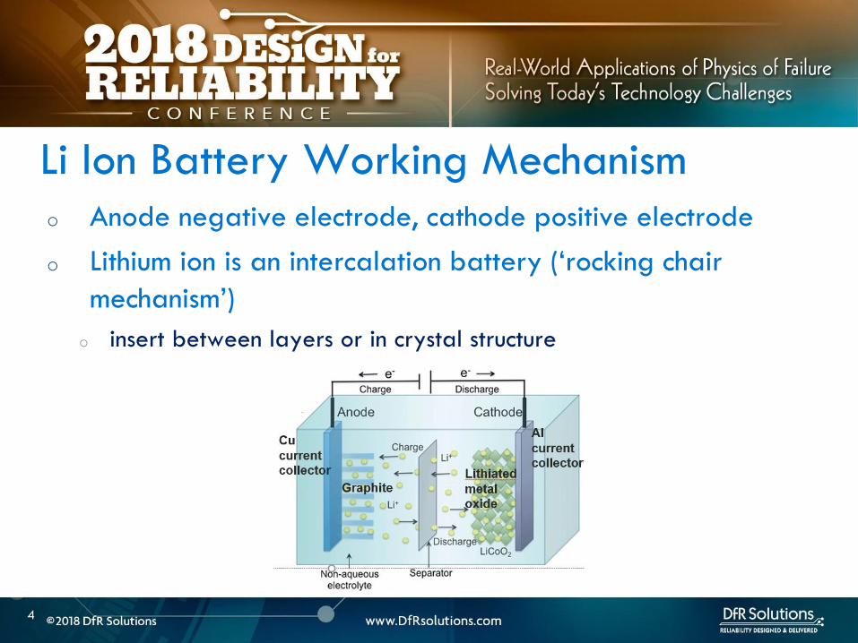

6
Samsung 2016 Battery Failures
6
Source Samsung Galaxy Note 7 failure investigation press conference Jan 2017 All Information in public domain
o Galaxy Note 7 fires were reported within a few weeks of the product launch
o Samsung recalled affected phones and pointed to a manufacturing error from its battery supplier Samsung SDI
o The batteries were swapped with ones from its Chinese supplier ATL
o Replacement phones that were supposed to be ldquofixedrdquo also started to catch on fire
o Samsung scrapped the entire product line 25 million phone recalls prior Cost Samsung $5 Billion
Samsung Galaxy 2016 Failures
7
Flattened Jellyroll Pouch Cell Design
8
o Damage to the negative electrode windings caused by
deflection by a pouch design that did not provide sufficient
volume to accommodate the electrode assembly
o Curvature of pouch causes deflection of the negative electrodes
Manufacturer A Root Cause
9
o Negative electrode damage provides multiple pathways to cell internal short circuit and thermal runaway under normal cycling conditions
o Damage to the separator
o Lithium plating
Negative Electrode Deflection
10
Source Information in public domain
Overcrowded Bus Analogy
11
o Tab welding defect created an internal short
Manufacturer B Root Cause
12
o Poorly controlled
welding process - Burr
height 80 microm in some
cases
o Normal swelling and
contraction occurs
during charge-
discharge cycling
o Some batteries were missing the insulation tape
o Samsung blames the flaws on its factories trying to get production started too quickly to counteract lost sales
o There are simply no short cuts when it comes to lithium ion battery manufacturing process control
Manufacturer B Root Cause
13
14
LITHIUM ION BATTERY
FAILURE MODES AND
MECHANISMS
14
LITHIUM ION BATTERY FAILURE MODES
15
Lithium Ion Battery Failures
Non-energetic
Failures Energetic Failures
Explosion
IR
Increase
Permanent
Safety Feature
Enabled
Cell
swelling
Electrolyte
leakage
Capacity
Loss
Fire Venting
o All non-energetic failures are not benign
o What dictates whether a failure is energetic or not
o Same initiating fault can have different outcomes
o Depends on whether the initiating fault can create a self-
sustaining exothermic reaction
BENIGN ENERGETIC AND NON-ENERGETIC
16
LITHIUM ION BATTERY FAILURE CAUSE
17
Elevated Cell
Temperature
Heat
Dissipatedgt
Heat
Generated
Heat
Dissipatedlt
Heat
Generated
Non-
energetic
Failures
Thermal
runaway
Overcharge
Overdischarge
High ambient temp
External short circuit
Internal short
circuit
Metallic ContaminationBurrsweld
defects
Lithium PlatingMechanical
damage
Low
Anodecathode
ratio
Anode delam
Low electrolyte
OutcomeCauseMitigation
Safety
electronics
and cell
internal
safety
features
Manufacturing
quality and
process control
Low temp
charging
Design
o Breakdown of passivating SEI layer on anode
o Excessive currents overcharging or high external ambient temp
o Starts at 80 C New SEI formed but at a higher uncontrolled rate in an
exothermic reaction Self accelerating reaction
o Electrolyte breakdown
o Organics in the electrolyte break down releasing flammable hydrocarbon
gases but no oxygen
o Typically around 110 -120 C
o Pressure starts to build up Even
if temp rises above flash point
no burning due to lack of oxygen
CELL REACTIONS AT ELEVATED TEMP -1
18
o Safety vent pops to prevent explosion (18650 metal can type) ndashnow have oxygen available
o Separator melting occurs around 155 C causing electrodes to short
o Further temperature rise causes metal oxide breakdown at cathode releasing oxygen in an exothermic reaction For Cobalt oxide this happens at 200 C
o Highly flammable organics elevated temp and oxygen
CELL REACTIONS AT ELEVATED TEMP -2
19
o Elevated temperature and cell failure are intricately tied together
o Elevated temperature negatively impacts capacity
o At higher rates higher capacity degradation
o 50 Loss in cycle life from 1 C to 12 C charging rate
o Cannot be explained by temperature rise alone
ELEVATED TEMP AND FAILURES
20
Choi S S amp Lim H S (2002) Factors that affect cycle-life and
possible degradation mechanisms of a Li-ion cell based on LiCoO2
Journal of Power Sources 111(1) 130-136
o Rapid performance degradation (sudden death) ndash lithium plating is highly reactive to electrolyte
o electrolyte and lithium consumption causing electrode dry out
o further lowering of anode to cathode ratio
o increased impedance and further risk of plating
o Safety issues ndash risk of dendritic growth exothermic reaction between plated lithium and electrolyte
LITHIUM PLATING ndash WHY IS IT BAD
21
Image source Safety of Lithium-Ion Batteries
Zhang et al Lithium-Ion Batteries
Advances and Applications
2014 Pages 409ndash435
o When does it happeno Operation outside specification window- overcharging high charging rate low temperature
(protection circuitry)
o Batteryapplication design ndash low anodecathode low electrolyte mechanical deformation from product (design engineeringquality)
o Manufacturing defects ndash eg anode delamination mechanical deformation poor quality cells (quality engineering)
LITHIUM PLATING
22
Image Source Understanding
undesirable anode lithium
plating issues in lithium-ion
batteries Liu et al RSC Adv
20166
LITHIUM ION SAFETY
23
Abuse Manufacturing Defects
Cell amp Application Design
Handling
Thermal Abuse
Electrical Abuse
Mechanical Abuse
2 90 5 3
bull BMS amp Circuitrybull Standardized Tests
Fiel
d F
ailu
re
Mit
igat
ion
Val
Fa
ilure
Cau
ses
Nea
r M
iss
Even
ts
0 50 25 25
Internal Shorts Cell Design
Application design
Storage
Assembly into host device
bull Quality Process Control
bull CT scansManuf audit
bull Design reviewsbull CT ScansApp
specific testing
bull Process and procedure review
bull Self discharge tests
User
24
Internal Shorts ndash lsquoSoft underbellyrsquo
Internal shorts are typically the result of manufacturing defects
and are not effectively mitigated by safety systems
There is no good internal short circuit test that effectively
screens out these defects
The best defense is to have sound manufacturing process
controls
24
25
Improper BMS Design
o Poorly designed BMS and use of improper chargers are
responsible for some of the spectacular field failures
o Over-voltage failures are more spectacular and immediate than
grown in manufacturing defects which can take time to manifest
themselves
o Battery protection system includes the charger circuitry
protection circuit module located at the battery and is
optimized for a specific cell chemistry and application
o Good BMS design should include use of a custom connector so that
everyday USB chargers canrsquot be plugged in and allowed to abuse the
cell
26
LITHIUM ION CELL
MANUFACTURING PROCESS
26
27
o Incoming raw materials
o Electrode fabrication and cell assembly
o Environmental control
MANUFACTURING CONTROLS
28
o Energy density
o Pack as much active material as possible
o Minimize fines which make wetting difficult and require more
solvent and lower the solids content in slurry
o Power density
o Higher void volumes lower
electrode pressed density
and thickness
POWER DENSITY VS ENERGY DENSITY
29
o Incoming powders ndash Tap density particle size distribution
(PSD) surface area purity
o Binders and binder solvents
o Separator
o Electrolyte
o Current collectors
o Dry room storage (dew point of at least -40 C) Dew point is
used to express water vapor concentration at this level because
the corresponding relative humidity value is less than 1
MANUFACTURING INCOMING RAW MATERIALS
Separator
ELECTRODE FABRICATION
30
QC -Viscosity and
dispersion control
Riskndash shorts unreacted
lumps cause risk of
dryout and plating
QC ndashthickness slurry
metering
Riskndash non-uniform
coating leading to
shorting risk dryout
QC ndash thickness
adhesion
Riskndash blisters lack of
adhesion leading to
lithium plating
QC ndash electrode
thickness oncehr roller
gap check 4-6 hrs
porosity Riskndashlack of
cell performance for
energy or power
QC ndashburr control
tension control cutting
wheel maintenance
Riskndashinternal shorts
CELL ASSEMBLY FORMATION AND TESTING
Battery Manufacturing (nd) Retrieved March 22 2017 from httpw3siemenscommarketsglobalenbattery-
manufacturingapplicationsprocesspagesdefaultaspx
WindingStacking
QC ndashalignment
Riskndashinternal shorts
Tab welding
QC ndash burrweld height
control
Risk ndash internal shorts
QC ndash Weight before and
after stringent moisture
control
Risk ndash electrode dryout and
plating swelling from
moisture
QC ndash OCV IR weight
dimension check prior to
formation Rest to allow
electrolyte wetting after
filling followed by
formation
QC ndash OCV IR weight
dimension followed by
aging qualification tests
32
o The process involves a multi-zone oven with low temperatures for the first zone higher temperatures for the middle zone followed by a lower temperature for the final zone
o Specific temperatures will depend on binder chemistry and on slurry properties
o For PVDF binder on the cathode the recommended drying oven temperature profile for a 5-zone oven is as follows zone 1 ndash 75-90 degC zones 2-4 ndash 125-130 deg C zone 5 ndashapproximately 75 deg C A 4-zone oven should run at slower speed to allow more solvent evaporation
DRYING TEMPERATURES
33
o Incoming materials control
o Internal specifications that identify minimize and control all known
and likely impurities in incoming materials
o Internal specifications that control material properties or specs
o Ability to track changes in vendor materials
GENERAL MANUFACTURING GUIDELINES
34
o Manufacturing process control
o Safety critical equipment must be identified - process of verifying
equipment operation periodically Preventive maintenance plan
implementation
o Procedures to avoid metal contamination throughout the manufacturing
process
o Processes to collect loose material such as coating dust
o A method of detecting mechanical damage to electrodes in the
manufacturing process such as an automated vision system
o Statistical process control (SPC) to monitor maximum particle size slurry
viscosities coating weight calendered thickness weight of electrolyte
dispensed cell weight open circuit voltage (OCV) and capacity
GENERAL MANUFACTURING GUIDELINES
35
o Robust environmental control with a specific focus keeping ambient moisture minimized
o Destabilizes SEI layer and electrolyte and causes gassing
ENVIRONMENTAL CONTROL
36
LITHIUM ION CELL DESIGN
GUIDELINES
36
37
o Anode should overhang cathode by 05 mm or more on all sides for stacked cell or along top and bottom ends for jellyroll (min of 01 mm per IEEE 16251725)
o Anode should have higher electrochemical capacity than cathode by 10-15
o Example 1 g anode specific capacity is 350 mAhg So total anode capacity is 350 mAh
o 1 g cathode with specific capacity of 280 mAhg has total capacity of 280 mAh
Cathode shall never put out more lithium
ions than the anode can accommodate
CELL DESIGN GUIDELINES
Cathode
Separator
Anode
38
o Separator overhangs anode on all sides (room temperature to
at least 110 C- IEEE 16251725)
o Less than 5 shrinkage in both machine and transverse
directions at 90 C as a minimum
o Separator should have sufficient mechanical
strength to withstand cell assembly operations
CELL DESIGN GUIDELINES
Cathode
Separator
Anode
39
o Product design ndash make sure there is enough room for battery to
expand as it goes through charge ndashdischarge cycles Recommend 10
margin
o Pay particular attention to corners
o Poor manufacturing can reduce design margin
o Cutting operation variability
o Pick and place variability
CELL DESIGN GUIDELINES
40
ARTICLE QUALITY ASESSMENT
CELL CT SCANS AND
TEARDOWN
40
41
o Deep discharged cell
ARTICLE QUALITY ASESSMENT ndash CT SCANS
42
o Exercise - Describe what you see
o Electrode alignment is good on right image
o Variability in jellyroll winding on left and middle images
o Insufficient anode overlap in center of middle image
ARTICLE QUALITY ASESSMENT- CT SCANS
43
o Conduct CT scans and cell teardowns on a handful of units
o What to look for in CT scans
o Uniform cell winding or stacking
o No particulates
o No significant electrode delamination
o Anodes should overhang cathode by 05 mm ideally but a minimum
of 01 mm on each side
o No excessive deformation at pouch corners
o Cutting operationpick and place variability
PHYSICAL ARTICLE QUALITY ASESSMENT ndash CT SCANS
44
o Look at a few electrode pieces using optical microscopy
and SEMEDS
ARTICLE QUALITY ASESSMENT ndash TEARDOWNS
45
LITHIUM ION INTERNAL
AND EXTERNAL
PROTECTION SYSTEMS
45
o Positive Temperature Coefficient (PTC) device - inhibit high current surges
o Charge interrupt device (CID)- opens the electrical path if an excessively high charge voltage raises the internal cell pressure to a threshold value
o Safety vent- allows a controlled release of gas in the event of a rapid increase in cell pressure
o Hot electrolyte vapors and gas will always blow towards the burst disc instead of splitting the sides
o Shutdown Separators
CELL SAFETY PROTECTION MECHANISMS
46
o PTC - doughnut shaped device that sits between two metal
plates and is made of a polymeric material
o At high currents or temperatures resistance of the PTC increases
sharply causing the current to drop
PTC DEVICE
47
Image source nasagov
o The PTC is resettable and reverts
back after the fault is removed
o Once activated it subsequently
activates at a lower current and
temperature
o Works by releasing the connection at the positive terminal and
opening the electrical path
o Pressure valve which will disable the cell permanently of
pressure in the cell is too high
o Is not resettable
CHARGE INTERRUPT DEVICE
48
Image source nasagov
o Pouch cells do not have an internal CID PTC or safety vent
o Can have PTC or fuse elements in series with cell
POUCH CELL PROTECTION
49
Image source nasagov
50
o Separator is usually made of polyethylene (PE) polypropylene (PP) or a combination of the two
o Inner PE layer shuts down at 130degC by closing the pores the outer PP layers do not melt until reaching 155degC
SHUTDOWN SEPARATOR
Image Source Battery University
51
o Separator should increase its resistance by two orders of
magnitude at shutdown temperature (typically 130 C)
SHUTDOWN CURVES
Image Source Arora and Zhang Battery Separators Chem Rev 2004 104 (10) pp 4419ndash4462
52
o Know separator propertieso Thickness
o single vs multiple layer (PE PP or combination)
o ceramic coated or not
o Ceramic coatings can enhance thermal stability and prevent separator collapse till 200 C and beyond
o Ceramic coated separators usually may not have the mechanical strength to withstand winding and assembly- irrelevant for prismatic or stacked designs
SHUTDOWN SEPARATOR PROPERTIES
Impedance (1 kHz AC) vs Shutdown temperature of electrolyte soaked separators (ab) Polyethylene and (c)
polypropylene
53
BATTERY MANAGEMENT
SYSTEM (BMS) AND
PROTECTION CIRCUITRY
53
54
o Operating outside of specifications
Operating Outside Specifications
Image source Electropaedia
55
o Depends on a number of factors
o State of charge (SOC)
o Ambient temperature
o Cell chemistry
o Cell design
o Most severe thermal runaway occurs in an overcharged state
o Case temperatures can reach 600 C
o High temperatures are driven by exothermic reactions of the electrodes and the electrolyte
Severity of Thermal Runaway
56
o Self heating temperature o Fully charged 18650 cells brought to self heating temperature
(70 to 90 C) in adiabatic environment go into thermal runaway in 2 days
o Fully charged 18650 in adiabatic environment brought to 150 C (with separator melting) will run away in minutes
o UL standard requires fully charged cells to withstand 4 hour storage at 75 C and 10 min storage at 130 C
o IEEE standard requires 1 hour exposure at 130 C
o Overcharge o Charging a 42 V system to 5 V will almost certainly cause
immediate thermal runaway
Thermal Runaway Initiation ndash Some Numbers
57
o EV electric bus caught fire in Shenzhen China during
charging
o BMS Failure
o Without a BMS there is no
safe lithium ion battery
EV Bus Failure
58
o Consist of charger and a battery protection printed circuit board (PCB)
o Also called a battery protection circuit module (PCM)
o Important functions of protection systems include monitoring controlling and terminating charge and discharge as needed
o Failure of protection circuitry to either sense or respond to an out of range condition causes battery failure
ELECTRONIC PROTECTION SYSTEMS
59
o Maintain cells within operating window and prevent cells
from going into
o Over voltage
o Over current
o Over temperature
o Over discharge
o Balance individual cells to enhance overall capacity
o Disconnect batteries in a safe way in emergency situations
o Predict remaining capacity or state of charge
BMS FUNCTIONS
BMS Webinar httpswwwdfrsolutionscombattery-management-systems-and-safety-and-reliability-webinar
60
o Most obvious failure mode is exceeding specified voltage
o Charging a 42 V system to 5 V will almost certainly cause immediate thermal runaway
o Charging at excess currents
o Overcharge effects
o Anode ndash lithium plating rather than intercalation
o Cathode ndashexcess de-intercalation causes crystal structure to collapse and release heat
o Heat and gas release (both Joule heating and parasitic reactions)
o Electrolyte and electrode decomposition
OVER CHARGE - VOLTAGE
61
o Over voltage may be applied to the battery from a defective charger or due to improper monitoring on a single cell
o Slight overcharge (from minor deviations in voltage monitoring) causes capacity loss rather than direct thermal runaway
o Overvoltage protection can be implemented by opening a charge MOSFET or a fuse
o Overcharge protection is so critical that multiple independent circuits are typically used to prevent single points of failure
OVER VOLTAGE
62
o Hazard from over discharge is highly underestimated
o When a cell goes into deep discharge copper ions from the negative electrode current collector dissolve On recharge copper dendrites can form
o Over discharge can also cause breakdown of the SEI layer and gas formation
OVER DISCHARGE
Image Source Rui Guo1 Languang
Lu1 Minggao Ouyanga1 and Xuning
Feng1 Sci Rep 2016
63
How Does a Battery Go into
Deep Discharge
63
64
o Uncontrolled storage without appropriate recharge
procedures
o Mechanically damaged cells (from electronics impinging
on cell)
OVER DISCHARGE SCENARIOS
65
o Three kinds of discharge occur during storage o PCM sleep current and leakage currents
o Battery self discharge
o Manufacturing quality
o Temp
o State of charge
o Device sleep currents
o At 3 V (or other threshold cutoff) load is disconnected although above lsquoconsumption currentsrsquo are active
o At deep discharge cutoff value of 2 V (or other manufacturer specified value) PCM and device sleep currents are turned off but battery self discharge continues
Discharge During Storage
66
o Lithium ion self discharge around 1-2 per month + a
few cent for PCM
o High SOC and temperatures degrade storage life (and
cycle life)
o Rule of thumb ndash 10 C increase in temperature doubles self
discharge rate
o Store at conditions close to 25 C and 40 SOC
Battery Self Discharge
67
o To keep the contamination as low as possible to reduce
leakage current de-ionized water wash should be used
in the board cleaning process
o Verify the board cleanliness to make sure the levels of
contamination is low
o Investigate if humidity is an issue and that conformal
needs to be used
PCM (BMS) Self Discharge
68
o Have a pre-check charging function on batteries where deep discharge cutoff voltage was reached Charger circuit checks if a deeply discharged battery is reaches a threshold value in give time Otherwise considered a lsquodamagedrsquo battery
o Mitigating hazard from copper shunts
o Proper battery storage and recharge procedures
o Minimize PCM leakage currents
o Ensure cell quality
o Prevent cell mechanical damage
Deep Discharge Checklist
69
o Over current can causeo Degradation in cycle life
o Thermal runaway
o Threshold limits for current are functions of both current and time Protection circuit system can use different combinations of time and current to produce a fault Example - high currentshort time or lower currentlong time
o Some faults are recoverable such as when a MOSFET is turned on and others are non-recoverable such as when a fuse is ignited
o Causes of over-current could be a defective charger or due to an internal short
OVER CURRENT PROTECTIONS
70
o A good battery management system will limit charge current and voltage at high and low temperature extremes per Japan Electronics and Information Technology Industries Association (JEITA) guidelines
OVER CURRENT
(60 degC)
CoolCold Warm Hot
(0 degC)
Reduce charging
current andor
voltage
Reduce charging
current andor
voltage
71
o Current limits are incorporated into the protection
circuits located in pack or device
o Circuits monitor current in and out of battery and open up
MOSFET to interrupt current
o Backup protection usually includes a fuse or PTC placed
in series with battery pack
SHORT CIRCUIT PROTECTION
72
BATTERY LIFE DEGRADATION
AND STORAGE
72
73
o Battery life example
o Nominal capacity is 2900 mAh End of life capacity at 80 of initial capacity is 2300 mAh
o Is this data sufficient to give you a life of 500 cycles
BATTERY LIFE AND AGING ISSUES
74
o Calendar aging vs cycle life agingo Insertion or ejection of the Lithium ions into and out of the intercalation
spaces during cycling causes the electrode materials to swell or contract
o Repetitive cycling can weaken the electrode structure reducing its adhesion to the current collector This can lead to reduction in charge capacity
BATTERY LIFE DEGRADATION
75
o Storage degradation high temperature aging causes
growth of the passivating layer
o It consumes lithium and electrolyte and leads to capacity loss
and impedance increase (both capacity and power fade)
Pores can be blocked as a result
o Low rate batteries may not see a big impact
(voltage drop = IR)
BATTERY LIFE DEGRADATION CALENDAR AGING
76
o Have two distinct mechanisms
that impact cell life
o Battery aging tests should
involve high temperature
storage tests
BATTERY LIFE DEGRADATION CALENDAR AGING
Image source Electropaedia
77
o Characterize both reversible and irreversible storage loss
o In this example 25 irreversible and 5 reversible
capacity loss
REVERSIBLE VS IRREVERSIBLE STORAGE LOSS
Assume a = 2900 mAh
d = 70 a = 2030 mAh
e = 95 a = 2700 mAh
a
d
e
78
LITHIUM ION CHEMISTRIES
78
79
o Term Lithium-Ion encompasses many different chemistries
o Anode ndash graphite (Lithium Titanate LTO for very fast charge cells)
o Cathode - Cathodes are lithiated metal oxides or lithiated metal
phosphates
o Lithium Cobalt Oxide (LCO)
o Lithium Iron Phosphate(LFP)
o Nickel Manganese Cobalt (NMC)
o Lithium Manganese Oxide(LMO)
o Cathode chemistry is where you get enhancements in safety
energy and power density
Battery Chemistry
80
o Lithium Cobalt Oxide (LCO) ndash commonly used in consumer electronics
o High energy density
o Low power
o Least safe
o Moderate cycle life
Battery Chemistry
o Lithium Iron Phosphate(LFP) ndashndash automotive power tools UPS e-cigs
o Safest chemistry
o High power density
o Very high cycle life
o Lower voltageLower energy density
o Higher self discharge rate
81
o Nickel Manganese Cobalt (NMC) ndashcommon in tools EV applications
e-cigs ndash usually 13 proportion but customization is possible
o Can be optimized for power or energy
o Good safety
o Good cycle life
Battery Chemistry
o Lithium Manganese Oxide(LiMn2O4) ndashndash power tools EV and hybrid vehicles e-cigs
o Low internal resistancehigh power capability (from Manganese)
o Good safety
o Lower energy ndash blends with NMC are used to enhance energy
82
Battery Chemistry Summary
Chemistry LCO NMC LFP LMO
Nominal Voltage(V) 36-37 36-37 32-32 36-37
Charge Voltage(V) 42 42 35-36 42
Safety Poor Good Highest Good
Cycle Life gt500 gt500 gt1000 gt500
Peak Load current (Best result) 2C
(lt1C)
gt30C
(lt10 C)
gt30C
(lt10 C)
Specific energy (WhKg) 150-250 90-120 100-150
Thermal Runaway Temp (ordmC) 150 210 gt270
Used Since 1991 2003 1999 1996
Designation ICR INR IFR IMR
o Knowing chemistry helps to map out worst case scenario
o For pouch cells look at MSDS
83
o Do not see the word LCO
Battery Chemistry in Current EV Systems
84
ESTIMATING STORED ENERGY
84
85
o Risk assessment
o How much energy and wattage does the battery have
o How fast is the energy released
o Is the product worn on or close to the body
o What is the chemistry
o New product category Are there specific user behaviorsproduct
design interactions that increase the risk and impact of thermal away
o Risk mitigation
o Trust but verify
o Do not trust till you verify
o Map out the worst case
BATTERY RISK ASESSMENT
86
o Stored energy is a combination of electrical and chemical
energy
o Electrical Energy
o Chemical energy may be approximated by using heats of
combustion of various flammable components in cell
STORED ENERGY
87
o Specification
o 37 V
o 296 Wh
o 800 mAh
o Useful information 1 Wh = 36 kJ
o Total stored energy = 296 36 = 1065 kJ
STORED ENERGY PRISMATIC EXAMPLE
88
o Assume 1 to 5 g of electrolyte for small prismatic or pouch cell Assume 05 to 1 g of separator
o Electrolyte solvents are generally organic carbonates such as diethyl carbonate (DEC) ethylene carbonate dimethyl carbonate and ethylmethyl carbonate
o Using the heat of combustion of DEC at 2092 kJg 21 to 105 kJ of energy from electrolyte combustion
o Separator is made of polyethylene polypropylene or combination of the two
o By using polypropylene heat of combustion as an approximation at 4266 kJg 21 to 42 kJ energy for the separator
o Total chemical energy approximation is 42 to 147 kJ
STORED CHEMICAL ENERGY SMALL PRISMATIC
89
o Estimate of total energy released is 52 to 117 kJ
STORED ENERGY SMALL PRISMATIC
Cell Type Energy Low (kJ) High (kJ) Amount (g)
Chemical Energy Combustible
materials Total
42 147
Separator 21 42 05 to 1
Electrolyte 21 105 1 to 5
Electrical (nominal voltage to fully
charged state)
1065 121
Prismatic Total 5265 117
90
o Specification o 37 V
o 962 Wh
o 2600 mAh
o Useful information 1 Wh = 36 kJo Heat of combustion of DEC = 2092 kJg
o Polypropylene heat of combustion = 4266 kJg
o For comparison a 190 g stick of dynamite can release 1 MJ of energy1
STORED ENERGY 18650 EXAMPLE SOLUTION
Cell Type Energy Low (kJ) High (kJ) Amount (g)
Chemical Energy Combustible materials Total 122 23561
Separator 5972 6825 14 to 16
Electrolyte 6236 16736 3 to 8
Electrical (nominal voltage to fully charged
state)
3462 393
18650 Total 157 207
1 httpsenwikipediaorgwikiDynamite
91
Is the 18650 Hazard
Relevant to You
91
92
o Smaller batteries - 20 mAh to 500 mAh
o Energy released is 10- to 100 times lower than the 18650o Smaller capacity batteries release smaller amounts of energy
o 150 -200 mAh batteries generally used for headphone applications such as in illustration
Small Batteries
93
o Calculate total energy released from your cell
o Electrical energy + chemical energy
o Use thermal analysis to estimate temperature rise and
compare against allowable surface temperaturesstandards
Worst Case Analysis
Material Burn Threshold for
contact of 05 s (ordmC)
Bare metal 67-73
Ceramics glass and stone 84-90
Plastics 91-99
Wood 128-155
European standard BS EN 132022000
94
o Potential for burn hazard may be estimated
Skin Burn Temperatures
Effect Description Skin
Temperature
(ordmC)
Pain Tingling hot sensation 44
1st degree burn Superficial injury to outer layer skin
is reddened painful
44-55
2nd degree burn Outer layer is burned through
second layer damaged skin is moist
and reddened with blisters intense
pain
55-60
3rd degree burn All skin layers are damaged 60
95
VENT GAS RISK
95
96
o Vent gases mainly consist of H2 hydrocarbons (also called THC or
total hydrocarbon concentration in figure below) CO2 and CO
o Flammable gases include H2 CO and hydrocarbons
Vent Gas Flammability
Ref 1 US DOTFAA Study Lithium Battery Thermal Runaway Vent Gas Analysis Nov 2016
Major gas species concentration for18650 LiCoO2 cell
97
o When a lithium ion battery vents the gas mixture will mix with surrounding air and may or may not ignite
o The following conditions have to be met for an ignition evento Air fuel mixture is within the Lower Flammability Limit (LFL) and (Upper
Flammability Limit) UFL limits
o Ignition source is present
o The most dangerous materials are those with the lowest flash point and widest flammable ranges
o A hot cell case or hot metal sparks ejected from the cell could create an ignition event if the mixture is within flammability limits
Ignition Risk
98
CHEMICAL SPILL RISK
98
99
o In the absence of a fire potential hazard from a damaged lithium ion battery includes the following
o Release of a electrolyte containing a corrosive salt Electrolyte is extremely corrosive and may cause permanent blindness If ingested through the mouth liver and kidney damage is possible
o Reaction of the electrolyte with waterhumidity may generate hydrofluoric acid which are highly toxic and corrosive to the eyes nose throat and skin
o Release of volatile organics toxic gases such as CO HF
Chemical Spill Risk
Ref Various MSDS sheets
100
o Lithiated carbon in a charged anode the Solid Electrolyte
Interphase (SEI) layer or any free lithium (dendritesplating)
will burst into flames when exposed to moist air
o Reaction of lithium with water produces H2 in an exothermic
reaction
o Significant heat is released in this reaction and this can ignite the H2
Chemical Risk ndash Lithium Ion and Primary Lithium
101
Lithium Ion Life Cycle ndash
Cradle to Grave
101
102
o Cell Manufacturing
o brought to a low to moderate state of charge for shippingstorage
o Transportation
o Warehouse storage
o Pack or device assembly
o OEM device shipment
o Device Usage
o Recycling
LITHIUM ION BATTERY LIFE CYCLE
103
o Almost all failures are related to improper packaging (potential for mechanical damage and external shorts) and shipment procedures
o International Air Transportation Association (IATA) shipment procedures for dangerous goods Cell manufacturers must show proof of UN 383 certification
o 1) Lithium ion batteries (not contained in equipment) shall not be shipped with SOC greater than 30
o 2) Shall pass UN 383 battery of tests
o 3) Shall not be shipped on passenger aircraft
Transportation Procedures
See httpwwwiataorgwhatwedocargodgrDocumentslithium-battery-shipping-guidelinespdf
104
o Small cell shipment exceptions to class 9 dangerous goods classification
o Only Carry-on and Section II are exempt from Class 9 hazardous material
designation
Transportation Procedures
Image source
Battery university
105
o Have procedures in place for safe handling of lithium ion
batteries
o Protection from short circuit high temperature is critical
o Pouch cells must use recessed packaging trays
Storage and Warehouse Handling
106
o Do not single stream recycle lithium ion batteries
o High risk of ignition with surrounding paper and cardboard
o Lithium Ion batteries can be recycled but only at specified
locations Visit httpswwwcall2recycleorglocator
(Rechargeable Battery Recycling Corporation)
o 86 of US and Canadian residents live within 10 miles of
drop-off location
o httpswwwcall2recycleorg for battery recycling resources
Lithium Ion Recycling Procedures
107
o Do not discard as trash
o When collecting batteries make sure they are taped or
insulated
o Recommend drop-off instead
Lithium Ion Recycling Procedures
108
COMPLIANCE TESTING
108
109
o Tests that have the same name under different standards are not always the same
o There are differences in terms of the state of charge aging of the cells and sample sizes and these can have significant differences
o The vendor must state the test standard specify a test description in addition to the name of the test
BATTERY COMPLIANCE TESTING
110
o UNDOT 383 Covers transportation safety testing for all lithium
metal and lithium ion cells and batteries This is mandatory
o UL safety standards
o UL 1642 ndash This standard is used for testing lithium cells Battery level tests
are covered by UL 2054
o UL 2054 (Household and Commercial Batteries) ndash For lithium batteries UL
2054 defers all component cell level testing to UL 1642
o CEIIEC 62133 ndash this standard is voluntary in the US but some
countries specify this standard
BATTERY COMPLIANCE TESTING
111
o IEEE 16251725 ndash These standards are applicable to rechargeable batteries for Multi-cell mobile computing devices and for Cellular phones respectively (CTIA or Wireless Association)
o These standards take the most comprehensive approach to battery testing and emphasize that battery pack safety is a function of a) the individual cells b) the battery pack c) the host device d) power supply accessories e) the user f) the environment
o Both standards require design analysis tools such as FMEA or fault tree analysis They also encompass industry best practices in manufacturing and in the areas of cell pack system and charging accessory design
BATTERY COMPLIANCE TESTING
112
The more you know the better
Parting Thought
Questions
bull Contact Vidyu Challa
vchalladfrsolutionscom
301-640-5834
bull wwwdfrsolutionscom resources page for
battery and other electronic reliability
resources
114
APPENDIX
114
115
Battery Seal Quality
o Moisture ingress through
o Laminate face (extremely low due to metal barrier)
o Interfaces (no metal barrier)
o Terminals (good sealing practices mandatory)
o Compensate through large seal width ( generally 2 mm
min)
o Seal width checks
116
o Flash points for common components of lithium ion battery
electrolytes are below
FLASH POINTS
Ref CRC handbook of chemistry and physics
Electrolyte Component Boiling Point Flash Point
Propylene carbonate (PC) 242degC 135degC
468degF 275degF
Ethylene carbonate (EC) 248degC 145degC
478degF 293degF
Di-Methyl carbonate (DMC) 91degC 18degC
195degF 64degF
Diethyl carbonate (DEC) 126degC 25degC
259degF 77degF
Ethyl methyl carbonate (EMC) 107degC 25degC
225degF 77degF
117
o Flammability limits for vent gases from Li Ion batteries are in
table below
Ref Combustion Flames and Explosion of Gases 2nd Edition Academic Press NY 1961
Compound Lower flammability limit
(fuel volume )
Upper flammability limit
(fuel volume )
Hydrogen 40 750
Carbon monoxide 125 740
Methane 53 150
Ethylene 31 320
Ethane 30 125
Propylene 24 103
C4 hydrocarbons ~ 16-19 ~ 84 ndash 97
C5 hydrocarbons ~ 14-15 ~ 75 ndash 87
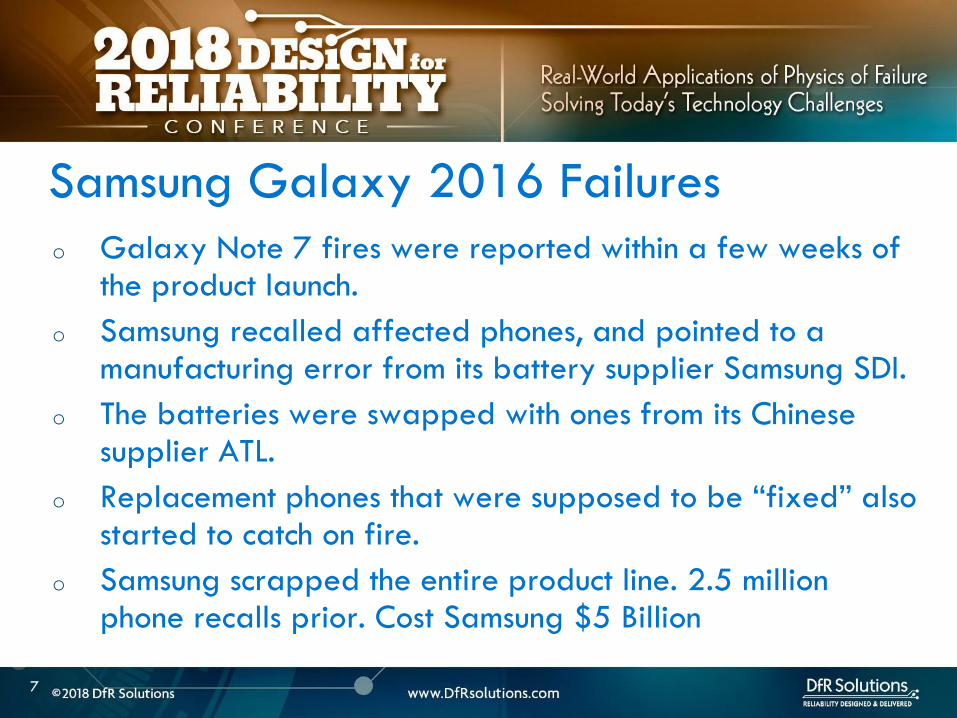
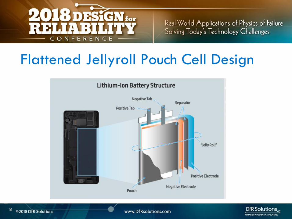
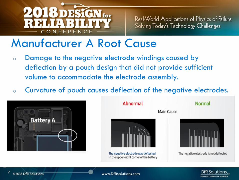
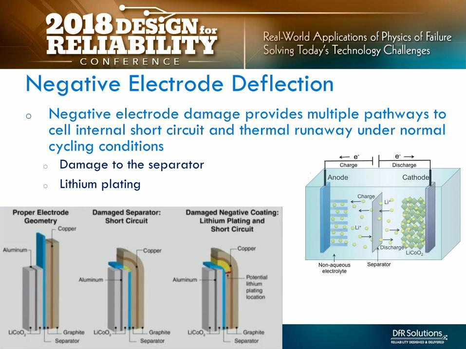
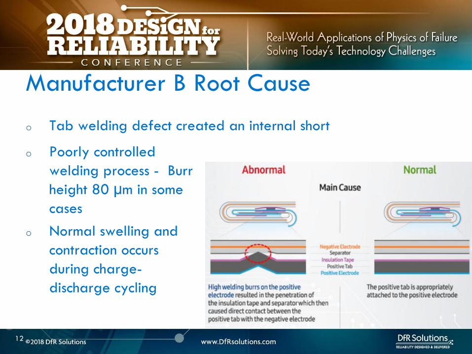

14
LITHIUM ION BATTERY
FAILURE MODES AND
MECHANISMS
14
LITHIUM ION BATTERY FAILURE MODES
15
Lithium Ion Battery Failures
Non-energetic
Failures Energetic Failures
Explosion
IR
Increase
Permanent
Safety Feature
Enabled
Cell
swelling
Electrolyte
leakage
Capacity
Loss
Fire Venting
o All non-energetic failures are not benign
o What dictates whether a failure is energetic or not
o Same initiating fault can have different outcomes
o Depends on whether the initiating fault can create a self-
sustaining exothermic reaction
BENIGN ENERGETIC AND NON-ENERGETIC
16
LITHIUM ION BATTERY FAILURE CAUSE
17
Elevated Cell
Temperature
Heat
Dissipatedgt
Heat
Generated
Heat
Dissipatedlt
Heat
Generated
Non-
energetic
Failures
Thermal
runaway
Overcharge
Overdischarge
High ambient temp
External short circuit
Internal short
circuit
Metallic ContaminationBurrsweld
defects
Lithium PlatingMechanical
damage
Low
Anodecathode
ratio
Anode delam
Low electrolyte
OutcomeCauseMitigation
Safety
electronics
and cell
internal
safety
features
Manufacturing
quality and
process control
Low temp
charging
Design
o Breakdown of passivating SEI layer on anode
o Excessive currents overcharging or high external ambient temp
o Starts at 80 C New SEI formed but at a higher uncontrolled rate in an
exothermic reaction Self accelerating reaction
o Electrolyte breakdown
o Organics in the electrolyte break down releasing flammable hydrocarbon
gases but no oxygen
o Typically around 110 -120 C
o Pressure starts to build up Even
if temp rises above flash point
no burning due to lack of oxygen
CELL REACTIONS AT ELEVATED TEMP -1
18
o Safety vent pops to prevent explosion (18650 metal can type) ndashnow have oxygen available
o Separator melting occurs around 155 C causing electrodes to short
o Further temperature rise causes metal oxide breakdown at cathode releasing oxygen in an exothermic reaction For Cobalt oxide this happens at 200 C
o Highly flammable organics elevated temp and oxygen
CELL REACTIONS AT ELEVATED TEMP -2
19
o Elevated temperature and cell failure are intricately tied together
o Elevated temperature negatively impacts capacity
o At higher rates higher capacity degradation
o 50 Loss in cycle life from 1 C to 12 C charging rate
o Cannot be explained by temperature rise alone
ELEVATED TEMP AND FAILURES
20
Choi S S amp Lim H S (2002) Factors that affect cycle-life and
possible degradation mechanisms of a Li-ion cell based on LiCoO2
Journal of Power Sources 111(1) 130-136
o Rapid performance degradation (sudden death) ndash lithium plating is highly reactive to electrolyte
o electrolyte and lithium consumption causing electrode dry out
o further lowering of anode to cathode ratio
o increased impedance and further risk of plating
o Safety issues ndash risk of dendritic growth exothermic reaction between plated lithium and electrolyte
LITHIUM PLATING ndash WHY IS IT BAD
21
Image source Safety of Lithium-Ion Batteries
Zhang et al Lithium-Ion Batteries
Advances and Applications
2014 Pages 409ndash435
o When does it happeno Operation outside specification window- overcharging high charging rate low temperature
(protection circuitry)
o Batteryapplication design ndash low anodecathode low electrolyte mechanical deformation from product (design engineeringquality)
o Manufacturing defects ndash eg anode delamination mechanical deformation poor quality cells (quality engineering)
LITHIUM PLATING
22
Image Source Understanding
undesirable anode lithium
plating issues in lithium-ion
batteries Liu et al RSC Adv
20166
LITHIUM ION SAFETY
23
Abuse Manufacturing Defects
Cell amp Application Design
Handling
Thermal Abuse
Electrical Abuse
Mechanical Abuse
2 90 5 3
bull BMS amp Circuitrybull Standardized Tests
Fiel
d F
ailu
re
Mit
igat
ion
Val
Fa
ilure
Cau
ses
Nea
r M
iss
Even
ts
0 50 25 25
Internal Shorts Cell Design
Application design
Storage
Assembly into host device
bull Quality Process Control
bull CT scansManuf audit
bull Design reviewsbull CT ScansApp
specific testing
bull Process and procedure review
bull Self discharge tests
User
24
Internal Shorts ndash lsquoSoft underbellyrsquo
Internal shorts are typically the result of manufacturing defects
and are not effectively mitigated by safety systems
There is no good internal short circuit test that effectively
screens out these defects
The best defense is to have sound manufacturing process
controls
24
25
Improper BMS Design
o Poorly designed BMS and use of improper chargers are
responsible for some of the spectacular field failures
o Over-voltage failures are more spectacular and immediate than
grown in manufacturing defects which can take time to manifest
themselves
o Battery protection system includes the charger circuitry
protection circuit module located at the battery and is
optimized for a specific cell chemistry and application
o Good BMS design should include use of a custom connector so that
everyday USB chargers canrsquot be plugged in and allowed to abuse the
cell
26
LITHIUM ION CELL
MANUFACTURING PROCESS
26
27
o Incoming raw materials
o Electrode fabrication and cell assembly
o Environmental control
MANUFACTURING CONTROLS
28
o Energy density
o Pack as much active material as possible
o Minimize fines which make wetting difficult and require more
solvent and lower the solids content in slurry
o Power density
o Higher void volumes lower
electrode pressed density
and thickness
POWER DENSITY VS ENERGY DENSITY
29
o Incoming powders ndash Tap density particle size distribution
(PSD) surface area purity
o Binders and binder solvents
o Separator
o Electrolyte
o Current collectors
o Dry room storage (dew point of at least -40 C) Dew point is
used to express water vapor concentration at this level because
the corresponding relative humidity value is less than 1
MANUFACTURING INCOMING RAW MATERIALS
Separator
ELECTRODE FABRICATION
30
QC -Viscosity and
dispersion control
Riskndash shorts unreacted
lumps cause risk of
dryout and plating
QC ndashthickness slurry
metering
Riskndash non-uniform
coating leading to
shorting risk dryout
QC ndash thickness
adhesion
Riskndash blisters lack of
adhesion leading to
lithium plating
QC ndash electrode
thickness oncehr roller
gap check 4-6 hrs
porosity Riskndashlack of
cell performance for
energy or power
QC ndashburr control
tension control cutting
wheel maintenance
Riskndashinternal shorts
CELL ASSEMBLY FORMATION AND TESTING
Battery Manufacturing (nd) Retrieved March 22 2017 from httpw3siemenscommarketsglobalenbattery-
manufacturingapplicationsprocesspagesdefaultaspx
WindingStacking
QC ndashalignment
Riskndashinternal shorts
Tab welding
QC ndash burrweld height
control
Risk ndash internal shorts
QC ndash Weight before and
after stringent moisture
control
Risk ndash electrode dryout and
plating swelling from
moisture
QC ndash OCV IR weight
dimension check prior to
formation Rest to allow
electrolyte wetting after
filling followed by
formation
QC ndash OCV IR weight
dimension followed by
aging qualification tests
32
o The process involves a multi-zone oven with low temperatures for the first zone higher temperatures for the middle zone followed by a lower temperature for the final zone
o Specific temperatures will depend on binder chemistry and on slurry properties
o For PVDF binder on the cathode the recommended drying oven temperature profile for a 5-zone oven is as follows zone 1 ndash 75-90 degC zones 2-4 ndash 125-130 deg C zone 5 ndashapproximately 75 deg C A 4-zone oven should run at slower speed to allow more solvent evaporation
DRYING TEMPERATURES
33
o Incoming materials control
o Internal specifications that identify minimize and control all known
and likely impurities in incoming materials
o Internal specifications that control material properties or specs
o Ability to track changes in vendor materials
GENERAL MANUFACTURING GUIDELINES
34
o Manufacturing process control
o Safety critical equipment must be identified - process of verifying
equipment operation periodically Preventive maintenance plan
implementation
o Procedures to avoid metal contamination throughout the manufacturing
process
o Processes to collect loose material such as coating dust
o A method of detecting mechanical damage to electrodes in the
manufacturing process such as an automated vision system
o Statistical process control (SPC) to monitor maximum particle size slurry
viscosities coating weight calendered thickness weight of electrolyte
dispensed cell weight open circuit voltage (OCV) and capacity
GENERAL MANUFACTURING GUIDELINES
35
o Robust environmental control with a specific focus keeping ambient moisture minimized
o Destabilizes SEI layer and electrolyte and causes gassing
ENVIRONMENTAL CONTROL
36
LITHIUM ION CELL DESIGN
GUIDELINES
36
37
o Anode should overhang cathode by 05 mm or more on all sides for stacked cell or along top and bottom ends for jellyroll (min of 01 mm per IEEE 16251725)
o Anode should have higher electrochemical capacity than cathode by 10-15
o Example 1 g anode specific capacity is 350 mAhg So total anode capacity is 350 mAh
o 1 g cathode with specific capacity of 280 mAhg has total capacity of 280 mAh
Cathode shall never put out more lithium
ions than the anode can accommodate
CELL DESIGN GUIDELINES
Cathode
Separator
Anode
38
o Separator overhangs anode on all sides (room temperature to
at least 110 C- IEEE 16251725)
o Less than 5 shrinkage in both machine and transverse
directions at 90 C as a minimum
o Separator should have sufficient mechanical
strength to withstand cell assembly operations
CELL DESIGN GUIDELINES
Cathode
Separator
Anode
39
o Product design ndash make sure there is enough room for battery to
expand as it goes through charge ndashdischarge cycles Recommend 10
margin
o Pay particular attention to corners
o Poor manufacturing can reduce design margin
o Cutting operation variability
o Pick and place variability
CELL DESIGN GUIDELINES
40
ARTICLE QUALITY ASESSMENT
CELL CT SCANS AND
TEARDOWN
40
41
o Deep discharged cell
ARTICLE QUALITY ASESSMENT ndash CT SCANS
42
o Exercise - Describe what you see
o Electrode alignment is good on right image
o Variability in jellyroll winding on left and middle images
o Insufficient anode overlap in center of middle image
ARTICLE QUALITY ASESSMENT- CT SCANS
43
o Conduct CT scans and cell teardowns on a handful of units
o What to look for in CT scans
o Uniform cell winding or stacking
o No particulates
o No significant electrode delamination
o Anodes should overhang cathode by 05 mm ideally but a minimum
of 01 mm on each side
o No excessive deformation at pouch corners
o Cutting operationpick and place variability
PHYSICAL ARTICLE QUALITY ASESSMENT ndash CT SCANS
44
o Look at a few electrode pieces using optical microscopy
and SEMEDS
ARTICLE QUALITY ASESSMENT ndash TEARDOWNS
45
LITHIUM ION INTERNAL
AND EXTERNAL
PROTECTION SYSTEMS
45
o Positive Temperature Coefficient (PTC) device - inhibit high current surges
o Charge interrupt device (CID)- opens the electrical path if an excessively high charge voltage raises the internal cell pressure to a threshold value
o Safety vent- allows a controlled release of gas in the event of a rapid increase in cell pressure
o Hot electrolyte vapors and gas will always blow towards the burst disc instead of splitting the sides
o Shutdown Separators
CELL SAFETY PROTECTION MECHANISMS
46
o PTC - doughnut shaped device that sits between two metal
plates and is made of a polymeric material
o At high currents or temperatures resistance of the PTC increases
sharply causing the current to drop
PTC DEVICE
47
Image source nasagov
o The PTC is resettable and reverts
back after the fault is removed
o Once activated it subsequently
activates at a lower current and
temperature
o Works by releasing the connection at the positive terminal and
opening the electrical path
o Pressure valve which will disable the cell permanently of
pressure in the cell is too high
o Is not resettable
CHARGE INTERRUPT DEVICE
48
Image source nasagov
o Pouch cells do not have an internal CID PTC or safety vent
o Can have PTC or fuse elements in series with cell
POUCH CELL PROTECTION
49
Image source nasagov
50
o Separator is usually made of polyethylene (PE) polypropylene (PP) or a combination of the two
o Inner PE layer shuts down at 130degC by closing the pores the outer PP layers do not melt until reaching 155degC
SHUTDOWN SEPARATOR
Image Source Battery University
51
o Separator should increase its resistance by two orders of
magnitude at shutdown temperature (typically 130 C)
SHUTDOWN CURVES
Image Source Arora and Zhang Battery Separators Chem Rev 2004 104 (10) pp 4419ndash4462
52
o Know separator propertieso Thickness
o single vs multiple layer (PE PP or combination)
o ceramic coated or not
o Ceramic coatings can enhance thermal stability and prevent separator collapse till 200 C and beyond
o Ceramic coated separators usually may not have the mechanical strength to withstand winding and assembly- irrelevant for prismatic or stacked designs
SHUTDOWN SEPARATOR PROPERTIES
Impedance (1 kHz AC) vs Shutdown temperature of electrolyte soaked separators (ab) Polyethylene and (c)
polypropylene
53
BATTERY MANAGEMENT
SYSTEM (BMS) AND
PROTECTION CIRCUITRY
53
54
o Operating outside of specifications
Operating Outside Specifications
Image source Electropaedia
55
o Depends on a number of factors
o State of charge (SOC)
o Ambient temperature
o Cell chemistry
o Cell design
o Most severe thermal runaway occurs in an overcharged state
o Case temperatures can reach 600 C
o High temperatures are driven by exothermic reactions of the electrodes and the electrolyte
Severity of Thermal Runaway
56
o Self heating temperature o Fully charged 18650 cells brought to self heating temperature
(70 to 90 C) in adiabatic environment go into thermal runaway in 2 days
o Fully charged 18650 in adiabatic environment brought to 150 C (with separator melting) will run away in minutes
o UL standard requires fully charged cells to withstand 4 hour storage at 75 C and 10 min storage at 130 C
o IEEE standard requires 1 hour exposure at 130 C
o Overcharge o Charging a 42 V system to 5 V will almost certainly cause
immediate thermal runaway
Thermal Runaway Initiation ndash Some Numbers
57
o EV electric bus caught fire in Shenzhen China during
charging
o BMS Failure
o Without a BMS there is no
safe lithium ion battery
EV Bus Failure
58
o Consist of charger and a battery protection printed circuit board (PCB)
o Also called a battery protection circuit module (PCM)
o Important functions of protection systems include monitoring controlling and terminating charge and discharge as needed
o Failure of protection circuitry to either sense or respond to an out of range condition causes battery failure
ELECTRONIC PROTECTION SYSTEMS
59
o Maintain cells within operating window and prevent cells
from going into
o Over voltage
o Over current
o Over temperature
o Over discharge
o Balance individual cells to enhance overall capacity
o Disconnect batteries in a safe way in emergency situations
o Predict remaining capacity or state of charge
BMS FUNCTIONS
BMS Webinar httpswwwdfrsolutionscombattery-management-systems-and-safety-and-reliability-webinar
60
o Most obvious failure mode is exceeding specified voltage
o Charging a 42 V system to 5 V will almost certainly cause immediate thermal runaway
o Charging at excess currents
o Overcharge effects
o Anode ndash lithium plating rather than intercalation
o Cathode ndashexcess de-intercalation causes crystal structure to collapse and release heat
o Heat and gas release (both Joule heating and parasitic reactions)
o Electrolyte and electrode decomposition
OVER CHARGE - VOLTAGE
61
o Over voltage may be applied to the battery from a defective charger or due to improper monitoring on a single cell
o Slight overcharge (from minor deviations in voltage monitoring) causes capacity loss rather than direct thermal runaway
o Overvoltage protection can be implemented by opening a charge MOSFET or a fuse
o Overcharge protection is so critical that multiple independent circuits are typically used to prevent single points of failure
OVER VOLTAGE
62
o Hazard from over discharge is highly underestimated
o When a cell goes into deep discharge copper ions from the negative electrode current collector dissolve On recharge copper dendrites can form
o Over discharge can also cause breakdown of the SEI layer and gas formation
OVER DISCHARGE
Image Source Rui Guo1 Languang
Lu1 Minggao Ouyanga1 and Xuning
Feng1 Sci Rep 2016
63
How Does a Battery Go into
Deep Discharge
63
64
o Uncontrolled storage without appropriate recharge
procedures
o Mechanically damaged cells (from electronics impinging
on cell)
OVER DISCHARGE SCENARIOS
65
o Three kinds of discharge occur during storage o PCM sleep current and leakage currents
o Battery self discharge
o Manufacturing quality
o Temp
o State of charge
o Device sleep currents
o At 3 V (or other threshold cutoff) load is disconnected although above lsquoconsumption currentsrsquo are active
o At deep discharge cutoff value of 2 V (or other manufacturer specified value) PCM and device sleep currents are turned off but battery self discharge continues
Discharge During Storage
66
o Lithium ion self discharge around 1-2 per month + a
few cent for PCM
o High SOC and temperatures degrade storage life (and
cycle life)
o Rule of thumb ndash 10 C increase in temperature doubles self
discharge rate
o Store at conditions close to 25 C and 40 SOC
Battery Self Discharge
67
o To keep the contamination as low as possible to reduce
leakage current de-ionized water wash should be used
in the board cleaning process
o Verify the board cleanliness to make sure the levels of
contamination is low
o Investigate if humidity is an issue and that conformal
needs to be used
PCM (BMS) Self Discharge
68
o Have a pre-check charging function on batteries where deep discharge cutoff voltage was reached Charger circuit checks if a deeply discharged battery is reaches a threshold value in give time Otherwise considered a lsquodamagedrsquo battery
o Mitigating hazard from copper shunts
o Proper battery storage and recharge procedures
o Minimize PCM leakage currents
o Ensure cell quality
o Prevent cell mechanical damage
Deep Discharge Checklist
69
o Over current can causeo Degradation in cycle life
o Thermal runaway
o Threshold limits for current are functions of both current and time Protection circuit system can use different combinations of time and current to produce a fault Example - high currentshort time or lower currentlong time
o Some faults are recoverable such as when a MOSFET is turned on and others are non-recoverable such as when a fuse is ignited
o Causes of over-current could be a defective charger or due to an internal short
OVER CURRENT PROTECTIONS
70
o A good battery management system will limit charge current and voltage at high and low temperature extremes per Japan Electronics and Information Technology Industries Association (JEITA) guidelines
OVER CURRENT
(60 degC)
CoolCold Warm Hot
(0 degC)
Reduce charging
current andor
voltage
Reduce charging
current andor
voltage
71
o Current limits are incorporated into the protection
circuits located in pack or device
o Circuits monitor current in and out of battery and open up
MOSFET to interrupt current
o Backup protection usually includes a fuse or PTC placed
in series with battery pack
SHORT CIRCUIT PROTECTION
72
BATTERY LIFE DEGRADATION
AND STORAGE
72
73
o Battery life example
o Nominal capacity is 2900 mAh End of life capacity at 80 of initial capacity is 2300 mAh
o Is this data sufficient to give you a life of 500 cycles
BATTERY LIFE AND AGING ISSUES
74
o Calendar aging vs cycle life agingo Insertion or ejection of the Lithium ions into and out of the intercalation
spaces during cycling causes the electrode materials to swell or contract
o Repetitive cycling can weaken the electrode structure reducing its adhesion to the current collector This can lead to reduction in charge capacity
BATTERY LIFE DEGRADATION
75
o Storage degradation high temperature aging causes
growth of the passivating layer
o It consumes lithium and electrolyte and leads to capacity loss
and impedance increase (both capacity and power fade)
Pores can be blocked as a result
o Low rate batteries may not see a big impact
(voltage drop = IR)
BATTERY LIFE DEGRADATION CALENDAR AGING
76
o Have two distinct mechanisms
that impact cell life
o Battery aging tests should
involve high temperature
storage tests
BATTERY LIFE DEGRADATION CALENDAR AGING
Image source Electropaedia
77
o Characterize both reversible and irreversible storage loss
o In this example 25 irreversible and 5 reversible
capacity loss
REVERSIBLE VS IRREVERSIBLE STORAGE LOSS
Assume a = 2900 mAh
d = 70 a = 2030 mAh
e = 95 a = 2700 mAh
a
d
e
78
LITHIUM ION CHEMISTRIES
78
79
o Term Lithium-Ion encompasses many different chemistries
o Anode ndash graphite (Lithium Titanate LTO for very fast charge cells)
o Cathode - Cathodes are lithiated metal oxides or lithiated metal
phosphates
o Lithium Cobalt Oxide (LCO)
o Lithium Iron Phosphate(LFP)
o Nickel Manganese Cobalt (NMC)
o Lithium Manganese Oxide(LMO)
o Cathode chemistry is where you get enhancements in safety
energy and power density
Battery Chemistry
80
o Lithium Cobalt Oxide (LCO) ndash commonly used in consumer electronics
o High energy density
o Low power
o Least safe
o Moderate cycle life
Battery Chemistry
o Lithium Iron Phosphate(LFP) ndashndash automotive power tools UPS e-cigs
o Safest chemistry
o High power density
o Very high cycle life
o Lower voltageLower energy density
o Higher self discharge rate
81
o Nickel Manganese Cobalt (NMC) ndashcommon in tools EV applications
e-cigs ndash usually 13 proportion but customization is possible
o Can be optimized for power or energy
o Good safety
o Good cycle life
Battery Chemistry
o Lithium Manganese Oxide(LiMn2O4) ndashndash power tools EV and hybrid vehicles e-cigs
o Low internal resistancehigh power capability (from Manganese)
o Good safety
o Lower energy ndash blends with NMC are used to enhance energy
82
Battery Chemistry Summary
Chemistry LCO NMC LFP LMO
Nominal Voltage(V) 36-37 36-37 32-32 36-37
Charge Voltage(V) 42 42 35-36 42
Safety Poor Good Highest Good
Cycle Life gt500 gt500 gt1000 gt500
Peak Load current (Best result) 2C
(lt1C)
gt30C
(lt10 C)
gt30C
(lt10 C)
Specific energy (WhKg) 150-250 90-120 100-150
Thermal Runaway Temp (ordmC) 150 210 gt270
Used Since 1991 2003 1999 1996
Designation ICR INR IFR IMR
o Knowing chemistry helps to map out worst case scenario
o For pouch cells look at MSDS
83
o Do not see the word LCO
Battery Chemistry in Current EV Systems
84
ESTIMATING STORED ENERGY
84
85
o Risk assessment
o How much energy and wattage does the battery have
o How fast is the energy released
o Is the product worn on or close to the body
o What is the chemistry
o New product category Are there specific user behaviorsproduct
design interactions that increase the risk and impact of thermal away
o Risk mitigation
o Trust but verify
o Do not trust till you verify
o Map out the worst case
BATTERY RISK ASESSMENT
86
o Stored energy is a combination of electrical and chemical
energy
o Electrical Energy
o Chemical energy may be approximated by using heats of
combustion of various flammable components in cell
STORED ENERGY
87
o Specification
o 37 V
o 296 Wh
o 800 mAh
o Useful information 1 Wh = 36 kJ
o Total stored energy = 296 36 = 1065 kJ
STORED ENERGY PRISMATIC EXAMPLE
88
o Assume 1 to 5 g of electrolyte for small prismatic or pouch cell Assume 05 to 1 g of separator
o Electrolyte solvents are generally organic carbonates such as diethyl carbonate (DEC) ethylene carbonate dimethyl carbonate and ethylmethyl carbonate
o Using the heat of combustion of DEC at 2092 kJg 21 to 105 kJ of energy from electrolyte combustion
o Separator is made of polyethylene polypropylene or combination of the two
o By using polypropylene heat of combustion as an approximation at 4266 kJg 21 to 42 kJ energy for the separator
o Total chemical energy approximation is 42 to 147 kJ
STORED CHEMICAL ENERGY SMALL PRISMATIC
89
o Estimate of total energy released is 52 to 117 kJ
STORED ENERGY SMALL PRISMATIC
Cell Type Energy Low (kJ) High (kJ) Amount (g)
Chemical Energy Combustible
materials Total
42 147
Separator 21 42 05 to 1
Electrolyte 21 105 1 to 5
Electrical (nominal voltage to fully
charged state)
1065 121
Prismatic Total 5265 117
90
o Specification o 37 V
o 962 Wh
o 2600 mAh
o Useful information 1 Wh = 36 kJo Heat of combustion of DEC = 2092 kJg
o Polypropylene heat of combustion = 4266 kJg
o For comparison a 190 g stick of dynamite can release 1 MJ of energy1
STORED ENERGY 18650 EXAMPLE SOLUTION
Cell Type Energy Low (kJ) High (kJ) Amount (g)
Chemical Energy Combustible materials Total 122 23561
Separator 5972 6825 14 to 16
Electrolyte 6236 16736 3 to 8
Electrical (nominal voltage to fully charged
state)
3462 393
18650 Total 157 207
1 httpsenwikipediaorgwikiDynamite
91
Is the 18650 Hazard
Relevant to You
91
92
o Smaller batteries - 20 mAh to 500 mAh
o Energy released is 10- to 100 times lower than the 18650o Smaller capacity batteries release smaller amounts of energy
o 150 -200 mAh batteries generally used for headphone applications such as in illustration
Small Batteries
93
o Calculate total energy released from your cell
o Electrical energy + chemical energy
o Use thermal analysis to estimate temperature rise and
compare against allowable surface temperaturesstandards
Worst Case Analysis
Material Burn Threshold for
contact of 05 s (ordmC)
Bare metal 67-73
Ceramics glass and stone 84-90
Plastics 91-99
Wood 128-155
European standard BS EN 132022000
94
o Potential for burn hazard may be estimated
Skin Burn Temperatures
Effect Description Skin
Temperature
(ordmC)
Pain Tingling hot sensation 44
1st degree burn Superficial injury to outer layer skin
is reddened painful
44-55
2nd degree burn Outer layer is burned through
second layer damaged skin is moist
and reddened with blisters intense
pain
55-60
3rd degree burn All skin layers are damaged 60
95
VENT GAS RISK
95
96
o Vent gases mainly consist of H2 hydrocarbons (also called THC or
total hydrocarbon concentration in figure below) CO2 and CO
o Flammable gases include H2 CO and hydrocarbons
Vent Gas Flammability
Ref 1 US DOTFAA Study Lithium Battery Thermal Runaway Vent Gas Analysis Nov 2016
Major gas species concentration for18650 LiCoO2 cell
97
o When a lithium ion battery vents the gas mixture will mix with surrounding air and may or may not ignite
o The following conditions have to be met for an ignition evento Air fuel mixture is within the Lower Flammability Limit (LFL) and (Upper
Flammability Limit) UFL limits
o Ignition source is present
o The most dangerous materials are those with the lowest flash point and widest flammable ranges
o A hot cell case or hot metal sparks ejected from the cell could create an ignition event if the mixture is within flammability limits
Ignition Risk
98
CHEMICAL SPILL RISK
98
99
o In the absence of a fire potential hazard from a damaged lithium ion battery includes the following
o Release of a electrolyte containing a corrosive salt Electrolyte is extremely corrosive and may cause permanent blindness If ingested through the mouth liver and kidney damage is possible
o Reaction of the electrolyte with waterhumidity may generate hydrofluoric acid which are highly toxic and corrosive to the eyes nose throat and skin
o Release of volatile organics toxic gases such as CO HF
Chemical Spill Risk
Ref Various MSDS sheets
100
o Lithiated carbon in a charged anode the Solid Electrolyte
Interphase (SEI) layer or any free lithium (dendritesplating)
will burst into flames when exposed to moist air
o Reaction of lithium with water produces H2 in an exothermic
reaction
o Significant heat is released in this reaction and this can ignite the H2
Chemical Risk ndash Lithium Ion and Primary Lithium
101
Lithium Ion Life Cycle ndash
Cradle to Grave
101
102
o Cell Manufacturing
o brought to a low to moderate state of charge for shippingstorage
o Transportation
o Warehouse storage
o Pack or device assembly
o OEM device shipment
o Device Usage
o Recycling
LITHIUM ION BATTERY LIFE CYCLE
103
o Almost all failures are related to improper packaging (potential for mechanical damage and external shorts) and shipment procedures
o International Air Transportation Association (IATA) shipment procedures for dangerous goods Cell manufacturers must show proof of UN 383 certification
o 1) Lithium ion batteries (not contained in equipment) shall not be shipped with SOC greater than 30
o 2) Shall pass UN 383 battery of tests
o 3) Shall not be shipped on passenger aircraft
Transportation Procedures
See httpwwwiataorgwhatwedocargodgrDocumentslithium-battery-shipping-guidelinespdf
104
o Small cell shipment exceptions to class 9 dangerous goods classification
o Only Carry-on and Section II are exempt from Class 9 hazardous material
designation
Transportation Procedures
Image source
Battery university
105
o Have procedures in place for safe handling of lithium ion
batteries
o Protection from short circuit high temperature is critical
o Pouch cells must use recessed packaging trays
Storage and Warehouse Handling
106
o Do not single stream recycle lithium ion batteries
o High risk of ignition with surrounding paper and cardboard
o Lithium Ion batteries can be recycled but only at specified
locations Visit httpswwwcall2recycleorglocator
(Rechargeable Battery Recycling Corporation)
o 86 of US and Canadian residents live within 10 miles of
drop-off location
o httpswwwcall2recycleorg for battery recycling resources
Lithium Ion Recycling Procedures
107
o Do not discard as trash
o When collecting batteries make sure they are taped or
insulated
o Recommend drop-off instead
Lithium Ion Recycling Procedures
108
COMPLIANCE TESTING
108
109
o Tests that have the same name under different standards are not always the same
o There are differences in terms of the state of charge aging of the cells and sample sizes and these can have significant differences
o The vendor must state the test standard specify a test description in addition to the name of the test
BATTERY COMPLIANCE TESTING
110
o UNDOT 383 Covers transportation safety testing for all lithium
metal and lithium ion cells and batteries This is mandatory
o UL safety standards
o UL 1642 ndash This standard is used for testing lithium cells Battery level tests
are covered by UL 2054
o UL 2054 (Household and Commercial Batteries) ndash For lithium batteries UL
2054 defers all component cell level testing to UL 1642
o CEIIEC 62133 ndash this standard is voluntary in the US but some
countries specify this standard
BATTERY COMPLIANCE TESTING
111
o IEEE 16251725 ndash These standards are applicable to rechargeable batteries for Multi-cell mobile computing devices and for Cellular phones respectively (CTIA or Wireless Association)
o These standards take the most comprehensive approach to battery testing and emphasize that battery pack safety is a function of a) the individual cells b) the battery pack c) the host device d) power supply accessories e) the user f) the environment
o Both standards require design analysis tools such as FMEA or fault tree analysis They also encompass industry best practices in manufacturing and in the areas of cell pack system and charging accessory design
BATTERY COMPLIANCE TESTING
112
The more you know the better
Parting Thought
Questions
bull Contact Vidyu Challa
vchalladfrsolutionscom
301-640-5834
bull wwwdfrsolutionscom resources page for
battery and other electronic reliability
resources
114
APPENDIX
114
115
Battery Seal Quality
o Moisture ingress through
o Laminate face (extremely low due to metal barrier)
o Interfaces (no metal barrier)
o Terminals (good sealing practices mandatory)
o Compensate through large seal width ( generally 2 mm
min)
o Seal width checks
116
o Flash points for common components of lithium ion battery
electrolytes are below
FLASH POINTS
Ref CRC handbook of chemistry and physics
Electrolyte Component Boiling Point Flash Point
Propylene carbonate (PC) 242degC 135degC
468degF 275degF
Ethylene carbonate (EC) 248degC 145degC
478degF 293degF
Di-Methyl carbonate (DMC) 91degC 18degC
195degF 64degF
Diethyl carbonate (DEC) 126degC 25degC
259degF 77degF
Ethyl methyl carbonate (EMC) 107degC 25degC
225degF 77degF
117
o Flammability limits for vent gases from Li Ion batteries are in
table below
Ref Combustion Flames and Explosion of Gases 2nd Edition Academic Press NY 1961
Compound Lower flammability limit
(fuel volume )
Upper flammability limit
(fuel volume )
Hydrogen 40 750
Carbon monoxide 125 740
Methane 53 150
Ethylene 31 320
Ethane 30 125
Propylene 24 103
C4 hydrocarbons ~ 16-19 ~ 84 ndash 97
C5 hydrocarbons ~ 14-15 ~ 75 ndash 87
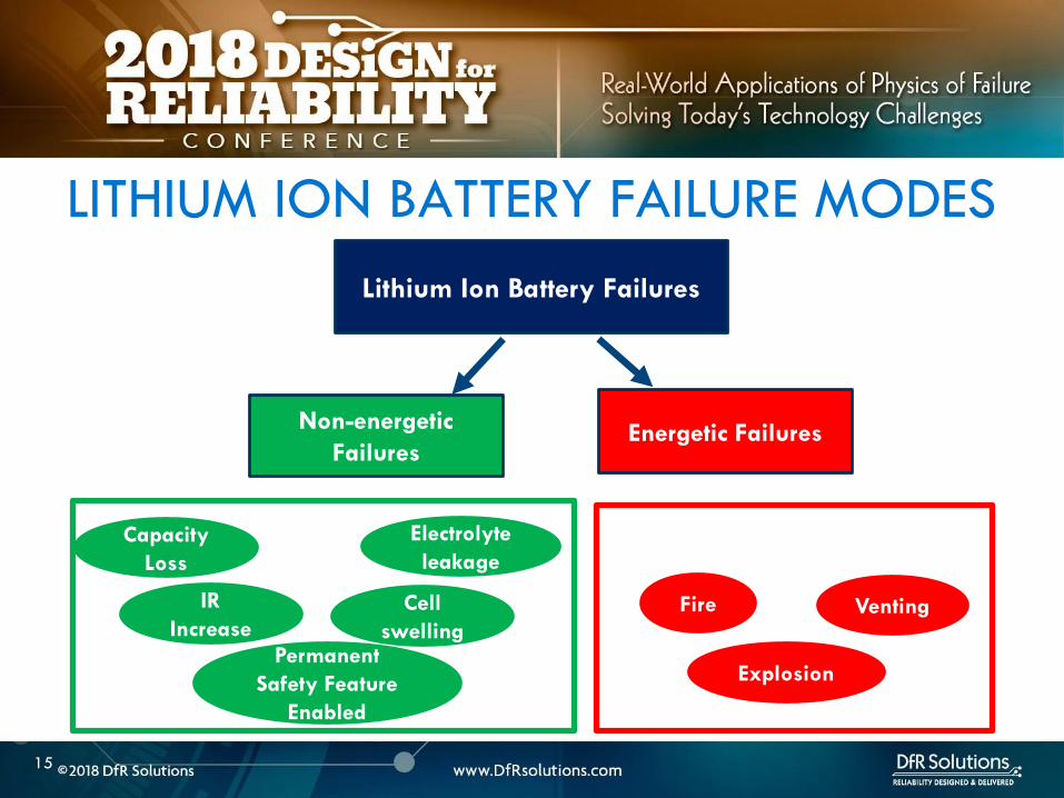
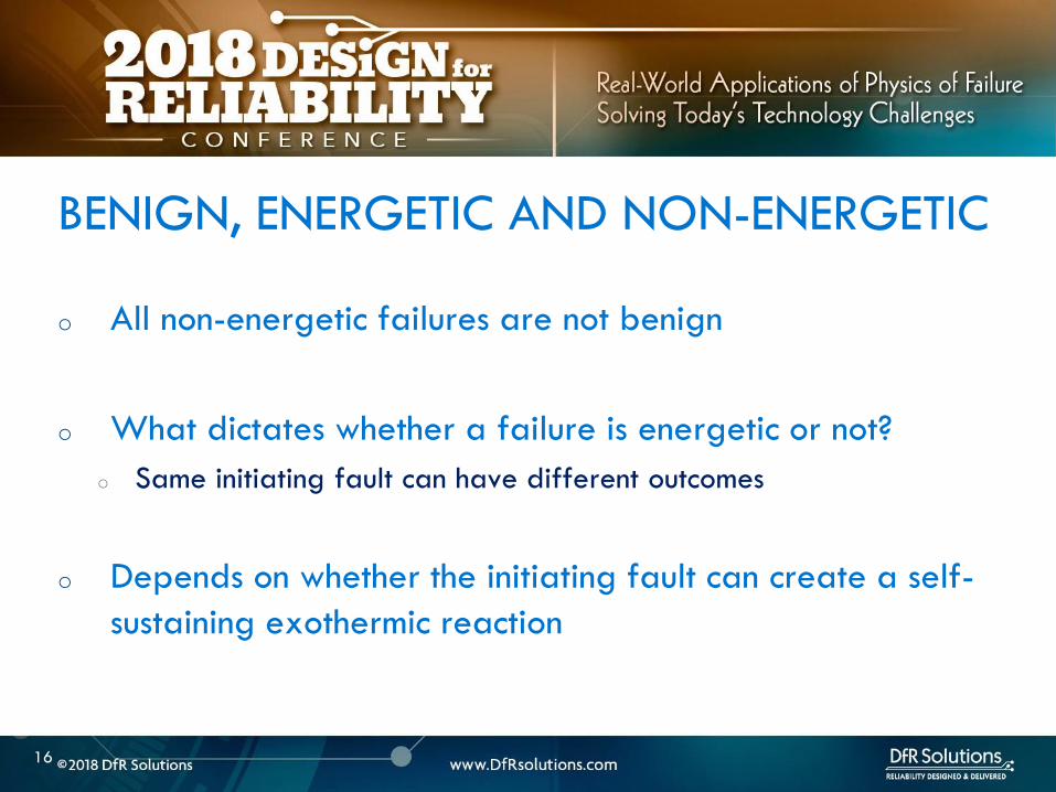
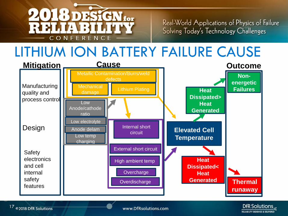
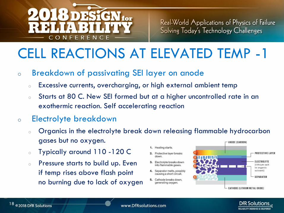
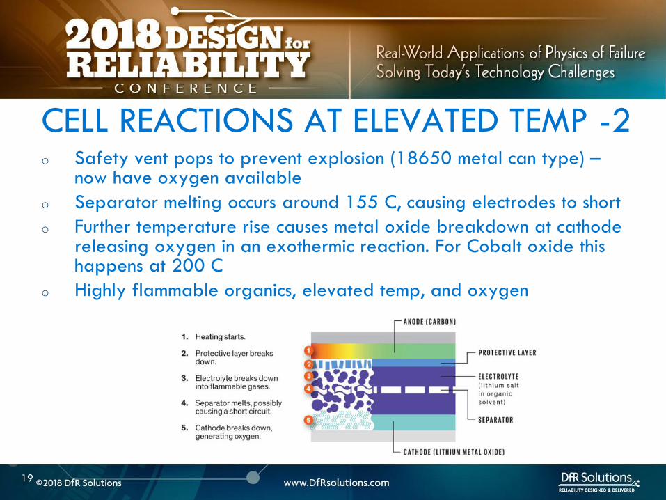
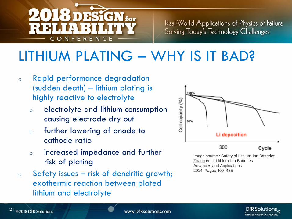
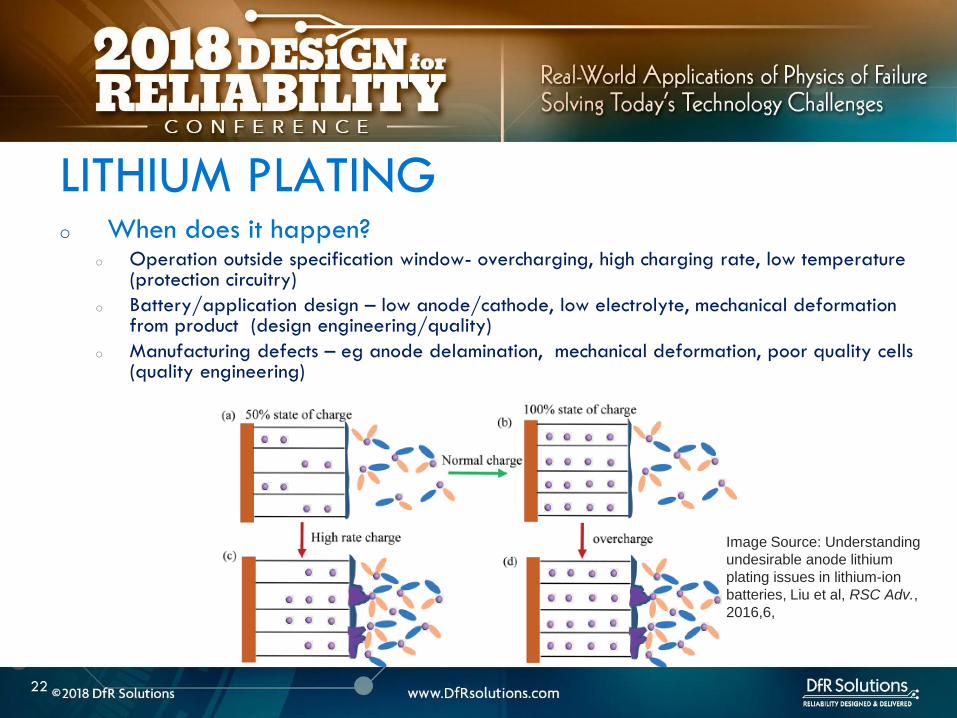
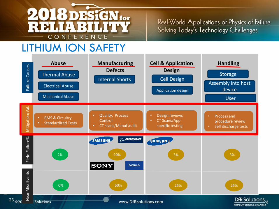
24
Internal Shorts ndash lsquoSoft underbellyrsquo
Internal shorts are typically the result of manufacturing defects
and are not effectively mitigated by safety systems
There is no good internal short circuit test that effectively
screens out these defects
The best defense is to have sound manufacturing process
controls
24
25
Improper BMS Design
o Poorly designed BMS and use of improper chargers are
responsible for some of the spectacular field failures
o Over-voltage failures are more spectacular and immediate than
grown in manufacturing defects which can take time to manifest
themselves
o Battery protection system includes the charger circuitry
protection circuit module located at the battery and is
optimized for a specific cell chemistry and application
o Good BMS design should include use of a custom connector so that
everyday USB chargers canrsquot be plugged in and allowed to abuse the
cell
26
LITHIUM ION CELL
MANUFACTURING PROCESS
26
27
o Incoming raw materials
o Electrode fabrication and cell assembly
o Environmental control
MANUFACTURING CONTROLS
28
o Energy density
o Pack as much active material as possible
o Minimize fines which make wetting difficult and require more
solvent and lower the solids content in slurry
o Power density
o Higher void volumes lower
electrode pressed density
and thickness
POWER DENSITY VS ENERGY DENSITY
29
o Incoming powders ndash Tap density particle size distribution
(PSD) surface area purity
o Binders and binder solvents
o Separator
o Electrolyte
o Current collectors
o Dry room storage (dew point of at least -40 C) Dew point is
used to express water vapor concentration at this level because
the corresponding relative humidity value is less than 1
MANUFACTURING INCOMING RAW MATERIALS
Separator
ELECTRODE FABRICATION
30
QC -Viscosity and
dispersion control
Riskndash shorts unreacted
lumps cause risk of
dryout and plating
QC ndashthickness slurry
metering
Riskndash non-uniform
coating leading to
shorting risk dryout
QC ndash thickness
adhesion
Riskndash blisters lack of
adhesion leading to
lithium plating
QC ndash electrode
thickness oncehr roller
gap check 4-6 hrs
porosity Riskndashlack of
cell performance for
energy or power
QC ndashburr control
tension control cutting
wheel maintenance
Riskndashinternal shorts
CELL ASSEMBLY FORMATION AND TESTING
Battery Manufacturing (nd) Retrieved March 22 2017 from httpw3siemenscommarketsglobalenbattery-
manufacturingapplicationsprocesspagesdefaultaspx
WindingStacking
QC ndashalignment
Riskndashinternal shorts
Tab welding
QC ndash burrweld height
control
Risk ndash internal shorts
QC ndash Weight before and
after stringent moisture
control
Risk ndash electrode dryout and
plating swelling from
moisture
QC ndash OCV IR weight
dimension check prior to
formation Rest to allow
electrolyte wetting after
filling followed by
formation
QC ndash OCV IR weight
dimension followed by
aging qualification tests
32
o The process involves a multi-zone oven with low temperatures for the first zone higher temperatures for the middle zone followed by a lower temperature for the final zone
o Specific temperatures will depend on binder chemistry and on slurry properties
o For PVDF binder on the cathode the recommended drying oven temperature profile for a 5-zone oven is as follows zone 1 ndash 75-90 degC zones 2-4 ndash 125-130 deg C zone 5 ndashapproximately 75 deg C A 4-zone oven should run at slower speed to allow more solvent evaporation
DRYING TEMPERATURES
33
o Incoming materials control
o Internal specifications that identify minimize and control all known
and likely impurities in incoming materials
o Internal specifications that control material properties or specs
o Ability to track changes in vendor materials
GENERAL MANUFACTURING GUIDELINES
34
o Manufacturing process control
o Safety critical equipment must be identified - process of verifying
equipment operation periodically Preventive maintenance plan
implementation
o Procedures to avoid metal contamination throughout the manufacturing
process
o Processes to collect loose material such as coating dust
o A method of detecting mechanical damage to electrodes in the
manufacturing process such as an automated vision system
o Statistical process control (SPC) to monitor maximum particle size slurry
viscosities coating weight calendered thickness weight of electrolyte
dispensed cell weight open circuit voltage (OCV) and capacity
GENERAL MANUFACTURING GUIDELINES
35
o Robust environmental control with a specific focus keeping ambient moisture minimized
o Destabilizes SEI layer and electrolyte and causes gassing
ENVIRONMENTAL CONTROL
36
LITHIUM ION CELL DESIGN
GUIDELINES
36
37
o Anode should overhang cathode by 05 mm or more on all sides for stacked cell or along top and bottom ends for jellyroll (min of 01 mm per IEEE 16251725)
o Anode should have higher electrochemical capacity than cathode by 10-15
o Example 1 g anode specific capacity is 350 mAhg So total anode capacity is 350 mAh
o 1 g cathode with specific capacity of 280 mAhg has total capacity of 280 mAh
Cathode shall never put out more lithium
ions than the anode can accommodate
CELL DESIGN GUIDELINES
Cathode
Separator
Anode
38
o Separator overhangs anode on all sides (room temperature to
at least 110 C- IEEE 16251725)
o Less than 5 shrinkage in both machine and transverse
directions at 90 C as a minimum
o Separator should have sufficient mechanical
strength to withstand cell assembly operations
CELL DESIGN GUIDELINES
Cathode
Separator
Anode
39
o Product design ndash make sure there is enough room for battery to
expand as it goes through charge ndashdischarge cycles Recommend 10
margin
o Pay particular attention to corners
o Poor manufacturing can reduce design margin
o Cutting operation variability
o Pick and place variability
CELL DESIGN GUIDELINES
40
ARTICLE QUALITY ASESSMENT
CELL CT SCANS AND
TEARDOWN
40
41
o Deep discharged cell
ARTICLE QUALITY ASESSMENT ndash CT SCANS
42
o Exercise - Describe what you see
o Electrode alignment is good on right image
o Variability in jellyroll winding on left and middle images
o Insufficient anode overlap in center of middle image
ARTICLE QUALITY ASESSMENT- CT SCANS
43
o Conduct CT scans and cell teardowns on a handful of units
o What to look for in CT scans
o Uniform cell winding or stacking
o No particulates
o No significant electrode delamination
o Anodes should overhang cathode by 05 mm ideally but a minimum
of 01 mm on each side
o No excessive deformation at pouch corners
o Cutting operationpick and place variability
PHYSICAL ARTICLE QUALITY ASESSMENT ndash CT SCANS
44
o Look at a few electrode pieces using optical microscopy
and SEMEDS
ARTICLE QUALITY ASESSMENT ndash TEARDOWNS
45
LITHIUM ION INTERNAL
AND EXTERNAL
PROTECTION SYSTEMS
45
o Positive Temperature Coefficient (PTC) device - inhibit high current surges
o Charge interrupt device (CID)- opens the electrical path if an excessively high charge voltage raises the internal cell pressure to a threshold value
o Safety vent- allows a controlled release of gas in the event of a rapid increase in cell pressure
o Hot electrolyte vapors and gas will always blow towards the burst disc instead of splitting the sides
o Shutdown Separators
CELL SAFETY PROTECTION MECHANISMS
46
o PTC - doughnut shaped device that sits between two metal
plates and is made of a polymeric material
o At high currents or temperatures resistance of the PTC increases
sharply causing the current to drop
PTC DEVICE
47
Image source nasagov
o The PTC is resettable and reverts
back after the fault is removed
o Once activated it subsequently
activates at a lower current and
temperature
o Works by releasing the connection at the positive terminal and
opening the electrical path
o Pressure valve which will disable the cell permanently of
pressure in the cell is too high
o Is not resettable
CHARGE INTERRUPT DEVICE
48
Image source nasagov
o Pouch cells do not have an internal CID PTC or safety vent
o Can have PTC or fuse elements in series with cell
POUCH CELL PROTECTION
49
Image source nasagov
50
o Separator is usually made of polyethylene (PE) polypropylene (PP) or a combination of the two
o Inner PE layer shuts down at 130degC by closing the pores the outer PP layers do not melt until reaching 155degC
SHUTDOWN SEPARATOR
Image Source Battery University
51
o Separator should increase its resistance by two orders of
magnitude at shutdown temperature (typically 130 C)
SHUTDOWN CURVES
Image Source Arora and Zhang Battery Separators Chem Rev 2004 104 (10) pp 4419ndash4462
52
o Know separator propertieso Thickness
o single vs multiple layer (PE PP or combination)
o ceramic coated or not
o Ceramic coatings can enhance thermal stability and prevent separator collapse till 200 C and beyond
o Ceramic coated separators usually may not have the mechanical strength to withstand winding and assembly- irrelevant for prismatic or stacked designs
SHUTDOWN SEPARATOR PROPERTIES
Impedance (1 kHz AC) vs Shutdown temperature of electrolyte soaked separators (ab) Polyethylene and (c)
polypropylene
53
BATTERY MANAGEMENT
SYSTEM (BMS) AND
PROTECTION CIRCUITRY
53
54
o Operating outside of specifications
Operating Outside Specifications
Image source Electropaedia
55
o Depends on a number of factors
o State of charge (SOC)
o Ambient temperature
o Cell chemistry
o Cell design
o Most severe thermal runaway occurs in an overcharged state
o Case temperatures can reach 600 C
o High temperatures are driven by exothermic reactions of the electrodes and the electrolyte
Severity of Thermal Runaway
56
o Self heating temperature o Fully charged 18650 cells brought to self heating temperature
(70 to 90 C) in adiabatic environment go into thermal runaway in 2 days
o Fully charged 18650 in adiabatic environment brought to 150 C (with separator melting) will run away in minutes
o UL standard requires fully charged cells to withstand 4 hour storage at 75 C and 10 min storage at 130 C
o IEEE standard requires 1 hour exposure at 130 C
o Overcharge o Charging a 42 V system to 5 V will almost certainly cause
immediate thermal runaway
Thermal Runaway Initiation ndash Some Numbers
57
o EV electric bus caught fire in Shenzhen China during
charging
o BMS Failure
o Without a BMS there is no
safe lithium ion battery
EV Bus Failure
58
o Consist of charger and a battery protection printed circuit board (PCB)
o Also called a battery protection circuit module (PCM)
o Important functions of protection systems include monitoring controlling and terminating charge and discharge as needed
o Failure of protection circuitry to either sense or respond to an out of range condition causes battery failure
ELECTRONIC PROTECTION SYSTEMS
59
o Maintain cells within operating window and prevent cells
from going into
o Over voltage
o Over current
o Over temperature
o Over discharge
o Balance individual cells to enhance overall capacity
o Disconnect batteries in a safe way in emergency situations
o Predict remaining capacity or state of charge
BMS FUNCTIONS
BMS Webinar httpswwwdfrsolutionscombattery-management-systems-and-safety-and-reliability-webinar
60
o Most obvious failure mode is exceeding specified voltage
o Charging a 42 V system to 5 V will almost certainly cause immediate thermal runaway
o Charging at excess currents
o Overcharge effects
o Anode ndash lithium plating rather than intercalation
o Cathode ndashexcess de-intercalation causes crystal structure to collapse and release heat
o Heat and gas release (both Joule heating and parasitic reactions)
o Electrolyte and electrode decomposition
OVER CHARGE - VOLTAGE
61
o Over voltage may be applied to the battery from a defective charger or due to improper monitoring on a single cell
o Slight overcharge (from minor deviations in voltage monitoring) causes capacity loss rather than direct thermal runaway
o Overvoltage protection can be implemented by opening a charge MOSFET or a fuse
o Overcharge protection is so critical that multiple independent circuits are typically used to prevent single points of failure
OVER VOLTAGE
62
o Hazard from over discharge is highly underestimated
o When a cell goes into deep discharge copper ions from the negative electrode current collector dissolve On recharge copper dendrites can form
o Over discharge can also cause breakdown of the SEI layer and gas formation
OVER DISCHARGE
Image Source Rui Guo1 Languang
Lu1 Minggao Ouyanga1 and Xuning
Feng1 Sci Rep 2016
63
How Does a Battery Go into
Deep Discharge
63
64
o Uncontrolled storage without appropriate recharge
procedures
o Mechanically damaged cells (from electronics impinging
on cell)
OVER DISCHARGE SCENARIOS
65
o Three kinds of discharge occur during storage o PCM sleep current and leakage currents
o Battery self discharge
o Manufacturing quality
o Temp
o State of charge
o Device sleep currents
o At 3 V (or other threshold cutoff) load is disconnected although above lsquoconsumption currentsrsquo are active
o At deep discharge cutoff value of 2 V (or other manufacturer specified value) PCM and device sleep currents are turned off but battery self discharge continues
Discharge During Storage
66
o Lithium ion self discharge around 1-2 per month + a
few cent for PCM
o High SOC and temperatures degrade storage life (and
cycle life)
o Rule of thumb ndash 10 C increase in temperature doubles self
discharge rate
o Store at conditions close to 25 C and 40 SOC
Battery Self Discharge
67
o To keep the contamination as low as possible to reduce
leakage current de-ionized water wash should be used
in the board cleaning process
o Verify the board cleanliness to make sure the levels of
contamination is low
o Investigate if humidity is an issue and that conformal
needs to be used
PCM (BMS) Self Discharge
68
o Have a pre-check charging function on batteries where deep discharge cutoff voltage was reached Charger circuit checks if a deeply discharged battery is reaches a threshold value in give time Otherwise considered a lsquodamagedrsquo battery
o Mitigating hazard from copper shunts
o Proper battery storage and recharge procedures
o Minimize PCM leakage currents
o Ensure cell quality
o Prevent cell mechanical damage
Deep Discharge Checklist
69
o Over current can causeo Degradation in cycle life
o Thermal runaway
o Threshold limits for current are functions of both current and time Protection circuit system can use different combinations of time and current to produce a fault Example - high currentshort time or lower currentlong time
o Some faults are recoverable such as when a MOSFET is turned on and others are non-recoverable such as when a fuse is ignited
o Causes of over-current could be a defective charger or due to an internal short
OVER CURRENT PROTECTIONS
70
o A good battery management system will limit charge current and voltage at high and low temperature extremes per Japan Electronics and Information Technology Industries Association (JEITA) guidelines
OVER CURRENT
(60 degC)
CoolCold Warm Hot
(0 degC)
Reduce charging
current andor
voltage
Reduce charging
current andor
voltage
71
o Current limits are incorporated into the protection
circuits located in pack or device
o Circuits monitor current in and out of battery and open up
MOSFET to interrupt current
o Backup protection usually includes a fuse or PTC placed
in series with battery pack
SHORT CIRCUIT PROTECTION
72
BATTERY LIFE DEGRADATION
AND STORAGE
72
73
o Battery life example
o Nominal capacity is 2900 mAh End of life capacity at 80 of initial capacity is 2300 mAh
o Is this data sufficient to give you a life of 500 cycles
BATTERY LIFE AND AGING ISSUES
74
o Calendar aging vs cycle life agingo Insertion or ejection of the Lithium ions into and out of the intercalation
spaces during cycling causes the electrode materials to swell or contract
o Repetitive cycling can weaken the electrode structure reducing its adhesion to the current collector This can lead to reduction in charge capacity
BATTERY LIFE DEGRADATION
75
o Storage degradation high temperature aging causes
growth of the passivating layer
o It consumes lithium and electrolyte and leads to capacity loss
and impedance increase (both capacity and power fade)
Pores can be blocked as a result
o Low rate batteries may not see a big impact
(voltage drop = IR)
BATTERY LIFE DEGRADATION CALENDAR AGING
76
o Have two distinct mechanisms
that impact cell life
o Battery aging tests should
involve high temperature
storage tests
BATTERY LIFE DEGRADATION CALENDAR AGING
Image source Electropaedia
77
o Characterize both reversible and irreversible storage loss
o In this example 25 irreversible and 5 reversible
capacity loss
REVERSIBLE VS IRREVERSIBLE STORAGE LOSS
Assume a = 2900 mAh
d = 70 a = 2030 mAh
e = 95 a = 2700 mAh
a
d
e
78
LITHIUM ION CHEMISTRIES
78
79
o Term Lithium-Ion encompasses many different chemistries
o Anode ndash graphite (Lithium Titanate LTO for very fast charge cells)
o Cathode - Cathodes are lithiated metal oxides or lithiated metal
phosphates
o Lithium Cobalt Oxide (LCO)
o Lithium Iron Phosphate(LFP)
o Nickel Manganese Cobalt (NMC)
o Lithium Manganese Oxide(LMO)
o Cathode chemistry is where you get enhancements in safety
energy and power density
Battery Chemistry
80
o Lithium Cobalt Oxide (LCO) ndash commonly used in consumer electronics
o High energy density
o Low power
o Least safe
o Moderate cycle life
Battery Chemistry
o Lithium Iron Phosphate(LFP) ndashndash automotive power tools UPS e-cigs
o Safest chemistry
o High power density
o Very high cycle life
o Lower voltageLower energy density
o Higher self discharge rate
81
o Nickel Manganese Cobalt (NMC) ndashcommon in tools EV applications
e-cigs ndash usually 13 proportion but customization is possible
o Can be optimized for power or energy
o Good safety
o Good cycle life
Battery Chemistry
o Lithium Manganese Oxide(LiMn2O4) ndashndash power tools EV and hybrid vehicles e-cigs
o Low internal resistancehigh power capability (from Manganese)
o Good safety
o Lower energy ndash blends with NMC are used to enhance energy
82
Battery Chemistry Summary
Chemistry LCO NMC LFP LMO
Nominal Voltage(V) 36-37 36-37 32-32 36-37
Charge Voltage(V) 42 42 35-36 42
Safety Poor Good Highest Good
Cycle Life gt500 gt500 gt1000 gt500
Peak Load current (Best result) 2C
(lt1C)
gt30C
(lt10 C)
gt30C
(lt10 C)
Specific energy (WhKg) 150-250 90-120 100-150
Thermal Runaway Temp (ordmC) 150 210 gt270
Used Since 1991 2003 1999 1996
Designation ICR INR IFR IMR
o Knowing chemistry helps to map out worst case scenario
o For pouch cells look at MSDS
83
o Do not see the word LCO
Battery Chemistry in Current EV Systems
84
ESTIMATING STORED ENERGY
84
85
o Risk assessment
o How much energy and wattage does the battery have
o How fast is the energy released
o Is the product worn on or close to the body
o What is the chemistry
o New product category Are there specific user behaviorsproduct
design interactions that increase the risk and impact of thermal away
o Risk mitigation
o Trust but verify
o Do not trust till you verify
o Map out the worst case
BATTERY RISK ASESSMENT
86
o Stored energy is a combination of electrical and chemical
energy
o Electrical Energy
o Chemical energy may be approximated by using heats of
combustion of various flammable components in cell
STORED ENERGY
87
o Specification
o 37 V
o 296 Wh
o 800 mAh
o Useful information 1 Wh = 36 kJ
o Total stored energy = 296 36 = 1065 kJ
STORED ENERGY PRISMATIC EXAMPLE
88
o Assume 1 to 5 g of electrolyte for small prismatic or pouch cell Assume 05 to 1 g of separator
o Electrolyte solvents are generally organic carbonates such as diethyl carbonate (DEC) ethylene carbonate dimethyl carbonate and ethylmethyl carbonate
o Using the heat of combustion of DEC at 2092 kJg 21 to 105 kJ of energy from electrolyte combustion
o Separator is made of polyethylene polypropylene or combination of the two
o By using polypropylene heat of combustion as an approximation at 4266 kJg 21 to 42 kJ energy for the separator
o Total chemical energy approximation is 42 to 147 kJ
STORED CHEMICAL ENERGY SMALL PRISMATIC
89
o Estimate of total energy released is 52 to 117 kJ
STORED ENERGY SMALL PRISMATIC
Cell Type Energy Low (kJ) High (kJ) Amount (g)
Chemical Energy Combustible
materials Total
42 147
Separator 21 42 05 to 1
Electrolyte 21 105 1 to 5
Electrical (nominal voltage to fully
charged state)
1065 121
Prismatic Total 5265 117
90
o Specification o 37 V
o 962 Wh
o 2600 mAh
o Useful information 1 Wh = 36 kJo Heat of combustion of DEC = 2092 kJg
o Polypropylene heat of combustion = 4266 kJg
o For comparison a 190 g stick of dynamite can release 1 MJ of energy1
STORED ENERGY 18650 EXAMPLE SOLUTION
Cell Type Energy Low (kJ) High (kJ) Amount (g)
Chemical Energy Combustible materials Total 122 23561
Separator 5972 6825 14 to 16
Electrolyte 6236 16736 3 to 8
Electrical (nominal voltage to fully charged
state)
3462 393
18650 Total 157 207
1 httpsenwikipediaorgwikiDynamite
91
Is the 18650 Hazard
Relevant to You
91
92
o Smaller batteries - 20 mAh to 500 mAh
o Energy released is 10- to 100 times lower than the 18650o Smaller capacity batteries release smaller amounts of energy
o 150 -200 mAh batteries generally used for headphone applications such as in illustration
Small Batteries
93
o Calculate total energy released from your cell
o Electrical energy + chemical energy
o Use thermal analysis to estimate temperature rise and
compare against allowable surface temperaturesstandards
Worst Case Analysis
Material Burn Threshold for
contact of 05 s (ordmC)
Bare metal 67-73
Ceramics glass and stone 84-90
Plastics 91-99
Wood 128-155
European standard BS EN 132022000
94
o Potential for burn hazard may be estimated
Skin Burn Temperatures
Effect Description Skin
Temperature
(ordmC)
Pain Tingling hot sensation 44
1st degree burn Superficial injury to outer layer skin
is reddened painful
44-55
2nd degree burn Outer layer is burned through
second layer damaged skin is moist
and reddened with blisters intense
pain
55-60
3rd degree burn All skin layers are damaged 60
95
VENT GAS RISK
95
96
o Vent gases mainly consist of H2 hydrocarbons (also called THC or
total hydrocarbon concentration in figure below) CO2 and CO
o Flammable gases include H2 CO and hydrocarbons
Vent Gas Flammability
Ref 1 US DOTFAA Study Lithium Battery Thermal Runaway Vent Gas Analysis Nov 2016
Major gas species concentration for18650 LiCoO2 cell
97
o When a lithium ion battery vents the gas mixture will mix with surrounding air and may or may not ignite
o The following conditions have to be met for an ignition evento Air fuel mixture is within the Lower Flammability Limit (LFL) and (Upper
Flammability Limit) UFL limits
o Ignition source is present
o The most dangerous materials are those with the lowest flash point and widest flammable ranges
o A hot cell case or hot metal sparks ejected from the cell could create an ignition event if the mixture is within flammability limits
Ignition Risk
98
CHEMICAL SPILL RISK
98
99
o In the absence of a fire potential hazard from a damaged lithium ion battery includes the following
o Release of a electrolyte containing a corrosive salt Electrolyte is extremely corrosive and may cause permanent blindness If ingested through the mouth liver and kidney damage is possible
o Reaction of the electrolyte with waterhumidity may generate hydrofluoric acid which are highly toxic and corrosive to the eyes nose throat and skin
o Release of volatile organics toxic gases such as CO HF
Chemical Spill Risk
Ref Various MSDS sheets
100
o Lithiated carbon in a charged anode the Solid Electrolyte
Interphase (SEI) layer or any free lithium (dendritesplating)
will burst into flames when exposed to moist air
o Reaction of lithium with water produces H2 in an exothermic
reaction
o Significant heat is released in this reaction and this can ignite the H2
Chemical Risk ndash Lithium Ion and Primary Lithium
101
Lithium Ion Life Cycle ndash
Cradle to Grave
101
102
o Cell Manufacturing
o brought to a low to moderate state of charge for shippingstorage
o Transportation
o Warehouse storage
o Pack or device assembly
o OEM device shipment
o Device Usage
o Recycling
LITHIUM ION BATTERY LIFE CYCLE
103
o Almost all failures are related to improper packaging (potential for mechanical damage and external shorts) and shipment procedures
o International Air Transportation Association (IATA) shipment procedures for dangerous goods Cell manufacturers must show proof of UN 383 certification
o 1) Lithium ion batteries (not contained in equipment) shall not be shipped with SOC greater than 30
o 2) Shall pass UN 383 battery of tests
o 3) Shall not be shipped on passenger aircraft
Transportation Procedures
See httpwwwiataorgwhatwedocargodgrDocumentslithium-battery-shipping-guidelinespdf
104
o Small cell shipment exceptions to class 9 dangerous goods classification
o Only Carry-on and Section II are exempt from Class 9 hazardous material
designation
Transportation Procedures
Image source
Battery university
105
o Have procedures in place for safe handling of lithium ion
batteries
o Protection from short circuit high temperature is critical
o Pouch cells must use recessed packaging trays
Storage and Warehouse Handling
106
o Do not single stream recycle lithium ion batteries
o High risk of ignition with surrounding paper and cardboard
o Lithium Ion batteries can be recycled but only at specified
locations Visit httpswwwcall2recycleorglocator
(Rechargeable Battery Recycling Corporation)
o 86 of US and Canadian residents live within 10 miles of
drop-off location
o httpswwwcall2recycleorg for battery recycling resources
Lithium Ion Recycling Procedures
107
o Do not discard as trash
o When collecting batteries make sure they are taped or
insulated
o Recommend drop-off instead
Lithium Ion Recycling Procedures
108
COMPLIANCE TESTING
108
109
o Tests that have the same name under different standards are not always the same
o There are differences in terms of the state of charge aging of the cells and sample sizes and these can have significant differences
o The vendor must state the test standard specify a test description in addition to the name of the test
BATTERY COMPLIANCE TESTING
110
o UNDOT 383 Covers transportation safety testing for all lithium
metal and lithium ion cells and batteries This is mandatory
o UL safety standards
o UL 1642 ndash This standard is used for testing lithium cells Battery level tests
are covered by UL 2054
o UL 2054 (Household and Commercial Batteries) ndash For lithium batteries UL
2054 defers all component cell level testing to UL 1642
o CEIIEC 62133 ndash this standard is voluntary in the US but some
countries specify this standard
BATTERY COMPLIANCE TESTING
111
o IEEE 16251725 ndash These standards are applicable to rechargeable batteries for Multi-cell mobile computing devices and for Cellular phones respectively (CTIA or Wireless Association)
o These standards take the most comprehensive approach to battery testing and emphasize that battery pack safety is a function of a) the individual cells b) the battery pack c) the host device d) power supply accessories e) the user f) the environment
o Both standards require design analysis tools such as FMEA or fault tree analysis They also encompass industry best practices in manufacturing and in the areas of cell pack system and charging accessory design
BATTERY COMPLIANCE TESTING
112
The more you know the better
Parting Thought
Questions
bull Contact Vidyu Challa
vchalladfrsolutionscom
301-640-5834
bull wwwdfrsolutionscom resources page for
battery and other electronic reliability
resources
114
APPENDIX
114
115
Battery Seal Quality
o Moisture ingress through
o Laminate face (extremely low due to metal barrier)
o Interfaces (no metal barrier)
o Terminals (good sealing practices mandatory)
o Compensate through large seal width ( generally 2 mm
min)
o Seal width checks
116
o Flash points for common components of lithium ion battery
electrolytes are below
FLASH POINTS
Ref CRC handbook of chemistry and physics
Electrolyte Component Boiling Point Flash Point
Propylene carbonate (PC) 242degC 135degC
468degF 275degF
Ethylene carbonate (EC) 248degC 145degC
478degF 293degF
Di-Methyl carbonate (DMC) 91degC 18degC
195degF 64degF
Diethyl carbonate (DEC) 126degC 25degC
259degF 77degF
Ethyl methyl carbonate (EMC) 107degC 25degC
225degF 77degF
117
o Flammability limits for vent gases from Li Ion batteries are in
table below
Ref Combustion Flames and Explosion of Gases 2nd Edition Academic Press NY 1961
Compound Lower flammability limit
(fuel volume )
Upper flammability limit
(fuel volume )
Hydrogen 40 750
Carbon monoxide 125 740
Methane 53 150
Ethylene 31 320
Ethane 30 125
Propylene 24 103
C4 hydrocarbons ~ 16-19 ~ 84 ndash 97
C5 hydrocarbons ~ 14-15 ~ 75 ndash 87
26
LITHIUM ION CELL
MANUFACTURING PROCESS
26
27
o Incoming raw materials
o Electrode fabrication and cell assembly
o Environmental control
MANUFACTURING CONTROLS
28
o Energy density
o Pack as much active material as possible
o Minimize fines which make wetting difficult and require more
solvent and lower the solids content in slurry
o Power density
o Higher void volumes lower
electrode pressed density
and thickness
POWER DENSITY VS ENERGY DENSITY
29
o Incoming powders ndash Tap density particle size distribution
(PSD) surface area purity
o Binders and binder solvents
o Separator
o Electrolyte
o Current collectors
o Dry room storage (dew point of at least -40 C) Dew point is
used to express water vapor concentration at this level because
the corresponding relative humidity value is less than 1
MANUFACTURING INCOMING RAW MATERIALS
Separator
ELECTRODE FABRICATION
30
QC -Viscosity and
dispersion control
Riskndash shorts unreacted
lumps cause risk of
dryout and plating
QC ndashthickness slurry
metering
Riskndash non-uniform
coating leading to
shorting risk dryout
QC ndash thickness
adhesion
Riskndash blisters lack of
adhesion leading to
lithium plating
QC ndash electrode
thickness oncehr roller
gap check 4-6 hrs
porosity Riskndashlack of
cell performance for
energy or power
QC ndashburr control
tension control cutting
wheel maintenance
Riskndashinternal shorts
CELL ASSEMBLY FORMATION AND TESTING
Battery Manufacturing (nd) Retrieved March 22 2017 from httpw3siemenscommarketsglobalenbattery-
manufacturingapplicationsprocesspagesdefaultaspx
WindingStacking
QC ndashalignment
Riskndashinternal shorts
Tab welding
QC ndash burrweld height
control
Risk ndash internal shorts
QC ndash Weight before and
after stringent moisture
control
Risk ndash electrode dryout and
plating swelling from
moisture
QC ndash OCV IR weight
dimension check prior to
formation Rest to allow
electrolyte wetting after
filling followed by
formation
QC ndash OCV IR weight
dimension followed by
aging qualification tests
32
o The process involves a multi-zone oven with low temperatures for the first zone higher temperatures for the middle zone followed by a lower temperature for the final zone
o Specific temperatures will depend on binder chemistry and on slurry properties
o For PVDF binder on the cathode the recommended drying oven temperature profile for a 5-zone oven is as follows zone 1 ndash 75-90 degC zones 2-4 ndash 125-130 deg C zone 5 ndashapproximately 75 deg C A 4-zone oven should run at slower speed to allow more solvent evaporation
DRYING TEMPERATURES
33
o Incoming materials control
o Internal specifications that identify minimize and control all known
and likely impurities in incoming materials
o Internal specifications that control material properties or specs
o Ability to track changes in vendor materials
GENERAL MANUFACTURING GUIDELINES
34
o Manufacturing process control
o Safety critical equipment must be identified - process of verifying
equipment operation periodically Preventive maintenance plan
implementation
o Procedures to avoid metal contamination throughout the manufacturing
process
o Processes to collect loose material such as coating dust
o A method of detecting mechanical damage to electrodes in the
manufacturing process such as an automated vision system
o Statistical process control (SPC) to monitor maximum particle size slurry
viscosities coating weight calendered thickness weight of electrolyte
dispensed cell weight open circuit voltage (OCV) and capacity
GENERAL MANUFACTURING GUIDELINES
35
o Robust environmental control with a specific focus keeping ambient moisture minimized
o Destabilizes SEI layer and electrolyte and causes gassing
ENVIRONMENTAL CONTROL
36
LITHIUM ION CELL DESIGN
GUIDELINES
36
37
o Anode should overhang cathode by 05 mm or more on all sides for stacked cell or along top and bottom ends for jellyroll (min of 01 mm per IEEE 16251725)
o Anode should have higher electrochemical capacity than cathode by 10-15
o Example 1 g anode specific capacity is 350 mAhg So total anode capacity is 350 mAh
o 1 g cathode with specific capacity of 280 mAhg has total capacity of 280 mAh
Cathode shall never put out more lithium
ions than the anode can accommodate
CELL DESIGN GUIDELINES
Cathode
Separator
Anode
38
o Separator overhangs anode on all sides (room temperature to
at least 110 C- IEEE 16251725)
o Less than 5 shrinkage in both machine and transverse
directions at 90 C as a minimum
o Separator should have sufficient mechanical
strength to withstand cell assembly operations
CELL DESIGN GUIDELINES
Cathode
Separator
Anode
39
o Product design ndash make sure there is enough room for battery to
expand as it goes through charge ndashdischarge cycles Recommend 10
margin
o Pay particular attention to corners
o Poor manufacturing can reduce design margin
o Cutting operation variability
o Pick and place variability
CELL DESIGN GUIDELINES
40
ARTICLE QUALITY ASESSMENT
CELL CT SCANS AND
TEARDOWN
40
41
o Deep discharged cell
ARTICLE QUALITY ASESSMENT ndash CT SCANS
42
o Exercise - Describe what you see
o Electrode alignment is good on right image
o Variability in jellyroll winding on left and middle images
o Insufficient anode overlap in center of middle image
ARTICLE QUALITY ASESSMENT- CT SCANS
43
o Conduct CT scans and cell teardowns on a handful of units
o What to look for in CT scans
o Uniform cell winding or stacking
o No particulates
o No significant electrode delamination
o Anodes should overhang cathode by 05 mm ideally but a minimum
of 01 mm on each side
o No excessive deformation at pouch corners
o Cutting operationpick and place variability
PHYSICAL ARTICLE QUALITY ASESSMENT ndash CT SCANS
44
o Look at a few electrode pieces using optical microscopy
and SEMEDS
ARTICLE QUALITY ASESSMENT ndash TEARDOWNS
45
LITHIUM ION INTERNAL
AND EXTERNAL
PROTECTION SYSTEMS
45
o Positive Temperature Coefficient (PTC) device - inhibit high current surges
o Charge interrupt device (CID)- opens the electrical path if an excessively high charge voltage raises the internal cell pressure to a threshold value
o Safety vent- allows a controlled release of gas in the event of a rapid increase in cell pressure
o Hot electrolyte vapors and gas will always blow towards the burst disc instead of splitting the sides
o Shutdown Separators
CELL SAFETY PROTECTION MECHANISMS
46
o PTC - doughnut shaped device that sits between two metal
plates and is made of a polymeric material
o At high currents or temperatures resistance of the PTC increases
sharply causing the current to drop
PTC DEVICE
47
Image source nasagov
o The PTC is resettable and reverts
back after the fault is removed
o Once activated it subsequently
activates at a lower current and
temperature
o Works by releasing the connection at the positive terminal and
opening the electrical path
o Pressure valve which will disable the cell permanently of
pressure in the cell is too high
o Is not resettable
CHARGE INTERRUPT DEVICE
48
Image source nasagov
o Pouch cells do not have an internal CID PTC or safety vent
o Can have PTC or fuse elements in series with cell
POUCH CELL PROTECTION
49
Image source nasagov
50
o Separator is usually made of polyethylene (PE) polypropylene (PP) or a combination of the two
o Inner PE layer shuts down at 130degC by closing the pores the outer PP layers do not melt until reaching 155degC
SHUTDOWN SEPARATOR
Image Source Battery University
51
o Separator should increase its resistance by two orders of
magnitude at shutdown temperature (typically 130 C)
SHUTDOWN CURVES
Image Source Arora and Zhang Battery Separators Chem Rev 2004 104 (10) pp 4419ndash4462
52
o Know separator propertieso Thickness
o single vs multiple layer (PE PP or combination)
o ceramic coated or not
o Ceramic coatings can enhance thermal stability and prevent separator collapse till 200 C and beyond
o Ceramic coated separators usually may not have the mechanical strength to withstand winding and assembly- irrelevant for prismatic or stacked designs
SHUTDOWN SEPARATOR PROPERTIES
Impedance (1 kHz AC) vs Shutdown temperature of electrolyte soaked separators (ab) Polyethylene and (c)
polypropylene
53
BATTERY MANAGEMENT
SYSTEM (BMS) AND
PROTECTION CIRCUITRY
53
54
o Operating outside of specifications
Operating Outside Specifications
Image source Electropaedia
55
o Depends on a number of factors
o State of charge (SOC)
o Ambient temperature
o Cell chemistry
o Cell design
o Most severe thermal runaway occurs in an overcharged state
o Case temperatures can reach 600 C
o High temperatures are driven by exothermic reactions of the electrodes and the electrolyte
Severity of Thermal Runaway
56
o Self heating temperature o Fully charged 18650 cells brought to self heating temperature
(70 to 90 C) in adiabatic environment go into thermal runaway in 2 days
o Fully charged 18650 in adiabatic environment brought to 150 C (with separator melting) will run away in minutes
o UL standard requires fully charged cells to withstand 4 hour storage at 75 C and 10 min storage at 130 C
o IEEE standard requires 1 hour exposure at 130 C
o Overcharge o Charging a 42 V system to 5 V will almost certainly cause
immediate thermal runaway
Thermal Runaway Initiation ndash Some Numbers
57
o EV electric bus caught fire in Shenzhen China during
charging
o BMS Failure
o Without a BMS there is no
safe lithium ion battery
EV Bus Failure
58
o Consist of charger and a battery protection printed circuit board (PCB)
o Also called a battery protection circuit module (PCM)
o Important functions of protection systems include monitoring controlling and terminating charge and discharge as needed
o Failure of protection circuitry to either sense or respond to an out of range condition causes battery failure
ELECTRONIC PROTECTION SYSTEMS
59
o Maintain cells within operating window and prevent cells
from going into
o Over voltage
o Over current
o Over temperature
o Over discharge
o Balance individual cells to enhance overall capacity
o Disconnect batteries in a safe way in emergency situations
o Predict remaining capacity or state of charge
BMS FUNCTIONS
BMS Webinar httpswwwdfrsolutionscombattery-management-systems-and-safety-and-reliability-webinar
60
o Most obvious failure mode is exceeding specified voltage
o Charging a 42 V system to 5 V will almost certainly cause immediate thermal runaway
o Charging at excess currents
o Overcharge effects
o Anode ndash lithium plating rather than intercalation
o Cathode ndashexcess de-intercalation causes crystal structure to collapse and release heat
o Heat and gas release (both Joule heating and parasitic reactions)
o Electrolyte and electrode decomposition
OVER CHARGE - VOLTAGE
61
o Over voltage may be applied to the battery from a defective charger or due to improper monitoring on a single cell
o Slight overcharge (from minor deviations in voltage monitoring) causes capacity loss rather than direct thermal runaway
o Overvoltage protection can be implemented by opening a charge MOSFET or a fuse
o Overcharge protection is so critical that multiple independent circuits are typically used to prevent single points of failure
OVER VOLTAGE
62
o Hazard from over discharge is highly underestimated
o When a cell goes into deep discharge copper ions from the negative electrode current collector dissolve On recharge copper dendrites can form
o Over discharge can also cause breakdown of the SEI layer and gas formation
OVER DISCHARGE
Image Source Rui Guo1 Languang
Lu1 Minggao Ouyanga1 and Xuning
Feng1 Sci Rep 2016
63
How Does a Battery Go into
Deep Discharge
63
64
o Uncontrolled storage without appropriate recharge
procedures
o Mechanically damaged cells (from electronics impinging
on cell)
OVER DISCHARGE SCENARIOS
65
o Three kinds of discharge occur during storage o PCM sleep current and leakage currents
o Battery self discharge
o Manufacturing quality
o Temp
o State of charge
o Device sleep currents
o At 3 V (or other threshold cutoff) load is disconnected although above lsquoconsumption currentsrsquo are active
o At deep discharge cutoff value of 2 V (or other manufacturer specified value) PCM and device sleep currents are turned off but battery self discharge continues
Discharge During Storage
66
o Lithium ion self discharge around 1-2 per month + a
few cent for PCM
o High SOC and temperatures degrade storage life (and
cycle life)
o Rule of thumb ndash 10 C increase in temperature doubles self
discharge rate
o Store at conditions close to 25 C and 40 SOC
Battery Self Discharge
67
o To keep the contamination as low as possible to reduce
leakage current de-ionized water wash should be used
in the board cleaning process
o Verify the board cleanliness to make sure the levels of
contamination is low
o Investigate if humidity is an issue and that conformal
needs to be used
PCM (BMS) Self Discharge
68
o Have a pre-check charging function on batteries where deep discharge cutoff voltage was reached Charger circuit checks if a deeply discharged battery is reaches a threshold value in give time Otherwise considered a lsquodamagedrsquo battery
o Mitigating hazard from copper shunts
o Proper battery storage and recharge procedures
o Minimize PCM leakage currents
o Ensure cell quality
o Prevent cell mechanical damage
Deep Discharge Checklist
69
o Over current can causeo Degradation in cycle life
o Thermal runaway
o Threshold limits for current are functions of both current and time Protection circuit system can use different combinations of time and current to produce a fault Example - high currentshort time or lower currentlong time
o Some faults are recoverable such as when a MOSFET is turned on and others are non-recoverable such as when a fuse is ignited
o Causes of over-current could be a defective charger or due to an internal short
OVER CURRENT PROTECTIONS
70
o A good battery management system will limit charge current and voltage at high and low temperature extremes per Japan Electronics and Information Technology Industries Association (JEITA) guidelines
OVER CURRENT
(60 degC)
CoolCold Warm Hot
(0 degC)
Reduce charging
current andor
voltage
Reduce charging
current andor
voltage
71
o Current limits are incorporated into the protection
circuits located in pack or device
o Circuits monitor current in and out of battery and open up
MOSFET to interrupt current
o Backup protection usually includes a fuse or PTC placed
in series with battery pack
SHORT CIRCUIT PROTECTION
72
BATTERY LIFE DEGRADATION
AND STORAGE
72
73
o Battery life example
o Nominal capacity is 2900 mAh End of life capacity at 80 of initial capacity is 2300 mAh
o Is this data sufficient to give you a life of 500 cycles
BATTERY LIFE AND AGING ISSUES
74
o Calendar aging vs cycle life agingo Insertion or ejection of the Lithium ions into and out of the intercalation
spaces during cycling causes the electrode materials to swell or contract
o Repetitive cycling can weaken the electrode structure reducing its adhesion to the current collector This can lead to reduction in charge capacity
BATTERY LIFE DEGRADATION
75
o Storage degradation high temperature aging causes
growth of the passivating layer
o It consumes lithium and electrolyte and leads to capacity loss
and impedance increase (both capacity and power fade)
Pores can be blocked as a result
o Low rate batteries may not see a big impact
(voltage drop = IR)
BATTERY LIFE DEGRADATION CALENDAR AGING
76
o Have two distinct mechanisms
that impact cell life
o Battery aging tests should
involve high temperature
storage tests
BATTERY LIFE DEGRADATION CALENDAR AGING
Image source Electropaedia
77
o Characterize both reversible and irreversible storage loss
o In this example 25 irreversible and 5 reversible
capacity loss
REVERSIBLE VS IRREVERSIBLE STORAGE LOSS
Assume a = 2900 mAh
d = 70 a = 2030 mAh
e = 95 a = 2700 mAh
a
d
e
78
LITHIUM ION CHEMISTRIES
78
79
o Term Lithium-Ion encompasses many different chemistries
o Anode ndash graphite (Lithium Titanate LTO for very fast charge cells)
o Cathode - Cathodes are lithiated metal oxides or lithiated metal
phosphates
o Lithium Cobalt Oxide (LCO)
o Lithium Iron Phosphate(LFP)
o Nickel Manganese Cobalt (NMC)
o Lithium Manganese Oxide(LMO)
o Cathode chemistry is where you get enhancements in safety
energy and power density
Battery Chemistry
80
o Lithium Cobalt Oxide (LCO) ndash commonly used in consumer electronics
o High energy density
o Low power
o Least safe
o Moderate cycle life
Battery Chemistry
o Lithium Iron Phosphate(LFP) ndashndash automotive power tools UPS e-cigs
o Safest chemistry
o High power density
o Very high cycle life
o Lower voltageLower energy density
o Higher self discharge rate
81
o Nickel Manganese Cobalt (NMC) ndashcommon in tools EV applications
e-cigs ndash usually 13 proportion but customization is possible
o Can be optimized for power or energy
o Good safety
o Good cycle life
Battery Chemistry
o Lithium Manganese Oxide(LiMn2O4) ndashndash power tools EV and hybrid vehicles e-cigs
o Low internal resistancehigh power capability (from Manganese)
o Good safety
o Lower energy ndash blends with NMC are used to enhance energy
82
Battery Chemistry Summary
Chemistry LCO NMC LFP LMO
Nominal Voltage(V) 36-37 36-37 32-32 36-37
Charge Voltage(V) 42 42 35-36 42
Safety Poor Good Highest Good
Cycle Life gt500 gt500 gt1000 gt500
Peak Load current (Best result) 2C
(lt1C)
gt30C
(lt10 C)
gt30C
(lt10 C)
Specific energy (WhKg) 150-250 90-120 100-150
Thermal Runaway Temp (ordmC) 150 210 gt270
Used Since 1991 2003 1999 1996
Designation ICR INR IFR IMR
o Knowing chemistry helps to map out worst case scenario
o For pouch cells look at MSDS
83
o Do not see the word LCO
Battery Chemistry in Current EV Systems
84
ESTIMATING STORED ENERGY
84
85
o Risk assessment
o How much energy and wattage does the battery have
o How fast is the energy released
o Is the product worn on or close to the body
o What is the chemistry
o New product category Are there specific user behaviorsproduct
design interactions that increase the risk and impact of thermal away
o Risk mitigation
o Trust but verify
o Do not trust till you verify
o Map out the worst case
BATTERY RISK ASESSMENT
86
o Stored energy is a combination of electrical and chemical
energy
o Electrical Energy
o Chemical energy may be approximated by using heats of
combustion of various flammable components in cell
STORED ENERGY
87
o Specification
o 37 V
o 296 Wh
o 800 mAh
o Useful information 1 Wh = 36 kJ
o Total stored energy = 296 36 = 1065 kJ
STORED ENERGY PRISMATIC EXAMPLE
88
o Assume 1 to 5 g of electrolyte for small prismatic or pouch cell Assume 05 to 1 g of separator
o Electrolyte solvents are generally organic carbonates such as diethyl carbonate (DEC) ethylene carbonate dimethyl carbonate and ethylmethyl carbonate
o Using the heat of combustion of DEC at 2092 kJg 21 to 105 kJ of energy from electrolyte combustion
o Separator is made of polyethylene polypropylene or combination of the two
o By using polypropylene heat of combustion as an approximation at 4266 kJg 21 to 42 kJ energy for the separator
o Total chemical energy approximation is 42 to 147 kJ
STORED CHEMICAL ENERGY SMALL PRISMATIC
89
o Estimate of total energy released is 52 to 117 kJ
STORED ENERGY SMALL PRISMATIC
Cell Type Energy Low (kJ) High (kJ) Amount (g)
Chemical Energy Combustible
materials Total
42 147
Separator 21 42 05 to 1
Electrolyte 21 105 1 to 5
Electrical (nominal voltage to fully
charged state)
1065 121
Prismatic Total 5265 117
90
o Specification o 37 V
o 962 Wh
o 2600 mAh
o Useful information 1 Wh = 36 kJo Heat of combustion of DEC = 2092 kJg
o Polypropylene heat of combustion = 4266 kJg
o For comparison a 190 g stick of dynamite can release 1 MJ of energy1
STORED ENERGY 18650 EXAMPLE SOLUTION
Cell Type Energy Low (kJ) High (kJ) Amount (g)
Chemical Energy Combustible materials Total 122 23561
Separator 5972 6825 14 to 16
Electrolyte 6236 16736 3 to 8
Electrical (nominal voltage to fully charged
state)
3462 393
18650 Total 157 207
1 httpsenwikipediaorgwikiDynamite
91
Is the 18650 Hazard
Relevant to You
91
92
o Smaller batteries - 20 mAh to 500 mAh
o Energy released is 10- to 100 times lower than the 18650o Smaller capacity batteries release smaller amounts of energy
o 150 -200 mAh batteries generally used for headphone applications such as in illustration
Small Batteries
93
o Calculate total energy released from your cell
o Electrical energy + chemical energy
o Use thermal analysis to estimate temperature rise and
compare against allowable surface temperaturesstandards
Worst Case Analysis
Material Burn Threshold for
contact of 05 s (ordmC)
Bare metal 67-73
Ceramics glass and stone 84-90
Plastics 91-99
Wood 128-155
European standard BS EN 132022000
94
o Potential for burn hazard may be estimated
Skin Burn Temperatures
Effect Description Skin
Temperature
(ordmC)
Pain Tingling hot sensation 44
1st degree burn Superficial injury to outer layer skin
is reddened painful
44-55
2nd degree burn Outer layer is burned through
second layer damaged skin is moist
and reddened with blisters intense
pain
55-60
3rd degree burn All skin layers are damaged 60
95
VENT GAS RISK
95
96
o Vent gases mainly consist of H2 hydrocarbons (also called THC or
total hydrocarbon concentration in figure below) CO2 and CO
o Flammable gases include H2 CO and hydrocarbons
Vent Gas Flammability
Ref 1 US DOTFAA Study Lithium Battery Thermal Runaway Vent Gas Analysis Nov 2016
Major gas species concentration for18650 LiCoO2 cell
97
o When a lithium ion battery vents the gas mixture will mix with surrounding air and may or may not ignite
o The following conditions have to be met for an ignition evento Air fuel mixture is within the Lower Flammability Limit (LFL) and (Upper
Flammability Limit) UFL limits
o Ignition source is present
o The most dangerous materials are those with the lowest flash point and widest flammable ranges
o A hot cell case or hot metal sparks ejected from the cell could create an ignition event if the mixture is within flammability limits
Ignition Risk
98
CHEMICAL SPILL RISK
98
99
o In the absence of a fire potential hazard from a damaged lithium ion battery includes the following
o Release of a electrolyte containing a corrosive salt Electrolyte is extremely corrosive and may cause permanent blindness If ingested through the mouth liver and kidney damage is possible
o Reaction of the electrolyte with waterhumidity may generate hydrofluoric acid which are highly toxic and corrosive to the eyes nose throat and skin
o Release of volatile organics toxic gases such as CO HF
Chemical Spill Risk
Ref Various MSDS sheets
100
o Lithiated carbon in a charged anode the Solid Electrolyte
Interphase (SEI) layer or any free lithium (dendritesplating)
will burst into flames when exposed to moist air
o Reaction of lithium with water produces H2 in an exothermic
reaction
o Significant heat is released in this reaction and this can ignite the H2
Chemical Risk ndash Lithium Ion and Primary Lithium
101
Lithium Ion Life Cycle ndash
Cradle to Grave
101
102
o Cell Manufacturing
o brought to a low to moderate state of charge for shippingstorage
o Transportation
o Warehouse storage
o Pack or device assembly
o OEM device shipment
o Device Usage
o Recycling
LITHIUM ION BATTERY LIFE CYCLE
103
o Almost all failures are related to improper packaging (potential for mechanical damage and external shorts) and shipment procedures
o International Air Transportation Association (IATA) shipment procedures for dangerous goods Cell manufacturers must show proof of UN 383 certification
o 1) Lithium ion batteries (not contained in equipment) shall not be shipped with SOC greater than 30
o 2) Shall pass UN 383 battery of tests
o 3) Shall not be shipped on passenger aircraft
Transportation Procedures
See httpwwwiataorgwhatwedocargodgrDocumentslithium-battery-shipping-guidelinespdf
104
o Small cell shipment exceptions to class 9 dangerous goods classification
o Only Carry-on and Section II are exempt from Class 9 hazardous material
designation
Transportation Procedures
Image source
Battery university
105
o Have procedures in place for safe handling of lithium ion
batteries
o Protection from short circuit high temperature is critical
o Pouch cells must use recessed packaging trays
Storage and Warehouse Handling
106
o Do not single stream recycle lithium ion batteries
o High risk of ignition with surrounding paper and cardboard
o Lithium Ion batteries can be recycled but only at specified
locations Visit httpswwwcall2recycleorglocator
(Rechargeable Battery Recycling Corporation)
o 86 of US and Canadian residents live within 10 miles of
drop-off location
o httpswwwcall2recycleorg for battery recycling resources
Lithium Ion Recycling Procedures
107
o Do not discard as trash
o When collecting batteries make sure they are taped or
insulated
o Recommend drop-off instead
Lithium Ion Recycling Procedures
108
COMPLIANCE TESTING
108
109
o Tests that have the same name under different standards are not always the same
o There are differences in terms of the state of charge aging of the cells and sample sizes and these can have significant differences
o The vendor must state the test standard specify a test description in addition to the name of the test
BATTERY COMPLIANCE TESTING
110
o UNDOT 383 Covers transportation safety testing for all lithium
metal and lithium ion cells and batteries This is mandatory
o UL safety standards
o UL 1642 ndash This standard is used for testing lithium cells Battery level tests
are covered by UL 2054
o UL 2054 (Household and Commercial Batteries) ndash For lithium batteries UL
2054 defers all component cell level testing to UL 1642
o CEIIEC 62133 ndash this standard is voluntary in the US but some
countries specify this standard
BATTERY COMPLIANCE TESTING
111
o IEEE 16251725 ndash These standards are applicable to rechargeable batteries for Multi-cell mobile computing devices and for Cellular phones respectively (CTIA or Wireless Association)
o These standards take the most comprehensive approach to battery testing and emphasize that battery pack safety is a function of a) the individual cells b) the battery pack c) the host device d) power supply accessories e) the user f) the environment
o Both standards require design analysis tools such as FMEA or fault tree analysis They also encompass industry best practices in manufacturing and in the areas of cell pack system and charging accessory design
BATTERY COMPLIANCE TESTING
112
The more you know the better
Parting Thought
Questions
bull Contact Vidyu Challa
vchalladfrsolutionscom
301-640-5834
bull wwwdfrsolutionscom resources page for
battery and other electronic reliability
resources
114
APPENDIX
114
115
Battery Seal Quality
o Moisture ingress through
o Laminate face (extremely low due to metal barrier)
o Interfaces (no metal barrier)
o Terminals (good sealing practices mandatory)
o Compensate through large seal width ( generally 2 mm
min)
o Seal width checks
116
o Flash points for common components of lithium ion battery
electrolytes are below
FLASH POINTS
Ref CRC handbook of chemistry and physics
Electrolyte Component Boiling Point Flash Point
Propylene carbonate (PC) 242degC 135degC
468degF 275degF
Ethylene carbonate (EC) 248degC 145degC
478degF 293degF
Di-Methyl carbonate (DMC) 91degC 18degC
195degF 64degF
Diethyl carbonate (DEC) 126degC 25degC
259degF 77degF
Ethyl methyl carbonate (EMC) 107degC 25degC
225degF 77degF
117
o Flammability limits for vent gases from Li Ion batteries are in
table below
Ref Combustion Flames and Explosion of Gases 2nd Edition Academic Press NY 1961
Compound Lower flammability limit
(fuel volume )
Upper flammability limit
(fuel volume )
Hydrogen 40 750
Carbon monoxide 125 740
Methane 53 150
Ethylene 31 320
Ethane 30 125
Propylene 24 103
C4 hydrocarbons ~ 16-19 ~ 84 ndash 97
C5 hydrocarbons ~ 14-15 ~ 75 ndash 87
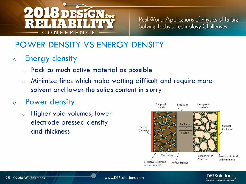
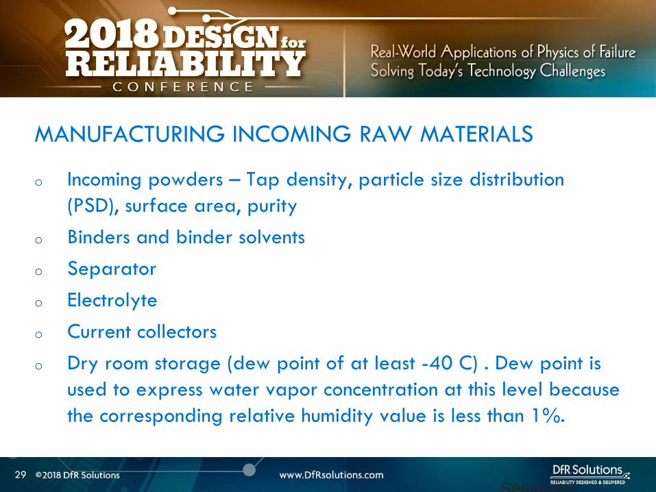
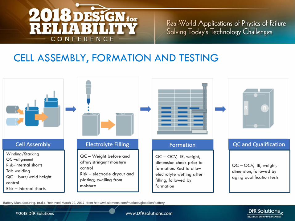

36
LITHIUM ION CELL DESIGN
GUIDELINES
36
37
o Anode should overhang cathode by 05 mm or more on all sides for stacked cell or along top and bottom ends for jellyroll (min of 01 mm per IEEE 16251725)
o Anode should have higher electrochemical capacity than cathode by 10-15
o Example 1 g anode specific capacity is 350 mAhg So total anode capacity is 350 mAh
o 1 g cathode with specific capacity of 280 mAhg has total capacity of 280 mAh
Cathode shall never put out more lithium
ions than the anode can accommodate
CELL DESIGN GUIDELINES
Cathode
Separator
Anode
38
o Separator overhangs anode on all sides (room temperature to
at least 110 C- IEEE 16251725)
o Less than 5 shrinkage in both machine and transverse
directions at 90 C as a minimum
o Separator should have sufficient mechanical
strength to withstand cell assembly operations
CELL DESIGN GUIDELINES
Cathode
Separator
Anode
39
o Product design ndash make sure there is enough room for battery to
expand as it goes through charge ndashdischarge cycles Recommend 10
margin
o Pay particular attention to corners
o Poor manufacturing can reduce design margin
o Cutting operation variability
o Pick and place variability
CELL DESIGN GUIDELINES
40
ARTICLE QUALITY ASESSMENT
CELL CT SCANS AND
TEARDOWN
40
41
o Deep discharged cell
ARTICLE QUALITY ASESSMENT ndash CT SCANS
42
o Exercise - Describe what you see
o Electrode alignment is good on right image
o Variability in jellyroll winding on left and middle images
o Insufficient anode overlap in center of middle image
ARTICLE QUALITY ASESSMENT- CT SCANS
43
o Conduct CT scans and cell teardowns on a handful of units
o What to look for in CT scans
o Uniform cell winding or stacking
o No particulates
o No significant electrode delamination
o Anodes should overhang cathode by 05 mm ideally but a minimum
of 01 mm on each side
o No excessive deformation at pouch corners
o Cutting operationpick and place variability
PHYSICAL ARTICLE QUALITY ASESSMENT ndash CT SCANS
44
o Look at a few electrode pieces using optical microscopy
and SEMEDS
ARTICLE QUALITY ASESSMENT ndash TEARDOWNS
45
LITHIUM ION INTERNAL
AND EXTERNAL
PROTECTION SYSTEMS
45
o Positive Temperature Coefficient (PTC) device - inhibit high current surges
o Charge interrupt device (CID)- opens the electrical path if an excessively high charge voltage raises the internal cell pressure to a threshold value
o Safety vent- allows a controlled release of gas in the event of a rapid increase in cell pressure
o Hot electrolyte vapors and gas will always blow towards the burst disc instead of splitting the sides
o Shutdown Separators
CELL SAFETY PROTECTION MECHANISMS
46
o PTC - doughnut shaped device that sits between two metal
plates and is made of a polymeric material
o At high currents or temperatures resistance of the PTC increases
sharply causing the current to drop
PTC DEVICE
47
Image source nasagov
o The PTC is resettable and reverts
back after the fault is removed
o Once activated it subsequently
activates at a lower current and
temperature
o Works by releasing the connection at the positive terminal and
opening the electrical path
o Pressure valve which will disable the cell permanently of
pressure in the cell is too high
o Is not resettable
CHARGE INTERRUPT DEVICE
48
Image source nasagov
o Pouch cells do not have an internal CID PTC or safety vent
o Can have PTC or fuse elements in series with cell
POUCH CELL PROTECTION
49
Image source nasagov
50
o Separator is usually made of polyethylene (PE) polypropylene (PP) or a combination of the two
o Inner PE layer shuts down at 130degC by closing the pores the outer PP layers do not melt until reaching 155degC
SHUTDOWN SEPARATOR
Image Source Battery University
51
o Separator should increase its resistance by two orders of
magnitude at shutdown temperature (typically 130 C)
SHUTDOWN CURVES
Image Source Arora and Zhang Battery Separators Chem Rev 2004 104 (10) pp 4419ndash4462
52
o Know separator propertieso Thickness
o single vs multiple layer (PE PP or combination)
o ceramic coated or not
o Ceramic coatings can enhance thermal stability and prevent separator collapse till 200 C and beyond
o Ceramic coated separators usually may not have the mechanical strength to withstand winding and assembly- irrelevant for prismatic or stacked designs
SHUTDOWN SEPARATOR PROPERTIES
Impedance (1 kHz AC) vs Shutdown temperature of electrolyte soaked separators (ab) Polyethylene and (c)
polypropylene
53
BATTERY MANAGEMENT
SYSTEM (BMS) AND
PROTECTION CIRCUITRY
53
54
o Operating outside of specifications
Operating Outside Specifications
Image source Electropaedia
55
o Depends on a number of factors
o State of charge (SOC)
o Ambient temperature
o Cell chemistry
o Cell design
o Most severe thermal runaway occurs in an overcharged state
o Case temperatures can reach 600 C
o High temperatures are driven by exothermic reactions of the electrodes and the electrolyte
Severity of Thermal Runaway
56
o Self heating temperature o Fully charged 18650 cells brought to self heating temperature
(70 to 90 C) in adiabatic environment go into thermal runaway in 2 days
o Fully charged 18650 in adiabatic environment brought to 150 C (with separator melting) will run away in minutes
o UL standard requires fully charged cells to withstand 4 hour storage at 75 C and 10 min storage at 130 C
o IEEE standard requires 1 hour exposure at 130 C
o Overcharge o Charging a 42 V system to 5 V will almost certainly cause
immediate thermal runaway
Thermal Runaway Initiation ndash Some Numbers
57
o EV electric bus caught fire in Shenzhen China during
charging
o BMS Failure
o Without a BMS there is no
safe lithium ion battery
EV Bus Failure
58
o Consist of charger and a battery protection printed circuit board (PCB)
o Also called a battery protection circuit module (PCM)
o Important functions of protection systems include monitoring controlling and terminating charge and discharge as needed
o Failure of protection circuitry to either sense or respond to an out of range condition causes battery failure
ELECTRONIC PROTECTION SYSTEMS
59
o Maintain cells within operating window and prevent cells
from going into
o Over voltage
o Over current
o Over temperature
o Over discharge
o Balance individual cells to enhance overall capacity
o Disconnect batteries in a safe way in emergency situations
o Predict remaining capacity or state of charge
BMS FUNCTIONS
BMS Webinar httpswwwdfrsolutionscombattery-management-systems-and-safety-and-reliability-webinar
60
o Most obvious failure mode is exceeding specified voltage
o Charging a 42 V system to 5 V will almost certainly cause immediate thermal runaway
o Charging at excess currents
o Overcharge effects
o Anode ndash lithium plating rather than intercalation
o Cathode ndashexcess de-intercalation causes crystal structure to collapse and release heat
o Heat and gas release (both Joule heating and parasitic reactions)
o Electrolyte and electrode decomposition
OVER CHARGE - VOLTAGE
61
o Over voltage may be applied to the battery from a defective charger or due to improper monitoring on a single cell
o Slight overcharge (from minor deviations in voltage monitoring) causes capacity loss rather than direct thermal runaway
o Overvoltage protection can be implemented by opening a charge MOSFET or a fuse
o Overcharge protection is so critical that multiple independent circuits are typically used to prevent single points of failure
OVER VOLTAGE
62
o Hazard from over discharge is highly underestimated
o When a cell goes into deep discharge copper ions from the negative electrode current collector dissolve On recharge copper dendrites can form
o Over discharge can also cause breakdown of the SEI layer and gas formation
OVER DISCHARGE
Image Source Rui Guo1 Languang
Lu1 Minggao Ouyanga1 and Xuning
Feng1 Sci Rep 2016
63
How Does a Battery Go into
Deep Discharge
63
64
o Uncontrolled storage without appropriate recharge
procedures
o Mechanically damaged cells (from electronics impinging
on cell)
OVER DISCHARGE SCENARIOS
65
o Three kinds of discharge occur during storage o PCM sleep current and leakage currents
o Battery self discharge
o Manufacturing quality
o Temp
o State of charge
o Device sleep currents
o At 3 V (or other threshold cutoff) load is disconnected although above lsquoconsumption currentsrsquo are active
o At deep discharge cutoff value of 2 V (or other manufacturer specified value) PCM and device sleep currents are turned off but battery self discharge continues
Discharge During Storage
66
o Lithium ion self discharge around 1-2 per month + a
few cent for PCM
o High SOC and temperatures degrade storage life (and
cycle life)
o Rule of thumb ndash 10 C increase in temperature doubles self
discharge rate
o Store at conditions close to 25 C and 40 SOC
Battery Self Discharge
67
o To keep the contamination as low as possible to reduce
leakage current de-ionized water wash should be used
in the board cleaning process
o Verify the board cleanliness to make sure the levels of
contamination is low
o Investigate if humidity is an issue and that conformal
needs to be used
PCM (BMS) Self Discharge
68
o Have a pre-check charging function on batteries where deep discharge cutoff voltage was reached Charger circuit checks if a deeply discharged battery is reaches a threshold value in give time Otherwise considered a lsquodamagedrsquo battery
o Mitigating hazard from copper shunts
o Proper battery storage and recharge procedures
o Minimize PCM leakage currents
o Ensure cell quality
o Prevent cell mechanical damage
Deep Discharge Checklist
69
o Over current can causeo Degradation in cycle life
o Thermal runaway
o Threshold limits for current are functions of both current and time Protection circuit system can use different combinations of time and current to produce a fault Example - high currentshort time or lower currentlong time
o Some faults are recoverable such as when a MOSFET is turned on and others are non-recoverable such as when a fuse is ignited
o Causes of over-current could be a defective charger or due to an internal short
OVER CURRENT PROTECTIONS
70
o A good battery management system will limit charge current and voltage at high and low temperature extremes per Japan Electronics and Information Technology Industries Association (JEITA) guidelines
OVER CURRENT
(60 degC)
CoolCold Warm Hot
(0 degC)
Reduce charging
current andor
voltage
Reduce charging
current andor
voltage
71
o Current limits are incorporated into the protection
circuits located in pack or device
o Circuits monitor current in and out of battery and open up
MOSFET to interrupt current
o Backup protection usually includes a fuse or PTC placed
in series with battery pack
SHORT CIRCUIT PROTECTION
72
BATTERY LIFE DEGRADATION
AND STORAGE
72
73
o Battery life example
o Nominal capacity is 2900 mAh End of life capacity at 80 of initial capacity is 2300 mAh
o Is this data sufficient to give you a life of 500 cycles
BATTERY LIFE AND AGING ISSUES
74
o Calendar aging vs cycle life agingo Insertion or ejection of the Lithium ions into and out of the intercalation
spaces during cycling causes the electrode materials to swell or contract
o Repetitive cycling can weaken the electrode structure reducing its adhesion to the current collector This can lead to reduction in charge capacity
BATTERY LIFE DEGRADATION
75
o Storage degradation high temperature aging causes
growth of the passivating layer
o It consumes lithium and electrolyte and leads to capacity loss
and impedance increase (both capacity and power fade)
Pores can be blocked as a result
o Low rate batteries may not see a big impact
(voltage drop = IR)
BATTERY LIFE DEGRADATION CALENDAR AGING
76
o Have two distinct mechanisms
that impact cell life
o Battery aging tests should
involve high temperature
storage tests
BATTERY LIFE DEGRADATION CALENDAR AGING
Image source Electropaedia
77
o Characterize both reversible and irreversible storage loss
o In this example 25 irreversible and 5 reversible
capacity loss
REVERSIBLE VS IRREVERSIBLE STORAGE LOSS
Assume a = 2900 mAh
d = 70 a = 2030 mAh
e = 95 a = 2700 mAh
a
d
e
78
LITHIUM ION CHEMISTRIES
78
79
o Term Lithium-Ion encompasses many different chemistries
o Anode ndash graphite (Lithium Titanate LTO for very fast charge cells)
o Cathode - Cathodes are lithiated metal oxides or lithiated metal
phosphates
o Lithium Cobalt Oxide (LCO)
o Lithium Iron Phosphate(LFP)
o Nickel Manganese Cobalt (NMC)
o Lithium Manganese Oxide(LMO)
o Cathode chemistry is where you get enhancements in safety
energy and power density
Battery Chemistry
80
o Lithium Cobalt Oxide (LCO) ndash commonly used in consumer electronics
o High energy density
o Low power
o Least safe
o Moderate cycle life
Battery Chemistry
o Lithium Iron Phosphate(LFP) ndashndash automotive power tools UPS e-cigs
o Safest chemistry
o High power density
o Very high cycle life
o Lower voltageLower energy density
o Higher self discharge rate
81
o Nickel Manganese Cobalt (NMC) ndashcommon in tools EV applications
e-cigs ndash usually 13 proportion but customization is possible
o Can be optimized for power or energy
o Good safety
o Good cycle life
Battery Chemistry
o Lithium Manganese Oxide(LiMn2O4) ndashndash power tools EV and hybrid vehicles e-cigs
o Low internal resistancehigh power capability (from Manganese)
o Good safety
o Lower energy ndash blends with NMC are used to enhance energy
82
Battery Chemistry Summary
Chemistry LCO NMC LFP LMO
Nominal Voltage(V) 36-37 36-37 32-32 36-37
Charge Voltage(V) 42 42 35-36 42
Safety Poor Good Highest Good
Cycle Life gt500 gt500 gt1000 gt500
Peak Load current (Best result) 2C
(lt1C)
gt30C
(lt10 C)
gt30C
(lt10 C)
Specific energy (WhKg) 150-250 90-120 100-150
Thermal Runaway Temp (ordmC) 150 210 gt270
Used Since 1991 2003 1999 1996
Designation ICR INR IFR IMR
o Knowing chemistry helps to map out worst case scenario
o For pouch cells look at MSDS
83
o Do not see the word LCO
Battery Chemistry in Current EV Systems
84
ESTIMATING STORED ENERGY
84
85
o Risk assessment
o How much energy and wattage does the battery have
o How fast is the energy released
o Is the product worn on or close to the body
o What is the chemistry
o New product category Are there specific user behaviorsproduct
design interactions that increase the risk and impact of thermal away
o Risk mitigation
o Trust but verify
o Do not trust till you verify
o Map out the worst case
BATTERY RISK ASESSMENT
86
o Stored energy is a combination of electrical and chemical
energy
o Electrical Energy
o Chemical energy may be approximated by using heats of
combustion of various flammable components in cell
STORED ENERGY
87
o Specification
o 37 V
o 296 Wh
o 800 mAh
o Useful information 1 Wh = 36 kJ
o Total stored energy = 296 36 = 1065 kJ
STORED ENERGY PRISMATIC EXAMPLE
88
o Assume 1 to 5 g of electrolyte for small prismatic or pouch cell Assume 05 to 1 g of separator
o Electrolyte solvents are generally organic carbonates such as diethyl carbonate (DEC) ethylene carbonate dimethyl carbonate and ethylmethyl carbonate
o Using the heat of combustion of DEC at 2092 kJg 21 to 105 kJ of energy from electrolyte combustion
o Separator is made of polyethylene polypropylene or combination of the two
o By using polypropylene heat of combustion as an approximation at 4266 kJg 21 to 42 kJ energy for the separator
o Total chemical energy approximation is 42 to 147 kJ
STORED CHEMICAL ENERGY SMALL PRISMATIC
89
o Estimate of total energy released is 52 to 117 kJ
STORED ENERGY SMALL PRISMATIC
Cell Type Energy Low (kJ) High (kJ) Amount (g)
Chemical Energy Combustible
materials Total
42 147
Separator 21 42 05 to 1
Electrolyte 21 105 1 to 5
Electrical (nominal voltage to fully
charged state)
1065 121
Prismatic Total 5265 117
90
o Specification o 37 V
o 962 Wh
o 2600 mAh
o Useful information 1 Wh = 36 kJo Heat of combustion of DEC = 2092 kJg
o Polypropylene heat of combustion = 4266 kJg
o For comparison a 190 g stick of dynamite can release 1 MJ of energy1
STORED ENERGY 18650 EXAMPLE SOLUTION
Cell Type Energy Low (kJ) High (kJ) Amount (g)
Chemical Energy Combustible materials Total 122 23561
Separator 5972 6825 14 to 16
Electrolyte 6236 16736 3 to 8
Electrical (nominal voltage to fully charged
state)
3462 393
18650 Total 157 207
1 httpsenwikipediaorgwikiDynamite
91
Is the 18650 Hazard
Relevant to You
91
92
o Smaller batteries - 20 mAh to 500 mAh
o Energy released is 10- to 100 times lower than the 18650o Smaller capacity batteries release smaller amounts of energy
o 150 -200 mAh batteries generally used for headphone applications such as in illustration
Small Batteries
93
o Calculate total energy released from your cell
o Electrical energy + chemical energy
o Use thermal analysis to estimate temperature rise and
compare against allowable surface temperaturesstandards
Worst Case Analysis
Material Burn Threshold for
contact of 05 s (ordmC)
Bare metal 67-73
Ceramics glass and stone 84-90
Plastics 91-99
Wood 128-155
European standard BS EN 132022000
94
o Potential for burn hazard may be estimated
Skin Burn Temperatures
Effect Description Skin
Temperature
(ordmC)
Pain Tingling hot sensation 44
1st degree burn Superficial injury to outer layer skin
is reddened painful
44-55
2nd degree burn Outer layer is burned through
second layer damaged skin is moist
and reddened with blisters intense
pain
55-60
3rd degree burn All skin layers are damaged 60
95
VENT GAS RISK
95
96
o Vent gases mainly consist of H2 hydrocarbons (also called THC or
total hydrocarbon concentration in figure below) CO2 and CO
o Flammable gases include H2 CO and hydrocarbons
Vent Gas Flammability
Ref 1 US DOTFAA Study Lithium Battery Thermal Runaway Vent Gas Analysis Nov 2016
Major gas species concentration for18650 LiCoO2 cell
97
o When a lithium ion battery vents the gas mixture will mix with surrounding air and may or may not ignite
o The following conditions have to be met for an ignition evento Air fuel mixture is within the Lower Flammability Limit (LFL) and (Upper
Flammability Limit) UFL limits
o Ignition source is present
o The most dangerous materials are those with the lowest flash point and widest flammable ranges
o A hot cell case or hot metal sparks ejected from the cell could create an ignition event if the mixture is within flammability limits
Ignition Risk
98
CHEMICAL SPILL RISK
98
99
o In the absence of a fire potential hazard from a damaged lithium ion battery includes the following
o Release of a electrolyte containing a corrosive salt Electrolyte is extremely corrosive and may cause permanent blindness If ingested through the mouth liver and kidney damage is possible
o Reaction of the electrolyte with waterhumidity may generate hydrofluoric acid which are highly toxic and corrosive to the eyes nose throat and skin
o Release of volatile organics toxic gases such as CO HF
Chemical Spill Risk
Ref Various MSDS sheets
100
o Lithiated carbon in a charged anode the Solid Electrolyte
Interphase (SEI) layer or any free lithium (dendritesplating)
will burst into flames when exposed to moist air
o Reaction of lithium with water produces H2 in an exothermic
reaction
o Significant heat is released in this reaction and this can ignite the H2
Chemical Risk ndash Lithium Ion and Primary Lithium
101
Lithium Ion Life Cycle ndash
Cradle to Grave
101
102
o Cell Manufacturing
o brought to a low to moderate state of charge for shippingstorage
o Transportation
o Warehouse storage
o Pack or device assembly
o OEM device shipment
o Device Usage
o Recycling
LITHIUM ION BATTERY LIFE CYCLE
103
o Almost all failures are related to improper packaging (potential for mechanical damage and external shorts) and shipment procedures
o International Air Transportation Association (IATA) shipment procedures for dangerous goods Cell manufacturers must show proof of UN 383 certification
o 1) Lithium ion batteries (not contained in equipment) shall not be shipped with SOC greater than 30
o 2) Shall pass UN 383 battery of tests
o 3) Shall not be shipped on passenger aircraft
Transportation Procedures
See httpwwwiataorgwhatwedocargodgrDocumentslithium-battery-shipping-guidelinespdf
104
o Small cell shipment exceptions to class 9 dangerous goods classification
o Only Carry-on and Section II are exempt from Class 9 hazardous material
designation
Transportation Procedures
Image source
Battery university
105
o Have procedures in place for safe handling of lithium ion
batteries
o Protection from short circuit high temperature is critical
o Pouch cells must use recessed packaging trays
Storage and Warehouse Handling
106
o Do not single stream recycle lithium ion batteries
o High risk of ignition with surrounding paper and cardboard
o Lithium Ion batteries can be recycled but only at specified
locations Visit httpswwwcall2recycleorglocator
(Rechargeable Battery Recycling Corporation)
o 86 of US and Canadian residents live within 10 miles of
drop-off location
o httpswwwcall2recycleorg for battery recycling resources
Lithium Ion Recycling Procedures
107
o Do not discard as trash
o When collecting batteries make sure they are taped or
insulated
o Recommend drop-off instead
Lithium Ion Recycling Procedures
108
COMPLIANCE TESTING
108
109
o Tests that have the same name under different standards are not always the same
o There are differences in terms of the state of charge aging of the cells and sample sizes and these can have significant differences
o The vendor must state the test standard specify a test description in addition to the name of the test
BATTERY COMPLIANCE TESTING
110
o UNDOT 383 Covers transportation safety testing for all lithium
metal and lithium ion cells and batteries This is mandatory
o UL safety standards
o UL 1642 ndash This standard is used for testing lithium cells Battery level tests
are covered by UL 2054
o UL 2054 (Household and Commercial Batteries) ndash For lithium batteries UL
2054 defers all component cell level testing to UL 1642
o CEIIEC 62133 ndash this standard is voluntary in the US but some
countries specify this standard
BATTERY COMPLIANCE TESTING
111
o IEEE 16251725 ndash These standards are applicable to rechargeable batteries for Multi-cell mobile computing devices and for Cellular phones respectively (CTIA or Wireless Association)
o These standards take the most comprehensive approach to battery testing and emphasize that battery pack safety is a function of a) the individual cells b) the battery pack c) the host device d) power supply accessories e) the user f) the environment
o Both standards require design analysis tools such as FMEA or fault tree analysis They also encompass industry best practices in manufacturing and in the areas of cell pack system and charging accessory design
BATTERY COMPLIANCE TESTING
112
The more you know the better
Parting Thought
Questions
bull Contact Vidyu Challa
vchalladfrsolutionscom
301-640-5834
bull wwwdfrsolutionscom resources page for
battery and other electronic reliability
resources
114
APPENDIX
114
115
Battery Seal Quality
o Moisture ingress through
o Laminate face (extremely low due to metal barrier)
o Interfaces (no metal barrier)
o Terminals (good sealing practices mandatory)
o Compensate through large seal width ( generally 2 mm
min)
o Seal width checks
116
o Flash points for common components of lithium ion battery
electrolytes are below
FLASH POINTS
Ref CRC handbook of chemistry and physics
Electrolyte Component Boiling Point Flash Point
Propylene carbonate (PC) 242degC 135degC
468degF 275degF
Ethylene carbonate (EC) 248degC 145degC
478degF 293degF
Di-Methyl carbonate (DMC) 91degC 18degC
195degF 64degF
Diethyl carbonate (DEC) 126degC 25degC
259degF 77degF
Ethyl methyl carbonate (EMC) 107degC 25degC
225degF 77degF
117
o Flammability limits for vent gases from Li Ion batteries are in
table below
Ref Combustion Flames and Explosion of Gases 2nd Edition Academic Press NY 1961
Compound Lower flammability limit
(fuel volume )
Upper flammability limit
(fuel volume )
Hydrogen 40 750
Carbon monoxide 125 740
Methane 53 150
Ethylene 31 320
Ethane 30 125
Propylene 24 103
C4 hydrocarbons ~ 16-19 ~ 84 ndash 97
C5 hydrocarbons ~ 14-15 ~ 75 ndash 87
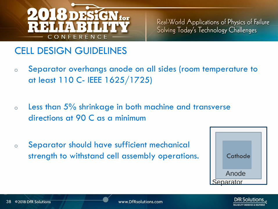
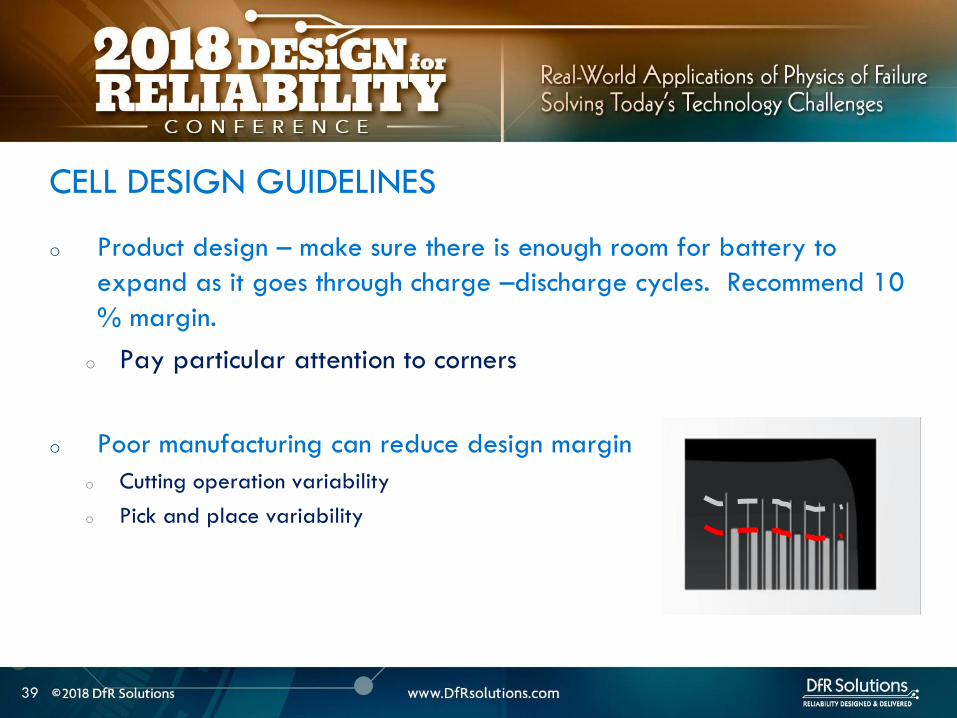
40
ARTICLE QUALITY ASESSMENT
CELL CT SCANS AND
TEARDOWN
40
41
o Deep discharged cell
ARTICLE QUALITY ASESSMENT ndash CT SCANS
42
o Exercise - Describe what you see
o Electrode alignment is good on right image
o Variability in jellyroll winding on left and middle images
o Insufficient anode overlap in center of middle image
ARTICLE QUALITY ASESSMENT- CT SCANS
43
o Conduct CT scans and cell teardowns on a handful of units
o What to look for in CT scans
o Uniform cell winding or stacking
o No particulates
o No significant electrode delamination
o Anodes should overhang cathode by 05 mm ideally but a minimum
of 01 mm on each side
o No excessive deformation at pouch corners
o Cutting operationpick and place variability
PHYSICAL ARTICLE QUALITY ASESSMENT ndash CT SCANS
44
o Look at a few electrode pieces using optical microscopy
and SEMEDS
ARTICLE QUALITY ASESSMENT ndash TEARDOWNS
45
LITHIUM ION INTERNAL
AND EXTERNAL
PROTECTION SYSTEMS
45
o Positive Temperature Coefficient (PTC) device - inhibit high current surges
o Charge interrupt device (CID)- opens the electrical path if an excessively high charge voltage raises the internal cell pressure to a threshold value
o Safety vent- allows a controlled release of gas in the event of a rapid increase in cell pressure
o Hot electrolyte vapors and gas will always blow towards the burst disc instead of splitting the sides
o Shutdown Separators
CELL SAFETY PROTECTION MECHANISMS
46
o PTC - doughnut shaped device that sits between two metal
plates and is made of a polymeric material
o At high currents or temperatures resistance of the PTC increases
sharply causing the current to drop
PTC DEVICE
47
Image source nasagov
o The PTC is resettable and reverts
back after the fault is removed
o Once activated it subsequently
activates at a lower current and
temperature
o Works by releasing the connection at the positive terminal and
opening the electrical path
o Pressure valve which will disable the cell permanently of
pressure in the cell is too high
o Is not resettable
CHARGE INTERRUPT DEVICE
48
Image source nasagov
o Pouch cells do not have an internal CID PTC or safety vent
o Can have PTC or fuse elements in series with cell
POUCH CELL PROTECTION
49
Image source nasagov
50
o Separator is usually made of polyethylene (PE) polypropylene (PP) or a combination of the two
o Inner PE layer shuts down at 130degC by closing the pores the outer PP layers do not melt until reaching 155degC
SHUTDOWN SEPARATOR
Image Source Battery University
51
o Separator should increase its resistance by two orders of
magnitude at shutdown temperature (typically 130 C)
SHUTDOWN CURVES
Image Source Arora and Zhang Battery Separators Chem Rev 2004 104 (10) pp 4419ndash4462
52
o Know separator propertieso Thickness
o single vs multiple layer (PE PP or combination)
o ceramic coated or not
o Ceramic coatings can enhance thermal stability and prevent separator collapse till 200 C and beyond
o Ceramic coated separators usually may not have the mechanical strength to withstand winding and assembly- irrelevant for prismatic or stacked designs
SHUTDOWN SEPARATOR PROPERTIES
Impedance (1 kHz AC) vs Shutdown temperature of electrolyte soaked separators (ab) Polyethylene and (c)
polypropylene
53
BATTERY MANAGEMENT
SYSTEM (BMS) AND
PROTECTION CIRCUITRY
53
54
o Operating outside of specifications
Operating Outside Specifications
Image source Electropaedia
55
o Depends on a number of factors
o State of charge (SOC)
o Ambient temperature
o Cell chemistry
o Cell design
o Most severe thermal runaway occurs in an overcharged state
o Case temperatures can reach 600 C
o High temperatures are driven by exothermic reactions of the electrodes and the electrolyte
Severity of Thermal Runaway
56
o Self heating temperature o Fully charged 18650 cells brought to self heating temperature
(70 to 90 C) in adiabatic environment go into thermal runaway in 2 days
o Fully charged 18650 in adiabatic environment brought to 150 C (with separator melting) will run away in minutes
o UL standard requires fully charged cells to withstand 4 hour storage at 75 C and 10 min storage at 130 C
o IEEE standard requires 1 hour exposure at 130 C
o Overcharge o Charging a 42 V system to 5 V will almost certainly cause
immediate thermal runaway
Thermal Runaway Initiation ndash Some Numbers
57
o EV electric bus caught fire in Shenzhen China during
charging
o BMS Failure
o Without a BMS there is no
safe lithium ion battery
EV Bus Failure
58
o Consist of charger and a battery protection printed circuit board (PCB)
o Also called a battery protection circuit module (PCM)
o Important functions of protection systems include monitoring controlling and terminating charge and discharge as needed
o Failure of protection circuitry to either sense or respond to an out of range condition causes battery failure
ELECTRONIC PROTECTION SYSTEMS
59
o Maintain cells within operating window and prevent cells
from going into
o Over voltage
o Over current
o Over temperature
o Over discharge
o Balance individual cells to enhance overall capacity
o Disconnect batteries in a safe way in emergency situations
o Predict remaining capacity or state of charge
BMS FUNCTIONS
BMS Webinar httpswwwdfrsolutionscombattery-management-systems-and-safety-and-reliability-webinar
60
o Most obvious failure mode is exceeding specified voltage
o Charging a 42 V system to 5 V will almost certainly cause immediate thermal runaway
o Charging at excess currents
o Overcharge effects
o Anode ndash lithium plating rather than intercalation
o Cathode ndashexcess de-intercalation causes crystal structure to collapse and release heat
o Heat and gas release (both Joule heating and parasitic reactions)
o Electrolyte and electrode decomposition
OVER CHARGE - VOLTAGE
61
o Over voltage may be applied to the battery from a defective charger or due to improper monitoring on a single cell
o Slight overcharge (from minor deviations in voltage monitoring) causes capacity loss rather than direct thermal runaway
o Overvoltage protection can be implemented by opening a charge MOSFET or a fuse
o Overcharge protection is so critical that multiple independent circuits are typically used to prevent single points of failure
OVER VOLTAGE
62
o Hazard from over discharge is highly underestimated
o When a cell goes into deep discharge copper ions from the negative electrode current collector dissolve On recharge copper dendrites can form
o Over discharge can also cause breakdown of the SEI layer and gas formation
OVER DISCHARGE
Image Source Rui Guo1 Languang
Lu1 Minggao Ouyanga1 and Xuning
Feng1 Sci Rep 2016
63
How Does a Battery Go into
Deep Discharge
63
64
o Uncontrolled storage without appropriate recharge
procedures
o Mechanically damaged cells (from electronics impinging
on cell)
OVER DISCHARGE SCENARIOS
65
o Three kinds of discharge occur during storage o PCM sleep current and leakage currents
o Battery self discharge
o Manufacturing quality
o Temp
o State of charge
o Device sleep currents
o At 3 V (or other threshold cutoff) load is disconnected although above lsquoconsumption currentsrsquo are active
o At deep discharge cutoff value of 2 V (or other manufacturer specified value) PCM and device sleep currents are turned off but battery self discharge continues
Discharge During Storage
66
o Lithium ion self discharge around 1-2 per month + a
few cent for PCM
o High SOC and temperatures degrade storage life (and
cycle life)
o Rule of thumb ndash 10 C increase in temperature doubles self
discharge rate
o Store at conditions close to 25 C and 40 SOC
Battery Self Discharge
67
o To keep the contamination as low as possible to reduce
leakage current de-ionized water wash should be used
in the board cleaning process
o Verify the board cleanliness to make sure the levels of
contamination is low
o Investigate if humidity is an issue and that conformal
needs to be used
PCM (BMS) Self Discharge
68
o Have a pre-check charging function on batteries where deep discharge cutoff voltage was reached Charger circuit checks if a deeply discharged battery is reaches a threshold value in give time Otherwise considered a lsquodamagedrsquo battery
o Mitigating hazard from copper shunts
o Proper battery storage and recharge procedures
o Minimize PCM leakage currents
o Ensure cell quality
o Prevent cell mechanical damage
Deep Discharge Checklist
69
o Over current can causeo Degradation in cycle life
o Thermal runaway
o Threshold limits for current are functions of both current and time Protection circuit system can use different combinations of time and current to produce a fault Example - high currentshort time or lower currentlong time
o Some faults are recoverable such as when a MOSFET is turned on and others are non-recoverable such as when a fuse is ignited
o Causes of over-current could be a defective charger or due to an internal short
OVER CURRENT PROTECTIONS
70
o A good battery management system will limit charge current and voltage at high and low temperature extremes per Japan Electronics and Information Technology Industries Association (JEITA) guidelines
OVER CURRENT
(60 degC)
CoolCold Warm Hot
(0 degC)
Reduce charging
current andor
voltage
Reduce charging
current andor
voltage
71
o Current limits are incorporated into the protection
circuits located in pack or device
o Circuits monitor current in and out of battery and open up
MOSFET to interrupt current
o Backup protection usually includes a fuse or PTC placed
in series with battery pack
SHORT CIRCUIT PROTECTION
72
BATTERY LIFE DEGRADATION
AND STORAGE
72
73
o Battery life example
o Nominal capacity is 2900 mAh End of life capacity at 80 of initial capacity is 2300 mAh
o Is this data sufficient to give you a life of 500 cycles
BATTERY LIFE AND AGING ISSUES
74
o Calendar aging vs cycle life agingo Insertion or ejection of the Lithium ions into and out of the intercalation
spaces during cycling causes the electrode materials to swell or contract
o Repetitive cycling can weaken the electrode structure reducing its adhesion to the current collector This can lead to reduction in charge capacity
BATTERY LIFE DEGRADATION
75
o Storage degradation high temperature aging causes
growth of the passivating layer
o It consumes lithium and electrolyte and leads to capacity loss
and impedance increase (both capacity and power fade)
Pores can be blocked as a result
o Low rate batteries may not see a big impact
(voltage drop = IR)
BATTERY LIFE DEGRADATION CALENDAR AGING
76
o Have two distinct mechanisms
that impact cell life
o Battery aging tests should
involve high temperature
storage tests
BATTERY LIFE DEGRADATION CALENDAR AGING
Image source Electropaedia
77
o Characterize both reversible and irreversible storage loss
o In this example 25 irreversible and 5 reversible
capacity loss
REVERSIBLE VS IRREVERSIBLE STORAGE LOSS
Assume a = 2900 mAh
d = 70 a = 2030 mAh
e = 95 a = 2700 mAh
a
d
e
78
LITHIUM ION CHEMISTRIES
78
79
o Term Lithium-Ion encompasses many different chemistries
o Anode ndash graphite (Lithium Titanate LTO for very fast charge cells)
o Cathode - Cathodes are lithiated metal oxides or lithiated metal
phosphates
o Lithium Cobalt Oxide (LCO)
o Lithium Iron Phosphate(LFP)
o Nickel Manganese Cobalt (NMC)
o Lithium Manganese Oxide(LMO)
o Cathode chemistry is where you get enhancements in safety
energy and power density
Battery Chemistry
80
o Lithium Cobalt Oxide (LCO) ndash commonly used in consumer electronics
o High energy density
o Low power
o Least safe
o Moderate cycle life
Battery Chemistry
o Lithium Iron Phosphate(LFP) ndashndash automotive power tools UPS e-cigs
o Safest chemistry
o High power density
o Very high cycle life
o Lower voltageLower energy density
o Higher self discharge rate
81
o Nickel Manganese Cobalt (NMC) ndashcommon in tools EV applications
e-cigs ndash usually 13 proportion but customization is possible
o Can be optimized for power or energy
o Good safety
o Good cycle life
Battery Chemistry
o Lithium Manganese Oxide(LiMn2O4) ndashndash power tools EV and hybrid vehicles e-cigs
o Low internal resistancehigh power capability (from Manganese)
o Good safety
o Lower energy ndash blends with NMC are used to enhance energy
82
Battery Chemistry Summary
Chemistry LCO NMC LFP LMO
Nominal Voltage(V) 36-37 36-37 32-32 36-37
Charge Voltage(V) 42 42 35-36 42
Safety Poor Good Highest Good
Cycle Life gt500 gt500 gt1000 gt500
Peak Load current (Best result) 2C
(lt1C)
gt30C
(lt10 C)
gt30C
(lt10 C)
Specific energy (WhKg) 150-250 90-120 100-150
Thermal Runaway Temp (ordmC) 150 210 gt270
Used Since 1991 2003 1999 1996
Designation ICR INR IFR IMR
o Knowing chemistry helps to map out worst case scenario
o For pouch cells look at MSDS
83
o Do not see the word LCO
Battery Chemistry in Current EV Systems
84
ESTIMATING STORED ENERGY
84
85
o Risk assessment
o How much energy and wattage does the battery have
o How fast is the energy released
o Is the product worn on or close to the body
o What is the chemistry
o New product category Are there specific user behaviorsproduct
design interactions that increase the risk and impact of thermal away
o Risk mitigation
o Trust but verify
o Do not trust till you verify
o Map out the worst case
BATTERY RISK ASESSMENT
86
o Stored energy is a combination of electrical and chemical
energy
o Electrical Energy
o Chemical energy may be approximated by using heats of
combustion of various flammable components in cell
STORED ENERGY
87
o Specification
o 37 V
o 296 Wh
o 800 mAh
o Useful information 1 Wh = 36 kJ
o Total stored energy = 296 36 = 1065 kJ
STORED ENERGY PRISMATIC EXAMPLE
88
o Assume 1 to 5 g of electrolyte for small prismatic or pouch cell Assume 05 to 1 g of separator
o Electrolyte solvents are generally organic carbonates such as diethyl carbonate (DEC) ethylene carbonate dimethyl carbonate and ethylmethyl carbonate
o Using the heat of combustion of DEC at 2092 kJg 21 to 105 kJ of energy from electrolyte combustion
o Separator is made of polyethylene polypropylene or combination of the two
o By using polypropylene heat of combustion as an approximation at 4266 kJg 21 to 42 kJ energy for the separator
o Total chemical energy approximation is 42 to 147 kJ
STORED CHEMICAL ENERGY SMALL PRISMATIC
89
o Estimate of total energy released is 52 to 117 kJ
STORED ENERGY SMALL PRISMATIC
Cell Type Energy Low (kJ) High (kJ) Amount (g)
Chemical Energy Combustible
materials Total
42 147
Separator 21 42 05 to 1
Electrolyte 21 105 1 to 5
Electrical (nominal voltage to fully
charged state)
1065 121
Prismatic Total 5265 117
90
o Specification o 37 V
o 962 Wh
o 2600 mAh
o Useful information 1 Wh = 36 kJo Heat of combustion of DEC = 2092 kJg
o Polypropylene heat of combustion = 4266 kJg
o For comparison a 190 g stick of dynamite can release 1 MJ of energy1
STORED ENERGY 18650 EXAMPLE SOLUTION
Cell Type Energy Low (kJ) High (kJ) Amount (g)
Chemical Energy Combustible materials Total 122 23561
Separator 5972 6825 14 to 16
Electrolyte 6236 16736 3 to 8
Electrical (nominal voltage to fully charged
state)
3462 393
18650 Total 157 207
1 httpsenwikipediaorgwikiDynamite
91
Is the 18650 Hazard
Relevant to You
91
92
o Smaller batteries - 20 mAh to 500 mAh
o Energy released is 10- to 100 times lower than the 18650o Smaller capacity batteries release smaller amounts of energy
o 150 -200 mAh batteries generally used for headphone applications such as in illustration
Small Batteries
93
o Calculate total energy released from your cell
o Electrical energy + chemical energy
o Use thermal analysis to estimate temperature rise and
compare against allowable surface temperaturesstandards
Worst Case Analysis
Material Burn Threshold for
contact of 05 s (ordmC)
Bare metal 67-73
Ceramics glass and stone 84-90
Plastics 91-99
Wood 128-155
European standard BS EN 132022000
94
o Potential for burn hazard may be estimated
Skin Burn Temperatures
Effect Description Skin
Temperature
(ordmC)
Pain Tingling hot sensation 44
1st degree burn Superficial injury to outer layer skin
is reddened painful
44-55
2nd degree burn Outer layer is burned through
second layer damaged skin is moist
and reddened with blisters intense
pain
55-60
3rd degree burn All skin layers are damaged 60
95
VENT GAS RISK
95
96
o Vent gases mainly consist of H2 hydrocarbons (also called THC or
total hydrocarbon concentration in figure below) CO2 and CO
o Flammable gases include H2 CO and hydrocarbons
Vent Gas Flammability
Ref 1 US DOTFAA Study Lithium Battery Thermal Runaway Vent Gas Analysis Nov 2016
Major gas species concentration for18650 LiCoO2 cell
97
o When a lithium ion battery vents the gas mixture will mix with surrounding air and may or may not ignite
o The following conditions have to be met for an ignition evento Air fuel mixture is within the Lower Flammability Limit (LFL) and (Upper
Flammability Limit) UFL limits
o Ignition source is present
o The most dangerous materials are those with the lowest flash point and widest flammable ranges
o A hot cell case or hot metal sparks ejected from the cell could create an ignition event if the mixture is within flammability limits
Ignition Risk
98
CHEMICAL SPILL RISK
98
99
o In the absence of a fire potential hazard from a damaged lithium ion battery includes the following
o Release of a electrolyte containing a corrosive salt Electrolyte is extremely corrosive and may cause permanent blindness If ingested through the mouth liver and kidney damage is possible
o Reaction of the electrolyte with waterhumidity may generate hydrofluoric acid which are highly toxic and corrosive to the eyes nose throat and skin
o Release of volatile organics toxic gases such as CO HF
Chemical Spill Risk
Ref Various MSDS sheets
100
o Lithiated carbon in a charged anode the Solid Electrolyte
Interphase (SEI) layer or any free lithium (dendritesplating)
will burst into flames when exposed to moist air
o Reaction of lithium with water produces H2 in an exothermic
reaction
o Significant heat is released in this reaction and this can ignite the H2
Chemical Risk ndash Lithium Ion and Primary Lithium
101
Lithium Ion Life Cycle ndash
Cradle to Grave
101
102
o Cell Manufacturing
o brought to a low to moderate state of charge for shippingstorage
o Transportation
o Warehouse storage
o Pack or device assembly
o OEM device shipment
o Device Usage
o Recycling
LITHIUM ION BATTERY LIFE CYCLE
103
o Almost all failures are related to improper packaging (potential for mechanical damage and external shorts) and shipment procedures
o International Air Transportation Association (IATA) shipment procedures for dangerous goods Cell manufacturers must show proof of UN 383 certification
o 1) Lithium ion batteries (not contained in equipment) shall not be shipped with SOC greater than 30
o 2) Shall pass UN 383 battery of tests
o 3) Shall not be shipped on passenger aircraft
Transportation Procedures
See httpwwwiataorgwhatwedocargodgrDocumentslithium-battery-shipping-guidelinespdf
104
o Small cell shipment exceptions to class 9 dangerous goods classification
o Only Carry-on and Section II are exempt from Class 9 hazardous material
designation
Transportation Procedures
Image source
Battery university
105
o Have procedures in place for safe handling of lithium ion
batteries
o Protection from short circuit high temperature is critical
o Pouch cells must use recessed packaging trays
Storage and Warehouse Handling
106
o Do not single stream recycle lithium ion batteries
o High risk of ignition with surrounding paper and cardboard
o Lithium Ion batteries can be recycled but only at specified
locations Visit httpswwwcall2recycleorglocator
(Rechargeable Battery Recycling Corporation)
o 86 of US and Canadian residents live within 10 miles of
drop-off location
o httpswwwcall2recycleorg for battery recycling resources
Lithium Ion Recycling Procedures
107
o Do not discard as trash
o When collecting batteries make sure they are taped or
insulated
o Recommend drop-off instead
Lithium Ion Recycling Procedures
108
COMPLIANCE TESTING
108
109
o Tests that have the same name under different standards are not always the same
o There are differences in terms of the state of charge aging of the cells and sample sizes and these can have significant differences
o The vendor must state the test standard specify a test description in addition to the name of the test
BATTERY COMPLIANCE TESTING
110
o UNDOT 383 Covers transportation safety testing for all lithium
metal and lithium ion cells and batteries This is mandatory
o UL safety standards
o UL 1642 ndash This standard is used for testing lithium cells Battery level tests
are covered by UL 2054
o UL 2054 (Household and Commercial Batteries) ndash For lithium batteries UL
2054 defers all component cell level testing to UL 1642
o CEIIEC 62133 ndash this standard is voluntary in the US but some
countries specify this standard
BATTERY COMPLIANCE TESTING
111
o IEEE 16251725 ndash These standards are applicable to rechargeable batteries for Multi-cell mobile computing devices and for Cellular phones respectively (CTIA or Wireless Association)
o These standards take the most comprehensive approach to battery testing and emphasize that battery pack safety is a function of a) the individual cells b) the battery pack c) the host device d) power supply accessories e) the user f) the environment
o Both standards require design analysis tools such as FMEA or fault tree analysis They also encompass industry best practices in manufacturing and in the areas of cell pack system and charging accessory design
BATTERY COMPLIANCE TESTING
112
The more you know the better
Parting Thought
Questions
bull Contact Vidyu Challa
vchalladfrsolutionscom
301-640-5834
bull wwwdfrsolutionscom resources page for
battery and other electronic reliability
resources
114
APPENDIX
114
115
Battery Seal Quality
o Moisture ingress through
o Laminate face (extremely low due to metal barrier)
o Interfaces (no metal barrier)
o Terminals (good sealing practices mandatory)
o Compensate through large seal width ( generally 2 mm
min)
o Seal width checks
116
o Flash points for common components of lithium ion battery
electrolytes are below
FLASH POINTS
Ref CRC handbook of chemistry and physics
Electrolyte Component Boiling Point Flash Point
Propylene carbonate (PC) 242degC 135degC
468degF 275degF
Ethylene carbonate (EC) 248degC 145degC
478degF 293degF
Di-Methyl carbonate (DMC) 91degC 18degC
195degF 64degF
Diethyl carbonate (DEC) 126degC 25degC
259degF 77degF
Ethyl methyl carbonate (EMC) 107degC 25degC
225degF 77degF
117
o Flammability limits for vent gases from Li Ion batteries are in
table below
Ref Combustion Flames and Explosion of Gases 2nd Edition Academic Press NY 1961
Compound Lower flammability limit
(fuel volume )
Upper flammability limit
(fuel volume )
Hydrogen 40 750
Carbon monoxide 125 740
Methane 53 150
Ethylene 31 320
Ethane 30 125
Propylene 24 103
C4 hydrocarbons ~ 16-19 ~ 84 ndash 97
C5 hydrocarbons ~ 14-15 ~ 75 ndash 87
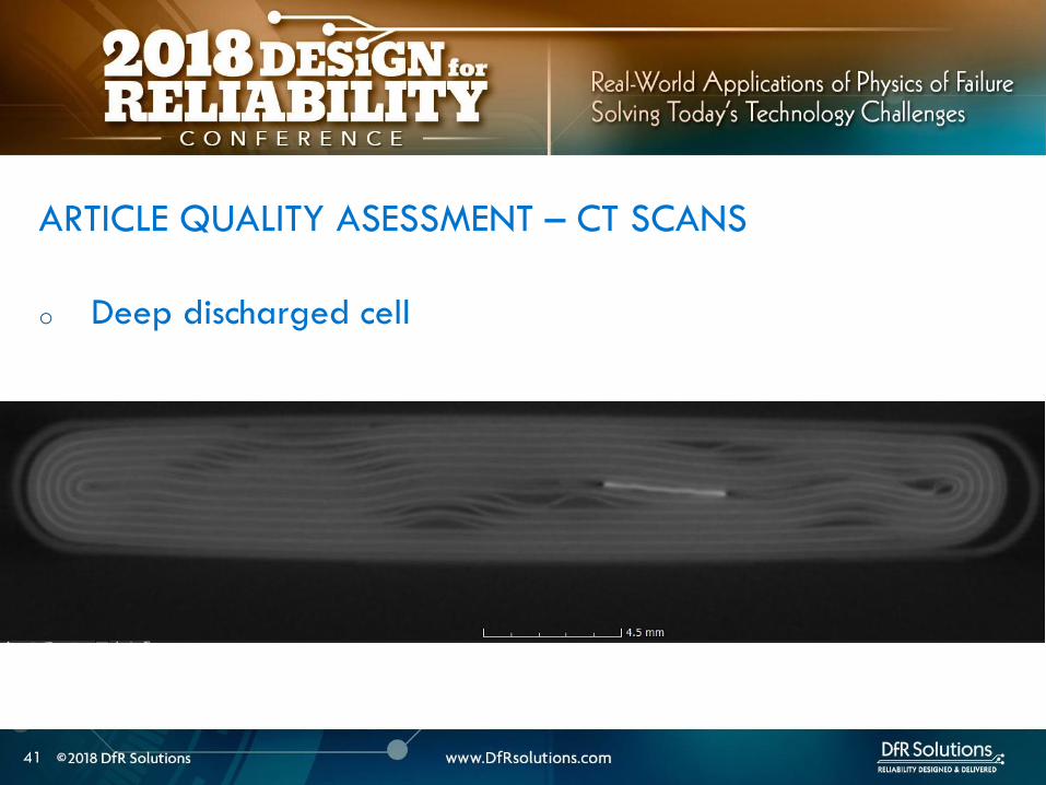
45
LITHIUM ION INTERNAL
AND EXTERNAL
PROTECTION SYSTEMS
45
o Positive Temperature Coefficient (PTC) device - inhibit high current surges
o Charge interrupt device (CID)- opens the electrical path if an excessively high charge voltage raises the internal cell pressure to a threshold value
o Safety vent- allows a controlled release of gas in the event of a rapid increase in cell pressure
o Hot electrolyte vapors and gas will always blow towards the burst disc instead of splitting the sides
o Shutdown Separators
CELL SAFETY PROTECTION MECHANISMS
46
o PTC - doughnut shaped device that sits between two metal
plates and is made of a polymeric material
o At high currents or temperatures resistance of the PTC increases
sharply causing the current to drop
PTC DEVICE
47
Image source nasagov
o The PTC is resettable and reverts
back after the fault is removed
o Once activated it subsequently
activates at a lower current and
temperature
o Works by releasing the connection at the positive terminal and
opening the electrical path
o Pressure valve which will disable the cell permanently of
pressure in the cell is too high
o Is not resettable
CHARGE INTERRUPT DEVICE
48
Image source nasagov
o Pouch cells do not have an internal CID PTC or safety vent
o Can have PTC or fuse elements in series with cell
POUCH CELL PROTECTION
49
Image source nasagov
50
o Separator is usually made of polyethylene (PE) polypropylene (PP) or a combination of the two
o Inner PE layer shuts down at 130degC by closing the pores the outer PP layers do not melt until reaching 155degC
SHUTDOWN SEPARATOR
Image Source Battery University
51
o Separator should increase its resistance by two orders of
magnitude at shutdown temperature (typically 130 C)
SHUTDOWN CURVES
Image Source Arora and Zhang Battery Separators Chem Rev 2004 104 (10) pp 4419ndash4462
52
o Know separator propertieso Thickness
o single vs multiple layer (PE PP or combination)
o ceramic coated or not
o Ceramic coatings can enhance thermal stability and prevent separator collapse till 200 C and beyond
o Ceramic coated separators usually may not have the mechanical strength to withstand winding and assembly- irrelevant for prismatic or stacked designs
SHUTDOWN SEPARATOR PROPERTIES
Impedance (1 kHz AC) vs Shutdown temperature of electrolyte soaked separators (ab) Polyethylene and (c)
polypropylene
53
BATTERY MANAGEMENT
SYSTEM (BMS) AND
PROTECTION CIRCUITRY
53
54
o Operating outside of specifications
Operating Outside Specifications
Image source Electropaedia
55
o Depends on a number of factors
o State of charge (SOC)
o Ambient temperature
o Cell chemistry
o Cell design
o Most severe thermal runaway occurs in an overcharged state
o Case temperatures can reach 600 C
o High temperatures are driven by exothermic reactions of the electrodes and the electrolyte
Severity of Thermal Runaway
56
o Self heating temperature o Fully charged 18650 cells brought to self heating temperature
(70 to 90 C) in adiabatic environment go into thermal runaway in 2 days
o Fully charged 18650 in adiabatic environment brought to 150 C (with separator melting) will run away in minutes
o UL standard requires fully charged cells to withstand 4 hour storage at 75 C and 10 min storage at 130 C
o IEEE standard requires 1 hour exposure at 130 C
o Overcharge o Charging a 42 V system to 5 V will almost certainly cause
immediate thermal runaway
Thermal Runaway Initiation ndash Some Numbers
57
o EV electric bus caught fire in Shenzhen China during
charging
o BMS Failure
o Without a BMS there is no
safe lithium ion battery
EV Bus Failure
58
o Consist of charger and a battery protection printed circuit board (PCB)
o Also called a battery protection circuit module (PCM)
o Important functions of protection systems include monitoring controlling and terminating charge and discharge as needed
o Failure of protection circuitry to either sense or respond to an out of range condition causes battery failure
ELECTRONIC PROTECTION SYSTEMS
59
o Maintain cells within operating window and prevent cells
from going into
o Over voltage
o Over current
o Over temperature
o Over discharge
o Balance individual cells to enhance overall capacity
o Disconnect batteries in a safe way in emergency situations
o Predict remaining capacity or state of charge
BMS FUNCTIONS
BMS Webinar httpswwwdfrsolutionscombattery-management-systems-and-safety-and-reliability-webinar
60
o Most obvious failure mode is exceeding specified voltage
o Charging a 42 V system to 5 V will almost certainly cause immediate thermal runaway
o Charging at excess currents
o Overcharge effects
o Anode ndash lithium plating rather than intercalation
o Cathode ndashexcess de-intercalation causes crystal structure to collapse and release heat
o Heat and gas release (both Joule heating and parasitic reactions)
o Electrolyte and electrode decomposition
OVER CHARGE - VOLTAGE
61
o Over voltage may be applied to the battery from a defective charger or due to improper monitoring on a single cell
o Slight overcharge (from minor deviations in voltage monitoring) causes capacity loss rather than direct thermal runaway
o Overvoltage protection can be implemented by opening a charge MOSFET or a fuse
o Overcharge protection is so critical that multiple independent circuits are typically used to prevent single points of failure
OVER VOLTAGE
62
o Hazard from over discharge is highly underestimated
o When a cell goes into deep discharge copper ions from the negative electrode current collector dissolve On recharge copper dendrites can form
o Over discharge can also cause breakdown of the SEI layer and gas formation
OVER DISCHARGE
Image Source Rui Guo1 Languang
Lu1 Minggao Ouyanga1 and Xuning
Feng1 Sci Rep 2016
63
How Does a Battery Go into
Deep Discharge
63
64
o Uncontrolled storage without appropriate recharge
procedures
o Mechanically damaged cells (from electronics impinging
on cell)
OVER DISCHARGE SCENARIOS
65
o Three kinds of discharge occur during storage o PCM sleep current and leakage currents
o Battery self discharge
o Manufacturing quality
o Temp
o State of charge
o Device sleep currents
o At 3 V (or other threshold cutoff) load is disconnected although above lsquoconsumption currentsrsquo are active
o At deep discharge cutoff value of 2 V (or other manufacturer specified value) PCM and device sleep currents are turned off but battery self discharge continues
Discharge During Storage
66
o Lithium ion self discharge around 1-2 per month + a
few cent for PCM
o High SOC and temperatures degrade storage life (and
cycle life)
o Rule of thumb ndash 10 C increase in temperature doubles self
discharge rate
o Store at conditions close to 25 C and 40 SOC
Battery Self Discharge
67
o To keep the contamination as low as possible to reduce
leakage current de-ionized water wash should be used
in the board cleaning process
o Verify the board cleanliness to make sure the levels of
contamination is low
o Investigate if humidity is an issue and that conformal
needs to be used
PCM (BMS) Self Discharge
68
o Have a pre-check charging function on batteries where deep discharge cutoff voltage was reached Charger circuit checks if a deeply discharged battery is reaches a threshold value in give time Otherwise considered a lsquodamagedrsquo battery
o Mitigating hazard from copper shunts
o Proper battery storage and recharge procedures
o Minimize PCM leakage currents
o Ensure cell quality
o Prevent cell mechanical damage
Deep Discharge Checklist
69
o Over current can causeo Degradation in cycle life
o Thermal runaway
o Threshold limits for current are functions of both current and time Protection circuit system can use different combinations of time and current to produce a fault Example - high currentshort time or lower currentlong time
o Some faults are recoverable such as when a MOSFET is turned on and others are non-recoverable such as when a fuse is ignited
o Causes of over-current could be a defective charger or due to an internal short
OVER CURRENT PROTECTIONS
70
o A good battery management system will limit charge current and voltage at high and low temperature extremes per Japan Electronics and Information Technology Industries Association (JEITA) guidelines
OVER CURRENT
(60 degC)
CoolCold Warm Hot
(0 degC)
Reduce charging
current andor
voltage
Reduce charging
current andor
voltage
71
o Current limits are incorporated into the protection
circuits located in pack or device
o Circuits monitor current in and out of battery and open up
MOSFET to interrupt current
o Backup protection usually includes a fuse or PTC placed
in series with battery pack
SHORT CIRCUIT PROTECTION
72
BATTERY LIFE DEGRADATION
AND STORAGE
72
73
o Battery life example
o Nominal capacity is 2900 mAh End of life capacity at 80 of initial capacity is 2300 mAh
o Is this data sufficient to give you a life of 500 cycles
BATTERY LIFE AND AGING ISSUES
74
o Calendar aging vs cycle life agingo Insertion or ejection of the Lithium ions into and out of the intercalation
spaces during cycling causes the electrode materials to swell or contract
o Repetitive cycling can weaken the electrode structure reducing its adhesion to the current collector This can lead to reduction in charge capacity
BATTERY LIFE DEGRADATION
75
o Storage degradation high temperature aging causes
growth of the passivating layer
o It consumes lithium and electrolyte and leads to capacity loss
and impedance increase (both capacity and power fade)
Pores can be blocked as a result
o Low rate batteries may not see a big impact
(voltage drop = IR)
BATTERY LIFE DEGRADATION CALENDAR AGING
76
o Have two distinct mechanisms
that impact cell life
o Battery aging tests should
involve high temperature
storage tests
BATTERY LIFE DEGRADATION CALENDAR AGING
Image source Electropaedia
77
o Characterize both reversible and irreversible storage loss
o In this example 25 irreversible and 5 reversible
capacity loss
REVERSIBLE VS IRREVERSIBLE STORAGE LOSS
Assume a = 2900 mAh
d = 70 a = 2030 mAh
e = 95 a = 2700 mAh
a
d
e
78
LITHIUM ION CHEMISTRIES
78
79
o Term Lithium-Ion encompasses many different chemistries
o Anode ndash graphite (Lithium Titanate LTO for very fast charge cells)
o Cathode - Cathodes are lithiated metal oxides or lithiated metal
phosphates
o Lithium Cobalt Oxide (LCO)
o Lithium Iron Phosphate(LFP)
o Nickel Manganese Cobalt (NMC)
o Lithium Manganese Oxide(LMO)
o Cathode chemistry is where you get enhancements in safety
energy and power density
Battery Chemistry
80
o Lithium Cobalt Oxide (LCO) ndash commonly used in consumer electronics
o High energy density
o Low power
o Least safe
o Moderate cycle life
Battery Chemistry
o Lithium Iron Phosphate(LFP) ndashndash automotive power tools UPS e-cigs
o Safest chemistry
o High power density
o Very high cycle life
o Lower voltageLower energy density
o Higher self discharge rate
81
o Nickel Manganese Cobalt (NMC) ndashcommon in tools EV applications
e-cigs ndash usually 13 proportion but customization is possible
o Can be optimized for power or energy
o Good safety
o Good cycle life
Battery Chemistry
o Lithium Manganese Oxide(LiMn2O4) ndashndash power tools EV and hybrid vehicles e-cigs
o Low internal resistancehigh power capability (from Manganese)
o Good safety
o Lower energy ndash blends with NMC are used to enhance energy
82
Battery Chemistry Summary
Chemistry LCO NMC LFP LMO
Nominal Voltage(V) 36-37 36-37 32-32 36-37
Charge Voltage(V) 42 42 35-36 42
Safety Poor Good Highest Good
Cycle Life gt500 gt500 gt1000 gt500
Peak Load current (Best result) 2C
(lt1C)
gt30C
(lt10 C)
gt30C
(lt10 C)
Specific energy (WhKg) 150-250 90-120 100-150
Thermal Runaway Temp (ordmC) 150 210 gt270
Used Since 1991 2003 1999 1996
Designation ICR INR IFR IMR
o Knowing chemistry helps to map out worst case scenario
o For pouch cells look at MSDS
83
o Do not see the word LCO
Battery Chemistry in Current EV Systems
84
ESTIMATING STORED ENERGY
84
85
o Risk assessment
o How much energy and wattage does the battery have
o How fast is the energy released
o Is the product worn on or close to the body
o What is the chemistry
o New product category Are there specific user behaviorsproduct
design interactions that increase the risk and impact of thermal away
o Risk mitigation
o Trust but verify
o Do not trust till you verify
o Map out the worst case
BATTERY RISK ASESSMENT
86
o Stored energy is a combination of electrical and chemical
energy
o Electrical Energy
o Chemical energy may be approximated by using heats of
combustion of various flammable components in cell
STORED ENERGY
87
o Specification
o 37 V
o 296 Wh
o 800 mAh
o Useful information 1 Wh = 36 kJ
o Total stored energy = 296 36 = 1065 kJ
STORED ENERGY PRISMATIC EXAMPLE
88
o Assume 1 to 5 g of electrolyte for small prismatic or pouch cell Assume 05 to 1 g of separator
o Electrolyte solvents are generally organic carbonates such as diethyl carbonate (DEC) ethylene carbonate dimethyl carbonate and ethylmethyl carbonate
o Using the heat of combustion of DEC at 2092 kJg 21 to 105 kJ of energy from electrolyte combustion
o Separator is made of polyethylene polypropylene or combination of the two
o By using polypropylene heat of combustion as an approximation at 4266 kJg 21 to 42 kJ energy for the separator
o Total chemical energy approximation is 42 to 147 kJ
STORED CHEMICAL ENERGY SMALL PRISMATIC
89
o Estimate of total energy released is 52 to 117 kJ
STORED ENERGY SMALL PRISMATIC
Cell Type Energy Low (kJ) High (kJ) Amount (g)
Chemical Energy Combustible
materials Total
42 147
Separator 21 42 05 to 1
Electrolyte 21 105 1 to 5
Electrical (nominal voltage to fully
charged state)
1065 121
Prismatic Total 5265 117
90
o Specification o 37 V
o 962 Wh
o 2600 mAh
o Useful information 1 Wh = 36 kJo Heat of combustion of DEC = 2092 kJg
o Polypropylene heat of combustion = 4266 kJg
o For comparison a 190 g stick of dynamite can release 1 MJ of energy1
STORED ENERGY 18650 EXAMPLE SOLUTION
Cell Type Energy Low (kJ) High (kJ) Amount (g)
Chemical Energy Combustible materials Total 122 23561
Separator 5972 6825 14 to 16
Electrolyte 6236 16736 3 to 8
Electrical (nominal voltage to fully charged
state)
3462 393
18650 Total 157 207
1 httpsenwikipediaorgwikiDynamite
91
Is the 18650 Hazard
Relevant to You
91
92
o Smaller batteries - 20 mAh to 500 mAh
o Energy released is 10- to 100 times lower than the 18650o Smaller capacity batteries release smaller amounts of energy
o 150 -200 mAh batteries generally used for headphone applications such as in illustration
Small Batteries
93
o Calculate total energy released from your cell
o Electrical energy + chemical energy
o Use thermal analysis to estimate temperature rise and
compare against allowable surface temperaturesstandards
Worst Case Analysis
Material Burn Threshold for
contact of 05 s (ordmC)
Bare metal 67-73
Ceramics glass and stone 84-90
Plastics 91-99
Wood 128-155
European standard BS EN 132022000
94
o Potential for burn hazard may be estimated
Skin Burn Temperatures
Effect Description Skin
Temperature
(ordmC)
Pain Tingling hot sensation 44
1st degree burn Superficial injury to outer layer skin
is reddened painful
44-55
2nd degree burn Outer layer is burned through
second layer damaged skin is moist
and reddened with blisters intense
pain
55-60
3rd degree burn All skin layers are damaged 60
95
VENT GAS RISK
95
96
o Vent gases mainly consist of H2 hydrocarbons (also called THC or
total hydrocarbon concentration in figure below) CO2 and CO
o Flammable gases include H2 CO and hydrocarbons
Vent Gas Flammability
Ref 1 US DOTFAA Study Lithium Battery Thermal Runaway Vent Gas Analysis Nov 2016
Major gas species concentration for18650 LiCoO2 cell
97
o When a lithium ion battery vents the gas mixture will mix with surrounding air and may or may not ignite
o The following conditions have to be met for an ignition evento Air fuel mixture is within the Lower Flammability Limit (LFL) and (Upper
Flammability Limit) UFL limits
o Ignition source is present
o The most dangerous materials are those with the lowest flash point and widest flammable ranges
o A hot cell case or hot metal sparks ejected from the cell could create an ignition event if the mixture is within flammability limits
Ignition Risk
98
CHEMICAL SPILL RISK
98
99
o In the absence of a fire potential hazard from a damaged lithium ion battery includes the following
o Release of a electrolyte containing a corrosive salt Electrolyte is extremely corrosive and may cause permanent blindness If ingested through the mouth liver and kidney damage is possible
o Reaction of the electrolyte with waterhumidity may generate hydrofluoric acid which are highly toxic and corrosive to the eyes nose throat and skin
o Release of volatile organics toxic gases such as CO HF
Chemical Spill Risk
Ref Various MSDS sheets
100
o Lithiated carbon in a charged anode the Solid Electrolyte
Interphase (SEI) layer or any free lithium (dendritesplating)
will burst into flames when exposed to moist air
o Reaction of lithium with water produces H2 in an exothermic
reaction
o Significant heat is released in this reaction and this can ignite the H2
Chemical Risk ndash Lithium Ion and Primary Lithium
101
Lithium Ion Life Cycle ndash
Cradle to Grave
101
102
o Cell Manufacturing
o brought to a low to moderate state of charge for shippingstorage
o Transportation
o Warehouse storage
o Pack or device assembly
o OEM device shipment
o Device Usage
o Recycling
LITHIUM ION BATTERY LIFE CYCLE
103
o Almost all failures are related to improper packaging (potential for mechanical damage and external shorts) and shipment procedures
o International Air Transportation Association (IATA) shipment procedures for dangerous goods Cell manufacturers must show proof of UN 383 certification
o 1) Lithium ion batteries (not contained in equipment) shall not be shipped with SOC greater than 30
o 2) Shall pass UN 383 battery of tests
o 3) Shall not be shipped on passenger aircraft
Transportation Procedures
See httpwwwiataorgwhatwedocargodgrDocumentslithium-battery-shipping-guidelinespdf
104
o Small cell shipment exceptions to class 9 dangerous goods classification
o Only Carry-on and Section II are exempt from Class 9 hazardous material
designation
Transportation Procedures
Image source
Battery university
105
o Have procedures in place for safe handling of lithium ion
batteries
o Protection from short circuit high temperature is critical
o Pouch cells must use recessed packaging trays
Storage and Warehouse Handling
106
o Do not single stream recycle lithium ion batteries
o High risk of ignition with surrounding paper and cardboard
o Lithium Ion batteries can be recycled but only at specified
locations Visit httpswwwcall2recycleorglocator
(Rechargeable Battery Recycling Corporation)
o 86 of US and Canadian residents live within 10 miles of
drop-off location
o httpswwwcall2recycleorg for battery recycling resources
Lithium Ion Recycling Procedures
107
o Do not discard as trash
o When collecting batteries make sure they are taped or
insulated
o Recommend drop-off instead
Lithium Ion Recycling Procedures
108
COMPLIANCE TESTING
108
109
o Tests that have the same name under different standards are not always the same
o There are differences in terms of the state of charge aging of the cells and sample sizes and these can have significant differences
o The vendor must state the test standard specify a test description in addition to the name of the test
BATTERY COMPLIANCE TESTING
110
o UNDOT 383 Covers transportation safety testing for all lithium
metal and lithium ion cells and batteries This is mandatory
o UL safety standards
o UL 1642 ndash This standard is used for testing lithium cells Battery level tests
are covered by UL 2054
o UL 2054 (Household and Commercial Batteries) ndash For lithium batteries UL
2054 defers all component cell level testing to UL 1642
o CEIIEC 62133 ndash this standard is voluntary in the US but some
countries specify this standard
BATTERY COMPLIANCE TESTING
111
o IEEE 16251725 ndash These standards are applicable to rechargeable batteries for Multi-cell mobile computing devices and for Cellular phones respectively (CTIA or Wireless Association)
o These standards take the most comprehensive approach to battery testing and emphasize that battery pack safety is a function of a) the individual cells b) the battery pack c) the host device d) power supply accessories e) the user f) the environment
o Both standards require design analysis tools such as FMEA or fault tree analysis They also encompass industry best practices in manufacturing and in the areas of cell pack system and charging accessory design
BATTERY COMPLIANCE TESTING
112
The more you know the better
Parting Thought
Questions
bull Contact Vidyu Challa
vchalladfrsolutionscom
301-640-5834
bull wwwdfrsolutionscom resources page for
battery and other electronic reliability
resources
114
APPENDIX
114
115
Battery Seal Quality
o Moisture ingress through
o Laminate face (extremely low due to metal barrier)
o Interfaces (no metal barrier)
o Terminals (good sealing practices mandatory)
o Compensate through large seal width ( generally 2 mm
min)
o Seal width checks
116
o Flash points for common components of lithium ion battery
electrolytes are below
FLASH POINTS
Ref CRC handbook of chemistry and physics
Electrolyte Component Boiling Point Flash Point
Propylene carbonate (PC) 242degC 135degC
468degF 275degF
Ethylene carbonate (EC) 248degC 145degC
478degF 293degF
Di-Methyl carbonate (DMC) 91degC 18degC
195degF 64degF
Diethyl carbonate (DEC) 126degC 25degC
259degF 77degF
Ethyl methyl carbonate (EMC) 107degC 25degC
225degF 77degF
117
o Flammability limits for vent gases from Li Ion batteries are in
table below
Ref Combustion Flames and Explosion of Gases 2nd Edition Academic Press NY 1961
Compound Lower flammability limit
(fuel volume )
Upper flammability limit
(fuel volume )
Hydrogen 40 750
Carbon monoxide 125 740
Methane 53 150
Ethylene 31 320
Ethane 30 125
Propylene 24 103
C4 hydrocarbons ~ 16-19 ~ 84 ndash 97
C5 hydrocarbons ~ 14-15 ~ 75 ndash 87
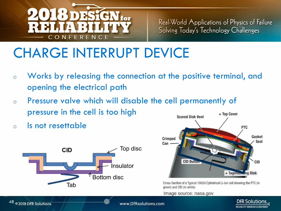
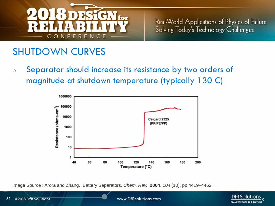
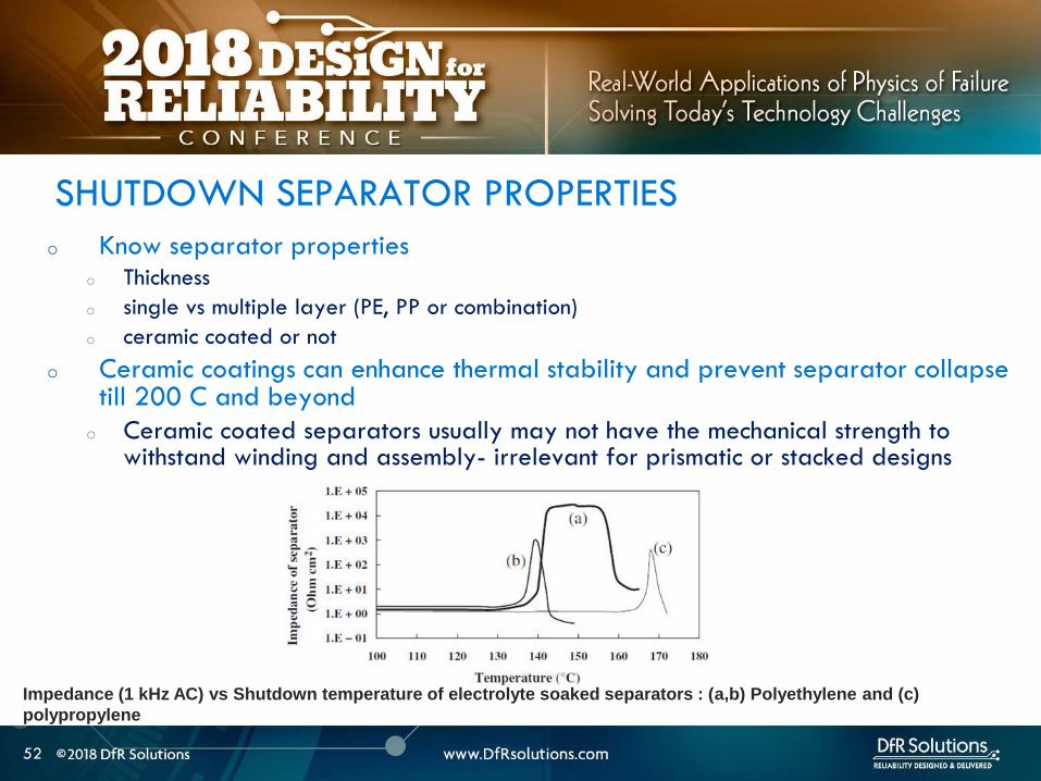
53
BATTERY MANAGEMENT
SYSTEM (BMS) AND
PROTECTION CIRCUITRY
53
54
o Operating outside of specifications
Operating Outside Specifications
Image source Electropaedia
55
o Depends on a number of factors
o State of charge (SOC)
o Ambient temperature
o Cell chemistry
o Cell design
o Most severe thermal runaway occurs in an overcharged state
o Case temperatures can reach 600 C
o High temperatures are driven by exothermic reactions of the electrodes and the electrolyte
Severity of Thermal Runaway
56
o Self heating temperature o Fully charged 18650 cells brought to self heating temperature
(70 to 90 C) in adiabatic environment go into thermal runaway in 2 days
o Fully charged 18650 in adiabatic environment brought to 150 C (with separator melting) will run away in minutes
o UL standard requires fully charged cells to withstand 4 hour storage at 75 C and 10 min storage at 130 C
o IEEE standard requires 1 hour exposure at 130 C
o Overcharge o Charging a 42 V system to 5 V will almost certainly cause
immediate thermal runaway
Thermal Runaway Initiation ndash Some Numbers
57
o EV electric bus caught fire in Shenzhen China during
charging
o BMS Failure
o Without a BMS there is no
safe lithium ion battery
EV Bus Failure
58
o Consist of charger and a battery protection printed circuit board (PCB)
o Also called a battery protection circuit module (PCM)
o Important functions of protection systems include monitoring controlling and terminating charge and discharge as needed
o Failure of protection circuitry to either sense or respond to an out of range condition causes battery failure
ELECTRONIC PROTECTION SYSTEMS
59
o Maintain cells within operating window and prevent cells
from going into
o Over voltage
o Over current
o Over temperature
o Over discharge
o Balance individual cells to enhance overall capacity
o Disconnect batteries in a safe way in emergency situations
o Predict remaining capacity or state of charge
BMS FUNCTIONS
BMS Webinar httpswwwdfrsolutionscombattery-management-systems-and-safety-and-reliability-webinar
60
o Most obvious failure mode is exceeding specified voltage
o Charging a 42 V system to 5 V will almost certainly cause immediate thermal runaway
o Charging at excess currents
o Overcharge effects
o Anode ndash lithium plating rather than intercalation
o Cathode ndashexcess de-intercalation causes crystal structure to collapse and release heat
o Heat and gas release (both Joule heating and parasitic reactions)
o Electrolyte and electrode decomposition
OVER CHARGE - VOLTAGE
61
o Over voltage may be applied to the battery from a defective charger or due to improper monitoring on a single cell
o Slight overcharge (from minor deviations in voltage monitoring) causes capacity loss rather than direct thermal runaway
o Overvoltage protection can be implemented by opening a charge MOSFET or a fuse
o Overcharge protection is so critical that multiple independent circuits are typically used to prevent single points of failure
OVER VOLTAGE
62
o Hazard from over discharge is highly underestimated
o When a cell goes into deep discharge copper ions from the negative electrode current collector dissolve On recharge copper dendrites can form
o Over discharge can also cause breakdown of the SEI layer and gas formation
OVER DISCHARGE
Image Source Rui Guo1 Languang
Lu1 Minggao Ouyanga1 and Xuning
Feng1 Sci Rep 2016
63
How Does a Battery Go into
Deep Discharge
63
64
o Uncontrolled storage without appropriate recharge
procedures
o Mechanically damaged cells (from electronics impinging
on cell)
OVER DISCHARGE SCENARIOS
65
o Three kinds of discharge occur during storage o PCM sleep current and leakage currents
o Battery self discharge
o Manufacturing quality
o Temp
o State of charge
o Device sleep currents
o At 3 V (or other threshold cutoff) load is disconnected although above lsquoconsumption currentsrsquo are active
o At deep discharge cutoff value of 2 V (or other manufacturer specified value) PCM and device sleep currents are turned off but battery self discharge continues
Discharge During Storage
66
o Lithium ion self discharge around 1-2 per month + a
few cent for PCM
o High SOC and temperatures degrade storage life (and
cycle life)
o Rule of thumb ndash 10 C increase in temperature doubles self
discharge rate
o Store at conditions close to 25 C and 40 SOC
Battery Self Discharge
67
o To keep the contamination as low as possible to reduce
leakage current de-ionized water wash should be used
in the board cleaning process
o Verify the board cleanliness to make sure the levels of
contamination is low
o Investigate if humidity is an issue and that conformal
needs to be used
PCM (BMS) Self Discharge
68
o Have a pre-check charging function on batteries where deep discharge cutoff voltage was reached Charger circuit checks if a deeply discharged battery is reaches a threshold value in give time Otherwise considered a lsquodamagedrsquo battery
o Mitigating hazard from copper shunts
o Proper battery storage and recharge procedures
o Minimize PCM leakage currents
o Ensure cell quality
o Prevent cell mechanical damage
Deep Discharge Checklist
69
o Over current can causeo Degradation in cycle life
o Thermal runaway
o Threshold limits for current are functions of both current and time Protection circuit system can use different combinations of time and current to produce a fault Example - high currentshort time or lower currentlong time
o Some faults are recoverable such as when a MOSFET is turned on and others are non-recoverable such as when a fuse is ignited
o Causes of over-current could be a defective charger or due to an internal short
OVER CURRENT PROTECTIONS
70
o A good battery management system will limit charge current and voltage at high and low temperature extremes per Japan Electronics and Information Technology Industries Association (JEITA) guidelines
OVER CURRENT
(60 degC)
CoolCold Warm Hot
(0 degC)
Reduce charging
current andor
voltage
Reduce charging
current andor
voltage
71
o Current limits are incorporated into the protection
circuits located in pack or device
o Circuits monitor current in and out of battery and open up
MOSFET to interrupt current
o Backup protection usually includes a fuse or PTC placed
in series with battery pack
SHORT CIRCUIT PROTECTION
72
BATTERY LIFE DEGRADATION
AND STORAGE
72
73
o Battery life example
o Nominal capacity is 2900 mAh End of life capacity at 80 of initial capacity is 2300 mAh
o Is this data sufficient to give you a life of 500 cycles
BATTERY LIFE AND AGING ISSUES
74
o Calendar aging vs cycle life agingo Insertion or ejection of the Lithium ions into and out of the intercalation
spaces during cycling causes the electrode materials to swell or contract
o Repetitive cycling can weaken the electrode structure reducing its adhesion to the current collector This can lead to reduction in charge capacity
BATTERY LIFE DEGRADATION
75
o Storage degradation high temperature aging causes
growth of the passivating layer
o It consumes lithium and electrolyte and leads to capacity loss
and impedance increase (both capacity and power fade)
Pores can be blocked as a result
o Low rate batteries may not see a big impact
(voltage drop = IR)
BATTERY LIFE DEGRADATION CALENDAR AGING
76
o Have two distinct mechanisms
that impact cell life
o Battery aging tests should
involve high temperature
storage tests
BATTERY LIFE DEGRADATION CALENDAR AGING
Image source Electropaedia
77
o Characterize both reversible and irreversible storage loss
o In this example 25 irreversible and 5 reversible
capacity loss
REVERSIBLE VS IRREVERSIBLE STORAGE LOSS
Assume a = 2900 mAh
d = 70 a = 2030 mAh
e = 95 a = 2700 mAh
a
d
e
78
LITHIUM ION CHEMISTRIES
78
79
o Term Lithium-Ion encompasses many different chemistries
o Anode ndash graphite (Lithium Titanate LTO for very fast charge cells)
o Cathode - Cathodes are lithiated metal oxides or lithiated metal
phosphates
o Lithium Cobalt Oxide (LCO)
o Lithium Iron Phosphate(LFP)
o Nickel Manganese Cobalt (NMC)
o Lithium Manganese Oxide(LMO)
o Cathode chemistry is where you get enhancements in safety
energy and power density
Battery Chemistry
80
o Lithium Cobalt Oxide (LCO) ndash commonly used in consumer electronics
o High energy density
o Low power
o Least safe
o Moderate cycle life
Battery Chemistry
o Lithium Iron Phosphate(LFP) ndashndash automotive power tools UPS e-cigs
o Safest chemistry
o High power density
o Very high cycle life
o Lower voltageLower energy density
o Higher self discharge rate
81
o Nickel Manganese Cobalt (NMC) ndashcommon in tools EV applications
e-cigs ndash usually 13 proportion but customization is possible
o Can be optimized for power or energy
o Good safety
o Good cycle life
Battery Chemistry
o Lithium Manganese Oxide(LiMn2O4) ndashndash power tools EV and hybrid vehicles e-cigs
o Low internal resistancehigh power capability (from Manganese)
o Good safety
o Lower energy ndash blends with NMC are used to enhance energy
82
Battery Chemistry Summary
Chemistry LCO NMC LFP LMO
Nominal Voltage(V) 36-37 36-37 32-32 36-37
Charge Voltage(V) 42 42 35-36 42
Safety Poor Good Highest Good
Cycle Life gt500 gt500 gt1000 gt500
Peak Load current (Best result) 2C
(lt1C)
gt30C
(lt10 C)
gt30C
(lt10 C)
Specific energy (WhKg) 150-250 90-120 100-150
Thermal Runaway Temp (ordmC) 150 210 gt270
Used Since 1991 2003 1999 1996
Designation ICR INR IFR IMR
o Knowing chemistry helps to map out worst case scenario
o For pouch cells look at MSDS
83
o Do not see the word LCO
Battery Chemistry in Current EV Systems
84
ESTIMATING STORED ENERGY
84
85
o Risk assessment
o How much energy and wattage does the battery have
o How fast is the energy released
o Is the product worn on or close to the body
o What is the chemistry
o New product category Are there specific user behaviorsproduct
design interactions that increase the risk and impact of thermal away
o Risk mitigation
o Trust but verify
o Do not trust till you verify
o Map out the worst case
BATTERY RISK ASESSMENT
86
o Stored energy is a combination of electrical and chemical
energy
o Electrical Energy
o Chemical energy may be approximated by using heats of
combustion of various flammable components in cell
STORED ENERGY
87
o Specification
o 37 V
o 296 Wh
o 800 mAh
o Useful information 1 Wh = 36 kJ
o Total stored energy = 296 36 = 1065 kJ
STORED ENERGY PRISMATIC EXAMPLE
88
o Assume 1 to 5 g of electrolyte for small prismatic or pouch cell Assume 05 to 1 g of separator
o Electrolyte solvents are generally organic carbonates such as diethyl carbonate (DEC) ethylene carbonate dimethyl carbonate and ethylmethyl carbonate
o Using the heat of combustion of DEC at 2092 kJg 21 to 105 kJ of energy from electrolyte combustion
o Separator is made of polyethylene polypropylene or combination of the two
o By using polypropylene heat of combustion as an approximation at 4266 kJg 21 to 42 kJ energy for the separator
o Total chemical energy approximation is 42 to 147 kJ
STORED CHEMICAL ENERGY SMALL PRISMATIC
89
o Estimate of total energy released is 52 to 117 kJ
STORED ENERGY SMALL PRISMATIC
Cell Type Energy Low (kJ) High (kJ) Amount (g)
Chemical Energy Combustible
materials Total
42 147
Separator 21 42 05 to 1
Electrolyte 21 105 1 to 5
Electrical (nominal voltage to fully
charged state)
1065 121
Prismatic Total 5265 117
90
o Specification o 37 V
o 962 Wh
o 2600 mAh
o Useful information 1 Wh = 36 kJo Heat of combustion of DEC = 2092 kJg
o Polypropylene heat of combustion = 4266 kJg
o For comparison a 190 g stick of dynamite can release 1 MJ of energy1
STORED ENERGY 18650 EXAMPLE SOLUTION
Cell Type Energy Low (kJ) High (kJ) Amount (g)
Chemical Energy Combustible materials Total 122 23561
Separator 5972 6825 14 to 16
Electrolyte 6236 16736 3 to 8
Electrical (nominal voltage to fully charged
state)
3462 393
18650 Total 157 207
1 httpsenwikipediaorgwikiDynamite
91
Is the 18650 Hazard
Relevant to You
91
92
o Smaller batteries - 20 mAh to 500 mAh
o Energy released is 10- to 100 times lower than the 18650o Smaller capacity batteries release smaller amounts of energy
o 150 -200 mAh batteries generally used for headphone applications such as in illustration
Small Batteries
93
o Calculate total energy released from your cell
o Electrical energy + chemical energy
o Use thermal analysis to estimate temperature rise and
compare against allowable surface temperaturesstandards
Worst Case Analysis
Material Burn Threshold for
contact of 05 s (ordmC)
Bare metal 67-73
Ceramics glass and stone 84-90
Plastics 91-99
Wood 128-155
European standard BS EN 132022000
94
o Potential for burn hazard may be estimated
Skin Burn Temperatures
Effect Description Skin
Temperature
(ordmC)
Pain Tingling hot sensation 44
1st degree burn Superficial injury to outer layer skin
is reddened painful
44-55
2nd degree burn Outer layer is burned through
second layer damaged skin is moist
and reddened with blisters intense
pain
55-60
3rd degree burn All skin layers are damaged 60
95
VENT GAS RISK
95
96
o Vent gases mainly consist of H2 hydrocarbons (also called THC or
total hydrocarbon concentration in figure below) CO2 and CO
o Flammable gases include H2 CO and hydrocarbons
Vent Gas Flammability
Ref 1 US DOTFAA Study Lithium Battery Thermal Runaway Vent Gas Analysis Nov 2016
Major gas species concentration for18650 LiCoO2 cell
97
o When a lithium ion battery vents the gas mixture will mix with surrounding air and may or may not ignite
o The following conditions have to be met for an ignition evento Air fuel mixture is within the Lower Flammability Limit (LFL) and (Upper
Flammability Limit) UFL limits
o Ignition source is present
o The most dangerous materials are those with the lowest flash point and widest flammable ranges
o A hot cell case or hot metal sparks ejected from the cell could create an ignition event if the mixture is within flammability limits
Ignition Risk
98
CHEMICAL SPILL RISK
98
99
o In the absence of a fire potential hazard from a damaged lithium ion battery includes the following
o Release of a electrolyte containing a corrosive salt Electrolyte is extremely corrosive and may cause permanent blindness If ingested through the mouth liver and kidney damage is possible
o Reaction of the electrolyte with waterhumidity may generate hydrofluoric acid which are highly toxic and corrosive to the eyes nose throat and skin
o Release of volatile organics toxic gases such as CO HF
Chemical Spill Risk
Ref Various MSDS sheets
100
o Lithiated carbon in a charged anode the Solid Electrolyte
Interphase (SEI) layer or any free lithium (dendritesplating)
will burst into flames when exposed to moist air
o Reaction of lithium with water produces H2 in an exothermic
reaction
o Significant heat is released in this reaction and this can ignite the H2
Chemical Risk ndash Lithium Ion and Primary Lithium
101
Lithium Ion Life Cycle ndash
Cradle to Grave
101
102
o Cell Manufacturing
o brought to a low to moderate state of charge for shippingstorage
o Transportation
o Warehouse storage
o Pack or device assembly
o OEM device shipment
o Device Usage
o Recycling
LITHIUM ION BATTERY LIFE CYCLE
103
o Almost all failures are related to improper packaging (potential for mechanical damage and external shorts) and shipment procedures
o International Air Transportation Association (IATA) shipment procedures for dangerous goods Cell manufacturers must show proof of UN 383 certification
o 1) Lithium ion batteries (not contained in equipment) shall not be shipped with SOC greater than 30
o 2) Shall pass UN 383 battery of tests
o 3) Shall not be shipped on passenger aircraft
Transportation Procedures
See httpwwwiataorgwhatwedocargodgrDocumentslithium-battery-shipping-guidelinespdf
104
o Small cell shipment exceptions to class 9 dangerous goods classification
o Only Carry-on and Section II are exempt from Class 9 hazardous material
designation
Transportation Procedures
Image source
Battery university
105
o Have procedures in place for safe handling of lithium ion
batteries
o Protection from short circuit high temperature is critical
o Pouch cells must use recessed packaging trays
Storage and Warehouse Handling
106
o Do not single stream recycle lithium ion batteries
o High risk of ignition with surrounding paper and cardboard
o Lithium Ion batteries can be recycled but only at specified
locations Visit httpswwwcall2recycleorglocator
(Rechargeable Battery Recycling Corporation)
o 86 of US and Canadian residents live within 10 miles of
drop-off location
o httpswwwcall2recycleorg for battery recycling resources
Lithium Ion Recycling Procedures
107
o Do not discard as trash
o When collecting batteries make sure they are taped or
insulated
o Recommend drop-off instead
Lithium Ion Recycling Procedures
108
COMPLIANCE TESTING
108
109
o Tests that have the same name under different standards are not always the same
o There are differences in terms of the state of charge aging of the cells and sample sizes and these can have significant differences
o The vendor must state the test standard specify a test description in addition to the name of the test
BATTERY COMPLIANCE TESTING
110
o UNDOT 383 Covers transportation safety testing for all lithium
metal and lithium ion cells and batteries This is mandatory
o UL safety standards
o UL 1642 ndash This standard is used for testing lithium cells Battery level tests
are covered by UL 2054
o UL 2054 (Household and Commercial Batteries) ndash For lithium batteries UL
2054 defers all component cell level testing to UL 1642
o CEIIEC 62133 ndash this standard is voluntary in the US but some
countries specify this standard
BATTERY COMPLIANCE TESTING
111
o IEEE 16251725 ndash These standards are applicable to rechargeable batteries for Multi-cell mobile computing devices and for Cellular phones respectively (CTIA or Wireless Association)
o These standards take the most comprehensive approach to battery testing and emphasize that battery pack safety is a function of a) the individual cells b) the battery pack c) the host device d) power supply accessories e) the user f) the environment
o Both standards require design analysis tools such as FMEA or fault tree analysis They also encompass industry best practices in manufacturing and in the areas of cell pack system and charging accessory design
BATTERY COMPLIANCE TESTING
112
The more you know the better
Parting Thought
Questions
bull Contact Vidyu Challa
vchalladfrsolutionscom
301-640-5834
bull wwwdfrsolutionscom resources page for
battery and other electronic reliability
resources
114
APPENDIX
114
115
Battery Seal Quality
o Moisture ingress through
o Laminate face (extremely low due to metal barrier)
o Interfaces (no metal barrier)
o Terminals (good sealing practices mandatory)
o Compensate through large seal width ( generally 2 mm
min)
o Seal width checks
116
o Flash points for common components of lithium ion battery
electrolytes are below
FLASH POINTS
Ref CRC handbook of chemistry and physics
Electrolyte Component Boiling Point Flash Point
Propylene carbonate (PC) 242degC 135degC
468degF 275degF
Ethylene carbonate (EC) 248degC 145degC
478degF 293degF
Di-Methyl carbonate (DMC) 91degC 18degC
195degF 64degF
Diethyl carbonate (DEC) 126degC 25degC
259degF 77degF
Ethyl methyl carbonate (EMC) 107degC 25degC
225degF 77degF
117
o Flammability limits for vent gases from Li Ion batteries are in
table below
Ref Combustion Flames and Explosion of Gases 2nd Edition Academic Press NY 1961
Compound Lower flammability limit
(fuel volume )
Upper flammability limit
(fuel volume )
Hydrogen 40 750
Carbon monoxide 125 740
Methane 53 150
Ethylene 31 320
Ethane 30 125
Propylene 24 103
C4 hydrocarbons ~ 16-19 ~ 84 ndash 97
C5 hydrocarbons ~ 14-15 ~ 75 ndash 87
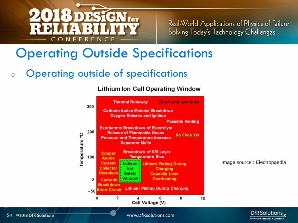
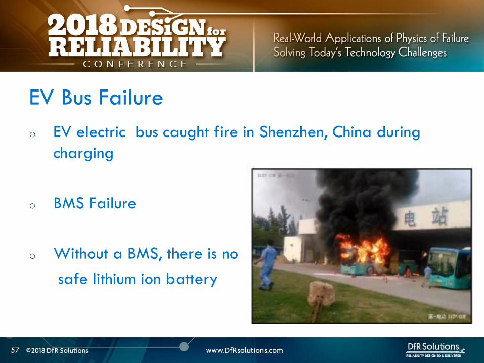