
Hotel Technology Infrastructure - Faculty Websites · This guide was written by Mark Haley and...
44
Infrastructure Technology Hotel Developed by American Hotel & Lodging Association’s Technology Committee Infrastructure Technology Hotel
Transcript of Hotel Technology Infrastructure - Faculty Websites · This guide was written by Mark Haley and...

InfrastructureTechnology
Hotel
Developed by
American Hotel & Lodging Association’s Technology Committee
InfrastructureTechnology
Hotel

Developed by
American Hotel & Lodging Association’s Technology Committee
InfrastructureTechnology
Hotel

This guide was written by Mark Haley and developed by the TechnologyCommittee of the American Hotel & Lodging Association with a grant from the
American Hotel & Lodging Foundation.
Technology CommitteeChairman Robert Bennett, Vice President Systems Property
and ServicesPegasus Solutions, Inc.
Vice Chairman Darrin Pinkham, CHTP Director of TechnologyLoews Hotels at Universal Orlando
AH&LA Staff Liaison Richard J. Jackson, Vice President/CIO American Hotel & Lodging Association
AH&LA Officer Liaison Kirby D. Payne, CHA, AH&LA ChairmanPresident, American Hospitality Management, LLC
Members Carol Beggs, Vice President Technology Sonesta International Hotels Corporation
Kathleen Pearl Brewer, Ph.D., Associate DeanUniversity of Nevada Las Vegas
Brian Garavuso, Chief Technology OfficerMeristar Hotels and Resorts
Mark Haley, CHTP PrincipalThe Prism Partnership
Danny Hudson, Vice President Sales & MarketingNewmarket International, Inc.
Jon Inge, PresidentJon Inge & Associates
Sherry Marek, Vice President of MarketingDatavision Technologies
Joseph Martino, Vice PresidentIDeaS Inc.
Gary Mesich, Vice President IR Business ServicesMarriott International
Richard Siegel, President and PublisherHospitality Upgrade/Siegel Communications Inc.
David Sjolander, Vice President Hotel Information SystemsCarlson Hospitality Corporation
Victor L. Vesnaver, PrincipalV2

Acknowledgements
American Hotel & Lodging Foundation Research and Project Funding Committee
Carol Beggs, Sonesta International Hotels – Editorial ReviewLorraine Dragavon, AH&LA – Project Coordination
Tony Richardson, AH&LA – Printing and Distribution
DesignDrew Banks, Senior Graphic Designer, AH&LA
Disclaimer
This guide is intended only as a general guide concerning Hotel ComputerSystems Infrastructure and does not purport to be, nor should it be used as, acomplete description of Hotel Computer Systems Infrastructure problems orsolutions. Companies should not rely upon this guide for other than generalinformation and should consult their employees and attorneys before imple-menting any suggestions or procedure or using ant forms contained in thisguide. AH&LA does not warrant the accuracy of the guide, the accuracy of com-pleteness of the procedure described in this guide, the effectiveness of such pro-cedures or the effect of any forms contained herein.
©2002 American Hotel & Lodging Association. All rights reserved.

@2002 American Hotel & Lodging Association4

TABLE OF CONTENTSHOTEL TECHNOLOGY INFRASTRUCTURE . . . . . . . . . . . . . . . . . . . . . . . . . . .7
Overview . . . . . . . . . . . . . . . . . . . . . . . . . . . . . . . . . . . . . . . . . . . . . .7
CABLE PLANT CONCEPTS AND PRINCIPLES . . . . . . . . . . . . . . . . . . . . . . . . .11Systems Approach . . . . . . . . . . . . . . . . . . . . . . . . . . . . . . . . . . . . . . .11Key Principles . . . . . . . . . . . . . . . . . . . . . . . . . . . . . . . . . . . . . . . . . .18
TELECOMMUNICATIONS OUTLETS . . . . . . . . . . . . . . . . . . . . . . . . . . . . . . .21
SAMPLE GUESTROOM MARKUP . . . . . . . . . . . . . . . . . . . . . . . . . . . . . . . . .25
HIGH-SPEED INTERNET ACCESS TO GUESTROOMS . . . . . . . . . . . . . . . . . . . .27Overview . . . . . . . . . . . . . . . . . . . . . . . . . . . . . . . . . . . . . . . . . . . . .27Elements of an HSIA Solution . . . . . . . . . . . . . . . . . . . . . . . . . . . . . . . .28
INVECONNECTIONS TO EXTERNAL NETWORKS . . . . . . . . . . . . . . . . . . . . . . .29
MASTER ANTENNA TELEVISION REQUIREMENTS . . . . . . . . . . . . . . . . . . . . .31
WIRELESS . . . . . . . . . . . . . . . . . . . . . . . . . . . . . . . . . . . . . . . . . . . . . .33
SOURCING CABLING CONTRACTORS . . . . . . . . . . . . . . . . . . . . . . . . . . . . .35Overview . . . . . . . . . . . . . . . . . . . . . . . . . . . . . . . . . . . . . . . . . . . . .35 Components of a Cable Plant Request for Proposal . . . . . . . . . . . . . . .36
CABLE PLANT TEST MEASUREMENTS FOR CATEGORY 5e SYSTEM . . . . . . . . . . .39
ADDITIONAL RESOURCES . . . . . . . . . . . . . . . . . . . . . . . . . . . . . . . . . . . .41General Information on Cabling . . . . . . . . . . . . . . . . . . . . . . . . . . . . . .41Trade and Professional Associations . . . . . . . . . . . . . . . . . . . . . . . . .41Manufacturer and Distributor Sites . . . . . . . . . . . . . . . . . . . . . . . . . .42
HOTEL TECHNOLOGY 101
An Introduction to Hotel Systems 5
TABLE OF FIGURESFigure-1: Schematic of Major Cable Plan Components Under TIA/EIA 568 . . . .12
Figure-2: Main Distribution Frame for Voice in a Telecommunications Room . . .13
Figure-3: Intermediate Distribution Frame Supporting Both Fiber-Optic and Copper . . . . . . . . . . . . . . . . . . .14
Figure-4: Properly Terminated TJ-45 Jack Showing Twists Maintained to1/2 Inch of End . . . . . . . . . . . . . . . . . . . . . . . . . . . . . . . . . . .15
Figure-5: Quad RJ-45 Telecommunications Outlet Labeled for Voice and Data . .16
Figure-6: Applying the TIA/EIA 568 Standard in Hotels . . . . . . . . . . . . . . . .17
Figure-7: Patch Panel with Labels May be Used by Housemenas Well as Engineers or IT Staff . . . . . . . . . . . . . . . . . . . . . . . . .19
Figure-8: Sample Guestroom Markup . . . . . . . . . . . . . . . . . . . . . . . . . . . .25
@2002 American Hotel & Lodging Association6

HOTEL TECHNOLOGY INFRASTRUCTURE Welcome to the AH&LA Technology Committee’s Hotel TechnologyInfrastructure Guidebook. The AH&LA Technology Committee is pleased topresent this manual for specifying voice and data requirements in hotels.This Guidebook is one of a series designed by the AH&LA TechnologyCommittee to familiarize hotel owners, operators, and developers with thefundamentals of technology in the hotel environment.
This Guidebook provides an overview of cabling infrastructure requirementsfor a broad range of property-level hotel technology applications. Some ofthese applications include voice and data in guestrooms and public spacesas well as administrative voice and data, including telephone (also known asPrivate Branch Exchange, or PBX), Property Management Systems (PMS),Point of Sale systems (POS), video (free-to-guest, pay-per-view, and interac-tive), locking systems, high-speed Internet access (HSIA), and more. Theintended audience is hotel operators or developers with no particular tech-nology or engineering background. Rather than being a treatise on cableplant engineering, the discussion is organized to answer such questions as“What do I do in my guestrooms about voice communications?” TheAdditional Resources section on page 41 contains a variety of technical andlaymen’s resources for more detailed information, if required.
OverviewThe material is presented in sufficient detail to provide the foundation ofbid specifications for cabling contractors engaged by the hotel operator ordeveloper in a new build or renovation scenario. If the property is installinga new system rather than undergoing renovation, then the principlesdescribed herein still apply and may be implemented on as-needed basis.
HOTEL TECHNOLOGY 101
An Introduction to Hotel Systems 7

1 The four types of communications protocol are analog voice, digital voice, TCP/IP over Ethernet, and RS-232 serial.2 Recognize that these warranties mean that the cable plant will perform in accordance with today’s TIA/EIA 568 standard for 25 years, not that the technology in place in 10 years may not need a different standard.
@2002 American Hotel & Lodging Association8
The property owner or manager seeks three simple things from the cableplant:
That it support the installed systems today, without failures.
That it be a cost-effective installation.
That it be maintainable and upgradeable with the life of the asset.
Most computer systems likely to be installed in a hotel today connect tele-phones, terminals, printers, and hosts via one of four types of communica-tion protocol.1 Using the principles in this Guidebook and some planning,you will be able to support all of these devices through a single wall platewithout rewiring for many years into the future.
The challenge for the hotelier is to define an infrastructure that supports all of these communications methods today and those that may cometomorrow, and to maintain the cable plant in the future. The most effectiveway to meet this challenge is to treat the cable plant as its own system,integral to the building and part of the real asset, much like plumbing orelectricity.
Contrast this structured and systematic approach with the way businessesused to pull cable—dedicated home runs of radically different cable types,each with different termination pin-outs, with device relocations andreplacement dependent on pulling a new cable from the host to the deviceevery time.
This systems approach affords a long-term view (at least 10 years) of thecable plant asset. Many structured cable system installations are sold with10-, 15-, and even 25-year warranties.2 Over this kind of lifecycle, the valueof the maintainable and fully documented cable plant exceeds the initialcost many times over.
The foundation of this systems approach to building infrastructure is knownas the Telecommunications Industry Association/Electronics IndustryAlliance (TIA/EIA) 568 Commercial Building Telecommunications CablingStandard. This is a voluntary standard maintained by the EIA and the TIAunder the auspices of the American National Standards Institute (ANSI).

Since these organizations published the initial standard in 1991, it has wonbroad acceptance and continues to evolve.
Other relevant standards include:
TIA/EIA 569—Cabling Pathways
TIA/EIA 606—Administration
TIA/EIA 607—Grounding & Bonding
National Electric Codes (NEC)
National Fire Protection Association Codes
Construction Specification Institute Division 16—Electrical specifications for construction3
Local building codes
Formal discussion of these other standards is generally beyond the scope of this Guidebook, but many of the concepts presented here are drawn from them.
In the succeeding sections of this Guidebook, we will provide concepts and recommendations for applying the TIA/EIA 568 standard in the hotelindustry for key parts of the hotel, including guestrooms, administrativeareas, and public space. Additional sections will provide detail on coaxialcable support for Master Antenna Television (MATV) systems and alternativesto TIA/EIA 568 for delivering high-speed Internet access (HSIA) into guestrooms. Then we will discuss how to source a qualified cable plantdesigner or installer and provide sources of additional information.
The entire Guidebook equips a hotel owner or developer to build out thecable plant as a value-added component of the hotel that will support theneeds of the building’s users and owners for many years to come.
HOTEL TECHNOLOGY 101
An Introduction to Hotel Systems 9
3 Telecommunications cabling will probably be pulled out of Division 16 and put into its own unit, Division 17, in the near future.

@2002 American Hotel & Lodging Association10

HOTEL TECHNOLOGY 101
An Introduction to Hotel Systems 11
CABLE PLANT CONCEPTS AND PRINCIPLES
Systems ApproachThe cable plant needs to be treated as a building infrastructure system ofits own, much like the electrical, plumbing, or heating, venting, and airconditioning (HVAC) system. This infrastructure perspective means using astructured hierarchy of modular elements that are independent of the appli-cations they support. You will use identical cable plants and often the sameones for analog voice communications, digital voice communications, and abroad range of data applications, including PMS, POS, lock system terminals,and more.
Planning and configuring the cable plant needs to be an integral part of thedesign-build process. Designing the cable plant after construction has pro-gressed beyond a certain point leads to costly rework if the conduit provi-sions prove inadequate. Design the cable plant before you pour concrete.
You may choose to use the modularity and flexibility of the systemsapproach to support a physically separation of computer system devices intoindependent local area networks (LANs). Conversely, you may treat them asterminals on a single LAN supporting all of the applications in the property.Larger properties with more devices and more applications will need moresegmentation.
Architecturally, this approach to cabling is called a “star topology.” It isanalogous to the airlines’ hub-and-spoke route maps, far more efficient thanthe old routes of point-to-point scheduling.
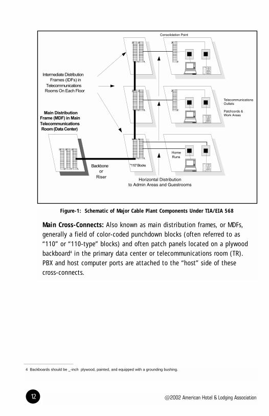
The elements of the cable plant include all of the components required toconnect a telephone or a computer back to the appropriate host device in ahierarchical star topology, as shown in Figure-1.
@2002 American Hotel & Lodging Association12
Figure-1: Schematic of Major Cable Plant Components Under TIA/EIA 568
Main Cross-Connects: Also known as main distribution frames, or MDFs, generally a field of color-coded punchdown blocks (often referred to as“110” or “110-type” blocks) and often patch panels located on a plywoodbackboard4 in the primary data center or telecommunications room (TR). PBX and host computer ports are attached to the “host” side of these cross-connects.
4 Backboards should be _-inch plywood, painted, and equipped with a grounding bushing.

HOTEL TECHNOLOGY 101
An Introduction to Hotel Systems 13
5 Be sure to factor in "missing" 13th floors in assigning TRs under this scheme. 6 Telecommunications grounding and bonding must be part of the building’s grounding infrastructure.
Figure-2: Main Distribution Frame for Voice in aTelecommunicationsRoom
Backbone: Also known as risers. May be either copper or fiber-optic cable.Generally run vertically to TRs on each or staggered floors of the building(one sometimes finds a TR on every third floor,5 supporting the floor above,the floor below, and the floor it is on), or horizontally to different buildingsin a campus environment. The backbone connects the “house” side of theMDFs to the intermediate cross-connects located in the intermediate TRs.
Telecommunications Rooms: TRs should be secured, illuminated, free of dust, environmentally controlled (air conditioned with own thermostat, 50°-75°F), and have adequate 120V AC (120 volts of alternating currentelectrical service) power to support the installed load. TRs must havegrounding points consistent with TIA/EIA 607 and the NEC.6 Do not use TRs as storage or work areas.
The main TR or data center is an “equipment room” under TIA/EIA 568,sharing the characteristics of TRs, but will hold PBXs, servers, and otherequipment as well as wiring and hubs. Ideally, a hotel will have a singlesecured equipment room housing PBXs, servers, in-room entertainmentracks, routers, and the MDF. Do not site the equipment room in a remotelocation. Rather, place it in a central location to avoid distance limitations.

@2002 American Hotel & Lodging Association14
Intermediate Cross-Connects: Also known as intermediate distributionframes, or IDFs. Connect the backbone on the “host” side of the cross-connect to horizontal distribution to telephones, computers, and terminalsin work areas or guestrooms on the “house” side. Consolidation points (CPs)are typically punchdown blocks used as part of the horizontal distribution toa given location such as a guestroom, which is in effect a satellite IDF. IDFsoften require 120V AC power nearby for HSIA switches, MATV amplifiers, andso on.
Figure-3: Intermediate Distribution
Frame Supporting Both Fiber-Optic and Copper Cable
Horizontal Distribution: Usually four twisted pair Category 5e coppercables running from the IDFs to the telecommunications outlets at the work areas. May be bundled to service a satellite distribution frame or patch panel. Fiber is also used for horizontal distribution, especially for long or high-demand routes.

HOTEL TECHNOLOGY 101
An Introduction to Hotel Systems 15
7 One _m equals one micron, a unit of measure also known as micrometer.
Cable: May be made of either copper or fiber optics in a variety of sizes andpair counts. Copper cable is usually rated by “category,” where the higherthe number means higher throughput capacity. The 568 standard specifiesCategory 5e (Cat 5e) for most voice and data applications. Category 6 isexpected to be ratified by the standards bodies in the near future, althoughthere are several Category 6 systems in the market today. Category 7 is inthe U.S. market, but not yet ratified. Category 3 and lower capacity cablesare not recommended.
A crucial element in maintaining the rating of a Cat 5e cable is keeping thetwists in the pairs of conductors intact to within 1/2 inch of each termina-tion and limiting the total length of all patch cables in the channel to lessthan 10 meters. The total length (including all patch cables) of a copperhorizontal channel should be kept less than 100 meters, according to thestandard, with fiber used for longer runs.
Figure-4: Properly Terminated TJ-45 Jack Showing Twists Maintained to 1/2 Inch of End
Fiber-optic cable is usually used for backbone applications, and may be usedfor horizontal distribution as well. Typically, two-fiber multimode cable ofeither 62.5/125 _m7 or 50/125 _m may be used for either horizontal orbackbone applications.

@2002 American Hotel & Lodging Association16
Telecommunications Outlets: Typically wall plates with one or more connectors built into them. Most cable channels terminate in a modularconnector punched down to either the T568A or T568B configuration. RJ-45is the most common connector type used, with the smaller RJ-11 connectorform factor used for some analog voice terminations. MATV telecommunica-tions outlets terminate in an F-Type connector for coaxial cable.
Figure-5: Quad RJ-45 Telecommunications
Outlet labeled for Voice and Data

HOTEL TECHNOLOGY 101
An Introduction to Hotel Systems 17
The T568A8 termination assigns eight color-coded conductors to each of four pairs as follows:
Pin Pair Color1 3 White/Green2 3 Green3 2 White/Orange4 1 Blue5 1 White/Blue6 2 Orange7 4 White/Brown8 4 Brown
The T568B termination uses the same pair and color assignments, switching the positions of pairs 2 and 3.
Pin Pair Color1 2 White/Orange2 2 Orange3 3 White/Green4 1 Blue5 1 White/Blue6 3 Green7 4 White/Brown8 4 Brown
Figure-6: Applying the TIA/EIA 568 Standard in Hotels
TIA/EIA 568 does not tell you how to cable a hotel. It defines in greatdetail what the characteristics of the components defined above should bein any commercial building. We will present the application of the standardin terms of the following assumptions:
There are at least two analog telephone lines per standard guestroom, with provisions for future use of digital telephone instruments.
Data service is provided to the guestrooms, independent of theadministrative network.
Most hotel systems will be resources on a LAN.
The LAN may or may not be segmented by application.
These assumptions may not hold for all properties in all market segments.
8 The U.S. federal government publication NCS, FTR 1090-1997 only recognizes T568A.
@2002 American Hotel & Lodging Association18
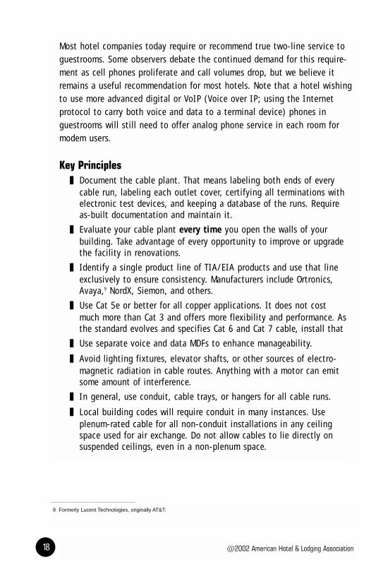
Most hotel companies today require or recommend true two-line service toguestrooms. Some observers debate the continued demand for this require-ment as cell phones proliferate and call volumes drop, but we believe itremains a useful recommendation for most hotels. Note that a hotel wishingto use more advanced digital or VoIP (Voice over IP; using the Internet protocol to carry both voice and data to a terminal device) phones in guestrooms will still need to offer analog phone service in each room formodem users.
Key Principles Document the cable plant. That means labeling both ends of every
cable run, labeling each outlet cover, certifying all terminations withelectronic test devices, and keeping a database of the runs. Requireas-built documentation and maintain it.
Evaluate your cable plant every time you open the walls of yourbuilding. Take advantage of every opportunity to improve or upgradethe facility in renovations.
Identify a single product line of TIA/EIA products and use that lineexclusively to ensure consistency. Manufacturers include Ortronics,Avaya,9 NordX, Siemon, and others.
Use Cat 5e or better for all copper applications. It does not costmuch more than Cat 3 and offers more flexibility and performance. Asthe standard evolves and specifies Cat 6 and Cat 7 cable, install that
Use separate voice and data MDFs to enhance manageability.
Avoid lighting fixtures, elevator shafts, or other sources of electro-magnetic radiation in cable routes. Anything with a motor can emitsome amount of interference.
In general, use conduit, cable trays, or hangers for all cable runs.
Local building codes will require conduit in many instances. Useplenum-rated cable for all non-conduit installations in any ceilingspace used for air exchange. Do not allow cables to lie directly onsuspended ceilings, even in a non-plenum space.
9 Formerly Lucent Technologies, originally AT&T.

HOTEL TECHNOLOGY 101
An Introduction to Hotel Systems 19
Assume growth. Use conduit sufficiently larger than the cable running through it to pull more in the future (40 percent fill maximum). The longer the run or the more bends in it, the larger therequired conduit diameter relative to fill.
Ensure that installers use care in pulling cable, avoiding excessivebending, excessive pull tension (<25#), chafing, or abrading.
Make extensive use of patch panels to facilitate changes and reducethe required skill levels for people making changes.
Figure-7:Patch Panel With Labels May be Used by Housemen as Well asEngineers or IT Staff
Never use flat “silver satin” type patch cords. Use round twisted-paircables labeled Cat 5e.
Do not use splices or bridge taps. Do not split pairs from a Cat 5echannel to support multiple devices.
Ensure that all cable terminations maintain the twists in the cable towithin a 1/2 inch of the termination.
IA/EIA 568 has two different specifications for terminating cables inplugs and jacks, known as T568A and T568B. Either will work, butpick one, use it exclusively, and know which one you use.
@2002 American Hotel & Lodging Association20
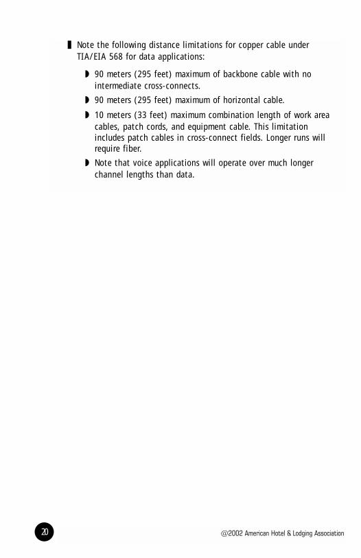
Note the following distance limitations for copper cable underTIA/EIA 568 for data applications:
90 meters (295 feet) maximum of backbone cable with nointermediate cross-connects.
90 meters (295 feet) maximum of horizontal cable.
10 meters (33 feet) maximum combination length of work areacables, patch cords, and equipment cable. This limitationincludes patch cables in cross-connect fields. Longer runs willrequire fiber.
Note that voice applications will operate over much longer channel lengths than data.

HOTEL TECHNOLOGY 101
An Introduction to Hotel Systems 21
TELECOMMUNICATIONS OUTLETS A major decision in any cabling project is determining the number of cableterminations in telecommunications outlets in any given location. The tablebelow is intended to facilitate that decision. Note that, in general, the more telecommunications outlets required in a given location, the more AC electrical power outlets required.
Table of Recommended and Minimum Telecommunications Outlets
Area Assumptions Recommended Minimum CommentsData Center"Equipment Room"in 568 terms
Dedicated datacenter housing PBXand most hotelsystems
Separate voice anddata distributionframes. Data frameequipped with patchpanels.
No dedicateddata service toguestrooms,structured datato administrativelocations.
Some locations mayrequire hubs andswitches distributedin TRs.
Guestrooms
Voice Minimum of twoanalog voice circuitsper guestroom.
If using digital of IPphones, provide ananalog port formodems at deskarea.
25-pair Cat 5ehorizontal cableterminated on apunchdown block inthe guestroom withcross-connect toend points, deskand bathroom forvoice, desk andpossibly televisionfor data.
Two Cat 3horizontal cablesbridged to voiceend points.
CAUTION: Minimumconfiguration will notsupport digital or IPtelephones if bridged.
Rooms with cordlessor digital phonesshould always haveat least one line-powered phone incase of power failure.
Data Minimum of one datacircuit.
As above, dedicatedstrands of Cat 5eterminated on apunchdown blockwith cross-connectto each end point,possibly includingtelevision and mini-bar as well as desk.
Spare drop forfuture applicationsor printers.
Pull two strandsfrom desk area totelevision to supportfuture MATV orHSIA via coaxapplications.
May choose HPNA orsimilar in a retrofit.
MATV Coaxial cablerequired for in-roomentertainmentapplications,including television.
RG-6/U coax toeach television.
RG-6/U coax toeach television
See section 7 belowfor further discussion.Most hotels today usecoaxial cable forMATV applications,but a new build orrenovation shouldanticipate using Cat5e in place of coaxfor some MATVservices in the future.
@2002 American Hotel & Lodging Association22
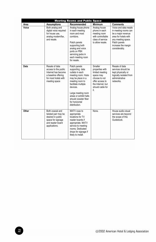
Meeting Rooms and Public Space
Area Assumptions Recommended Minimum CommentsVoice Both analog and
digital voice requiredfor house use,analog modem/fax,and resale.
Analog house phonein each meetingroom and mostcorridors.
Patch panelssupporting bothanalog and voiceports on PBXservicing jacks ineach meeting roomfor resale.
Analog housephone in eachmeeting roomwith controllableclass of serviceto allow resale.
Voice and data resalein meeting rooms canbe a major revenuearea for hotels withany meeting space.Patch panelsincrease the marginconsiderably.
Data Resale of dataaccess to the publicInternet has becomea baseline offeringfor most hotels withmeeting space
Patch panelssupporting dataoutlets in eachmeeting room. Hubsmay be place in ameeting room tofacilitate multipledevices.
Large meeting roomareas or exhibit hallsshould ciosider fiberfor horizontaldistribution.
Smallerproperties withlimited meetingspace maychoose to notoffer access tothe Internet, butshould cable forit.
Resale of dataservices should bekept physically orlogically isolated fromadministrativenetworks.
Other Both coaxial andtwisted pair may bedesired in publicspace for signageand reader boardapplications.
MATV coax toappropriatelocations for TVreader boards ifappropriate. MATVservice to meetingrooms. Dedicateddrops for signage iflikely to install.
None. House audio-visualservices are beyondthe scope of thisGuidebook.

HOTEL TECHNOLOGY 101
An Introduction to Hotel Systems 23
Administrative Locations
Area Assumptions Recommended Minimum CommentsVoice Most administrative
locations will requirevoice and data, withmost voice applica-tions using digitaltelephones.
A single digital voicetelecommunicationsoutlet supportingmultiple voice linesfor most administra-tive users with voicemail.
Analog voiceservice toadministrativelocations.
Data Most administrativeapplications todaycan reside on asingle logical net-work, but someapplications mayrequire dedicatedcabling.
Some franchisorsrequire an "airgap"between any deviceon their reservationsnetwork and anyother network.
Two dataterminations peradministrativelocation.
One datatermination peradministrativelocation.
Administrativenetworks should bekept physically orlogically separatefrom guest networks.
Front desk locationstypically requireadditional termina-tions due to thenumber of deviceslocated there.
Other As required.
Do not forget MATVservice from rooftopor other location ofsatellite receptiondish or antennae.Best to penetrateroof during construc-tion, before sealingand warranty.
As required. Timeclocks, accesscontrol solenoids,cafeteria POS,cafeteria TV, and soon all requireconsideration.

@2002 American Hotel & Lodging Association24
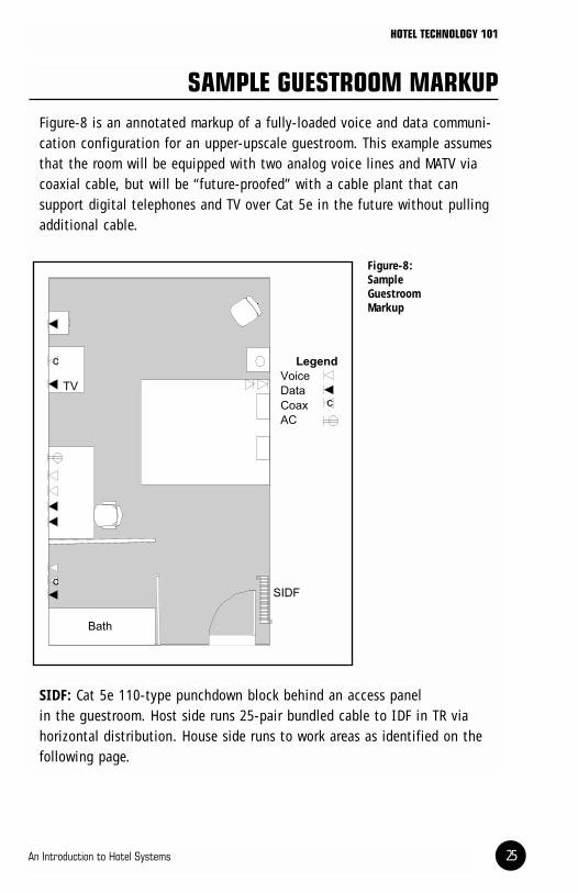
SAMPLE GUESTROOM MARKUPFigure-8 is an annotated markup of a fully-loaded voice and data communi-cation configuration for an upper-upscale guestroom. This example assumesthat the room will be equipped with two analog voice lines and MATV viacoaxial cable, but will be “future-proofed” with a cable plant that can support digital telephones and TV over Cat 5e in the future without pullingadditional cable.
Figure-8:Sample Guestroom Markup
SIDF: Cat 5e 110-type punchdown block behind an access panel in the guestroom. Host side runs 25-pair bundled cable to IDF in TR via horizontal distribution. House side runs to work areas as identified on thefollowing page.
HOTEL TECHNOLOGY 101
An Introduction to Hotel Systems 25

@2002 American Hotel & Lodging Association26
10 Omit unless a luxury hotel installing bathroom televisions. Bathrooms are not a good environment for either televisions or wiringdue to moisture and temperature.
Bedside: Two Cat 5e drops for analog voice applications mounted in aduplex faceplate. Quad 120V AC power.
Desk Area: Two Cat 5e drops for data applications, two for analog voicemounted in a quad faceplate above desk. Quad 120V AC power above desk.
Television(s): Both RG-6/U coax and Cat 5e drops mounted in either oneduplex or two simplex faceplates. Duplex 120V AC power. Pull two strandsfrom TV to desk, leave in wall with 1-meter service loop at each end
Mini-Bar: Cat 5e drop mounted in simplex faceplate. Duplex 120V AC power.
Bathroom: One Cat 5e drop for voice applications, one for MATV and RG-6/Ucoax.10 Duplex 120V AC power.

HIGH-SPEED INTERNET ACCESS TO GUESTROOMS
OverviewAs of this writing, most industry observers believe that travelers will even-tually come to expect HSIA in hotel guestrooms. The same observers sharelittle consensus regarding how this amenity will be funded and delivered.The AH&LA Technology Committee recommends that new builds or majorrenovations implement Cat 5e or better structured cabling systems support-ing data to the guestrooms. Routers, switches, and hubs to support the guestroom broadband service can easily be added or changed by serviceproviders or the hotel itself once the horizontal and backbone distributionis in place.
Some hotels will feel competitive pressures to provide HSIA service in thenear term, without a major renovation facilitating installing Cat 5e horizon-tal distribution to guestrooms. Numerous vendors are in the marketplacewith products that provide in-building distribution over existing Cat 3 cable,coexisting with analog voice traffic. There are multiple variations of howthis is done, but most involve some form of DSL (Digital Subscriber Line)modem mounted in the wall behind the faceplate connected to a DSLAM(Digital Subscriber Line Access Multiplexer), which then is connected to arouter on the public Internet. A property can reduce the total cost per roomof these solutions by using port-sharing devices, reducing the number ofDSLAM ports required. The most common variations found in the hotel mar-ketplace are based on technology endorsed by an industry consortium calledthe HomePNA (Home Phone Networking Alliance, also HPNA).
Cable modems, which use the MATV system to distribute access to theInternet, are another option. While popular in residential applications, cablemodems have had less penetration in the hotel market.
HOTEL TECHNOLOGY 101
An Introduction to Hotel Systems 27

@2002 American Hotel & Lodging Association28
These coexistence tactics for delivering horizontal distribution over existingCat 3 wiring can in fact function, with the notable virtue of rapid and inex-pensive installation. However, performance, consistency, and manageabilityare significantly stronger with a structured Cat 5e implementation for dataonly.
Elements of an HSIA SolutionAny guestroom HSIA solution must address the following elements:
Connection point in the guestroom: Typically an RJ-45 receptacle in a wall-mounted faceplate. Sometimes found on a “puck” or “sled-like” device. Some devices support Universal Serial Bus (USB)interfaces as well as Ethernet from the guest’s laptop.
In-building distribution: As noted above, Cat 5e in a structuredcabling system is the recommended vehicle, with coexistence over Cat 3 voice cable a second choice. Cat 5e solutions will require hubsand switches. Cat 3 coexistence solutions will require some form ofDSL/DSLAM or similar modem and multiplexer.
Subscriber Management Services (SMS): A server, probably locatedin the hotel, that controls user log-on, billing, PMS interface, andreporting. Usually also controls the home page that the guest firstsees. A key function of an SMS application is to “spoof” the user’slaptop into believing that it is attached to whatever network itexpects to be attached to so that no changes are required to theguest’s laptop configuration. The SMS products in the market varywidely in how effectively they handle this requirement.
Connection to the public Internet: Usually via a router supporting aT-1 or fractional T-1 circuit to the Internet. As a general rule, resalenetworks should be kept physically and logically isolated from admin-istrative networks. Many franchisers require an “airgap” separationfrom their reservations networks.
End-user support: Who do guests call when they have a problemconnecting? Very few guest service agents are skilled in trou-bleshooting TCP/IP connections. Typically, the service provider will offer end-user support services via telephone, sometimes for a fee charged to the hotel.

CONNECTIONS TO EXTERNAL NETWORKSAs described above, most hotels have business reasons for connections totwo or more data networks, typically the public Internet and a private network delivering reservations traffic. Some management companies mayuse another private network for accounting or other internal functions aswell. There are also highly effective ways to make a public Internet connection function as a Virtual Private Network (VPN) with both the security of a private network and the cost-effectiveness of the Internet.
These external networks are connected to the hotels in a number of ways.
T-1: A T-1 circuit is a large-capacity digital circuit that can carry 1.5megabits per second (Mbps) of data or up to 23 simultaneous voice conver-sations. A T-1 is a dedicated access connection that is always up, alwaysconnecting two points (typically the hotel and the carrier’s (ATT, Worldcom,Sprint, etc.) nearest point- of-presence (POP). Many hotel companies use T-1 circuits in the hotels with a few channels of frame relay11 data networkand the balance used for voice, so that the voice traffic subsidizes the costof the reservations data network.
Fractional T-1: Uses only a portion of a full T-1 capacity for the data network at a lower cost. The remaining channels are simply not used. Oftenabbreviated as “frac T.”
Integrated Services Digital Network (ISDN): Many T-1 lines are provi-sioned as ISDN circuits, called Primary Rate Interfaces (PRI). Another typeof ISDN service is called Basic Rate Interface (BRI), using two channelsbearing traffic and a signaling channel. An ISDN connection to the publicInternet will yield up to 128k of total bandwidth and may be either dial-upor dedicated. Some mission-critical networks use dial-up ISDN circuits asautomatic fallbacks in case the primary network (typically a dedicated T-1)fails.
HOTEL TECHNOLOGY 101
An Introduction to Hotel Systems 29
11 Frame relay is a very popular type of WAN for data applications, used by most hotel brands for reservations distribution.

@2002 American Hotel & Lodging Association30
12 Don’t forget that modems and fax machines require analog service, not digital. Your digital PBX can present both digital andanalog ports as required.
Digital Subscriber Line (DSL): In addition to using DSL variants for in-building distribution, DSL has become a popular vehicle for cost-effectivededicated Internet connections for residential and small business applica-tions. DSL services are available at various bandwidths, often with a higherdownload capacity than upload capacity (“asymmetric”).
Analog Voice12 Trunks: The basic plain old telephone service (POTS) provided by two wires for every voice circuit, very similar to most residentialtelephone services. Analog POTS trunk service in hotels and other businessis largely being pushed aside by more efficient digital services terminatingon the PBX, but it still has a place both for fallback in case a T-1 fails andfor analog voice lines independent of the hotel PBX.
A large hotel with extensive meeting space and Internet resale will wantone or more T-1s for resale purposes only. Smaller properties might servicetheir resale demand with “frac T” or DSL services.
The data component of any of these external network connections usuallyterminates on a router, which looks at each packet of information anddetermines where it needs to be routed to next. Switching, firewall, andNetwork Address Translation (NAT) functions are often provided by addition-al devices located at the router or built into a multifunction router device.

MASTER ANTENNA TELEVISION REQUIREMENTS
Master Antenna Television (MATV) services are required to deliver broadcast,cable, pay-per-view, and various interactive services to guestrooms.Traditionally, MATV has been delivered by RG-6/U coaxial cable (very similarto the cable TV coax service in your home). More recently, in-room serviceproviders have entered the market delivering pay-per-view, interactive, andInternet services over Cat 5e rather than coax. Typically, these providers willstill require coax to distribute free-to-guest programming.
Today, developers should install both coax and Cat 5e for MATV support in anew build or major renovation as a form of future-proofing. Installing coaxonly to support MATV risks limiting future choices for in-room services.
Use your in-room services vendor for final design and specifications of yourMATV system, particularly for the selection and installation of amplifiers,mixers, and filters. The AH&LA Technology Committee cautions developersagainst allowing the provider to install and own the cable plant, however.While it is often attractive to push the cabling cost back to the vendor, apoorly structured agreement can greatly limit the hotel’s future choices andsubject the cable plant asset to mechanic’s liens or other encumbrances inthe event that the provider does not fulfill its obligations. Better to ownthe MATV cable plants yourself as an asset, built to the specifications of theprovider.
Coaxial cable plants share many similarities to the structured Cat 5e systemsdefined in TIA/EIA 568, with backbone and horizontal distribution. Loop-through designs are not recommended. Riser or backbone distribution generally calls for RG-11/U coaxial cable. Long runs (more than 500 feet)require.500 (or larger) hardline backbone. Horizontal distribution to theguestrooms will generally utilize RG-6/U cable. Use conduit according tolocal building codes.
HOTEL TECHNOLOGY 101
An Introduction to Hotel Systems 31
@2002 American Hotel & Lodging Association32
13 Geosynchronous satellites are over the equator, so Northern Hemisphere locations need a southern line-of-site to "see" thesatellite.
Provide dedicated riser cabling, with spare capacity, from the data center tothe rooftop to support satellite dishes and antennae. This riser should ter-minate in a 4-inch weather-capped conduit in a rooftop location with anunobstructed view of the southern sky.13 It is also wise to install a 3-inchantenna mast during construction.

WIRELESSWireless data communications have attracted a great deal of attention inthe marketplace, with the promise of eliminating a lot of the headachesassociated with cable. They also attract attention for being perceived asinsecure. The most widely-used wireless networking standard at this time isknown as 802.11b or “Wi-Fi.”
Any wireless network requires one or more access points, typically placed ina ceiling or TR, which is then wired back to a router in the equipment room.Therefore, a wireless network still requires a structured cabling system, butless horizontal cable. This can be a real advantage in guestrooms, but itrequires that guests have the cards for their laptops, be prepared to installthem, and accept the perceived security risks. Subscription-based servicescan overcome those issues, but at that point, the guest is a customer of thewireless service provider, not of the hotel.
A successful wireless data installation is dependent on properly positioningand tuning the access points. Proper positioning requires a formal engineer-ing survey using test equipment. Place the access points properly and runhorizontal cable to them, rather than placing access points where the cablehappens to be. Access points generally require 120V AC power.
Other useful wireless data applications in the hotel environment include:
Pool and beach bar areas to support handheld POS applications.
Resale for special events in locations that are not normally cabled(golf courses, parking lots, etc.).
Temporary use during renovations or administrative office relocations.
Another type of wireless opportunity is the ability to lease rooftop space tocellular telephone or other radio system providers for their antennae. Thiscan be a lucrative, all-profit source of cash for essentially no work.
HOTEL TECHNOLOGY 101
An Introduction to Hotel Systems 33

@2002 American Hotel & Lodging Association34

HOTEL TECHNOLOGY 101
An Introduction to Hotel Systems 35
SOURCING CABLING CONTRACTORS
OverviewMost telecom and electrical vendors are familiar with TIA/EIA 568. Theirskill levels in implementing it will vary widely. If you use a full-service PBXservice vendor, you will find that it can provide you most cabling services,it already knows your facility, and it has a business relationship with you.Likewise, your in-room service provider should have comparable skills,knowledge, and relationship. Your responsibility is to ask them for an installation compliant with this Guidebook and TIA/EIA 568 and ensure thatthe installation is tested and documented. Ask them about professional orvendor certifications.
To ensure a fully-compliant cable plant for large or sophisticated installa-tions, especially new builds, look for the RCDD certification. A RegisteredCommunications Distribution Designer certificate indicates that the holderhas demonstrated a broad range of expertise in the detailed design andimplementation of cable plants. The RCDD professional designation requirespassing a formal exam, proof of several years of design experience, and regular recertification. The RCDD designation is awarded by the BuildingIndustry Consulting Service International (BICSI) professional association.BICSI also has a certification program for installers and offers a variety ofeducational opportunities for those pursuing these designations.
Vendors are another source of certification. Most of the manufacturers ofintegrated Cat 5e cable, connectors, and so on offer certification in usingtheir product lines. If a vendor proposes using a given product line, askwhether it is certified in it. Manufacturer’s warranties are typically valid onlyif sold and installed by a certified distributor. Many of the manufacturers’Web sites allow you to search for their distributors by location. SeeAdditional Resources on page 41.
However you source cabling contractors, demand testing and certification inaddition to as-built documentation of the cable plant. Although testing mayseem expensive, it is nothing compared to going back later to do the jobover.

@2002 American Hotel & Lodging Association36
Components of a Cable Plant Request for ProposalWhen you are buying cable plant infrastructure sourcing and installation in a new-build or renovation scenario, the developer, project manager, orgeneral contractor should use a structured bidding process. You shouldinclude the following elements in a Request for Proposal (RFP).
Provide an overall description of the project and the project management.
Provide marked-up samples of the most current available drawings with accompanying narrative describing requirements at the telecommunications outlet level in detail. See Figure-8 on page12 for an example.
Require the following components in the response document:
A statement of qualifications, including RCDD certification of leaddesigner (identified by name). You may verify an individual’s RCDDstatus at the BICSI Web site, http://www.bicsi.org/index.htm.
Identification of what manufacturer’s components will be used and astatement of certification on that product line.
A statement of experience with projects similar in scope and nature,particularly hotels.
A statement of full compliance with TIA/EIA 568, 569, 606, and 607 and all local and national codes that apply (see Figure-1 on page 12).
A narrative describing the backbone media and horizontal distribu-tion proposed to satisfy the telecommunications outlet requirementsfor guestrooms, administrative locations, public space, and BOTH.
Estimated conduit sizes and counts required for riser applications.
Certificates of liability and workmen’s compensation insurance coverage in amounts proportional to the scale of the project.
Compliance with union membership requirements as per the overallproject or local custom.

HOTEL TECHNOLOGY 101
An Introduction to Hotel Systems 37
In the Scope of Work section of the RFP, include the following:
Complete turn-key services, including design, build, source, install,cross-connect, test, certify, and document.
Delivery of as-designed plans to project management before workbegins.
Labeling of all cables at both ends according to a documented andconsistent labeling nomenclature. Labeling of all telecommunicationsoutlet faceplates, patch panels, and distribution frames.
Wire-map and swept frequency testing and certification of theinstalled plant as compliant with the electrical characteristic requirements of TIA/EIA 568. See page 39.
Delivery of as-built plans to project management with the test andcertification results.

@2002 American Hotel & Lodging Association38
HOTEL TECHNOLOGY 101
An Introduction to Hotel Systems 39
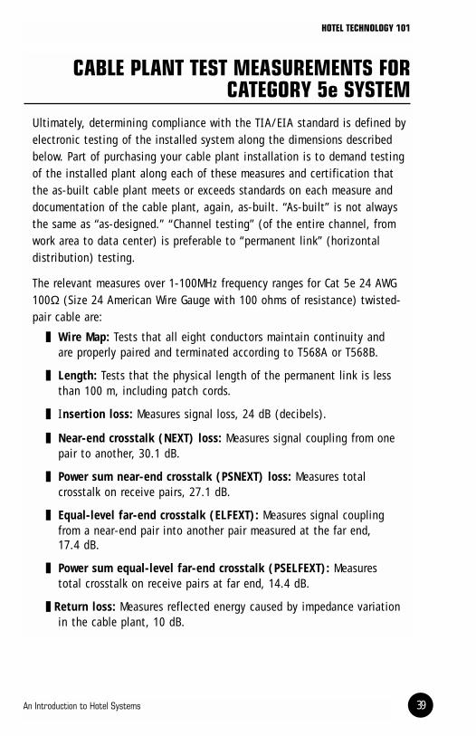
CABLE PLANT TEST MEASUREMENTS FORCATEGORY 5e SYSTEM
Ultimately, determining compliance with the TIA/EIA standard is defined byelectronic testing of the installed system along the dimensions describedbelow. Part of purchasing your cable plant installation is to demand testingof the installed plant along each of these measures and certification thatthe as-built cable plant meets or exceeds standards on each measure anddocumentation of the cable plant, again, as-built. “As-built” is not alwaysthe same as “as-designed.” “Channel testing” (of the entire channel, fromwork area to data center) is preferable to “permanent link” (horizontal distribution) testing.
The relevant measures over 1-100MHz frequency ranges for Cat 5e 24 AWG100Ω (Size 24 American Wire Gauge with 100 ohms of resistance) twisted-pair cable are:
Wire Map: Tests that all eight conductors maintain continuity andare properly paired and terminated according to T568A or T568B.
Length: Tests that the physical length of the permanent link is lessthan 100 m, including patch cords.
Insertion loss: Measures signal loss, 24 dB (decibels).
Near-end crosstalk (NEXT) loss: Measures signal coupling from onepair to another, 30.1 dB.
Power sum near-end crosstalk (PSNEXT) loss: Measures totalcrosstalk on receive pairs, 27.1 dB.
Equal-level far-end crosstalk (ELFEXT): Measures signal couplingfrom a near-end pair into another pair measured at the far end, 17.4 dB.
Power sum equal-level far-end crosstalk (PSELFEXT): Measurestotal crosstalk on receive pairs at far end, 14.4 dB.
Return loss: Measures reflected energy caused by impedance variationin the cable plant, 10 dB.

@2002 American Hotel & Lodging Association40
Propagation delay: Measures time required for a signal to travel fromone end of the channel to the other, 548 ns (nanosecond-1 billionthof a second).
Delay skew: Measures differences in propagation delay from thefastest pair to the slowest, 50 ns.
Recognize that the numeric values shown above are informational.Pass/Fail values on certain measures vary by frequency, test method,temperature, or other variables.
Your cable installer should agree to provide you with test equipment print-outs indicating Pass/Fail for each termination on each of the measuresabove. If it refuses to do this kind of testing, it is not the right contractorfor a full-building or mission-critical job.
Testing is essentially an automated, “push-button” task using an electronicdevice and a skilled operator. The number of measures and complexity ofcalculations may make it seem like a lot of work, but in fact, it is done by asophisticated machine. Typically, wire maps are done with simple devices asterminations are made, and swept frequency channel testing is done laterwith more expensive and sophisticated devices.
ADDITIONAL RESOURCES
General Information on Cablinghttp://www.lodgenet.comDetailed MATV/CATV specifications available for download.
http://www.cableu.netAbsolutely outstanding source for information on copper and fiber cablingin general and TIA/EIA 568. Offers training programs on-line or for sale, aswell as testing products and tools.
http://www.smartwire.com/techcontents.htmVery good site with overview and detail on both TIA/EIA 568 and MATVcabling. Sponsored by a cable distributor.
http://global.ihs.comPurchase the actual standards documents (via download of PDF).
http://www.connectworld.net/Large technical library; “virtual mall” of distributors.
http://www.omeda.com/cim/Site to subscribe to e-mail newsletter Cabling World.
Trade and Professional Associationshttp://www.bicsi.org/index.htmHome page for BICSI, with information on the RCDD professional designa-tion, variations on it, and the Installers certification program.
http://www.tiaonline.orgHome page for the Telecommunications Industry Association, a sponsor ofthe 568 and other standards; markets various trade shows and educationalofferings.
http://www.eia.org/The Electronics Industry Alliance, the co-sponsor of 568.
HOTEL TECHNOLOGY 101
An Introduction to Hotel Systems 41

@2002 American Hotel & Lodging Association42
Manufacturer and Distributor Siteshttp://anixter.com/Full-line distributor.
http://avaya.com/Formerly Lucent Technologies; markets the “Systemax” product line.
http://www.cables-unlimited.com/index.htmlMultiline distributor.
http://www.nordx.com/public/htmen/0_0.aspMarkets the IBDN product line. Spun off from Nortel Networks.
http://ortronics.com/Markets comprehensive structured cabling product line and systems, with a strong certification program.
http://www.panduit.com/Full-line manufacturer.
http://www.siemon.comFull-line manufacturer with strong certification program and educationalofferings.

1201 New York Avenue, NW, #600 • Washington, DC 20005-3931 • www.ahla.com
AHLA/IT002043