HOT GAS DEFROST PIPING DIAGRAMS TABLE OF …1.1. This document reviews standard hot gas defrost...
24
HOT GAS DEFROST PIPING DIAGRAMS Page 1 of 24 ENG00019689 ©2016 Colmac Coil Manufacturing, Inc. HOT GAS DEFROST PIPING DIAGRAMS TABLE OF CONTENTS 1. INTRODUCTION.......................................................................................................................... 2 2. RECIRCULATED SYSTEMS ...................................................................................................... 3 2.1. Figure 1: Bottom Feed, 3-Pipe, Vertical Headers ..................................................................... 3 2.2. Figure 2: Bottom Feed, 3-Pipe, Horizontal Headers ................................................................. 4 2.3. Figure 3: Bottom Feed, 2-Pipe, Vertical Headers ..................................................................... 5 2.4. Figure 4: Bottom Feed, 2-Pipe, Horizontal Headers ................................................................. 6 2.5. Figure 5: Bottom Feed, 4-Pipe, Vertical Headers ..................................................................... 7 2.6. Figure 6: Bottom Feed, 4-Pipe, Horizontal Headers ................................................................. 8 2.7. Figure 7: Top Feed, 3-Pipe, Vertical Headers .......................................................................... 9 2.8. Figure 8: Top Feed, 3-Pipe, Horizontal Headers .................................................................... 10 2.9. Figure 9: Top Feed, 4-Pipe, Vertical Headers ........................................................................ 11 2.10. Figure 10: Top Feed, 4-Pipe, Horizontal Headers ................................................................ 12 3. CONTROLLED PRESSURE RECEIVER (CPR) ....................................................................... 13 3.1. Figure 11: Bottom Feed, 3-Pipe, Vertical Headers ................................................................. 13 3.2. Figure 12: Bottom Feed, 3-Pipe, Horizontal Headers ............................................................. 14 3.3. Figure 13: Bottom Feed, 4-Pipe, Vertical Headers ................................................................. 15 3.4. Figure 14: Bottom Feed, 4-Pipe, Horizontal Headers ............................................................. 16 3.5. Figure 15: Top Feed, 3-Pipe, Vertical Headers ...................................................................... 17 3.6. Figure 16: Top Feed, 3-Pipe, Horizontal Headers .................................................................. 18 3.7. Figure 17: Top Feed, 4-Pipe, Vertical Headers ...................................................................... 19 3.8. Figure 18: Top Feed, 4-Pipe, Horizontal Headers .................................................................. 20 4. DIRECT EXPANSION (DX) ....................................................................................................... 21 4.1. Figure 19: 3-Pipe, Separate Condensate Return, Vertical Header ........................................ 21 4.2. Figure 20: 3-Pipe, Liquid Line Condensate Return, Vertical Headers .................................... 22 5. GRAVITY FLOODED................................................................................................................. 23 5.1. Figure 21: 3-Pipe, Vertical Headers ........................................................................................ 23
Transcript of HOT GAS DEFROST PIPING DIAGRAMS TABLE OF …1.1. This document reviews standard hot gas defrost...

HOT GAS DEFROST PIPING DIAGRAMS
Page 1 of 24 ENG00019689 ©2016 Colmac Coil Manufacturing, Inc.
HOT GAS DEFROST PIPING DIAGRAMS
TABLE OF CONTENTS 1. INTRODUCTION .......................................................................................................................... 2 2. RECIRCULATED SYSTEMS ...................................................................................................... 3 2.1. Figure 1: Bottom Feed, 3-Pipe, Vertical Headers ..................................................................... 3
2.2. Figure 2: Bottom Feed, 3-Pipe, Horizontal Headers ................................................................. 4
2.3. Figure 3: Bottom Feed, 2-Pipe, Vertical Headers ..................................................................... 5
2.4. Figure 4: Bottom Feed, 2-Pipe, Horizontal Headers ................................................................. 6
2.5. Figure 5: Bottom Feed, 4-Pipe, Vertical Headers ..................................................................... 7
2.6. Figure 6: Bottom Feed, 4-Pipe, Horizontal Headers ................................................................. 8
2.7. Figure 7: Top Feed, 3-Pipe, Vertical Headers .......................................................................... 9
2.8. Figure 8: Top Feed, 3-Pipe, Horizontal Headers .................................................................... 10
2.9. Figure 9: Top Feed, 4-Pipe, Vertical Headers ........................................................................ 11
2.10. Figure 10: Top Feed, 4-Pipe, Horizontal Headers ................................................................ 12
3. CONTROLLED PRESSURE RECEIVER (CPR) ....................................................................... 13 3.1. Figure 11: Bottom Feed, 3-Pipe, Vertical Headers ................................................................. 13
3.2. Figure 12: Bottom Feed, 3-Pipe, Horizontal Headers ............................................................. 14
3.3. Figure 13: Bottom Feed, 4-Pipe, Vertical Headers ................................................................. 15
3.4. Figure 14: Bottom Feed, 4-Pipe, Horizontal Headers ............................................................. 16
3.5. Figure 15: Top Feed, 3-Pipe, Vertical Headers ...................................................................... 17
3.6. Figure 16: Top Feed, 3-Pipe, Horizontal Headers .................................................................. 18
3.7. Figure 17: Top Feed, 4-Pipe, Vertical Headers ...................................................................... 19
3.8. Figure 18: Top Feed, 4-Pipe, Horizontal Headers .................................................................. 20
4. DIRECT EXPANSION (DX) ....................................................................................................... 21 4.1. Figure 19: 3-Pipe, Separate Condensate Return, Vertical Header ........................................ 21
4.2. Figure 20: 3-Pipe, Liquid Line Condensate Return, Vertical Headers .................................... 22
5. GRAVITY FLOODED ................................................................................................................. 23 5.1. Figure 21: 3-Pipe, Vertical Headers ........................................................................................ 23
HOT GAS DEFROST PIPING DIAGRAMS
Page 2 of 24 ENG00019689 ©2016 Colmac Coil Manufacturing, Inc.
1. INTRODUCTION 1.1. This document reviews standard hot gas defrost piping diagrams for recirculated, controlled
pressure receiver (CPR), direct expansion and gravity flooded evaporator systems.

HOT GAS DEFROST PIPING DIAGRAMS
Page 3 of 24 ENG00019689 ©2016 Colmac Coil Manufacturing, Inc.
2. RECIRCULATED SYSTEMS 2.1. Figure 1: Bottom Feed, 3-Pipe, Vertical Headers
FIGURE 1
Recirculated Bottom Feed
3-Pipe Hot Gas Defrost Vertical Headers 2-Pass Pan Loop
HOT GAS DEFROST PIPING DIAGRAMS
Page 4 of 24 ENG00019689 ©2016 Colmac Coil Manufacturing, Inc.
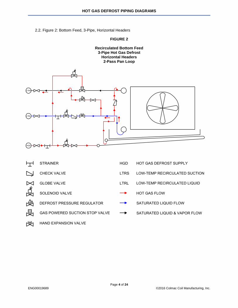
2.2. Figure 2: Bottom Feed, 3-Pipe, Horizontal Headers
FIGURE 2
Recirculated Bottom Feed 3-Pipe Hot Gas Defrost
Horizontal Headers 2-Pass Pan Loop

HOT GAS DEFROST PIPING DIAGRAMS
Page 5 of 24 ENG00019689 ©2016 Colmac Coil Manufacturing, Inc.
2.3. Figure 3: Bottom Feed, 2-Pipe, Vertical Headers
FIGURE 3
Recirculated Bottom Feed 2-Pipe Hot Gas Defrost
Vertical Headers 1-Pass Pan Loop

HOT GAS DEFROST PIPING DIAGRAMS
Page 6 of 24 ENG00019689 ©2016 Colmac Coil Manufacturing, Inc.
2.4. Figure 4: Bottom Feed, 2-Pipe, Horizontal Headers
FIGURE 4
Recirculated Bottom Feed 2-Pipe Hot Gas Defrost
Horizontal Headers 1-Pass Pan Loop

HOT GAS DEFROST PIPING DIAGRAMS
Page 7 of 24 ENG00019689 ©2016 Colmac Coil Manufacturing, Inc.
2.5. Figure 5: Bottom Feed, 4-Pipe, Vertical Headers
FIGURE 5
Recirculated Bottom Feed 4-Pipe Hot Gas Defrost
Vertical Headers 1-Pass Pan Loop

HOT GAS DEFROST PIPING DIAGRAMS
Page 8 of 24 ENG00019689 ©2016 Colmac Coil Manufacturing, Inc.
2.6. Figure 6: Bottom Feed, 4-Pipe, Horizontal Headers
FIGURE 6
Recirculated Bottom Feed 4-Pipe Hot Gas Defrost
Horizontal Headers 1-Pass Pan Loop
HOT GAS DEFROST PIPING DIAGRAMS
Page 9 of 24 ENG00019689 ©2016 Colmac Coil Manufacturing, Inc.
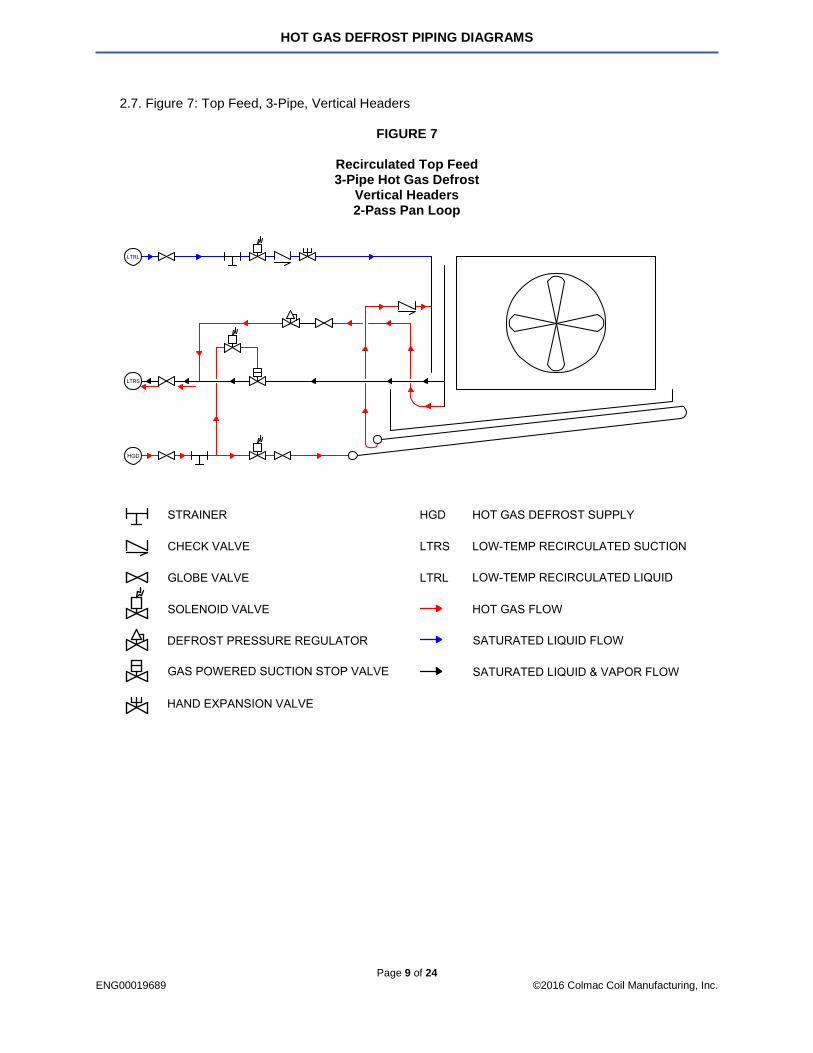
2.7. Figure 7: Top Feed, 3-Pipe, Vertical Headers
FIGURE 7
Recirculated Top Feed 3-Pipe Hot Gas Defrost
Vertical Headers 2-Pass Pan Loop

HOT GAS DEFROST PIPING DIAGRAMS
Page 10 of 24 ENG00019689 ©2016 Colmac Coil Manufacturing, Inc.
2.8. Figure 8: Top Feed, 3-Pipe, Horizontal Headers
FIGURE 8
Recirculated Top Feed 3-Pipe Hot Gas Defrost
Horizontal Headers 2-Pass Pan Loop

HOT GAS DEFROST PIPING DIAGRAMS
Page 11 of 24 ENG00019689 ©2016 Colmac Coil Manufacturing, Inc.
2.9. Figure 9: Top Feed, 4-Pipe, Vertical Headers
FIGURE 9
Recirculated Top Feed 4-Pipe Hot Gas Defrost
Vertical Headers 1-Pass Pan Loop

HOT GAS DEFROST PIPING DIAGRAMS
Page 12 of 24 ENG00019689 ©2016 Colmac Coil Manufacturing, Inc.
2.10. Figure 10: Top Feed, 4-Pipe, Horizontal Headers
FIGURE 10
Recirculated Top Feed 4-Pipe Hot Gas Defrost
Horizontal Headers 1-Pass Pan Loop

HOT GAS DEFROST PIPING DIAGRAMS
Page 13 of 24 ENG00019689 ©2016 Colmac Coil Manufacturing, Inc.
3. CONTROLLED PRESSURE RECEIVER (CPR) 3.1. Figure 11: Bottom Feed, 3-Pipe, Vertical Headers
FIGURE 11
Controlled Pressure Receiver (CPR) Bottom Feed
3-Pipe Hot Gas Defrost Vertical Headers 2-Pass Pan Loop

HOT GAS DEFROST PIPING DIAGRAMS
Page 14 of 24 ENG00019689 ©2016 Colmac Coil Manufacturing, Inc.
3.2. Figure 12: Bottom Feed, 3-Pipe, Horizontal Headers
FIGURE 12
Controlled Pressure Receiver (CPR) Bottom Feed 3-Pipe Hot Gas Defrost
Horizontal Headers 2-Pass Pan Loop

HOT GAS DEFROST PIPING DIAGRAMS
Page 15 of 24 ENG00019689 ©2016 Colmac Coil Manufacturing, Inc.
3.3. Figure 13: Bottom Feed, 4-Pipe, Vertical Headers
FIGURE 13
Controlled Pressure Receiver (CPR) Bottom Feed 4-Pipe Hot Gas Defrost
Vertical Headers 1-Pass Pan Loop

HOT GAS DEFROST PIPING DIAGRAMS
Page 16 of 24 ENG00019689 ©2016 Colmac Coil Manufacturing, Inc.
3.4. Figure 14: Bottom Feed, 4-Pipe, Horizontal Headers
FIGURE 14
Controlled Pressure Receiver (CPR) Bottom Feed 4-Pipe Hot Gas Defrost
Horizontal Headers 1-Pass Pan Loop
HOT GAS DEFROST PIPING DIAGRAMS
Page 17 of 24 ENG00019689 ©2016 Colmac Coil Manufacturing, Inc.
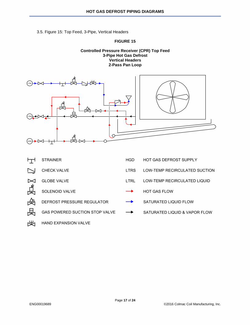
3.5. Figure 15: Top Feed, 3-Pipe, Vertical Headers
FIGURE 15
Controlled Pressure Receiver (CPR) Top Feed 3-Pipe Hot Gas Defrost
Vertical Headers 2-Pass Pan Loop

HOT GAS DEFROST PIPING DIAGRAMS
Page 18 of 24 ENG00019689 ©2016 Colmac Coil Manufacturing, Inc.
3.6. Figure 16: Top Feed, 3-Pipe, Horizontal Headers
FIGURE 16
Controlled Pressure Receiver (CPR) Top Feed 3-Pipe Hot Gas Defrost
Horizontal Headers 2-Pass Pan Loop

HOT GAS DEFROST PIPING DIAGRAMS
Page 19 of 24 ENG00019689 ©2016 Colmac Coil Manufacturing, Inc.
3.7. Figure 17: Top Feed, 4-Pipe, Vertical Headers
FIGURE 17
Controlled Pressure Receiver (CPR) Top Feed 4-Pipe Hot Gas Defrost
Vertical Headers 1-Pass Pan Loop

HOT GAS DEFROST PIPING DIAGRAMS
Page 20 of 24 ENG00019689 ©2016 Colmac Coil Manufacturing, Inc.
3.8. Figure 18: Top Feed, 4-Pipe, Horizontal Headers
FIGURE 18
Controlled Pressure Receiver (CPR) Top Feed 4-Pipe Hot Gas Defrost
Horizontal Headers 1-Pass Pan Loop

HOT GAS DEFROST PIPING DIAGRAMS
Page 21 of 24 ENG00019689 ©2016 Colmac Coil Manufacturing, Inc.
4. DIRECT EXPANSION (DX)
4.1. Figure 19: 3-Pipe, Separate Condensate Return, Vertical Header
FIGURE 19
Direct Expansion (DX) 3-Pipe Hot Gas Defrost
Separate Condensate Return Vertical Header
2-Pass Pan Loop
HOT GAS DEFROST PIPING DIAGRAMS
Page 22 of 24 ENG00019689 ©2016 Colmac Coil Manufacturing, Inc.
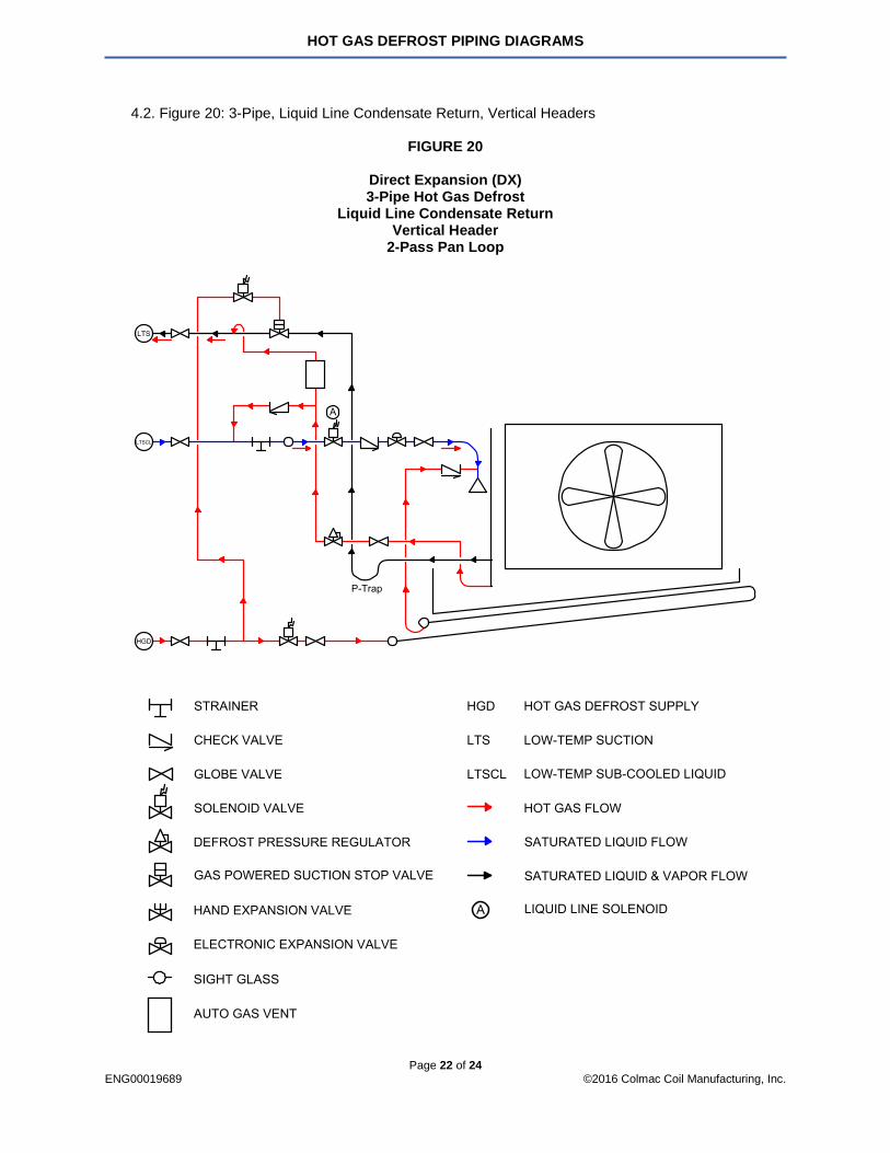
4.2. Figure 20: 3-Pipe, Liquid Line Condensate Return, Vertical Headers
FIGURE 20
Direct Expansion (DX) 3-Pipe Hot Gas Defrost
Liquid Line Condensate Return Vertical Header
2-Pass Pan Loop
HOT GAS DEFROST PIPING DIAGRAMS
Page 23 of 24 ENG00019689 ©2016 Colmac Coil Manufacturing, Inc.
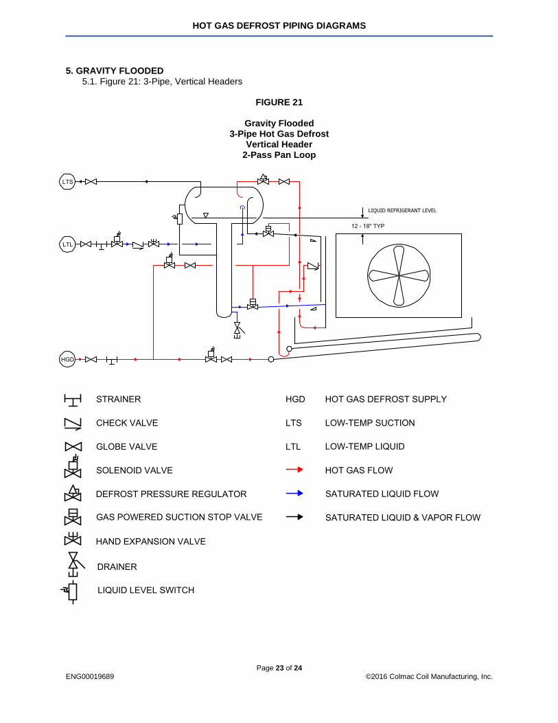
5. GRAVITY FLOODED 5.1. Figure 21: 3-Pipe, Vertical Headers
FIGURE 21
Gravity Flooded
3-Pipe Hot Gas Defrost Vertical Header
2-Pass Pan Loop

HOT GAS DEFROST PIPING DIAGRAMS
Page 24 of 24 ENG00019689 ©2016 Colmac Coil Manufacturing, Inc.
For more information, please contact Colmac Coil Manufacturing, Inc. [email protected] | (800) 845-6778 | (509) 684-2595
P.O. Box 571, Colville, WA. 99114-0571 | www.colmaccoil.com © 2016 Colmac Coil Manufacturing, Inc.