Specifications, Applications, Service Instructions & Parts ...the defrost steps so rapidly that the...
12
Specifications, Applications, Service Instructions & Parts FROST MASTER ® & FROST MASTER ® PLUS DEFROST CONTROLLERS Bulletin F100d JAN 2011 for Industrial/Commercial Evaporator Defrosting FM-71 Defrost Controller INTRODUCTION The Hansen Frost Master ® is an easy-to-use defrost controller for efficient removal of frost accumulation on evaporator coil surfaces. This controller uses simple, reliable solid-state electronics with a precision quartz time clock and time adjusting slide knobs to sequentially operate through logical defrost steps for smooth but complete and effective defrosting. The SPDT relays facilitate flexible connection of solenoid valves and control relays. Defrost mode and step times are easily viewed through the clear cover of the NEMA 4 enclosure. Typically, one controller is used per defrost control valve group. KEY FEATURES User friendly SPDT relays, 10 amp switch rating Entire program always visible Battery back-up Terminals for optional sensor defrost initiation Terminals for optional sensor defrost termination Staggered defrosting is simple 24 hour or 7-day scheduling Precision quartz time clock Remote Initiate only models available APPLICATIONS Designed specifically for defrosting industrial and large commercial refrigeration systems, the Frost Master ® sequences solenoid valves and relays to provide quick and efficient defrosting of evaporator coils. Because of its SPDT relays and time adjustable defrost steps, this controller is suitable for almost every defrost application including: top and bottom feed unit coolers, blast freezer evaporators, and ice makers. Whether the evaporator uses hot gas, electricity, or water to defrost, this controller makes setting or changing defrost periods simple and easy. A very precise quartz time clock facilitates accurate setting of defrost start times. Time clocks include battery back-up in case of short term power failure to avoid any nuisance re-setting of clocks after power interruptions. Demand initiate and coil temperature terminate devices may be directly connected to the Frost Master ® when something other than conventional time-only defrosting is appropriate. The Frost Master ® Plus models offer a built-in temperature terminate feature as well as an additional defrost step, SOFT GAS, which can help minimize pressure shock to the evaporator during defrosting. TABLE OF CONTENTS Specifications, Advantages, Installation ........................ 2,3 Initiation, Termination, Wiring ........................................ 4,5 Frost Master ® Plus (SOFT GAS) ...................................... 6,7 Typical Defrost Applications ........................................... 8,9 Control Valve Selection ............................................... 10,11 Remote Initiate Models, Order Info. ................................ 12
Transcript of Specifications, Applications, Service Instructions & Parts ...the defrost steps so rapidly that the...

Specifications, Applications,Service Instructions & Parts
FROST MASTER® & FROST MASTER® PLUS
DEFROST CONTROLLERS
Bulletin F100dJAN 2011
for Industrial/Commercial Evaporator Defrosting
FM-71 Defrost Controller
INTRODUCTIONThe Hansen Frost Master® is an easy-to-use defrost controller for efficient removal of frost accumulation on evaporator coil surfaces. This controller uses simple, reliable solid-state electronics with a precision quartz time clock and time adjusting slide knobs to sequentially operate through logical defrost steps for smooth but complete and effective defrosting. The SPDT relays facilitate flexible connection of solenoid valves and control relays. Defrost mode and step times are easily viewed through the clear cover of the NEMA 4 enclosure. Typically, one controller is used per defrost control valve group.
KEY FEATURESUser friendly
SPDT relays, 10 amp switch rating
Entire program always visible
Battery back-up
Terminals for optional sensor defrost initiation
Terminals for optional sensor defrost termination
Staggered defrosting is simple
24 hour or 7-day scheduling
Precision quartz time clock
Remote Initiate only models available
APPLICATIONSDesigned specifically for defrosting industrial and large commercial refrigeration systems, the Frost Master® sequences solenoid valves and relays to provide quick and efficient defrosting of evaporator coils. Because of its SPDT relays and time adjustable defrost steps, this controller is suitable for almost every defrost application including: top and bottom feed unit coolers, blast freezer evaporators, and ice makers. Whether the evaporator uses hot gas, electricity, or water to defrost, this controller makes setting or changing defrost periods simple and easy. A very precise quartz time clock facilitates accurate setting of defrost start times. Time clocks include battery back-up in case of short term power failure to avoid any nuisance re-setting of clocks after power interruptions.
Demand initiate and coil temperature terminate devices may be directly connected to the Frost Master® when something other than conventional time-only defrosting is appropriate. The Frost Master® Plus models offer a built-in temperature terminate feature as well as an additional defrost step, SOFT GAS, which can help minimize pressure shock to the evaporator during defrosting.
TABLE OF CONTENTSSpecifications, Advantages, Installation ........................ 2,3Initiation, Termination, Wiring ........................................ 4,5Frost Master® Plus (SOFT GAS) ...................................... 6,7Typical Defrost Applications ........................................... 8,9Control Valve Selection ...............................................10,11Remote Initiate Models, Order Info. ................................ 12

2F100d JAN 2011
MATERIAL SPECIFICATIONSDefrost Steps:
PUMPOUT 0 to 15 minutes
HOT GAS 0 to 45 minutes
EQUALIZE 0 to 5 minutes
FAN DELAY 0 to 5 minutes
(For Plus models, see page 6.)
Relays: SPDT, 10 amp rating each
Defrost Interval:
24 hour clock, 96 settings (15 min. increments)
7-day clock, 84 settings (2 hour increments)
Remote Initiate models, user selectable
Battery Back-Up: 90 hours for quartz time clock
Power: 115V 50/60Hz; 230V 50/60Hz
Terminal Strip: Accepts 14-22 AWG wire sizes
Controller Temperature Range: -20ºF to 120ºF (-29°C to 50°C) ambient
Enclosure: NEMA 4, high impact polycarbonate clear cover, gasketed
Auxiliary ¼” spade terminals for optional defrost initiate or temperature terminate
ADVANTAGESThe control settings are in refrigeration terms, “defrost steps”, which make setting and adjusting the Frost Master® controller simple and easy to understand. The defrost starts with the removal of liquid refrigerant from the evaporator before starting the frost melt period. PUMPOUT (step 1) reduces the load caused by the cold residual liquid refrigerant and exposes more internal surface area to the hot gas. HOT GAS (step 2) introduces the hot gas (or other frost melting medium) to the evaporator for a set period of time or can be temperature terminated. EQUALIZE (step 3) reduces the relatively high pressure inside the newly defrosted evaporator, thus eliminating the sudden, sometimes radical surge in suction pressure when the suction solenoid valve is reopened. FAN DELAY (step 4) freezes the water droplets from the melted frost to the evaporator surface instead of permitting them to blow into the refrigerated space. NORMAL refrigeration resumes by starting the fan motor. Usage of all steps is at the designer’s option and any step may be skipped by setting the defrost step time adjustment to zero.
When used in conjunction with a Demand Initiate Defrost device, this controller can limit the number of defrosts per day or week by not defrosting unless necessary; the time clock can be used to prevent defrost from happening when it would not be advantageous. Temperature terminate contacts are provided to optionally connect a thermostat or other device for minimized defrost time.
The Remote Initiate models (clockless) require only an external, momentary dry contact closure of the initiate terminals from a computer, PLC, push button, etc. to start a defrost cycle. This facilitates great flexibility in various and unusual applications. Frost Master® Plus models are available having an additional defrost step, SOFT GAS, to minimize pressure shock
when hot gas is introduced to evaporator. Also, these models have a built-in temperature terminate feature; see page 6.
INSTALLATIONMount controller, which has a watertight enclosure, in an indoor location away from potential impact or vibration. To fasten, use four screws (0.5” or longer); see installation dimensions below. Do not exceed controller ambient temperature range. Allow space below enclosure for electrical connections. A ½” conduit knockout (0.88” hole) is provided. Any additional holes must be located at the bottom of the enclosure to avoid dust and water damage. Conduit fittings should be of a watertight seal design where applicable. Install 5 amp fuse to protect controller from electrical shorts; see pages 5 and 7.
The Frost Master® is available, less enclosure, with metal mounting plate, for installation in electrical panel or approved outdoor enclosure; see below.
INSTALLATION DIMENSIONSWITH ENCLOSURE
LESS ENCLOSURE WITH METAL MOUNTING PLATE
0.19'' (5 mm) MOUNTING
BOTTOM VIEW
FRONT VIEW
(175 mm)
(157 mm)
(100 mm)
1/2'' CONDUIT KNOCK-OUT
ENCLOSURE BASE
COVER SCREWS (TYPICAL)
CLEAR COVER
3.94''
6.18''
6.89''
(175 mm)
(157 mm)
(29 mm)1.13
HOLES LOCATEDBEHIND COVER SCREWS
6.89''
6.18''
(88 mm)
FMPMODELSONLY
MODELSONLY
FMP
(128 mm)5.05''3.45''
2.95''(75 mm)
(75 mm)2.95''0.34''
0.34''
(9 mm)
(9 mm)
SIDE VIEWFRONT VIEW
0.19'' (5 mm) MOUNTING HOLES4 PLACES
3.00'' (TYPICAL)
6.88''
7.25''
(175 mm)
(184 mm)
(41 mm)
(159 mm)
(76 mm)
(14 mm)
(86 mm)
6.25''
METAL MOUNTING PLATE
1.63'' (TYPICAL)(1 mm)
0.19''(5 mm)
0.03''
0.56''
3.38''

3F100d
JAN 2011
EQUALIZE: 0 to 5 minutes. The EQUALIZE step permits gradual reduction of the pressure inside the evaporator after defrosting to near suction pressure. This is accomplished by either a bleed-down solenoid valve by-passing the suction shut-off valve or by merely allowing the surrounding ambient temperature to cool the evaporator. This step lowers the internal pressure and the likelihood of evaporator, piping and component shock when the suction stop valve is opened. Equalization also reduces the impact of pressure changes upon the suction accumulator. Radical pressure changes cause unnecessary loading and unloading of compressors and also encourage pumps to cavitate. Observing the evaporator pressure gauge during this step may help determine the most appropriate time setting.
FAN DELAY: 0 to 5 minutes. This step resumes normal refrigeration but delays the evaporator fan operation for the set time. This delay enables the remaining water droplets from the melted frost to freeze to the surface of the evaporator, thus preventing them from blowing into the refrigerated space when air flow resumes.
PUMPOUT: 0 to 15 minutes. The PUMPOUT step helps in the removal of liquid refrigerant from the evaporator before defrosting begins. Less liquid means more internal evaporator surface is exposed to entering hot gas. It also reduces the amount of liquid accommodated by the system during defrost.
HOT GAS: 0 to 45 minutes. The HOT GAS step begins the actual melting of the frost accumulation. The amount of time required to remove the frost is dependent on many factors including the following: design of evaporator, quantity of frost accumulation, quality and quantity of hot gas supply, size of valves, etc. A fairly accurate way of setting this time is by observing several defrosts of the evaporator to estimate the amount of time required, possibly by using the Manual Stepping feature of the Frost Master®. Be sure that the HOT GAS step is long enough to entirely remove every portion of the frost. Partial removal of frost is not acceptable because it will tend to increase in mass after each defrost, eventually causing a large frost/ice problem. To help assure complete defrosting where the HOT GAS step duration is desired to be kept to a minimum, a coil clean temperature terminate device is an option. (See TERMINATE, page 4 and 6).
FROST MASTER® DEFROST CONTROLLER
NEMA 4 ENCLOSURE
LIGHTS FOR DEFROST STEPS
DEFROST STEPS TIME ADJUSTMENTS
CLAMP TYPE TERMINALS
GROUNDING SCREW
TIME-OF-DAY AT ARROWHEAD
QUARTZ TIME CLOCK(24 HOUR OR 7-DAY)
TIME CLOCK TABS
“OPTIONAL INITIATE” SPADE TERMINALS
“OPTIONAL TERMINATE” SPADE TERMINALS
DEFROST MODE LIGHT
MANUAL INITIATE & STEPPING BUTTON

4F100d JAN 2011
SETTING DEFROST START TIMESTo set the time-of-day or day-of-the-week (7-day clock) rotate the time clock clockwise until the exact time matches up with the triangle shaped time marker located on the inner dial. To set defrost start times, push the time clock tabs next to the desired times towards the center. Defrosts will begin at each of these times, provided the initiate terminals are closed (for time-only defrost, a factory installed, removable jumper closes these terminals; see DEMAND INITIATE).
Typically, no more than a 1/3 of a plant’s evaporators should be in defrost at one time because an adequate supply of hot gas is required. About 100 psig minimum of hot gas pressure should be available for ammonia or a pressure equivalent to 40ºF (4°C) saturation pressure plus about 30 psi line pressure drop for other refrigerants.
For multiple evaporators with individual defrost controllers, if necessary the defrost start time settings can be staggered by 15 minutes (or multiples thereof) and the 24 hour quartz time clock will maintain this interval accurately. (The 7-day time clock can stagger start times by 2 hours or multiples.) At least one tab must be set away from the center of the time clock between defrosts. Therefore, a ½ hour minimum between defrosts for 24 hour time clocks and a 4 hour minimum for 7-day clocks is required.
SETTING DEFROST STEPSEach defrost step has its own slide knob time adjustment. After determining the proper setting, move each slide knob to a position corresponding to an appropriate amount of time (minutes). Defrost step lights will illuminate during each respective step to inform operator of defrost status. After observing several defrosts, the setting may be easily re-adjusted to more closely match the actual conditions of the application.
DEFROST STEP AND MODE LIGHTSThese lights inform the operator of defrost controller status. A green L .E.D. l ight indicates normal refrigeration. A combination of two red L.E.D. lights indicates the defrost mode and its particular step. If no lights are on, check power to controller.
MANUAL STEPPINGA manual stepping button is provided for initiating and optionally advancing through the defrost steps. This will be helpful when testing electrical operation and connections, as well as manually initiating a defrost during a period of unusual frost accumulation. IMPORTANT: Control devices (solenoid valves, control relays, etc.) can operate while using the manual stepping button. Care should be taken not to advance the defrost steps so rapidly that the evaporator, piping, and other refrigerant components experience sudden or unfavorable conditions.
DEMAND INITIATEThe defrost initiate feature is a normally open (N.O.) pair of ¼” spade terminals (INIT). They must be closed and a time clock tab must trip before a defrost will begin. In other words, initiate for a clock equipped defrost controller will only occur if called for by an initiation device during a clock scheduled defrost period. On the other hand, a “clockless” Remote Initiate Model (FM-01, FM-02, FMP-01) could initiate defrost any time the initiate device closed the terminals. The Frost Master® is supplied with a factory installed jumper wire which closes the initiate terminals. If a remote demand initiate defrost device is to be used for a clock model, simply cut and remove this small, horizontal jumper wire which is soldered between the base of the initiate terminals. Then connect the normally open leads from the initiate device to the initiate spade terminals.
The demand defrost cycle will occur only when the time clock tabs are pushed in and when the initiate device calls for defrost. This prevents defrosts from occurring at inappropriate times. At least one time clock tab must be set away from the center of the time clock between defrost initiate times to “RE-ARM” controller. If there are periods when a demand defrost would not be advantageous (i.e. when loading a room or at the beginning of a work shift), pull the time clock tabs which correspond to these times away from the center of the time clock. A defrost will not be able to start during these times. Should a defrost be requested by the initiate device during this restricted time period, it will not start until the next following pushed-in time clock tab time is reached. This is also ideal in preventing too many or several evaporators in the same room from going into defrost at once. It is feasible to use a computer or similar device in lieu of a frost sensor for demand initiate.
Frost Master® Remote Initiate Models (less any time clock) offer many features suitable for computer initiate, manual push button, and demand defrost devices only; see page 12.
TERMINATEThe defrost terminate feature is a normally open (N.O.) pair of ¼” spade terminals. When there is a closure of these terminals during the HOT GAS step only, the Frost Master® ceases hot gas defrost supply, advances to EQUALIZE and proceeds at the set time intervals through to the other steps. The coil clean terminate device is usually a customer supplied thermostat (temperature switch) set at about 40ºF (4°C) whose sensing bulb is located at the last place on the evaporator coil where frost or ice remains during a defrost. By ending the HOT GAS step as soon as the coil is clean, a quick and efficient defrost occurs. When using a terminate device be sure that the HOT GAS step duration setting is long enough to always permit a complete defrost. If not sure, set to maximum. If the terminate device or thermostat is not actuated, the hot gas supply or other frost melting medium will be terminated by this step time setting. For defrost controller with built-in Temperature Terminate feature and sensor, see Frost Master® Plus models on page 6.

5F100d
JAN 2011
FROST MASTER® RELAY OPERATION
CONTROL VALVE OR RELAY
RELAYDEFROST STEPS NORMAL
REFRIG.PUMPOUT HOT GAS* EQUALIZE FAN DELAY
Liquid Solenoid L
Suction Solenoid S
Hot Gas Solenoid H
Equalize Solenoid E
Fan Motor Relay F
The table above indicates the relay positions during each defrost step and normal refrigeration.
* There is approximately a 5 second delay before the “H” relay switches to its position during this step. This is to give the suction solenoid valve time to close before the hot gas solenoid valve opens.
WIRING DIAGRAMThe wiring diagram below is typical for the bottom feed evaporator shown on page 9. Other wiring schemes are possible to meet system requirements. This wiring diagram is for illustration purposes only and does not show all controls and safety devices. Final control wiring is the responsibility of the system designer. See above table for relay operation.
Relays shown with no power to Frost Master®. See above for relay operation.
= RELAY ENERGIZED
POWERINPUT
RELAY L RELAY SNCNC NO C NO
RELAY HC CNONC CNONC CNONC
RELAY E RELAY F
FAN MOTOR RELAY
HOT GAS SOLENOID VALVE
LIQUID SOLENOID VALVE
NL
EQUALIZE SOLENOID VALVE
CONVENTIONAL SUCTION SOLENOID VALVE
FIELDINSTALLED5 AMP FUSE
INIT
TERM
1 2 3 4 5 6 7 8 9 10 11 12 13 14 15 16 17
OPTIONALDEFROSTINITIATEDEVICE
OPTIONALHOT GASTERMINATEDEVICE
PILOT SOLENOID VALVE TO GAS-POWERED SUCTION STOP VALVE

6F100d JAN 2011
FROST MASTER® PLUS DEFROST CONTROLLER
TERMINATE (Plus MODELS)The defrost terminate feature is built-in to the Frost Master® Plus models. It consists of an accurate, durable temperature sensor and a terminate temperature setting adjustment on the face of the defrost controller. When the terminate temperature is satisfied, the HOT GAS step (or even the SOFT GAS step) will cease and the EQUALIZE step will begin. By ending the HOT GAS step as soon as the coil is clean, a quick and efficient defrost occurs. If the terminate temperature feature is not desired, simply do not connect the temperature sensor and the HOT GAS step will operate on time only.
The terminate temperature adjustment setting range is from 30ºF to 65ºF (-1°C to +18°C); and is usually set about 40ºF (4°C). If the terminate temperature is not reached, the hot gas supply or other frost melting medium will be terminated by the HOT GAS step time duration. Coincidentally, be sure that the HOT GAS step setting duration is long enough to always permit a complete defrost. If unsure, set time duration to maximum.
Locate the terminate temperature sensor at the last place of the evaporator coil where frost or ice remains during a defrost. Fasten sensor to evaporator or piping. Join each of two 6 ft. (183 cm) long sensor wire leads to field sensor wires using the supplied watertight solderless joint connectors. Carefully crimp then heat to seal joint from moisture. Field sensor wire size should be at least 20 AWG (0.5 mm2) and limited to a distance of 500 ft. (152 m). Avoid running wires through evaporator air stream or with high voltage wiring. Connect field sensor wires to terminate temperature sensor quick disconnect plug inside defrost controller enclosure.
TERMINATE TEMPERATURE SENSOR
INTRODUCTIONThis deluxe model, Frost Master® Plus, includes an additional (fifth) defrost step, SOFT GAS, plus a built-in, adjustable, Temperature Terminate feature with clamp-on “defrosted” sensor. Also, the PUMPOUT and EQUALIZE defrost step times are greater than the standard Frost Master®; otherwise, operation is the same.
The SOFT GAS step permits the gradual build-up of pressure inside the evaporator. This is accomplished by opening a small soft (hot) gas solenoid valve prior to opening a primary hot gas solenoid valve during the HOT GAS step. This primes the evaporator for hot gas full flow. The soft gas solenoid valve will remain open throughout the SOFT GAS and HOT GAS steps.
The built-in Temperature Terminate feature enables operator to easily adjust the terminate temperature setting without having to climb a ladder to reach the thermostat (temperature switch) on an evaporator.
TYPICAL APPLICATION
12 1 23
45
67
8
9
10111212
3
45
67
8
910 11
TERMINATE TEMPERATURE SETTING ADJUSTMENT
TERMINATE TEMPERATURE SENSOR QUICK DISCONNECT PLUG
RELAY SG (SOFT GAS) TERMINALS
DEFROST STEPSTIME ADJUSTMENTS
PUMPOUT: 0 TO 45 MINSOFT GAS: 0 TO 5 MINHOT GAS: 0 TO 45 MINEQUALIZE: 0 TO 10 MINFAN DELAY: 0 TO 5 MIN
0.50''
1.25''
0.25''
SIDE VIEW
TOP VIEW
(6 mm)(32 mm)
(13 mm)
0.50''
1.25''
0.25''
SIDE VIEW
TOP VIEW
(6 mm)(32 mm)
(13 mm)

7F100d
JAN 2011
FROST MASTER® PLUS RELAY OPERATION
CONTROL VALVE OR RELAY
RELAYDEFROST STEPS NORMAL
REFRIG.PUMPOUT SOFT GAS* HOT GAS EQUALIZE FAN DELAY
Liquid Solenoid L
Suction Solenoid S
Soft Gas Solenoid SG
Hot Gas Solenoid H
Equalize Solenoid E
Fan Motor Relay F
The table above indicates the relay positions during each defrost step and normal refrigeration.
* There is approximately a 5 second delay before the “SG” relay switches to its position during this step. This is to give the suction solenoid valve time to close before the soft gas solenoid valve opens.
WIRING DIAGRAMThe wiring diagram below is typical for the bottom feed evaporator shown on page 9. Other wiring schemes are possible to meet system requirements. This wiring diagram is for illustration purposes only and does not show all controls and safety devices. Final control wiring is the responsibility of the system designer. See above table for relay operation.
Relays shown with no power to Frost Master® Plus. See above for relay operation.
= RELAY ENERGIZED
POWERINPUT
RELAY L RELAY SNCNC NO C NO
RELAY SGC CNONC CNONC CNONC
RELAY H RELAY E
HOT GAS SOLENOID VALVE
LIQUID SOLENOID VALVE
NL
EQUALIZE SOLENOID VALVE
CONVENTIONAL SUCTION SOLENOID VALVE
FIELDINSTALLED5 AMP FUSE
INIT
1 2 3 4 5 6 7 8 9 10 11 12 13 14 15 16 17
OPTIONALDEFROSTINITIATEDEVICE
HOT GASTERMINATETEMP.SENSOR
201918
RELAY FNC NO C
FAN MOTOR RELAY
SOFT GAS SOLENOID VALVE
PILOT SOLENOID VALVE TO GAS-POWERED SUCTION STOP VALVE

8F100d JAN 2011
INTRODUCTION TO DEFROSTINGWhile the most important component of the defrost system is the controller, it is important to understand the reasoning behind each defrost step as well as other elements which contribute to a successful and efficient defrost sequence. It is obvious that an evaporator in defrost will not have a cooling effect on the refrigerated space, therefore a minimum amount of time in defrost is desirable. However, it is more important to operate a safe and efficient defrost than a speedy one. Defrosting of industrial/large commercial evaporator coil surfaces is predominately accomplished by the use of refrigerant hot (discharge) gas. Other possible methods include: water, air, electric assisted, or combination of several. Even though hot gas defrosting is explained here, the principles are generally the same whatever method is used.
Key elements of a successful defrost system include a reliable hot gas supply, control valves and a defrost controller. The hot gas supply at the evaporator should be free of condensate, sufficient in pressure and quantity to effectively remove ice and frost from the coil surfaces. Valves must be in place to control the flow of hot gas into the evaporator, maintain the pressure inside evaporator above an equivalent saturation pressure of 32ºF (0°C) during defrost, facilitate the removal of refrigerant liquid condensate, limit the entry of hot gas to suction line and minimize pressure shock when normal refrigeration is resumed. The defrost controller should sequence control valves in a manner which minimizes stress to evaporators, piping and compressors. It should stop normal refrigeration and pumpout the evaporator to expose more internal coil surface to the incoming hot gas. Optionally introduce hot gas via a smaller valve to reduce pressure shock to evaporator, then continue by opening a larger hot gas supply valve, but not for an excessive amount of time. Reduce the pressure inside the evaporator before opening main suction valve to avoid suction pressure shock. Start normal refrigeration but delay the fans until remaining water droplets freeze to coil surfaces.
On the next page are typical application examples of hot gas defrosting evaporators with control valves. Although there are many ways to circuit a defrost system, these illustrate some basic methods which apply to most. In general, hot gas is introduced into the top of the evaporator for even heat distribution throughout coil. Refrigerant condensate is removed from the bottom of the evaporator to minimizes the amount of hot gas entering the suction line and to provide a means of oil removal. Typically the defrost relief regulator is set at about 70 psig (5 bar) for ammonia. When a defrost condensate liquid drainer is used, an outlet pressure regulator in the hot gas supply line should be used to limit the internal evaporator pressure. Check valves are installed after the liquid solenoid valve to prevent higher pressure gas from entering the liquid supply line during defrost. Also, check valves are placed between the evaporator and drain pan to keep the pan from accumulating frost during the refrigeration cycle.
SOFT GAS VALVEThe purpose of the soft gas valve is to gradually increase the pressure inside evaporator before introducing full flow hot gas. This reduces the possibility of pressure shock to coil which often has residual liquid from the refrigeration cycle. The soft gas valve should open several minutes prior to the main hot gas valve. The evaporator need not be completely at full hot gas pressure before hot gas valve is opened. Generally, a soft gas valve should be used when the hot gas solenoid valve is 1½” or larger. However, the installation of a soft gas valve could be considered on smaller circuits if the evaporator temperature is below 0°F (-18°C) or it exhibits disturbances upon opening of the hot gas valve.
The ideal soft gas valve size depends on many factors including: evaporator volume, the use of a pumpout step which removes residual refrigerant liquid, the quality and quantity of the hot gas supply pressure, etc. In most cases, a ½” port soft gas valve should be sufficient; such as Hansen Type HS8A. A hand expansion valve (regulator) or globe valve can be installed just after the soft gas valve to fine tune sizing.
EQUALIZE VALVEThe purpose of an equalize valve is to prevent disturbances when opening main valve leading from newly defrosted evaporator to suction pressure. The equalize valve is to be opened several minutes prior to the main valve. The evaporator need not be completely equalized to suction pressure, rather the purpose is to reduce the pressure differential to an acceptable level. In general, it is recommended that an equalize valve be installed on evaporators having 15 tons (53 kW) or greater capacity or a 2½” and larger suction line. However, equalize valves may need to be installed on smaller evaporators depending on degree of disturbance upon opening main suction valve. Many factors can increase the degree of disturbance, including: the pressure dif ference between evaporator and suction, the amount of liquid remaining in evaporator, the size of valves, the complexity of piping, and etc.
The equalize valve size is a function of the evaporator volume and the pressure difference. The valve typically can be 3 or 4 sizes below main valve, but not less than ½” port. A hand expansion valve (regulator) or globe valve can be installed just after the equalize valve to fine tune sizing.

9F100d
JAN 2011
TYPICAL DEFROST APPLICATIONSThese are only examples of possible control valve schemes. As always, they are provided only to assist system designer in applying and selecting valves and controls. Ultimately, designer is responsible for safe and satisfactory operation of any defrost system.
HOT GAS SOLENOID VALVE
SOFT GAS SOLENOID VALVE
HOT GAS LINE
LIQUID SOLENOID VALVE
LIQUID LINEOVERFEED
WITH ELECTRIC SHUT-OFF.STOP VALVE, OR REGULATOROR GAS-POWERED SUCTION SUCTION SOLENOID VALVE,
EQUALIZE SOLENOID VALVE
OVERFEEDSUCTION LINE
FAN
CHECKVALVE
PAN
REGULATORDEFROST RELIEF
HOT GAS LINE
SOFT GAS SOLENOID VALVE
HOT GAS SOLENOID VALVE
CHECKVALVE
PAN
FAN
LIQUID SOLENOID VALVE
WITH ELECTRIC SHUT-OFF.STOP VALVE, OR REGULATOROR GAS-POWERED SUCTION SUCTION SOLENOID VALVE,
FOR EQUALIZINGWITH WIDE OPENING FEATUREDEFROST RELIEF REGULATOR
OVERFEEDLIQUID LINE
SUCTION LINEOVERFEED
BOTTOM FEED EVAPORATOR TOP FEED EVAPORATOR
EVAPORATOR WITH GAS-POWERED SUCTION STOP VALVE
EVAPORATOR WITH DEFROST CONDENSATE LIQUID DRAINER
DEFROST RELIEF
HOT GAS SOLENOID VALVE
SOFT GAS SOLENOID VALVE
HOT GAS LINE
LIQUID LINEOVERFEED
SUCTION LINEOVERFEED
CHECKVALVE
FAN
EQUALIZE SOLENOID VALVE
LIQUID SOLENOID VALVE
STOP VALVEGAS-POWERED SUCTION
PAN
REGULATOR
OVERFEED
SOFT GAS SOLENOID VALVE
HOT GAS SOLENOID VALVE
HOT GAS LINE
LIQUID LINE
OVERFEEDSUCTION LINE
VALVECHECK
FAN
EQUALIZE SOLENOID VALVE
LOADED
DEFROST CONDENSATE
LIQUID SOLENOID VALVE
SUCTION SOLENOID VALVE,OR GAS-POWERED SUCTIONSTOP VALVE.
PAN
OUTLET PRESSUREREGULATOR
CHECK VALVE
LIQUID DRAINER
10F100d JAN 2011
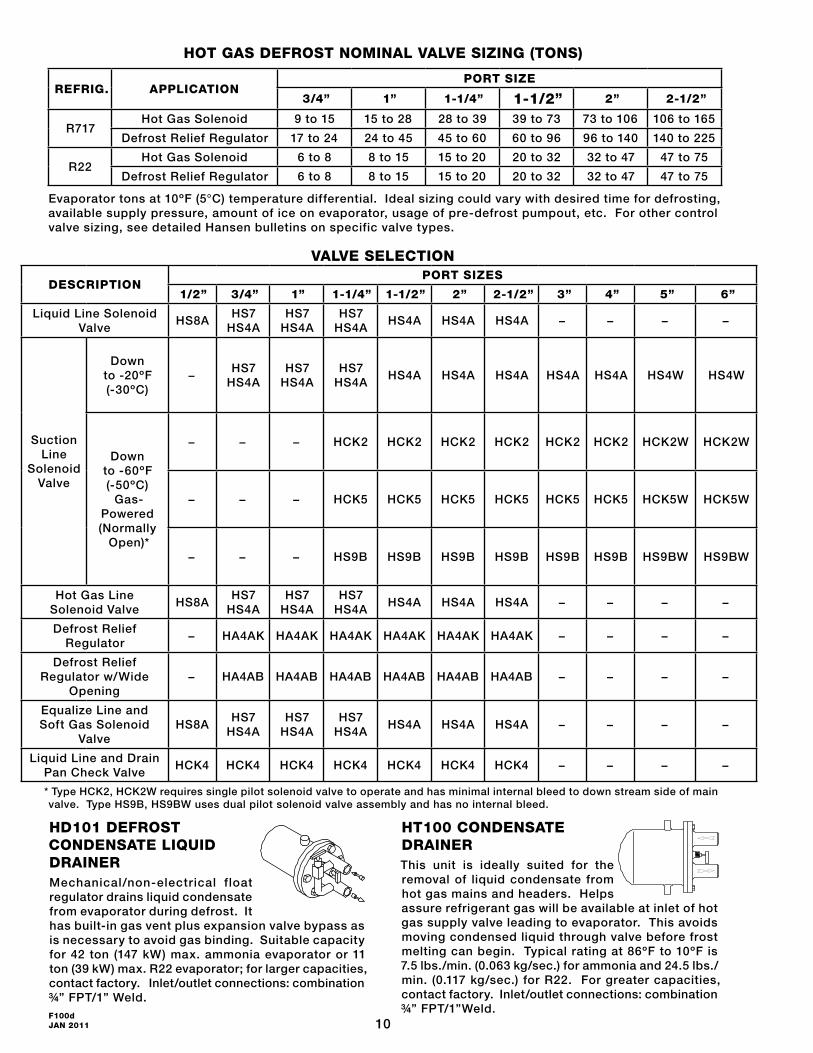
HOT GAS DEFROST NOMINAL VALVE SIZING (TONS)
REFRIG. APPLICATIONPORT SIZE
3/4” 1” 1-1/4” 1-1/2” 2” 2-1/2”
R717Hot Gas Solenoid 9 to 15 15 to 28 28 to 39 39 to 73 73 to 106 106 to 165
Defrost Relief Regulator 17 to 24 24 to 45 45 to 60 60 to 96 96 to 140 140 to 225
R22Hot Gas Solenoid 6 to 8 8 to 15 15 to 20 20 to 32 32 to 47 47 to 75
Defrost Relief Regulator 6 to 8 8 to 15 15 to 20 20 to 32 32 to 47 47 to 75
Evaporator tons at 10ºF (5°C) temperature differential. Ideal sizing could vary with desired time for defrosting, available supply pressure, amount of ice on evaporator, usage of pre-defrost pumpout, etc. For other control valve sizing, see detailed Hansen bulletins on specific valve types.
VALVE SELECTION
* Type HCK2, HCK2W requires single pilot solenoid valve to operate and has minimal internal bleed to down stream side of main valve. Type HS9B, HS9BW uses dual pilot solenoid valve assembly and has no internal bleed.
HT100 CONDENSATE DRAINERThis unit is ideally suited for the removal of liquid condensate from hot gas mains and headers. Helps assure refrigerant gas will be available at inlet of hot gas supply valve leading to evaporator. This avoids moving condensed liquid through valve before frost melting can begin. Typical rating at 86ºF to 10ºF is 7.5 lbs./min. (0.063 kg/sec.) for ammonia and 24.5 lbs./min. (0.117 kg/sec.) for R22. For greater capacities, contact factory. Inlet/outlet connections: combination ¾” FPT/1”Weld.
HD101 DEFROST CONDENSATE LIQUID DRAINERMechanical/non-electrical float regulator drains liquid condensate from evaporator during defrost. It has built-in gas vent plus expansion valve bypass as is necessary to avoid gas binding. Suitable capacity for 42 ton (147 kW) max. ammonia evaporator or 11 ton (39 kW) max. R22 evaporator; for larger capacities, contact factory. Inlet/outlet connections: combination ¾” FPT/1” Weld.
DESCRIPTIONPORT SIZES
1/2” 3/4” 1” 1-1/4” 1-1/2” 2” 2-1/2” 3” 4” 5” 6”
Liquid Line Solenoid Valve
HS8AHS7
HS4AHS7
HS4AHS7
HS4AHS4A HS4A HS4A − − − −
Suction Line
Solenoid Valve
Down to -20ºF (-30ºC)
−HS7
HS4AHS7
HS4AHS7
HS4AHS4A HS4A HS4A HS4A HS4A HS4W HS4W
Down to -60ºF (-50ºC)
Gas-Powered (Normally
Open)*
− − − HCK2 HCK2 HCK2 HCK2 HCK2 HCK2 HCK2W HCK2W
− − − HCK5 HCK5 HCK5 HCK5 HCK5 HCK5 HCK5W HCK5W
− − − HS9B HS9B HS9B HS9B HS9B HS9B HS9BW HS9BW
Hot Gas Line Solenoid Valve
HS8AHS7
HS4AHS7
HS4AHS7
HS4AHS4A HS4A HS4A − − − −
Defrost Relief Regulator
− HA4AK HA4AK HA4AK HA4AK HA4AK HA4AK − − − −
Defrost Relief Regulator w/Wide
Opening− HA4AB HA4AB HA4AB HA4AB HA4AB HA4AB − − − −
Equalize Line and Soft Gas Solenoid
ValveHS8A
HS7 HS4A
HS7 HS4A
HS7 HS4A
HS4A HS4A HS4A − − − −
Liquid Line and Drain Pan Check Valve
HCK4 HCK4 HCK4 HCK4 HCK4 HCK4 HCK4 − − − −

11F100d
JAN 2011
CONTROL VALVESFunction of control valves: Provide hot gas to the coil without liquid slug shocks, close the suction so pressure can build-up, permit condensed refrigerant liquid to exit the coil, control the pressure to a level above freezing equivalent, and after defrost return the coil gradually to plant suction pressure. Control valves are available in ¾” thru 6” (20 mm thru 150 mm) port sizes, unless otherwise stated.
HS8A SOLENOID VALVENormally spring closed, this valve opens wide when energized. Ideally suited for use as a soft gas, liquid or hot gas supply valve. Available in ½” (13 mm) port size. Optional close-coupled strainer (shown) and pilot lights are available.
HS7 SOLENOID VALVENormally spring closed, this valve opens wide when energized. Often used as a liquid supply, hot gas or equalize valve Available in ¾”, 1”, 1¼” (20, 25, 32 mm) port sizes. Optional close-coupled strainer (shown) and pilot lights are available.
HS4A SOLENOID VALVENormally spring closed, this valve opens wide when energized. Can be used as a liquid line supply valve or suction solenoid valve operating at 20F (-30C) or above. Optional close-coupled strainer and pilot lights are available.
HCK4 IN-LINE CHECK VALVEThese in-line check valves (disc type non-return valves) open wide for flow in arrow direction on valve body; promptly close when flow reversals occur. Often they are used on the outlet side of liquid line solenoid valves leading to evaporators to prevent hot gas from entering during defrost. Also they are used between drain pans and evaporators to keep pans from developing frost during refrigeration and after defrost relief regulators leading to intermediate pressure suction lines. They can be mounted in any position and close-coupled to other valves.
HCK2 GAS-POWERED SUCTION STOP VALVE This valve is normally held open via a spring and is gas-powered to close; requires no pressure drop to operate. Requires a single pilot solenoid valve to control. Typically used to close-off evaporators from system suction, especially below -20F (-30C).
HS9B GAS-POWERED SOLENOID VALVEThis valve uses a remote gas or liquid pressure source to close; requires no pressure drop to operate. Dual pilot solenoid valve assembly controls opening and closing of valve without internal bleed to suction. This type of valve is often used to shut-off liquid and gas legs of gravity flooded evaporators .
HA4AD DUAL PRESSURE REGULATORRegulates (evaporator) pressure at a setting when energized, and at a higher setting when de-energized. Used for defrost pressure relief and pressure control.
HA4AK RESEATING RELIEF REGULATORUsed for defrost relief to suction. This control opens when system upstream pressure is above the tagged and sealed set point pressure, and repeatedly reseats after operation.
HA4AS REGULATOR WITH ELECTRIC SHUT-OFFThis control is commonly used for temperature control or defrost. Regulates at its set-for pressure when energized; when de-energized, valve closes tight regardless of pressure setting.
HA4AB REGULATOR WITH ELECTRIC WIDE OPENINGCommonly regulates for defrost or temperature, but opens wide for maximum cooling or equalizing. Regulating at set pressure when de-energized; regulator opens wide when energized.
HA4AL DIFFERENTIAL PRESSURE REGULATORUsed commonly as liquid pump relief. Avoids high discharge pressure from developing when flow becomes restricted due to mult iple evaporators being in defrost at one time. This control modulates to mainta in the set-for dif ference between inlet and outlet pressure.
HA4AO OUTLET PRESSURE REGULATORControls outlet pressure by opening as downstream pressure falls below setting. Used to limit hot gas pressure supply in defrosting evaporators in conjunction with defrost condensate liquid drainers or for regulating pressure in hot gas remains. Can be combined with electric shut-off, dual or wide opening features.
HA4AD
HA4AK
HA4AS
HA4AB
HA4AL
HA4AO
HS8
HS4A
HS7
HCK4
HCK2
HS9B

12F100d JAN 2011
Hansen Technologies Corporation400 Quadrangle Dr, Suite FBolingbrook, Illinois 60440 USATel: 630.325.1565 Fax: 630.325.1572 Toll: 800.426.7368 Email: [email protected] Web: www.hantech.comUSA ∙ Asia ∙ Europe ∙ India ∙ LatinAmerica ∙ MiddleEast© 2011 Hansen Technologies Corporation
CAUTIONHansen Frost Master® defrost controls are only for refrigeration systems. These instructions and related safety precautions must be read completely and understood before selecting, using, or servicing these controls. Only knowledgeable, trained refrigeration mechanics should install, operate, or service these controls. Stated electrical and temperature ranges should not be exceeded. Any wiring and application diagrams provided are for illustration purposes only. The system designer has the final responsibility as to how these defrost controls are connected, set and operated. The designer is also responsible for systems and components being designed to prevent abnormal pressures or velocity impact pressure surges. Where critical temperatures or products are involved, back-up temperature controls or alarms are required. See also Safety Precautions in current List Price Bulletin and Safety Precautions Sheet supplied with product. Escaping refrigerant might cause personal injury, particularly to the eyes and lungs.
SERVICE AND MAINTENANCEThese controllers require practically no service or maintenance. The only field replaceable components are the time clocks (24 hour clock, -A suffix, p/n 67-0007 or -B suffix, p/n 67-0029; or 7 day clock, -A suffix, p/n 67-0009 or -B suffix, p/n 67-0030) for all models and the terminate temperature sensor (p/n 67-0052) for the Frost Master® Plus. To replace clock, disconnect all power to control unit. Remove each of three 5/32” socket cap screws located at corners of clock. Carefully pry clock away with hand. Install new clock by inserting its spade terminals into the clamp connectors located on the controller. Replace screws, restore power, and set time-of-day and defrost start times.
WARRANTYHansen defrost controllers are guaranteed against defective materials or workmanship for 90 days F.O.B. our plant. No consequential damages or field labor is included.
REMOTE INITIATE MODELSRemote Initiate Models FM-01, FM-02 and FMP-01 are supplied less any time clock and horizontal jumper wire. The defrost begins when the initiate spade terminals are momentarily closed. The next defrost will occur as soon as the present defrost is completed and the initiate terminals are opened and then re-closed. This model is especially well suited for use with plant computers, PLC’s, production equipment control relays, push buttons, etc.
TYPICAL SPECIFICATIONS“Defrost controls shall have the ability to pump down evaporator, apply hot gas for frost removal, equalize evaporator pressure, and delay fans. Furthermore, they shall provide connections for optional initiate and terminate defrost devices, be capable of staggering defrosts so as not to allow too many evaporators or evaporators in close proximity to one another from going into defrost at the same time. They shall provide a remote initiate device connection, or 24 hour or 7-day scheduling time clock with battery back-up in case of short term power failure as manufactured by Hansen Technologies Corporation or approved equal.”
ORDERING INFORMATION
CAT. NO. DESCRIPTIONWT. LBS.
FM-11Frost Master® with enclosure 24
hour clock; 115V, 50/60Hz4
FM-71Frost Master® with enclosure
7-day clock; 115v, 50/60Hz4
FM-01Frost Master® with enclosure Remote Initiate; 115V, 50/60Hz
4
FM-12Frost Master® with enclosure 24
hour clock; 230V, 50/60Hz4
FM-72Frost Master® with enclosure
7-day clock; 230V, 50/60Hz4
FM-02Frost Master® with enclosure Remote Initiate; 230V, 50/60Hz
4
For any of above Frost Master® less enclosure with metal mounting plate, add “L” suffix to catalog number; Example: FM-11L.
TO ORDER: Specify Catalog Number.
FROST MASTER® PLUS
CAT. NO.
DESCRIPTIONWT. LBS.
FMP-11Frost Master® Plus
with enclosure, 24 hour clock; 115V, 50/60Hz
4
FMP-71Frost Master® Plus
with enclosure, 7-day clock; 115V, 50/60Hz
4
FMP-01Frost Master® Plus
with enclosure, Remote Initiate; 115V, 50/60Hz
4
REMOTE INITIATE MODEL: FM-01