
Hostel New
88
CHAPTER 1 INTRODUCTION 1.1 PROBLEM DEFINITION: The project “HOSTEL MANAGEMENT” aims at the automation of the records in a hos tel . This red uces the corruptio n and provid es transpare ncy over the maintenance of a hostel. This project also makes the regular tasks such as accessing details, bill payments, etc.., as simpler than before. The following are the main facilities offered by the system: Generating reports of all available students, employees in the hostel. Addition of new student (employee) into hostel. Monthly bill calculations. Allocation, change and vacating the room of a student. Modification of details of a student, employee. Accounts maintenance. Permissions list maintenance. Infrastructure maintenance. Medicines list. 1.2 EXISTING SYSTEM: The information about the student details and the account transactions are maintained manually and there is no secu rity for data being preserved. There is chance of 1
-
Upload
hemamareedu -
Category
Documents
-
view
224 -
download
0
Transcript of Hostel New
8/3/2019 Hostel New
http://slidepdf.com/reader/full/hostel-new 1/88
CHAPTER 1
INTRODUCTION
1.1 PROBLEM DEFINITION:
The project “HOSTEL MANAGEMENT” aims at the automation of the
records in a hostel. This reduces the corruption and provides transparency over the
maintenance of a hostel. This project also makes the regular tasks such as accessing
details, bill payments, etc.., as simpler than before.
The following are the main facilities offered by the system:
Generating reports of all available students, employees in the hostel.
Addition of new student (employee) into hostel.
Monthly bill calculations.
Allocation, change and vacating the room of a student.
Modification of details of a student, employee.
Accounts maintenance.
Permissions list maintenance.
Infrastructure maintenance.
Medicines list.
1.2 EXISTING SYSTEM:
The information about the student details and the account transactions are
maintained manually and there is no security for data being preserved. There is chance of
1
8/3/2019 Hostel New
http://slidepdf.com/reader/full/hostel-new 2/88
modifying the existing information without any authentication. Manual work is more and
very time consuming and involves bugs depending on the status of the person.
1.2.1 DEMERITS OF EXISTING SYSTEM:
∝ Existing system consists of redundant data.
∝ There are more chances for bugs in existing system.
∝ Information retrieval is difficult.
∝ Existing system is very difficult to maintain.
∝ The existing system doesn’t support for authenticated modification of data.
1.3 PROPOSED SYSYTEM:
In this system we are automating all the manual work for faster access of
data. We are utilizing the latest technology by making access simpler. It involves the
automation in the folloeing modules.
Student
Employee
Permissions
Accounts
Monthly bills
Infrastructure
Medicines
1.3.1 MERITS OF AUTOMATION:
Redundancy of the data is much more reduced.
2
8/3/2019 Hostel New
http://slidepdf.com/reader/full/hostel-new 3/88
Fastness in getting the details.
Efficient and effective.
Information retrieval is fast.
Authenticated modification of data is allowed.
1.4 SELECTION OF S/W & HARDWARE STRUCTURE
1.4.1 SOFTWARE REQUIREMENTS:
• Operating system : WINDOWS XP or RED HAT or LINUX
• Connectivity : JAVA SERVLETS
• Data base : ORACLE 9i or 10g.
• Webbrowser : MOZILLA or IE
• Front end : HTML
1.4.2 HARDWARE REQUIREMENTS:
• Processor : PENTIUM-IV & above.
• RAM : 256MB & above.
• Hard Disk : 20GB & above.
• Monitor
1.5 SYSTEM REQUIREMENT SPECIFICATION:
A System Requirements Specification (SRS) - a requirements
specification for a software system - is a complete description of the behavior of a system
3
8/3/2019 Hostel New
http://slidepdf.com/reader/full/hostel-new 4/88
to be developed. It includes a set of use cases that describe all the interactions the users
will have with the software. Use cases are also known as functional requirements. In
addition to use cases, the SRS also contains non-functional (or supplementary)
requirements. Non-functional requirements are requirements which impose constraints on
the design or implementation (such as performance engineering requirements, quality
standards, or design constraints).
1.5.1 FUNCTIONAL REQUIREMENTS:
In software engineering, a functional requirement defines a function of
a software system or its component. A function is described as a set of inputs, the
behavior, and outputs (see also software).
Functional requirements may be calculations, technical details, data
manipulation and processing and other specific functionality that define what a system is
supposed to accomplish. Behavioral requirements describing all the cases where the
system uses the functional requirements are captured in use cases. Generally, functional
requirements are expressed in the form “system shall do <requirement>”. The plan for
implementing functional requirements is detailed in the system design. In requirements
engineering, functional requirements specify particular results of a system. Functional
requirements drive the application architecture of a system. A requirements analyst
generates use cases after gathering and validating a set of functional requirements. The
hierarchy of functional requirements is: user/stakeholder request -> feature -> use case -> business rule. Each use case illustrates behavioral scenarios through one or more
functional requirements. Often, though, an analyst will begin by eliciting a set of use
cases, from which the analyst can derive the functional requirements that must be
4
8/3/2019 Hostel New
http://slidepdf.com/reader/full/hostel-new 5/88
implemented to allow a user to perform each use case. The use cases for this project are
briefly described under SYSTEM ANALYSIS SECTION.
The precondition for the administrator is administrator has to login and access the
homepage.After accessing the page administrator can choose various menu like new
student enrollment,room allocations,monthlybill,medicines,infrastructure etc.The alternate
path for administrator is logging into the home page
1.5.2 NON-FUNCTIONAL REQUIREMENTS:
In systems engineering and requirements engineering, a non-functional
requirement is a requirement that specifies criteria that can be used to judge the operation
of a system, rather than specific behaviors. This should be contrasted with functional
requirements that define specific behavior or functions. The plan for implementing
functional requirements is detailed in the system design. The plan for implementing non-
functional requirements is detailed in the system architecture.
In general, functional requirements define what a system is supposed to do
whereas non-functional requirements define how a system is supposed to be. Functional
requirements are usually in the form of "system shall <do requirement>", while non-
functional requirements are "system shall be <requirement>".
Non-functional requirements are often called qualities of a system. Other terms for
non-functional requirements are "constraints", "quality attributes", "quality goals",
"quality of service requirements" and "non-behavioral requirements". Qualities, that is,
non-functional requirements, can be divided into two main categories:
5
8/3/2019 Hostel New
http://slidepdf.com/reader/full/hostel-new 6/88
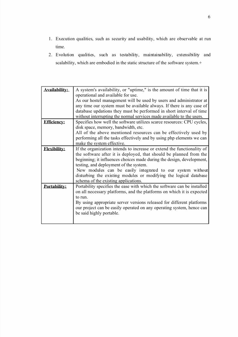
1. Execution qualities, such as security and usability, which are observable at run
time.
2. Evolution qualities, such as testability, maintainability, extensibility and
scalability, which are embodied in the static structure of the software system.+
Availability: A system's availability, or "uptime," is the amount of time that it isoperational and available for use.As our hostel management will be used by users and administrator atany time our system must be available always. If there is any case of database updations they must be performed in short interval of time
without interrupting the normal services made available to the users.Efficiency: Specifies how well the software utilizes scarce resources: CPU cycles,disk space, memory, bandwidth, etc.All of the above mentioned resources can be effectively used by performing all the tasks effectively and by using php elements we canmake the system effective.
Flexibility: If the organization intends to increase or extend the functionality of the software after it is deployed, that should be planned from the beginning; it influences choices made during the design, development,testing, and deployment of the system. New modules can be easily integrated to our system without
disturbing the existing modules or modifying the logical databaseschema of the existing applications.
Portability: Portability specifies the ease with which the software can be installedon all necessary platforms, and the platforms on which it is expectedto run.By using appropriate server versions released for different platformsour project can be easily operated on any operating system, hence can be said highly portable.
6
8/3/2019 Hostel New
http://slidepdf.com/reader/full/hostel-new 7/88
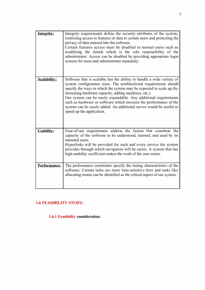
Integrity: Integrity requirements define the security attributes of the system,restricting access to features or data to certain users and protecting the privacy of data entered into the software.Certain features access must be disabled to normal users such as
modifying the details which is the sole responsibility of theadministrator. Access can be disabled by providing appropriate loginscreens for users and administrator separately.
Scalability: Software that is scalable has the ability to handle a wide variety of system configuration sizes. The nonfunctional requirements shouldspecify the ways in which the system may be expected to scale up (byincreasing hardware capacity, adding machines, etc.).Our system can be easily expandable. Any additional requirements
such as hardware or software which increase the performance of thesystem can be easily added. An additional server would be useful tospeed up the application.
Usability: Ease-of-use requirements address the factors that constitute thecapacity of the software to be understood, learned, and used by itsintended users.Hyperlinks will be provided for each and every service the system provides through which navigation will be easier. A system that has
high usability coefficient makes the work of the user easier.
Performance: The performance constraints specify the timing characteristics of thesoftware. Certain tasks are more time-sensitive here and tasks likeallocating rooms can be identified as the critical aspect of our system.
1.6 FEASIBILITY STUDY:
1.6.1 Feasibility consideration:
7

8/3/2019 Hostel New
http://slidepdf.com/reader/full/hostel-new 8/88
8/3/2019 Hostel New
http://slidepdf.com/reader/full/hostel-new 9/88
Use-oriented techniques are widely used in software requirement analysis and
design. Use cases and usage scenarios facilitate system understanding and provide a
common language for communication. This paper presents a scenario-based modeling
technique and discusses its applications. In this model, scenarios are organized
hierarchically and they capture the system functionality at various abstraction levels
including scenario groups, scenarios, and sub-scenarios. Combining scenarios or sub-
scenarios can form complex scenarios. Data are also separately identified, organized, and
attached to scenarios. This scenario model can be used to cross check with the UML
model. It can also direct systematic scenario-based testing including test case generation,
test coverage analysis with respect to requirements, and functional regression testing.
2.1.1 USE CASE DIAGRAM:
A use case diagram in the Unified Modeling Language (UML) is a type of
behavioral diagram defined by and created from a Use-case analysis. Its purpose is to
present a graphical overview of the functionality provided by a system in terms of actors,
their goals (represented as use cases), and any dependencies between those use cases.The main purpose of a use case diagram is to show what system functions are
performed for which actor. Roles of the actors in the system can be depicted.Interaction
among actors is not shown on the use case diagram. If this interaction is essential to a
coherent description of the desired behavior, perhaps the system or use case boundaries
should be re-examined. Alternatively, interaction among actors can be part of the
assumptions used in the use case.
Use cases
A use case describes a sequence of actions that provide something of measurable
value to an actor and is drawn as a horizontal ellipse.
9
8/3/2019 Hostel New
http://slidepdf.com/reader/full/hostel-new 10/88
Actors
An actor is a person, organization, or external system that plays a role in one or
more interactions with the system.
System boundary boxes (optional)
A rectangle is drawn around the use cases, called the system boundary box, to
indicate the scope of system. Anything within the box represents functionality that is in
scope and anything outside the box is not. Four relationships among use cases are used
often in practice.
Include
In one form of interaction, a given use case may include another. "Include is a
Directed Relationship between two use cases, implying that the behavior of the included
use case is inserted into the behavior of the including use case.
The first use case often depends on the outcome of the included use case . This is
useful for extracting truly common behaviors from multiple use cases into a singledescription. The notation is a dashed arrow from the including to the included use case,
with the label "«include»". This usage resembles a macro expansion where the included
use case behavior is placed inline in the base use case behavior. There are no parameters
or return values. To specify the location in a flow of events in which the base use case
includes the behavior of another, you simply write include followed by the name of use
case you want to include, as in the following flow for track order .
Extend
In another form of interaction, a given use case (the extension) may extend
another. This relationship indicates that the behavior of the extension use case may be
inserted in the extended use case under some conditions. The notation is a dashed arrow
10

8/3/2019 Hostel New
http://slidepdf.com/reader/full/hostel-new 11/88
from the extension to the extended use case, with the label "«extend»". Modelers use the
«extend» relationship to indicate use cases that are "optional" to the base use case.
Generalization
In the third form of relationship among use cases, a generalization/specialization
relationship exists. A given use case may have common behaviors, requirements,
constraints, and assumptions with a more general use case. In this case, describe them
once, and deal with it in the same way, describing any differences in the specialized cases.
The notation is a solid line ending in a hollow triangle drawn from the specialized to the
more general use case (following the standard generalization notation).
Associations
Associations between actors and use cases are indicated in use case diagrams by
solid lines. An association exists whenever an actor is involved with an interaction
described by a use case. Associations are modeled as lines connecting use cases and actors
to one another, with an optional arrowhead on one end of the line. The arrowhead is often
used to indicating the direction of the initial invocation of the relationship or to indicate
the primary actor within the use case.
Fig 2.1 USECASE DIAGARAM FOR CHANGE PASSWORD:
user c hange pas sword data base s erver administrator
reques t c onfirm at ionnew pass word
11
8/3/2019 Hostel New
http://slidepdf.com/reader/full/hostel-new 12/88
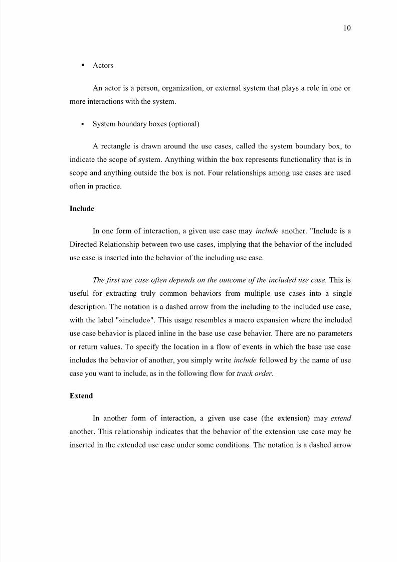
Brief Description:
The administrator chooses change password
Initial step-by-step description:
1. The first step is to choose Change password
2. First the old password is entered
3. Then new password, confirm password is entered
4. The data is submitted
5. The data is update and the next time when the administrator logins next time the new
password is applied
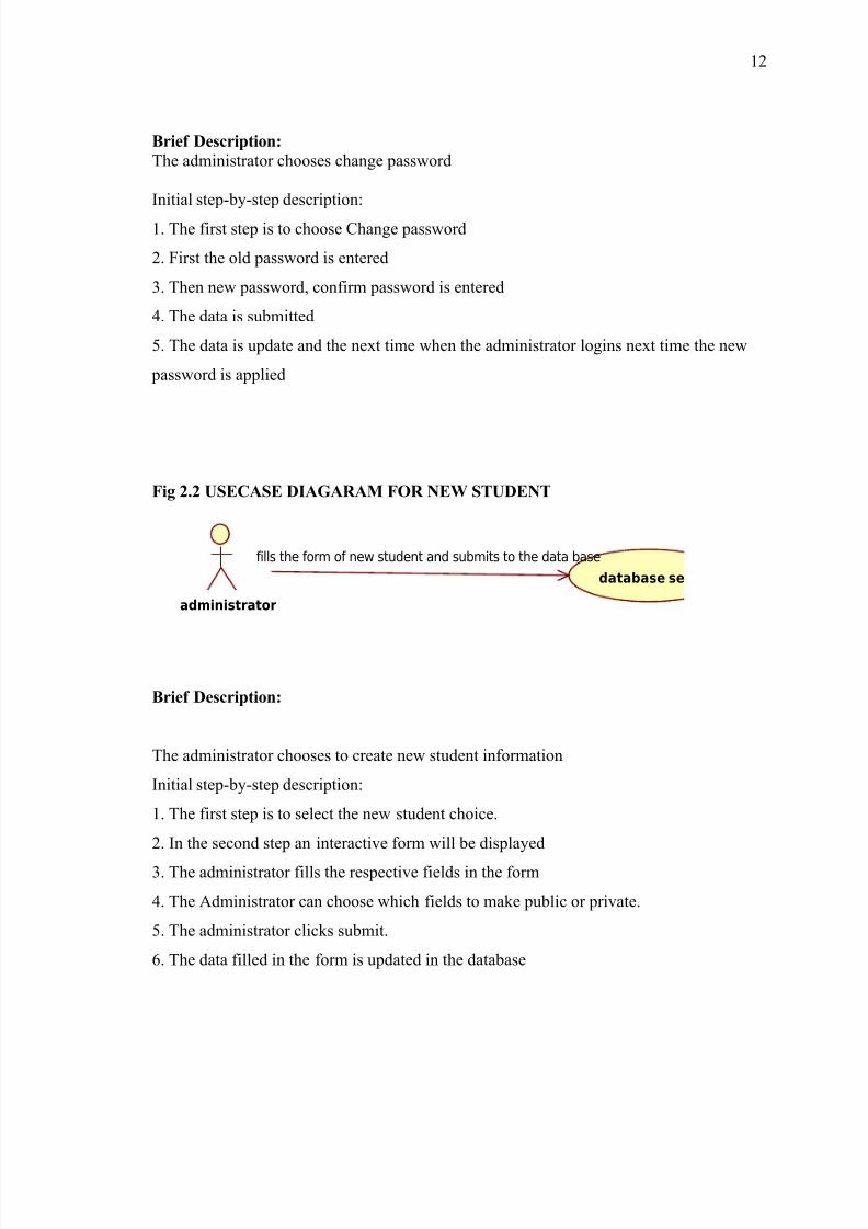
Fig 2.2 USECASE DIAGARAM FOR NEW STUDENT
administrator
database se
fills the form of new student and submits to the data base
Brief Description:
The administrator chooses to create new student information
Initial step-by-step description:
1. The first step is to select the new student choice.
2. In the second step an interactive form will be displayed
3. The administrator fills the respective fields in the form
4. The Administrator can choose which fields to make public or private.
5. The administrator clicks submit.
6. The data filled in the form is updated in the database
12

8/3/2019 Hostel New
http://slidepdf.com/reader/full/hostel-new 13/88
7. Then respective information is displayed
Fig 2.3 USECASE DIAGARAM FOR NEW STUDENT ROOM ALLOTMENT
administrator
availability
checks for the availability
databas
enters the room no and submits
Brief Description:
The administrator chooses to New Student Room Allotment.
Initial step-by-step description:
1. The first step is to select the new student room allotment
2. The availability of rooms is verified in the database
3. If the room is available then corresponding room no and vacancies are displayed
4. Then the room no is entered and then submit is clicked
5. Then the data is updated in the database
6. The message of entry is displayed
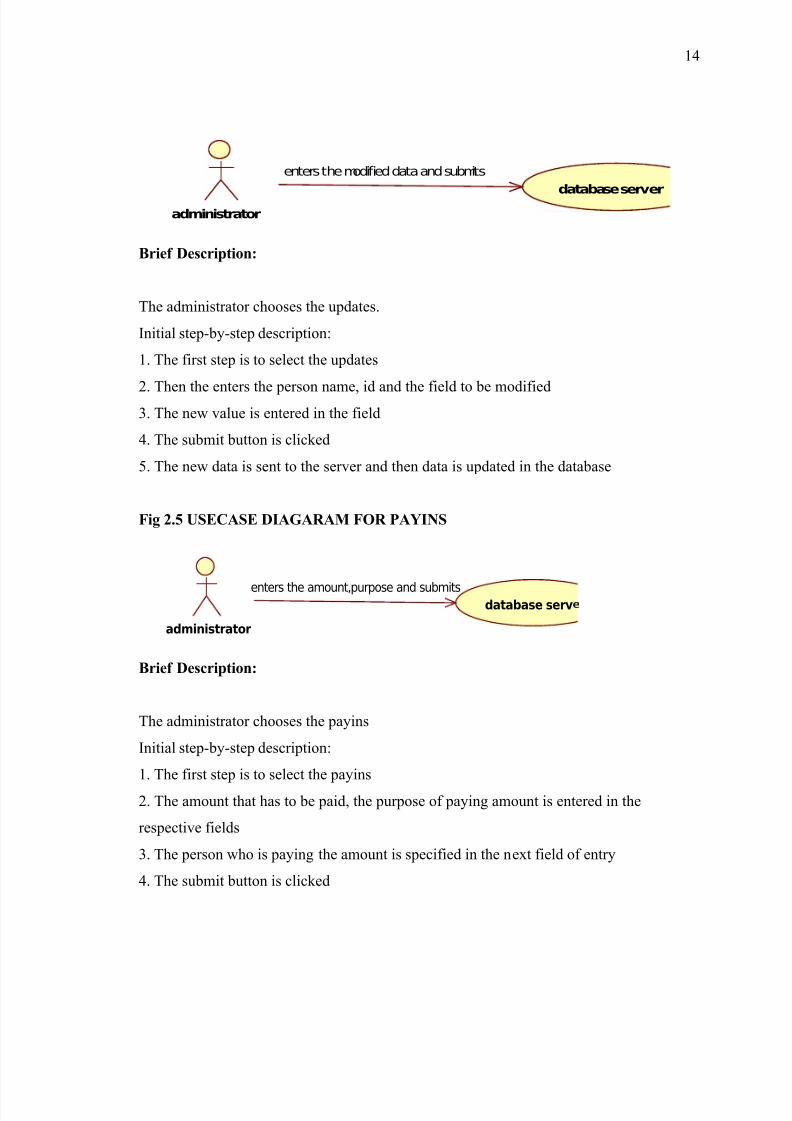
Fig 2.4 USECASE DIAGARAM FOR UPDATES
13
8/3/2019 Hostel New
http://slidepdf.com/reader/full/hostel-new 14/88
administrator
database server
enters the modified data and submits
Brief Description:
The administrator chooses the updates.
Initial step-by-step description:
1. The first step is to select the updates
2. Then the enters the person name, id and the field to be modified3. The new value is entered in the field
4. The submit button is clicked
5. The new data is sent to the server and then data is updated in the database
Fig 2.5 USECASE DIAGARAM FOR PAYINS
administrator
database serventers the amount,purpose and submits
Brief Description:
The administrator chooses the payins
Initial step-by-step description:
1. The first step is to select the payins
2. The amount that has to be paid, the purpose of paying amount is entered in the
respective fields
3. The person who is paying the amount is specified in the next field of entry
4. The submit button is clicked
14
8/3/2019 Hostel New
http://slidepdf.com/reader/full/hostel-new 15/88
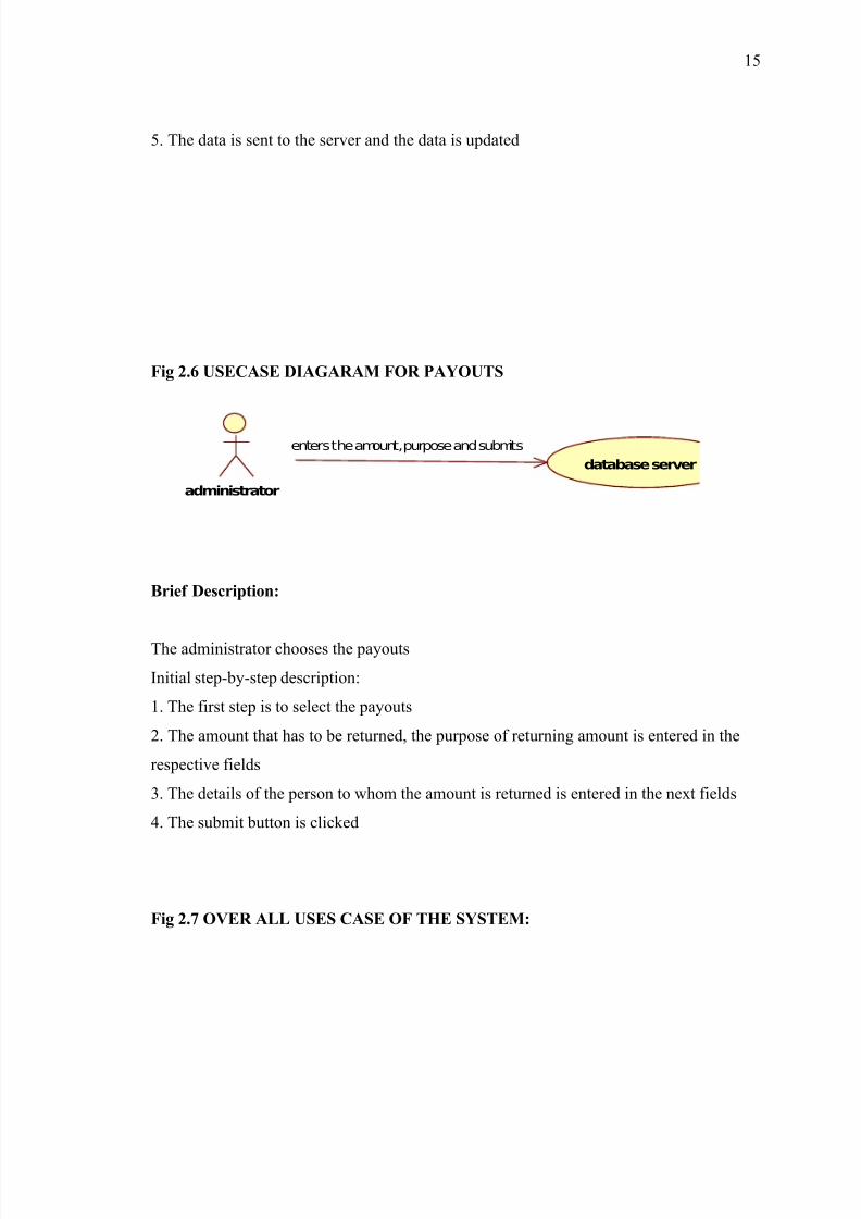
5. The data is sent to the server and the data is updated
Fig 2.6 USECASE DIAGARAM FOR PAYOUTS
administrator
database server
enters the amount,purpose and submits
Brief Description:
The administrator chooses the payouts
Initial step-by-step description:
1. The first step is to select the payouts
2. The amount that has to be returned, the purpose of returning amount is entered in the
respective fields
3. The details of the person to whom the amount is returned is entered in the next fields
4. The submit button is clicked
Fig 2.7 OVER ALL USES CASE OF THE SYSTEM:
15
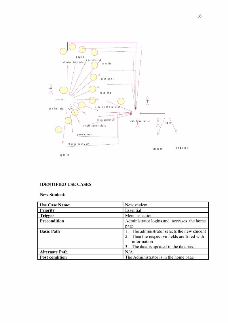
8/3/2019 Hostel New
http://slidepdf.com/reader/full/hostel-new 16/88
a d m i n s t r a t o r
p a y o u t s
l o g i n
u p d a t e s
c h a n g e p a s s w o r d
m e d i c i n e i n fo
r o o m a l l o t m e n t
u s e r l o g i n s
i n fr a s t r u c t u r a l i n f o
p a y i n s
r o o m i n fo
c r e a t io n o f n e w u s e r
r e t u rn p e r m i s s i o n s
p e r m i s s i o n s
s t u d e n t e m p l o y e e
u s e r d a t a b a s e s e r v e r
IDENTIFIED USE CASES
New Student:
Use Case Name: New student
Priority Essential
Trigger Menu selection
Precondition Administrator logins and accesses the home
pageBasic Path 1. The administrator selects the new student
2. Then the respective fields are filled withinformation
3. The data is updated in the database
Alternate Path N/A
Post condition The Administrator is in the home page
16
8/3/2019 Hostel New
http://slidepdf.com/reader/full/hostel-new 17/88
Reference
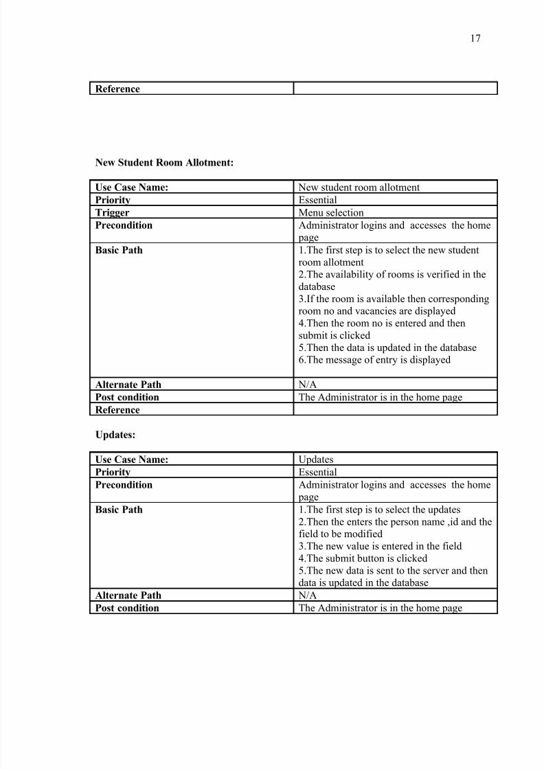
New Student Room Allotment:
Use Case Name: New student room allotment
Priority Essential
Trigger Menu selection
Precondition Administrator logins and accesses the home page
Basic Path 1.The first step is to select the new studentroom allotment2.The availability of rooms is verified in thedatabase3.If the room is available then correspondingroom no and vacancies are displayed4.Then the room no is entered and thensubmit is clicked5.Then the data is updated in the database6.The message of entry is displayed
Alternate Path N/A
Post condition The Administrator is in the home page
Reference
Updates:
Use Case Name: Updates
Priority Essential
Precondition Administrator logins and accesses the home page
Basic Path 1.The first step is to select the updates2.Then the enters the person name ,id and thefield to be modified3.The new value is entered in the field4.The submit button is clicked5.The new data is sent to the server and thendata is updated in the database
Alternate Path N/A
Post condition The Administrator is in the home page
17
8/3/2019 Hostel New
http://slidepdf.com/reader/full/hostel-new 18/88
Reference
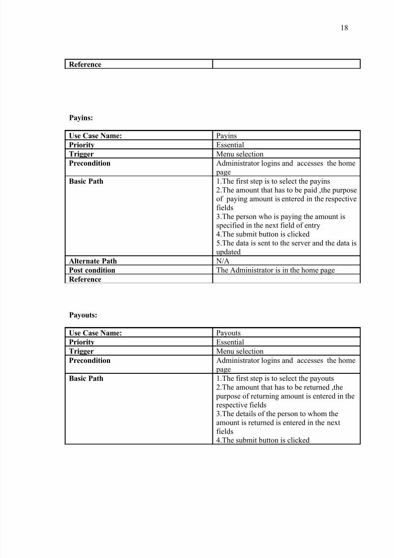
Payins:
Use Case Name: Payins
Priority Essential
Trigger Menu selection
Precondition Administrator logins and accesses the home page
Basic Path 1.The first step is to select the payins2.The amount that has to be paid ,the purposeof paying amount is entered in the respectivefields3.The person who is paying the amount isspecified in the next field of entry4.The submit button is clicked5.The data is sent to the server and the data isupdated
Alternate Path N/A
Post condition The Administrator is in the home page
Reference
Payouts:
Use Case Name: Payouts
Priority Essential
Trigger Menu selection
Precondition Administrator logins and accesses the home page
Basic Path 1.The first step is to select the payouts
2.The amount that has to be returned ,the purpose of returning amount is entered in therespective fields3.The details of the person to whom theamount is returned is entered in the nextfields4.The submit button is clicked
18
8/3/2019 Hostel New
http://slidepdf.com/reader/full/hostel-new 19/88
Alternate Path N/A
Post condition The Administrator is in the home page
Reference
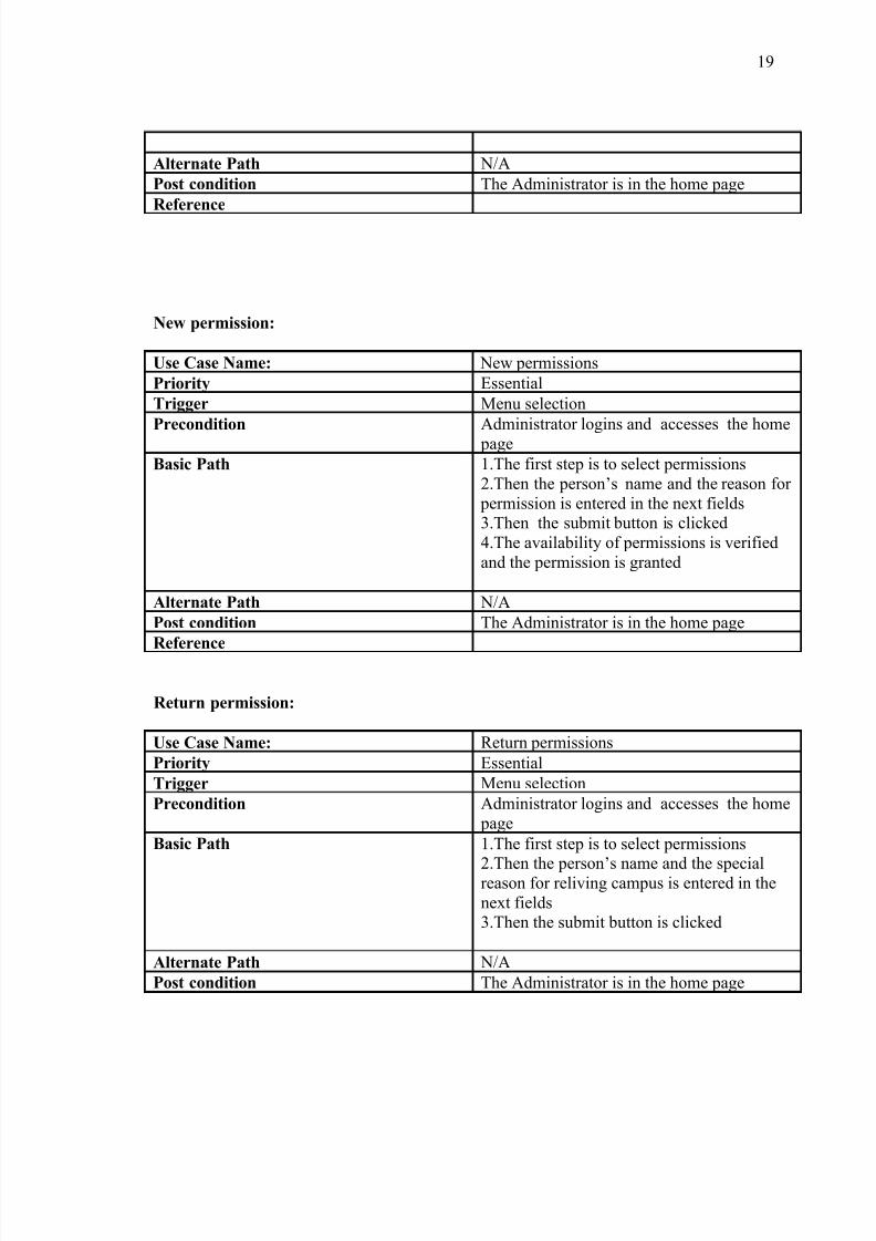
New permission:
Use Case Name: New permissions
Priority Essential
Trigger Menu selection
Precondition Administrator logins and accesses the home page
Basic Path 1.The first step is to select permissions2.Then the person’s name and the reason for permission is entered in the next fields3.Then the submit button is clicked4.The availability of permissions is verifiedand the permission is granted
Alternate Path N/A
Post condition The Administrator is in the home page
Reference
Return permission:
Use Case Name: Return permissions
Priority Essential
Trigger Menu selection
Precondition Administrator logins and accesses the home page
Basic Path 1.The first step is to select permissions
2.Then the person’s name and the specialreason for reliving campus is entered in thenext fields3.Then the submit button is clicked
Alternate Path N/A
Post condition The Administrator is in the home page
19

8/3/2019 Hostel New
http://slidepdf.com/reader/full/hostel-new 20/88
Reference
Monthly bill -cal:
Use Case Name: Monthly bill-cal
Priority Essential
Trigger Menu selection
Precondition Administrator logins and accesses the home page
Basic Path 1.The first step is to choose the monthly billcalculate
2.Then the month and year fields are filled3.After that submit button is clicked4.The total bill of that particular month is
displayed
Alternate Path N/A
Post condition The Administrator is in the home page
Reference
Rooms-info:
Use Case Name: Rooms-info
Priority Essential
Trigger Menu selection
Precondition Administrator logins and accesses the home page
Basic Path 1.The first step is to choose the rooms2.Then the room no, type of room ,personinformation is entered3.Administrator clicks the submits
Alternate Path N/A
20

8/3/2019 Hostel New
http://slidepdf.com/reader/full/hostel-new 21/88
Post condition The Administrator is in the home page
Reference
Medicines-info:
Use Case Name: Medicines-info
Priority Essential
Trigger Menu selection
Precondition Administrator logins and accesses the home page
Basic Path 1.The first step is to choose the Medicine-info2.Then the name of medicine ,mfgd date,expiry date and quantity is used is entered3.The action and usage of medicine is alsoentered4.Administrators clicks the submits
Alternate Path N/A
Post condition The Administrator is in the home page
Reference
Infrastructure-info:
Use Case Name: Infrastructure-info
Priority Essential
Trigger Menu selection
Precondition Administrator logins and accesses the home page
Basic Path 1.The first step is to choose Infrastructure-
info2.The items ,quantity available are entered3.Submit button is clicked4.The data is sent to the server and thedatabase is updated
Alternate Path N/A
21
8/3/2019 Hostel New
http://slidepdf.com/reader/full/hostel-new 22/88
Post condition The Administrator is in the home page
Reference
Change password:
Use Case Name: Change password
Priority Essential
Trigger Menu selection
Precondition Administrator logins and accesses the home page
Basic Path 1.The first step is to choose Change password2.First the old password is entered3.Then new password, confirm password isentered4.The data is submitted5.The data is update and the next time whenthe administrator logins next time the new password is applied
Alternate Path N/A
Post condition The Administrator is in the home page
Reference
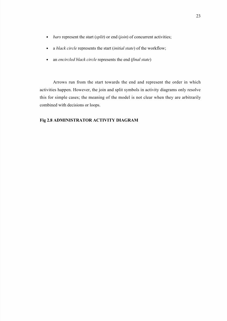
2.1.2 ACTIVITY DIAGRAM:
Activity diagrams are graphical representations of workflows of stepwise activities
and actions with support for choice, iteration and concurrency. In the Unified Modeling
Language, activity diagrams can be used to describe the business and operational step-by-
step workflows of components in a system. An activity diagram shows the overall flow of
control. Activity diagrams are constructed from a limited repertoire of shapes, connected
with arrows. The most important shape types:
• rounded rectangles represent activities;
• diamonds represent decisions;
22
8/3/2019 Hostel New
http://slidepdf.com/reader/full/hostel-new 23/88
• bars represent the start ( split ) or end ( join) of concurrent activities;
• a black circle represents the start (initial state) of the workflow;
• an encircled black circle represents the end ( final state)
Arrows run from the start towards the end and represent the order in which
activities happen. However, the join and split symbols in activity diagrams only resolve
this for simple cases; the meaning of the model is not clear when they are arbitrarily
combined with decisions or loops.
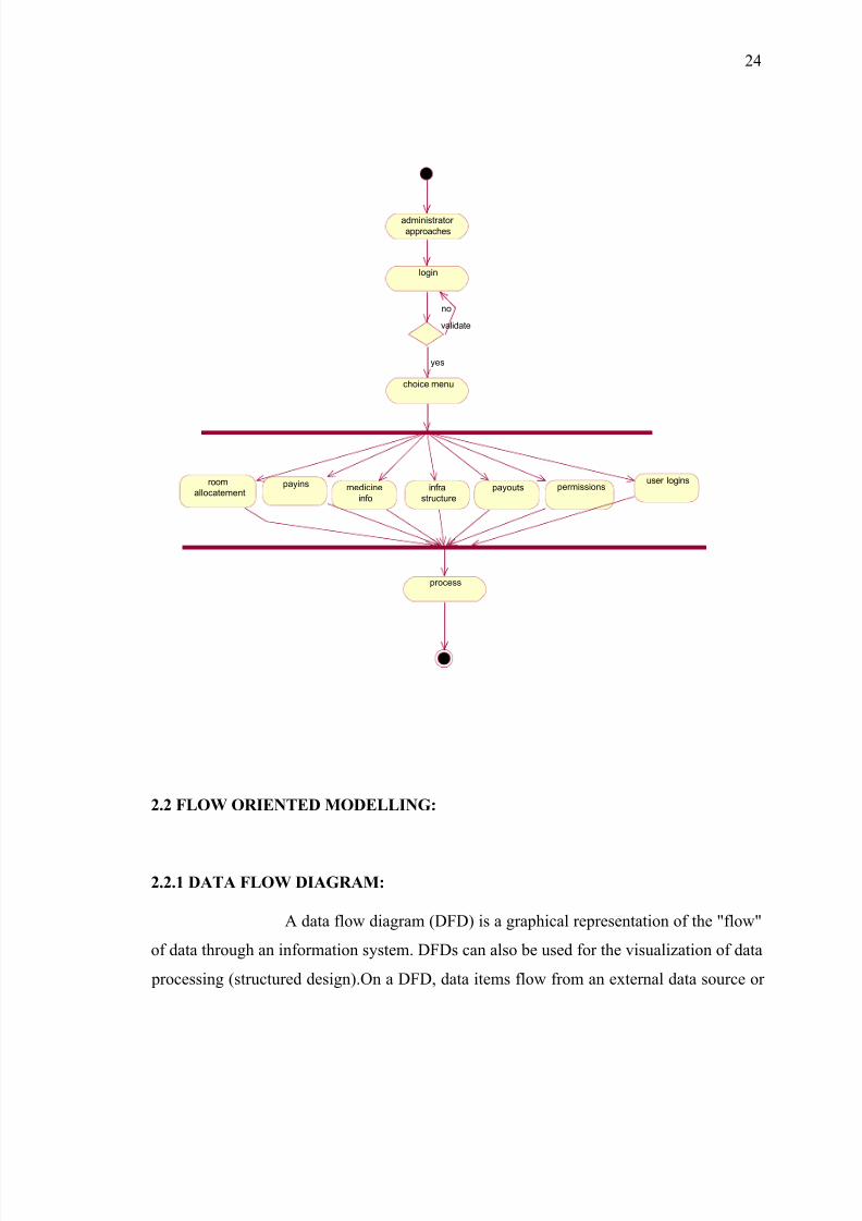
Fig 2.8 ADMINISTRATOR ACTIVITY DIAGRAM
23
8/3/2019 Hostel New
http://slidepdf.com/reader/full/hostel-new 24/88
administrator
approaches
login
validate
no
choice menu
yes
payins medicine
info
infra
structure
payouts permissionsroom
allocatement
user logins
process
2.2 FLOW ORIENTED MODELLING:
2.2.1 DATA FLOW DIAGRAM:
A data flow diagram (DFD) is a graphical representation of the "flow"
of data through an information system. DFDs can also be used for the visualization of data
processing (structured design).On a DFD, data items flow from an external data source or
24
8/3/2019 Hostel New
http://slidepdf.com/reader/full/hostel-new 25/88
an internal data store to an internal data store or an external data sink, via an internal
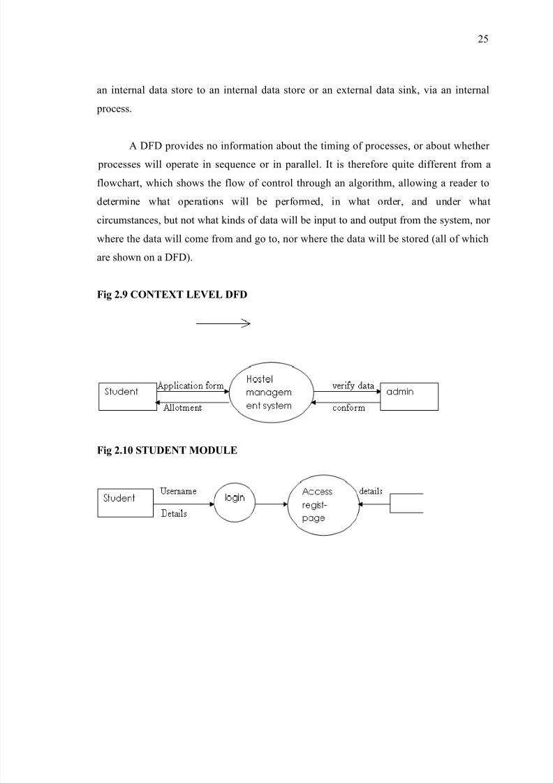
process.
A DFD provides no information about the timing of processes, or about whether
processes will operate in sequence or in parallel. It is therefore quite different from a
flowchart, which shows the flow of control through an algorithm, allowing a reader to
determine what operations will be performed, in what order, and under what
circumstances, but not what kinds of data will be input to and output from the system, nor
where the data will come from and go to, nor where the data will be stored (all of which
are shown on a DFD).
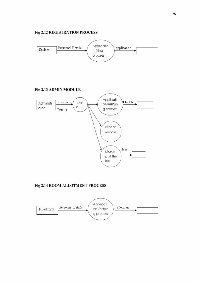
Fig 2.9 CONTEXT LEVEL DFD
Fig 2.10 STUDENT MODULE
25
8/3/2019 Hostel New
http://slidepdf.com/reader/full/hostel-new 26/88
Fig 2.12 REGISTRATION PROCESS
Fig 2.13 ADMIN MODULE
Fig 2.14 ROOM ALLOTMENT PROCESS
26
8/3/2019 Hostel New
http://slidepdf.com/reader/full/hostel-new 27/88
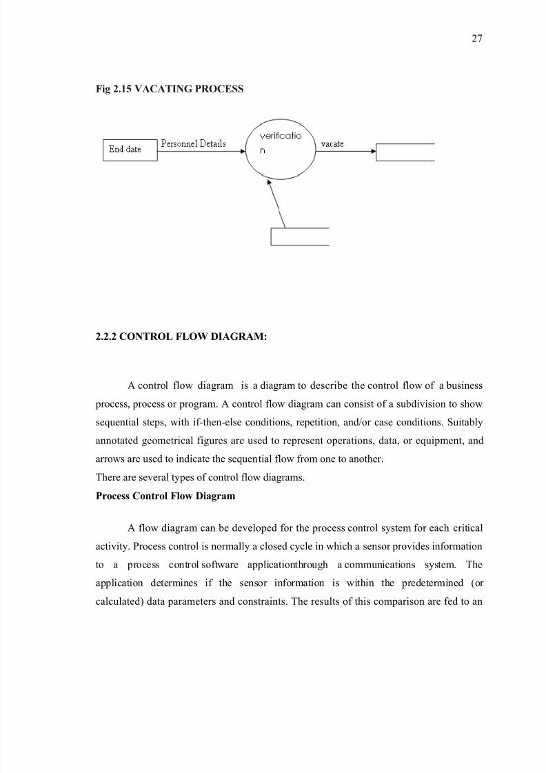
Fig 2.15 VACATING PROCESS
2.2.2 CONTROL FLOW DIAGRAM:
A control flow diagram is a diagram to describe the control flow of a business
process, process or program. A control flow diagram can consist of a subdivision to showsequential steps, with if-then-else conditions, repetition, and/or case conditions. Suitably
annotated geometrical figures are used to represent operations, data, or equipment, and
arrows are used to indicate the sequential flow from one to another.
There are several types of control flow diagrams.
Process Control Flow Diagram
A flow diagram can be developed for the process control system for each critical
activity. Process control is normally a closed cycle in which a sensor provides information
to a process control software applicationthrough a communications system. The
application determines if the sensor information is within the predetermined (or
calculated) data parameters and constraints. The results of this comparison are fed to an
27
8/3/2019 Hostel New
http://slidepdf.com/reader/full/hostel-new 28/88
actuator, which controls the critical component. This feedback may control the component
electronically or may indicate the need for a manual action
Performance seeking control flow diagram
The figure presents an example of a performance seeking control flow diagram of
the algorithm. The control law consists of estimation, modeling, and optimization
processes. In the Kalman filter estimator, the inputs, outputs, and residuals were recorded.
At the compact propulsion system modeling stage, all the estimated inlet and engine
parameters were recorded
Fig 2.16 OVERALL CONTROL FLOW DAIGRAM FOR SYSTEM
28

8/3/2019 Hostel New
http://slidepdf.com/reader/full/hostel-new 29/88
2.3 BEHAVIORAL MODELING:
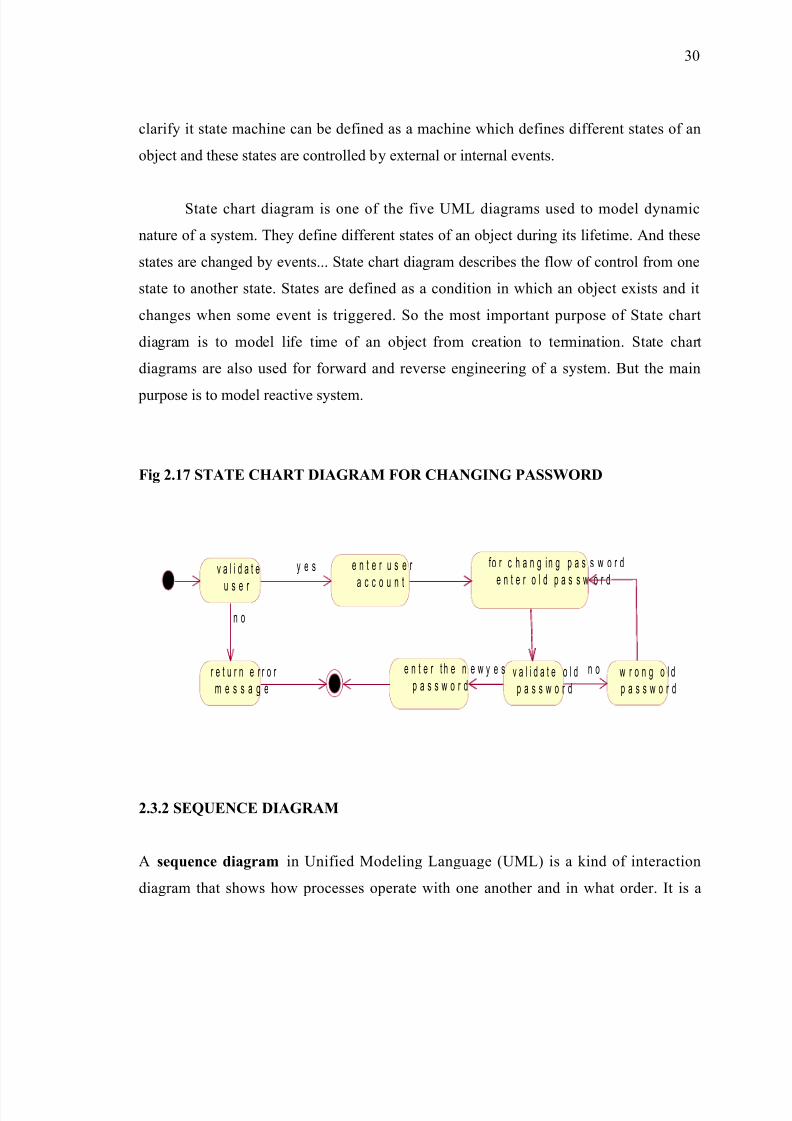
2.3.1 STATECHART DIAGRAM:
The name of the diagram itself clarifies the purpose of the diagram and other
details. It describes different states of a component in a system. The states are specific
component/object of a system. A State chart diagram describes a state machine. Now to
29
8/3/2019 Hostel New
http://slidepdf.com/reader/full/hostel-new 30/88
clarify it state machine can be defined as a machine which defines different states of an
object and these states are controlled by external or internal events.
State chart diagram is one of the five UML diagrams used to model dynamic
nature of a system. They define different states of an object during its lifetime. And these
states are changed by events... State chart diagram describes the flow of control from one
state to another state. States are defined as a condition in which an object exists and it
changes when some event is triggered. So the most important purpose of State chart
diagram is to model life time of an object from creation to termination. State chart
diagrams are also used for forward and reverse engineering of a system. But the main
purpose is to model reactive system.
Fig 2.17 STATE CHART DIAGRAM FOR CHANGING PASSWORD
v a l i d a t e
u s e r
e n t e r u s e r
a c c o u n t
y e s
r e t u r n e r r o r m e s s a g e
n o
fo r c h a n g i n g p a s s w o r de n t e r o l d p a s s w o r d
v a l i d a t e o l dp a s s w o r d
e n t e r t h e n e w
p a s s w o r dy e s w r o n g o l d
p a s s w o r d
n o
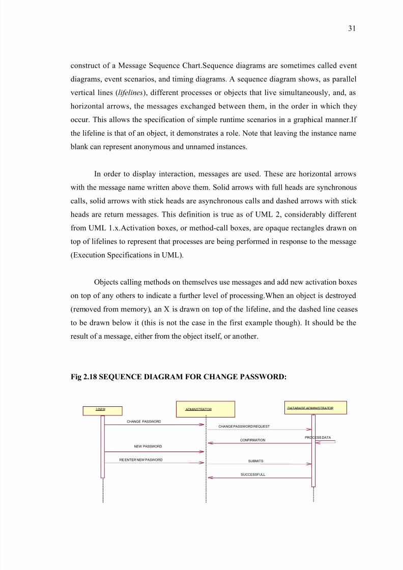
2.3.2 SEQUENCE DIAGRAM
A sequence diagram in Unified Modeling Language (UML) is a kind of interaction
diagram that shows how processes operate with one another and in what order. It is a
30
8/3/2019 Hostel New
http://slidepdf.com/reader/full/hostel-new 31/88
construct of a Message Sequence Chart.Sequence diagrams are sometimes called event
diagrams, event scenarios, and timing diagrams. A sequence diagram shows, as parallel
vertical lines (lifelines), different processes or objects that live simultaneously, and, as
horizontal arrows, the messages exchanged between them, in the order in which they
occur. This allows the specification of simple runtime scenarios in a graphical manner.If
the lifeline is that of an object, it demonstrates a role. Note that leaving the instance name
blank can represent anonymous and unnamed instances.
In order to display interaction, messages are used. These are horizontal arrows
with the message name written above them. Solid arrows with full heads are synchronous
calls, solid arrows with stick heads are asynchronous calls and dashed arrows with stick
heads are return messages. This definition is true as of UML 2, considerably different
from UML 1.x.Activation boxes, or method-call boxes, are opaque rectangles drawn on
top of lifelines to represent that processes are being performed in response to the message
(Execution Specifications in UML).
Objects calling methods on themselves use messages and add new activation boxes
on top of any others to indicate a further level of processing.When an object is destroyed(removed from memory), an X is drawn on top of the lifeline, and the dashed line ceases
to be drawn below it (this is not the case in the first example though). It should be the
result of a message, either from the object itself, or another.
Fig 2.18 SEQUENCE DIAGRAM FOR CHANGE PASSWORD:
31
ADMINSTRATOR DATABASE ADMINISTRATORUSER
CHANGE PASSWORD REQUEST
CONFIRMATIONPROCESS DATA
CHANGE PASSWORD
NEW PASSWORD
RE ENTER NEW PASWORD SUBMITS
SUCCESSFULL
8/3/2019 Hostel New
http://slidepdf.com/reader/full/hostel-new 32/88
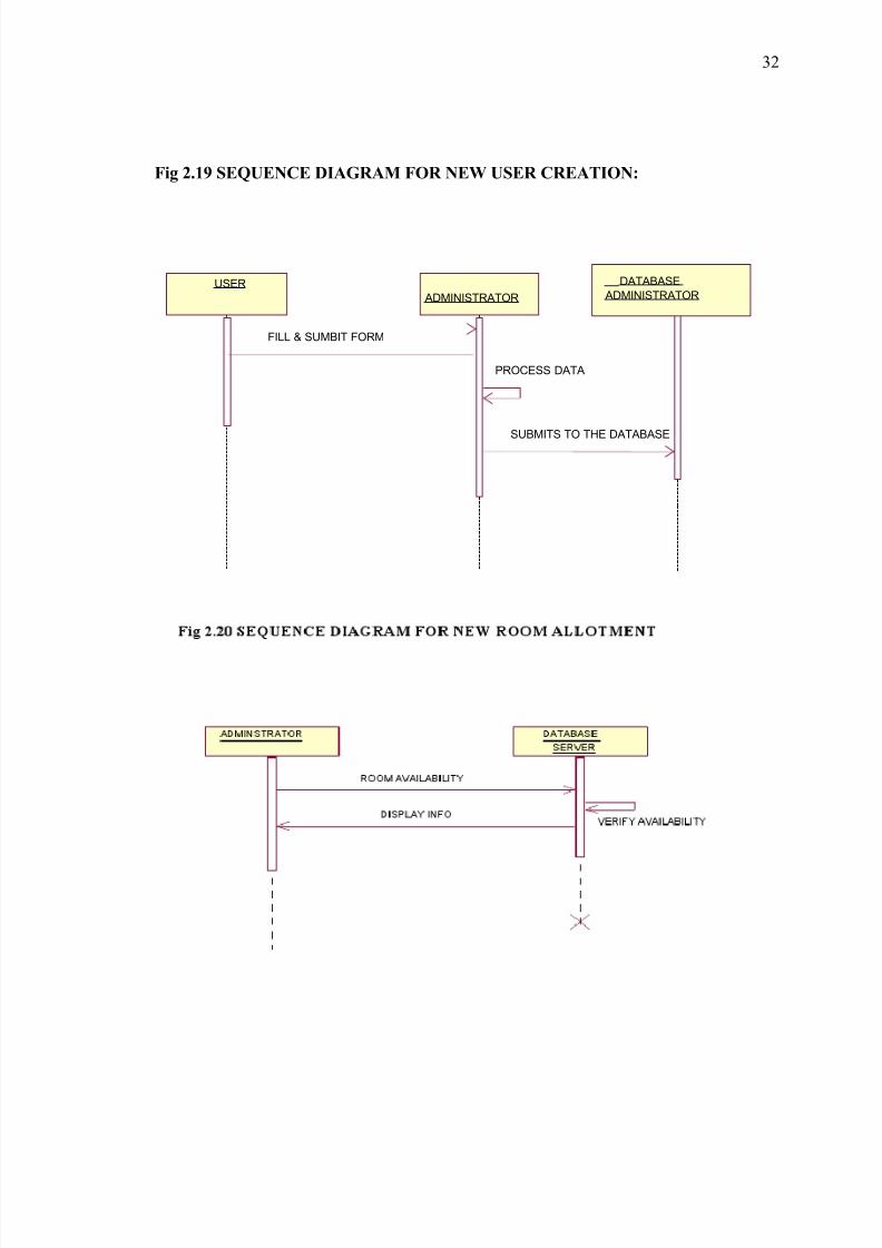
Fig 2.19 SEQUENCE DIAGRAM FOR NEW USER CREATION:
32
USER
ADMINISTRATOR
FILL & SUMBIT FORM
PROCESS DATA
SUBMITS TO THE DATABASE
DATABASE
ADMINISTRATOR
8/3/2019 Hostel New
http://slidepdf.com/reader/full/hostel-new 33/88
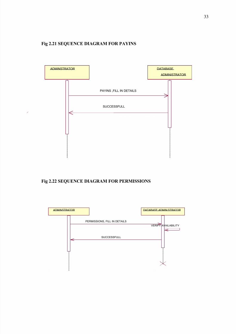
Fig 2.21 SEQUENCE DIAGRAM FOR PAYINS
Fig 2.22 SEQUENCE DIAGRAM FOR PERMISSIONS
33
ADMINSTRATOR DATABASE
ADMINISTRATOR
PAYINS ,FILL IN DETAILS
SUCCESSFULL
ADMINSTRATOR DATABASE ADMINISTRATOR
PERMISSIONS, FILL IN DETAILS
SUCCESSFULL
VERIFY AVAILABILITY
8/3/2019 Hostel New
http://slidepdf.com/reader/full/hostel-new 34/88
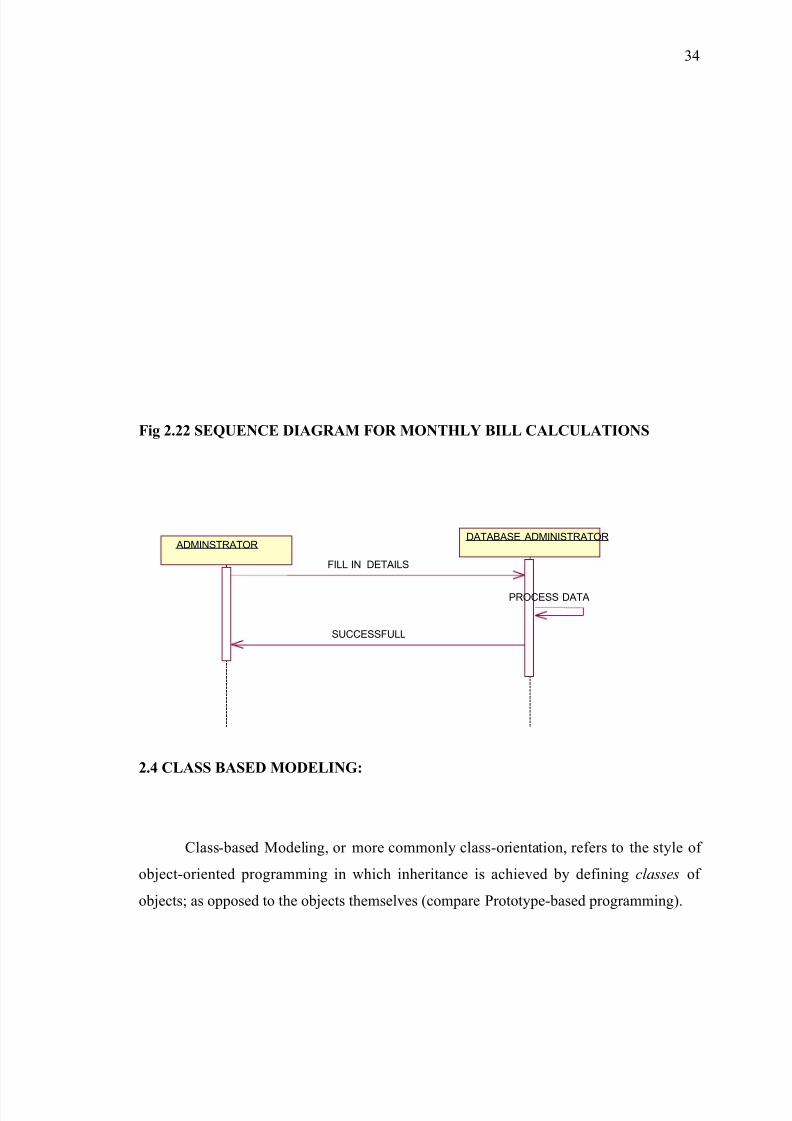
Fig 2.22 SEQUENCE DIAGRAM FOR MONTHLY BILL CALCULATIONS
2.4 CLASS BASED MODELING:
Class-based Modeling, or more commonly class-orientation, refers to the style of
object-oriented programming in which inheritance is achieved by defining classes of
objects; as opposed to the objects themselves (compare Prototype-based programming).
34
ADMINSTRATORDATABASE ADMINISTRATOR
FILL IN DETAILS
SUCCESSFULL
PROCESS DATA
8/3/2019 Hostel New
http://slidepdf.com/reader/full/hostel-new 35/88
The most popular and developed model of OOP is a class-based model, as opposed
to an object-based model. In this model, objects are entities that combine state (i.e., data),
behavior (i.e., procedures, or methods) and identity (unique existence among all other
objects). The structure and behavior of an object are defined by a class, which is a
definition, or blueprint, of all objects of a specific type. An object must be explicitly
created based on a class and an object thus created is considered to be an instance of that
class. An object is similar to a structure, with the addition of method pointers, member
access control, and an implicit data member which locates instances of the class (i.e.
actual objects of that class) in the class hierarchy (essential for runtime inheritance
features).
2.4.1 IDENTIFIED CLASSES:
Class Name : Administrator
Attributes : Name, I D
Responsibilities: login(), cereatenewuser(), permssions(), roomallocation(),payins(),
payouts(),medicineinfo(),infrastructureinfo().
Class Name : student
Attributes : Name ,age ,studentid, roomno ,roomtype , year ,eatinghabbits.
Responsibilities: checkaccountinfo() ,changepassword() ,displayinfo()
Class Name : employee
Attributes : Name ,age ,employeeid, roomno ,roomtype , salary ,eatinghabbits.
Responsibilities: checkaccountinfo() ,changepassword() ,displayinfo()
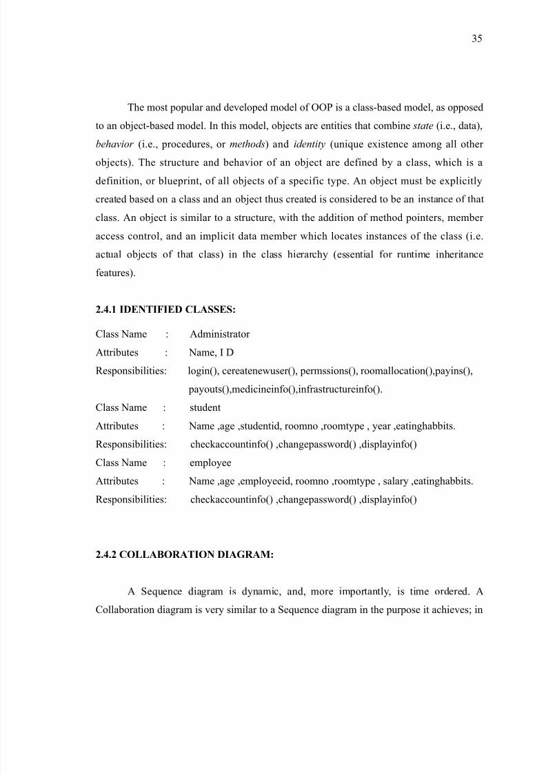
2.4.2 COLLABORATION DIAGRAM:
A Sequence diagram is dynamic, and, more importantly, is time ordered. A
Collaboration diagram is very similar to a Sequence diagram in the purpose it achieves; in
35
8/3/2019 Hostel New
http://slidepdf.com/reader/full/hostel-new 36/88
other words, it shows the dynamic interaction of the objects in a system. A distinguishing
feature of a Collaboration diagram is that it shows the objects and their association with
other objects in the system apart from how they interact with each other. The association
between objects is not represented in a Sequence diagram.
A Collaboration diagram is easily represented by modeling objects in a system and
representing the associations between the objects as links. The interaction between the
objects is denoted by arrows. To identify the sequence of invocation of these objects, a
number is placed next to each of these arrows.
A sophisticated modeling tool can easily convert a collaboration diagram into a
sequence diagram and the vice versa. Hence, the elements of a Collaboration diagram are
essentially the same as that of a Sequence diagram.
Fig 2.14 COLLABORATION DIAGARAM FOR CHANGE OF PASSWORD:
USER
ADMINISTRATOR
DATABASE SERVER
1: CHANGE PASSWORD
2: CHANGE PASSWORDREQUEST
3: PROCESS DATA
4: CONFIRMATION
5: NEW PASSWORD
6: RE-ENTERNEW PASSWORD
7: SUBMITS
8: SUCCESSFULL
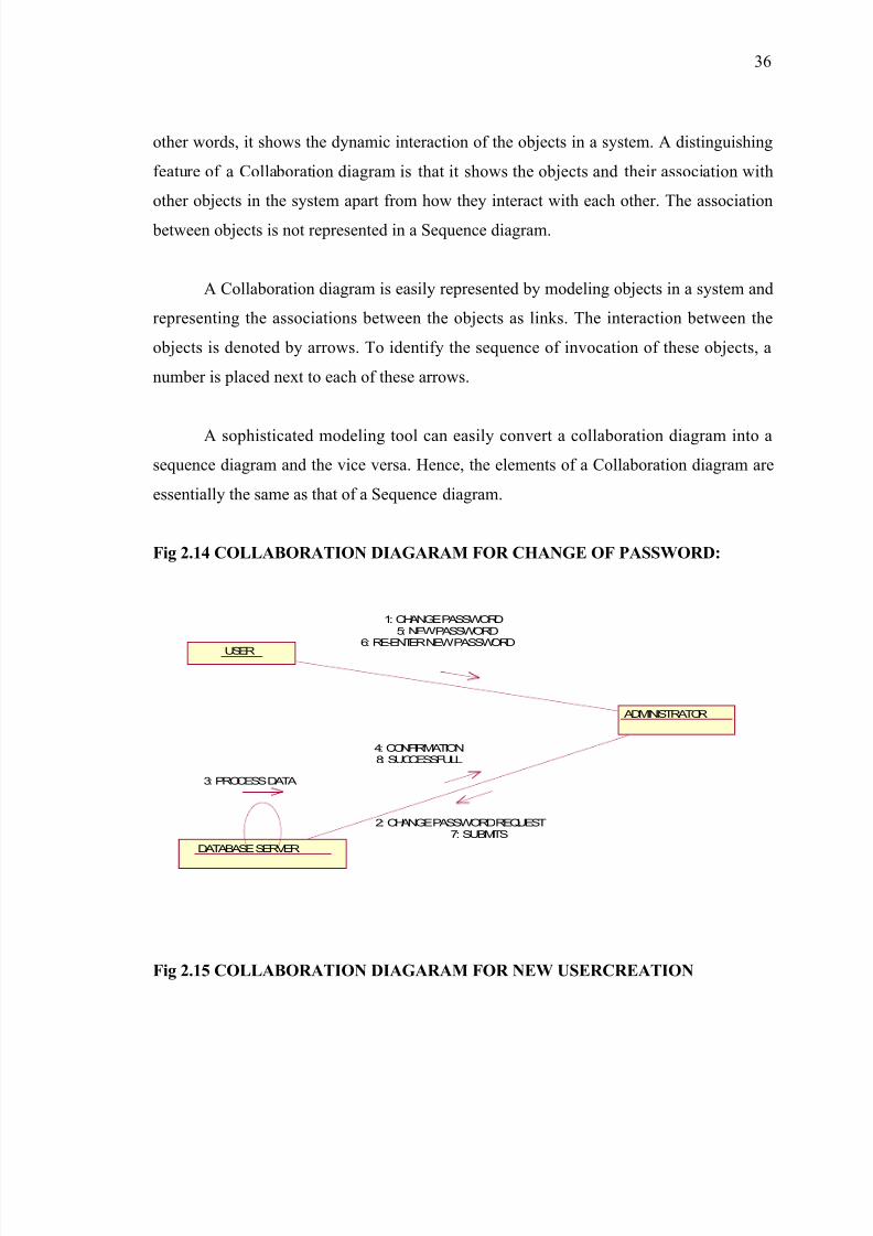
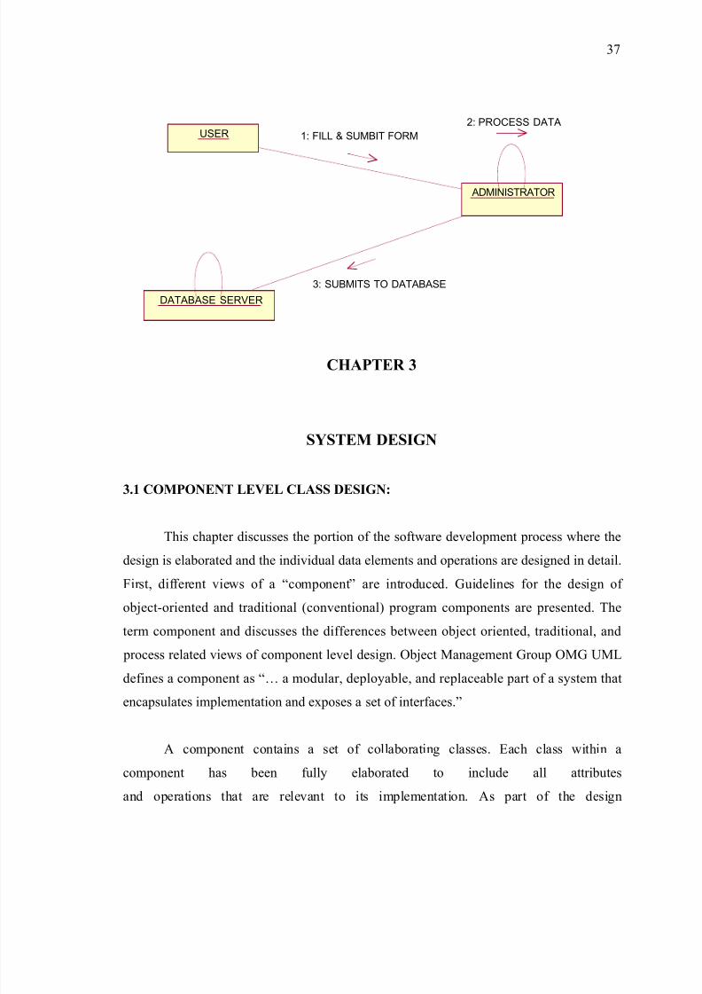
Fig 2.15 COLLABORATION DIAGARAM FOR NEW USERCREATION
36
8/3/2019 Hostel New
http://slidepdf.com/reader/full/hostel-new 37/88
USER
ADMINISTRATOR
DATABASE SERVER
1: FILL & SUMBIT FORM
2: PROCESS DATA
3: SUBMITS TO DATABASE
CHAPTER 3
SYSTEM DESIGN
3.1 COMPONENT LEVEL CLASS DESIGN:
This chapter discusses the portion of the software development process where the
design is elaborated and the individual data elements and operations are designed in detail.
First, different views of a “component” are introduced. Guidelines for the design of
object-oriented and traditional (conventional) program components are presented. The
term component and discusses the differences between object oriented, traditional, and
process related views of component level design. Object Management Group OMG UML
defines a component as “… a modular, deployable, and replaceable part of a system that
encapsulates implementation and exposes a set of interfaces.”
A component contains a set of collaborating classes. Each class within a
component has been fully elaborated to include all attributes
and operations that are relevant to its implementation. As part of the design
37
8/3/2019 Hostel New
http://slidepdf.com/reader/full/hostel-new 38/88
elaboration, all interfaces (messages) that enable the classes to communicate and
collaborate with other design classes must also be defined. To accomplish this,
the designer begins with the analysis model and elaborates analysis classes (for
components that relate to the problem domain) and infrastructure classes (or
components that provide support services for the problem domain).
3.2 ARCHITECTURAL DESIGN:
3.2.1 PROCEDURAL STEPS FOR DESIGN:
1. The systematic analysis principles applied to function and behavior should also be
applied to data.
2. All data structures and the operations to be performed on each should be identified.
3. A data dictionary should be established and used to define both data and program
design.
4. Low level data design decisions should be deferred until late in the design process.
5. The representation of data structure should be known only to those modules that must
make direct use of the data contained within the structure.
6. A library of useful data structures and the operations that may be applied to them
should be developed.
3.2.2 ARCHITECTURAL DESIGN DIAGRAMS:
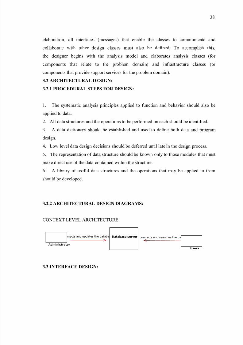
CONTEXT LEVEL ARCHITECTURE:
3.3 INTERFACE DESIGN:
Administrator
Connects and updates the database
Users
connects and searches the dataDatabase server
38
8/3/2019 Hostel New
http://slidepdf.com/reader/full/hostel-new 39/88
User interface design or user interface engineering is the design of computers,
appliances, machines, mobile communication devices, software applications, and websites
with the focus on the user's experience and interaction. The goal of user interface design is
to make the user's interaction as simple and efficient as possible, in terms of
accomplishing user goals—what is often called user-centered design. Good user interface
design facilitates finishing the task at hand without drawing unnecessary attention to itself.
Graphic design may be utilized to support its usability. The design process must balance
technical functionality and visual elements (e.g., mental model) to create a system that is
not only operational but also usable and adaptable to changing user needs.
Interface design is involved in a wide range of projects from computer systems, to
cars, to commercial planes; all of these projects involve much of the same basic human
interactions yet also require some unique skills and knowledge. As a result, designers tend
to specialize in certain types of projects and have skills centered around their expertise,
whether that be software design, user research, web design, or industrial design.
3.3.1 INTERFACE DESIGN PROCEDURAL STEPS:
There are several phases and processes in the user interface design, some of which are
more demanded upon than others, depending on the project. (Note: for the remainder of
this section, the word system is used to denote any project whether it is a web site,
application, or device.)
• Functionality requirements gathering – assembling a list of the functionality
required by the system to accomplish the goals of the project and the potential
needs of the users.
• User analysis – analysis of the potential users of the system either through
discussion with people who work with the users and/or the potential users
themselves. Typical questions involve:
o What would the user want the system to do?
39
8/3/2019 Hostel New
http://slidepdf.com/reader/full/hostel-new 40/88
o How would the system fit in with the user's normal workflow or daily
activities?
o How technically savvy is the user and what similar systems does the user
already use?
o What interface look & feel styles appeal to the user?
• Information architecture – development of the process and/or information flow of
the system (i.e. for phone tree systems, this would be an option tree flowchart and
for web sites this would be a site flow that shows the hierarchy of the pages).
• Prototyping – development of wire frames, either in the form of paper prototypes
or simple interactive screens. These prototypes are stripped of all look & feel
elements and most content in order to concentrate on the interface.
• Usability testing – testing of the prototypes on an actual user—often using a
technique called think aloud protocol where you ask the user to talk about their
thoughts during the experience.
• Graphic Interface design – actual look & feel design of the final graphical user
interface (GUI). It may be based on the findings developed during the usability
testing if usability is unpredictable, or based on communication objectives and
styles that would appeal to the user. In rare cases, the graphics may drive the
prototyping, depending on the importance of visual form versus function. If the
interface requires multiple skins, there may be multiple interface designs for one
control panel, functional feature or widget. This phase is often a collaborative
effort between a graphic designer and a user interface designer, or handled by one
who is proficient in both disciplines.
3.3.2 GUI COMPONENTS AND ACTIONS:
40
8/3/2019 Hostel New
http://slidepdf.com/reader/full/hostel-new 41/88
A process of converting user originated inputs to a computer-based format. Input
design is an important part of development process since inaccurate input data are the
most common cause of errors in data processing. Erroneous entries can be controlled by
input design. It consists of developing specifications and procedures for entering data into
a system and must be in simple format. The goal of input data design is to make data entry
as easy, logical and free from errors as possible. In input data design, we design the source
document that capture the data and then select the media used to enter them into the
computer.
There are two major approaches for entering data in to the computer. They are
· Menus.
· Dialog Boxes.
Menus
A menu is a selection list that simplifies computer data access or entry. Instead of
remembering what to enter, the user chooses from a list of options. A menu limits a user
choice of response but reduce the chances for error in data entry.
Dialog Box
Dialog boxes are windows and these windows are mainly popup, which appear in
response to certain conditions that occur when a program is run. It allows the display of
bitmaps and pictures. It can have various controls like buttons, text boxes, list boxes and
combo boxes. Using these controls we can make a ‘dialog’ with the program.
The proposed system has three major inputs. They are Machine Registration, Machine
Scheduling and Request Form.
3.4 COMPONENT LEVEL DESIGN:
41
8/3/2019 Hostel New
http://slidepdf.com/reader/full/hostel-new 42/88
Component level design also called procedural design occurs after architectural
design and interface designs have been established. Here we attempt to reduce the level of
abstraction in the design, from high to low. We seek to create operational programs.
However, this is a challenging task as our efforts are prone to the introduction of errors
that are difficult to find and correct in the later stages of the software process.
Our aim is to create a design that follows a set of principles that will not only
perform translation into source code, but also do not “introduce bugs to start with”.
Component-level design establishes the algorithm details required to manipulate data
structures, effect communication between software components via their interfaces and
implement the processing algorithms allocated to each component. Component-level
design is important because it provides a means for assessing whether data structures,
interfaces and algorithms will work. Regardless of the mechanism that is used to represent
the component-level design, the data structure, interfaces and algorithms that are defined
should conform to a variety of well-established procedural design guidelines that help to
avoid errors as the procedural design evolves.
3.4.1 PROCEDURAL STEPS:
The design representations of data, architecture and interfaces form the foundation
of the component-level design. The processing narrative for each component is translated
into a procedural design model using a set of structured programming constructs. The
procedural design for each component, represented in graphical, tabular or text-based
notation, is the primary work product produced during component-level design.
Structured Programming
The constructs are sequence, conditions and repetition. These three constructs are
fundamental to structured programming – an important component-level design
technique.
42
8/3/2019 Hostel New
http://slidepdf.com/reader/full/hostel-new 43/88
• Graphical Design Notation
• Tabular Design Notation
• Program Design Language (PDL)
A comparison must be predicated on the premise that any notation for component-
level design, if used correctly, can be an invaluable aid in the design process; conversely,
even the best notation, if poorly applied adds little to understanding. Design notation
should lead to a procedural representation that is easy to understand and review. The
design representation must be easily maintainable so that design always represents the
program correctly. The following are some attributes that will help us to favorably
compare design notations:
• Overall Simplicity: A design notation should be relatively simple to use
• Ease of Editing: The ease with which a design representation can be edited can
help facilitate each software engineering task.
•Machine Readability: A notation that can be input directly into a computer based
development system offers significant benefits.
• Structure Enforcement: A design notation that enforces that use of only
structured constructs promotes good design practice•Data Representation: A design representation should represent such data directly
Logic Verification: A notation that enhances the ability to verify logic greatly
improves testing adequacy
•“Code-to” Ability: A notation that may be converted easily to source code reduces
effort and error.
3.4.2 DETAILED CLASS DIAGRAMS:
Class Diagram:
43
8/3/2019 Hostel New
http://slidepdf.com/reader/full/hostel-new 44/88
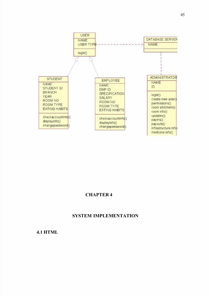
In software engineering, a class diagram in the Unified Modeling Language
(UML) is a type of static structure diagram that describes the structure of a system by
showing the system's classes, their attributes, and the relationships between the
classes.The class diagram is the main building block in object oriented modeling. It is
used both for general conceptual modeling of the semantics of the application, and for
detailed modeling translating the models into programming code. The classes in a class
diagram represent both the main objects and or interactions in the application and the
objects to be programmed. In the class diagram these classes are represented with boxes
which contain three parts:
• The upper part holds the name of the class
• The middle part contains the attributes of the class
• The bottom part gives the methods or operations the class can take or undertake
FIG: 3.1 CLASS DIAGARAM FOR HOSTEL MANAGEMENT
44
8/3/2019 Hostel New
http://slidepdf.com/reader/full/hostel-new 45/88
CHAPTER 4
SYSTEM IMPLEMENTATION
4.1 HTML
45
8/3/2019 Hostel New
http://slidepdf.com/reader/full/hostel-new 46/88
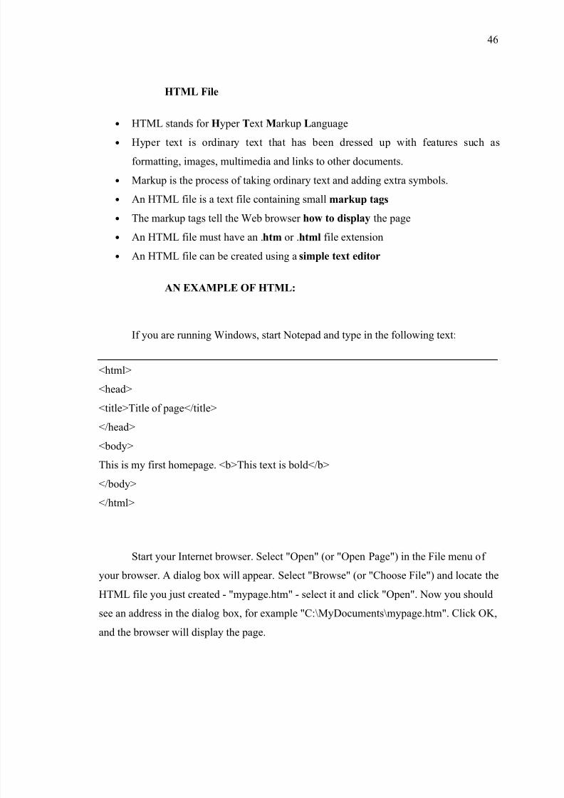
HTML File
• HTML stands for Hyper Text Markup Language
• Hyper text is ordinary text that has been dressed up with features such as
formatting, images, multimedia and links to other documents.
• Markup is the process of taking ordinary text and adding extra symbols.
• An HTML file is a text file containing small markup tags
• The markup tags tell the Web browser how to display the page
• An HTML file must have an .htm or .html file extension
• An HTML file can be created using a simple text editor
AN EXAMPLE OF HTML:
If you are running Windows, start Notepad and type in the following text:
<html>
<head>
<title>Title of page</title>
</head>
<body>
This is my first homepage. <b>This text is bold</b>
</body>
</html>
Start your Internet browser. Select "Open" (or "Open Page") in the File menu of your browser. A dialog box will appear. Select "Browse" (or "Choose File") and locate the
HTML file you just created - "mypage.htm" - select it and click "Open". Now you should
see an address in the dialog box, for example "C:\MyDocuments\mypage.htm". Click OK,
and the browser will display the page.
46

8/3/2019 Hostel New
http://slidepdf.com/reader/full/hostel-new 47/88
Example Explained:
The first tag in your HTML document is <html>. This tag tells your browser that
this is the start of an HTML document. The last tag in your document is </html>. This tag
tells your browser that this is the end of the HTML document. The text between the
<head> tag and the </head> tag is header information. Header information is not displayed
in the browser window. The text between the <title> tags is the title of your document.
The title is displayed in your browser's caption. The text between the <body> tags is thetext that will be displayed in your browser. The text between the <b> and </b> tags will be
displayed in a bold font.
HTML Tags:
• HTML tags are used to mark-up HTML elements
• HTML tags are surrounded by the two characters < and >
•
The surrounding characters are called angle brackets• HTML tags normally come in pairs like <b> and </b>
• The first tag in a pair is the start tag, the second tag is the end tag
• The text between the start and end tags is the element content
• HTML tags are not case sensitive, <b> means the same as <B>
HTML Elements:
This is an HTML element:<b>This text is bold</b>.The HTML element starts
with a start tag: <b>The content of the HTML element is: This text is boldThe HTML
47
8/3/2019 Hostel New
http://slidepdf.com/reader/full/hostel-new 48/88
element ends with an end tag: </b>.The purpose of the <b> tag is to define an HTML
element that should be displayed as bold.
HTML Tag Attributes:
• HTML tags can have attributes.
• Attributes provide additional information to an HTML element.
• Attributes always come in name/value pairs like this: name="value".
• <body>: This tag defines the body of an HTML document.<body
bgcolor="yellow"> has additional information about the background
color.
• <table>: This tag defines an HTML table. (You will learn more about HTML
tables later)
• <table border="1"> has additional information about the border around the table
• Attributes are always specified in the start tag of an HTML element.
HTML Advantages:
• HTML is the primary format used on the World Wide Web.
• HTML can display Web pages with a wide range of colors, shapes, and objects.
• HTML is so flexible, many browsers and Web applications have added their own
functionality to the base HTML protocol.
• HTML ensures consistency in style across elements that have the same meaning.
4.2 DATABASE MANAGEMENT SYSTEM
48
8/3/2019 Hostel New
http://slidepdf.com/reader/full/hostel-new 49/88
DATABASE:
A database is a collection of data, with some internal meaning design built
populated with data for a specific purpose.
CHARACTERISTICS:
1. Represents complex relationship between data.
2. Keeps control on data redundancy.
3. Enforces data access authorization.
4. Has automatic intelligent backup and recovery procedure for data.
5. Keeps a centralized data dictionary for the storage of information pertaining to
data and manipulation.
DATA MODELS:
The structure of the database is the conceptual model, collection of tools for
describing data relationship, semantics and consistency constrains.
I. Object Based models
Object-based logical model are used in describing at the conceptual and view levels
there are two of object-based models:
i. The entity relationship model: this model is model based on a Real world, which
consists of a collection of objects called entities and relationship among these.
ii. The object Oriented model: The Object oriented model is based on the
collection of objects. Methods are grouping into classes a class may be viewed as a
type definition-for-objects.
49
8/3/2019 Hostel New
http://slidepdf.com/reader/full/hostel-new 50/88
II. Records based Models:
Record based models are so named because the data is structured in fixed
format records. The three most accepted record based data models are relation,
network, and hierarchical models.
i. Relation Model: The Relational represents the data and relational ship
among data by a collection of tables, where each table has a number of
columns with unique names.
ii. Network model: Data in network model are represented by collection of
records and relationships among data are represented by links, which can be
viewed as pointers. The records in the database are organized as collection of
arbitrary graphs.
iii. Hierarchical Model: This model is similar to network model in the sensethat data and relationships among data represented by records and links,
respectively. It differs from the network model in that the records are organized
as collection of trees rather than arbitrary graphs.
RELATIONAL DATABASE MODEL:
A Relational database consists of collection of the tables, each of which is assigned
unique name. Each table contains number of columns also with unique names. Relational
is an association among several entities. The row in a table represents a relation ship
among a set of values.
50
8/3/2019 Hostel New
http://slidepdf.com/reader/full/hostel-new 51/88
TABLES:
In relational system data is organized and presented in tables. Tables are simply a
collection of related rows and columns.
ROWS:
Rows are the horizontal components of a table. They are unnamed and unordered.
This means that there is no way to specify a particular table rows by its position in a table
are accessed by data values only.
COLUMNS:
Columns are the vertical components of table. Unlike rows, columns are named and
ordered. Every table columns has a unique name within the table and add a data attributesfor it.
FIELDS:
Fields refer to the specific data values stored in a table for a particular intersection
of row and column. A field is the smallest unit of data in SQL. A null field denotes
absence of data values for that particular field.
ADVANTAGES OF RDMS:
51
8/3/2019 Hostel New
http://slidepdf.com/reader/full/hostel-new 52/88
1. Redundancy can be reduced: In a non-database system, each application has
its own private file. This often leads to considerable redundancy in stored data
with result wastage in storage space.
2. Inconsistency can be avoided: There will be some occasions on which two
entries do not agree. This is called inconsistency. It can be avoided in a database
by propagation updates.
3. Data can be shared: It means that not only the existing application can share
the data in a database but also new applications can be developed.
4. Standards can be enforced: With central control of data, certain standards like
Industrial, National, and international can be developed.
5. Security Restrictions can be applied: Having complete control of data, we can
ensure that the only means of accessing data is through proper channel.
6. Integrity can be maintained: The problem of integrity is the problem of ensuring data in the database is accurate. It can be ensured that by definition
validation procedures whenever updating operation is to be carried out.
7. Conflicting requirements can be balanced: Database can be structured to
provide an over-all service.
NORMALIZATION
NORMALIZATION theory is built around the concept of normal forms.
Relation is said to be in a particular normal form if it satisfies a certain specified set of
constraints. In a relation R attributes Y of R in functionally dependent on the attribute
of X of R if X value in R has associated with it precisely one Y-value in R at any one
52
8/3/2019 Hostel New
http://slidepdf.com/reader/full/hostel-new 53/88
time. Attribute Y is functionally dependent on attributes X if it is functionally
dependent on any proper set of X.
• A relation R is said to be in First Normal Form (1NF) if and only if all underlying
domain contain atomic values only.
• A relation R is said to be in Second Normal Form (2NF) if and only if it is in 1NF
and every non key attribute is fully dependent on the primary key.
• A relation R is said to be in Third Normal Form (3NF) if and only if it is in 2NF
and every non key attribute is fully dependent on the primary key.
• A relation R is in Boyce Codd Normal Form (BCNF) if and only if it is in every
determinant is an attribute in which some other function is fully functionally
dependent.
• A relation R is in Forth Normal Form (4NF) if and only if whenever there exists an
multivolume dependence in R day A→B, then all attributes of R is also
functionally dependent on A.
• A relation R is in Fifth Normal Form (5NF) if and only if every join dependency in
R is implied by the candidate keys of R.
4.3 MYSQL
MySQL
MySQL, the most popular Open Source SQL database management system, is
developed, distributed, and supported by MySQL AB.
• MySQL is a database management system.
A database is a structured collection of data. It may be anything from a simple
shopping list to a picture gallery or the vast amounts of information in a corporate
network. To add, access, and process data stored in a computer database, you need
53

8/3/2019 Hostel New
http://slidepdf.com/reader/full/hostel-new 54/88
a database management system such as MySQL Server. Since computers are very
good at handling large amounts of data, database management systems play a
central role in computing, as standalone utilities, or as parts of other applications.
• MySQL is a relational database management system.
A relational database stores data in separate tables rather than putting all the data
in one big storeroom. This adds speed and flexibility. The SQL part of “MySQL”
stands for “Structured Query Language.” SQL is the most common standardized
language used to access databases and is defined by the ANSI/ISO SQL Standard.
• MySQL software is Open Source.
Open Source means that it is possible for anyone to use and modify the software.
Anybody can download the MySQL software from the Internet and use it without
paying anything. If you wish, you may study the source code and change it to suit
your needs.
• The MySQL Database Server is very fast, reliable, and easy to use.
MySQL Server was originally developed to handle large databases much faster
than existing solutions and has been successfully used in highly demanding
production environments for several years.
• MySQL Server works in client/server or embedded systems.
The MySQL Database Software is a client/server system that consists of a multi-
threaded SQL server that supports different back ends. We also provide MySQL
Server as an embedded multi-threaded library that you can link into your
application to get a smaller, faster, easier-to-manage standalone product.
54
8/3/2019 Hostel New
http://slidepdf.com/reader/full/hostel-new 55/88
The Main Features of MySQL:
• Written in C and C++.
• Tested with a broad range of different compilers.
• Works on many different platforms.
• The MySQL Server design is multi-layered with independent modules.
• Fully multi-threaded using kernel threads. It can easily use multiple CPUs if they
are available.
• Relatively easy to add other storage engines. This is useful if you want to provide
an SQL interface for an in-house database.
• A very fast thread-based memory allocation system.
• In-memory hash tables, which are used as temporary tables.
• The MySQL code is tested with Purify (a commercial memory leakage detector).
• The server is available as a separate program for use in a client/server networked
environment. It is also available as a library that can be embedded (linked) into
standalone applications. Such applications can be used in isolation or in
environments where no network is available.
Distinguishing features:
The following features are implemented by MySQL but not by some other RDBMSes:
• Multiple storage engines, allowing you to choose the one which is most effective
for each table in the application (in MySQL 5.0, storage engines must be compiled
in. In MySQL 5.1, storage engines can be dynamically loaded at Run time.
• Native storage engines (MyISAM, Falcon, Merge, Memory (heap), Federated,
Archive, CSV, Blackhole, Cluster, BDB, EXAMPLE)
• Partner-developed storage engines (InnoDB, solidDB, NitroEDB, BrightHouse)
55
8/3/2019 Hostel New
http://slidepdf.com/reader/full/hostel-new 56/88
• Community-developed storage engines (memcached, httpd, PBXT)
DATATYPES:
• Many data types: signed/unsigned integers 1, 2, 3, 4, and 8 bytes long, FLOAT,
DOUBLE, CHAR , VARCHAR , TEXT, BLOB, DATE, TIME, DATETIME, TIMESTAMP,
YEAR , SET, ENUM.
STATEMENTS AND FUNCTIONS:
• Full operator and function support in the SELECT list and WHERE clause of
queries.
• For example:
• mysql> SELECT CONCAT(first_name, ' ', last_name)
•
-> FROM citizen• -> WHERE income/dependents > 10000 AND age > 30;
• Full support for SQL GROUP BY and ORDER BY clauses. Support for group
functions (COUNT(), COUNT(DISTINCT ...), AVG(), STD(), SUM(), MAX(),
MIN(), and GROUP_CONCAT()).
• Support for LEFT OUTER JOIN and RIGHT OUTER JOIN with both standard
SQL and ODBC syntax.
• DELETE, INSERT, REPLACE, and UPDATE return the number of rows that
were changed (affected). It is possible to return the number of rows matched
instead by setting a flag when connecting to the server.
• The MySQL-specific SHOW statement can be used to retrieve information about
databases, storage engines, tables, and indexes.
56
8/3/2019 Hostel New
http://slidepdf.com/reader/full/hostel-new 57/88
• The EXPLAIN statement can be used to determine how the optimizer resolves a
query.
SECURITY:
• A privilege and password system that is very flexible and secure, and that allows
host-based verification.
• Passwords are secure because all password traffic is encrypted when you connect
to a server.
SCALABILITY AND LIMITS:
• Handles large databases. We use MySQL Server with databases that contain 50
million records. We also know of users who use MySQL Server with 60,000 tables
and about 5,000,000,000 rows.
CONNECTIVITY:
• Clients can connect to MySQL Server using several protocols:
o Clients can connect using TCP/IP sockets on any platform.
o On UNIX systems, clients can connect using UNIX domain socket files.
•
MySQL client programs can be written in many languages. A client library writtenin C is available for clients written in C or C++, or for any language that provides
C bindings.
• APIs for C, C++, Eiffel, Java, Perl, PHP, Python, Ruby, and Tcl are available,
allowing MySQL clients to be written in many languages.
57
8/3/2019 Hostel New
http://slidepdf.com/reader/full/hostel-new 58/88
• The Connector/ODBC (MyODBC) interface provides MySQL support for client
programs that use ODBC (Open Database Connectivity) connections. The
Connector/J interface provides MySQL support for Java client programs that use
JDBC connections. Clients can be run on Windows or UNIX. Connector/J source
is available.
MySQL Connector/NET enables developers to easily create .NET applications that require
secure, high-performance data connectivity with MySQL aware tools. Developers can
build applications using their choice of .NET languages.
• The MySQL® database has become the world's most popular open source database
because of its consistent fast performance, high reliability and ease of use. It's used
on every continent (even Antarctica!) by individual Web developers as well as
many of the world's largest and fastest-growing organizations to save time and
money powering their high-volume Web sites, business-critical systems and
packaged software -- including industry leaders such as Yahoo!, Alcatel-Lucent,
Google, Nokia, YouTube, and Zappos.com.
• Not only is MySQL the world's most popular open source database, it's also
become the database of choice for a new generation of applications built on the
LAMP stack (Linux, Apache, MySQL, PHP / Perl / Python.) MySQL runs on more
than 20 platforms including Linux, Windows, OS/X, HP-UX, AIX, Netware,
giving you the kind of flexibility that puts you in control.
• Whether you're new to database technology or an experienced developer or DBA,
MySQL offers a comprehensive range of certified software, support, training and
consulting to make you successful.
4.4 PHP
58
8/3/2019 Hostel New
http://slidepdf.com/reader/full/hostel-new 59/88
PHP INTRODUCTION
• PHP stands for PHP: Hypertext Preprocessor
• PHP is a server-side scripting language, like ASP
• PHP scripts are executed on the server
• PHP supports many databases (MySQL, Informix, Oracle, Sybase, Solid, Generic
ODBC, etc.)
• PHP is an open source software (OSS)
• PHP is free to download and use
• PHP is a reflective programming language originally designed for producing
dynamic web pages.
PHP File
• PHP files may contain text, HTML tags and scripts
• PHP files are returned to the browser as plain HTML
• PHP files have a file extension of ".php", ".php3", or ".phtml"
PHP Purpose
• PHP runs on different platforms (Windows, Linux, Unix, etc.)
• PHP is compatible with almost all servers used today (Apache, IIS, etc.)
• PHP is FREE to download from the official PHP resource: www.php.net
• PHP is easy to learn and runs efficiently on the server side.
59
8/3/2019 Hostel New
http://slidepdf.com/reader/full/hostel-new 60/88
Features of PHP:
• Robust support for object oriented programming
• The php data objects extension, which defines a lightweight and consistent
interface for accessing databases.
• Better support for mysql through a completely rewritten extension.
• Error handling through exception
Sample PHP Code:
Copy the code paste it on you account, and save it as info.php4
.<?
php
Phpinfo();?>
It will output information about the current state of PHP, which information of PHP
compilation options and extensions, the PHP version, server information and environment,
the PHP environment, OS version information, paths, master and local values of
configuration options, HTTP headers, and the PHP license.
Comments in PHP:
In PHP, we use // to make a single-line comment or /* and */ to make a large
comment block.
<html>
60
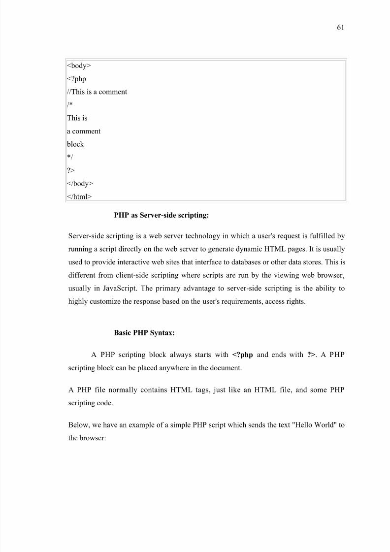
8/3/2019 Hostel New
http://slidepdf.com/reader/full/hostel-new 61/88
<body>
<?php
//This is a comment
/*
This is
a comment
block
*/
?>
</body>
</html>
PHP as Server-side scripting:
Server-side scripting is a web server technology in which a user's request is fulfilled by
running a script directly on the web server to generate dynamic HTML pages. It is usually
used to provide interactive web sites that interface to databases or other data stores. This is
different from client-side scripting where scripts are run by the viewing web browser,
usually in JavaScript. The primary advantage to server-side scripting is the ability tohighly customize the response based on the user's requirements, access rights.
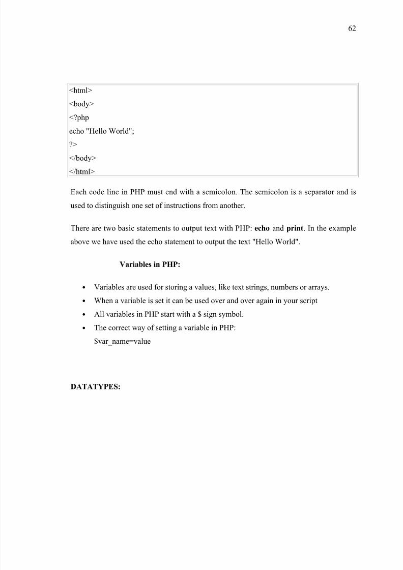
Basic PHP Syntax:
A PHP scripting block always starts with <?php and ends with ?>. A PHP
scripting block can be placed anywhere in the document.
A PHP file normally contains HTML tags, just like an HTML file, and some PHP
scripting code.
Below, we have an example of a simple PHP script which sends the text "Hello World" to
the browser:
61
8/3/2019 Hostel New
http://slidepdf.com/reader/full/hostel-new 62/88
<html>
<body>
<?php
echo "Hello World";
?>
</body>
</html>
Each code line in PHP must end with a semicolon. The semicolon is a separator and is
used to distinguish one set of instructions from another.
There are two basic statements to output text with PHP: echo and print. In the example
above we have used the echo statement to output the text "Hello World".
Variables in PHP:
• Variables are used for storing a values, like text strings, numbers or arrays.
• When a variable is set it can be used over and over again in your script
• All variables in PHP start with a $ sign symbol.
• The correct way of setting a variable in PHP:
$var_name=value
DATATYPES:
62
8/3/2019 Hostel New
http://slidepdf.com/reader/full/hostel-new 63/88
PHP stores whole numbers in a platform-dependent range. This range is typically that of
32-bit signed integers. Integer variables can be assigned using decimal (positive and
negative), octal and hexadecimal notations. Real numbers are also stored in a platform-
specific range.
PHP has a native Boolean type, named "boolean", similar to the native Boolean types in
Java and C++. Using the Boolean type conversion rules, non-zero values are interpreted as
true and zero as false, as in Perl.
There are eight data types in PHP:
1. Integer
2. Double
3. Boolean
4. String
5. Object
6. Array
7. Null
8. Resource
The null data type represents a variable that has no value. The only value in the null data
type is NULL.
Resources:
Libraries:
PHP includes a large number of free and open source libraries with the core build.
PHP is a fundamentally Internet-aware system with modules built in for accessing FTP
servers, many database servers, embedded SQL libraries such as embedded MySQL and
SQLite, LDAP servers, and others. Many functions familiar to C programmers such as
those in the ‘stdio’ family are available in the standard PHP build.
63
8/3/2019 Hostel New
http://slidepdf.com/reader/full/hostel-new 64/88
Extension:
PHP allows developers to write extensions in ‘C’ to add functionality to the PHP
language. These can then be compiled into PHP or loaded dynamically at runtime.
Debuggers and profilers:
Debuggers and profilers allow developers to analyze running PHP code for
potential and noted software bugs and bottlenecks. Examples of such software for PHP
include APD and Xdebug.
The Advantages of PHP:
• PHP is one of the most popular server side scripting languages running today. It is
used for creating dynamic webpages that interact with the user offering customized
information.
• PHP offers many advantages; it is fast, stable, secure, easy to use and open source
(free).
4.5 DATABASE TABLES
CREATE TABLE USERS(USERNAME VARCHAR(20) NOT NULL,
PASSWORD VARCHAR(20) NOT NULL,
PRIMARY KEY(USERNAME,PASSWORD));
64

8/3/2019 Hostel New
http://slidepdf.com/reader/full/hostel-new 65/88
CREATE TABLE STUDENT(
SID VARCHAR(30) NOT NULL,
NAME VARCHAR(20),
DOB DATE,
COURSE VARCHAR(10),
BRANCH VARCHAR(10),
STU_YEAR CHAR(3),
ADMNO VARCHAR(15),
FNAME VARCHAR(20),
MNAME VARCHAR(20),
PHNO BIGINT(20),
ADDR VARCHAR(100),
DOJ DATE,
DOL DATE DEFAULT '0000-00-00',
YEAR INT(5) NOT NULL,
EATING VARCHAR(10),
GNAME VARCHAR(20),
GADDR VARCHAR(100),GPHONE BIGINT(20),
RNO INT(5),
MILK VARCHAR(8),
SNO INT(8) NOT NULL AUTO_INCREMENT,
PRIMARY KEY(YEAR,SNO),
FOREIGN KEY(RNO) REFERENCES ROOMS(RNO) )ENGINE=MYISAM;
CREATE TABLE EMPLOYEE(
EID VARCHAR(30),
NAME VARCHAR(20),
ADDR VARCHAR(100),
65

8/3/2019 Hostel New
http://slidepdf.com/reader/full/hostel-new 66/88
PHNO BIGINT (20),
DEPT VARCHAR(15),
CADER VARCHAR(15),
DOJ DATE,
YEAR INT(5) NOT NULL,
DOL DATE DEFAULT '0000-00-00',
LSTATUS VARCHAR(15),
SALARY DOUBLE(12,2),
RNO INT(5),
MILK VARCHAR(8),
CONCESSION DOUBLE(3,2),
SNO INT(8) NOT NULL AUTO_INCREMENT,
EATING VARCHAR(10),
PRIMARY KEY(YEAR,SNO),
FOREIGN KEY(RNO) REFERENCES ROOMS(RNO))ENGINE=MYISAM;
CREATE TABLE ROOMS(
ROOMNO INT(5) NOT NULL,TYPE VARCHAR(10),
YEAR VARCHAR(4),
SPECIFY VARCHAR(15),
PRIMARY KEY(ROOMNO));
CREATE TABLE ROOMWISE(
ROOMNO INT(5) NOT NULL,
ITEM VARCHAR(15) NOT NULL,
NUM INT(5),
PRIMARY KEY(ROOMNO,ITEM));
66
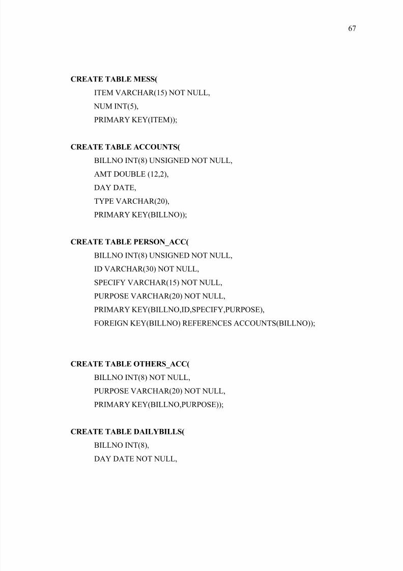
8/3/2019 Hostel New
http://slidepdf.com/reader/full/hostel-new 67/88
CREATE TABLE MESS(
ITEM VARCHAR(15) NOT NULL,
NUM INT(5),
PRIMARY KEY(ITEM));
CREATE TABLE ACCOUNTS(
BILLNO INT(8) UNSIGNED NOT NULL,
AMT DOUBLE (12,2),
DAY DATE,
TYPE VARCHAR(20),
PRIMARY KEY(BILLNO));
CREATE TABLE PERSON_ACC(
BILLNO INT(8) UNSIGNED NOT NULL,
ID VARCHAR(30) NOT NULL,
SPECIFY VARCHAR(15) NOT NULL,
PURPOSE VARCHAR(20) NOT NULL,PRIMARY KEY(BILLNO,ID,SPECIFY,PURPOSE),
FOREIGN KEY(BILLNO) REFERENCES ACCOUNTS(BILLNO));
CREATE TABLE OTHERS_ACC(
BILLNO INT(8) NOT NULL,
PURPOSE VARCHAR(20) NOT NULL,
PRIMARY KEY(BILLNO,PURPOSE));
CREATE TABLE DAILYBILLS(
BILLNO INT(8),
DAY DATE NOT NULL,
67
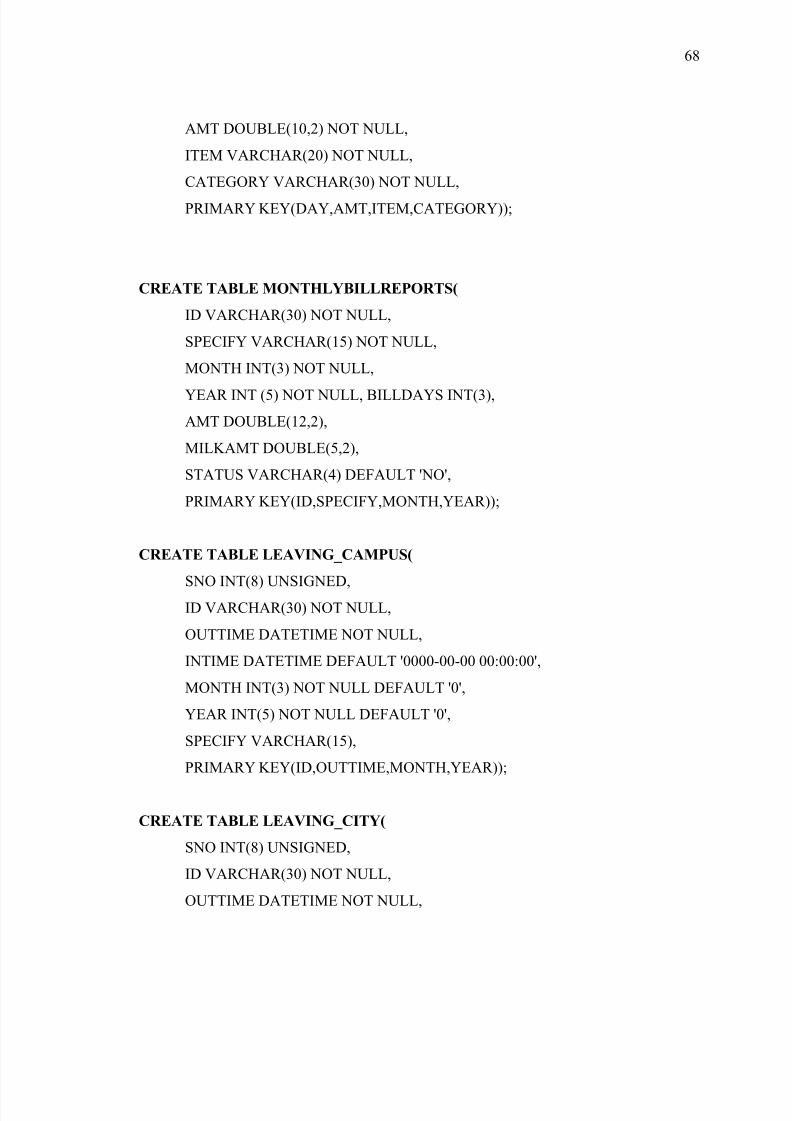
8/3/2019 Hostel New
http://slidepdf.com/reader/full/hostel-new 68/88
AMT DOUBLE(10,2) NOT NULL,
ITEM VARCHAR(20) NOT NULL,
CATEGORY VARCHAR(30) NOT NULL,
PRIMARY KEY(DAY,AMT,ITEM,CATEGORY));
CREATE TABLE MONTHLYBILLREPORTS(
ID VARCHAR(30) NOT NULL,
SPECIFY VARCHAR(15) NOT NULL,
MONTH INT(3) NOT NULL,
YEAR INT (5) NOT NULL, BILLDAYS INT(3),
AMT DOUBLE(12,2),
MILKAMT DOUBLE(5,2),
STATUS VARCHAR(4) DEFAULT 'NO',
PRIMARY KEY(ID,SPECIFY,MONTH,YEAR));
CREATE TABLE LEAVING_CAMPUS(
SNO INT(8) UNSIGNED,ID VARCHAR(30) NOT NULL,
OUTTIME DATETIME NOT NULL,
INTIME DATETIME DEFAULT '0000-00-00 00:00:00',
MONTH INT(3) NOT NULL DEFAULT '0',
YEAR INT(5) NOT NULL DEFAULT '0',
SPECIFY VARCHAR(15),
PRIMARY KEY(ID,OUTTIME,MONTH,YEAR));
CREATE TABLE LEAVING_CITY(
SNO INT(8) UNSIGNED,
ID VARCHAR(30) NOT NULL,
OUTTIME DATETIME NOT NULL,
68

8/3/2019 Hostel New
http://slidepdf.com/reader/full/hostel-new 69/88
INTIME DATETIME DEFAULT '0000-00-00 00:00:00',
DAYS INT(3),
TYPE VARCHAR(25),
REMISSION INT(3),
MONTH INT(3) NOT NULL,
YEAR INT(5) NOT NULL,
SPECIFY VARCHAR(15),
PRIMARY KEY(ID,OUTTIME,MONTH,YEAR));
CREATE TABLE MEDICINES(
NAME VARCHAR(20) NOT NULL,
MFG DATE,
EXP DATE,
DAY DATE NOT NULL,
USG VARCHAR(20),
QTY INT(5),
PRIMARY KEY(NAME,DAY));
CREATE TABLE MEDICINES(
NAME VARCHAR(20) NOT NULL,
MFG DATE,
EXP DATE,
DAY DATE NOT NULL,
USG VARCHAR(20),
QTY INT(5),
PRIMARY KEY(NAME,DAY));
4.6 HTML & PHP SAMPLE CODES
69

8/3/2019 Hostel New
http://slidepdf.com/reader/full/hostel-new 70/88
Frontpage_html.php:
<html>
<title>
frontpage
</title>
<body bgcolor="steelblue">
<center>
<div height="170">
<font color="white">
<h1><img src="logo.jpg" alt="LOGO" width="130" height="130" align="left">PRASAD
V.POTLURI SIDDHARTHA INSTITUTE OF TECHNOLOGY </h2>
<h2 align="center"><strong>HOSTEL </strong></h3>
</div>
<br><br>
<img src="college.jpg" height="500" width="700">
<br><br>
<a href="login_html.php"><img src="login.png"border="0"></a>
<a href="student_search_html.php"><img src="students.png" border="0"></a>
<a href="employee_search_html.php"><img src="employee.png" border="0"></a>
<a href="credits_html.php"><img src="credits.png" border="0"></a>
</font>
<br><br><br>
<iframesrc="http://www.facebook.com/plugins/like.php?href=<?phpecho
urlencode('http://'.$_SERVER['SERVER_NAME'].$_SERVER['REQUEST_URI']) ?
>&layout=standard&show_faces=true&width=450&action=recomme
70
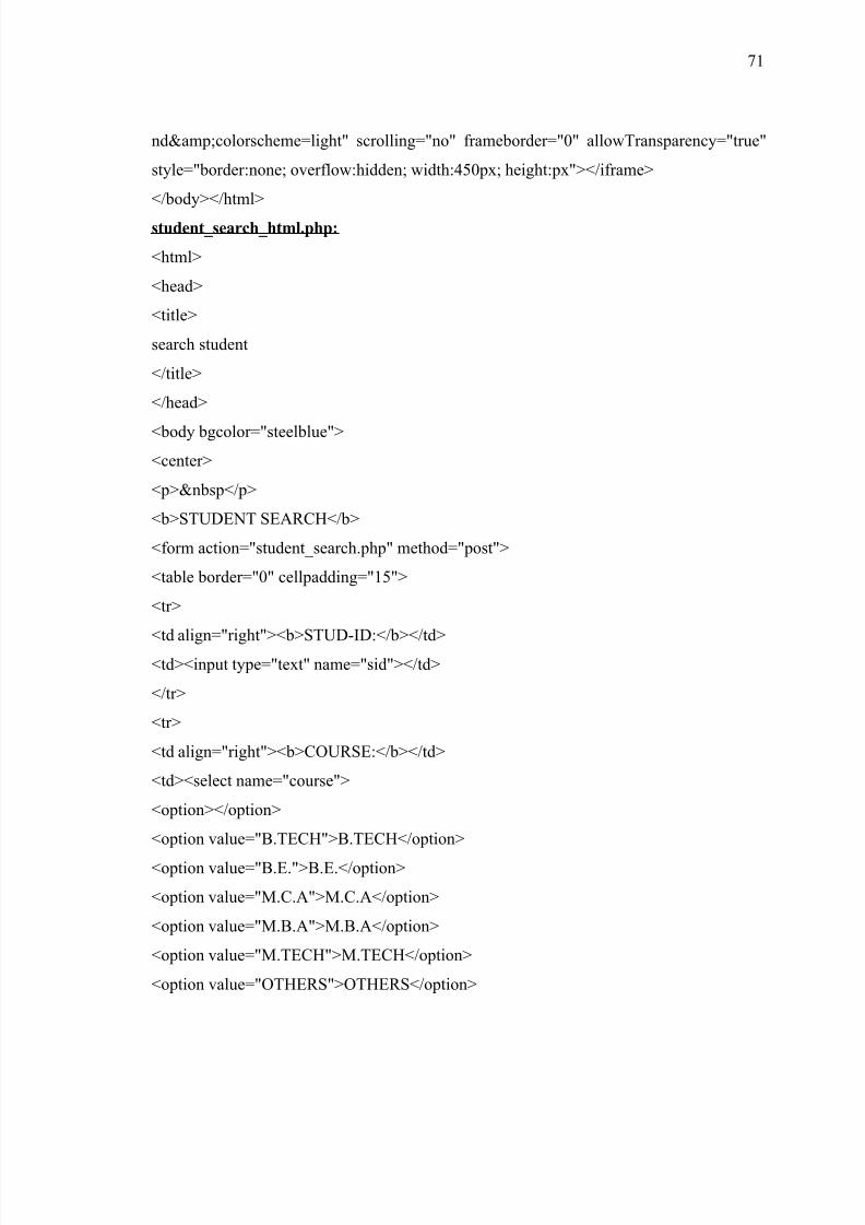
8/3/2019 Hostel New
http://slidepdf.com/reader/full/hostel-new 71/88
nd&colorscheme=light" scrolling="no" frameborder="0" allowTransparency="true"
style="border:none; overflow:hidden; width:450px; height:px"></iframe>
</body></html>
student_search_html.php:
<html>
<head>
<title>
search student
</title>
</head>
<body bgcolor="steelblue">
<center>
<p> </p>
<b>STUDENT SEARCH</b>
<form action="student_search.php" method="post">
<table border="0" cellpadding="15">
<tr>
<td align="right"><b>STUD-ID:</b></td><td><input type="text" name="sid"></td>
</tr>
<tr>
<td align="right"><b>COURSE:</b></td>
<td><select name="course">
<option></option>
<option value="B.TECH">B.TECH</option>
<option value="B.E.">B.E.</option>
<option value="M.C.A">M.C.A</option>
<option value="M.B.A">M.B.A</option>
<option value="M.TECH">M.TECH</option>
<option value="OTHERS">OTHERS</option>
71
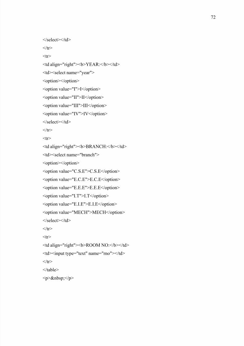
8/3/2019 Hostel New
http://slidepdf.com/reader/full/hostel-new 72/88
</select></td>
</tr>
<tr>
<td align="right"><b>YEAR:</b></td>
<td><select name="year">
<option></option>
<option value="I">I</option>
<option value="II">II</option>
<option value="III">III</option>
<option value="IV">IV</option>
</select></td>
</tr>
<tr>
<td align="right"><b>BRANCH:</b></td>
<td><select name="branch">
<option></option>
<option value="C.S.E">C.S.E</option>
<option value="E.C.E">E.C.E</option><option value="E.E.E">E.E.E</option>
<option value="I.T">I.T</option>
<option value="E.I.E">E.I.E</option>
<option value="MECH">MECH</option>
</select></td>
</tr>
<tr>
<td align="right"><b>ROOM NO:</b></td>
<td><input type="text" name="rno"></td>
</tr>
</table>
<p> </p>
72
8/3/2019 Hostel New
http://slidepdf.com/reader/full/hostel-new 73/88
<input type="submit" value="SUBMIT">
</form>
</center>
</body>
</html>
CHAPTER 5
SYSTEM TESTING
Testing is the process of detection errors. Testing performs a very quality role for
assurance and for ensuring the ability of software. The results of testing are used latter on
during maintenance also.
5.1 TESTING OBJECTIVES
The main objective of testing is to uncover a host error, systematically and the
minimum effort and time starting formally, we can say
1. Test is the process executing a program with the intent of finding an error.
2. A successful test is one that uncovers as ad yet undiscovered error.
3. A good test case is one that has a high probability of finding errors, if it exits.
73
8/3/2019 Hostel New
http://slidepdf.com/reader/full/hostel-new 74/88
5.1.1 WHITE BOX TESTING
•
This is unit testing method where is unit will be taken at a time and testedthoroughly at a statement level to find the maximum level errors.
• We have tested step wise every piece of code ,taking care that every statement in
the code
• Is executed at least once.
• The white box testing is also called glass box testing.
BLACK BOX TESTING:
This testing method a models a single unit and checks the unit at interface and
communication with other models rather getting g into details levels. Here the model will
be treated as a black box that take input and generates the output. Output of given input
combinations are forwarded to other models.
5.1.3 UNIT TESTING
Unit testing focuses verification effort on the smallest unit of software that is the
model using the detailed design and the processes specifications testing is done to uncover
errors within the boundary of the model all model must be successful in the unit test
before the start of the integration testing.
In our project s unit testing involves checking each future specified in the
component a component performs only small part of the functionality on the system and
relies on cooperating with other part of the system.
74
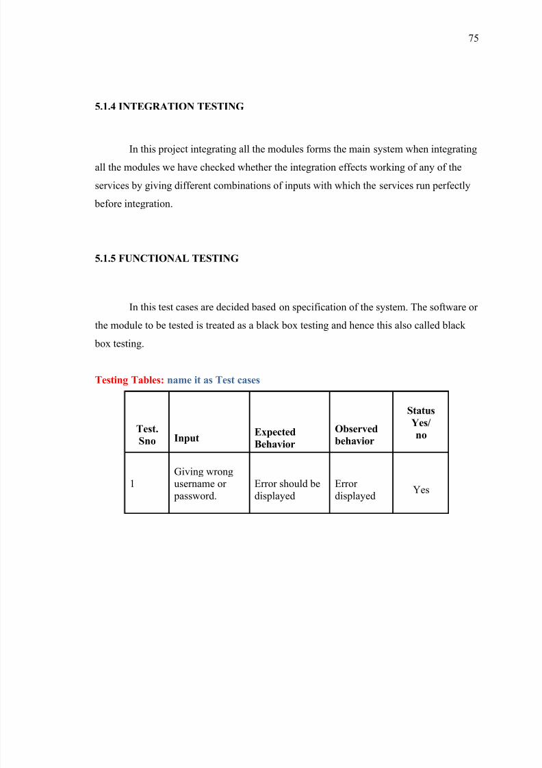
8/3/2019 Hostel New
http://slidepdf.com/reader/full/hostel-new 75/88
5.1.4 INTEGRATION TESTING
In this project integrating all the modules forms the main system when integrating
all the modules we have checked whether the integration effects working of any of the
services by giving different combinations of inputs with which the services run perfectly
before integration.
5.1.5 FUNCTIONAL TESTING
In this test cases are decided based on specification of the system. The software or
the module to be tested is treated as a black box testing and hence this also called black
box testing.
Testing Tables: name it as Test cases
Test.
Sno InputExpected
Behavior
Observed
behavior
Status
Yes/
no
1Giving wrongusername or password.
Error should bedisplayed
Error displayed
Yes
75
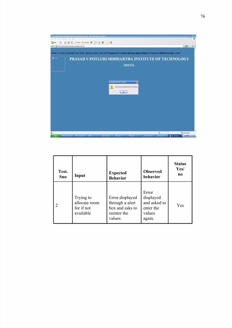
8/3/2019 Hostel New
http://slidepdf.com/reader/full/hostel-new 76/88
Test.Sno Input Expected
Behavior
Observedbehavior
Status
Yes/
no
2
Trying toallocate roomfor if notavailable
Error displayedthrough a alert box and asks toreenter thevalues.
Error displayedand asked toenter thevaluesagain.
Yes
76
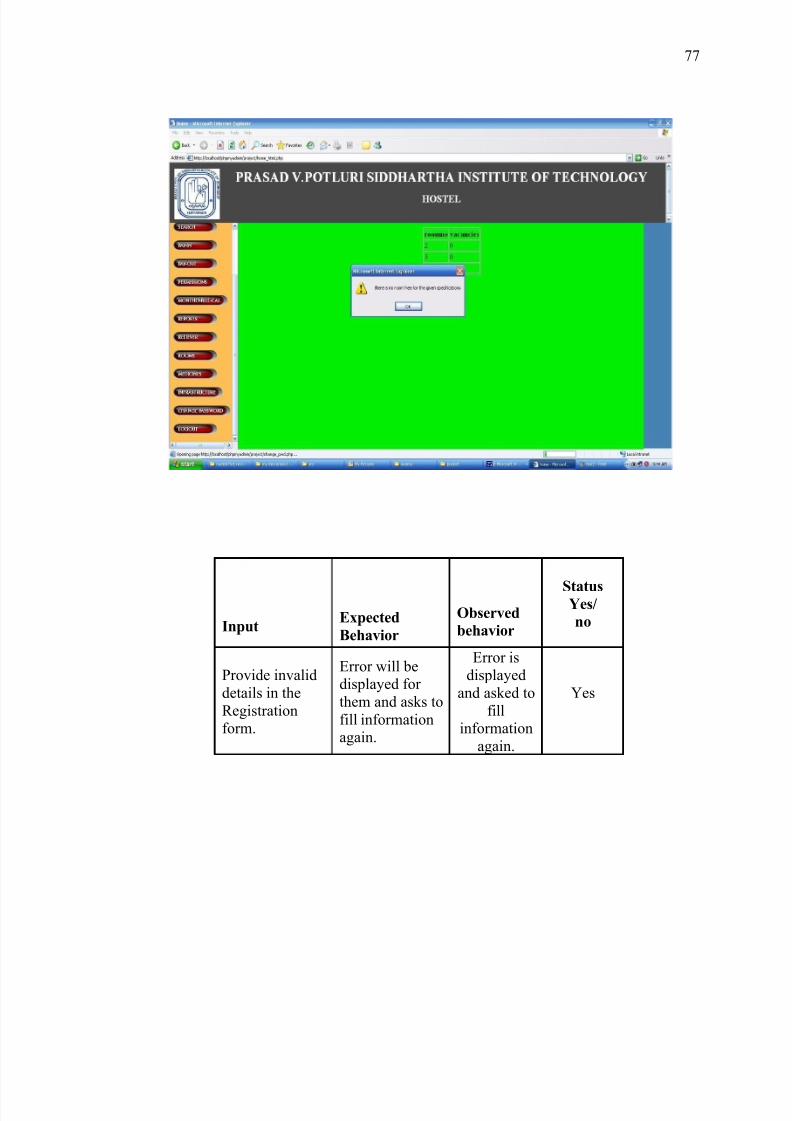
8/3/2019 Hostel New
http://slidepdf.com/reader/full/hostel-new 77/88
InputExpected
Behavior
Observed
behavior
StatusYes/
no
Provide invaliddetails in theRegistrationform.
Error will bedisplayed for them and asks tofill informationagain.
Error isdisplayed
and asked tofill
informationagain.
Yes
77
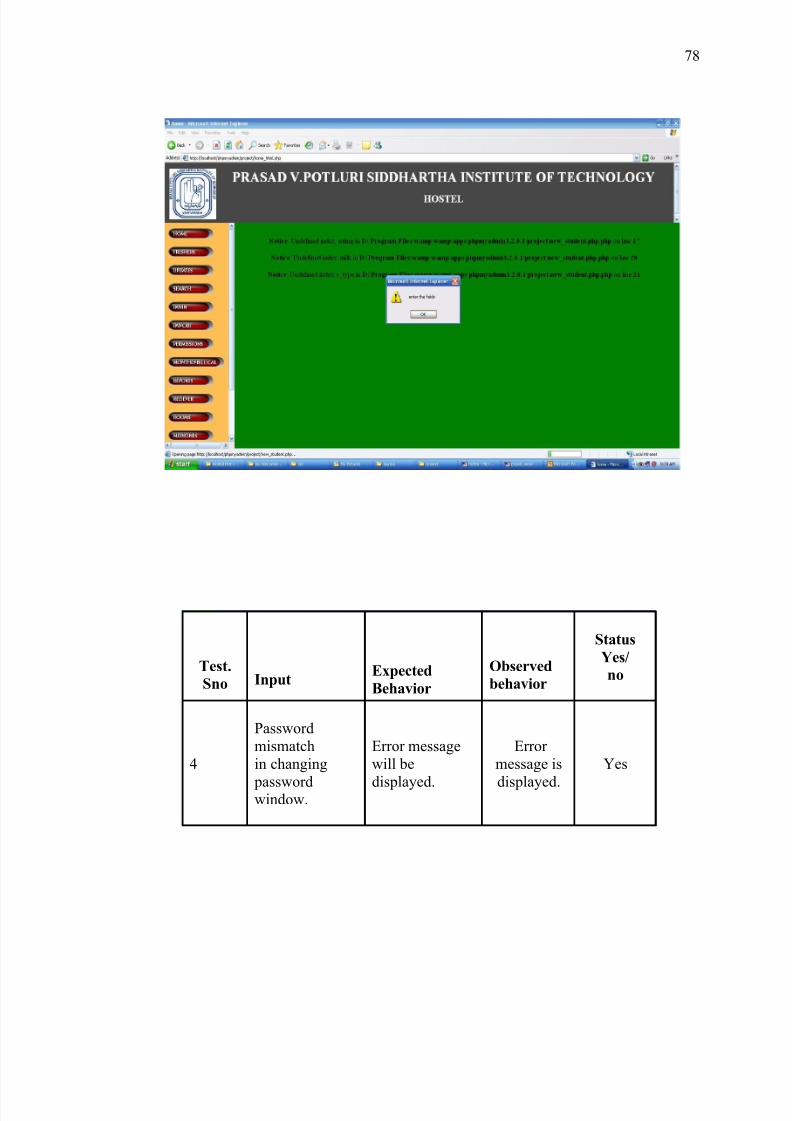
8/3/2019 Hostel New
http://slidepdf.com/reader/full/hostel-new 78/88
Test.
Sno InputExpected
Behavior
Observed
behavior
Status
Yes/
no
4
Passwordmismatchin changing
passwordwindow.
Error messagewill be
displayed.
Error message is
displayed.
Yes
78
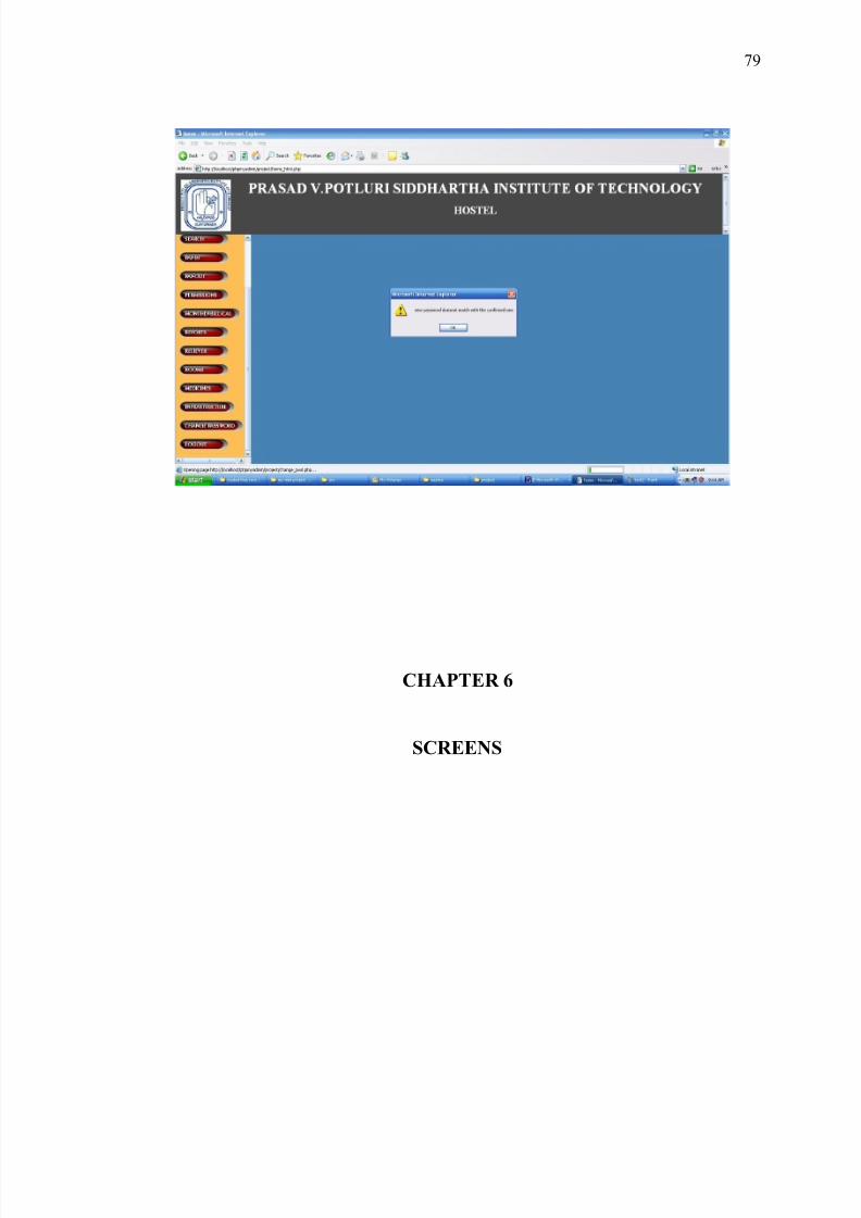
8/3/2019 Hostel New
http://slidepdf.com/reader/full/hostel-new 79/88
CHAPTER 6
SCREENS
79
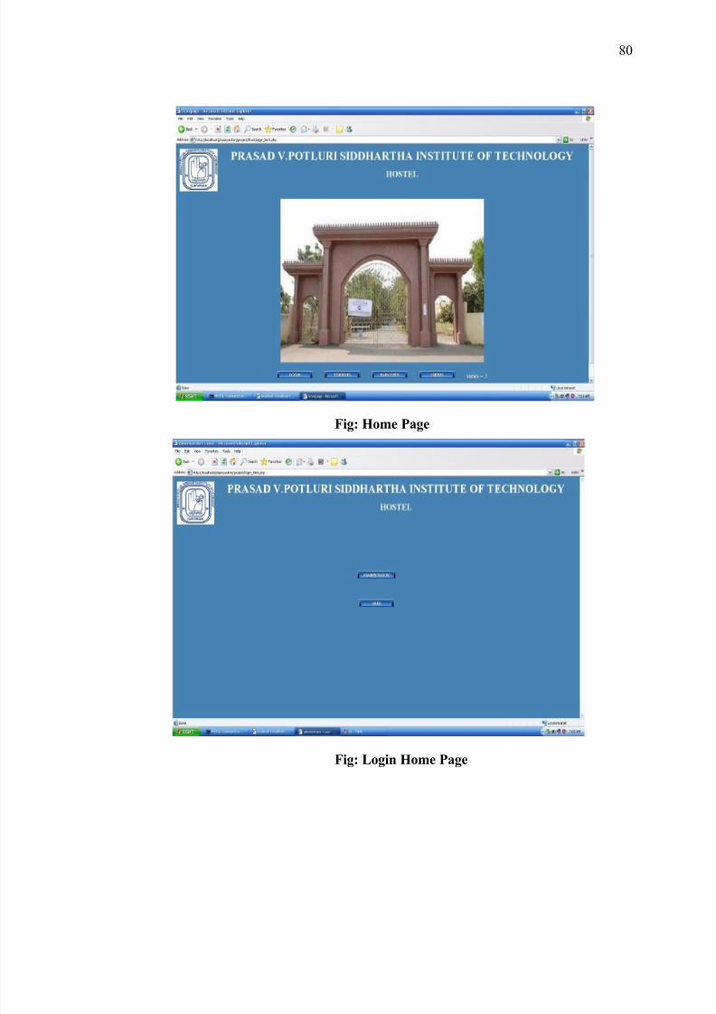
8/3/2019 Hostel New
http://slidepdf.com/reader/full/hostel-new 80/88
Fig: Home Page
Fig: Login Home Page
80
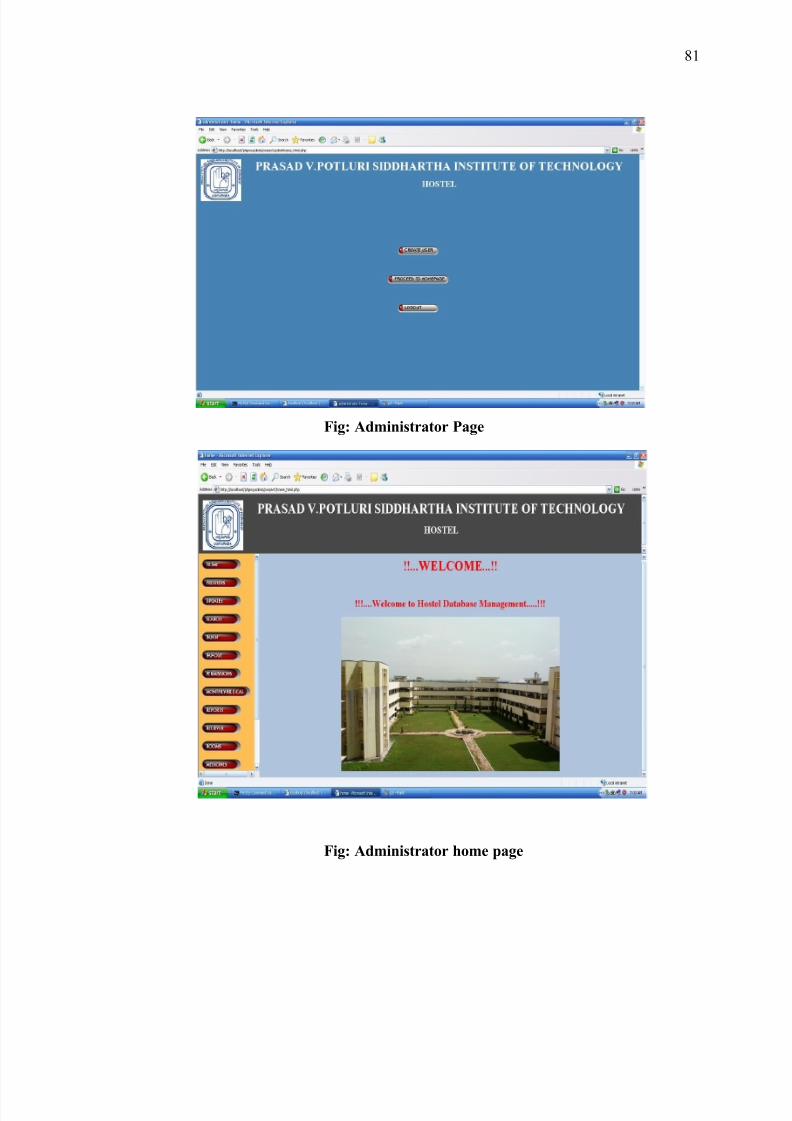
8/3/2019 Hostel New
http://slidepdf.com/reader/full/hostel-new 81/88
Fig: Administrator Page
Fig: Administrator home page
81
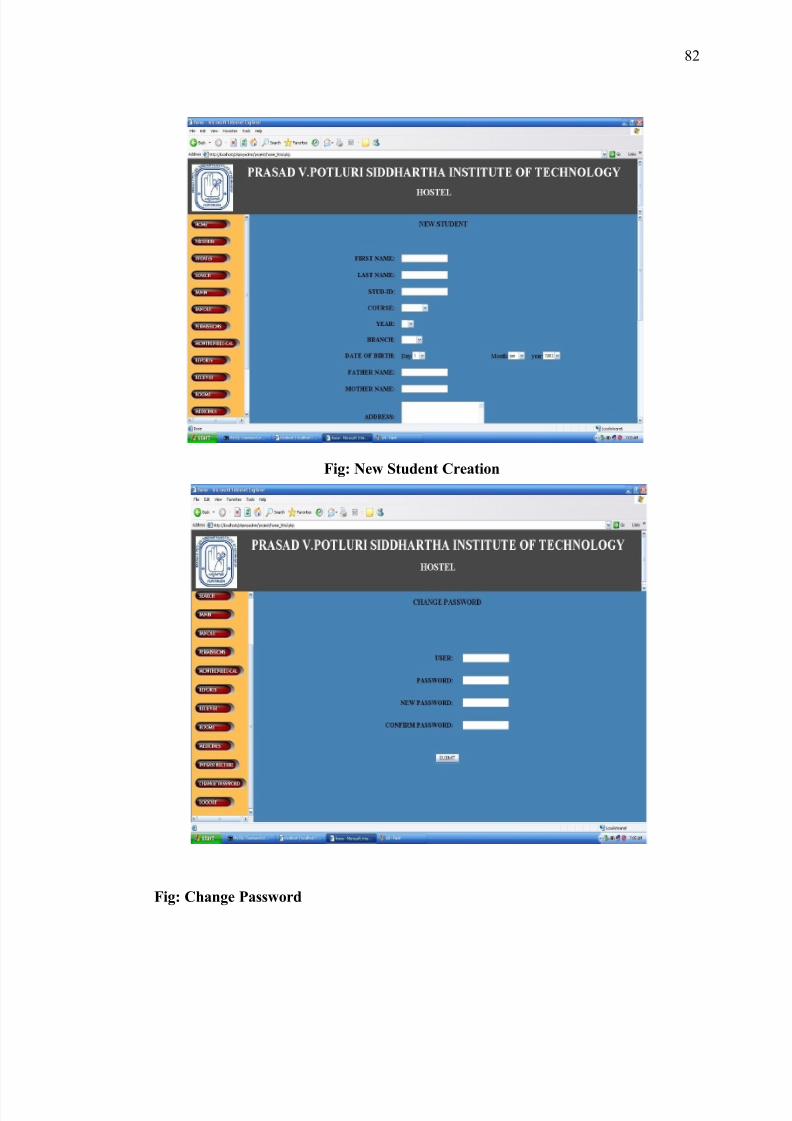
8/3/2019 Hostel New
http://slidepdf.com/reader/full/hostel-new 82/88
Fig: New Student Creation
Fig: Change Password
82
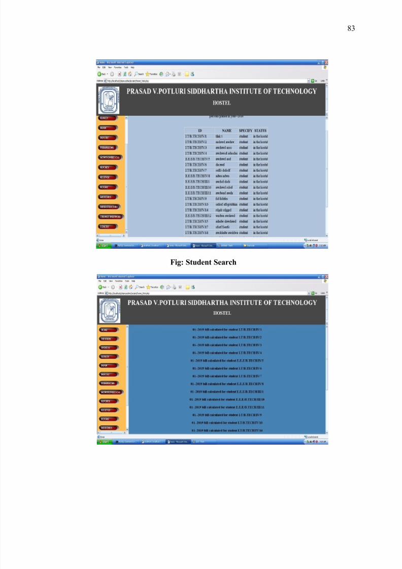
8/3/2019 Hostel New
http://slidepdf.com/reader/full/hostel-new 83/88
Fig: Student Search
83
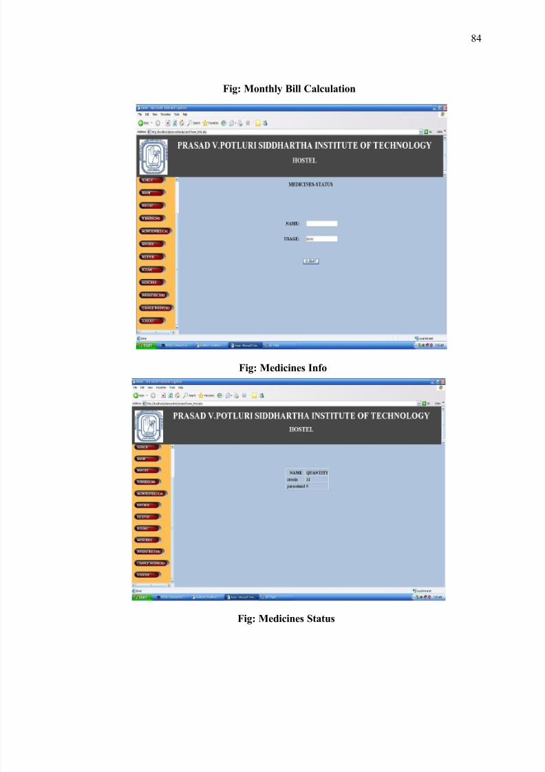
8/3/2019 Hostel New
http://slidepdf.com/reader/full/hostel-new 84/88
Fig: Monthly Bill Calculation
Fig: Medicines Info
Fig: Medicines Status
84
8/3/2019 Hostel New
http://slidepdf.com/reader/full/hostel-new 85/88
DOCUMENTATION
OPERATING THE PACKAGE
Operating is the stage in the project where the theoretical design is turned into a
working system and is giving confidence on the new system for the users that it will work
efficiently and effectively. It involves careful planning, investigation of the current system
and its constraints on implementation, design of methods to achieve the change over, an
evaluation of change over methods. Apart from planning major task of preparing the
implementation are education and training of users. The implementation process begins
with preparing a plan for the implementation of the system. According to this plan, the
activities are to be carried out, discussions made regarding the equipment and resources
and the additional equipment has to be acquired to implement the new system. In network
backup system no additional resources are needed.
Implementation is the final and the most important phase. The most critical stage
in achieving a successful new system is giving the users confidence that the new system
will work and be effective. The system can be implemented only after thorough testing is
done and if it is found to be working according to the specification. This method also
offers the greatest security since the old system can take over if the errors are found or
inability to handle certain type of transactions while using the new system.
USER TRAINING
After the system is implemented successfully, training of the user is one of the
most important subtasks of the developer. For this purpose user manuals are prepared and
handled over to the user to operate the developed system. Thus the users are trained to
85
8/3/2019 Hostel New
http://slidepdf.com/reader/full/hostel-new 86/88
operate the developed system. Both the hardware and software securities are made to run
the developed systems successfully in future. In order to put new application system into
use, the following activities were taken care of:
· Preparation of user and system documentation
. Conducting user training with demo and hands on
· Test run for some period to ensure smooth switching over the system
SECURITY AND MAINTENANCE
Maintenance involves the software industry captive, typing up system resources .It
means restoring something to its original condition. Maintenance follows conversion to
the extend that changes are necessary to maintain satisfactory operations relative to
changes in the user’s environment. Maintenance often includes minor enhancements or
corrections to problems that surface in the system’s operation. Maintenance is also done
based on fixing the problems reported, changing the interface with other software or
hardware enhancing the software. Any system developed should be secured and protected
against possible hazards. Security measures are provided to prevent unauthorized access
of the database at various levels. An uninterrupted power supply should be so that the
power failure or voltage fluctuations will not erase the data in the files. Password
protection and simple procedures to prevent the unauthorized access are provided to the
users .The system allows the user to enter the system only through proper user name and
password.
86
8/3/2019 Hostel New
http://slidepdf.com/reader/full/hostel-new 87/88
SCOPE FOR FURTHER DEVELOPMENT
The project “HOSTEL MANAGEMENT” can be made using client server scenario and users can book their rooms via online, pay bills and perform all sorts of
transactions via online and further improving scope for users and giving important actions
to users and administrator can take care of the database instead of performing all
transactions.
CONCLUSION
The project “HOSTEL MANAGEMENT” meets all the requirements of the
hostel. It meets as a centralized system; it provides student, employee and accounting
details.
The following functions are implemented successfully for this project.
Retrieving, modifying student information.
Retrieving, modifying the information of the employees working in hostel.
Successful maintenance of accounting system.
The mess bill generation for every month.
Allocation, changing, searching and vacating the room of a student.
Successful maintenance of the permissions used.
Successful maintenance of the list of infrastructure.
Successful maintenance of the availability of medicines.
The future enhancement of this project is that this can be made online
so that the students can be admitted into hostel through internet.
87
8/3/2019 Hostel New
http://slidepdf.com/reader/full/hostel-new 88/88
BIBLIOGRAPHY
1. HTML BLACK BOOK “Steven Holzner”
2. “DATABASE MANAGEMENT SYSTEMS” Raghu Rama Krishnan Gehrke,
McGraw-Hill Publications 3rd edition.
3. “DATABASE SYSTEM CONCEPTS” 4th Edition, by Silberschatz, Korth,
Sudarshan .,McGraw-Hill Publications
4. Mysql Reference manual released by MySQLLAB corporation.
5. PHP PROGRAMMING “Vikram Vaswani”
6. PHP reference manual obtained from www.php.net
7. HTML and PHP reference from www.w2schools.com
88


![SA Heritage Register...Hostel 7/6/1954, Cronulla Hostel 24/2/1954, Balgownie Hostel 16/9/1953, Berkeley Hostel no1 [undated], Bradfield Park site plan 12/4/1953, Bunnerong Hostel [undated],](https://static.fdocuments.us/doc/165x107/61342119dfd10f4dd73b8892/sa-heritage-register-hostel-761954-cronulla-hostel-2421954-balgownie-hostel.jpg)