HOME AUTOMATION USING ARDUINO -...
49
1 HOME AUTOMATION USING ARDUINO by Name Roll No. Registration No: ANIRBAN BHOWMIK 11700314015 141170110197 of 2014- 2015 SANDIP KUMAR DAS 11700314080 141170110262 of 2014- 2015 SOUVIK ACHARYA 11700314107 141170110289 of 2014- 2015 TUSHARKANTI MURMU 11700315146 151170120047 of 2015- 2016 A comprehensive project report has been submitted in partial fulfillment of the requirements for the degree of Bachelor of Technology in ELECTRONICS & COMMUNICATION ENGINEERING Under the supervision of Mrs.Pampa Debnath Professor Department of Electronics & Communication Engineering RCC INSTITUTE OF INFORMATION TECHNOLOGY Affiliated to Maulana Abul Kalam Azad University of Technology, WestBengal CANAL SOUTH ROAD, BELIAGHATA, KOLKATA – 700015 May,2018
Transcript of HOME AUTOMATION USING ARDUINO -...

1
HOME AUTOMATION USING
ARDUINO by
Name Roll No. Registration No:
ANIRBAN BHOWMIK 11700314015 141170110197 of 2014- 2015
SANDIP KUMAR DAS 11700314080 141170110262 of 2014-2015
SOUVIK ACHARYA 11700314107 141170110289 of 2014-2015
TUSHARKANTI MURMU
11700315146 151170120047 of 2015-2016
A comprehensive project report has been submitted in partial fulfillment of
the requirements for the degree of
Bachelor of Technology in
ELECTRONICS & COMMUNICATION ENGINEERING Under the supervision of
Mrs.Pampa Debnath
Professor
Department of Electronics & Communication Engineering
RCC INSTITUTE OF INFORMATION TECHNOLOGY
Affiliated to Maulana Abul Kalam Azad University of Technology, WestBengal
CANAL SOUTH ROAD, BELIAGHATA, KOLKATA – 700015
May,2018

2
CERTIFICATE OF APPROVAL
This is to certify that the project titled HOME AUTOMATION SYSTEM USING
ARDUINO carried out by
Name Roll No. Registration No:
ANIRBAN BHOWMIK 11700314015 141170110197 of 2014- 2015
SANDIP KUMAR DAS 11700314080 141170110262 of 2014-2015
SOUVIK ACHARYA 11700314107 141170110289 of 2014-2015
TUSHARKANTI MURMU 11700315146 151170120047 of 2015-2016
for the partial fulfillment of the requirements for B.Tech degree in Electronics and
Communication Engineering from Maulana Abul Kalam Azad University of
Technology, West Bengalis absolutely based on his own work under the supervision of
Mrs. Pampa Debnath. The contents of this thesis, in full or in parts, have not been
submitted to any other Institute or University for the award of any degree or diploma.
..........................................................
Dr. Abhishek Basu
Head of the Department (ECE)
RCC Institute of Information Technology
Optional in case of External Supervisor
.........................................................
Dr./Mr./Ms./Mrs. Designation and Department Institute
.........................................................
Dr./Mr./Ms./Mrs. Professor , Dept. of ECE
RCC Institute of Information Technology

3
DECLARATION
‚We Do hereby declare that this submission is our own work conformed to the
norms and guidelines given in the Ethical Code of Conduct of the Institute and that, to
the best of our knowledge and belief, it contains no material previously written by
another neither person nor material (data, theoretical analysis, figures, and text) which
has been accepted for the award of any other degree or diploma of the university or
other institute of higher learning, except where due acknowledgement has been made
in the text.‛
..........................................................
Anirban Bhowmik Registration No:141170110197 OF 2014-2015
Roll No: 11700314015
..........................................................
Sandip Kumar Das Registration No:141170110262 OF 2014-2015
Roll No:11700314080
..........................................................
Souvik Acharya Registration No:141170110289 OF 2014-2015
Roll No: 11700314107
..........................................................
Tusharkanti Murmu Registration No:151170120047 OF 2015-2016
Roll No: 11700315146
Date:
Place:

4
CERTIFICATE of ACCEPTANCE
This is to certify that the project titled HOME AUTOMATION SYSTEM USING
ARDUINO carried out by
Name Roll No. Registration No:
ANIRBAN BHOWMIK 11700314015 141170110197 of 2014- 2015
SANDIP KUMAR DAS 11700314080 141170110262 of 2014-2015
SOUVIK ACHARYA 11700314107 141170110289 of 2014-2015
TUSHARKANTI
MURMU
11700315146 151170120047 of 2015-
2016
is hereby recommended to be accepted for the partial fulfillment of the requirements for
B.Tech degree in Electronics and Communication Engineering from Maulana Abul Kalam
Azad University of Technology, West Bengal
Name of the Examiner Signature with Date
1. <<<<<<<<<<<<<<<<<<<<<<<<<<
2.<<<<<<<<<<<<<< ..<<<<<<<<<<<..
3.<<<<<<<<<<<<<< <<<<<<<<<<<<
4. <<<<<<<<<<<<<<. <<<<<<<<<<<<

5
ABSTRACT
The main objective of this project is to develop a home automation system using an Arduino
board with Bluetooth being remotely controlled by any Android OS smart phone. As
technology is advancing so houses are also getting smarter. Modern houses are gradually
shifting from conventional switches to centralized control system, involving remote controlled
switches. Presently, conventional wall switches located in different parts of the house makes it
difficult for the user to go near them to operate. Even more it becomes more difficult for the
elderly or physically handicapped people to do so. Remote controlled home automation system
provides a most modern solution with smart phones. In order to achieve this, a Bluetooth
module is interfaced to the Arduino board at the receiver end while on the transmitter end, a
GUI application on the cell phone sends ON/OFF commands to the receiver where loads are
connected. By touching the specified location on the GUI, the loads can be turned ON/OFF
remotely through this technology. The loads are operated by Arduino board through opto-
isolators and thyristors using triacs.
6
CONTENTS
CERTIFICATE………………………………………………………………………………….1
DECLARATION………………………………………………………………………………..2
CERTIFICATE of ACCEPTANCE…………………………………………………..………..3
ABSTRACT………………………………………………………………………………………5
CONTENTS……………………………………………………………………………………...6
LIST OF FIGURES………………………………………………………………………………7
INTRODUCTION……………………………………………………………………………….8
COMPONENTS REQUIRED…………………………………………………………………..9
DESCRIPTION…………………………………………………………………………………...10
BLOCK DIAGRAM ……………………………………………………………………………40
CIRCUIT DIAGRAM…………………………………………………………………………..41
CODE……………………………………………………………………………………………..42
APPLICATION ………………………………………………………………………………….45
CONCLUSION…………………………………………………………………………………..48
REFERENCE……………………………………………………………………………………...49
7
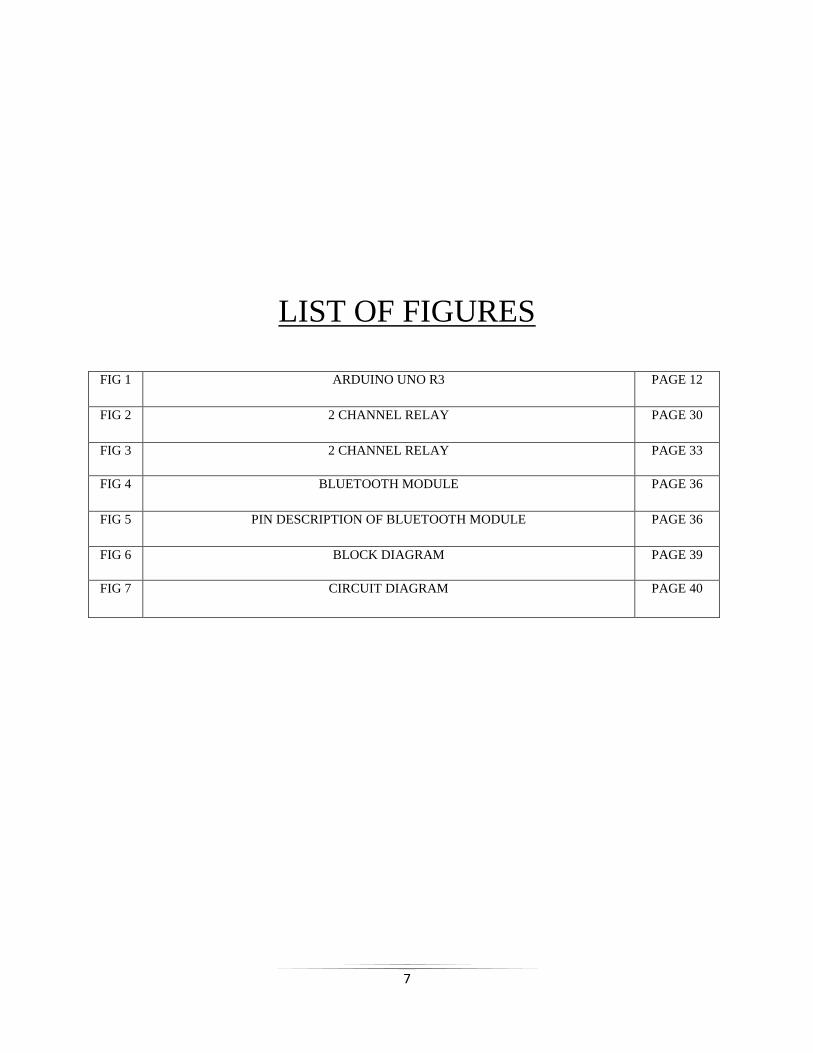
LIST OF FIGURES
FIG 1 ARDUINO UNO R3 PAGE 12
FIG 2 2 CHANNEL RELAY PAGE 30
FIG 3 2 CHANNEL RELAY PAGE 33
FIG 4 BLUETOOTH MODULE PAGE 36
FIG 5 PIN DESCRIPTION OF BLUETOOTH MODULE PAGE 36
FIG 6 BLOCK DIAGRAM PAGE 39
FIG 7 CIRCUIT DIAGRAM PAGE 40
8
INTRODUCTION
Nowadays, we have remote controls for our television sets and other electronic systems, which
have made our lives real easy. Have you ever wondered about home automation which would
give the facility of controlling tube lights, fans and other electrical appliances at home using a
remote control? Off-course, Yes! But, are the available options cost-effective? If the answer is
No, we have found a solution to it. We have come up with a new system called Arduino based
home automation using Bluetooth. This system is super-cost effective and can give the user, the
ability to control any electronic device without even spending for a remote control. This project
helps the user to control all the electronic devices using his/her smartphone. Time is a very
valuable thing. Everybody wants to save time as much as they can. New technologies are being
introduced to save our time. To save people’s time we are introducing Home Automation
system using Bluetooth . With the help of this system you can control your home appliances
from your mobile phone. You can turn on/off your home appliances within the range of
Bluetooth.

9
COMPONENTS REQUIRED
1)ARDUINO UNO
2)2 CHANNEL RELAY(5v)
3)BLUETOOTH MODULE HC05
4)POWER SUPPLY
5)LOAD(BULB 220V)
6)CONNECTING WIRES
7)VERO BOARD
8)SMARTPHONE(BLUETOOTH ENABLED)
10
DESCRIPTION
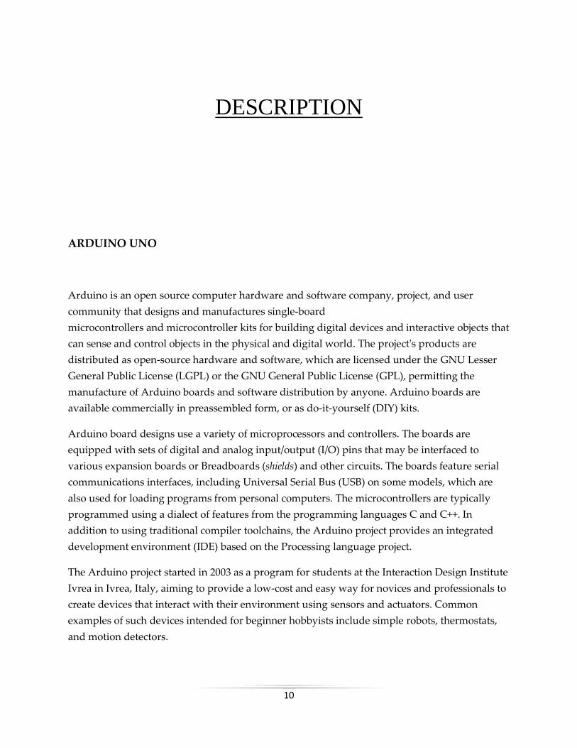
ARDUINO UNO
Arduino is an open source computer hardware and software company, project, and user
community that designs and manufactures single-board
microcontrollers and microcontroller kits for building digital devices and interactive objects that
can sense and control objects in the physical and digital world. The project's products are
distributed as open-source hardware and software, which are licensed under the GNU Lesser
General Public License (LGPL) or the GNU General Public License (GPL), permitting the
manufacture of Arduino boards and software distribution by anyone. Arduino boards are
available commercially in preassembled form, or as do-it-yourself (DIY) kits.
Arduino board designs use a variety of microprocessors and controllers. The boards are
equipped with sets of digital and analog input/output (I/O) pins that may be interfaced to
various expansion boards or Breadboards (shields) and other circuits. The boards feature serial
communications interfaces, including Universal Serial Bus (USB) on some models, which are
also used for loading programs from personal computers. The microcontrollers are typically
programmed using a dialect of features from the programming languages C and C++. In
addition to using traditional compiler toolchains, the Arduino project provides an integrated
development environment (IDE) based on the Processing language project.
The Arduino project started in 2003 as a program for students at the Interaction Design Institute
Ivrea in Ivrea, Italy, aiming to provide a low-cost and easy way for novices and professionals to
create devices that interact with their environment using sensors and actuators. Common
examples of such devices intended for beginner hobbyists include simple robots, thermostats,
and motion detectors.

11
The name Arduino comes from a bar in Ivrea, Italy, where some of the founders of the project
used to meet. The bar was named after Arduin of Ivrea, who was the margrave of the March of
Ivrea and King of Italy from 1002 to 1014.
Features of the Arduino UNO:
Microcontroller: ATmega328
Operating Voltage: 5V
Input Voltage (recommended): 7-12V
Input Voltage (limits): 6-20V
Digital I/O Pins: 14 (of which 6 provide PWM output)
Analog Input Pins: 6
DC Current per I/O Pin: 40 mA
DC Current for 3.3V Pin: 50 mA
Flash Memory: 32 KB of which 0.5 KB used by bootloader
SRAM: 2 KB (ATmega328)
EEPROM: 1 KB (ATmega328)
Clock Speed: 16 MHz

12
FIG 1 ARDUINO UNO R3

13
ARDUINO HARDWARE PART:-
Arduino is open-source hardware. The hardware reference designs are distributed under
a Creative Commons Attribution Share-Alike 2.5 license and are available on the Arduino
website. Layout and production files for some versions of the hardware are also available.
Although the hardware and software designs are freely available under copyleft licenses, the
developers have requested the name Arduinoto be exclusive to the official product and not be
used for derived works without permission. The official policy document on use of the Arduino
name emphasizes that the project is open to incorporating work by others into the official
product. Several Arduino-compatible products commercially released have avoided the project
name by using various names ending in -duino.
Most Arduino boards consist of an Atmel 8-bit
AVR microcontroller (ATmega8, ATmega168, ATmega328, ATmega1280, ATmega2560) with
varying amounts of flash memory, pins, and features. The 32-bit Arduino Due, based on the
Atmel SAM3X8E was introduced in 2012. The boards use single or double-row pins or female
headers that facilitate connections for programming and incorporation into other circuits. These
may connect with add-on modules termed shields. Multiple and possibly stacked shields may be
individually addressable via an I²C serial bus. Most boards include a 5 V linear regulator and a
16 MHz crystal oscillator or ceramic resonator. Some designs, such as the LilyPad, run at 8 MHz
and dispense with the onboard voltage regulator due to specific form-factor restrictions.
Arduino microcontrollers are pre-programmed with a boot loader that simplifies uploading of
programs to the on-chip flash memory. The default bootloader of the Arduino UNO is the
optiboot bootloader. Boards are loaded with program code via a serial connection to another
computer. Some serial Arduino boards contain a level shifter circuit to convert between RS-
232 logic levels and transistor–transistor logic(TTL) level signals. Current Arduino boards are
programmed via Universal Serial Bus (USB), implemented using USB-to-serial adapter chips
such as the FTDI FT232. Some boards, such as later-model Uno boards, substitute the FTDI chip
with a separate AVR chip containing USB-to-serial firmware, which is reprogrammable via its
own ICSP header. Other variants, such as the Arduino Mini and the unofficial Boarduino, use a
detachable USB-to-serial adapter board or cable, Bluetooth or other methods. When used with

14
traditional microcontroller tools, instead of the Arduino IDE, standard AVR in-system
programming (ISP) programming is used.
The Arduino board exposes most of the microcontroller's I/O pins for use by other circuits.
The Diecimila, Duemilanove, and current Uno provide 14 digital I/O pins, six of which can
produce pulse-width modulated signals, and six analog inputs, which can also be used as six
digital I/O pins. These pins are on the top of the board, via female 0.1-inch (2.54 mm) headers.
Several plug-in application shields are also commercially available. The Arduino Nano, and
Arduino-compatible Bare Bones Board and Boarduino boards may provide male header pins on
the underside of the board that can plug into solderless breadboards.
Many Arduino-compatible and Arduino-derived boards exist. Some are functionally equivalent
to an Arduino and can be used interchangeably. Many enhance the basic Arduino by adding
output drivers, often for use in school-level education, to simplify making buggies and small
robots. Others are electrically equivalent but change the form factor, sometimes retaining
compatibility with shields, sometimes not. Some variants use different processors, of varying
compatibility.

15
ARDUINO SOFTWARE PART:-
IDE
The Arduino integrated development environment (IDE) is a cross-platform application
(for Windows, macOS, Linux) that is written in the programming language Java. It originated
from the IDE for the languages Processing and Wiring. It includes a code editor with features
such as text cutting and pasting, searching and replacing text, automatic indenting, brace
matching, and syntax highlighting, and provides simple one-click mechanisms to compile and
upload programs to an Arduino board. It also contains a message area, a text console, a toolbar
with buttons for common functions and a hierarchy of operation menus. The source code for the
IDE is released under the GNU General Public License, version 2.
The Arduino IDE supports the languages C and C++ using special rules of code structuring. The
Arduino IDE supplies a software library from the Wiring project, which provides many
common input and output procedures. User-written code only requires two basic functions, for
starting the sketch and the main program loop, that are compiled and linked with a program
stub main() into an executable cyclic executive program with the GNU toolchain, also included
with the IDE distribution. The Arduino IDE employs the program avrdude to convert the
executable code into a text file in hexadecimal encoding that is loaded into the Arduino board
by a loader program in the board's firmware.
Sketch
A program written with the Arduino IDE is called a sketch.[58] Sketches are saved on the
development computer as text files with the file extension .ino. Arduino Software (IDE) pre-1.0
saved sketches with the extension .pde.

16
A minimal Arduino C/C++ program consist of only two functions:
setup(): This function is called once when a sketch starts after power-up or reset. It is used to
initialize variables, input and output pin modes, and other libraries needed in the sketch.
loop(): After setup() has been called, function loop() is executed repeatedly in the main program.
It controls the board until the board is powered off or is reset.
Blink example
Most Arduino boards contain a light-emitting diode (LED) and a load resistor connected
between pin 13 and ground, which is a convenient feature for many tests and program
functions. A typical program for a beginning Arduino programmer blinks a LED repeatedly.
This program uses the functions pinMode(), digitalWrite(), and delay(), which are provided by the
internal libraries included in the IDE environment. This program is usually loaded into a new
Arduino board by the manufacturer.
17
RELAY:
A relay is an electrically operated switch. Many relays use an electromagnet to mechanically
operate a switch, but other operating principles are also used, such as solid-state relays. Relays
are used where it is necessary to control a circuit by a separate low-power signal, or where
several circuits must be controlled by one signal. The first relays were used in long
distance telegraph circuits as amplifiers: they repeated the signal coming in from one circuit and
re-transmitted it on another circuit. Relays were used extensively in telephone exchanges and
early computers to perform logical operations.
A type of relay that can handle the high power required to directly control an electric motor or
other loads is called a contactor. Solid-state relayscontrol power circuits with no moving parts,
instead using a semiconductor device to perform switching. Relays with calibrated operating
characteristics and sometimes multiple operating coils are used to protect electrical circuits from
overload or faults; in modern electric power systems these functions are performed by digital
instruments still called "protective relays".
Magnetic latching relays require one pulse of coil power to move their contacts in one direction,
and another, redirected pulse to move them back. Repeated pulses from the same input have no
effect. Magnetic latching relays are useful in applications where interrupted power should not
be able to transition the contacts.
Magnetic latching relays can have either single or dual coils. On a single coil device, the relay
will operate in one direction when power is applied with one polarity, and will reset when the
polarity is reversed. On a dual coil device, when polarized voltage is applied to the reset coil the
contacts will transition. AC controlled magnetic latch relays have single coils that employ
steering diodes to differentiate between operate and reset commands.

18
A type of relay that can handle the high power required to directly control an electric motor or
other loads is called a contactor. Solid-state relayscontrol power circuits with no moving parts,
instead using a semiconductor device to perform switching. Relays with calibrated operating
characteristics and sometimes multiple operating coils are used to protect electrical circuits from
overload or faults; in modern electric power systems these functions are performed by digital
instruments still called "protective relays".
The Arduino Relay module allows a wide range of microcontroller such as Arduino, AVR ,PIC,
ARM with digital outputs to control larger loads and devices like AC or DC Motors,
electromagnets, solenoids, and incandescent light bulbs. This module is designed to be
integrated with 2 relays that it is capable of control 2 relays.The relay shield use one QIANJI
JQC-3F high-quality relay with rated load 7A/240VAC,10A/125VAC,10A/28VDC.The relay
output state is individually indicated by a light-emitting diode.
2 channel relay features:
Number of Relays: 2
Control signal: TTL level
Rated load: 7A/240VAC 10A/125VAC 10A/28VDC
Contact action time: 10ms/5ms

19
Types:-
1)Coaxial relay
Where radio transmitters and receivers share one antenna, often a coaxial relay is used as a TR
(transmit-receive) relay, which switches the antenna from the receiver to the transmitter. This
protects the receiver from the high power of the transmitter. Such relays are often used
in transceivers which combine transmitter and receiver in one unit. The relay contacts are
designed not to reflect any radio frequency power back toward the source, and to provide very
high isolation between receiver and transmitter terminals. The characteristic impedance of the
relay is matched to the transmission line impedance of the system, for example, 50 ohms.
2)Contactor
A contactor is a heavy-duty relay with higher current ratings, used for switching electric
motors and lighting loads. Continuous current ratings for common contactors range from 10
amps to several hundred amps. High-current contacts are made with alloys containing silver.
The unavoidable arcing causes the contacts to oxidize; however, silver oxide is still a good
conductor. Contactors with overload protection devices are often used to start motors.

20
3)Force-guided contacts relay
A 'force-guided contacts relay' has relay contacts that are mechanically linked together, so that
when the relay coil is energized or de-energized, all of the linked contacts move together. If one
set of contacts in the relay becomes immobilized, no other contact of the same relay will be able
to move. The function of force-guided contacts is to enable the safety circuit to check the status
of the relay. Force-guided contacts are also known as "positive-guided contacts", "captive
contacts", "locked contacts", "mechanically linked contacts", or "safety relays".
These safety relays have to follow design rules and manufacturing rules that are defined in one
main machinery standard EN 50205 : Relays with forcibly guided (mechanically linked)
contacts. These rules for the safety design are the one that are defined in type B standards such
as EN 13849-2 as Basic safety principles and Well-tried safety principles for machinery that
applies to all machines.
Force-guided contacts by themselves can not guarantee that all contacts are in the same state,
however they do guarantee, subject to no gross mechanical fault, that no contacts are in
opposite states. Otherwise, a relay with several normally open (NO) contacts may stick when
energised, with some contacts closed and others still slightly open, due to mechanical
tolerances. Similarly, a relay with several normally closed (NC) contacts may stick to the
unenergised position, so that when energised, the circuit through one set of contacts is broken,
with a marginal gap, while the other remains closed. By introducing both NO and NC contacts,
or more commonly, changeover contacts, on the same relay, it then becomes possible to
guarantee that if any NC contact is closed, all NO contacts are open, and conversely, if any NO
contact is closed, all NC contacts are open. It is not possible to reliably ensure that any
particular contact is closed, except by potentially intrusive and safety-degrading sensing of its
circuit conditions, however in safety systems it is usually the NO state that is most important,
and as explained above, this is reliably verifiable by detecting the closure of a contact of
opposite sense.
Force-guided contact relays are made with different main contact sets, either NO, NC or
changeover, and one or more auxiliary contact sets, often of reduced current or voltage rating,
used for the monitoring system. Contacts may be all NO, all NC, changeover, or a mixture of
these, for the monitoring contacts, so that the safety system designer can select the correct
21
configuration for the particular application. Safety relays are used as part of an engineered
safety system.
4)Latching relay
A latching relay (also called "impulse", "bistable", "keep", or "stay" relays) maintains either
contact position indefinitely without power applied to the coil. The advantage is that one coil
consumes power only for an instant while the relay is being switched, and the relay contacts
retain this setting across a power outage. A latching relay allows remote control of building
lighting without the hum that may be produced from a continuously (AC) energized coil.
In one mechanism, two opposing coils with an over-center spring or permanent magnet hold
the contacts in position after the coil is de-energized. A pulse to one coil turns the relay on and a
pulse to the opposite coil turns the relay off. This type is widely used where control is from
simple switches or single-ended outputs of a control system, and such relays are found
in avionics and numerous industrial applications.
Another latching type has a remanent core that retains the contacts in the operated position by
the remanent magnetism in the core. This type requires a current pulse of opposite polarity to
release the contacts. A variation uses a permanent magnet that produces part of the force
required to close the contact; the coil supplies sufficient force to move the contact open or closed
by aiding or opposing the field of the permanent magnet. A polarity controlled relay needs
changeover switches or an H bridge drive circuit to control it. The relay may be less expensive
than other types, but this is partly offset by the increased costs in the external circuit.
In another type, a ratchet relay has a ratchet mechanism that holds the contacts closed after the
coil is momentarily energized. A second impulse, in the same or a separate coil, releases the
contacts. This type may be found in certain cars, for headlamp dipping and other functions
where alternating operation on each switch actuation is needed.
A stepping relay is a specialized kind of multi-way latching relay designed for early
automatic telephone exchanges.

22
An earth leakage circuit breaker includes a specialized latching relay.
Very early computers often stored bits in a magnetically latching relay, such as ferreed or the
later remreed in the 1ESS switch.
Some early computers used ordinary relays as a kind of latch—they store bits in ordinary wire
spring relays or reed relays by feeding an output wire back as an input, resulting in a feedback
loop or sequential circuit. Such an electrically latching relay requires continuous power to
maintain state, unlike magnetically latching relays or mechanically racheting relays.
In computer memories, latching relays and other relays were replaced by delay line memory,
which in turn was replaced by a series of ever-faster and ever-smaller memory technologies.
5)Machine tool relay
A machine tool relay is a type standardized for industrial control of machine tools, transfer
machines, and other sequential control. They are characterized by a large number of contacts
(sometimes extendable in the field) which are easily converted from normally open to normally
closed status, easily replaceable coils, and a form factor that allows compactly installing many
relays in a control panel. Although such relays once were the backbone of automation in such
industries as automobile assembly, the programmable logic controller (PLC) mostly displaced
the machine tool relay from sequential control applications.
A relay allows circuits to be switched by electrical equipment: for example, a timer circuit with
a relay could switch power at a preset time. For many years relays were the standard method of
controlling industrial electronic systems. A number of relays could be used together to carry out
complex functions (relay logic). The principle of relay logic is based on relays which energize
and de-energize associated contacts. Relay logic is the predecessor of ladder logic, which is
commonly used in programmable logic controllers.

23
6)Mercury relay
A mercury relay is a relay that uses mercury as the switching element. They are used where
contact erosion would be a problem for conventional relay contacts. Owing to environmental
considerations about significant amount of mercury used and modern alternatives, they are
now comparatively uncommon.
7)Mercury-wetted relay
A mercury-wetted reed relay is a form of reed relay in which the contacts are wetted
with mercury. Such relays are used to switch low-voltage signals (one volt or less) where the
mercury reduces the contact resistance and associated voltage drop, for low-current signals
where surface contamination may make for a poor contact, or for high-speed applications
where the mercury eliminates contact bounce. Mercury wetted relays are position-sensitive and
must be mounted according to the manufacturer's specifications to work properly. Because of
the toxicity and expense of liquid mercury, these relays are now rarely used.
The mercury-wetted relay has one particular advantage, in that the contact closure appears to
be virtually instantaneous, as the mercury globules on each contact coalesce. The current rise
time through the contacts is generally considered to be a few picoseconds, however in a
practical circuit it will be limited by the inductance of the contacts and wiring. It was quite
common, before the restrictions on the use of mercury, to use a mercury-wetted relay in the
laboratory as a convenient means of generating fast rise time pulses, however although the rise
time may be picoseconds, the exact timing of the event is, like all other types of relay, subject to
considerable jitter, possibly milliseconds, due to mechanical imperfections.
The same coalescence process causes another effect, which is a nuisance in some applications.
The contact resistance is not stable immediately after contact closure, and drifts, mostly
downwards, for several seconds after closure, the change perhaps being 0.5 ohm.
8)Multi-voltage relays
24
Multi-voltage relays are devices designed to work for wide voltage ranges such as 24 to 240
VAC and VDC and wide frequency ranges such as 0 to 300 Hz. They are indicated for use in
installations that do not have stable supply voltages.
9)Overload protection relay
Electric motors need overcurrent protection to prevent damage from over-loading the motor, or
to protect against short circuits in connecting cables or internal faults in the motor
windings. The overload sensing devices are a form of heat operated relay where a coil heats
a bimetallic strip, or where a solder pot melts, releasing a spring to operate auxiliary
contacts. These auxiliary contacts are in series with the coil. If the overload senses excess current
in the load, the coil is de-energized.
This thermal protection operates relatively slowly allowing the motor to draw higher starting
currents before the protection relay will trip. Where the overload relay is exposed to the same
ambient temperature as the motor, a useful though crude compensation for motor ambient
temperature is provided.
The other common overload protection system uses an electromagnet coil in series with the
motor circuit that directly operates contacts. This is similar to a control relay but requires a
rather high fault current to operate the contacts. To prevent short over current spikes from
causing nuisance triggering the armature movement is damped with a dashpot. The thermal
and magnetic overload detections are typically used together in a motor protection relay.
Electronic overload protection relays measure motor current and can estimate motor winding
temperature using a "thermal model" of the motor armature system that can be set to provide
more accurate motor protection. Some motor protection relays include temperature detector
inputs for direct measurement from a thermocouple or resistance thermometersensor
embedded in the winding.

25
10)Polarized relay
A polarized relay places the armature between the poles of a permanent magnet to increase
sensitivity. Polarized relays were used in middle 20th Century telephone exchanges to detect
faint pulses and correct telegraphic distortion.
11)Reed relay
A reed relay is a reed switch enclosed in a solenoid. The switch has a set of contacts inside
an evacuated or inert gas-filled glass tube which protects the contacts against
atmospheric corrosion; the contacts are made of magnetic material that makes them move
under the influence of the field of the enclosing solenoid or an external magnet.
Reed relays can switch faster than larger relays and require very little power from the control
circuit. However, they have relatively low switching current and voltage ratings. Though rare,
the reeds can become magnetized over time, which makes them stick 'on' even when no current
is present; changing the orientation of the reeds with respect to the solenoid's magnetic field can
resolve this problem.
Sealed contacts with mercury-wetted contacts have longer operating lives and less contact
chatter than any other kind of relay.
12)Safety relays

26
Safety relays are devices which generally implement safety functions. In the event of a hazard,
the task of such a safety function is to use appropriate measures to reduce the existing risk to an
acceptable level.
13)Solid-state contactor
A solid-state contactor is a heavy-duty solid state relay, including the necessary heat sink, used
where frequent on-off cycles are required, such as with electric heaters, small electric motors,
and lighting loads. There are no moving parts to wear out and there is no contact bounce due to
vibration. They are activated by AC control signals or DC control signals from programmable
logic controllers (PLCs), PCs, transistor-transistor logic (TTL) sources, or other microprocessor
and microcontroller controls.
14)Solid-state relay
A solid-state relay (SSR) is a solid state electronic component that provides a function similar to
an electromechanical relay but does not have any moving components, increasing long-term
reliability. A solid-state relay uses a thyristor, TRIAC or other solid-state switching device,
activated by the control signal, to switch the controlled load, instead of a solenoid.
An optocoupler (a light-emitting diode (LED) coupled with a photo transistor) can be used to
isolate control and controlled circuits.
15)Static relay
A static relay consists of electronic circuitry to emulate all those characteristics which are
achieved by moving parts in an electro-magnetic relay.
16)Time delay relay

27
Timing relays are arranged for an intentional delay in operating their contacts. A very short (a
fraction of a second) delay would use a copper disk between the armature and moving blade
assembly. Current flowing in the disk maintains magnetic field for a short time, lengthening
release time. For a slightly longer (up to a minute) delay, a dashpot is used. A dashpot is a
piston filled with fluid that is allowed to escape slowly; both air-filled and oil-filled dashpots
are used. The time period can be varied by increasing or decreasing the flow rate. For longer
time periods, a mechanical clockwork timer is installed. Relays may be arranged for a fixed
timing period, or may be field adjustable, or remotely set from a control panel. Modern
microprocessor-based timing relays provide precision timing over a great range.
Some relays are constructed with a kind of "shock absorber" mechanism attached to the
armature which prevents immediate, full motion when the coil is either energized or de-
energized. This addition gives the relay the property of time-delay actuation. Time-delay relays
can be constructed to delay armature motion on coil energization, de-energization, or both.
Time-delay relay contacts must be specified not only as either normally open or normally
closed, but whether the delay operates in the direction of closing or in the direction of opening.
The following is a description of the four basic types of time-delay relay contacts.
First we have the normally open, timed-closed (NOTC) contact. This type of contact is normally
open when the coil is unpowered (de-energized). The contact is closed by the application of
power to the relay coil, but only after the coil has been continuously powered for the specified
amount of time. In other words, the direction of the contact's motion (either to close or to open)
is identical to a regular NO contact, but there is a delay in closing direction. Because the delay
occurs in the direction of coil energization, this type of contact is alternatively known as a
normally open, on-delay.
17)Vacuum relay
A sensitive relay having its contacts mounted in a highly evacuated glass housing, to permit
handling radio-frequency voltages as high as 20,000 volts without flashover between contacts
even though contact spacing is but a few hundredths of an inch when open.
Pole and throw[edit]
Since relays are switches, the terminology applied to switches is also applied to relays; a relay
switches one or more poles, each of whose contacts can be thrown by energizing the coil.

28
Normally open (NO) contacts connect the circuit when the relay is activated; the circuit is
disconnected when the relay is inactive. Normally closed (NC) contacts disconnect the circuit
when the relay is activated; the circuit is connected when the relay is inactive. All of the contact
forms involve combinations of NO and NC connections.
The National Association of Relay Manufacturers and its successor, the Relay and Switch
Industry Association define 23 distinct electrical contact forms found in relays and
switches.[23] Of these, the following are commonly encountered:
SPST-NO (Single-Pole Single-Throw, Normally-Open) relays have a single Form A contact
or make contact. These have two terminals which can be connected or disconnected. Including
two for the coil, such a relay has four terminals in total.
SPST-NC (Single-Pole Single-Throw, Normally-Closed) relays have a single Form
B or break contact. As with an SPST-NO relay, such a relay has four terminals in total.
SPDT (Single-Pole Double-Throw) relays have a single set of Form C, break before
make or transfer contacts. That is, a common terminal connects to either of two others, never
connecting to both at the same time. Including two for the coil, such a relay has a total of five
terminals.
DPST – Double-Pole Single-Throw relays are equivalent to a pair of SPST switches or relays
actuated by a single coil. Including two for the coil, such a relay has a total of six terminals. The
poles may be Form A or Form B (or one of each; the designations NO and NCshould be used to
resolve the ambiguity).
DPDT – Double-Pole Double-Throw relays have two sets of Form C contacts. These are
equivalent to two SPDT switches or relays actuated by a single coil. Such a relay has eight
terminals, including the coil
The S (single) or D (double) designator for the pole count may be replaced with a number,
indicating multiple contacts connected to a single actuator. For example, 4PDT indicates a four-
pole double-throw relay that has 12 switching terminals.
EN 50005 are among applicable standards for relay terminal numbering; a typical EN 50005-
compliant SPDT relay's terminals would be numbered 11, 12, 14, A1 and A2 for the C, NC, NO,
and coil connections, respectively.[24]
DIN 72552 defines contact numbers in relays for automotive use;
85 = relay coil -

29
86 = relay coil +
87 = common contact
87a = normally closed contact
87b = normally open contact
APPLICATIONS OF RELAY:-
Relays are used wherever it is necessary to control a high power or high voltage circuit with a
low power circuit, especially when galvanic isolation is desirable. The first application of relays
was in long telegraph lines, where the weak signal received at an intermediate station could
control a contact, regenerating the signal for further transmission. High-voltage or high-current
devices can be controlled with small, low voltage wiring and pilots switches. Operators can be
isolated from the high voltage circuit. Low power devices such as microprocessors can drive
relays to control electrical loads beyond their direct drive capability. In an automobile, a starter
relay allows the high current of the cranking motor to be controlled with small wiring and
contacts in the ignition key.
Electromechanical switching systems including Strowger and Crossbar telephone exchanges
made extensive use of relays in ancillary control circuits. The Relay Automatic Telephone
Company also manufactured telephone exchanges based solely on relay switching techniques
designed by Gotthilf Ansgarius Betulander. The first public relay based telephone exchange in
the UK was installed in Fleetwood on 15 July 1922 and remained in service until 1959.
The use of relays for the logical control of complex switching systems like telephone exchanges
was studied by Claude Shannon, who formalized the application of Boolean algebra to relay
circuit design in A Symbolic Analysis of Relay and Switching Circuits. Relays can perform the
basic operations of Boolean combinatorial logic. For example, the boolean AND function is
realised by connecting normally open relay contacts in series, the OR function by connecting

30
normally open contacts in parallel. Inversion of a logical input can be done with a normally
closed contact. Relays were used for control of automated systems for machine tools and
production lines. The Ladder programming language is often used for designing relay
logic networks.
Early electro-mechanical computers such as the ARRA, Harvard Mark II, Zuse Z2, and Zuse
Z3 used relays for logic and working registers. However, electronic devices proved faster and
easier to use.
Because relays are much more resistant than semiconductors to nuclear radiation, they are
widely used in safety-critical logic, such as the control panels of radioactive waste-handling
machinery. Electromechanical protective relays are used to detect overload and other faults on
electrical lines by opening and closing circuit breakers.

31
RELAY H152S MODULE
Overview
We can control high voltage electronic devices using relays. A Relay is actually a switch which
is electrically operated by an electromagnet. The electromagnet is activated with a low voltage,
for example 5 volts from a microcontroller and it pulls a contact to make or break a high voltage
circuit.
FIG 2: 2 CHANNEL RELAY
As an example for this Arduino Relay Tutorial we will use the HL-52S 2 channel relay module,
which has 2 relays with rating of 10A @ 250 and 125 V AC and 10A @ 30 and 28 V DC. The high
voltage output connector has 3 pins, the middle one is the common pin and as we can see from
the markings one of the two other pins is for normally open connection and the other one for
normally closed connection.
On the other side of the module we have these 2 sets of pins. The first one has 4 pins, a Ground
and a VCC pin for powering the module and 2 input pins In1 and In2. The second set of pins
has 3 pins with a jumper between the JDVcc and the Vcc pin. With a configuration like this the
electromagnet of the relay is directly powered from the Arduino Board and if something goes
wrong with the relay the microcontroller could get damaged.

32
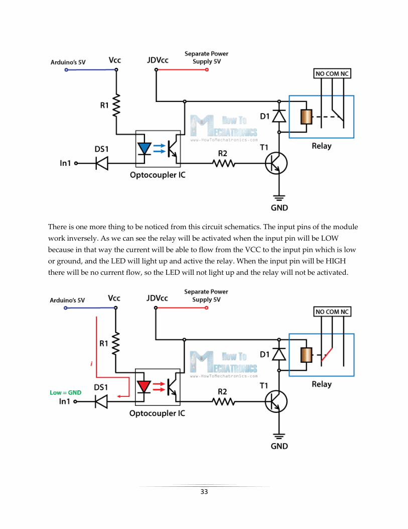
Circuit Schematic
For better understanding let’s see the circuit schematics of the relay module in this
configuration. So we can see that the 5 volts from our microcontroller connected to the Vcc pin
for activating the relay through the Optocoupler IC are also connected to the JDVcc pin which
powers the electromagnet of the relay. So in this case we got no isolation between the relay and
the microcontroller.
In order to isolate the microcontroller from the relay, we need to remove the jumper and
connect separate power supply for the electromagnet to the JDVcc and the Ground pin. Now
with this configuration the microcontroller doesn’t have any physical connection with the relay,
it just uses the LED light of the Optocoupler IC to activate the relay.
33
There is one more thing to be noticed from this circuit schematics. The input pins of the module
work inversely. As we can see the relay will be activated when the input pin will be LOW
because in that way the current will be able to flow from the VCC to the input pin which is low
or ground, and the LED will light up and active the relay. When the input pin will be HIGH
there will be no current flow, so the LED will not light up and the relay will not be activated.
34
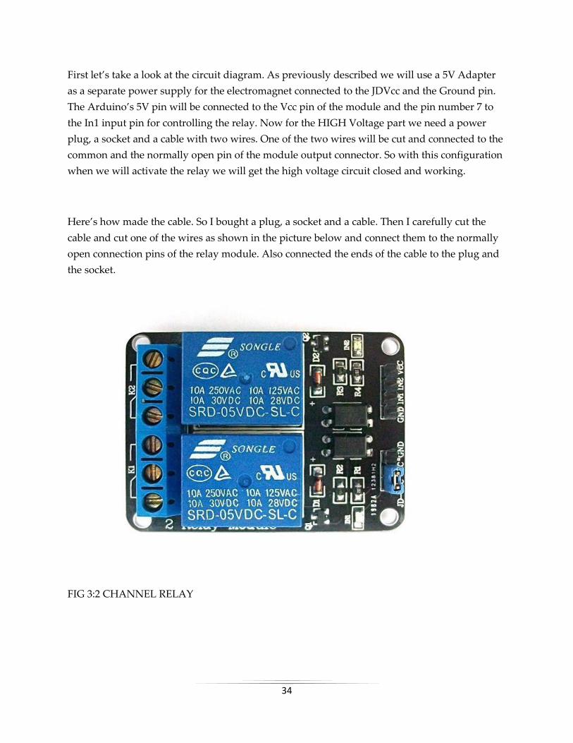
First let’s take a look at the circuit diagram. As previously described we will use a 5V Adapter
as a separate power supply for the electromagnet connected to the JDVcc and the Ground pin.
The Arduino’s 5V pin will be connected to the Vcc pin of the module and the pin number 7 to
the In1 input pin for controlling the relay. Now for the HIGH Voltage part we need a power
plug, a socket and a cable with two wires. One of the two wires will be cut and connected to the
common and the normally open pin of the module output connector. So with this configuration
when we will activate the relay we will get the high voltage circuit closed and working.
Here’s how made the cable. So I bought a plug, a socket and a cable. Then I carefully cut the
cable and cut one of the wires as shown in the picture below and connect them to the normally
open connection pins of the relay module. Also connected the ends of the cable to the plug and
the socket.
FIG 3:2 CHANNEL RELAY

35
BLUETOOTH MODULE(HC-05 Bluetooth Module)
HC-05 Specification:
Bluetooth protocal: Bluetooth Specification v2.0+EDR
Frequency: 2.4GHz ISM band
Modulation: GFSK(Gaussian Frequency Shift Keying)
Emission power: ≤4dBm, Class 2
Sensitivity: ≤-84dBm at 0.1% BER
Speed: Asynchronous: 2.1Mbps(Max) / 160 kbps, Synchronous: 1Mbps/1Mbps
Security: Authentication and encryption
Profiles: Bluetooth serial port
Power supply: +3.3VDC 50mA
Working temperature: -20 ~ +75Centigrade
Dimension: 26.9mm x 13mm x 2.2 mm
36
Overview
HC‐05 module is an easy to use Bluetooth SPP (Serial Port Protocol) module,designed for
transparent wireless serial connection setup.The HC-05 Bluetooth Module can be used in a
Master or Slave configuration, making it a great solution for wireless communication.This serial
port bluetooth module is fully qualified Bluetooth V2.0+EDR (Enhanced Data Rate)3Mbps
Modulation with complete 2.4GHz radio transceiver and baseband. It uses CSR Bluecore 04‐
External single chip Rluetooth system with CMOS technology and with AFH (Adaptive
Frequency Hopping Feature).
Bluetooth Module HC-05
The Bluetooth module HC-05 is a MASTER/SLAVE module.By default the factory setting is
SLAVE.The Role of the module (Master or Slave) can be configured only by AT
COMMANDS.The slave modules cannot initiate a connection to another Bluetooth device, but
can accept connections.Master module can initiate a connection to other devices.The user can
use it simply for a serial port replacement to establish connection between MCU and GPS, PC to
your embedded project, etc.

37
FIG 4:BLUETOOTH MODULE
FIG 5 :PIN DESCRIPTION OF BLUETOOTH MODULE

38
Pin Description:-
The HC-05 Bluetooth Module has 6pins. They are as follows:
ENABLE:
When enable is pulled LOW, the module is disabled which means the module will not turn
on and it fails to communicate.When enable is left open or connected to 3.3V, the module is
enabled i.e the module remains onand communication also takes place.
Vcc:
Supply Voltage 3.3V to 5V
GND:
Ground pin
TXD & RXD:
These two pins acts as an UART interface for communication
STATE:
It acts as a status indicator.When the module is not connected to paired with any other
bluetooth device,signal goes Low.At this low state,the led flashes continuously which denotes
that the module is not paired with other device.When this module is connected to/paired with
any other bluetooth device,the signal goes High.At this high state,the led blinks with a constant
delay say for example 2s delay which indicates that the module is paired.
BUTTON SWITCH:
This is used to switch the module into AT command mode.To enable AT command mode,press
the button switch for a second.With the help of AT commands,the user can change the
parameters of this module but only when the module is not paired with any other BT device.If

39
the module is connected to any other bluetooth device, it starts to communicate with that device
and fails to work in AT command mode.
HC-05 Default Settings:-
Default Bluetooth Name: ‚HC-05‛
Default Password: 1234 or 0000
Default Communication: Slave
Default Mode: Data Mode
Data Mode Baud Rate: 9600, 8, N, 1
Command Mode Baud Rate: 38400, 8, N, 1
Default firmware: LINVOR

40
BLOCK DIAGRAM
FIG 6:BLOCK DIAGRAM OF HOME AUTOMATION SYSTEM USING ARDUINO AND
BLUETOOTH MODULE
Bluetooth Module
ARDUINO UNO R3
RELAY
MODULE
MAIN POWER
SOURCE(220V) 9 VOLT POWER
SOURCE
LOAD

41
CIRCUIT DIAGRAM
FIG 7:CIRCUIT DIAGRAM OF HOME AUTOMATION SYSTEM USING ARDUINO AND
BLUETOOTH MODULE

42
CODE
CODE :-
String inputs;
#define relay1 2 //Connect relay1 to pin 9
#define relay2 3 //Connect relay2 to pin 8
#define relay3 4 //Connect relay3 to pin 7
#define relay4 5 //Connect relay4 to pin 6
#define relay5 6 //Connect relay5 to pin 5
#define relay6 7 //Connect relay6 to pin 4
#define relay7 8 //Connect relay7 to pin 3
#define relay8 9 //Connect relay8 to pin 2
void setup()
{
Serial.begin(9600); //Set rate for communicating with phone
pinMode(relay1, OUTPUT); //Set relay1 as an output
pinMode(relay2, OUTPUT); //Set relay2 as an output
pinMode(relay3, OUTPUT); //Set relay1 as an output
pinMode(relay4, OUTPUT); //Set relay2 as an output
pinMode(relay5, OUTPUT); //Set relay1 as an output
pinMode(relay6, OUTPUT); //Set relay2 as an output
pinMode(relay7, OUTPUT); //Set relay1 as an output
pinMode(relay8, OUTPUT); //Set relay2 as an output
digitalWrite(relay1, LOW); //Switch relay1 off
digitalWrite(relay2, LOW); //Swtich relay2 off
digitalWrite(relay3, LOW); //Switch relay1 off
digitalWrite(relay4, LOW); //Swtich relay2 off
digitalWrite(relay5, LOW); //Switch relay1 off
digitalWrite(relay6, LOW); //Swtich relay2 off
digitalWrite(relay7, LOW); //Switch relay1 off
digitalWrite(relay8, LOW); //Swtich relay2 off
}
void loop()
{
while(Serial.available()) //Check if there are available bytes to read
{

43
delay(10); //Delay to make it stable
char c = Serial.read(); //Conduct a serial read
if (c == ‘#’){
break; //Stop the loop once # is detected after a word
}
inputs += c; //Means inputs = inputs + c
}
if (inputs.length() >0)
{
Serial.println(inputs);
if(inputs == ‚A‛)
{
digitalWrite(relay1, LOW);
}
else if(inputs == ‚a‛)
{
digitalWrite(relay1, HIGH);
}
else if(inputs == ‚B‛)
{
digitalWrite(relay2, LOW);
}
else if(inputs == ‚b‛)
{
digitalWrite(relay2, HIGH);
}
else if(inputs == ‚C‛)
{
digitalWrite(relay3, LOW);
}
else if(inputs == ‚c‛)
{
digitalWrite(relay3, HIGH);
}
else if(inputs == ‚D‛)
{
digitalWrite(relay4, LOW);
}
else if(inputs == ‚d‛)
{
digitalWrite(relay4, HIGH);
}

44
else if(inputs == ‚E‛)
{
digitalWrite(relay5, LOW);
}
else if(inputs == ‚e‛)
{
digitalWrite(relay5, HIGH);
}
else if(inputs == ‚F‛)
{
digitalWrite(relay6, LOW);
}
else if(inputs == ‚f‛)
{
digitalWrite(relay6, HIGH);
}
else if(inputs == ‚G‛)
{
digitalWrite(relay7, LOW);
}
else if(inputs == ‚g‛)
{
digitalWrite(relay7, HIGH);
}
else if(inputs == ‚H‛)
{
digitalWrite(relay8, LOW);
}
else if(inputs == ‚h‛)
{
digitalWrite(relay8, HIGH);
}
inputs=‛‛;
}
}
45
APPLICATIONS
Home Is Where the Smart Is
Evmachine-to-machine communication, and you understand you’re not the most tech-savvy
consumer, it’s impossible that you’ve missed the abundance of home automation products
filling the shelves and ads of every home improvement store. Suddenly an ordinary errand for
light bulbs will leave you wondering if your lamp could send you a message alerting you that
the light bulb needs to be replaced. Furthermore, if your lamp is talking to you, could your
refrigerator and sprinkler system be too? Experts say: Yes, the possibilities are endless. If that’s
the case, where do you begin?
Any day-to-day, repeatable process is automatable with smart home applications. The greater
the control and flexibility of these processes, the more energy and cost savings the resident
experiences, which are factors anyone who pays utilities strives to moderate. The smart home
revolution is likely to be more of an evolution, with the incorporation of one or two home
systems at a time, gradually automating our households through smart mobile devices.
However, with these elements of efficiency comes the question of ease of use. Will it bring you
enjoyment or exasperation? With so many brands and models already available in an ever-
growing market, how do you know which is best for you?
Lighting Control: Leaving the Dark Ages and Stepping Into the Light
Smart lighting allows you to control wall switches, blinds, and lamps, but how intuitive is a
lighting control system? It turns out, quite; its capabilities are extensive. You’re able to schedule
the times lights should turn on and off, decide which specific rooms should be illuminated at
certain times, select the level of light which should be emitted, and choose how particular lights
react through motion sensitivity, as seen with Belkin’s WeMo Switch + Motion, which is both
affordable and easy to use with its plug-and-play simplicity.
HVAC Regulation: No Longer Burned by Your Heating Bill
As fuel costs rise and the availability and sustainability of our resources becomes a greater
concern, heating/cooling our homes efficiently is less a budgetary bonus and more of a
necessity. Over the past year, smart thermostats and automated home heating systems have
become more readily available and easily incorporate into any home. Heating and cooling our

46
homes consumes an average of 50% of energy costs yearly, making daily HVAC regulation
progressively rewarding. Maintaining a substantial lead among the nearly non-existent
competition, the Nest Learning Thermostat, learns your heating and cooling preferences over
time, eliminating the need for programming and is accessible from your smartphone app. With
automated HVAC you are able to reduce the heat when a room is unoccupied, and increase or
decrease it at specific times based on your schedule and occupancy.
Lawn Irrigation Systems: The Grass is Always Greener
A lush and healthy lawn is a source of pride for most homeowners, but the weather doesn’t
always cooperate and provide the adequate elements for a flourishing landscape. For decades
we’ve relied on sprinkler systems to keep our yards at peak presentation, but at what cost? The
average American home spends approximately 30% of their daily water usage on lawn and
garden maintenance. Nearly half of that amount is wasted due to inefficiency. If you apply that
statistic to the national average, up to 4.5 billion gallons of water is wasted per day through
ineffective watering methods. If we reflect upon the monetary impact of this, it results in
Americans spending over a thousand dollars a year in water, with a portion of that being waste.
The global effects are even greater when you consider the growing concern over climate change
and the dramatic decrease in agricultural natural resources. However, sprinkler control
systems, like Skydrop, are providing water regulation through real-time communication with
local weather data. If a rainstorm develops and deposits two inches of rainwater on your lawn,
the automated sprinkler detects the saturation and disables its scheduled watering. Conversely,
the system will be alerted to dry conditions and supply the necessary amount of nourishment,
without over-watering.
Smart Appliances: What’s for Dinner?
Will smart kitchen appliances actually make you a better cook? Maybe. Smart refrigerators,
such as LG’s Smart ThinQ, allow you to scan grocery store receipts and keep an inventory of
your items, and alerts you if an item is about to expire. More impressively, it suggests recipes
based on your refrigerator’s contents and lets you know when you need to replace items. Smart
ovens synch with your smartphone and automatically preheat to the correct temperature based
on a recipe selected from your database. While these appliance options seem a bit superficial
and convenience based, there is a conservation factor as well. By automating your kitchen
appliance and making them accessible from your smart device, you’re able to sever the
electricity supplied to unused appliances and reduce your energy consumption and costs.
Considering the number of appliances the average household owns; this could save a
substantial amount of money over time.
47
Security Systems: Knock, Knock…
Who’s there? The Internet of Things. While efficiency and conservation are certainly IoT
benefits, its potential to have improved control over home security is a primary focus. Smart
locks, like Kwikset’s Kevo, a Bluetooth enabled electronic deadbolt, and various connected
home security systems, such as iSmartAlarm, offer a variety of features including door and
window sensors, motion detectors, video cameras and recording mechanisms. All of which are
connected to a mobile device and accessible via the cloud, thus enabling you to access real-time
information on the security status of your home. Naturally, there is a great deal of scrutiny
regarding the level of trust in controlling your home’s security system via a mobile device, but
it begs earnest exploration when weighing the potential benefits and peace of mind it provides
homeowners.
48
CONCLUSION
The system as the name indicates, ‘Home automation’ makes the system more flexible and
provides attractive user interface compared to other home automation systems. In this system
we integrate mobile devices into home automation systems. A novel architecture for a home
automation system is proposed using the relatively new communication technologies. The
system consists of mainly three components is a BLUETOOTH module, Arduino
microcontroller and relay circuits. WIFI is used as the communication channel between android
phone and the Arduino microcontroller. We hide the complexity of the notions involved in the
home automation system by including them into a simple, but comprehensive set of related
concepts. This simplification is needed to fit as much of the functionality on the limited space
offered by a mobile device’s display. This paper proposes a low cost, secure, ubiquitously
accessible, auto-configurable, remotely controlled solution. The approach discussed in the paper
is novel and has achieved the target to control home appliances remotely using the WiFi
technology to connects system parts, satisfying user needs and requirements. WiFi technology
capable solution has proved to be controlled remotely, provide home security and is cost-
effective as compared to the previously existing systems. Hence we can conclude that the
required goals and objectives of home automation system have been achieved. The system
design and architecture were discussed, and prototype presents the basic level of home
appliance control and remote monitoring has been implemented. Finally, the proposed system
is better from the scalability and flexibility point of view than the commercially available home
automation systems.
49
REFERENCE
1.Wikipedia
2. Wireless Sensor Networks: Concepts, Applications, Experimentation and Analysis. 2016.
p. 108. ISBN 9811004129. The use of standardized, with open standards over proprietary
protocols provides the industry with the freedom to choose between suppliers with guaranteed
interoperability. Standardized solutions usually have a much longer lifespan than proprietary
solutions.
3.Jump up^ "Research and Markets: Global Home Automation and Control Market 2014-2020 -
Lighting Control, Security & Access Control, HVAC Control Analysis of the $5.77 Billion
Industry". Reuters. 2015-01-19. Archived from the original on 2016-05-05.
4. Home Automation & Wiring (1 ed.). New York: McGraw-Hill/TAB Electronics. 1999-03-
31. ISBN 9780070246744.