
Holistic 3D Reconstruction of Urban Structures from …yang/paper/iccv11_3d...Holistic 3D...
8
Holistic 3D Reconstruction of Urban Structures from Low-Rank Textures Hossein Mobahi 1 , Zihan Zhou 2 , Allen Y. Yang 3 and Yi Ma 2,4 1 CS Dept., University of Illinois at Urbana-Champaign 2 ECE Dept., University of Illinois at Urbana-Champaign 3 EECS Dept., University of California, Berkeley 4 Visual Computing Group, Microsoft Research Asia {hmobahi2,zzhou7}@illinois.edu, [email protected], [email protected] Abstract We introduce a new approach to reconstructing accu- rate camera geometry and 3D models for urban structures in a holistic fashion, i.e., without relying on extraction or matching of traditional local features such as points and edges. Instead, we use semi-global or global features based on transform invariant low-rank textures, which are ubiqui- tous in urban scenes. Modern high-dimensional optimiza- tion techniques enable us to accurately and robustly recover precise and consistent camera calibration and scene geom- etry from single or multiple images of the scene. We demon- strate how to construct 3D models of large-scale buildings from sequences of multiple large-baseline uncalibrated im- ages that conventional SFM systems do not apply. 1. Introduction Recently, there has been tremendous interest in building large-scale 3D models for urban areas, which are largely driven by industrial applications such as Google Earth, Street View, and Microsoft’s Bing Maps. To meet the de- mands of such applications, significant progress about the structure-from-motion (SFM) techniques has been made in terms of the scalability and reliability [1, 21, 16, 6]. The conventional SFM approach to build a 3D model of a scene typically relies on detecting, matching, and triangu- lating a set of feature points (and edges) in multiple camera views, which has been extensively studied in the past two to three decades. One great advantage of working with point features is that the system can be somewhat oblivious to the scene: the scene could be of any shape or texture as long as the shape is rigid and texture is rich of distinguishable feature points. 1 In practice, researchers have observed that urban scenes often have very special types of shapes and textures, which may not be ideal for generic SFM techniques. On one hand, 1 Of course, there have been multiple parallel lines of work in studying 3D shape reconstruction for scenes that lack rich textures, using cues such as shape from shading and contours, etc. the shape of man-made objects (e.g., buildings, houses, and cars) normally has very regular global structures, rich of all types of symmetry and self-similarity. If a reconstruction algorithm can take advantage of such global information, it is natural to expect the algorithm to obtain more accu- rate estimates for both the 3D shape and camera locations from man-made objects than from generic 3D scenes. On the other hand, due to the same reason that urban scenes are full of symmetry, repetitive features pose significant chal- lenges for matching them across different views. The latter problem gets more drastic when the views are sparse and the baseline between views is large as in Figure 1. In order to handle wide-baseline images for SFM, which represent a large portion of images captured in popular ap- plications [21, 6], more sophisticated techniques have been proposed to extract and match richer image features beyond points and edges. Examples include affine-invariant fea- tures (SIFT) [12, 14, 15, 2], superpixels [16], and object part-based regions [26, 7], to name just a few. In addition to improving local-feature detection, it has long been noticed that 3D reconstruction of urban structures can be more ac- curate and simple if one can detect in advance certain salient symmetric patterns (see [11] for a review on this topic) or global structures such as vanishing points [17]. However, symmetry and vanishing points are global or semi-global properties of the scene structures. They cannot be easily extracted from any individual image features. Instead, they must be inferred from the relations among a group of related feature points or edges. Despite numerous attempts [18, 11], it remains a chal- lenging problem to reliably detect and extract large, sym- metric patterns. The reason is twofold: First, it is difficult to properly detect all the features that represent a symmet- ric pattern (say the four corners and four edges of a win- dow). Second, the task becomes more daunting in the pres- ence of outliers and partial occlusion in the extracted feature set, which obscure the dominant global structures. This is the main reason robust statistical techniques such as Hough transform or RANSAC have been widely used for such pur- 1
Transcript of Holistic 3D Reconstruction of Urban Structures from …yang/paper/iccv11_3d...Holistic 3D...

Holistic 3D Reconstruction of Urban Structures from Low-Rank Textures
Hossein Mobahi1, Zihan Zhou2, Allen Y. Yang3 and Yi Ma2,41CS Dept., University of Illinois at Urbana-Champaign2ECE Dept., University of Illinois at Urbana-Champaign
3EECS Dept., University of California, Berkeley4Visual Computing Group, Microsoft Research Asia
{hmobahi2,zzhou7}@illinois.edu, [email protected], [email protected]
AbstractWe introduce a new approach to reconstructing accu-
rate camera geometry and 3D models for urban structuresin a holistic fashion, i.e., without relying on extraction ormatching of traditional local features such as points andedges. Instead, we use semi-global or global features basedon transform invariant low-rank textures, which are ubiqui-tous in urban scenes. Modern high-dimensional optimiza-tion techniques enable us to accurately and robustly recoverprecise and consistent camera calibration and scene geom-etry from single or multiple images of the scene. We demon-strate how to construct 3D models of large-scale buildingsfrom sequences of multiple large-baseline uncalibrated im-ages that conventional SFM systems do not apply.
1. IntroductionRecently, there has been tremendous interest in building
large-scale 3D models for urban areas, which are largelydriven by industrial applications such as Google Earth,Street View, and Microsoft’s Bing Maps. To meet the de-mands of such applications, significant progress about thestructure-from-motion (SFM) techniques has been made interms of the scalability and reliability [1, 21, 16, 6].
The conventional SFM approach to build a 3D model ofa scene typically relies on detecting, matching, and triangu-lating a set of feature points (and edges) in multiple cameraviews, which has been extensively studied in the past two tothree decades. One great advantage of working with pointfeatures is that the system can be somewhat oblivious to thescene: the scene could be of any shape or texture as longas the shape is rigid and texture is rich of distinguishablefeature points.1
In practice, researchers have observed that urban scenesoften have very special types of shapes and textures, whichmay not be ideal for generic SFM techniques. On one hand,
1Of course, there have been multiple parallel lines of work in studying3D shape reconstruction for scenes that lack rich textures, using cues suchas shape from shading and contours, etc.
the shape of man-made objects (e.g., buildings, houses, andcars) normally has very regular global structures, rich of alltypes of symmetry and self-similarity. If a reconstructionalgorithm can take advantage of such global information,it is natural to expect the algorithm to obtain more accu-rate estimates for both the 3D shape and camera locationsfrom man-made objects than from generic 3D scenes. Onthe other hand, due to the same reason that urban scenes arefull of symmetry, repetitive features pose significant chal-lenges for matching them across different views. The latterproblem gets more drastic when the views are sparse andthe baseline between views is large as in Figure 1.
In order to handle wide-baseline images for SFM, whichrepresent a large portion of images captured in popular ap-plications [21, 6], more sophisticated techniques have beenproposed to extract and match richer image features beyondpoints and edges. Examples include affine-invariant fea-tures (SIFT) [12, 14, 15, 2], superpixels [16], and objectpart-based regions [26, 7], to name just a few. In addition toimproving local-feature detection, it has long been noticedthat 3D reconstruction of urban structures can be more ac-curate and simple if one can detect in advance certain salientsymmetric patterns (see [11] for a review on this topic) orglobal structures such as vanishing points [17]. However,symmetry and vanishing points are global or semi-globalproperties of the scene structures. They cannot be easilyextracted from any individual image features. Instead, theymust be inferred from the relations among a group of relatedfeature points or edges.
Despite numerous attempts [18, 11], it remains a chal-lenging problem to reliably detect and extract large, sym-metric patterns. The reason is twofold: First, it is difficultto properly detect all the features that represent a symmet-ric pattern (say the four corners and four edges of a win-dow). Second, the task becomes more daunting in the pres-ence of outliers and partial occlusion in the extracted featureset, which obscure the dominant global structures. This isthe main reason robust statistical techniques such as Houghtransform or RANSAC have been widely used for such pur-
1

Figure 1. Left Pair: Example of matched facades of a building. Right Pair: Automatically reconstructed 3D model from only fouruncalibrated images around the building by our method. Each image covers a pair of facades. The pyramids show the estimated locationof cameras.
poses. Finally, even when local features are reliably ex-tracted, it is not trivial to verify which ones satisfy whatsymmetric and/or vanishing point relations under cameraperspective projection [9]. To address these problems, therehas been increasing amount of work trying to infer approx-imate 3D geometry of image patches of urban scenes usingsupervised machine learning methods [10, 8, 20]. In con-trast, in this paper, we investigate a novel approach to inferaccurate 3D geometry from either single or multiple imagesof an urban scene in a mainly unsupervised fashion.
To avoid the aforementioned difficulties while inferring3D geometry, we exploit a new class of “building blocks”for modeling urban objects. These new tools complementlocal features such as points, edges, SIFT features, andgeneric local patches. The new building blocks shall havethe following good properties:
1. Holistic: They need to encode accurate, global geo-metric information such as structural symmetry, van-ishing points, and camera positions;
2. Invariant: Their representation should be invariant tocamera viewpoint and perspective distortion, so thatthey can be matched reliably across multiple images;
3. Robust: The extraction of such new features should benumerically stable and robust (say, to partial occlusionor random image noise and error).
Contributions. Motivated by a new type of image fea-ture called transform invariant low-rank texture (TILT) [25],in this paper, we study how such low-rank textures can beused as new building blocks for modeling urban scenes.The proposed new approach suggests that we can obtain ac-curate 3D models for urban objects such as buildings andhouses, without relying on extraction of any traditional lo-cal features such as points and edges. The new approach re-lies directly and exclusively on semi-global or global imagepatches and regions built from TILT features. For this veryreason, the approach is called “holistic.” We show how toobtain accurate information about camera calibration, ori-entation and position from each image, correspondence be-tween two images, and ultimately a consistent 3D structurefrom multiple images, as the example shown in Figure 1.
Admittedly, the proposed basic scheme cannot yet han-dle all comprehensive urban scenes, especially where low-rank texture is not abundant. Therefore, it should not be
Figure 2. Geometry from a low-rank patch on a building facade.Left: The red box represents the selected candidate region I , andthe green box corresponds to the recovered low-rank texture usingTILT. Right: The rectified building facade I0 = I ◦ τ using thehomography τ estimated from the low-rank texture.
treated as a replacement or competitor to the existing SFMsystems. Rather, the new tools introduced in this paperare more tailored to regular urban objects, and they shouldbe considered complementary to existing general-purposepoint-feature based SFM methods.
2. Geometry from One Facade of a BuildingFor completeness, we first give a brief review of work on
low-rank textures [25] and then show how to use them for3D modeling. It has been observed by the authors of [25]that the image of repetitive or symmetric patterns, whenviewed as a matrix, is low-rank. For example, if I0 is arectified frontal view of a planar patch on the facade of atypical office building (see Figure 2 right), then as a matrix,I0 has a rank much lower than its dimension. The authorscall such an image patch as a low-rank texture. In someother (perspective) view of the building (see Figure 2 left)the corresponding patch I deforms by a homography trans-form: I = I0 ◦ τ−1, where τ belongs to the homographygroup GL(3) and deforms the image domain.
One intriguing observation of the work [25] is that aslong as the patch is large enough and contains sufficienttexture, both the deformation τ and the view-invariant low-rank texture I0 can be accurately recovered from the ob-served I , up to scaling in each of the image coordinates.The basic idea is to solve for a transformation τ of I so thatI0 = I ◦ τ has the lowest possible rank. Furthermore, theimage patch I is often corrupted by noise and occlusion. Asa result, a more realistic model between the low-rank tex-ture I0 and its image I has been proposed by [25] as:
I ◦ τ = I0 + E, (1)
where E represents some sparse error that corrupts the im-age, say due to partial occlusion. As shown in the work [25]
and Robust PCA literature [4], the transformation τ and thelow-rank texture I0 can be recovered by solving the follow-ing optimization problem:
minA,E,τ
‖A‖∗ + λ‖E‖1 subject to I ◦ τ = A+ E, (2)
where ‖ · ‖∗ and ‖ · ‖1 represent the nuclear norm and `1-norm of a matrix, respectively 2.
The recovered low-rank texture A only differs from theoriginal low-rank texture I0 by a scaling in the x and y co-ordinates. The recovered τ encodes the homography fromthe default image plane z = 0 to the low-rank planar patchin 3D: τ−1 .
= [t1, t2, t3] = K[n1,n2, T ], where R =[n1,n2,n3] ∈ R3×3 is the rotation, T ∈ R3 the translation,andK ∈ R3×3 the intrinsic parameters of the camera. If thehorizontal and vertical directions of the low-rank patch areparallel to two vanishing directions in 3D, then the first andsecond columns of τ−1 as a 3 × 3 matrix give the coordi-nates of the two vanishing points v1 = t1,v2 = t2 ∈ R3
in the image coordinates, respectively [13]. If the camera iscalibrated, the two vanishing points should be orthogonal toeach other. So from a low-rank texture region in an uncali-brated image, we obtain one linear constraint on the cameraintrinsic parameters K ∈ R3×3: vT1 K
−TK−1v2 = 0. Ifthe image(s) consist of a sufficient number (≥ 5) of low-rank patches with independent orientations in 3D, one canfully recover the camera intrinsic parametersK without anyspecial calibration apparatus.
3. Geometry from Intersecting FacadesAlthough the TILT method allows us to extract geom-
etry from each individual low-rank patch, an urban scenetypically consists of numerous low-rank regions. A repre-sentative image of a building may contain two or more ofits facades, as shown in Figure 3(a). The homographies re-covered from individual patches on each of the facades maynot be consistent in their scales.
Normally the low-rank textures on two intersecting fa-cades of a building give three sets of parallel lines, twohorizontal and one vertical. These three sets of parallellines define three vanishing points in the image, denoted asv1,v2,v3 ∈ R3, respectively. Notice that the pairs (v1,v3)and (v2,v3) can be obtained from the homography of an in-dividual low-rank patch on each of the facades.
In order to determine the relative scale of the two fa-cades in 3D, we need to find their intersection line l inthe image. It belongs to the one-parameter family of linesthat go through the vanishing point v3 in the image. As itturns out, we can use the joint low-rank structure of bothfacades to determine the precise location of this line regard-less whether there is a visible edge along this line or not.
2The nuclear norm of A is defined as the sum of its singular values:‖A‖∗ =
∑i σi. The `1-norm of E is defined as ‖E‖1 =
∑i,j |eij |.
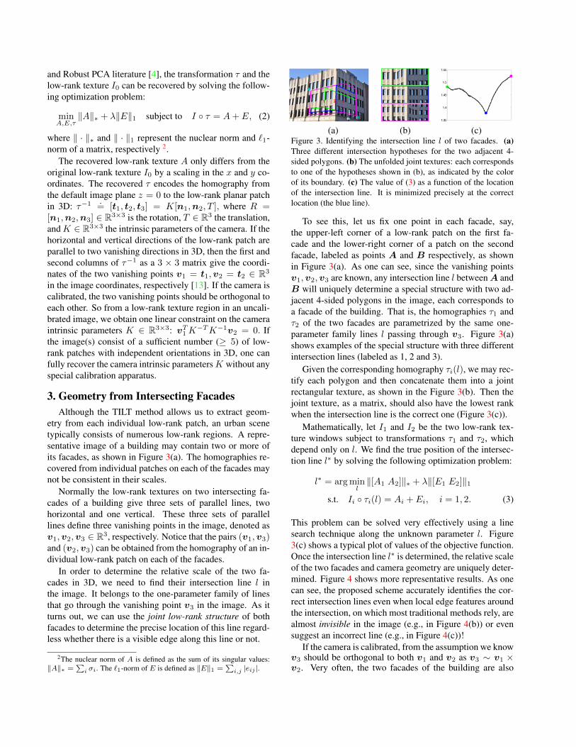
(a) (b) (c)Figure 3. Identifying the intersection line l of two facades. (a)Three different intersection hypotheses for the two adjacent 4-sided polygons. (b) The unfolded joint textures: each correspondsto one of the hypotheses shown in (b), as indicated by the colorof its boundary. (c) The value of (3) as a function of the locationof the intersection line. It is minimized precisely at the correctlocation (the blue line).
To see this, let us fix one point in each facade, say,the upper-left corner of a low-rank patch on the first fa-cade and the lower-right corner of a patch on the secondfacade, labeled as points A and B respectively, as shownin Figure 3(a). As one can see, since the vanishing pointsv1,v2,v3 are known, any intersection line l between A andB will uniquely determine a special structure with two ad-jacent 4-sided polygons in the image, each corresponds toa facade of the building. That is, the homographies τ1 andτ2 of the two facades are parametrized by the same one-parameter family lines l passing through v3. Figure 3(a)shows examples of the special structure with three differentintersection lines (labeled as 1, 2 and 3).
Given the corresponding homography τi(l), we may rec-tify each polygon and then concatenate them into a jointrectangular texture, as shown in the Figure 3(b). Then thejoint texture, as a matrix, should also have the lowest rankwhen the intersection line is the correct one (Figure 3(c)).
Mathematically, let I1 and I2 be the two low-rank tex-ture windows subject to transformations τ1 and τ2, whichdepend only on l. We find the true position of the intersec-tion line l∗ by solving the following optimization problem:
l∗ = arg minl‖[A1 A2]‖∗ + λ‖[E1 E2]‖1
s.t. Ii ◦ τi(l) = Ai + Ei, i = 1, 2. (3)
This problem can be solved very effectively using a linesearch technique along the unknown parameter l. Figure3(c) shows a typical plot of values of the objective function.Once the intersection line l∗ is determined, the relative scaleof the two facades and camera geometry are uniquely deter-mined. Figure 4 shows more representative results. As onecan see, the proposed scheme accurately identifies the cor-rect intersection lines even when local edge features aroundthe intersection, on which most traditional methods rely, arealmost invisible in the image (e.g., in Figure 4(b)) or evensuggest an incorrect line (e.g., in Figure 4(c))!
If the camera is calibrated, from the assumption we knowv3 should be orthogonal to both v1 and v2 as v3 ∼ v1 ×v2. Very often, the two facades of the building are also

(a) (b) (c) (d)Figure 4. (a)–(c): Additional representative results of identifying the intersection line of two adjacent facades. Red windows are theinitialization. (d): Accurate 3D “pop-up” from the single image in Figure 3. Camera position is recovered, shown as a small pyramid.
orthogonal to each other, i.e., v1 ⊥ v2.3 If the camerais not calibrated, the three vanishing points impose threeindependent constraints on the camera intrinsic parameters:
vT1K−TK−1v2 = 0,vT
1K−TK−1v3 = 0,vT
2K−TK−1v3 = 0.
This allows us to fully calibrate the camera from just a pairof intersecting facades, if only the focus length f and prin-cipal point (ox, oy) are not known in K. An example ofsuch reconstruction from single image is shown in Figure 4(d).
4. Segmenting Building FacadesPatches of low-rank textures allow us to extract from a
single image accurate information about the camera loca-tion, calibration, and 2D textures and 3D structures. Butin order to obtain a complete 3D model from multiple im-ages around a large building, we need to establish correct,precise point-wise correspondence between different views.
Repetitive features and patterns in an urban scene makefinding the correct correspondence between images muchmore challenging than that for a generic non-urban scene.The reason is obvious: Matching local features or even localpatches are inherently ambiguous – there are many otherpoints and patches in the other image(s) that have exactlythe same local appearance. Most SFM methods then rely onhaving images taken with relatively small baselines, eitherfrom a video sequence or from a very dense set of photos.
When the baseline between images is large or images aresparse, any effort to eliminate such ambiguity has to rely oncertain global spatial relationships among multiple points,lines, or patches. The approach we propose here relies on avery simple observation: the larger the patch or region wematch, the less the ambiguity [24, 23]. To the extreme, ifwe can detect the entire facades, then the matching wouldhave minimal ambiguity. Hence, a necessary step to estab-lish globally consistent correspondence between views is tosegment out each building facade.
As different facades of the same building often have thesame local color and textural appearance (see Figure 4),global geometry and texture become the only cues to tell
3This may not always be the case. For instance, the facades in Figure 9(a) and (b) are not orthogonal.
them apart. Our approach relies on another simple ob-servation: if two adjacent patches, say I1, I2, belong tothe same facade, then after we merge them into a largerpatch I = [I1, I2], the joint texture should remain low-rank (after rectification by a homography found by TILT:I ◦ τ = A + E). Such a patch I can be represented verycompactly by the triplet (A,E, τ): the homography τ , thelow-rank componentA, and the sparse componentE. Thus,by comparing the compactness of the representation beforeand after the merging, we can tell whether the two patchesbelong to the same facade or not.
In the rest of the section, we first derive a purely objec-tive measure for the compactness of a patch I based on itscoding length4, and then we show how to use this measureto effectively cluster patches to form facades.
4.1. Compact Coding for Low-rank TexturesA naive way to encode the patch I would be entropy-
coding of the quantized sequence of pixel values in I , asconventional image compression schemes do. However,when rank(A) is small andE sparse, encoding I in terms ofthe triplet (A,E, τ) is far more efficient as both sparse andlow-rank matrices allow efficient coding. In order to get afinite coding length, the components of the triplet must bequantized. Denote the number of bits required to representa quantized real number by f .5 For controlling overall re-construction quality of the patch, we define a distortion pa-rameter ε. No matter how we encode the patch, the decodedtriplet (A, E, τ) must satisfy a distortion tolerance:
‖(A+ E) ◦ τ−1 − I‖2F ≤ ε2size(I), (4)
where size(I) is the number of pixels of I , say m× n.
Encoding the Sparse Matrix E. The sparsity in E im-plies that it has a very low-entropy – many entries are zero.It has long been observed empirically in signal processing
4There is a theoretical connection between rank and the coding lengthof a matrix [19]. However, rank is very sensitive to noise and outliers. Wehave conducted experiments using the aggregated rank, and the segmenta-tion results are unstable. The proposed coding length is essentially a robustmeasure of rank based on Robust PCA of the image region.
5 We have empirically observed that for any real number, 16 bits aremore than sufficient to ensure a good precision. For example, the homog-raphy τ is a 3 × 3 matrix. Thus, it is sufficient for us to assign 9f bits toit, i.e. L(τ) = 9f , where τ is the quantized τ .
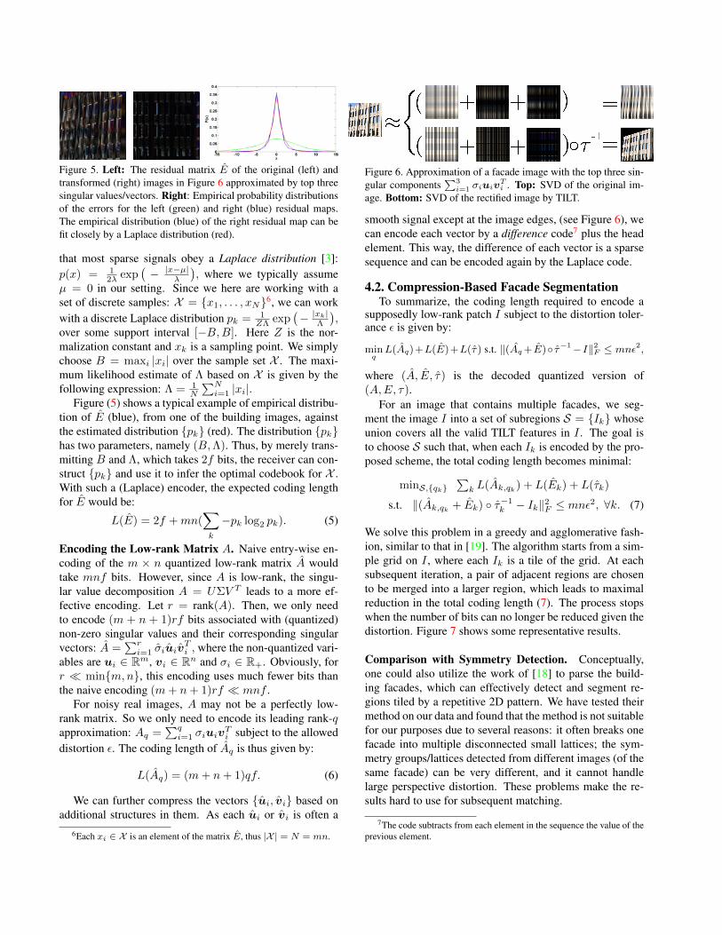
Figure 5. Left: The residual matrix E of the original (left) andtransformed (right) images in Figure 6 approximated by top threesingular values/vectors. Right: Empirical probability distributionsof the errors for the left (green) and right (blue) residual maps.The empirical distribution (blue) of the right residual map can befit closely by a Laplace distribution (red).
that most sparse signals obey a Laplace distribution [3]:p(x) = 1
2λ exp(− |x−µ|
λ
), where we typically assume
µ = 0 in our setting. Since we here are working with aset of discrete samples: X = {x1, . . . , xN}6, we can workwith a discrete Laplace distribution pk = 1
ZΛ exp(− |xk|
Λ
),
over some support interval [−B,B]. Here Z is the nor-malization constant and xk is a sampling point. We simplychoose B = maxi |xi| over the sample set X . The maxi-mum likelihood estimate of Λ based on X is given by thefollowing expression: Λ = 1
N
∑Ni=1 |xi|.
Figure (5) shows a typical example of empirical distribu-tion of E (blue), from one of the building images, againstthe estimated distribution {pk} (red). The distribution {pk}has two parameters, namely (B,Λ). Thus, by merely trans-mitting B and Λ, which takes 2f bits, the receiver can con-struct {pk} and use it to infer the optimal codebook for X .With such a (Laplace) encoder, the expected coding lengthfor E would be:
L(E) = 2f +mn(∑k
−pk log2 pk). (5)
Encoding the Low-rank Matrix A. Naive entry-wise en-coding of the m × n quantized low-rank matrix A wouldtake mnf bits. However, since A is low-rank, the singu-lar value decomposition A = UΣV T leads to a more ef-fective encoding. Let r = rank(A). Then, we only needto encode (m + n + 1)rf bits associated with (quantized)non-zero singular values and their corresponding singularvectors: A =
∑ri=1 σiuiv
Ti , where the non-quantized vari-
ables are ui ∈ Rm, vi ∈ Rn and σi ∈ R+. Obviously, forr � min{m,n}, this encoding uses much fewer bits thanthe naive encoding (m+ n+ 1)rf � mnf .
For noisy real images, A may not be a perfectly low-rank matrix. So we only need to encode its leading rank-qapproximation: Aq =
∑qi=1 σiuiv
Ti subject to the allowed
distortion ε. The coding length of Aq is thus given by:
L(Aq) = (m+ n+ 1)qf. (6)
We can further compress the vectors {ui, vi} based onadditional structures in them. As each ui or vi is often a
6Each xi ∈ X is an element of the matrix E, thus |X | = N = mn.
Figure 6. Approximation of a facade image with the top three sin-gular components
∑3i=1 σiuiv
Ti . Top: SVD of the original im-
age. Bottom: SVD of the rectified image by TILT.
smooth signal except at the image edges, (see Figure 6), wecan encode each vector by a difference code7 plus the headelement. This way, the difference of each vector is a sparsesequence and can be encoded again by the Laplace code.
4.2. Compression-Based Facade SegmentationTo summarize, the coding length required to encode a
supposedly low-rank patch I subject to the distortion toler-ance ε is given by:
minqL(Aq)+L(E)+L(τ) s.t. ‖(Aq+E)◦ τ−1−I‖2F ≤ mnε2,
where (A, E, τ) is the decoded quantized version of(A,E, τ).
For an image that contains multiple facades, we seg-ment the image I into a set of subregions S = {Ik} whoseunion covers all the valid TILT features in I . The goal isto choose S such that, when each Ik is encoded by the pro-posed scheme, the total coding length becomes minimal:
minS,{qk}∑k L(Ak,qk) + L(Ek) + L(τk)
s.t. ‖(Ak,qk + Ek) ◦ τ−1k − Ik‖2F ≤ mnε2, ∀k. (7)
We solve this problem in a greedy and agglomerative fash-ion, similar to that in [19]. The algorithm starts from a sim-ple grid on I , where each Ik is a tile of the grid. At eachsubsequent iteration, a pair of adjacent regions are chosento be merged into a larger region, which leads to maximalreduction in the total coding length (7). The process stopswhen the number of bits can no longer be reduced given thedistortion. Figure 7 shows some representative results.
Comparison with Symmetry Detection. Conceptually,one could also utilize the work of [18] to parse the build-ing facades, which can effectively detect and segment re-gions tiled by a repetitive 2D pattern. We have tested theirmethod on our data and found that the method is not suitablefor our purposes due to several reasons: it often breaks onefacade into multiple disconnected small lattices; the sym-metry groups/lattices detected from different images (of thesame facade) can be very different, and it cannot handlelarge perspective distortion. These problems make the re-sults hard to use for subsequent matching.
7The code subtracts from each element in the sequence the value of theprevious element.
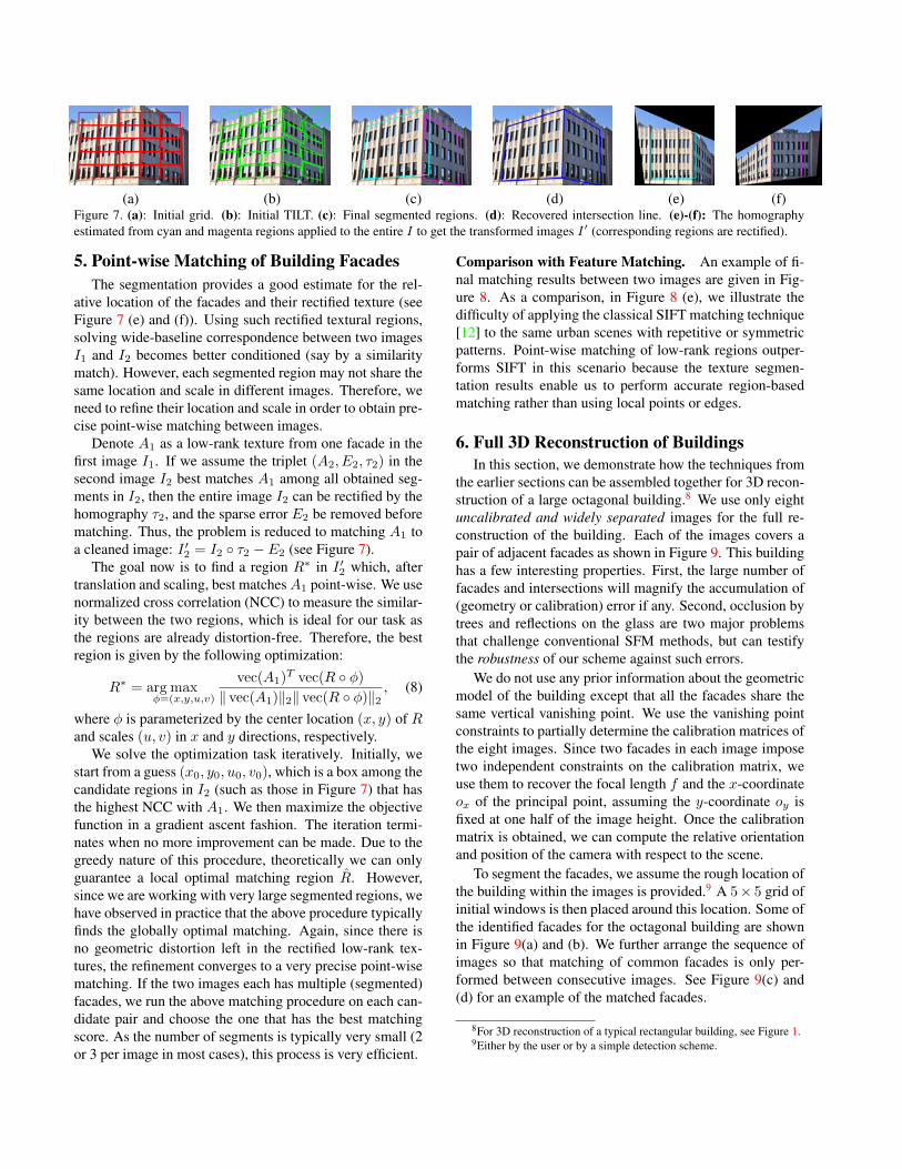
(a) (b) (c) (d) (e) (f)Figure 7. (a): Initial grid. (b): Initial TILT. (c): Final segmented regions. (d): Recovered intersection line. (e)-(f): The homographyestimated from cyan and magenta regions applied to the entire I to get the transformed images I ′ (corresponding regions are rectified).
5. Point-wise Matching of Building FacadesThe segmentation provides a good estimate for the rel-
ative location of the facades and their rectified texture (seeFigure 7 (e) and (f)). Using such rectified textural regions,solving wide-baseline correspondence between two imagesI1 and I2 becomes better conditioned (say by a similaritymatch). However, each segmented region may not share thesame location and scale in different images. Therefore, weneed to refine their location and scale in order to obtain pre-cise point-wise matching between images.
Denote A1 as a low-rank texture from one facade in thefirst image I1. If we assume the triplet (A2, E2, τ2) in thesecond image I2 best matches A1 among all obtained seg-ments in I2, then the entire image I2 can be rectified by thehomography τ2, and the sparse error E2 be removed beforematching. Thus, the problem is reduced to matching A1 toa cleaned image: I ′2 = I2 ◦ τ2 − E2 (see Figure 7).
The goal now is to find a region R∗ in I ′2 which, aftertranslation and scaling, best matchesA1 point-wise. We usenormalized cross correlation (NCC) to measure the similar-ity between the two regions, which is ideal for our task asthe regions are already distortion-free. Therefore, the bestregion is given by the following optimization:
R∗ = arg maxφ=(x,y,u,v)
vec(A1)T vec(R ◦ φ)
‖ vec(A1)‖2‖ vec(R ◦ φ)‖2, (8)
where φ is parameterized by the center location (x, y) of Rand scales (u, v) in x and y directions, respectively.
We solve the optimization task iteratively. Initially, westart from a guess (x0, y0, u0, v0), which is a box among thecandidate regions in I2 (such as those in Figure 7) that hasthe highest NCC with A1. We then maximize the objectivefunction in a gradient ascent fashion. The iteration termi-nates when no more improvement can be made. Due to thegreedy nature of this procedure, theoretically we can onlyguarantee a local optimal matching region R. However,since we are working with very large segmented regions, wehave observed in practice that the above procedure typicallyfinds the globally optimal matching. Again, since there isno geometric distortion left in the rectified low-rank tex-tures, the refinement converges to a very precise point-wisematching. If the two images each has multiple (segmented)facades, we run the above matching procedure on each can-didate pair and choose the one that has the best matchingscore. As the number of segments is typically very small (2or 3 per image in most cases), this process is very efficient.
Comparison with Feature Matching. An example of fi-nal matching results between two images are given in Fig-ure 8. As a comparison, in Figure 8 (e), we illustrate thedifficulty of applying the classical SIFT matching technique[12] to the same urban scenes with repetitive or symmetricpatterns. Point-wise matching of low-rank regions outper-forms SIFT in this scenario because the texture segmen-tation results enable us to perform accurate region-basedmatching rather than using local points or edges.
6. Full 3D Reconstruction of BuildingsIn this section, we demonstrate how the techniques from
the earlier sections can be assembled together for 3D recon-struction of a large octagonal building.8 We use only eightuncalibrated and widely separated images for the full re-construction of the building. Each of the images covers apair of adjacent facades as shown in Figure 9. This buildinghas a few interesting properties. First, the large number offacades and intersections will magnify the accumulation of(geometry or calibration) error if any. Second, occlusion bytrees and reflections on the glass are two major problemsthat challenge conventional SFM methods, but can testifythe robustness of our scheme against such errors.
We do not use any prior information about the geometricmodel of the building except that all the facades share thesame vertical vanishing point. We use the vanishing pointconstraints to partially determine the calibration matrices ofthe eight images. Since two facades in each image imposetwo independent constraints on the calibration matrix, weuse them to recover the focal length f and the x-coordinateox of the principal point, assuming the y-coordinate oy isfixed at one half of the image height. Once the calibrationmatrix is obtained, we can compute the relative orientationand position of the camera with respect to the scene.
To segment the facades, we assume the rough location ofthe building within the images is provided.9 A 5× 5 grid ofinitial windows is then placed around this location. Some ofthe identified facades for the octagonal building are shownin Figure 9(a) and (b). We further arrange the sequence ofimages so that matching of common facades is only per-formed between consecutive images. See Figure 9(c) and(d) for an example of the matched facades.
8For 3D reconstruction of a typical rectangular building, see Figure 1.9Either by the user or by a simple detection scheme.

(a) (b) (c) (d) (e)Figure 8. (a) Segmented and unwarped facade. (b),(c), Segmented and unwarped region of the same facade in a different image. In (c),the segmentation result is further refined to the orange box by matching. (d) Point-wise match between two regions of the facades. (e)Feature-point matching result of the two rectified regions by SIFT [12], with red lines indicate mismatches.
(a) (b) (c) (d) (e) (f)Figure 9. (a) and (b): Segmentation (green) and intersection detection (blue) on two images of an octagonal building. (c) and (d): A pairof matched regions from the same facade with different partial occlusion. (e): A top view of the reconstructed structures of the octagonalbuilding showing the accumulated geometry error when assembling the views one by one. (f): The parameterized 3D model of the building.
Now we can obtain a full 3D reconstruction by assem-bling the building one view at a time using consecutivelymatched facades. However, errors in both camera parame-ters and the 3D model, when estimated from real images,are inevitable. For example, the camera calibration may notbe precise enough because of simplifying assumptions onthe parameters (i.e., f, ox, oy). Thus, if we assemble theviews one by one, geometric error accumulates as the num-ber of images increases. For example, the start and the endof the model do not meet each other in Figure 9(e).
Enforcing Global Consistency. For global consistency,we propose a global objective, which uses the current cam-era parameters and 3D model as the input, and tries to refinethem simultaneously. Conceptually, this is similar to “bun-dle adjustment” in conventional SFM.
We randomly select two adjacent facades, say the pair inFigure 9(a), and choose the origin of the world frame to be apoint at the intersection of the two facades. In addition, welet the x and y axes of the world frame to be parallel to theleft facade in that image. Once the world frame is chosen,a building with n facades can be described using a set ofn points X = {Xi}ni=1, where each Xi = (xi, 0, zi)
T is(1) on the plane y = 0 and (2) at the intersection line oftwo adjacent facades. These points form a n-sided polygonon the y = 0 plane. For example, the 3D model of theoctagonal building (n = 8) is shown in Figure 9(f).
For the cameras, we use the same set of parameters{Ki, Ri, Ti}ni=1 as before. Here we assume both the focallength fi and the principal point (oxi , oyi) of each cameraare unknown. Now we formulate the global optimization asfollows. First, from each image Ii, we can extract two recti-fied facades (Aji , E
ji ), 1 ≤ j ≤ 2: Ii ◦ τ ji (Ki, Ri, Ti, X) =
Aji + Eji . Second, we ask the i-th pair of matching facadesto be the same, up to some sparse error ei:
Ii ◦ τ2i (Ki, Ri, Ti, X) = Ii′ ◦ τ1i′(Ki′ , Ri′ , Ti′ , X) + ei, (9)
where i′ = mod (i+ 1, n). Combining these two criteria,we propose to solve the following problem:
min
n∑i=1
2∑j=1
{‖Aj
i‖∗ + λ‖Eji ‖1}+
n∑i=1
γ‖ei‖1,
s.t. Ii ◦ τ ji (Ki, Ri, Ti, X) = Aji + Ej
i ,
Ii ◦ τ2i (Ki, Ri, Ti, X) = Ii′ ◦ τ1i′(Ki′ , Ri′ , Ti′ , X) + ei, (10)
where λ and γ are the weights of the respective term. Todeal with the nonlinear constraints in (10), we use an itera-tive scheme, which repeatedly solves the linearized versionof (10) w.r.t the current estimates of all unknown parame-ters (Ki, Ri, Ti, Xi)
ni=1. To reduce the effect of change in
illumination and contrast, we normalize each Ii ◦ τ ji to zeromean and unit Frobenius norm. With the initialization ob-tained from assembling the views one by one, the iterativescheme usually converges in 15 to 20 iterations.
Figure 10 shows the reconstructed full 3D model as wellas the recovered camera poses. The readers should note theimprovement in the top view of the 3D model, compared toFigure 9(e). We also calculated the average error in the eightangles between the building facades. It is 3.1 degree and 1.5degree before and after global adjustment, respectively. Asone can see, despite unknown calibration, partial occlusion,large baselines, our method is able to recover a very preciseand complete 3D model of the building.
Comparison with other SFM Systems. It is difficult tomake a fair comparison between the proposed approach andother SFM methods, since the large baselines and rich sym-metry makes other methods fail. In fact, we tested oursequences on almost all publicly available SFM packagessuch as Bundler [21], SFM-SIFT 10 (which combines Torr’sSFM toolbox [22] with SIFT feature detector [12]), FIT3D
10http://homepages.inf.ed.ac.uk/s0346435/projects/sfm/sfm_sift.html

Figure 10. Frontal (left & middle) and top (right) views of the recovered building. Each pyramid shows the estimated location of a camera.
[5], and Voodoo Camera Tracker 11. All these packagesreport errors related to their inability of establishing mean-ingful correspondence across the views.
7. AcknowledgementThis research was in part supported by ARO MURI
W911NF-06-1-0076, ARL MAST-CTA W911NF-08-2-0004, ONR N00014-09-1-0230, NSF CCF 09-64215, NSFIIS 11-16012 and DARPA KECoM 10036-100471. HosseinMobahi is supported by CSE Ph.D fellowship of UIUC. Theviews and conclusions contained in this document are thoseof the authors and should not be interpreted as represent-ing the official policies, either expressed or implied, of theArmy Research Laboratory or U.S. Government. The U.S.Government is authorized to reproduce and distribute forGovernment purposes notwithstanding any copyright nota-tion hereon.
References[1] A. Akbarzadeh, J.-M. Frahm, P. Mordohai, B. Clipp, C. En-
gels, D. Gallup, P. Merrell, M. Phelps, S. Sinha, B. Tal-ton, L. Wang, Q. Yang, H. Steweius, R. Yang, G. Welch,H. Towles, D. Niste, and M. Pollefeys. Towards urban 3dreconstruction from video. In 3DPVT. 1
[2] H. Bay, A. Ess, T. Tuytelaars, and L. Van Gool. Speeded uprobust features. CVIU, 110(3):346–359, 2008. 1
[3] A. Bruckstein, D. Donoho, and M. Elad. From sparse solu-tions of systems of equations to sparse modeling of signalsand images. SIAM Review, 51(1):34–81, 2009. 5
[4] E. Candes, X. Li, Y. Ma, and J. Wright. Robust principalcomponent analysis? arXiv, 2009. 3
[5] I. Esteban, J. Dijk, and F. Groen. Fit3d toolbox: multipleview geometry and 3d reconstruction for matlab. In Interna-tional Symposium on Security and Defence Europe (SPIE),2010. 8
[6] J. Frahm, P. Fite-Georgel, D. Gallup, T. Johnson, R. Ragu-ram, C. Wu, Y. Jen, E. Dunn, B. Clipp, S. Lazebnik, andM. Pollefeys. Building Rome on a cloudless day. In ECCV,2010. 1
[7] S. Gould, R. Fulton, and D. Koller. Decomposing a sceneinto geometric and semantically consistent regions. In ICCV,2009. 1
[8] A. Gupta, A. Efros, and M. Hebert. Blocks world revis-ited: image understanding using qualitative geometry andmechanics. In ECCV, 2010. 2
11http://www.digilab.uni-hannover.de/docs/manual.html
[9] K. Huang, A. Yang, W. Hong, and Y. Ma. Large baselinematching and reconstruction from symmetry cells. In ICRA,2004. 2
[10] D. Lee, M. Hebert, and T. Kanade. Geometric reasoning forsingle image structure recovery. In CVPR, 2009. 2
[11] Y. Liu, H. Hel-Or, C. Kaplan, and L. van Gool. Computa-tional symmetry in computer vision and computer graphics.FTCGV, 5:1–197, 2010. 1
[12] D. Lowe. Object recognition from local scale-invariant fea-tures. In ICCV, 1999. 1, 6, 7
[13] Y. Ma, J. Kosecka, S. Soatto, and S. Sastry. An Invitation to3-D Vision, From Images to Models. Springer-Verlag, NewYork, 2004. 3
[14] J. Matas, O. Chum, M. Urba, and T. Pajdla. Robust widebaseline stereo from maximally stable extremal regions. InBMVC, pages 384–396, 2002. 1
[15] K. Mikolajczyk, T. Tuytelaars, C. Schmid, A. Zisserman,J. Matas, F. Schaffalitzky, T. Kadir, and L. Van Gool. Acomparison of affine region detectors. IJCV, 65(1–2):43–72,2005. 1
[16] B. Micusık and J. Kosecka. Piecewise planar city 3D mod-eling from street view panaramic sequences. In ICCV, 2009.1
[17] B. Micusık, H. Wildenauer, and J. Kosecka. Detection andmatching of rectilinear structures. In CVPR, 2008. 1
[18] M. Park, K. Brocklehurst, R. Collins, and Y. Liu. Deformedlattice detection in real-world images using mean-shift be-lief propagation. IEEE Transactions on Pattern Analysis andMachine Intelligence, 31(1), October 2009. 1, 5
[19] S. Rao, H. Mobahi, A. Yang, S. Sastry, and Y. Ma. Natu-ral image segmentation with adaptive texture and boundaryencoding. In ACCV, 2009. 4, 5
[20] A. Saxena, M. Sun, and A. Ng. Make3D: Learning 3D scenestructure from a single still image. PAMI, 2009. 2
[21] N. Snavely, S. Seitz, and R. Szeliski. Modeling the worldfrom internet photo collections. IJCV, 80:189–210, 2008. 1,7
[22] P. Torr. Geometric motion segmentation and model selection.Philosophical Transactions of the Royal Society of London,356(1740):1321–1340, 1998. 7
[23] J. Cech, J. Matas, and M. Perdoch. Efficient sequential corre-spondence selection by cosegmentation. PAMI, 32(9):1568–1581, 2010. 4
[24] A. Vedaldi and S. Soatto. Local features, all grown up. InCVPR, 2006. 4
[25] Z. Zhang, X. Liang, A. Ganesh, and Y. Ma. TILT: transforminvariant low-rank textures. In ACCV, 2010. 2
[26] S. Zhu and D. Mumford. A stochastic grammar of images.FTCGV, 2006. 1