Hitachi UCP 2000 for VMware vSphere with VMware Site … · 2019-09-15 · Figure 5 provides a...
50
June 2017 By Tsuyoshi Inoue Reference Architecture Guide Hitachi Unified Compute Platform 2000 for VMware vSphere with VMware Site Recovery Manager Solution using Stretched Storage (Global-Active Device)
Transcript of Hitachi UCP 2000 for VMware vSphere with VMware Site … · 2019-09-15 · Figure 5 provides a...

June 2017
By Tsuyoshi Inoue
Reference Architecture Guide
Hitachi Unified Compute Platform 2000 for VMware vSphere with VMware Site Recovery Manager Solution using Stretched Storage (Global-Active Device)

FeedbackHitachi Data Systems welcomes your feedback. Please share your thoughts by sending an email message to [email protected]. To assist the routing of this message, use the paper number in the subject and the title of this white paper in the text.
Revision History
Revision Changes Date
AS-600-00 Initial release June, 2017

Table of ContentsSolution Overview .......................................................................................................................................................... 1
VMware Site Recovery Manager 6.1 .............................................................................................................................. 3
Stretched Storage with Global-Active Device for VMware Site Recovery Manager 6.1.............................................. 3
Solution Components................................................................................................................................................... 8
Hardware Components................................................................................................................................................... 8
Software Components.................................................................................................................................................. 11
Solution Design............................................................................................................................................................ 14
Compute Architecture................................................................................................................................................... 15
Storage Architecture..................................................................................................................................................... 15
Management Architecture ........................................................................................................................................... 21
Configuring and Managing Array Manager and Array Pair with Stretched Storage Leveraging Global-Active Device ............................................................................................................................................................................ 23
Defining Volume Pair Relationship................................................................................................................................ 23
Pair Creation with Global-Active Device using Command Control Interface .............................................................. 25
Pair Management with Global-Active Device ............................................................................................................... 25
Global-active device Volume Path Management on ESXi Host ................................................................................... 27
Disaster Recovery and Replication Control Components ............................................................................................ 30
Solution Validation...................................................................................................................................................... 33
Test Methodology ........................................................................................................................................................ 33
Test Results ................................................................................................................................................................... 39

1
Hitachi Unified Compute Platform 2000 for VMware vSphere with VMware Site Recovery Manager Solution using Stretched Storage (Global-Active Device)
Reference Architecture Guide
VMware Site Recovery Manager 6.1 supports a new feature that helps eliminate downtime for planned migration across sites leveraging Cross-vCenter vMotion and Stretched Storage while providing the following comprehensive Disaster Recovery Orchestration and Solutions.
VMware Site Recovery Manager 6.1 features:
Planned maintenance downtime avoidance
Zero-downtime disaster avoidance
Non-disruptive automated testing
Automated recovery plan orchestration
Management Resiliency
Hitachi Storage Replication Adapter 2.2.0 supports Stretched Storage with VMware Site Recovery Manager 6.1, leveraging global-active device which provides a single stretched volume across the data center.
This paper shows the pre-designed, pre-configured, and pre-validated solution as a reference architecture that is comprised of both a VMware Site Recovery Manager stack and Stretched Storage, stack leveraging Hitachi Storage Replication Adapter 2.2.0 and global-active device on Unified Compute Platform 2000 for VMware vSphere.
Solution Overview
This reference architecture guide describes a business continuity and disaster recovery solution to protect a VMware vSphere virtualized data center. The infrastructure is built on the Hitachi Unified Compute Platform 2000 for VMware vSphere.
Hitachi Unified Compute Platform 2000 for VMware vSphere is an entry level converged infrastructure. A converged infrastructure is a single, optimized platform that combines compute, storage, and networking. It brings tremendous flexibility and scalability to manage, monitor, and provision virtual machine resources in the data center.
For more information about the Hitachi Unified Compute Platform 2000 for VMware vSphere, please refer to the following document:
Hitachi Unified Compute Platform 2000 for VMware vSphere Reference Architecture Guide
https://www.hds.com/en-us/pdf/white-paper/hitachi-ucp-2000-for-vmware-vsphere.pdf
Figure 1 shows the components overview of this reference architecture. Please refer to the "VMware Site Recovery Manager 6.1" section and the "Stretched Storage with Global-Active Device for VMware Site Recovery Manager 6.1" section for the core components. Please refer to the "Software Components" section for the other components.
1

2
Figure 1
This reference architecture guide contains solution configurations, components, and a validated solution for use by IT architects, IT administrators, and others involved in data center planning and design of VMware vSphere infrastructures.
You need some familiarity with the following:
Hitachi Virtual Storage Platform Gx00 models
global-active device
Hitachi Storage Navigator
Hitachi Command Suite
Hitachi Dynamic Link Manager
Hitachi Storage Replication Adapter
Hitachi Command Control Interface
Brocade Switches
VMware ESXi 6.0U2
VMware vCenter 6.0U2
VMware vCenter Site Recovery Manager 6.1
2
3
Note — Testing of this configuration was in a lab environment. Many things affect production environments beyond prediction or duplication in a lab environment. Please follow the recommended practice of conducting proof-of-concept testing for acceptable results in a non-production, isolated test environment that matches your production environment before your production implementation of this solution.
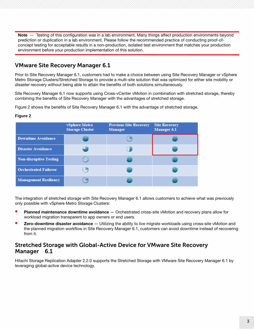
VMware Site Recovery Manager 6.1
Prior to Site Recovery Manager 6.1, customers had to make a choice between using Site Recovery Manager or vSphere Metro Storage Clusters/Stretched Storage to provide a multi-site solution that was optimized for either site mobility or disaster recovery without being able to attain the benefits of both solutions simultaneously.
Site Recovery Manager 6.1 now supports using Cross-vCenter vMotion in combination with stretched storage, thereby combining the benefits of Site Recovery Manager with the advantages of stretched storage.
Figure 2 shows the benefits of Site Recovery Manager 6.1 with the advantage of stretched storage.
Figure 2
The integration of stretched storage with Site Recovery Manager 6.1 allows customers to achieve what was previously only possible with vSphere Metro Storage Clusters:
Planned maintenance downtime avoidance — Orchestrated cross-site vMotion and recovery plans allow for workload migration transparent to app owners or end users.
Zero-downtime disaster avoidance — Utilizing the ability to live migrate workloads using cross-site vMotion and the planned migration workflow in Site Recovery Manager 6.1, customers can avoid downtime instead of recovering from it.
Stretched Storage with Global-Active Device for VMware Site Recovery Manager 6.1
Hitachi Storage Replication Adapter 2.2.0 supports the Stretched Storage with VMware Site Recovery Manager 6.1 by leveraging global-active device technology.
3

4
The following is the difference between traditional Site Recovery Manager (Non-Stretched Storage) and Stretched Storage technology:
Stretched Storage is Active/Active configuration. (Non-Stretched Storage is Active/Passive configuration)
Global-active device provides a host with a single volume from distributed storage by assigning the same virtual LDEV number and the same serial number of storage to both primary volume (P-VOL) and secondary volume (S-VOL), which are carved out from different storage.
VMware Site Recovery Manager 6.1 recognizes this logical volume as Stretched Storage, while also recognizing it as different volumes from different sites through Hitachi Storage Replication Adapter on each site.
I/O requests from the host to a global-active device pair volume are managed according to the volume's I/O mode, such as Local mode and Blocked mode.
Figure 3 shows the overview of the high-level logical design with the disaster recovery solution implemented on VMware Site Recovery Manager 6.1 and global-active device.
4

5
Figure 3
Figure 4 provides a high-level design of the tested Unified Compute Platform 2000 SAN Connect with Virtual Storage Platform G200 (VSP G200), VSP G400, and VSP G600 for VMware vSphere with VMware Site Recovery Manager Solution using Stretched Storage (global-active device) and a single rack base unit.
5

6
Figure 4
Figure 5 provides a high-level design of the scale-out configuration of Unified Compute Platform 2000 SAN Connect with VSP G200, VSP G400, and VSP G600 for VMware vSphere with VMware Site Recovery Manager Solution using Stretched Storage (global-active device) to a single rack fully populated unit.
6

7
Figure 5
Note —This Unified Compute Platform 2000 Appliance is required on both primary and recovery sites. In addition to this, an External storage system for Quorum disk is required to configure global-active device.
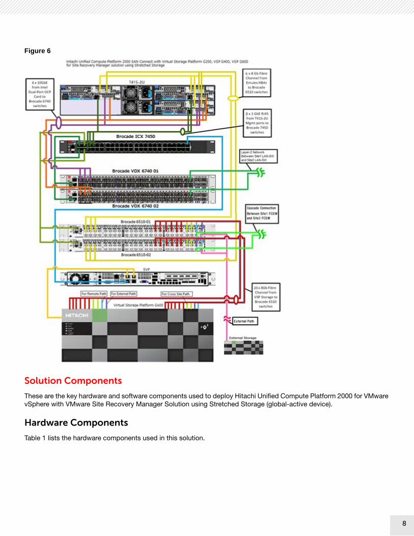
The following are high level diagrams of the Network and SAN Configuration of the Hitachi Unified Compute Platform configurations.
Figure 6 shows Hitachi Unified Compute Platform 2000 SAN Connect with Virtual Storage Platform G200, VSP G400, and VSP G600 for VMware Site Recovery Manager Solution using Stretched Storage (global-active device).
7
8
Figure 6
Solution Components
These are the key hardware and software components used to deploy Hitachi Unified Compute Platform 2000 for VMware vSphere with VMware Site Recovery Manager Solution using Stretched Storage (global-active device).
Hardware Components
Table 1 lists the hardware components used in this solution.
8

9
Note — The following hardware components are required for both the primary site and recovery site.
TABLE 1. HARDWARE COMPONENTS
Hardware Description Version Quantity
Rack Optimized Server for Solutions, 2U Four Node
4-node chassis
2 power supplies
2 Intel Xeon E5-2680 v4 processors, 2.40 GHz
256 GB DDR4-2,133 MHz memory
Emulex LP 12002, 8 Gb/sec dual port PCIe HBA
Intel 82599 10 GbE OCP dual port card
BMC: 3.42.00
BIOS: S2S_3B06
CPLD: 08
CMC: 3.37
Intel 82599 3.7.13.7.14 (inbox driver)
Emulex LPe12002 Boot: 2.20a5
Emulex LPe12002 Firmware: 2.02a0
1
Hitachi Virtual Storage Platform G200 (VSP G200)
Dual controller
16 × 8 Gb/sec Fibre Channel ports
64 GB cache memory
24 × 1.2 TB 10k RPM SAS disks
83-04-02-20/00 1
Hitachi Virtual Storage Platform G400 (VSP G400)
Dual controller
16 × 8 Gb/sec Fibre Channel ports or 8 × 16 Gb/sec Fibre Channel
128 GB cache memory
83-04-02-40/00
Hitachi Virtual Storage Platform G600 (VSP G600)
Dual controller
16 × 8 Gb/sec Fibre Channel ports or 8 × 16 Gb/sec Fibre Channel
256 GB cache memory
83-04-02-40/00
SFF disk tray for expansion (VSP G400, VSP G600)
24 × 1.2 TB 10k RPM SAS disks
Up to 7 disk expansion trays
N/A 1
Brocade VDX 6740 switch 48-port 10 GbE switch nos 7.0.0a 2
Brocade ICX 7450 switch 48-port 1 GbE switch 08.0.30G 1
9

10
Hitachi Virtual Storage Platform Gx00 Models
Hitachi Virtual Storage Platform Gx00 models are based on industry-leading enterprise storage technology. With flash-optimized performance, these systems provide advanced capabilities previously available only in high-end storage arrays. With the Virtual Storage Platform Gx00 models, you can build a high performance, software-defined infrastructure to transform data into valuable information.
Hitachi Storage Virtualization Operating System (SVOS) provides storage virtualization, high availability, superior performance, and advanced data protection for all Virtual Storage Platform Gx00 models. The SVOS software provides common features to consolidate assets, reclaim space, extend life, and reduce migration effort.
New management software improves ease of use to save time and reduce complexity. The infrastructure of Storage Virtualization Operating System creates a management framework for improved IT response to business demands.
Virtual Storage Platform G600 was used to validate this environment. To implement this in your data center, you may use any Virtual Storage Platform G-series storage that supports global-active device.
Brocade
Brocade and Hitachi Data Systems partner to deliver storage networking and data center solutions. These solutions reduce complexity and cost, as well as enable virtualization and cloud computing to increase business agility.
This solution uses the Brocade products listed in Table 2.
Brocade 6505
(VSP G200 only)
24-port 8 Gb/sec Fibre Channel switch
7.4.1d 2
Brocade 6510 (VSP G400, VSP G600 configurations)
48-port 16 Gb/sec Fibre Channel switch
7.4.1d 2
TABLE 2. BROCADE SWITCHES USED IN HITACHI UNIFIED COMPUTE PLATFORM 2000 CONFIGURATIONS
Model Ports Description
MGMT ICX 7450 48 × 1 Gb/sec Ethernet
Rack mounted switch that delivers the performance, flexibility, and scalability require for enterprise gigabit Ethernet access deployment.
LAN VDX 6740 48 × 10 Gb/sec Ethernet
10 GbE rack mounted switch that delivers high performance and reduces network congestion with low latency, and deep buffers.
Fibre Channel
6505
(VSP G200 only)
24 × 8 Gb/sec Fibre Channel
8 Gb/sec Fibre Channel rack mounted switch that delivers reliable and high performance storage area network.
Fibre Channel
6510
(VSP G400, VSP G600)
48 × 16 Gb/sec Fibre Channel
16 Gb/sec Fibre Channel rack mounted switch that delivers reliable and high performance storage area network.
TABLE 1. HARDWARE COMPONENTS (CONTINUED)
Hardware Description Version Quantity
10

11
Software Components
Table 3 lists the main software components used in this solution.
Note — The following software components are required for both the primary and recovery site. Hitachi Local Replication software is required for test recovery in the recovery site.
Hitachi Storage Virtualization Operating System
Hitachi Storage Virtualization Operating System (SVOS) spans and integrates multiple platforms. It integrates storage system software to provide system element management and advanced storage system functions. Used across multiple platforms, Storage Virtualization Operating System includes storage virtualization, thin provisioning, storage service level controls, dynamic provisioning, and performance instrumentation.
TABLE 3. SOFTWARE COMPONENTS
Software Version
Hitachi Storage Virtualization Operating System with Hitachi Dynamic Provisioning
Microcode Dependent
global-active device Microcode Dependent
Hitachi Local Replication
-Hitachi ShadowImage Software
-Hitachi Thin Image Software
Microcode Dependent
Hitachi Storage Navigator Microcode Dependent
VMware ESXi 6.0.0 U2
VMware vCenter Server Appliance
- vCenter Server
- VMware Platform Services Controller
6.0.0 U2
VMware Site Recovery Manager 6.1
Hitachi Storage Replication Adapter 2.2.0
Hitachi Command Control Interface Microcode Dependent
Hitachi Command Suite
- Hitachi Device Manager
- Hitachi Replication Manager
- Hitachi Device Manager Agent
- Hitachi Dynamic Link Manager
- Hitachi Dynamic Link Manager (RMC)
8
11

12
Storage Virtualization Operating System includes standards-based management software on a Hitachi Command Suite (HCS) base. This provides storage configuration and control capabilities for you.
Storage Virtualization Operating System uses Hitachi Dynamic Provisioning (HDP) to provide wide striping and thin provisioning. Dynamic Provisioning provides one or more wide-striping pools across many RAID groups. Each pool has one or more dynamic provisioning virtual volumes (DP-VOLs) without initially allocating any physical space. Deploying Dynamic Provisioning avoids the routine issue of hot spots that occur on logical devices (LDEVs).
Global-active device
Global-active device enables you to create and maintain synchronous, remote copies of data volumes on the Hitachi storage systems. A virtual storage machine is configured in the primary and secondary storage systems using the actual information of the primary storage system, and the global-active device primary and secondary volumes are assigned the same virtual LDEV number in the virtual storage machine. This enables the host to see the pair volumes as a single volume on a single storage system, and both volumes receive the same data from the host.
A quorum disk located in a third and external storage system is used to monitor the global-active device pair volumes. The quorum disk acts as a heartbeat for the global-active device pair, with both storage systems accessing the quorum disk to check on each other. A communication failure between systems results in a series of checks with the quorum disk to identify the problem for the system to be able to receive host updates.
Alternate path software on the host runs in the Active/Active configuration. While this configuration works well at campus distances, at metro distances Hitachi Dynamic Link Manager (HDLM) is required to support preferred/non-preferred paths and ensure that the shortest path is used.
If the host cannot access the primary volume (P-VOL) or secondary volume (S-VOL), host I/O is redirected by the alternate path software to the appropriate volume without any impact to the host applications.
Global-active device provides the following benefits:
Continuous server I/O when a failure prevents access to a data volume
Server failover and failback without storage impact
Load balancing through migration of virtual storage machines without storage impact
VMware vSphere 6.0 U2
VMware vSphere is a virtualization platform that provides a datacenter infrastructure. It features vSphere Distributed Resource Scheduler (DRS), High Availability, and Fault Tolerance.
VMware vSphere has the following components:
ESXi — A hypervisor that loads directly on a physical server. It partitions one physical machine into many virtual machines that share hardware resources.
vCenter Server — Management of the vSphere environment through a single user interface. With vCenter, there are features available such as vMotion, Storage vMotion, Storage Distributed Resource Scheduler, High Availability, and Fault Tolerance.
Platform Services Controller — Platform Services Controller (PSC) is a component of the VMware Cloud Infrastructure Suite. PSC deals with identity management for administrators and applications that interact with the vSphere platform.
Note — Stretched storage is supported only on vCenter Single Sign-On Enhanced Linked Mode environments. Planned migration with Cross vCenter Server vMotion fails if the sites are not in Enhanced Linked Mode. Stretched storage is required when using Cross-vCenter vMotion during a planned migration.
12

13
VMware Site Recovery Manager 6.1
VMware Site Recovery Manager (SRM) is a disaster recovery solution that helps to reduce planned and unplanned downtime of a VMware vSphere infrastructure. It enables automated site recovery and migration processes. This can leverage the built-in vSphere Replication for hypervisor-based replication to cover a wide range of required recovery time and data currency.
This reference architecture focuses on using Site Recovery Manager with storage-based replication technologies using global-active device. This use provides a centralized management of recovery plans. Tight integration between storage systems, VMware vCenter, VMware Site Recovery Manager, and Hitachi Storage Replication Adapter ensure a coordinated recovery for large, business critical environments.
Site Recovery Manager provides automated orchestration of centralized recovery plans for all virtualized applications. Automated orchestration of site failover and failback with a single-click reduces RTOs with reliability.
It also supports minimal impact to business-critical workloads when the following occur:
All ESXi host failure on primary site
All ESXi Fibre Channel path failure on primary site
Storage array component failure on primary site
Primary site failure
Hitachi Storage Replication Adapter 2.2.0
VMware Site Recovery Manager is a VMware application that automates the disaster recovery process using storage-based replication. Storage Replication Adapter (SRA) is the Hitachi interface that integrates Hitachi storage systems and replication software with VMware Site Recovery Manager processes.
Adapter for integrating Site Recovery Manager with the Virtual Storage Platform family.
Supports the Stretched Storage (global-active device) from this version.
This version also supports the Non-Stretched Storage (Universal Replicator and TrueCopy).
Hitachi Command Control Interface
The Command Control Interface (CCI) command-line interface (CLI) software can be used to configure the global-active device environment and create and manage global-active device pairs. CCI is also used to perform disaster recovery procedures.
Hitachi Command Suite
Hitachi Command Suite (HCS) consists of a number of storage management software products used for managing storage resources in large-scale, complex SAN environments. Hitachi Command Suite provides simplified and centralized management through a web-based user interface for global-active device environments. Information from command control interface, such as pair status and global-active device information, passes through Hitachi Device Manager to the Hitachi Command Suite components.
13

14
Hitachi Dynamic Link Manager
Hitachi Dynamic Link Manager (HDLM), used for SAN multipathing, has configurable load balancing policies. These policies automatically select the path having the least amount of input/output processing through all available paths. This balances the load across all available paths, which optimizes IOPS and response time.
The combination of global-active device with Hitachi Dynamic Link Manager enables ESXi hosts to see the primary volume (P-VOL) and secondary volume (S-VOL) as a single LUN.
If the host cannot access the primary volume (P-VOL) or secondary volume (S-VOL), Dynamic Link Manager redirects host I/O to the appropriate volume without any impact to the host applications.
The load balancing function uses VMware vSphere PSPs, or PSPs provided by Hitachi Dynamic Link Manager. The following plug-ins are installed within the pluggable storage architecture (PSA) from VMware on VMKernel:
Storage array type plug-in (SATP)
Path selection plug-in (PSP)
Solution Design
The detailed design for Hitachi Unified Compute Platform 2000 for VMware vSphere with VMware Site Recovery Manager Solution using Stretched Storage (global-active device) includes the following:
Compute Architecture
The basic solution uses one T41S-2U compute chassis.
For a scale-out configuration, up to four T41S-2U compute chassis can be used.
Storage Architecture
The basic solution uses one Hitachi Virtual Storage Platform Gx00 with 24 × 1.2 TB 10K SAS drives to support ESXi Server SAN boot, infrastructure, management, and tenant virtual machines.
For a scale-out configuration, up to seven SFF drive expansion trays can be used. Each tray houses 24 × 2.5 inch disks.
Switch Architecture
The basic solution uses one Brocade ICX 7450 switch for management and two Brocade VDX 6740 switches for local area network.
Hitachi Unified Compute Platform 2000 uses two Brocade 6505 or 6510 switches for redundancy and multipath I/O.
Management Architecture
The management architecture uses the following:
Hitachi Storage Navigator
Hitachi Command Suite
Hitachi Command Control Interface
Hitachi Storage Replication Adapter
VMware vCenter Server
VMware Platform Services Controller
VMware Site Recovery Manager
14

15
Compute Architecture
The tested Hitachi Unified Compute Platform 2000 SAN with Virtual Storage Platform G200, VSP G400, and VSP G600 for VMware vSphere with VMware Site Recovery Manager Solution using Stretched Storage (global-active device) used one T41S-2U compute chassis. The configuration can scale out to support four chassis. Each chassis supports up to four compute nodes.
Storage Architecture
SAN Configuration
This describes the SAN configuration used in this reference architecture.
The SAN configuration for the primary site and recovery site is identical.
Configure two brocade Fibre Channel switches in each site. Each switch is cascade connected to one another between the primary site and recovery site.
Configure the fabric zoning so that each host has redundant paths to each storage system on the other site. The cross-path configuration between the primary site and recovery site is the only supported stretched storage configuration for SRA 2.2.0.
To facilitate copying data between storage systems, configure storage replication links (Remote Paths) between Hitachi Virtual Storage Platform Gx00 on primary site and Hitachi Virtual Storage Platform Gx00 on the recovery site.
Make two Fibre Channel connections from the quorum storage system to each Brocade Fibre Channel switch.
Note#1 —Cross-path configuration is required for this reference architecture.Note#2 — The Remote Path and External Path are required for global-active device.
Figure 7 shows the SAN configuration overview.
15

16
Figure 7
Remote Path (Storage Replication Link)
Two Remote Paths that are configured between the primary site and recovery site provide an alternate path configuration for this validation. At least four paths in total are recommended from a replication multiplexing perspective.
A storage replication link consists of bidirectional ports on the primary storage system connected to a remote-control unit bidirectional port that is defined on the recovery storage system. It represents a bidirectional remote copy connection from the primary data volume (P-VOL) on the primary storage system to the secondary data volume (S-VOL) on the recovery storage system.
Figure 8 shows the Remote Paths management UI on HCS.
Figure 8
External Path
Two External Paths are configured between primary site storage and quorum storage, and between recovery site storage and quorum storage respectively.
16

17
Figure 9 shows the External Paths management UI on HCS.
Figure 9
Figure 10 shows the SAN configuration for the primary site. The recovery site is configured the same. The Fabric data link between the primary and recovery site is configured using Brocade Fibre Channel switches cascade connected with one another across the sites.
Figure 10
17

18
Storage Port Configuration
Table 4 shows the storage port design used for this solution.
TABLE 4. STORAGE PORT CONFIGURATION
Site Compute Chassis Number
Compute Node
Storage Port Purpose
Primary
Site
(Site1)
1 Node 1
(for Management)
1A/4A SAN Boot
5A/8A Management
Node 2
(for Tenant)
2A/3A SAN Boot
6A/7A
(Primary site Storage)
Tenant global-active device P-VOL
1C/4C
(Recovery site Storage)
Tenant global-active device S-VOL
[non-preferred path]
Node 3
(for Tenant)
1B/4B SAN Boot
5A/8B
(Primary site Storage)
Tenant global-active device P-VOL
2C/3C
(Recovery site Storage)
Tenant global-active device S-VOL
[non-preferred path]
Recovery
Site
(Site2)
1 Node 1
(for Management)
1A/4A SAN Boot
5A/8A Management
Node 2
(for Tenant)
2A/3A SAN Boot
1C/4C
(Primary site Storage)
Tenant global-active device P-VOL
[non-preferred path]
6A/7A
(Recovery site Storage)
Tenant global-active device S-VOL
Node 3
(for Tenant)
1B/4B SAN Boot
2C/3C
(Primary site Storage)
Tenant global-active device P-VOL
[non-preferred path]
5A/8B
(Recovery site Storage)
Tenant global-active device S-VOL
18

19
Table 5 shows the storage port properties. The primary and recovery site property values are identical.
RAID Configuration
This solution uses a minimum of 16 × 1.2 TB 10k RPM SAS disks at the primary site. It also uses a minimum of 24 × 1.2 TB 10k RPM SAS disks at the recovery site.
Create a parity group as follows:
One parity group for RAID-10 (2D+2D), using four disks for boot LUNs.
One parity group for RAID-10 (2D+2D), using four disks for infrastructure and management virtual machines.
One parity group for RAID-6 (6D+2P), using eight disks for tenant virtual machines.
One parity group for RAID-6 (6D+2P), using eight disks for test recovery required only for the recovery site storage.
Dynamic pools can be expanded by adding additional parity groups to support additional workloads and virtual machines.
TABLE 5. STORAGE PORT PROPERTIES
Property Value Remarks
Port Attribute Target For Compute Node
Initiator/RCU Target
For Remote Path
External For External Path
Port Security Enabled
Port Speed Auto
Fabric ON
Connection Type P-to-P
19

20
Pool Configuration
Create four dynamic provisioning pools with Hitachi Dynamic Provisioning, as shown in Table 6.
The Dynamic Provisioning pools configuration on the recovery site is identical to the primary site configuration. The LUNs on the recovery site are identical in size to their respective protected LUNs, as required for maintaining the P-VOL and S-VOL relationship. Both the P-VOL and S-VOL LUNs are presented to all ESXi hosts through local and cross-site paths.
Figure 11 shows the dynamic provisioning pool configuration on each storage system.
Figure 11
TABLE 6. DYNAMIC PROVISIONING POOL CONFIGURATION
Dynamic Provisioning
Pool
RAID Number of PGs
Number of
Drives
Capacity DP-Vol Size Purpose
3 RAID-10
(2D+2D)
1 4 2 TB 100 GB x 3 (3 Nodes)
SAN operating system boot
63 RAID-10 (2D+2D) 1 4 2 TB 2 TB x 1 (Management-Vol)
48 MB x 1 (Command Device)
Infrastructure and management virtual machines
5 RAID-6
(6D+2P)
1 8 6 TB 1TB x 2 (global-active device Volume)
Tenant virtual machines
6
(Only Recovery Site Storage)
RAID-6
(6D+2P)
1 8 6 TB 1TB x 2 (SI S-VOL) Tenant virtual machines for test recovery
20

21
Provision one command device LUN in each site:
A command device is a dedicated logical volume on the storage system that functions as the interface to the storage system from a host.
Provision a 48 MB LUN, the smallest LUN that can be created, on both sites.
These LUNs are converted to command devices and presented to the pair management server.
Provision four VMFS LUNs in the implementation of this environment:
Datastore for the SAN operating system boot device LUN (non-replicated) assigned per host
Datastore for storing management virtual machines (non-replicated)
Datastore for storing the operating system (C:) virtual disks of synchronous replication-protected virtual machines by leveraging global-active device
Datastore for storing the data (D:) virtual disks of synchronous replication-protected virtual machines by leveraging global-active device
Note — vSphere 6.0 does not support Cross-vCenter vMotion if a VM belongs to multiple data stores. Attempts to migrate a virtual machine that belongs to more than one data store to a host on a different vCenter Server is not supported in vSphere 6.0. This issue is seen only when you use Change compute resource only as the migrate option. Workaround: Use Change both compute resource and storage as the migrate option.
Management Architecture
Management Server Configuration
Create each management server, as shown in Table 7.
TABLE 7. MANAGEMENT SERVER CONFIGURATION ON EACH SITE
Management Server OS Installed software
VMware common infrastructure Server
SUSE Linux Enterprise 11 64-bit
VMware Platform Services Controller (VCSA)
VMware Management Server SUSE Linux Enterprise 11 64-bit
VMware vCenter Server (VCSA)
Disaster Recovery Management Server
Windows Server 2012 R2 Standard 64-bit
VMware vCenter Site Recovery Manager
Hitachi Storage Replication Adapter
21

22
Note — It is recommended to build independent Pair Management Server for management of global-active device pairs. SRM and SRA support Windows OS only. Configuring independent Pair Management Server with Linux or UNIX OS is required because SRA communicates to independent Pair Management Server by using Telnet or SSH.
Virtual Machine Installation and Configuration
Hitachi Unified Compute Platform 2000 for VMware vSphere requires the use of VMware vCenter.
This can be the UCP 2000 VMware vCenter Server Appliance or an existing VMware vCenter environment.
VMware vCenter Server Systems Configuration
Enhanced Linked Mode connects multiple vCenter Server systems together by using one or more Platform Services Controllers.
To join vCenter Server systems in Enhanced Linked Mode, connect them to the same Platform Services Controller, or to Platform Services Controllers that share the same vCenter Single Sign-On domain.
For this reference architecture, a Platform Services Controller (PSC) is configured in each site, and each PSC Joins in the same vCenter Single Sign-On domain configured across the primary and recovery site.
VMware vCenter Cluster Configuration
All VMware ESXi hosts are members of a single VMware vCenter cluster on each site.
Distributed Resource Scheduler
High Availability
Power Management
Pair Management Server Red Hat Enterprise Linux 7.2 64-bit
Hitachi Command Control Interface
Hitachi Command Suite
- Hitachi Device Manager Agent
Storage Management Server Windows Server 2012 R2 Standard 64-bit
Hitachi Command Suite
- Hitachi Device Manager
- Hitachi Replication Manager
- Hitachi Dynamic Link Manager (RMC)
TABLE 7. MANAGEMENT SERVER CONFIGURATION ON EACH SITE (CONTINUED)
Management Server OS Installed software
22

23
Configuring and Managing Array Manager and Array Pair with Stretched Storage Leveraging Global-Active Device
This section describes the building structure that is needed to take steps from configuring the stretched storage leveraging global-active device to enabling you to recognize and manage the stretched storage from the VMware Site Recovery Manager layer. When configuring array pairs is complete, you can create protection groups to protect tenant virtual machines.
Defining Volume Pair Relationship
A key aspect of this reference architecture using VMware Site Recovery Manager 6.1 on the Hitachi Virtual Storage Platform Gx00 is defining the volume pair relationship for replication between storage systems. Define and manage storage replication relationships through the Hitachi Storage Navigator graphical user interface or a host running Hitachi Open Remote Copy Manager (HORCM).
Hitachi Open Remote Copy Manager is a component of command control interface. It manages replication via a command-line interface by using a command device. For this solution, the command control interface enables Hitachi Storage Replication Adapter to issue Open Remote Copy Manager commands for managing, monitoring, and controlling the replication process initiated by VMware Site Recovery Manager.
Each Open Remote Copy Manager instance installed at the primary and recovery site contains a configuration definition file (horcmx.conf). This file defines the devices in copy pairs. Define the configuration file before starting the Open Remote Copy Manager daemon.
Note —A configuration definition file must be created for each site.
Figure 12 shows an example of horcm0.conf file used for the primary system.
Figure 12
Figure 13 shows an example horcm1.conf file used for the recovery site.
23

24
Figure 13
Note — Only specify mirror unit numbers (MU#) when defining ShadowImage pairs. MU# is described to define it as a P-VOL of local replication (MU#0 is recommended). When a unit number other than MU#0 is described, specify the described MU# in the environment variable, RMSRATMU.
Figure 14 shows an example horcm2.conf file. Following recommended practices, with the even number (horcm2), this file is for the recovery site.
Figure 14
Note — To the configuration definition file (horcmx.conf), make sure to specify the actual LDEV IDs for the global-active device pair volumes, not the virtual LDEV IDs.
24

25
Pair Creation with Global-Active Device using Command Control Interface
Initially, the volumes are in simplex (SMPL) mode. The volumes are not paired and synchronized until running the global-active device paircreate process. After defining volume pair relationships and starting the Hitachi Open Remote Copy Manager daemon, initiate storage replication using Open Remote Copy Manager commands.
For this reference architecture, two datastores (for OS vmdk and for User Data vmdk) are assigned for a single virtual machine.
Use consistency groups in virtual machine configurations where multiple virtual disks reside on different datastores. The consistency group ensures data consistency among multiple datastores assigned to Hitachi device groups. The datastores are maintained in a state of replication consistent with each other.
To register global-active device pairs to a consistency group, specify the -fg option when creating the pair. If you create a pair and do not specify a consistency group ID, the ID for an unused consistency group in the storage system will be automatically assigned.
Create global-active device pairs by using the command control interface command shown below.
In the following example, specify 0 for the quorum disk ID and specify 1 for the consistency group ID to create a global-active device pair.
Example: # paircreate -g VM01_GAD -fg never 1 -vl -jq 0
Figure 15 shows an example of the command and the output of a global-active device pair creation based on the configuration definition file.
Figure 15
Pair Management with Global-Active Device
Global-active device pair management is also available using the Hitachi Command Suite GUI. Use Hitachi Command Suite or command control interface to view and manage storage replication activity after the global-active device pair creation.
25

26
Note — In this reference architecture, global-active device pairs creation was performed by using command control interface commands. Hitachi Command Suite also provides you with a GUI for configuring and managing global-active device stack as follows:
Configure Remote Paths
Configure Quorum Disks
Configure Virtual Storage Machines
Configure DP Pools
Configure Thin Image Pools
Configure Pair Management Servers
Figure 16 shows the global-active device setup wizard in the Hitachi Command Suite graphical user interface.
Figure 16
Hitachi Command Suite GUI also provides you with a single pane of glass for managing global-active device stack.
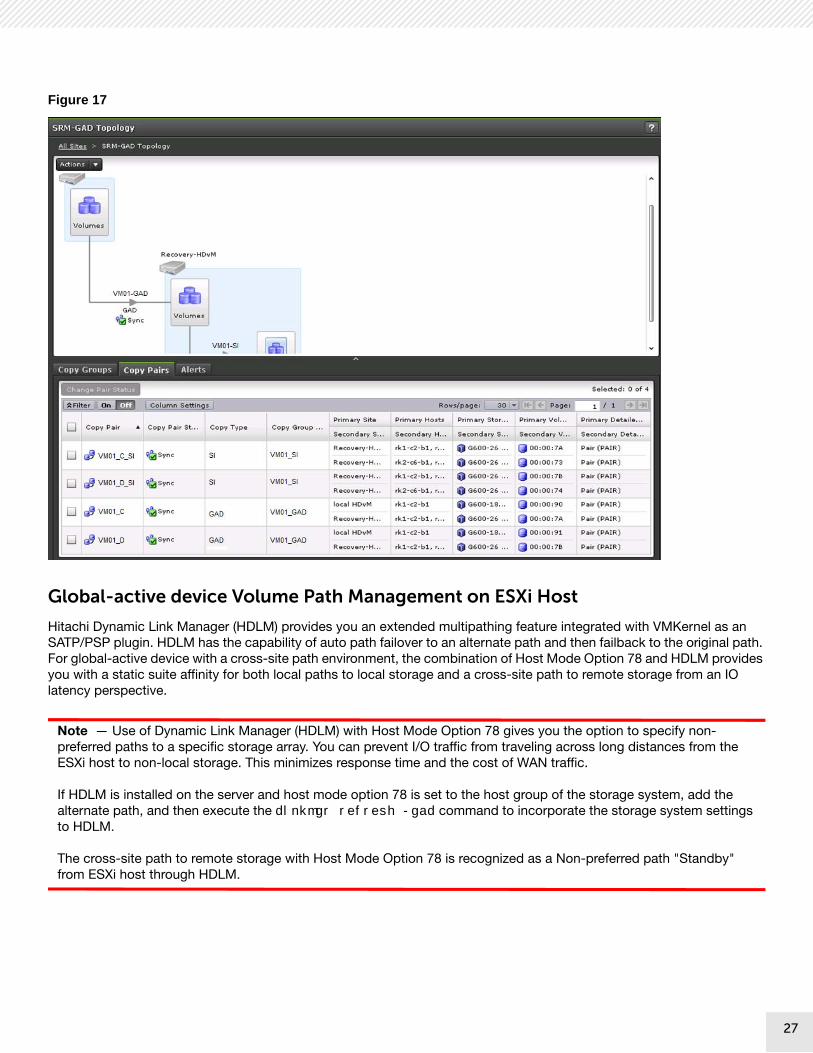
Figure 17 shows the global-active device topology wizard in the Hitachi Command Suite graphical user interface.
26
27
Figure 17
Global-active device Volume Path Management on ESXi Host
Hitachi Dynamic Link Manager (HDLM) provides you an extended multipathing feature integrated with VMKernel as an SATP/PSP plugin. HDLM has the capability of auto path failover to an alternate path and then failback to the original path. For global-active device with a cross-site path environment, the combination of Host Mode Option 78 and HDLM provides you with a static suite affinity for both local paths to local storage and a cross-site path to remote storage from an IO latency perspective.
Note — Use of Dynamic Link Manager (HDLM) with Host Mode Option 78 gives you the option to specify non-preferred paths to a specific storage array. You can prevent I/O traffic from traveling across long distances from the ESXi host to non-local storage. This minimizes response time and the cost of WAN traffic.
If HDLM is installed on the server and host mode option 78 is set to the host group of the storage system, add the alternate path, and then execute the dlnkmgr refresh -gad command to incorporate the storage system settings to HDLM.
The cross-site path to remote storage with Host Mode Option 78 is recognized as a Non-preferred path "Standby" from ESXi host through HDLM.
27

28
Figure 18 shows the cross-path configuration with global-active device used for this reference architecture highlighting HDLM and Host Mode Option 78. The ESXi hosts and storage are connected via Fibre Channel switches.
Figure 18
28

29
Figure 19 shows the path status of global-active device volumes discovered by ESXi hosts.
Figure 19
The following lists the load balancing algorithms that HDLM can use:
Extended Round Robin: HTI_PSP_HDLM_EXRR
Extended Least I/Os: HTI_PSP_HDLM_EXLIO
Extended Least Blocks: HTI_PSP_HDLM_EXLBK
This reference architecture adopts the Extended Round Robin (HTI_PSP_HDLM_EXRR) algorithm. The paths are simply selected in order from among all the connected paths.
29

30
Figure 20 shows a status of Path Selection Policy for global-active device volumes.
Figure 20
Disaster Recovery and Replication Control Components
VMware Site Recovery Manager
Installing VMware Site Recovery Manager is a prerequisite to installing the Hitachi Storage Replication Adapter. This is necessary to ensure that VMware Site Recovery Manager can properly register the installed adapter. After the VMware Site Recovery Manager Server instance is installed, the Site Recovery Manager plug-in appears in the vSphere Web Client. Use this on the protected and recovery sites to configure and manage Site Recovery Manager.
Perform following steps for pairing and mapping objects between sites from VMware Site Recovery Manager:
Step 1. Connect to vSphere Web Client on one of the sites, and select Site Recovery > Sites.
Right-click a site and select Pair Site.
Step 2. Provide following information about the pairing site.
Address of the Platform Services Controller
vCenter Single Sign-On username and password
Step 3. Follow the steps for object mappings between sites.
Create resource mappings
Create folder mappings
Create network mappings
Create storage policy mappings
30

31
Figure 21 shows the status of site pairing on VMware Site Recovery Manager.
Figure 21
Hitachi Storage Replication Adapter
Hitachi Storage Replication Adapter (SRA) is deployed within a VMware Site Recovery Manager environment.
Confirm the SRA version and Stretched SRM status as follows:
Rescan the Storage Replication Adapter from the SRAs at Monitor tab in the Sites object of Site Recovery Manager. Use this to verify the installed Hitachi adapter version and supported array models.
Figure 22 shows the status of Storage Replication Adapter on VMware Site Recovery Manager.
Figure 22
31

32
Register the Array Manager and confirm the following status on Array Manager:
Array Manager is discovered
Discovered Array Manager status shows "enabled"
Local Device (GAD P-VOL) status of the primary site shows “Outgoing (Stretched Storage)”
Local Device (GAD S-VOL) status of the recovery site shows “Incoming (Stretched Storage)”
The property values shown in figure 23 come from defined values on a command control interface configuration definition file (horcmx.conf) through interaction between the SRM and SRA.
Figure 23 shows the status related to Array Pairs on VMware Site Recovery Manager.
Figure 23
32

33
Solution Validation
This describes the test methodology and VMware Site Recovery Manager operations used to validate this solution for Hitachi Unified Compute Platform 2000 for VMware vSphere with VMware Site Recovery Manager Solution using Stretched Storage (global-active device).
The goal of this engineering validation was to perform a holistic validation on the compute, network, and storage components in this solution. This validation ensures that all hardware and software components function together.
Test Methodology
These test scenarios were intended to validate the VMware Site Recovery Manager feature, VMware vSphere feature, and the comprehensive disaster recovery feature aspects of Hitachi Unified Compute Platform 2000 for VMware vSphere con-figured with Hitachi Virtual Storage Platform G600 storage array in a united performance configuration.
These were the steps followed to test the reference architecture of the VMware Site Recovery Manager Solution with Stretched Storage:
1. Create datastore tags and assign them to datastores to associate with a storage policy.
2. If your environment uses Enhanced Linked Mode, create tag categories and tags only on the protected site. The tags are replicated to other vCenter Server instances in Enhanced Linked Mode environments.
3. Create virtual machine storage polices in vCenter Server on both sites, that include the tags that you assigned to the datastores to protect.
4. Associate virtual machines to protect with the appropriate storage policy on the protected site. You must associate all of a virtual machine's disks with the same storage policy.
5. Build the environment and have VMware Site Recovery Manager discover the replicated devices on both sites.
6. Create VMware Site Recovery Manager Storage Policy Protection Groups (SPPG) for the protected virtual machines based on the storage policy where they reside.
7. Create VMware Site Recovery Manager Recovery Plans.
8. Perform the following functions:
Recovery
Re-protect
Recovery (failback)
Test Recovery
Cleanup
9. Use the pairdisplay command in command control interface to verify that each function worked correctly.
Note — Protection groups for stretched storage must be created as storage policy protection groups. Storage policy-based protection groups utilize vSphere tags in combination with vSphere storage policy-based management to enable automated policy-based protection for virtual machines.
33

34
VMware Site Recovery Manager Operations
This describes how each operation for the recovery plan works along with global-active device pairs. The following lists the operations used in this solution.
Recovery
The recovery operation for Site Recovery Manager has two options:
Planned migration
Enable vMotion of eligible VMs — If the "Enable vMotion of eligible VMs" option is selected, Cross vCenter Server vMotion is used for all protected, powered-on virtual machines on the stretched storage at the protected site. If the option is not selected, the regular recovery workflow is used for replicated LUNs, including stretched storage.
Disaster recovery
Depending on the selected option, built-in verification steps run prior to executing the recovery process. At the storage rep-lication level, each step occurs for both options: The behavior of the global-active device pair along with each operation on SRM follows:
Planned migration
Disaster recovery (when the global-active device pair maintains the PAIR state)
Recovery process initiates a replication swap resync.
Primary site volume converts to a secondary volume (S-VOL).
Recovery site volume converts to a primary volume (P-VOL).
Global-active device replication initiates from the recovery site to primary site.
Figure 24 shows the pair state after the recovery (Planned Migration) process has run.
Figure 24
34

35
Disaster recovery (when the global-active device pair is in a failure state)
Recovery process initiates a replication split.
Primary site volume (P-VOL) becomes blocked.
Recovery site volume (S-VOL) becomes read/write.
Figure 25 shows the pair state after the recovery (Disaster Recovery) process has run.
Figure 25
Re-protect
Re-protect behavior is valid according to the recovery type previously performed (Planned migration or Disaster recovery).
At the storage replication level, one step occurs:
Re-protect after performing Planned Migration operation
No change occurs on storage replication level includes global-active device pair status because it has been done when Planned migration is complete.
Figure 26 shows the pair state after re-protect (after the Planned Migration) process has run.
Figure 26
35

36
After performing the Disaster recovery, the recovery site ESXi host has write access to the secondary volume (S-VOL) and starts the virtual machines on the recovery site. This state does not protect the virtual machines.
Once the primary site is back up, the re-protect operation of VMware Site Recovery Manager reverses the role of the two sites.
At the storage replication level, three steps occur:
Re-protect after performing Disaster recovery operation
Re-protect process initiates a replication swap resync.
Primary site volume converts to a secondary volume (S-VOL).
Recovery site volume converts to a primary volume (P-VOL).
Global-active device replication initiates from recovery site to primary site.
Figure 27 shows the pair state after re-protect (after the Disaster Recovery) process has run.
Figure 27
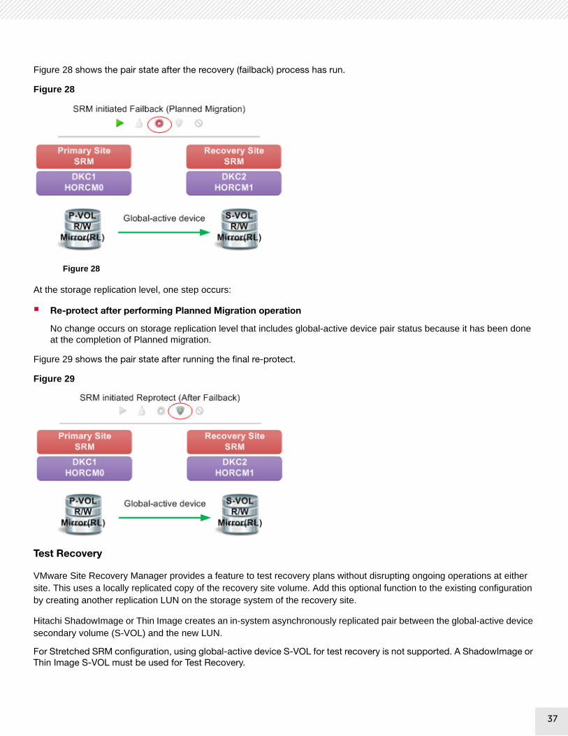
Recovery (Failback)
When ready to resume normal operations, failback is required to migrate the production workload back to the primary site.
Essentially, the failback process works the same as another recovery operation, except it works in the reverse direction of the initial recovery process.
At the storage replication level, three steps occur:
Planned migration ? Enable vMotion of eligible VMs
Recovery process initiates a replication swap resync.
Primary site volume converts to a primary volume (P-VOL).
Recovery site volume converts to a secondary volume (S-VOL).
Global-active device replication initiates from primary site to recovery site.
36
37
Figure 28 shows the pair state after the recovery (failback) process has run.
Figure 28
Figure 28
At the storage replication level, one step occurs:
Re-protect after performing Planned Migration operation
No change occurs on storage replication level that includes global-active device pair status because it has been done at the completion of Planned migration.
Figure 29 shows the pair state after running the final re-protect.
Figure 29
Test Recovery
VMware Site Recovery Manager provides a feature to test recovery plans without disrupting ongoing operations at either site. This uses a locally replicated copy of the recovery site volume. Add this optional function to the existing configuration by creating another replication LUN on the storage system of the recovery site.
Hitachi ShadowImage or Thin Image creates an in-system asynchronously replicated pair between the global-active device secondary volume (S-VOL) and the new LUN.
For Stretched SRM configuration, using global-active device S-VOL for test recovery is not supported. A ShadowImage or Thin Image S-VOL must be used for Test Recovery.
37

38
Figure 30 provides a diagram of the relationship between the global-active device and locally replicated copy pairs.
Figure 30
The global-active device secondary volume (S-VOL) becomes the ShadowImage or Thin Image primary volume (P-VOL).
A HORCM instance (horcm2) manages the ShadowImage or Thin Image secondary volume (S-VOL).
The ShadowImage or Thin Image secondary volume (S-VOL) is read-only. The recovery site’s ESXi host cannot access it.
When initiating the test recovery process, the replicated virtual machines attach to one of the following:
A non-production vSphere virtual switch
A private network specified in the recovery plan to avoid network conflicts with the protected virtual machines running on the primary site
At the storage replication level, two steps occur:
Test recovery process initiates a replication split of the ShadowImage or Thin Image pair.
The Recovery site ShadowImage or Thin Image replicated volume (S-VOL) is made read/write.
Figure 31 shows the pair state after the test recovery process has run.
Figure 31
38

39
This configuration allows the ESXi host at the recovery site to power on the replicated virtual machines safely without dis-rupting the global-active device replication. This provides the administrator with a tangible method for testing and validating the disaster recovery process.
Note — Set the following parameter value according to your environment when performing test recovery.- [$SplitReplication]- [$RMSRATMU] “$SplitReplication” is used only when performing the test recovery with Universal Replicator S-VOL or TrueCopy S-VOL in Non-stretched storage configuration. $SplitReplication=true is not supported for global-active device pairs.
Cleanup
After running a test recovery operation, the cleanup process returns the recovery site ESXi host to its original state. This powers off and deletes the replicated virtual machines.
At the storage replication level, two steps occur:
On the recovery site, the ShadowImage or Thin Image replicated volume (S-VOL) becomes read-only.
The cleanup process resumes ShadowImage or Thin Image replication.
Figure 32 shows the pair state after the cleanup process has run.
Figure 32
Test Results
This section describes the results of each test case.
VMware Site Recovery Manager feature test cases
VMware vSphere feature test cases
Failure test cases requiring Failover operation performed by VMware Site Recovery Manager
[Failback] Recovering from Disaster Recovery or Planned Migration performed by VMware Site Recovery Manager
A portion of a failure test case is not listed if it does not require any failover operation performed by VMware Site Recovery Manager such as a single path failure, recovery site failure, etc.
39

40
Table 8 shows the results of VMware Site Recovery Manager feature test cases. All test results were successful.
TABLE 8. THE RESULTS OF VMWARE SITE RECOVERY MANAGER FEATURE TEST CASES
# Scenario Global-active device /Hitachi Dynamic Link
Manager Behavior
Observed VMware Behavior
VMware Site Recovery Manager Feature Test Cases
1
Test Recovery using ShadowImage S-VOL
No impact
(This uses a locally replicated copy of the recovery site volume.)
No impact
When performing <Test> operation from SRM in the primary site;
Test recovery was conducted in a closed environment on the recovery site with an another VM generated from the volume replicated by ShadowImage.
When performing <Cleanup> operation form SRM in the primary site;
Cleanup for test recovery using ShadowImage pair resync was successful with no impact to the protection group protected by global-active device.
2
Planned Migration using Cross vCenter Server vMotion with Stretched Storage
The role of volume and replication direction of a global-active device pair was switched over when performing <Recovery - Planned migration [Enable vMotion of eligible VMs]> operation from SRM on the primary site.
The P-VOL converts to the S-VOL.
The S-VOL converts to the P-VOL.
A Tenant virtual machine was migrated with no downtime using Cross-vCenter vMotion from the primary site to recovery site when performing <Recovery - Planned migration [Enable vMotion of eligible VMs]> operation from SRM on the primary site.
No disruption to virtual machines.
40

41
Table 9 shows the results of VMware vSphere feature test cases. All test results were successful.
TABLE 9. THE RESULTS OF VMWARE FEATURE TEST CASES
# Scenario Global-active device /Hitachi Dynamic Link
Manager Behavior
Observed VMware Behavior
VMware feature test cases
1 Use VMware vMotion to migrate virtual machines between ESXi hosts in Primary Site.
No impact A Tenant virtual machine migrated to another primary site ESXi host.
A Tenant virtual machine was protected continuously by SRM when vMotion was performed.
2 Use VMware High Availability to failover virtual machines between ESXi hosts in the primary site.
(Single ESXi host failure etc.)
No impact A Tenant virtual machine failed over to another primary site ESXi host.
A Tenant virtual machine was protected continuously by SRM when VMware HA failover was performed.
3 All paths down occurs in single host in the cluster on Primary Site (using VMware HA advanced setting (VMCP))
(HBA failure etc.)
Global-active device: No change
HDLM: no alternate path because of all path down (APD)
The tenant VM failed over to the other primary site host automatically when VMCP detected all paths down.
The Tenant virtual machine was protected continuously by SRM.
41

42
Table 10 shows the results of Failure test cases requiring Failover with VMware Site Recovery Manager. All test results were successful.
TABLE 10. THE RESULTS OF FAILURE TEST CASES REQUIRING FAILOVER WITH VMWARE SITE RECOVERY MANAGER
# Scenario Global-active device /Hitachi Dynamic Link
Manager Behavior
Observed VMware Behavior
Failure test cases requiring Failover with Site Recovery Manager
1 Primary Site failure Global-active device verified data integrity with the quorum disk before failover.
Storage replication between global-active device (PVOL) and global-active device (S-VOL) stopped (pairsplit) and storage failover occurred.
Global-active device (S-VOL) was converted to SSWS (S Local). Please refer to Note #1
The tenant virtual machine was migrated to recovery site ESXi host when performing <Recovery - Disaster Recovery> operation from SRM on the recovery site.
A Tenant virtual machine I/O was restarted using global-active device S-VOL on the recovery site after the <Recovery - Disaster Recovery> operation.
2 Primary Storage failure Global-active device verified data integrity with the quorum disk before failover.
Global-active device split the pair replication.
Host I/O in the primary site was redirected via Dynamic Link Manager to the cross-site path (standby) to global-active device (S-VOL) on the recovery site storage system.
(Please refer to Note #1)
No impact for VMs because VM I/O in the primary site was redirected to the cross-site path to remote storage in the recovery site.
The ESXi host where tenant VM resided was not stable due to access loss to SAN boot device triggered by primary storage failure.
The management host in the primary site where vCenter and SRM etc. resided lost all paths to data including both SAN boot device and data device.
Need to consider performing a Recovery operation.
(Please refer to Note #2)
The tenant VMs were able to restart on the recovery site after a retry of the Recovery operation.
42

43
1. When replication is stopped due to failure, either P-VOL or S-VOL is converted to be available from hosts determined by several conditions such as Quorum state in order to maintain data integrity. The Local mode enables to access from the hosts and the Blocked mode is unable to access these hosts. This reference architecture lists S-Local cases, which have a high possibility of requiring that Site Fail over be conducted by Site Recovery Manager. On the other hand, P-local is not required to fail over to the recovery site because the tenant VM I/O in the primary site continues to access the P-VOL(P-Local) on the primary site storage as a normal state. 2. Perform <Recovery - Disaster Recovery> operation from SRM on the recovery site to restart VM on recovery site.
If the Recovery operation is not successful with an error related to being unable to boot VMs in the recovery site due to vmdk being locked by the primary site host, this occurs due to the following conditions:
<Conditions>
- A Tenant virtual machine I/O in the primary site is redirected to cross-site path to remote storage in the recovery site.
- Unable to communicate between vCenter/SRM server in the primary site and vCenter/SRM server in the recovery site due to an all ESXi hosts failure in the primary site, including the management server where vCenter and SRM reside.
- Unable to shut down the host where VM still resides in one site from the other site.
3. Retry <Recovery - Disaster Recovery> operation after performing the following workaround:
<Workaround>
One of the following workarounds is required.
3 Storage replication link failure Global-active device verified data integrity with the quorum disk before failover.
Global-active device split the pair replication.
Host I/O in the primary site was redirected via Dynamic Link Manager to the cross-site path (standby) to global-active device (S-VOL) paths on the recovery site storage system.
(Please refer to Note#1)
No impact
The tenant VM I/O in the primary site was redirected to the cross-site path to remote storage on recovery site.
(Please refer to Note #3)
4 Quorum failure No impact
(Please refer to Note #4)
No impact
TABLE 10. THE RESULTS OF FAILURE TEST CASES REQUIRING FAILOVER WITH VMWARE SITE RECOVERY MANAGER (CONTINUED)
43

44
1. If disaster recovery fails, disconnect cross-site paths and run disaster recovery again. 2. If disaster recovery fails, shut down VMs in the primary site and run disaster recovery again. 3. Consider performing <Recovery - Disaster Recovery> operation from a site affinity perspective if a tenant virtual machine I/O response is delayed when using a cross-site path. 4. Hitachi Virtual Storage Platform Gx00 has the enhancement of the global-active device quorum disk from SVOS 7(83-04-0X or later). Even if a global-active device quorum disk failure occurs, the P-VOL and S-VOL pair status and the I/O mode remain "PAIR (Mirror(RL))" and the tenant virtual machine I/O continues to process in the P-VOL in primary site storage.
Table 11 shows the results of [Failback] Recovery from Disaster Recovery or Planned Migration with VMware Site Recovery Manager. The test results were successful.
44

45
Failback operations should be performed after completion of recovery operations against all failures.
TABLE 11. THE RESULTS OF [FAILBACK] RECOVERY FROM DISASTER RECOVERY OR PLANNED MIGRATION WITH VMWARE SITE RECOVERY MANAGER
# Scenario Global-active device /Hitachi Dynamic Link
Manager Behavior
Observed VMware Behavior
[Failback] Recovery from Disaster Recovery or Planned Migration with VMware Site Recovery Manager
1 [Failback]
Recovery from Disaster Recovery
and
Recovery from Planned Migration
Step 1. - Perform <Reprotect> operation from SRM on the recovery site after recovery from all failures or Planned Migration.
Global-active device pair status was not changed when performing <Reprotect> operation.
No impact.
A tenant virtual machine status was not changed when performing <Reprotect> operation from SRM on the recovery site.
Step 2. - Perform <Recovery - Planned migration [Enable vMotion of eligible VMs]> operation from SRM on the primary site after Step 1.
Global-active device pair status was changed when performing <Recovery - Planned migration [Enable vMotion of eligible VMs]> operation.
The S-VOL converts to the P-VOL.
The P-VOL converts to the S-VOL.
A tenant virtual machine was migrated with no downtime using Cross-vCenter vMotion from the recovery site to primary site when performing <Recovery - Planned migration [Enable vMotion of eligible VMs]> operation from SRM on the primary site.
No disruption to virtual machines.
Step 3. - Perform <Reprotect> operation again from SRM on the primary site.
Global-active device pair status was not changed when performing <Reprotect> operation.
A tenant virtual machine status was not changed when performing <Reprotect> operation from SRM on the primary site.
45

For More InformationHitachi Data Systems Global Services offers experienced storage consultants, proven methodologies and a comprehensive services portfolio to assist you in implementing Hitachi products and solutions in your environment. For more information, see the Services website.
Live and recorded product demonstrations are available for many Hitachi products. To schedule a live demonstration, contact a sales representative. To view a recorded demonstration, see the Resources website.
Hitachi Data Systems Academy provides best-in-class training on Hitachi products, technology, solutions and certifications. Hitachi Data Systems Academy delivers on-demand web-based training (WBT), classroom-based instructor-led training (ILT) and virtual instructor-led training (vILT) courses. For more information, see the Hitachi Data Systems Services Training and Certification website.
For more information about Hitachi products and services, contact your sales representative or channel partner or visit the Hitachi Data Systems website.

1
Corporate Headquarters2845 Lafayette StreetSanta Clara, CA 95050-2639 USAwww.HDS.com community.HDS.com
Regional Contact InformationAmericas: +1 866 374 5822 or [email protected], Middle East and Africa: +44 (0) 1753 618000 or [email protected] Pacific: +852 3189 7900 or [email protected]
HITACHI is a trademark or registered trademark of Hitachi, Ltd., Microsoft, Active Directory, Hyper-V, SharePoint, SQL Server, and Windows Server are trademarks or registered trademarks of Microsoft Corporation. Other notices if required. All other trademarks, service marks and company names are properties of their respective owners.
Notice: This document is for informational purposes only, and does not set forth any warranty, expressed or implied, concerning any equipment or service offered or to be offered by Hitachi Data Systems Corporation.
AS-600-00, June 2017.