High speed detecting and identification for car charging ...
123
High speed detecting and identification for car charging on electric roads IULIANA STOICA AND VIKTOR NYBOM MASTER´S THESIS DEPARTMENT OF ELECTRICAL AND INFORMATION TECHNOLOGY | FACULTY OF ENGINEERING | LTH | LUND UNIVERSITY
Transcript of High speed detecting and identification for car charging ...

High speed detecting and identificationfor car charging on electric roads
IULIANA STOICA AND VIKTOR NYBOMMASTER´S THESISDEPARTMENT OF ELECTRICAL AND INFORMATION TECHNOLOGY |FACULTY OF ENGINEERING | LTH | LUND UNIVERSITY
Printed by Tryckeriet i E-huset, Lund 2017
IULIA
NA
STOIC
A A
ND
VIK
TOR
NY
BO
MH
igh speed detecting and identification for car charging on electric roads
LUN
D 2017
Series of Master’s thesesDepartment of Electrical and Information Technology
LU/LTH-EIT 2017-564
http://www.eit.lth.se
High speed detecting and identification for carcharging on electric roads
Iuliana Stoica And Viktor Nybom
Division of Industrial Electrical Engineering and AutomationFaculty of Engineering (IEA), Lund University
Department of Electrical and Information Technology (EIT)Lund University
Supervisors:Lars Lindgren (IEA)
Fredrik Tufvesson (EIT)
Examiners:Mats Alaküla (IEA)
Mats Gustafsson (EIT)
March 2, 2017

c© 2017Printed in SwedenTryckeriet i E-huset, Lund
Abstract
The constantly increasing awareness of protecting the environment has put electri-cal roads in the spotlight as an alternative solution to fossil driven means of trans-port. Dan Zethraeus has developed an innovative idea for a prototype electricalroad which conductively supplies power to the cars whilst driving. The concept isto place a line of short rail segments in the middle of the drive lanes where eachrail can have either grounded or positive polarity. The aim of this thesis work isto find solutions for the timing, detection and identification of cars so that thepositive conductive rails are switched on correctly. The possible electromagneticinterference from the road is to be investigated and the communication methodsadjusted accordingly. Finally, a demonstrator is built as a proof of concept forillustrating and testing the presented solution.
This report starts by presenting possible theoretical solutions for the detection andidentification. Experiments that are set up to further analyse the most promisingmethods, and also the construction of the electronics for the detection and iden-tification modules of the demonstrator follow. Furthermore, a simulation setupfor analysis of the electromagnetic interference is tested. The complete solutionand the whole setup of the demonstrator is presented in the last part. Resultsare presented for the performance of the demonstrator when tested on a real cardriving at 30 km/h.
i

Terminology
EMI - electromagnetic interferenceRFID - radio frequency identificationRSU - radio station unitTSS - Traffic Supervisions Systems
ii
Contents
1 Introduction 11.1 Background . . . . . . . . . . . . . . . . . . . . . . . . . . . . . . . 11.2 Related work . . . . . . . . . . . . . . . . . . . . . . . . . . . . . . 11.3 Aim of this thesis work . . . . . . . . . . . . . . . . . . . . . . . . . 31.4 Limitations . . . . . . . . . . . . . . . . . . . . . . . . . . . . . . . 3
2 Approach 52.1 Approach and dividing the problem . . . . . . . . . . . . . . . . . . 52.2 Finding information . . . . . . . . . . . . . . . . . . . . . . . . . . . 5
3 Theoretical solutions 73.1 Solutions for car identification . . . . . . . . . . . . . . . . . . . . . 7
3.1.1 RFID technology . . . . . . . . . . . . . . . . . . . . . . . . . 83.2 Solutions for car positioning . . . . . . . . . . . . . . . . . . . . . . 13
3.2.1 Identifying antenna signal strength . . . . . . . . . . . . . . . . . 143.2.2 Doppler effect . . . . . . . . . . . . . . . . . . . . . . . . . . 143.2.3 Inductive detection . . . . . . . . . . . . . . . . . . . . . . . . 163.2.4 Conductive pickup signaling . . . . . . . . . . . . . . . . . . . . 193.2.5 Short circuit detectors on rail . . . . . . . . . . . . . . . . . . . 203.2.6 Hall effect sensors . . . . . . . . . . . . . . . . . . . . . . . . 213.2.7 Sound and vibration . . . . . . . . . . . . . . . . . . . . . . . 21
3.3 Different communication schemes . . . . . . . . . . . . . . . . . . . 223.3.1 Scenario one . . . . . . . . . . . . . . . . . . . . . . . . . . . 223.3.2 Scenario two . . . . . . . . . . . . . . . . . . . . . . . . . . . 233.3.3 Scenario three . . . . . . . . . . . . . . . . . . . . . . . . . . 23
4 Analysis and testing 254.1 Car positioning . . . . . . . . . . . . . . . . . . . . . . . . . . . . . 25
4.1.1 Pendulum as experimental setup . . . . . . . . . . . . . . . . . . 254.1.2 Inductive system from the previous thesis work . . . . . . . . . . . 264.1.3 Experimenting with different near field antennas . . . . . . . . . . . 294.1.4 Simulating, testing and building . . . . . . . . . . . . . . . . . . 314.1.5 Testing the detection on a road with a car . . . . . . . . . . . . . 39
4.2 Car identification . . . . . . . . . . . . . . . . . . . . . . . . . . . . 42
iii
4.3 EMI . . . . . . . . . . . . . . . . . . . . . . . . . . . . . . . . . . . 434.3.1 EMI from electric car . . . . . . . . . . . . . . . . . . . . . . . 47
4.4 The Complete system . . . . . . . . . . . . . . . . . . . . . . . . . 474.4.1 Building . . . . . . . . . . . . . . . . . . . . . . . . . . . . . 484.4.2 Programming . . . . . . . . . . . . . . . . . . . . . . . . . . 494.4.3 Final test . . . . . . . . . . . . . . . . . . . . . . . . . . . . 504.4.4 Result . . . . . . . . . . . . . . . . . . . . . . . . . . . . . . 51
5 Discussion and future work 57
A Program Code 59A.1 Receiver Arduino Due: The rail road computer . . . . . . . . . . . . 59A.2 RSU . . . . . . . . . . . . . . . . . . . . . . . . . . . . . . . . . . . 81
A.2.1 StartServerUDP.java . . . . . . . . . . . . . . . . . . . . . . . 81A.2.2 Monitor.java . . . . . . . . . . . . . . . . . . . . . . . . . . . 84A.2.3 RoadConnectionUDP.java . . . . . . . . . . . . . . . . . . . . . 86A.2.4 CarServerThread.java . . . . . . . . . . . . . . . . . . . . . . . 93A.2.5 RecThread.java . . . . . . . . . . . . . . . . . . . . . . . . . . 93A.2.6 RSU2Road.java . . . . . . . . . . . . . . . . . . . . . . . . . . 97
A.3 Car code . . . . . . . . . . . . . . . . . . . . . . . . . . . . . . . . 98A.3.1 serial.c . . . . . . . . . . . . . . . . . . . . . . . . . . . . . . 98A.3.2 testSync.cc . . . . . . . . . . . . . . . . . . . . . . . . . . . . 100A.3.3 monitor.h . . . . . . . . . . . . . . . . . . . . . . . . . . . . 104A.3.4 monitor.cc . . . . . . . . . . . . . . . . . . . . . . . . . . . . 104A.3.5 connection.h . . . . . . . . . . . . . . . . . . . . . . . . . . . 106A.3.6 connection.cc . . . . . . . . . . . . . . . . . . . . . . . . . . 108
iv
Chapter1Introduction
1.1 Background
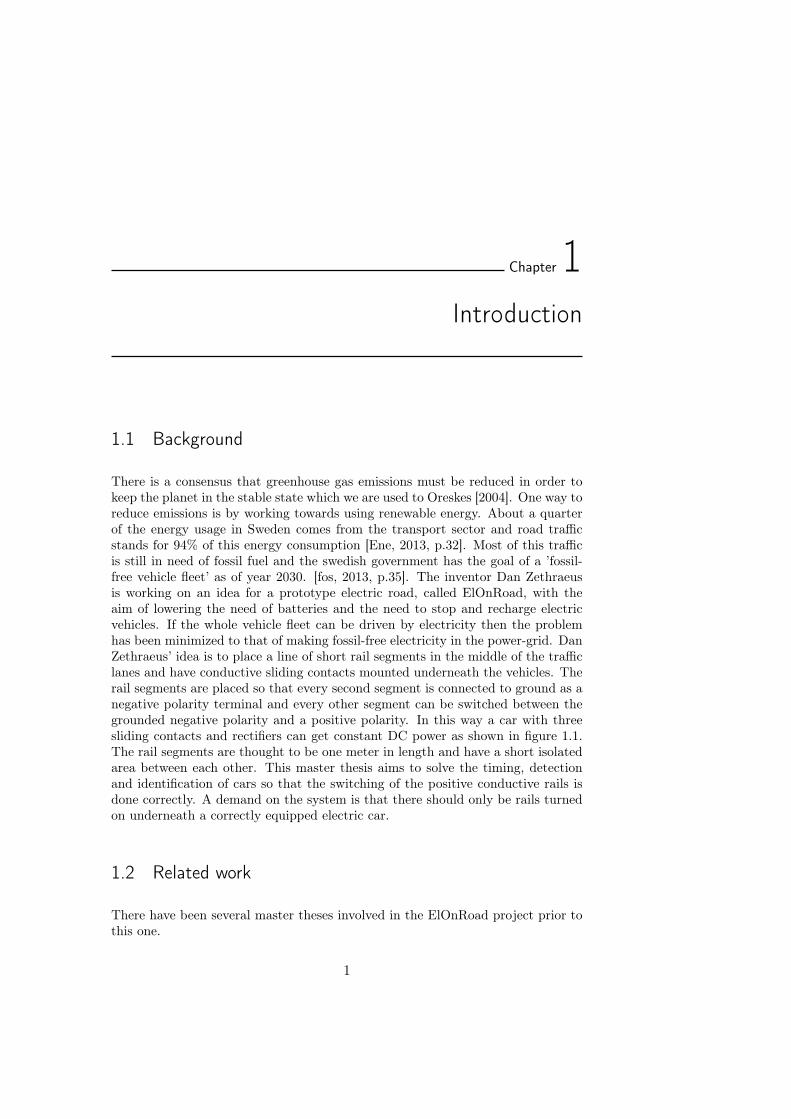
There is a consensus that greenhouse gas emissions must be reduced in order tokeep the planet in the stable state which we are used to Oreskes [2004]. One way toreduce emissions is by working towards using renewable energy. About a quarterof the energy usage in Sweden comes from the transport sector and road trafficstands for 94% of this energy consumption [Ene, 2013, p.32]. Most of this trafficis still in need of fossil fuel and the swedish government has the goal of a ’fossil-free vehicle fleet’ as of year 2030. [fos, 2013, p.35]. The inventor Dan Zethraeusis working on an idea for a prototype electric road, called ElOnRoad, with theaim of lowering the need of batteries and the need to stop and recharge electricvehicles. If the whole vehicle fleet can be driven by electricity then the problemhas been minimized to that of making fossil-free electricity in the power-grid. DanZethraeus’ idea is to place a line of short rail segments in the middle of the trafficlanes and have conductive sliding contacts mounted underneath the vehicles. Therail segments are placed so that every second segment is connected to ground as anegative polarity terminal and every other segment can be switched between thegrounded negative polarity and a positive polarity. In this way a car with threesliding contacts and rectifiers can get constant DC power as shown in figure 1.1.The rail segments are thought to be one meter in length and have a short isolatedarea between each other. This master thesis aims to solve the timing, detectionand identification of cars so that the switching of the positive conductive rails isdone correctly. A demand on the system is that there should only be rails turnedon underneath a correctly equipped electric car.
1.2 Related work
There have been several master theses involved in the ElOnRoad project prior tothis one.
1
2 Introduction
Figure 1.1: Electric road giving constant DC power to a car withthree sliding contacts passing over it.
Philip Abrahamsson Completed his master thesis [Abrahamsson, 2015] on afirst overall design. Part of the focus was on simulating the magnetic prop-erties and design of over-voltage protection using LT-spice, Matlab andFEMM. Abrahamsson also did simulations on lightning strikes hitting theroad and what effects this would give. Abrahamsson’s results on magneticproperties have been background knowledge in our work, although the ge-ometry doesn’t fully align.
Marcus Andersson Completed his master thesis [Andersson, 2014] with focuson the switching circuit in the rails. Andersson was also part of buildingand fitting all the electronics in a full-scale proof of concept.
Henrik Fritzon Sund Completed his master thesis [Sund, 2014] with focus ondetecting a vehicle and creating a control system for activating the switchingof an individual rail. Sund’s work has been of great help to us and a greatpart of our master thesis is a further development of his work and thoughts.
Filip Lillevars had not fully completed his master thesis before we wrote oursbut given support in first hand on our work.
Emil Landqvist & Theodor Hallerby Completed their master thesis [Landqvistand Hallerby, 2015] with focus on developing a more comprehensive modelof the road. The main focus has been on the thermal aspects and analysingoverheating in different environments.
There are a couple of other electric road projects emerging in Sweden. The twobiggest are shortly mentioned here.
Elways [elw, 2015] Is a system that allows both heavy and light electric vehiclesto charge while driving. The system consist of a rail in the road, with slidingslots. An arm on the vehicle can grab on to the rail and have a conductivetransmission of power.

Introduction 3
eHighway [sie, 2016] Is a system that lets trucks and high vehicles to chargewhile driving. In this system there are power lines hanging over the roadand the trucks have pickups mounted on the roof. Quite similar to a theelectric train network.
Other work found to be related to this master thesis is the use of RFID in trainsystems and car positioning described in section 3.2.1.
1.3 Aim of this thesis work
The aim of this thesis work is:
1. To come up with a theoretic solution to uniquely identify a correctly equippedcar, traveling at speeds between 20 km/h and 200 km/h and to determinewhen to activate and deactivate the positive one meter rail segments in theelectrical road ElOnRoad. This should have enough accuracy so that a railis only active when it absolutely needs to be and no high potential partspoint out from under the passing car.
2. To identify and determine the possible electromagnetic interference from theroad and compensate the communication for this.
3. To build a demonstrator as proof of concept capable of identifying, position-ing and correctly activating something at a speed of around 50 km/h.
1.4 Limitations
Some parts of the combined and full solution as well as some minor parts ofour work have been left out since it could hinder Dan Zethraeus from protectingsensitive parts of his invention.
Identification methods using cameras or lasers are not considered in this reportsince the environment around a road can get wet and dirty and componentsmounted on a car are subject to high tear.
This master thesis aims at designing a proof of concept turning on LED lightsinstead of a power giving rail. This thesis does not aim at finding or usingcomponents or optimizing code for use in a real prototype with demands onheat and durability.
It is in this report expected to be sufficient length between the ends of the carand the sliding pickup contacts relative to the length of a rail to make sureit is possible to have no active parts peek out from under the car.
In between standstill and 10 km/h are considered special conditions and will notbe the focus of this thesis work.

4 Introduction
Chapter2Approach
2.1 Approach and dividing the problem
The aim of this master thesis is to both identify a specific car and to accuratelydetermine a defined position of the car in order to switch the rail on and off withthe correct timing. As a first approach, the idea of using RFID (radio frequencyidentification) and the inductive detection circuit built by Fritzon were furtherexamined, [Sund, 2014, p.5-17]. After gaining some understanding of how RFIDsystems work (see section 3.1.1), it was decided to handle the theoretical solutionfor the identification and precise positioning separately. Different possible waysto determine the position of the car are presented in section 3.2. After this ananalysis of possible ways to combine the solutions with RFID are discussed insection 3.3. The chosen solution is then tested and analyzed in chapter 4 wherefinally a complete test of the proof of concept is carried out and described insection 4.4.
2.2 Finding information
A lot of knowledge and know-how from courses attended at LTH have been of use tous working with this thesis project. Most of the knowledge and information aboutradio transmission and RFID are gathered from the RFID Handbook [Finkenzeller,2010] and from various research articles found on the Internet. Our supervisorLars Lindgren has been a great help to most of our other needs of finding andgaining information and knowledge about everything from EMI (electromagneticinterference) to design and measurements.
5

6 Approach
Chapter3Theoretical solutions
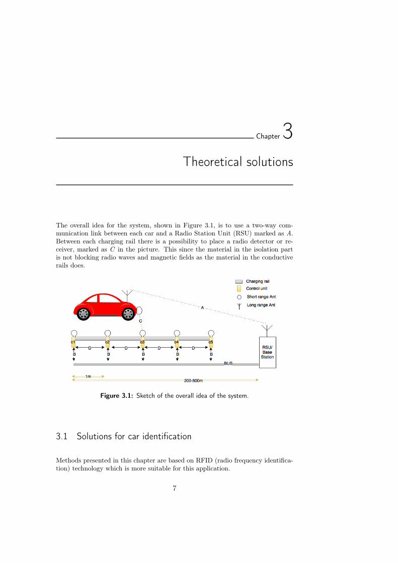
The overall idea for the system, shown in Figure 3.1, is to use a two-way com-munication link between each car and a Radio Station Unit (RSU) marked as A.Between each charging rail there is a possibility to place a radio detector or re-ceiver, marked as C in the picture. This since the material in the isolation partis not blocking radio waves and magnetic fields as the material in the conductiverails does.
Figure 3.1: Sketch of the overall idea of the system.
3.1 Solutions for car identification
Methods presented in this chapter are based on RFID (radio frequency identifica-tion) technology which is more suitable for this application.
7
8 Theoretical solutions
3.1.1 RFID technology
A RFID system consists of two main parts, the interrogator, or the reader, andthe transponder which is located on the object to be identified [Finkenzeller, 2010,p. 6]. The reader generates a radio signal and when a transponder is locatedwithin the reader’s range and can pick up the signal it gets activated and startsdata exchange. The transponder consists of a coupling element and a microchipwhere data is stored and modulation is done. A transponder can be passive if itgets power supplied by the field generated by the reader or active if it has its ownpower source.
Communicating data can be done in full-, half-duplex or sequential mode. In full-duplex mode both sides are sending and receiving data simultaneously, whereas inhalf-duplex and sequential mode reader and transponder are taking turns on send-ing data. Transfer of energy from reader to transponder is continuous in duplexmode but it occurs only in between the messages in sequential mode [Finkenzeller,2010, p. 39]. All digital modulation techniques can be used to transmit data butamplitude shift keying is the one most commonly used. There are a few couplingmethods,i.e ways of energy transfer between reader and transponder. Based onreasonable distance ranges for this applications and availability of products on themarket this report will only review inductive and backscatter coupling [Finken-zeller, 2010, p. 22, 45].
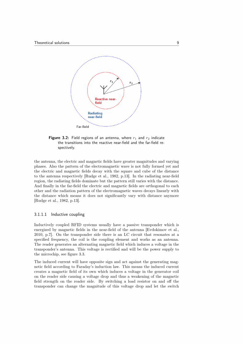
A quick review of radio waves and the different kind of fields that can be foundaround an antenna is given for a better understanding of the coupling methods.The regions surrounding an antenna are usually divided into three zones: reactivenear-field, radiating near-field (Fresnel) and far-field (Fraunhofer) [Balanis, 2005,p. 34]. The transition boundaries between these regions are gradual but thereare general approximations that work for most antennas. The transition fromreactive near field to radiating near field and far field is usually approximated bythe transition distances r1 and r2 [Balanis, 2005, p. 34]:
r1 = 0.62 ·√D3/λ
r2 = 2D2/λ,
where D is the largest dimension of the antenna and λ is the wavelength, see figure3.2. Note that D must be much larger than the wavelength for these boundariesto be valid. For very short dipole antennas, where the largest dimension of theantenna is less than the wavelength, the transition out of the reactive near-field isaccording to Balanis often approximated by:
r1 = λ/2π, (3.1)
Radio waves are electromagnetic radiation created by accelerating charges. Thismovement of charges generates electric and magnetic fields which together formelectromagnetic fields. In the reactive near-field, which is the region closest to
Theoretical solutions 9
Figure 3.2: Field regions of an antenna, where r1 and r2 indicatethe transitions into the reactive near-field and the far-field re-spectively.
the antenna, the electric and magnetic fields have greater magnitudes and varyingphases. Also the pattern of the electromagnetic wave is not fully formed yet andthe electric and magnetic fields decay with the square and cube of the distanceto the antenna respectively [Rudge et al., 1982, p.13]. In the radiating near-fieldregion, the radiating fields dominate but the pattern still varies with the distance.And finally in the far-field the electric and magnetic fields are orthogonal to eachother and the radiation pattern of the electromagnetic waves decays linearly withthe distance which means it does not significantly vary with distance anymore[Rudge et al., 1982, p.13].
3.1.1.1 Inductive coupling
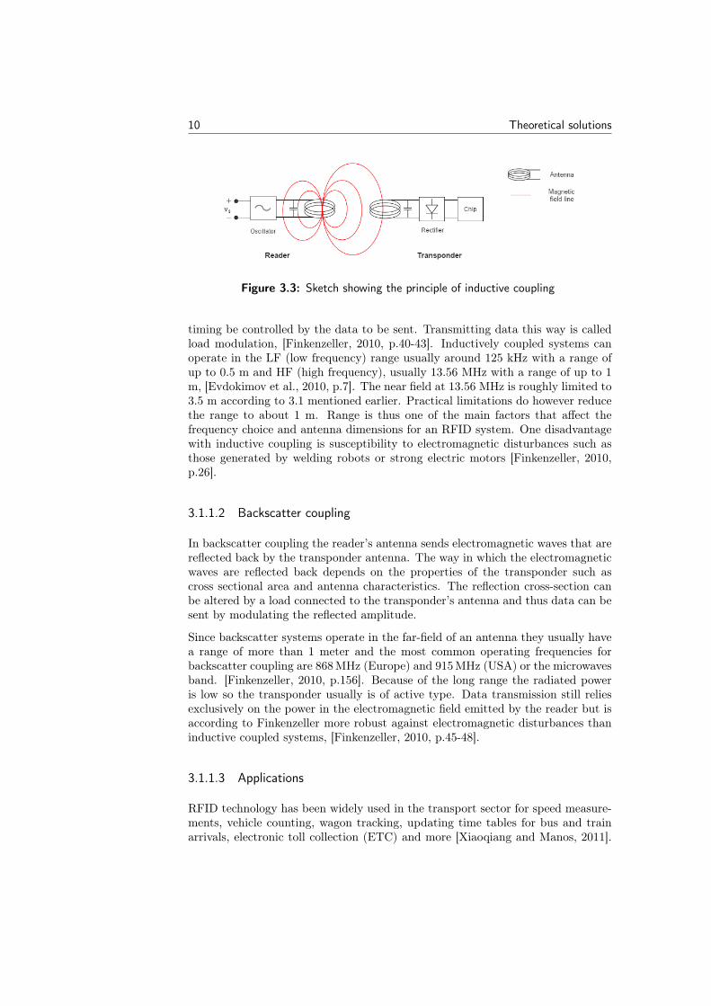
Inductively coupled RFID systems usually have a passive transponder which isenergized by magnetic fields in the near-field of the antenna [Evdokimov et al.,2010, p.7]. On the transponder side there is an LC circuit that resonates at aspecified frequency, the coil is the coupling element and works as an antenna.The reader generates an alternating magnetic field which induces a voltage in thetransponder’s antenna. This voltage is rectified and will be the power supply tothe microchip, see figure 3.3.
The induced current will have opposite sign and act against the generating mag-netic field according to Faraday’s induction law. This means the induced currentcreates a magnetic field of its own which induces a voltage in the generator coilon the reader side causing a voltage drop and thus a weakening of the magneticfield strength on the reader side. By switching a load resistor on and off thetransponder can change the magnitude of this voltage drop and let the switch
10 Theoretical solutions
Figure 3.3: Sketch showing the principle of inductive coupling
timing be controlled by the data to be sent. Transmitting data this way is calledload modulation, [Finkenzeller, 2010, p.40-43]. Inductively coupled systems canoperate in the LF (low frequency) range usually around 125 kHz with a range ofup to 0.5 m and HF (high frequency), usually 13.56 MHz with a range of up to 1m, [Evdokimov et al., 2010, p.7]. The near field at 13.56 MHz is roughly limited to3.5 m according to 3.1 mentioned earlier. Practical limitations do however reducethe range to about 1 m. Range is thus one of the main factors that affect thefrequency choice and antenna dimensions for an RFID system. One disadvantagewith inductive coupling is susceptibility to electromagnetic disturbances such asthose generated by welding robots or strong electric motors [Finkenzeller, 2010,p.26].
3.1.1.2 Backscatter coupling
In backscatter coupling the reader’s antenna sends electromagnetic waves that arereflected back by the transponder antenna. The way in which the electromagneticwaves are reflected back depends on the properties of the transponder such ascross sectional area and antenna characteristics. The reflection cross-section canbe altered by a load connected to the transponder’s antenna and thus data can besent by modulating the reflected amplitude.
Since backscatter systems operate in the far-field of an antenna they usually havea range of more than 1 meter and the most common operating frequencies forbackscatter coupling are 868 MHz (Europe) and 915 MHz (USA) or the microwavesband. [Finkenzeller, 2010, p.156]. Because of the long range the radiated poweris low so the transponder usually is of active type. Data transmission still reliesexclusively on the power in the electromagnetic field emitted by the reader but isaccording to Finkenzeller more robust against electromagnetic disturbances thaninductive coupled systems, [Finkenzeller, 2010, p.45-48].
3.1.1.3 Applications
RFID technology has been widely used in the transport sector for speed measure-ments, vehicle counting, wagon tracking, updating time tables for bus and trainarrivals, electronic toll collection (ETC) and more [Xiaoqiang and Manos, 2011].
Theoretical solutions 11
This section will present a few examples of relevant high-speed RFID applicationsand experiments.
LF spectrum
Most of the RFID applications in the LF (low frequency) spectrum have an op-erating frequency of 125 kHz. TSS (Traffic Supervisions Systems) is a companywhich has developed solutions for several ITS (Intelligent Transportation System)applications for roads and railways. Their systems can be structured into twocategories: AVI (Automatic Vehicle Identification) and AVL (Automatic VehicleLocation). In AVI systems the tags are placed on the vehicle and readers in theinfrastructure. In AVL systems the reader is mounted on the vehicle and tags areplaced at specific positions in roads/railways, each tag corresponding to a locationregistered in a database. The read tag ID can for example be sent to a centralinformation system via radio or just used by the car processing unit for differentpurposes.
One of the company’s AVL systems, called TPL (train position locator), has inter-esting specifications. It has a speed range of 0-300 km/h with a position accuracyof ± 1 cm at low speeds and ± 50 cm at the maximum speed, [TSS, 2015]. Theantenna dimensions are 108x335x59 mm and the tag housing has a diameter of40 mm and a length of 330 mm. The EMI environment under a train should havesimilarities to the one under a car getting power supplied conductively driving onan electrical road. The specifications of this system makes it very interesting forthe project.
HF spectrum
RFID systems with an operating frequency of 13.56 MHz are said to be workingin the HF (high frequency) spectrum. Optys Corporation, an RFID design anddeveloping company has done high-speed reading tests with a 19.5 cm long tagand 30x10 cm antenna at an operating frequency of 13.56 MHz. The tag wasattached on top of a H0 scale model train and the antenna was suspended abovethe rails. When moving at the speed of 113 km/h the tag was successfully readonce. Unfortunately a documentation report could not be found but a video of theexperiment can be watched at [Optys Corporation, 2011]. The distance betweenthe reader and the tag is not specified but judging from the video it may beroughly 10-15 cm. The standard used in this system is ISO 15693 which includesbasic communication protocols and anticollision algorithms which allow tags totake turns in communicating with the reader.
UHF spectrum
The standard called EPC Global Gen2 specifies RFID systems with a range of 2.5cm - 10 m and operating frequencies in the UHF (ultra high frequency) spectrum
12 Theoretical solutions
(858 - 930 MHz). Each RFID tag, active or passive, contains an universal identifierin the form of an EPC code (electronic product code) saved on the memory chip.
This protocol is built to suit inventories in warehouses where many products haveto be identified fast and information such as shelf life, shipping date have to beread/written to a tag. Therefore the reader has to go through these three states:select (where a population of tags are selected for inventory), inventory (whereeach tag is identified by its EPC) and access (where the reader can read/writeto the tag’s memory chip). The tag goes through the following states for com-munication: ready (waiting to be selected for an inventory), arbitrate (has beenselected but waits for its turn to identify itself), reply(identifies itself), acknowl-edged (identification succeeded), open and secured (access to the tag’s memory),[epc, 2008, p.45-48].
Harting Technology Group (HTG) has done high-speed tests using their SL89RFID tag, RF-R500-p-EU reader and WR80-30 antenna. The antenna’s operatingfrequency is specified to 902-928 MHz and the tag uses the standard EPC Gen2.The tag was mounted on the car facing the side of the road where the readerwas placed at a distance of 2.5 m at the passing point. When driving past theantenna at 200 km/h HTG got 9 correct readings of the 96 bit EPC identifier.Using their smaller Ha-VIS RF-ANT-WR30-EU antenna and Ha-VIS RF-R500-c-EU reader HTG still got 1 correct reading at 200km/h. Further specificationsof the experiment and a video can be found at [Wermke et al., 2014a], [Wermkeet al., 2014b].
Another highly interesting application is ATIS (Automatic Train IdentificationSystem) which is primarily used in identifying cargo trains usually traveling atspeeds less than 100 km/h, [Xiaoqiang and Manos, 2011]. This system has been inuse in China since 2007. A UHF reader is placed between the rails and a passivetag is mounted on the train and its reading distance is specified to about 1.4 m.Since it would be unnecessary for the reader to constantly be turned on, magneticsteel detection systems are placed at distances of 40-50 m from the reader to sendturn-on and turn-off signals to the reader when trains are approaching or leavingthe area. When a train is approaching, the reader gets turned on and the read tagID is sent further to a central information system which can update time tablesfor example. The reader is then turned off when the train has activated the othermagnetic steel detection system. The system also includes a module which canwrite information to tags.
It seems like there is a large focus on research regarding the adjusting of sucha system to modern high-speed and ultra high-speed trains which can reach avelocity of up to 500 km/h. The biggest challenges are the tag latency and thefact that the tag is within the reading range for a very short period of time forvery high speeds, [Xiaoqiang and Manos, 2011].
Theoretical solutions 13
Choosing frequency and protocol
The reading distance needed between reader and transponder will decide the ap-propriate coupling method to be used. Power losses in the environment in whichthe system is meant to be used, the regulations for the allowable radiated powerspecified for each frequency range and limitations on antenna sizes give furtherconstraints.
As mentioned before the power of the magnetic field decays with the cube of thedistance in the near-field which corresponds to 60 dB/decade. Thereafter thepower of the electromagnetic field decays linearly with distance in the far-fieldwhich corresponds to 20 dB/decade. The specifications for the maximum allowedtransmit power is usually given as the field strength at a distance of 10 m fromthe reader. Lower frequencies have a larger near-field region according to equation3.1 which means a higher initial transmit power will decay to the same strengthat 10 m as a lower initial power transmitted at a higher frequency, [Finkenzeller,2010, p.162] This is an interesting optimization aspect when choosing to work withinductively coupled systems. A lower frequency means a slower reading speedthough since there are fewer wave periods per unit of time to process. The readingrange could instead be increased by using larger tags, and thereby get a longertime window and more time for the reading to take place.
The environment of an RFID system can cause problems. Metallic surroundingscan affect the strength of the field between reader and transponder and thus reducethe reading area. This is due to eddy currents induced in the metal which opposethe initial field according to Lenz’s law. There are many solutions to this problem,one of them being ferrite shielding where a piece of ferrite with high magneticpermeability is placed between the antenna and the metal. This will prevent eddycurrents but the field strength may get higher so adjustments have to be made,[Finkenzeller, 2010, p.107-108].
An issue with using UHF RFID is that the operating frequency allowed varies andthere exists one standard in the US and one standard in EU. To maximize theefficiency of the antennas of the reader these are often tuned to either the EUstandard or the US standard and not both. So to use the UHF system in thewhole world both antenna standards would need to be installed.
In an application such as identifying objects moving at high speeds a simple pro-tocol would be the best suited. The extra functionality that EPC gen2 has is notneeded in this case and would contribute to longer read latency, mostly becauseof the anti collision algorithms.
3.2 Solutions for car positioning
In this section the different methods that were considered for the the positioningare described. Since no electric active parts are allowed to be exposed in front orback of the car the positioning needs to be accurate to within centimeters, even at
14 Theoretical solutions
higher speeds. As the environment can get dirty and the electrical road is subjectto wear and tear some methods as for example methods using photodetectors arenot suitable for this system and will not be further discussed in this report.
3.2.1 Identifying antenna signal strength
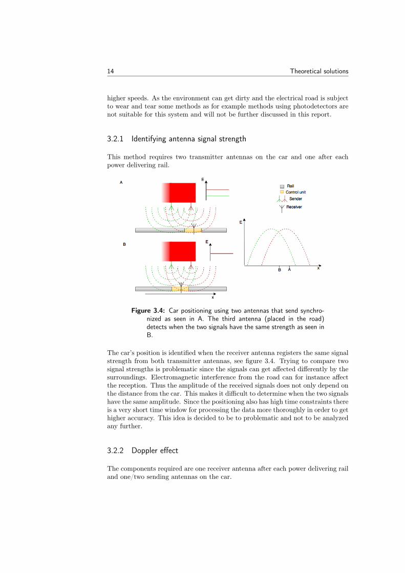
This method requires two transmitter antennas on the car and one after eachpower delivering rail.
Figure 3.4: Car positioning using two antennas that send synchro-nized as seen in A. The third antenna (placed in the road)detects when the two signals have the same strength as seen inB.
The car’s position is identified when the receiver antenna registers the same signalstrength from both transmitter antennas, see figure 3.4. Trying to compare twosignal strengths is problematic since the signals can get affected differently by thesurroundings. Electromagnetic interference from the road can for instance affectthe reception. Thus the amplitude of the received signals does not only depend onthe distance from the car. This makes it difficult to determine when the two signalshave the same amplitude. Since the positioning also has high time constraints thereis a very short time window for processing the data more thoroughly in order to gethigher accuracy. This idea is decided to be to problematic and not to be analyzedany further.
3.2.2 Doppler effect
The components required are one receiver antenna after each power delivering railand one/two sending antennas on the car.
Theoretical solutions 15
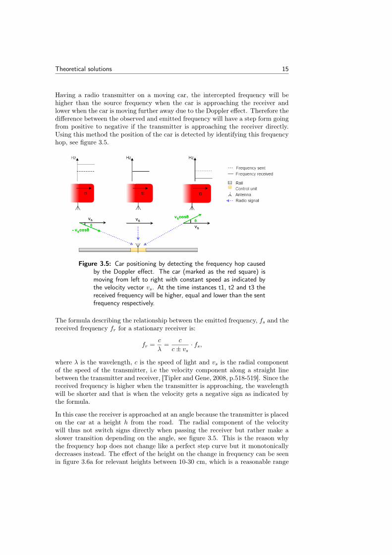
Having a radio transmitter on a moving car, the intercepted frequency will behigher than the source frequency when the car is approaching the receiver andlower when the car is moving further away due to the Doppler effect. Therefore thedifference between the observed and emitted frequency will have a step form goingfrom positive to negative if the transmitter is approaching the receiver directly.Using this method the position of the car is detected by identifying this frequencyhop, see figure 3.5.
Figure 3.5: Car positioning by detecting the frequency hop causedby the Doppler effect. The car (marked as the red square) ismoving from left to right with constant speed as indicated bythe velocity vector vs. At the time instances t1, t2 and t3 thereceived frequency will be higher, equal and lower than the sentfrequency respectively.
The formula describing the relationship between the emitted frequency, fs and thereceived frequency fr for a stationary receiver is:
fr =c
λ=
c
c± vs· fs,
where λ is the wavelength, c is the speed of light and vs is the radial componentof the speed of the transmitter, i.e the velocity component along a straight linebetween the transmitter and receiver, [Tipler and Gene, 2008, p.518-519]. Since thereceived frequency is higher when the transmitter is approaching, the wavelengthwill be shorter and that is when the velocity gets a negative sign as indicated bythe formula.
In this case the receiver is approached at an angle because the transmitter is placedon the car at a height h from the road. The radial component of the velocitywill thus not switch signs directly when passing the receiver but rather make aslower transition depending on the angle, see figure 3.5. This is the reason whythe frequency hop does not change like a perfect step curve but it monotonicallydecreases instead. The effect of the height on the change in frequency can be seenin figure 3.6a for relevant heights between 10-30 cm, which is a reasonable range
16 Theoretical solutions
(a) (b)
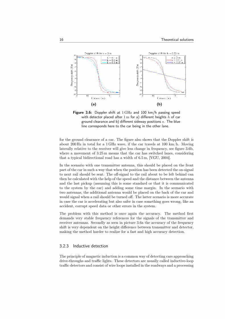
Figure 3.6: Doppler shift at 1 GHz and 100 km/h passing speedwith detector placed after 1 m for a) different heights h of carground clearance and b) different sideway positions s. The blueline corresponds here to the car being in the other lane.
for the ground clearance of a car. The figure also shows that the Doppler shift isabout 200 Hz in total for a 1 GHz wave, if the car travels at 100 km/h. Movinglaterally relative to the receiver will give less change in frequency, see figure 3.6b,where a movement of 3.25 m means that the car has switched lanes, consideringthat a typical bidirectional road has a width of 6.5 m, [VGU, 2004].
In the scenario with one transmitter antenna, this should be placed on the frontpart of the car in such a way that when the position has been detected the on-signalto next rail should be sent. The off-signal to the rail about to be left behind canthen be calculated with the help of the speed and the distance between the antennaand the last pickup (assuming this is some standard or that it is communicatedto the system by the car) and adding some time margin. In the scenario withtwo antennas, the additional antenna would be placed on the back of the car andwould signal when a rail should be turned off. The latter scenario is more accuratein case the car is accelerating but also safer in case something goes wrong, like anaccident, corrupt speed data or other errors in the system.
The problem with this method is once again the accuracy. The method firstdemands very stable frequency references for the signals of the transmitter andreceiver antennas. Secondly as seen in picture 3.6a the accuracy of the frequencyshift is very dependent on the height difference between transmitter and detector,making the method harder to realize for a fast and high accuracy detection.
3.2.3 Inductive detection
The principle of magnetic induction is a common way of detecting cars approachingdrive-throughs and traffic lights. These detectors are usually called inductive-looptraffic detectors and consist of wire loops installed in the roadways and a processing
Theoretical solutions 17
unit. The loop is oscillating with a certain frequency which increases as a car passesover it because the large amount of metal on the car lowers the inductance of theloop. Changes in frequency are processed and give the detection signal.
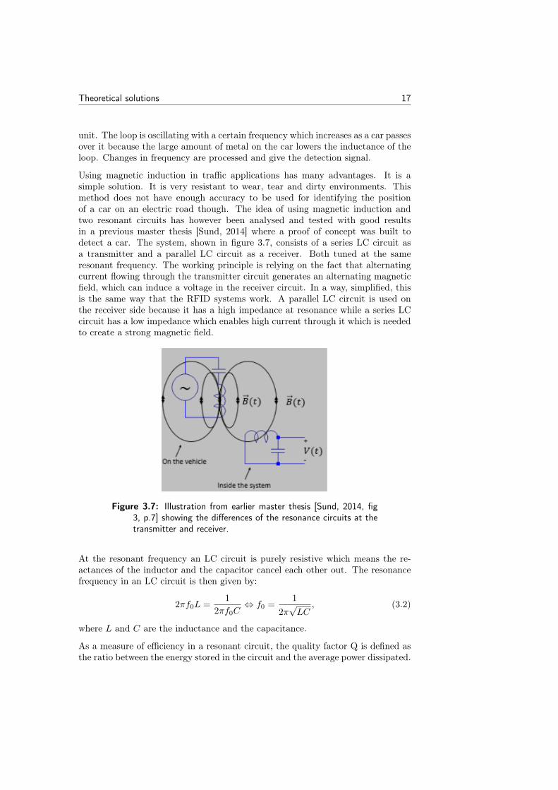
Using magnetic induction in traffic applications has many advantages. It is asimple solution. It is very resistant to wear, tear and dirty environments. Thismethod does not have enough accuracy to be used for identifying the positionof a car on an electric road though. The idea of using magnetic induction andtwo resonant circuits has however been analysed and tested with good resultsin a previous master thesis [Sund, 2014] where a proof of concept was built todetect a car. The system, shown in figure 3.7, consists of a series LC circuit asa transmitter and a parallel LC circuit as a receiver. Both tuned at the sameresonant frequency. The working principle is relying on the fact that alternatingcurrent flowing through the transmitter circuit generates an alternating magneticfield, which can induce a voltage in the receiver circuit. In a way, simplified, thisis the same way that the RFID systems work. A parallel LC circuit is used onthe receiver side because it has a high impedance at resonance while a series LCcircuit has a low impedance which enables high current through it which is neededto create a strong magnetic field.
Figure 3.7: Illustration from earlier master thesis [Sund, 2014, fig3, p.7] showing the differences of the resonance circuits at thetransmitter and receiver.
At the resonant frequency an LC circuit is purely resistive which means the re-actances of the inductor and the capacitor cancel each other out. The resonancefrequency in an LC circuit is then given by:
2πf0L =1
2πf0C⇔ f0 =
1
2π√LC
, (3.2)
where L and C are the inductance and the capacitance.
As a measure of efficiency in a resonant circuit, the quality factor Q is defined asthe ratio between the energy stored in the circuit and the average power dissipated.
18 Theoretical solutions
For a resonant circuit with an sinusoidal input signal with the angular resonantfrequency ω, the expression is:
Q = ωenergy stored
average power dissipated.
The total energy in a resonant circuit is constant at resonance and oscillates backand forth between the inductor and capacitor. This means that the total energystored in the system at any time is equal to the maximum energy stored in eitherthe inductor or the capacitor. Since the system is purely resistive at resonancethe average power loss is simply Pavg = I2pkR/2, where Ipk is the peak current,[Thomas, 2004, p.87-92]. The Q factor in a series RLC circuit at resonance canthen be derived as follows:
Q = ω0Etot
Pavg= ω0
12LI
2pk
12I
2pkRs
= ω0L
Rs=
√L/C
Rs, (3.3)
The formula for the Q factor in a parallel RLC circuit can be derived in a similarway to:
Q = ω0RpC =Rp√L/C
, (3.4)
The Q factor is not only an indicator of efficiency but since it is a function ofpower losses it relates to the bandwidth and ringing in the circuit as well. Solvingthe equation |H(ω)| = 1/
√2 for ω gives two solutions, ω1 and ω2 which are the
frequencies at which half power occurs. This gives the following bandwidth for theseries and parallel circuits:
∆ω = ω1 − ω2 =
R/L, (series)
1/RC, (parallel), (3.5)
By putting eq. 3.3, 3.4 and 3.5 together it can be showed that the bandwidth ina resonant circuit is:
Q =ω0
∆ω, (3.6)
Factorising the transfer function and inverse transforming to get the impulse re-sponse in the time plane, gives an expression for the time constants for a paralleland series RLC circuit. The time constants are 2RC and 2L/R. Using this to-gether with eq. 3.3 and 3.4 gives the following relationship between the Q factorand the time constant in a resonant RLC circuit:
Q =τω0
2(3.7)
Theoretical solutions 19
Thus the Q factor is a useful parameter when designing a resonant circuit not onlyas a measure of efficiency but also bandwidth and time constant. A higher Q valuemeans a smaller bandwidth but a higher time constant which means the ringingsin the oscillations will die out slower.
Sund’s idea and ground work shows good potential and should be analyzed further.There is for instance a lack of experimentation and analyses of how accurate or fastthe system is or could be. In his system a simple amplitude comparative methodis used to detect the car [Sund, 2014, p.51-58] which leaves much to wish for inaccuracy.
3.2.4 Conductive pickup signaling
Using the fact that the pickups have conductive contact with the rails and thepower is transmitted as direct current it would be feasible to send a sinusoidalsignal down from a pickup to a rail. If two pickups send two different sinusoidal
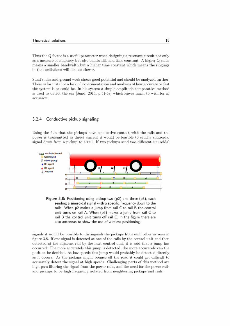
Figure 3.8: Positioning using pickup two (p2) and three (p3), eachsending a sinusoidal signal with a specific frequency down to therails. When p2 makes a jump from rail C to rail B the controlunit turns on rail A. When (p3) makes a jump from rail C torail B the control unit turns off rail C. In the figure there arealso antennas to show the use of wireless positioning.
signals it would be possible to distinguish the pickups from each other as seen infigure 3.8. If one signal is detected at one of the rails by the control unit and thendetected at the adjacent rail by the next control unit, it is said that a jump hasoccurred. The more accurately this jump is detected, the more accurately can theposition be decided. At low speeds this jump would probably be detected directlyas it occurs. As the pickups might bounce off the road it could get difficult toaccurately detect the signal at high speeds. Challenging parts of this method arehigh pass filtering the signal from the power rails, and the need for the power railsand pickups to be high frequency isolated from neighboring pickups and rails.
20 Theoretical solutions
3.2.5 Short circuit detectors on rail
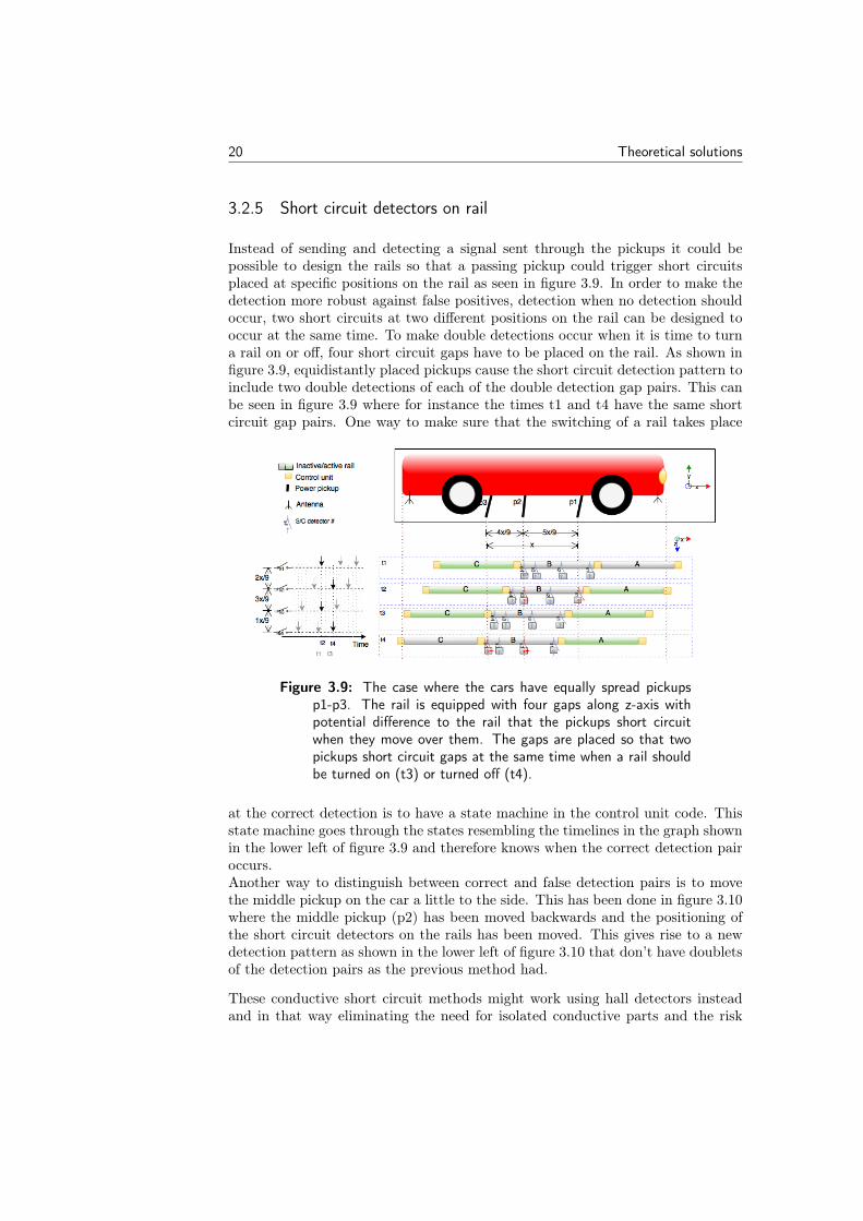
Instead of sending and detecting a signal sent through the pickups it could bepossible to design the rails so that a passing pickup could trigger short circuitsplaced at specific positions on the rail as seen in figure 3.9. In order to make thedetection more robust against false positives, detection when no detection shouldoccur, two short circuits at two different positions on the rail can be designed tooccur at the same time. To make double detections occur when it is time to turna rail on or off, four short circuit gaps have to be placed on the rail. As shown infigure 3.9, equidistantly placed pickups cause the short circuit detection pattern toinclude two double detections of each of the double detection gap pairs. This canbe seen in figure 3.9 where for instance the times t1 and t4 have the same shortcircuit gap pairs. One way to make sure that the switching of a rail takes place
Figure 3.9: The case where the cars have equally spread pickupsp1-p3. The rail is equipped with four gaps along z-axis withpotential difference to the rail that the pickups short circuitwhen they move over them. The gaps are placed so that twopickups short circuit gaps at the same time when a rail shouldbe turned on (t3) or turned off (t4).
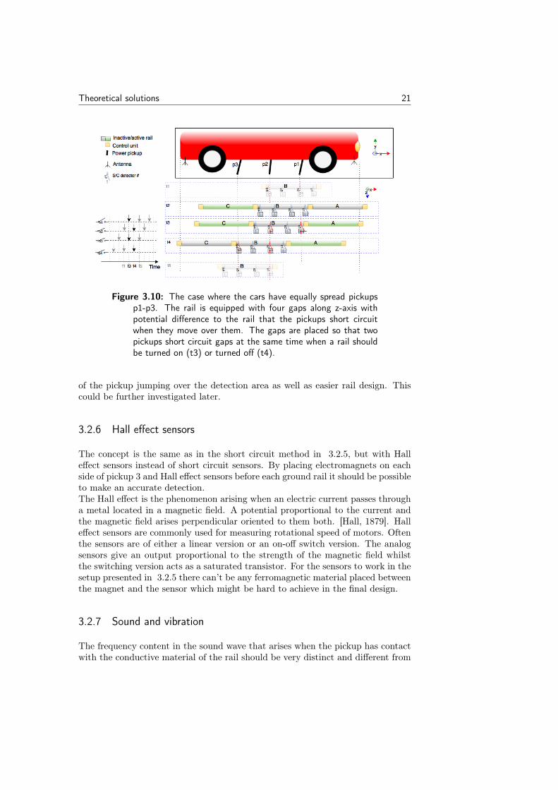
at the correct detection is to have a state machine in the control unit code. Thisstate machine goes through the states resembling the timelines in the graph shownin the lower left of figure 3.9 and therefore knows when the correct detection pairoccurs.Another way to distinguish between correct and false detection pairs is to movethe middle pickup on the car a little to the side. This has been done in figure 3.10where the middle pickup (p2) has been moved backwards and the positioning ofthe short circuit detectors on the rails has been moved. This gives rise to a newdetection pattern as shown in the lower left of figure 3.10 that don’t have doubletsof the detection pairs as the previous method had.
These conductive short circuit methods might work using hall detectors insteadand in that way eliminating the need for isolated conductive parts and the risk
Theoretical solutions 21
Figure 3.10: The case where the cars have equally spread pickupsp1-p3. The rail is equipped with four gaps along z-axis withpotential difference to the rail that the pickups short circuitwhen they move over them. The gaps are placed so that twopickups short circuit gaps at the same time when a rail shouldbe turned on (t3) or turned off (t4).
of the pickup jumping over the detection area as well as easier rail design. Thiscould be further investigated later.
3.2.6 Hall effect sensors
The concept is the same as in the short circuit method in 3.2.5, but with Halleffect sensors instead of short circuit sensors. By placing electromagnets on eachside of pickup 3 and Hall effect sensors before each ground rail it should be possibleto make an accurate detection.The Hall effect is the phenomenon arising when an electric current passes througha metal located in a magnetic field. A potential proportional to the current andthe magnetic field arises perpendicular oriented to them both. [Hall, 1879]. Halleffect sensors are commonly used for measuring rotational speed of motors. Oftenthe sensors are of either a linear version or an on-off switch version. The analogsensors give an output proportional to the strength of the magnetic field whilstthe switching version acts as a saturated transistor. For the sensors to work in thesetup presented in 3.2.5 there can’t be any ferromagnetic material placed betweenthe magnet and the sensor which might be hard to achieve in the final design.
3.2.7 Sound and vibration
The frequency content in the sound wave that arises when the pickup has contactwith the conductive material of the rail should be very distinct and different from
22 Theoretical solutions
that when the pickup has contact with the isolation material between the rails.It should be possible to determine when a pickup leaves and enters a rail usingone or more vibration sensors in the area around the isolator parts. It mightalso be possible to analyze the sound and see distinctive changes in the vibrationsdepending on how many pickups that are on the same rail. If the hardware andthe algorithm doing this can be made fast and cheap enough it is a possible wayfor precise detection. The method is however somewhat difficult to realize sinceno pickups have been designed or built yet to test this out on.
3.3 Different communication schemes
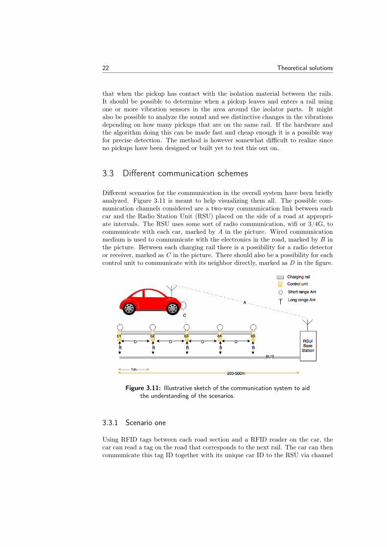
Different scenarios for the communication in the overall system have been brieflyanalyzed. Figure 3.11 is meant to help visualizing them all. The possible com-munication channels considered are a two-way communication link between eachcar and the Radio Station Unit (RSU) placed on the side of a road at appropri-ate intervals. The RSU uses some sort of radio communication, wifi or 3/4G, tocommunicate with each car, marked by A in the picture. Wired communicationmedium is used to communicate with the electronics in the road, marked by B inthe picture. Between each charging rail there is a possibility for a radio detectoror receiver, marked as C in the picture. There should also be a possibility for eachcontrol unit to communicate with its neighbor directly, marked as D in the figure.
Figure 3.11: Illustrative sketch of the communication system to aidthe understanding of the scenarios.
3.3.1 Scenario one
Using RFID tags between each road section and a RFID reader on the car, thecar can read a tag on the road that corresponds to the next rail. The car can thencommunicate this tag ID together with its unique car ID to the RSU via channel

Theoretical solutions 23
A. The RSU now has an uniquely identified car with a roughly accurate physicalposition. The RSU sends a signal to the corresponding rail control unit making itready to switch the rail on and off. The switching occurs when a detection, usingthe possible ways described in solutions for car positioning 3.2, is triggered. Inthis scenario the intelligence is centralized to the RSU and the control units areonly triggers controlling the switching of one rail. The RFID system is designedfor use of many tags and few readers.
The scenario needs a fast working RFID system and a fast working long rangecommunication so that the time from reading the RFID tag to switching the railis not exceeded. If a car is traveling at a speed of 200 km/h and the RFID tagis read one meter before the switch is triggered, that gives a total time of 18 ms.Since the detection occurs at the rail control unit the communication between thecar, RSU and rail control unit in this scenario doesn’t have to be deterministic, justperformed fast and reliably enough. Detection solutions thought of as appropriatefor this scenario, out of the brief analyzing done in solutions for car positioning3.2 are Hall effect sensors and inductive detection.
3.3.2 Scenario two
This scenario is very similar to the previous scenario, except the RFID readersare placed in the road and a tag is placed on the car. In other words, this oneway communication setup is the other way around from that in scenario one. Theapproaching car sends its own tag ID and a GPS position to the RSU. The RSUsends information about which tags are clear and accepted for use to all the railcontrol units in the vicinity of the GPS position. When the car tag ID is read bythe rail control unit the position is roughly confirmed and the upcoming rail canbe informed to get ready to be switched on, through communication link D. Theaccurate switching is again performed by one of the solutions from solutions forcar positioning 3.2.
In this scenario the key corresponding to a car is the RFID tag which is constantand hard to keep secret. This makes it hard to identify which car is activatingwhich rail in a satisfying manner. The RFID tags are also much cheaper than thereaders, this scenario resulting in a more expensive road. On the other side thisscenario doesn’t have the same constraints on the communication speed for eitherchannel A or B.
3.3.3 Scenario three
In this scenario the intelligence is distributed to the control units of each individualrail and there needs to be a two way communication link between car and controlunit at each individual rail. The rail identifies itself with a RFID tag and the carsends a rail unique code that the rail uses to both identify and position the car.The long range channel A is used to negotiate the unique codes and other essentialinformation. This scenario demands that the car is able to send a key and the

24 Theoretical solutions
speed, possibly around 32 + 8 bit, to a control unit at least 150 times per secondfor a radio range of around 0.5 m. This constraint is set by the maximum speedof 200 km/h and that a message should be sent at least three times to be receivedcorrectly.
There is no perfect way thought of in solutions for car positioning 3.2 to send somuch information from the car to the rail control unit and at the same time finda very accurate position at high speeds. Techniques that could be possible withmore analyzing and investigation could be Conductive pickup signaling, Identifyingantenna signal strength, inductive detection or Doppler effect. All of them mightbe hard to get to send enough information and at the same time accurately acquirethe position.
Chapter4Analysis and testing
4.1 Car positioning
One of the most promising methods in solutions for car positioning: 3.2 andalso the one which could be tested immediately was the inductive method. Anexperimental setup to do comparing experiments was built and calibrated, thendifferent antennas and frequencies were analyzed. Finally a detection system wasbuilt, implemented and tested outdoors.
4.1.1 Pendulum as experimental setup
In order to perform repeatable low speed tests in the laboratory a swing was builtconsisting of a rectangular wood plank suspended at the short ends as a swing.The length of the swinging pendulum measured from the pivot point to the centerof mass of the plank was 258 cm and the plank itself had a length and width of45 cm and 9.5 cm respectively. The height from the plank to the floor was about10 cm as seen in figure 4.1a. The energy of a swing at any point is the sum of thepotential and kinetic energy and this energy is conserved if the friction is neglected.Approximating the swing as a simple pendulum and setting up the energy balanceequations gives the following expression for the pendulum’s velocity at a height h:
Etot = mghstart = mgh+mv2
2⇔ v =
√2g(hstart − h)
where m is the mass the of the pendulum, g is the gravitational acceleration,hstart is the height from which the pendulum is released and v is the velocityat the height h. According to this equation the velocity of the pendulum at theequilibrium point is 4.43 m/s (15.95 km/h) when released from a height of 1 m(from the floor). This was approximately the highest speed tested with since itwas hard to manually release the pendulum from a higher height than this withoutit swinging sideways. For a more accurate velocity measurement and to get an
25
26 Analysis and testing
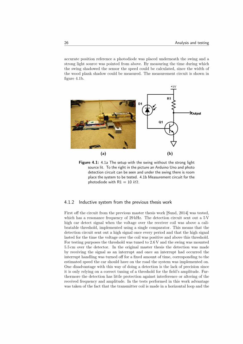
accurate position reference a photodiode was placed underneath the swing and astrong light source was pointed from above. By measuring the time during whichthe swing shadowed the sensor the speed could be calculated, since the width ofthe wood plank shadow could be measured. The measurement circuit is shown infigure 4.1b.
(a) (b)
Figure 4.1: 4.1a The setup with the swing without the strong lightsource lit. To the right in the picture an Arduino Uno and photodetection circuit can be seen and under the swing there is roomplace the system to be tested. 4.1b Measurement circuit for thephotodiode with R1 = 10 kΩ.
4.1.2 Inductive system from the previous thesis work
First off the circuit from the previous master thesis work [Sund, 2014] was tested,which has a resonance frequency of 29 kHz. The detection circuit sent out a 5 Vhigh car detect signal when the voltage over the receiver coil was above a cali-bratable threshold, implemented using a single comparator. This means that thedetection circuit sent out a high signal once every period and that the high signallasted for the time the voltage over the coil was positive and above this threshold.For testing purposes the threshold was tuned to 2.6 V and the swing was mounted5.5 cm over the detector. In the original master thesis the detection was madeby receiving the signal as an interrupt and once an interrupt had occurred theinterrupt handling was turned off for a fixed amount of time, corresponding to theestimated speed the car should have on the road the system was implemented on.One disadvantage with this way of doing a detection is the lack of precision sinceit is only relying on a correct tuning of a threshold for the field’s amplitude. Fur-thermore the detection has little protection against interference or altering of thereceived frequency and amplitude. In the tests performed in this work advantagewas taken of the fact that the transmitter coil is made in a horizontal loop and the
Analysis and testing 27
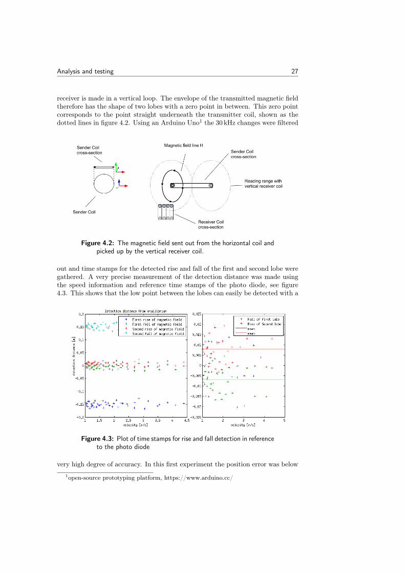
receiver is made in a vertical loop. The envelope of the transmitted magnetic fieldtherefore has the shape of two lobes with a zero point in between. This zero pointcorresponds to the point straight underneath the transmitter coil, shown as thedotted lines in figure 4.2. Using an Arduino Uno1 the 30 kHz changes were filtered
Figure 4.2: The magnetic field sent out from the horizontal coil andpicked up by the vertical receiver coil.
out and time stamps for the detected rise and fall of the first and second lobe weregathered. A very precise measurement of the detection distance was made usingthe speed information and reference time stamps of the photo diode, see figure4.3. This shows that the low point between the lobes can easily be detected with a
Figure 4.3: Plot of time stamps for rise and fall detection in referenceto the photo diode
very high degree of accuracy. In this first experiment the position error was below
1open-source prototyping platform, https://www.arduino.cc/
28 Analysis and testing
1 cm. The maximum theoretical speed of this method is limited by the rise timeof the magnetic field since the magnetic field strength has to rise high enough fora change to be detectable. The point between the two lobes should always existsince the two lobes have a half period phase shift to each other and therefore thesignal always has to pass a point with zero magnetic field.
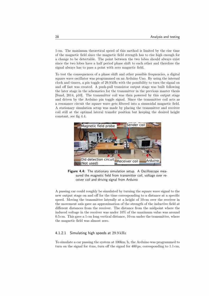
To test the consequences of a phase shift and other possible frequencies, a digitalsquare wave oscillator was programmed on an Arduino Uno. By using the internalclock and timers, a pin toggle of 29.9 kHz with the possibility to turn the signal onand off fast was created. A push-pull transistor output stage was built followingthe later stage in the schematics for the transmitter in the previous master thesis[Sund, 2014, p10]. The transmitter coil was then powered by this output stageand driven by the Arduino pin toggle signal. Since the transmitter coil acts asa resonance circuit the square wave gets filtered into a sinusoidal magnetic field.A stationary simulation setup was made by placing the transmitter and receivercoil still at the optimal lateral transfer position but keeping the desired heightconstant, see fig 4.4.
Figure 4.4: The stationary simulation setup. A Oscilloscope mea-sured the magnetic field from transmitter coil, voltage over re-ceiver coil and driving signal from Arduino
A passing car could roughly be simulated by turning the square wave signal to thenew output stage on and off for the time corresponding to a distance at a specificspeed. Moving the transmitter laterally at a height of 10 cm over the receiver inthe movement axis gave an approximation of the strength of the inductive field atdifferent distances from the receiver. The distance from the midpoint where theinduced voltage in the receiver was under 10% of the maximum value was around0.5 cm. This gave a 1 cm long vertical distance, 10 cm under the transmitter, wherethe magnetic field was almost zero.
4.1.2.1 Simulating high speeds at 29.9 kHz
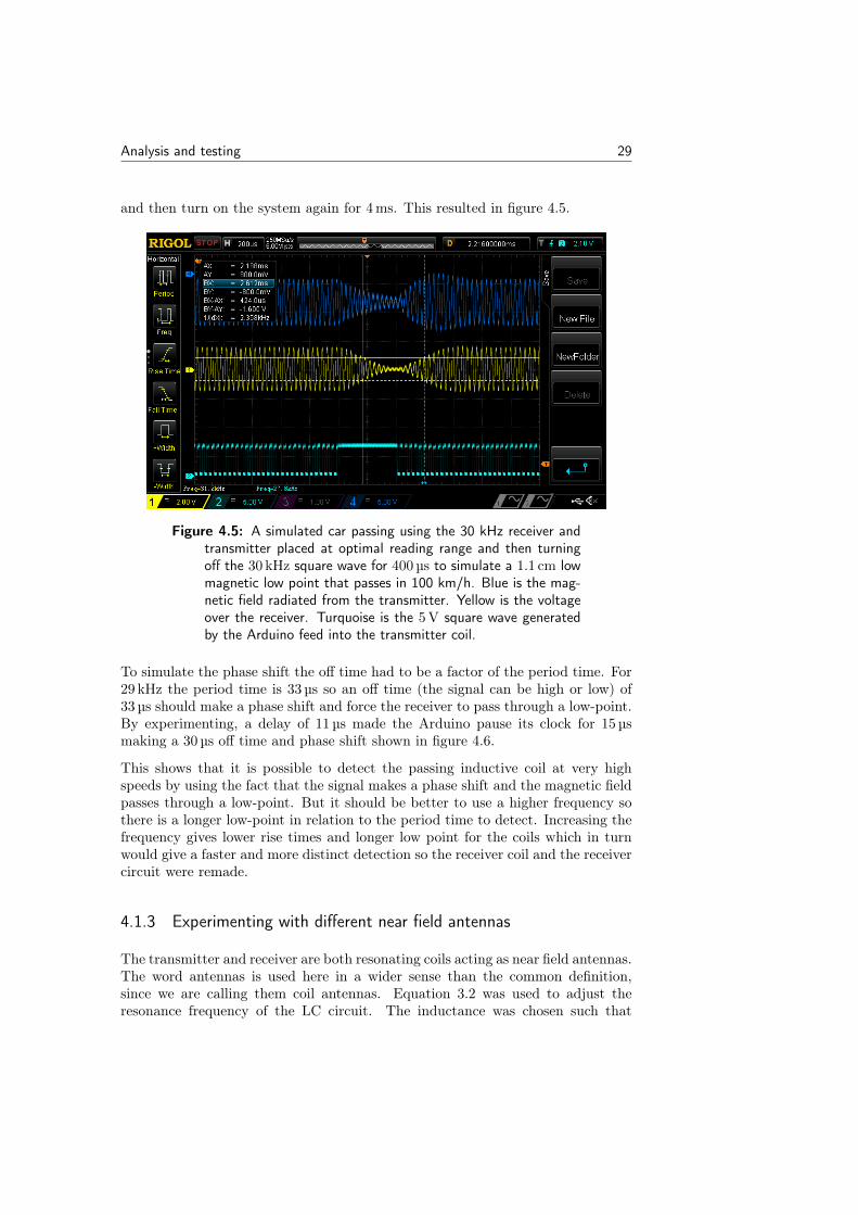
To simulate a car passing the system at 100km/h, the Arduino was programmed toturn on the signal for 4 ms, turn off the signal for 400 µs, corresponding to 1.1 cm,
Analysis and testing 29
and then turn on the system again for 4 ms. This resulted in figure 4.5.
Figure 4.5: A simulated car passing using the 30 kHz receiver andtransmitter placed at optimal reading range and then turningoff the 30 kHz square wave for 400 µs to simulate a 1.1 cm lowmagnetic low point that passes in 100 km/h. Blue is the mag-netic field radiated from the transmitter. Yellow is the voltageover the receiver. Turquoise is the 5 V square wave generatedby the Arduino feed into the transmitter coil.
To simulate the phase shift the off time had to be a factor of the period time. For29 kHz the period time is 33 µs so an off time (the signal can be high or low) of33 µs should make a phase shift and force the receiver to pass through a low-point.By experimenting, a delay of 11 µs made the Arduino pause its clock for 15 µsmaking a 30 µs off time and phase shift shown in figure 4.6.
This shows that it is possible to detect the passing inductive coil at very highspeeds by using the fact that the signal makes a phase shift and the magnetic fieldpasses through a low-point. But it should be better to use a higher frequency sothere is a longer low-point in relation to the period time to detect. Increasing thefrequency gives lower rise times and longer low point for the coils which in turnwould give a faster and more distinct detection so the receiver coil and the receivercircuit were remade.
4.1.3 Experimenting with different near field antennas
The transmitter and receiver are both resonating coils acting as near field antennas.The word antennas is used here in a wider sense than the common definition,since we are calling them coil antennas. Equation 3.2 was used to adjust theresonance frequency of the LC circuit. The inductance was chosen such that
30 Analysis and testing
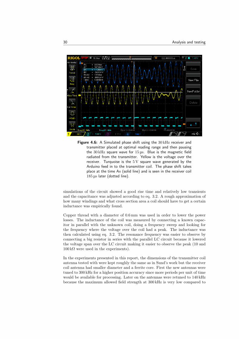
Figure 4.6: A Simulated phase shift using the 30 kHz receiver andtransmitter placed at optimal reading range and then pausingthe 30 kHz square wave for 15 µs. Blue is the magnetic fieldradiated from the transmitter. Yellow is the voltage over thereceiver. Turquoise is the 5 V square wave generated by theArduino feed in to the transmitter coil. The phase shift takesplace at the time Ax (solid line) and is seen in the receiver coil185 µs later (dotted line).
simulations of the circuit showed a good rise time and relatively low transientsand the capacitance was adjusted according to eq. 3.2. A rough approximation ofhow many windings and what cross section area a coil should have to get a certaininductance was empirically found.
Copper thread with a diameter of 0.6 mm was used in order to lower the powerlosses. The inductance of the coil was measured by connecting a known capac-itor in parallel with the unknown coil, doing a frequency sweep and looking forthe frequency where the voltage over the coil had a peak. The inductance wasthen calculated using eq. 3.2. The resonance frequency was easier to observe byconnecting a big resistor in series with the parallel LC circuit because it loweredthe voltage span over the LC circuit making it easier to observe the peak (10 and100 kΩ were used in the experiments).
In the experiments presented in this report, the dimensions of the transmitter coilantenna tested with were kept roughly the same as in Sund’s work but the receivercoil antenna had smaller diameter and a ferrite core. First the new antennas weretuned to 300 kHz for a higher position accuracy since more periods per unit of timewould be available for processing. Later on the antennas were retuned to 140 kHzbecause the maximum allowed field strength at 300 kHz is very low compared to
Analysis and testing 31
around 9−148 kHz [PTSFS, 2015, p.13]. And since the chosen RFID system runson 125 kHz, 140 kHz seemed like a good frequency to aim for. The maximumallowed field strength at 140 kHz and a distance of 10 m from the antenna is 42dB uA/m [PTSFS, 2015, p.13]. This corresponds to 0.158 nT:
42 dB µA/m = 20 · log(H
1 µA/m)
⇔ H = 125.892 µA/m
⇔ B = µ0µrH = 0.158 nT.
4.1.4 Simulating, testing and building
The 140 kHz system consists of a transmitter stage and a receiver stage. As thetransmitter stage an Arduino Uno acts as a signal generator and together with atransmitter antenna the sending stage is to be mounted underneath a car. Thereceiving stage consists of a receiver antenna, rectifier electronics and an ArduinoDue2 with an Ethernet and SD-card reader shield3. The receiver antenna, elec-tronics and Arduino are to be put inside a road segment mock-up with LED lightson it. Instead of delivering power to a passing car, the segment lights up its LEDlights when the car passes.
4.1.4.1 Receiver and transmitter antennas
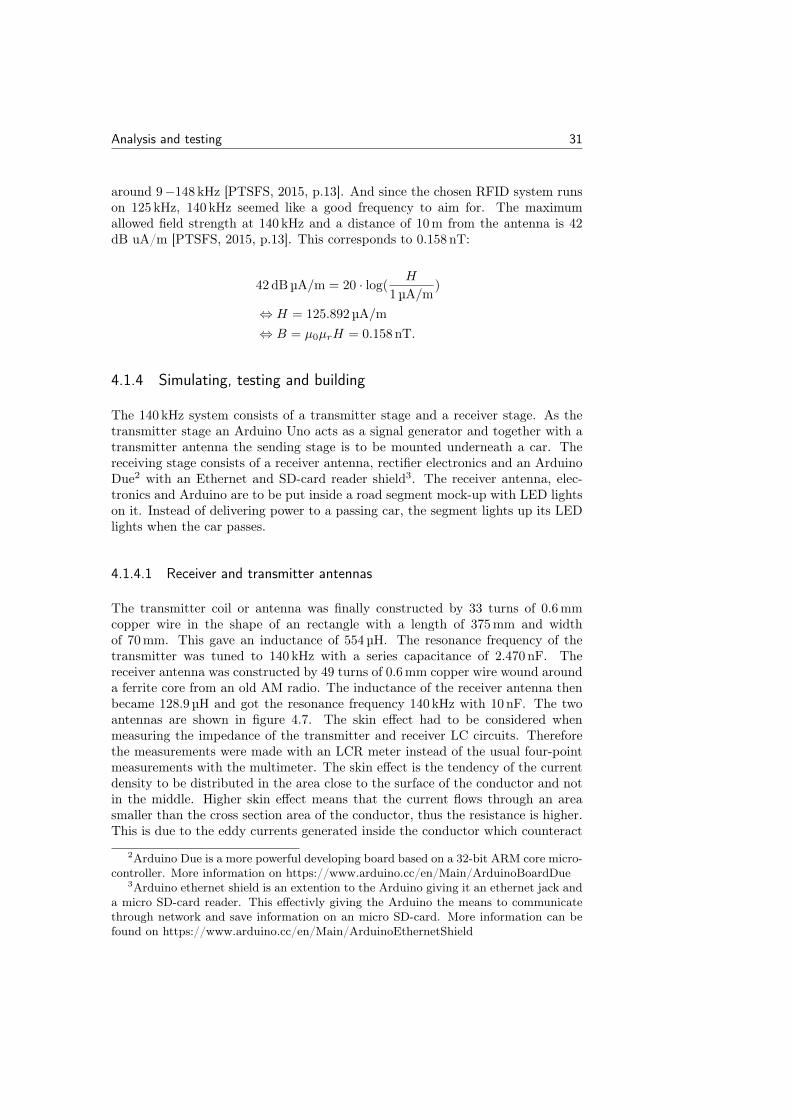
The transmitter coil or antenna was finally constructed by 33 turns of 0.6 mmcopper wire in the shape of an rectangle with a length of 375 mm and widthof 70 mm. This gave an inductance of 554 µH. The resonance frequency of thetransmitter was tuned to 140 kHz with a series capacitance of 2.470 nF. Thereceiver antenna was constructed by 49 turns of 0.6 mm copper wire wound arounda ferrite core from an old AM radio. The inductance of the receiver antenna thenbecame 128.9 µH and got the resonance frequency 140 kHz with 10 nF. The twoantennas are shown in figure 4.7. The skin effect had to be considered whenmeasuring the impedance of the transmitter and receiver LC circuits. Thereforethe measurements were made with an LCR meter instead of the usual four-pointmeasurements with the multimeter. The skin effect is the tendency of the currentdensity to be distributed in the area close to the surface of the conductor and notin the middle. Higher skin effect means that the current flows through an areasmaller than the cross section area of the conductor, thus the resistance is higher.This is due to the eddy currents generated inside the conductor which counteract
2Arduino Due is a more powerful developing board based on a 32-bit ARM core micro-controller. More information on https://www.arduino.cc/en/Main/ArduinoBoardDue
3Arduino ethernet shield is an extention to the Arduino giving it an ethernet jack anda micro SD-card reader. This effectivly giving the Arduino the means to communicatethrough network and save information on an micro SD-card. More information can befound on https://www.arduino.cc/en/Main/ArduinoEthernetShield
32 Analysis and testing
Figure 4.7: The transmitter (top one in picture) and receiver an-tenna, at an earlier resonance tuning. The dimensions andshape are the same as in the chosen 140 kHz setup. Only thenumber of windings and the tuning capacitance value differ.
the current in the middle of the conductor. The skin depth in a copper wire canbe calculated according to:
δ =
√2
ωµrµ0σ
where µ0 is the magnetic permeability of free space µ0 = 4π · 10−7T · m/A, µr
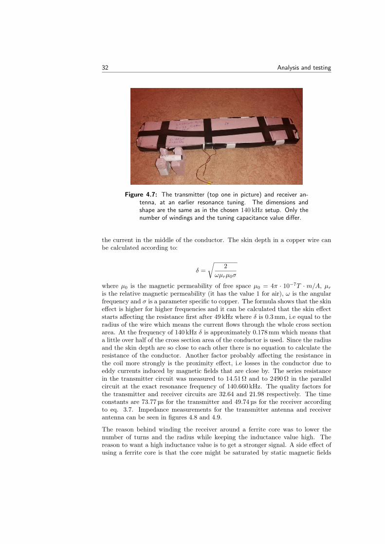
is the relative magnetic permeability (it has the value 1 for air), ω is the angularfrequency and σ is a parameter specific to copper. The formula shows that the skineffect is higher for higher frequencies and it can be calculated that the skin effectstarts affecting the resistance first after 49 kHz where δ is 0.3 mm, i.e equal to theradius of the wire which means the current flows through the whole cross sectionarea. At the frequency of 140 kHz δ is approximately 0.178 mm which means thata little over half of the cross section area of the conductor is used. Since the radiusand the skin depth are so close to each other there is no equation to calculate theresistance of the conductor. Another factor probably affecting the resistance inthe coil more strongly is the proximity effect, i.e losses in the conductor due toeddy currents induced by magnetic fields that are close by. The series resistancein the transmitter circuit was measured to 14.51 Ω and to 2490 Ω in the parallelcircuit at the exact resonance frequency of 140.660 kHz. The quality factors forthe transmitter and receiver circuits are 32.64 and 21.98 respectively. The timeconstants are 73.77 µs for the transmitter and 49.74 µs for the receiver accordingto eq. 3.7. Impedance measurements for the transmitter antenna and receiverantenna can be seen in figures 4.8 and 4.9.
The reason behind winding the receiver around a ferrite core was to lower thenumber of turns and the radius while keeping the inductance value high. Thereason to want a high inductance value is to get a stronger signal. A side effect ofusing a ferrite core is that the core might be saturated by static magnetic fields
Analysis and testing 33
(a) (b)
Figure 4.8: Bandwidth of the tuned transmitter antenna. The band-width is approximately 4 kHz
(a) (b)
Figure 4.9: Bandwidth of the tuned receiver antenna. The band-width is approximately 6.5 kHz
from the electrical road. To test the affect the current of the road will have onthe signal strength in the inductive detection an experiment was made. The aimof the experiment is to see how a neodymium magnet at different distances affectsthe amplitude of the induced voltage in the receiver antenna.
4.1.4.2 Test of static magnetic impact on ferrite core
To test the effect a strong magnetic field would have on the 140 kHz induced voltagein the receiver antenna, a neodymium magnet was used and placed at differentdistances from the receiver. The receiver was placed at optimal reading range fromthe transmitter. A square wave generated by an Arduino Uno was sent as inputto the transmitter and the induced amplitude was measured while the magnet wasplaced at different heights from the receiver, see figure 4.10.
34 Analysis and testing
(a) (b)
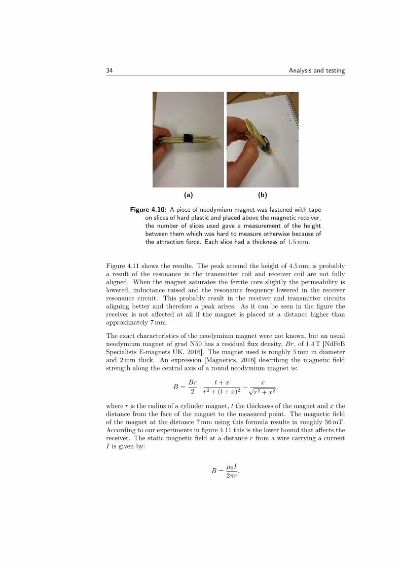
Figure 4.10: A piece of neodymium magnet was fastened with tapeon slices of hard plastic and placed above the magnetic receiver,the number of slices used gave a measurement of the heightbetween them which was hard to measure otherwise because ofthe attraction force. Each slice had a thickness of 1.5 mm.
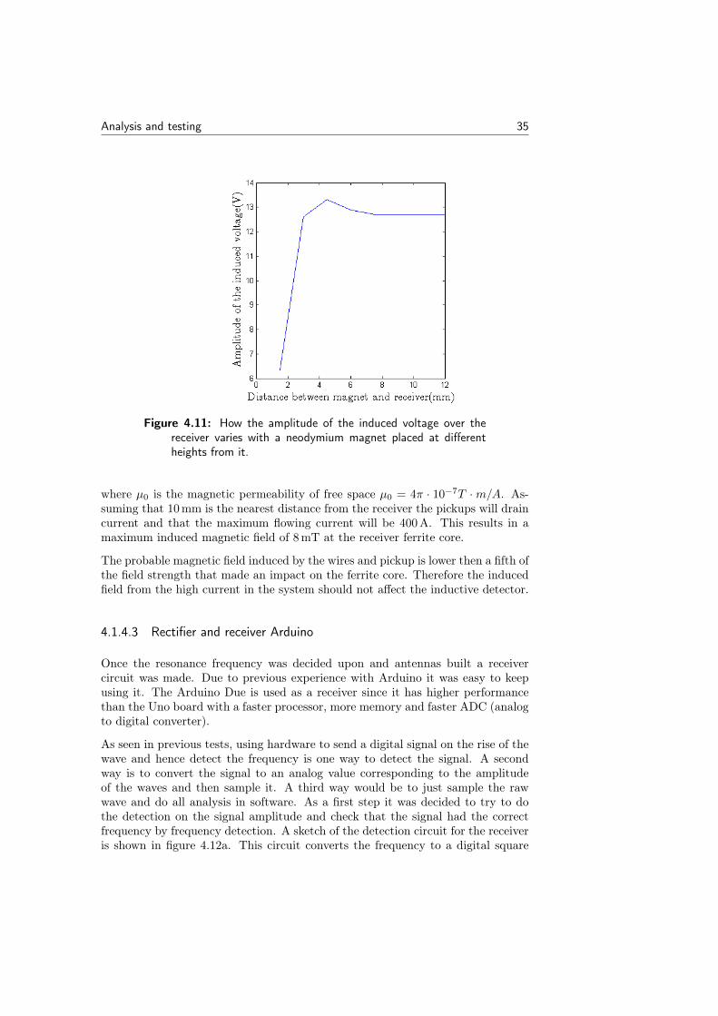
Figure 4.11 shows the results. The peak around the height of 4.5 mm is probablya result of the resonance in the transmitter coil and receiver coil are not fullyaligned. When the magnet saturates the ferrite core slightly the permeability islowered, inductance raised and the resonance frequency lowered in the receiverresonance circuit. This probably result in the receiver and transmitter circuitsaligning better and therefore a peak arises. As it can be seen in the figure thereceiver is not affected at all if the magnet is placed at a distance higher thanapproximately 7 mm.
The exact characteristics of the neodymium magnet were not known, but an usualneodymium magnet of grad N50 has a residual flux density, Br, of 1.4 T [NdFeBSpecialists E-magnets UK, 2016]. The magnet used is roughly 5 mm in diameterand 2 mm thick. An expression [Magnetics, 2016] describing the magnetic fieldstrength along the central axis of a round neodymium magnet is:
B =Br
2· t+ x
r2 + (t+ x)2− x√
r2 + x2,
where r is the radius of a cylinder magnet, t the thickness of the magnet and x thedistance from the face of the magnet to the measured point. The magnetic fieldof the magnet at the distance 7 mm using this formula results in roughly 56 mT.According to our experiments in figure 4.11 this is the lower bound that affects thereceiver. The static magnetic field at a distance r from a wire carrying a currentI is given by:
B =µ0I
2πr,
Analysis and testing 35
Figure 4.11: How the amplitude of the induced voltage over thereceiver varies with a neodymium magnet placed at differentheights from it.
where µ0 is the magnetic permeability of free space µ0 = 4π · 10−7T ·m/A. As-suming that 10 mm is the nearest distance from the receiver the pickups will draincurrent and that the maximum flowing current will be 400 A. This results in amaximum induced magnetic field of 8 mT at the receiver ferrite core.
The probable magnetic field induced by the wires and pickup is lower then a fifth ofthe field strength that made an impact on the ferrite core. Therefore the inducedfield from the high current in the system should not affect the inductive detector.
4.1.4.3 Rectifier and receiver Arduino
Once the resonance frequency was decided upon and antennas built a receivercircuit was made. Due to previous experience with Arduino it was easy to keepusing it. The Arduino Due is used as a receiver since it has higher performancethan the Uno board with a faster processor, more memory and faster ADC (analogto digital converter).
As seen in previous tests, using hardware to send a digital signal on the rise of thewave and hence detect the frequency is one way to detect the signal. A secondway is to convert the signal to an analog value corresponding to the amplitudeof the waves and then sample it. A third way would be to just sample the rawwave and do all analysis in software. As a first step it was decided to try to dothe detection on the signal amplitude and check that the signal had the correctfrequency by frequency detection. A sketch of the detection circuit for the receiveris shown in figure 4.12a. This circuit converts the frequency to a digital square
36 Analysis and testing
wave and the amplitude to an analog value which could be read using the ADC.The Arduino Due can only handle voltages up to 3.3V so both circuits are builtto have an output in the 0-3.3V range. The frequency analyzing was howevernever implemented in code since the bandwidth of the antennas was so narrowand the detection algorithm works satisfactory using only amplitude information.The inductance in the transmitter antenna was near the lower acceptable limit,
(a) (b)
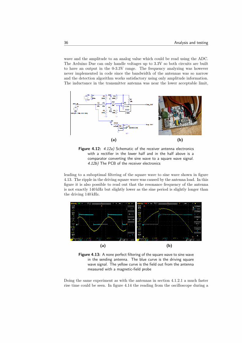
Figure 4.12: 4.12a) Schematic of the receiver antenna electronicswith a rectifier in the lower half and in the half above is acomparator converting the sine wave to a square wave signal.4.12b) The PCB of the receiver electronics
leading to a suboptimal filtering of the square wave to sine wave shown in figure4.13. The ripple in the driving square wave was caused by the antenna load. In thisfigure it is also possible to read out that the resonance frequency of the antennais not exactly 140 kHz but slightly lower as the sine period is slightly longer thanthe driving 140 kHz.
(a) (b)
Figure 4.13: A none perfect filtering of the square wave to sine wavein the sending antenna. The blue curve is the driving squarewave signal. The yellow curve is the field out from the antennameasured with a magnetic-field probe
Doing the same experiment as with the antennas in section 4.1.2.1 a much fasterrise time could be seen. In figure 4.14 the reading from the oscilloscope during a
Analysis and testing 37
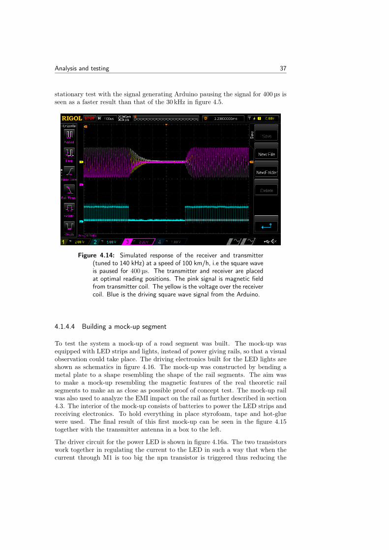
stationary test with the signal generating Arduino pausing the signal for 400 µs isseen as a faster result than that of the 30 kHz in figure 4.5.
Figure 4.14: Simulated response of the receiver and transmitter(tuned to 140 kHz) at a speed of 100 km/h, i.e the square waveis paused for 400 µs. The transmitter and receiver are placedat optimal reading positions. The pink signal is magnetic fieldfrom transmitter coil. The yellow is the voltage over the receivercoil. Blue is the driving square wave signal from the Arduino.
4.1.4.4 Building a mock-up segment
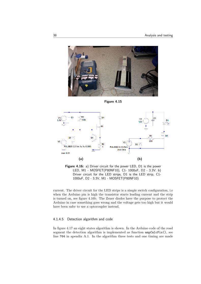
To test the system a mock-up of a road segment was built. The mock-up wasequipped with LED strips and lights, instead of power giving rails, so that a visualobservation could take place. The driving electronics built for the LED lights areshown as schematics in figure 4.16. The mock-up was constructed by bending ametal plate to a shape resembling the shape of the rail segments. The aim wasto make a mock-up resembling the magnetic features of the real theoretic railsegments to make an as close as possible proof of concept test. The mock-up railwas also used to analyze the EMI impact on the rail as further described in section4.3. The interior of the mock-up consists of batteries to power the LED strips andreceiving electronics. To hold everything in place styrofoam, tape and hot-gluewere used. The final result of this first mock-up can be seen in the figure 4.15together with the transmitter antenna in a box to the left.
The driver circuit for the power LED is shown in figure 4.16a. The two transistorswork together in regulating the current to the LED in such a way that when thecurrent through M1 is too big the npn transistor is triggered thus reducing the
38 Analysis and testing
Figure 4.15
(a) (b)
Figure 4.16: a) Driver circuit for the power LED, D1 is the powerLED, M1 - MOSFET(P80NF10), C1- 1000uF, D2 - 3.3V. b)Driver circuit for the LED strips, D1 is the LED strip, C1-1000uF, D2 - 3.3V, M1 - MOSFET(P80NF10)
current. The driver circuit for the LED strips is a simple switch configuration, i.ewhen the Arduino pin is high the transistor starts leading current and the stripis turned on, see figure 4.16b. The Zener diodes have the purpose to protect theArduino in case something goes wrong and the voltage gets too high but it wouldhave been safer to use a optocoupler instead.
4.1.4.5 Detection algorithm and code
In figure 4.17 an eight states algorithm is shown. In the Arduino code of the roadsegment the detection algorithm is implemented as function ampCalcFix(), seeline 764 in apendix A.1. In the algorithm three tests and one timing are made
Analysis and testing 39
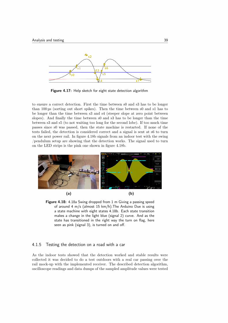
Figure 4.17: Help sketch for eight state detection algorithm
to ensure a correct detection. First the time between s0 and s3 has to be longerthan 100 µs (sorting out short spikes). Then the time between s0 and s1 has tobe longer than the time between s3 and s4 (steeper slope at zero point betweenslopes). And finally the time between s0 and s3 has to be longer than the timebetween s3 and s5 (to not waiting too long for the second lobe). If too much timepasses since s0 was passed, then the state machine is restarted. If none of thetests failed, the detection is considered correct and a signal is sent at s6 to turnon the next power rail. In figure 4.18b signals from an indoor test with the swing/pendulum setup are showing that the detection works. The signal used to turnon the LED strips is the pink one shown in figure 4.18b.
(a) (b)
Figure 4.18: 4.18a Swing dropped from 1 m Giving a passing speedof around 4 m/s (almost 15 km/h).The Arduino Due is usinga state machine with eight states 4.18b. Each state transitionmakes a change in the light blue (signal 2) curve. And as thestate has transitioned in the right way the turn on flag, hereseen as pink (signal 3), is turned on and off.
4.1.5 Testing the detection on a road with a car
As the indoor tests showed that the detection worked and stable results werecollected it was decided to do a test outdoors with a real car passing over therail mock-up with the implemented receiver. The described detection algorithm,oscilloscope readings and data dumps of the sampled amplitude values were tested
40 Analysis and testing
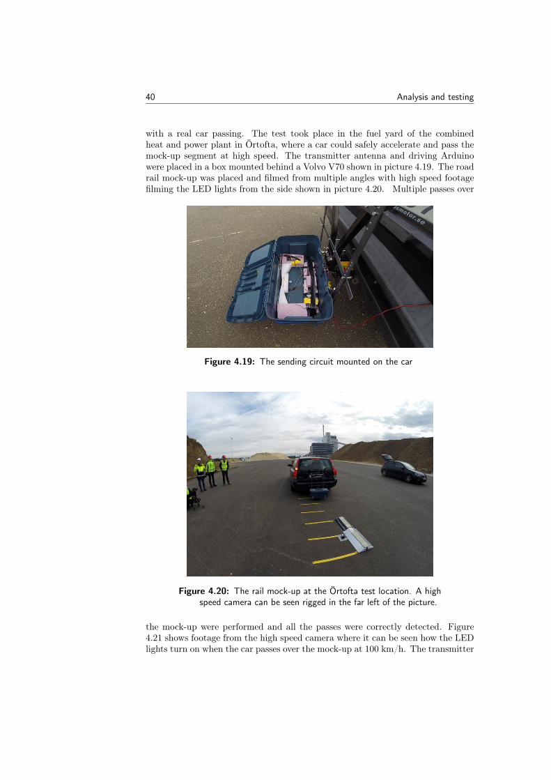
with a real car passing. The test took place in the fuel yard of the combinedheat and power plant in Örtofta, where a car could safely accelerate and pass themock-up segment at high speed. The transmitter antenna and driving Arduinowere placed in a box mounted behind a Volvo V70 shown in picture 4.19. The roadrail mock-up was placed and filmed from multiple angles with high speed footagefilming the LED lights from the side shown in picture 4.20. Multiple passes over
Figure 4.19: The sending circuit mounted on the car
Figure 4.20: The rail mock-up at the Örtofta test location. A highspeed camera can be seen rigged in the far left of the picture.
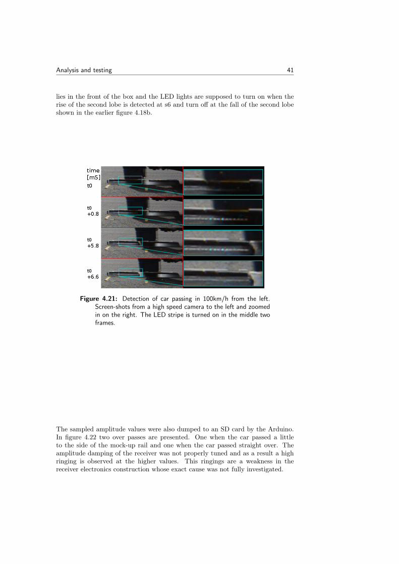
the mock-up were performed and all the passes were correctly detected. Figure4.21 shows footage from the high speed camera where it can be seen how the LEDlights turn on when the car passes over the mock-up at 100 km/h. The transmitter
Analysis and testing 41
lies in the front of the box and the LED lights are supposed to turn on when therise of the second lobe is detected at s6 and turn off at the fall of the second lobeshown in the earlier figure 4.18b.
Figure 4.21: Detection of car passing in 100km/h from the left.Screen-shots from a high speed camera to the left and zoomedin on the right. The LED stripe is turned on in the middle twoframes.
The sampled amplitude values were also dumped to an SD card by the Arduino.In figure 4.22 two over passes are presented. One when the car passed a littleto the side of the mock-up rail and one when the car passed straight over. Theamplitude damping of the receiver was not properly tuned and as a result a highringing is observed at the higher values. This ringings are a weakness in thereceiver electronics construction whose exact cause was not fully investigated.
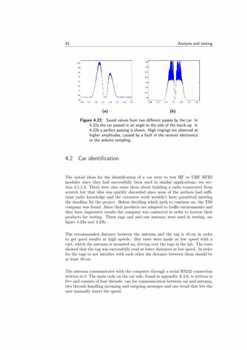
42 Analysis and testing
(a) (b)
Figure 4.22: Saved values from two different passes by the car. In4.22a the car passed in an angle to the side of the mock-up. In4.22b a perfect passing is shown. High ringings are observed athigher amplitudes, caused by a fault in the receiver electronicsor the arduino sampling.
4.2 Car identification
The initial ideas for the identification of a car were to test HF or UHF RFIDmodules since they had successfully been used in similar applications, see sec-tion 3.1.1.3. There were also some ideas about building a radio transceiver fromscratch but that idea was quickly discarded since none of the authors had suffi-cient radio knowledge and the extensive work wouldn’t have permitted meetingthe deadline for the project. Before deciding which path to continue on, the TSScompany was found. Since their products are adapted to traffic environments andthey have impressive results the company was contacted in order to borrow theirproducts for testing. Three tags and and one antenna were used in testing, seefigure 4.23a and 4.23b.
The recommended distance between the antenna and the tag is 45 cm in orderto get good results at high speeds. But tests were made at low speed with acart, which the antenna is mounted on, driving over the tags in the lab. The testsshowed that the tag was successfully read at lower distances at low speed. In orderfor the tags to not interfere with each other the distance between them should beat least 40 cm.
The antenna communicates with the computer through a serial RS232 connectionwritten in C. The main code on the car side, found in appendix A.2.6, is written inC++ and consists of four threads: one for communication between car and antenna,two threads handling incoming and outgoing messages and one tread that lets theuser manually insert the speed.
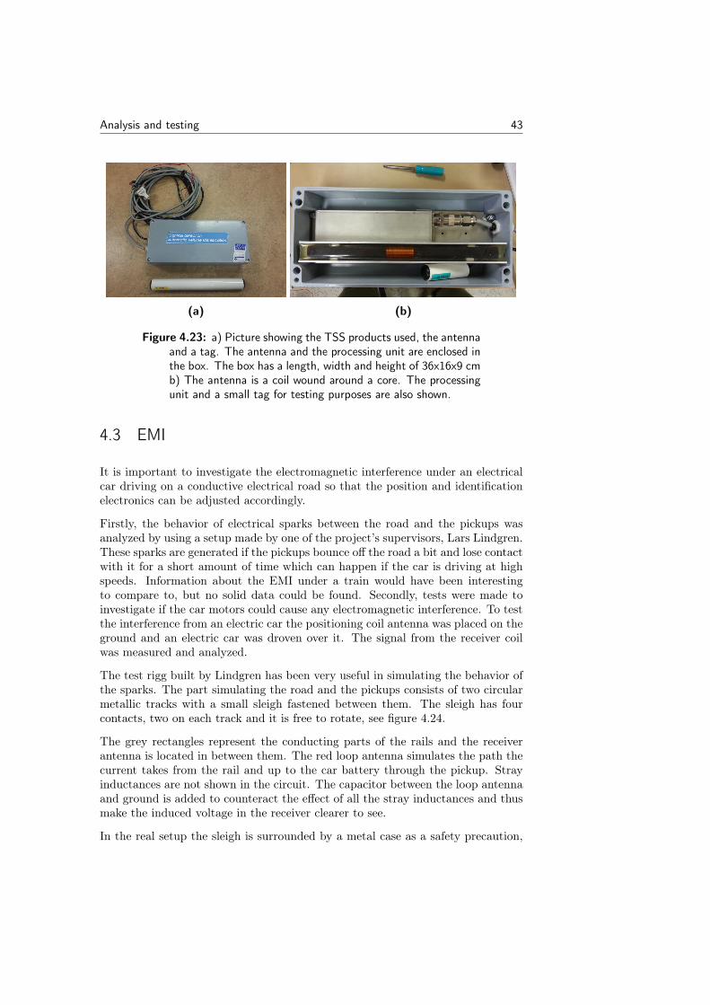
Analysis and testing 43
(a) (b)
Figure 4.23: a) Picture showing the TSS products used, the antennaand a tag. The antenna and the processing unit are enclosed inthe box. The box has a length, width and height of 36x16x9 cmb) The antenna is a coil wound around a core. The processingunit and a small tag for testing purposes are also shown.
4.3 EMI
It is important to investigate the electromagnetic interference under an electricalcar driving on a conductive electrical road so that the position and identificationelectronics can be adjusted accordingly.
Firstly, the behavior of electrical sparks between the road and the pickups wasanalyzed by using a setup made by one of the project’s supervisors, Lars Lindgren.These sparks are generated if the pickups bounce off the road a bit and lose contactwith it for a short amount of time which can happen if the car is driving at highspeeds. Information about the EMI under a train would have been interestingto compare to, but no solid data could be found. Secondly, tests were made toinvestigate if the car motors could cause any electromagnetic interference. To testthe interference from an electric car the positioning coil antenna was placed on theground and an electric car was droven over it. The signal from the receiver coilwas measured and analyzed.
The test rigg built by Lindgren has been very useful in simulating the behavior ofthe sparks. The part simulating the road and the pickups consists of two circularmetallic tracks with a small sleigh fastened between them. The sleigh has fourcontacts, two on each track and it is free to rotate, see figure 4.24.
The grey rectangles represent the conducting parts of the rails and the receiverantenna is located in between them. The red loop antenna simulates the path thecurrent takes from the rail and up to the car battery through the pickup. Strayinductances are not shown in the circuit. The capacitor between the loop antennaand ground is added to counteract the effect of all the stray inductances and thusmake the induced voltage in the receiver clearer to see.
In the real setup the sleigh is surrounded by a metal case as a safety precaution,
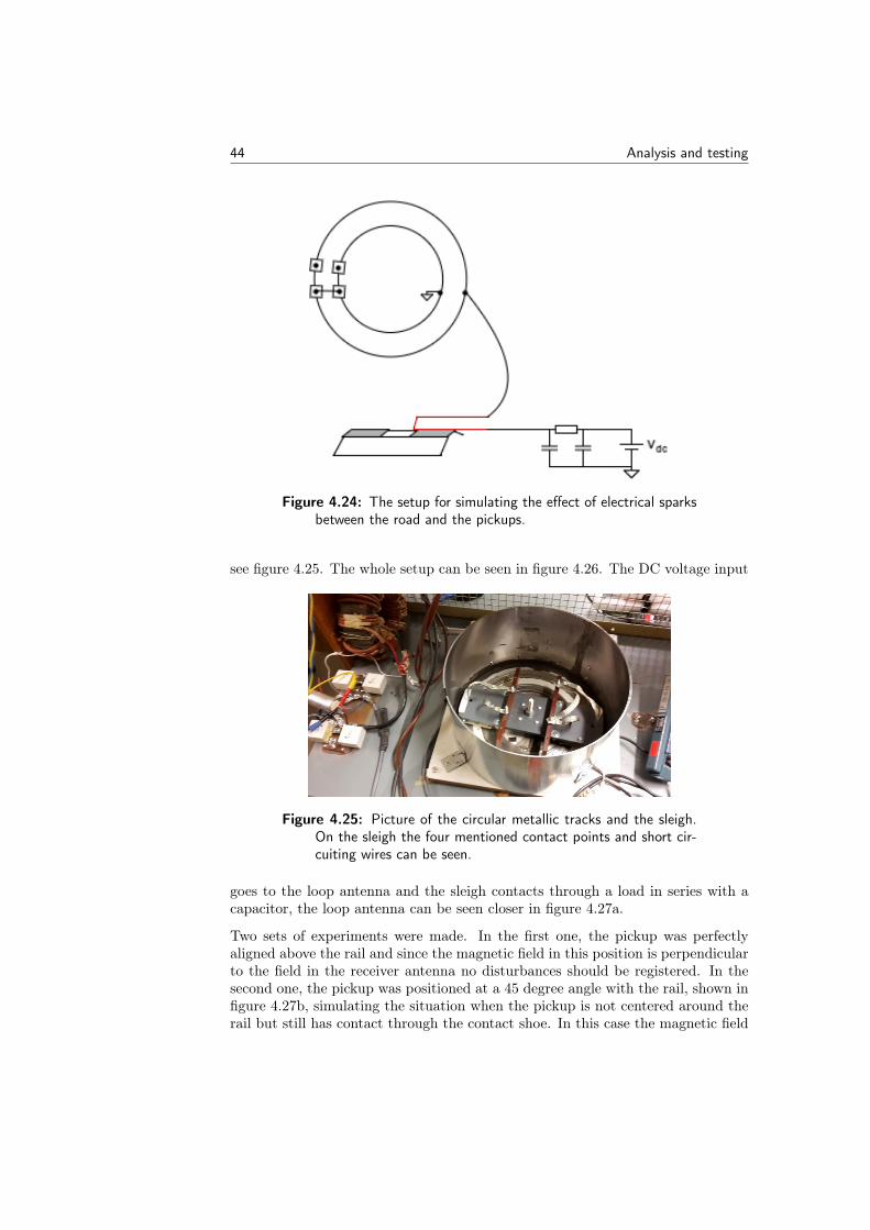
44 Analysis and testing
Figure 4.24: The setup for simulating the effect of electrical sparksbetween the road and the pickups.
see figure 4.25. The whole setup can be seen in figure 4.26. The DC voltage input
Figure 4.25: Picture of the circular metallic tracks and the sleigh.On the sleigh the four mentioned contact points and short cir-cuiting wires can be seen.
goes to the loop antenna and the sleigh contacts through a load in series with acapacitor, the loop antenna can be seen closer in figure 4.27a.
Two sets of experiments were made. In the first one, the pickup was perfectlyaligned above the rail and since the magnetic field in this position is perpendicularto the field in the receiver antenna no disturbances should be registered. In thesecond one, the pickup was positioned at a 45 degree angle with the rail, shown infigure 4.27b, simulating the situation when the pickup is not centered around therail but still has contact through the contact shoe. In this case the magnetic field
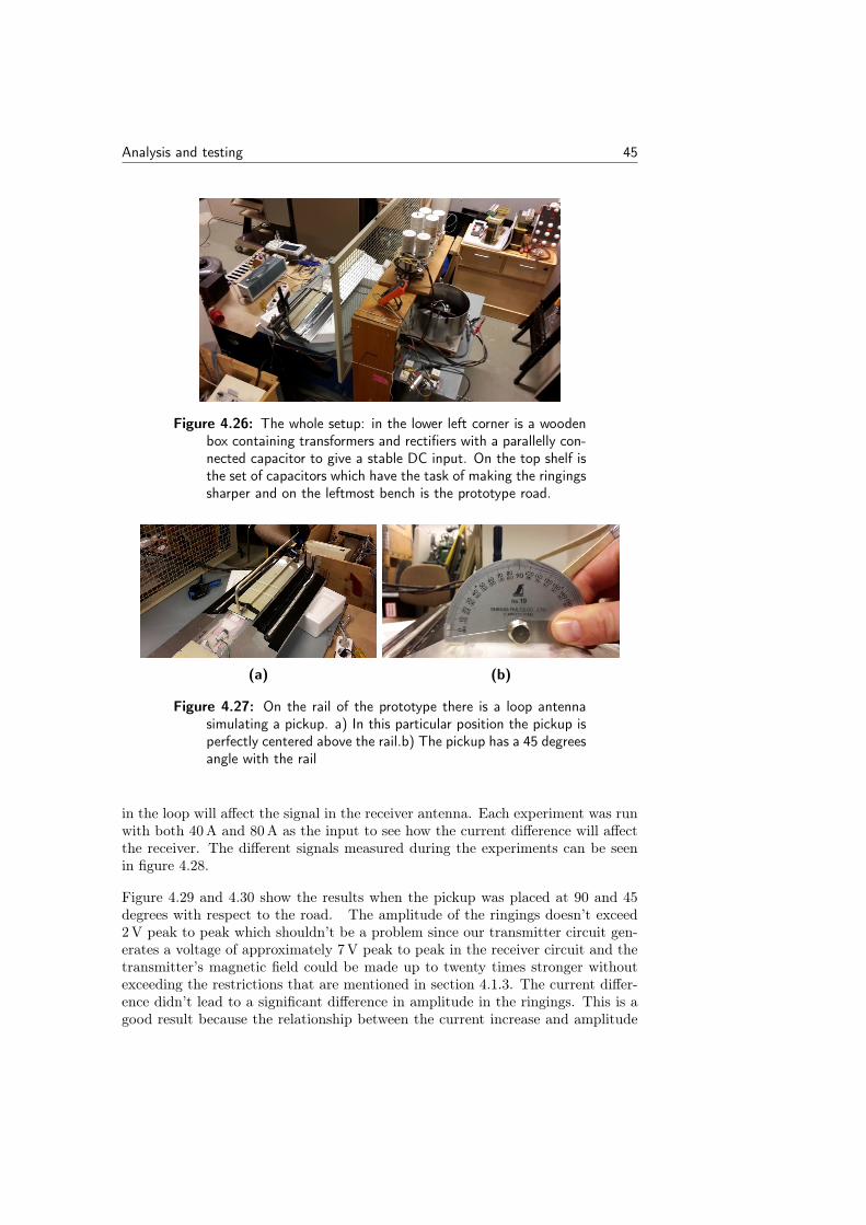
Analysis and testing 45
Figure 4.26: The whole setup: in the lower left corner is a woodenbox containing transformers and rectifiers with a parallelly con-nected capacitor to give a stable DC input. On the top shelf isthe set of capacitors which have the task of making the ringingssharper and on the leftmost bench is the prototype road.
(a) (b)
Figure 4.27: On the rail of the prototype there is a loop antennasimulating a pickup. a) In this particular position the pickup isperfectly centered above the rail.b) The pickup has a 45 degreesangle with the rail
in the loop will affect the signal in the receiver antenna. Each experiment was runwith both 40 A and 80 A as the input to see how the current difference will affectthe receiver. The different signals measured during the experiments can be seenin figure 4.28.
Figure 4.29 and 4.30 show the results when the pickup was placed at 90 and 45degrees with respect to the road. The amplitude of the ringings doesn’t exceed2 V peak to peak which shouldn’t be a problem since our transmitter circuit gen-erates a voltage of approximately 7 V peak to peak in the receiver circuit and thetransmitter’s magnetic field could be made up to twenty times stronger withoutexceeding the restrictions that are mentioned in section 4.1.3. The current differ-ence didn’t lead to a significant difference in amplitude in the ringings. This is agood result because the relationship between the current increase and amplitude
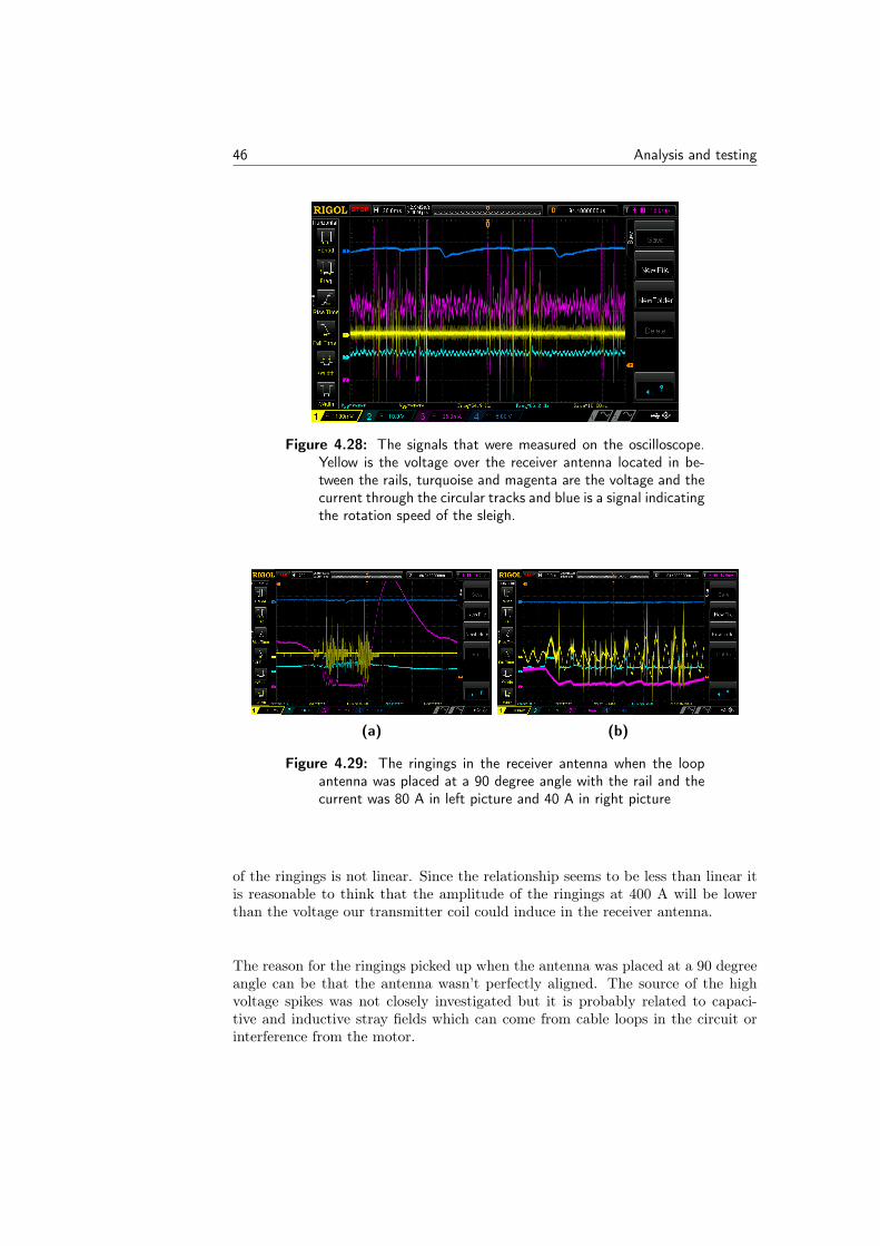
46 Analysis and testing
Figure 4.28: The signals that were measured on the oscilloscope.Yellow is the voltage over the receiver antenna located in be-tween the rails, turquoise and magenta are the voltage and thecurrent through the circular tracks and blue is a signal indicatingthe rotation speed of the sleigh.
(a) (b)
Figure 4.29: The ringings in the receiver antenna when the loopantenna was placed at a 90 degree angle with the rail and thecurrent was 80 A in left picture and 40 A in right picture
of the ringings is not linear. Since the relationship seems to be less than linear itis reasonable to think that the amplitude of the ringings at 400 A will be lowerthan the voltage our transmitter coil could induce in the receiver antenna.
The reason for the ringings picked up when the antenna was placed at a 90 degreeangle can be that the antenna wasn’t perfectly aligned. The source of the highvoltage spikes was not closely investigated but it is probably related to capaci-tive and inductive stray fields which can come from cable loops in the circuit orinterference from the motor.
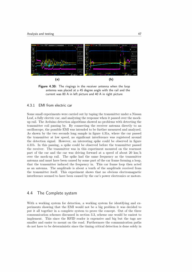
Analysis and testing 47
(a) (b)
Figure 4.30: The ringings in the receiver antenna when the loopantenna was placed at a 45 degree angle with the rail and thecurrent was 80 A in left picture and 40 A in right picture
4.3.1 EMI from electric car
Some small experiments were carried out by taping the transmitter under a NissanLeaf, a fully electric car, and analyzing the response when it passed over the mock-up rail. The Arduino detection algorithms showed no problems with detecting thetransmitter coil passing by. By connecting the receiver antenna directly to anoscilloscope, the possible EMI was intended to be further measured and analyzed.As shown by the two seconds long sample in figure 4.31a, where the car passedthe transmitter at low speed, no significant interference was registered aroundthe detection signal. However, an interesting spike could be observed in figure4.31b. In this passing, a spike could be observed before the transmitter passedthe receiver. The transmitter was in this experiment mounted on the rearmostpart of the car and the car was driving forward at a speed of about 20 km/hover the mock-up rail. The spike had the same frequency as the transmitterantenna and must have been caused by some part of the car frame forming a loop,that the transmitter induced the frequency in. This car frame loop then actedas an antenna. The amplitude is about a tenth of the amplitude received fromthe transmitter itself. This experiment shows that no obvious electromagneticinterference seemed to have been caused by the car’s power electronics or motors.
4.4 The Complete system
With a working system for detection, a working system for identifying and ex-periments showing that the EMI would not be a big problem it was decided toput it all together in a complete system to prove the concept. Out of the threecommunication schemes discussed in section 3.3, scheme one would be easiest toimplement. This since the RFID reader is expensive and big but the tags aresmaller and easier to mount on the road. Furthermore the communication pathsdo not have to be deterministic since the timing critical detection is done solely in
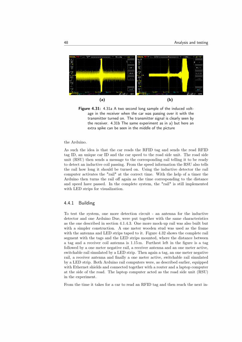
48 Analysis and testing
(a) (b)
Figure 4.31: 4.31a A two second long sample of the induced volt-age in the receiver when the car was passing over it with thetransmitter turned on. The transmitter signal is clearly seen bythe receiver. 4.31b The same experiment as in a) but here anextra spike can be seen in the middle of the picture
the Arduino.
As such the idea is that the car reads the RFID tag and sends the read RFIDtag ID, an unique car ID and the car speed to the road side unit. The road sideunit (RSU) then sends a message to the corresponding rail telling it to be readyto detect an inductive coil passing. From the speed information the RSU also tellsthe rail how long it should be turned on. Using the inductive detector the railcomputer activates the "rail" at the correct time. With the help of a timer theArduino then turns the rail off again as the time corresponding to the distanceand speed have passed. In the complete system, the "rail" is still implementedwith LED strips for visualization.
4.4.1 Building
To test the system, one more detection circuit - an antenna for the inductivedetector and one Arduino Due, were put together with the same characteristicsas the one described in section 4.1.4.3. One more mock-up rail was also built butwith a simpler construction. A one meter wooden stud was used as the framewith the antenna and LED strips taped to it. Figure 4.32 shows the complete railsegment with the tags and the LED strips mounted, where the distance betweena tag and a receiver coil antenna is 1.15 m. Furthest left in the figure is a tagfollowed by a one meter negative rail, a receiver antenna and an one meter active,switchable rail simulated by a LED strip. Then again a tag, an one meter negativerail, a receiver antenna and finally a one meter active, switchable rail simulatedby a LED strip. Both Arduino rail computers were, as described earlier, equippedwith Ethernet shields and connected together with a router and a laptop computerat the side of the road. The laptop computer acted as the road side unit (RSU)in the experiment.
From the time it takes for a car to read an RFID tag and then reach the next in-
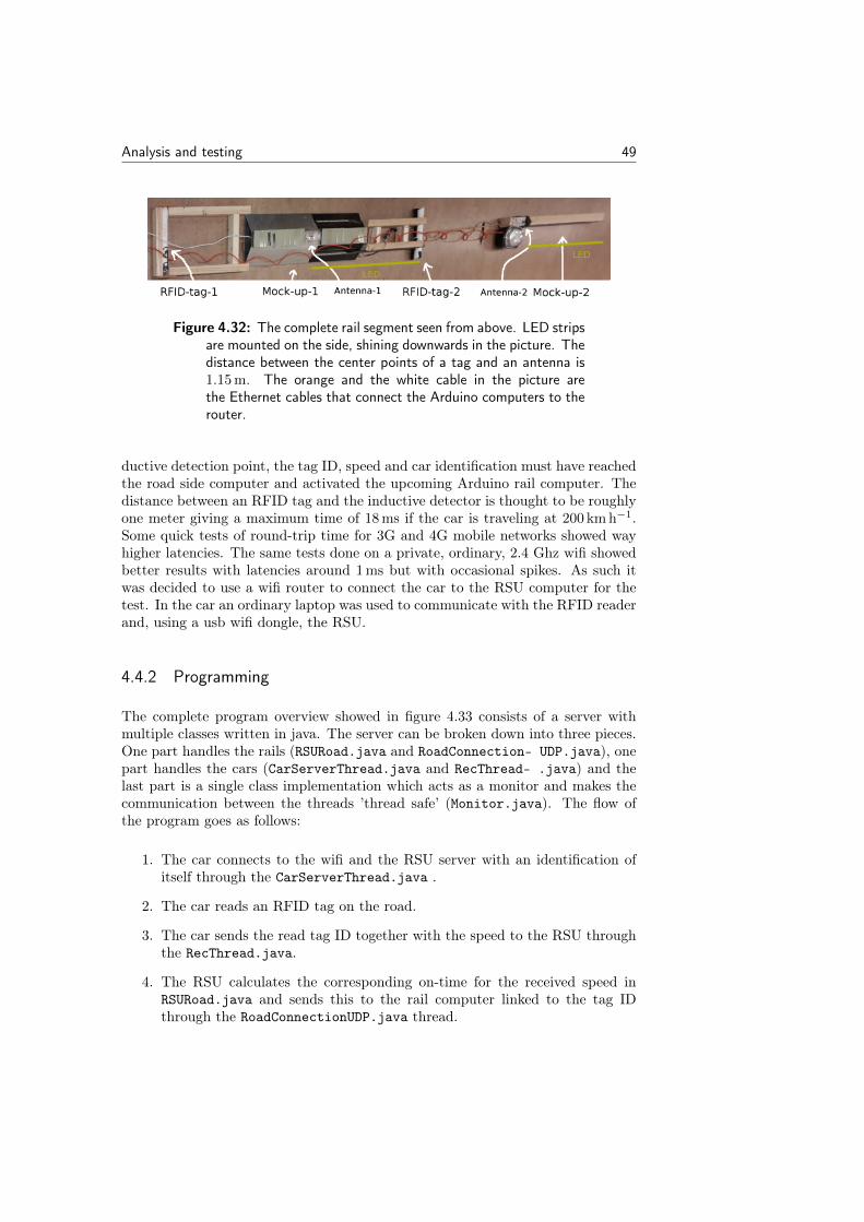
Analysis and testing 49
Figure 4.32: The complete rail segment seen from above. LED stripsare mounted on the side, shining downwards in the picture. Thedistance between the center points of a tag and an antenna is1.15 m. The orange and the white cable in the picture arethe Ethernet cables that connect the Arduino computers to therouter.
ductive detection point, the tag ID, speed and car identification must have reachedthe road side computer and activated the upcoming Arduino rail computer. Thedistance between an RFID tag and the inductive detector is thought to be roughlyone meter giving a maximum time of 18 ms if the car is traveling at 200 km h−1.Some quick tests of round-trip time for 3G and 4G mobile networks showed wayhigher latencies. The same tests done on a private, ordinary, 2.4 Ghz wifi showedbetter results with latencies around 1 ms but with occasional spikes. As such itwas decided to use a wifi router to connect the car to the RSU computer for thetest. In the car an ordinary laptop was used to communicate with the RFID readerand, using a usb wifi dongle, the RSU.
4.4.2 Programming
The complete program overview showed in figure 4.33 consists of a server withmultiple classes written in java. The server can be broken down into three pieces.One part handles the rails (RSURoad.java and RoadConnection- UDP.java), onepart handles the cars (CarServerThread.java and RecThread- .java) and thelast part is a single class implementation which acts as a monitor and makes thecommunication between the threads ’thread safe’ (Monitor.java). The flow ofthe program goes as follows:
1. The car connects to the wifi and the RSU server with an identification ofitself through the CarServerThread.java .
2. The car reads an RFID tag on the road.
3. The car sends the read tag ID together with the speed to the RSU throughthe RecThread.java.
4. The RSU calculates the corresponding on-time for the received speed inRSURoad.java and sends this to the rail computer linked to the tag IDthrough the RoadConnectionUDP.java thread.
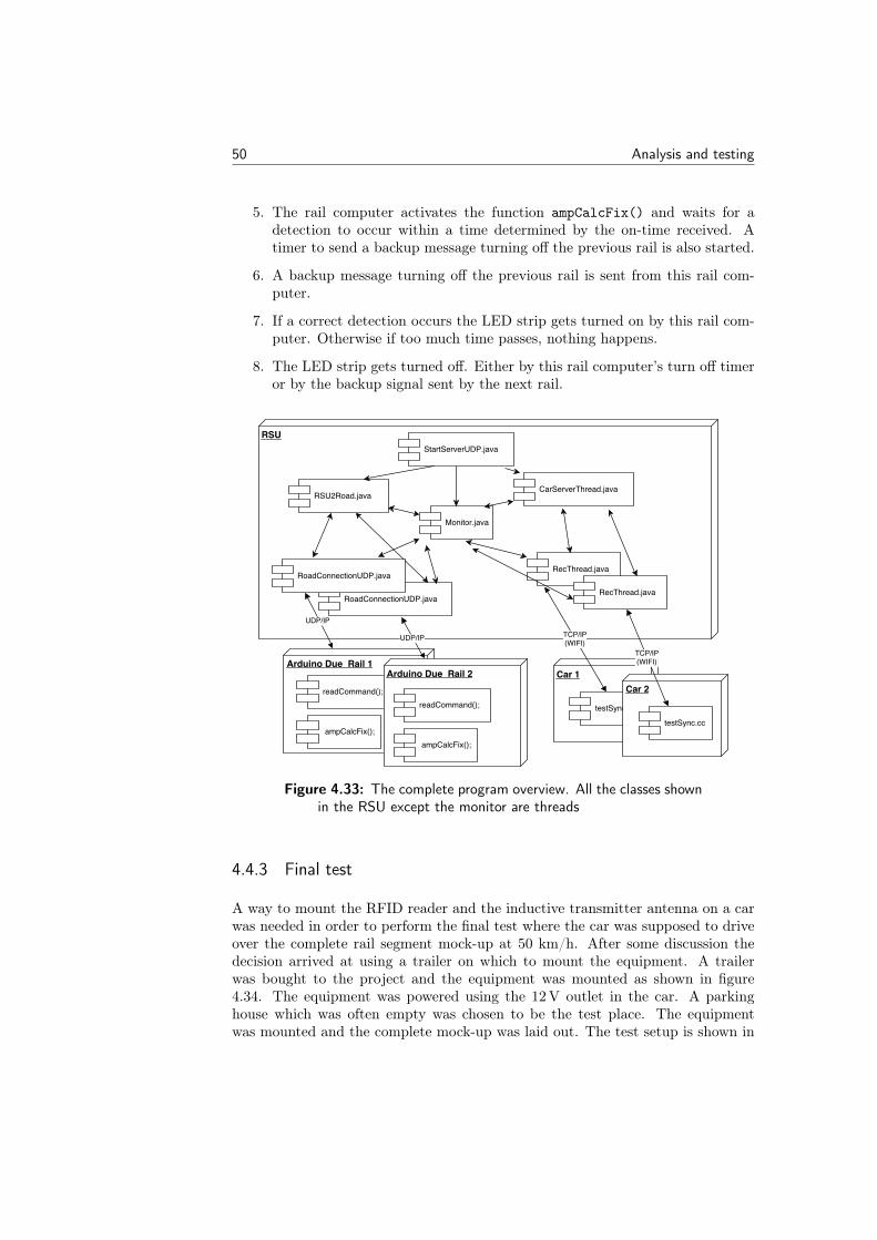
50 Analysis and testing
5. The rail computer activates the function ampCalcFix() and waits for adetection to occur within a time determined by the on-time received. Atimer to send a backup message turning off the previous rail is also started.
6. A backup message turning off the previous rail is sent from this rail com-puter.
7. If a correct detection occurs the LED strip gets turned on by this rail com-puter. Otherwise if too much time passes, nothing happens.
8. The LED strip gets turned off. Either by this rail computer’s turn off timeror by the backup signal sent by the next rail.
Figure 4.33: The complete program overview. All the classes shownin the RSU except the monitor are threads
4.4.3 Final test
A way to mount the RFID reader and the inductive transmitter antenna on a carwas needed in order to perform the final test where the car was supposed to driveover the complete rail segment mock-up at 50 km/h. After some discussion thedecision arrived at using a trailer on which to mount the equipment. A trailerwas bought to the project and the equipment was mounted as shown in figure4.34. The equipment was powered using the 12 V outlet in the car. A parkinghouse which was often empty was chosen to be the test place. The equipmentwas mounted and the complete mock-up was laid out. The test setup is shown in
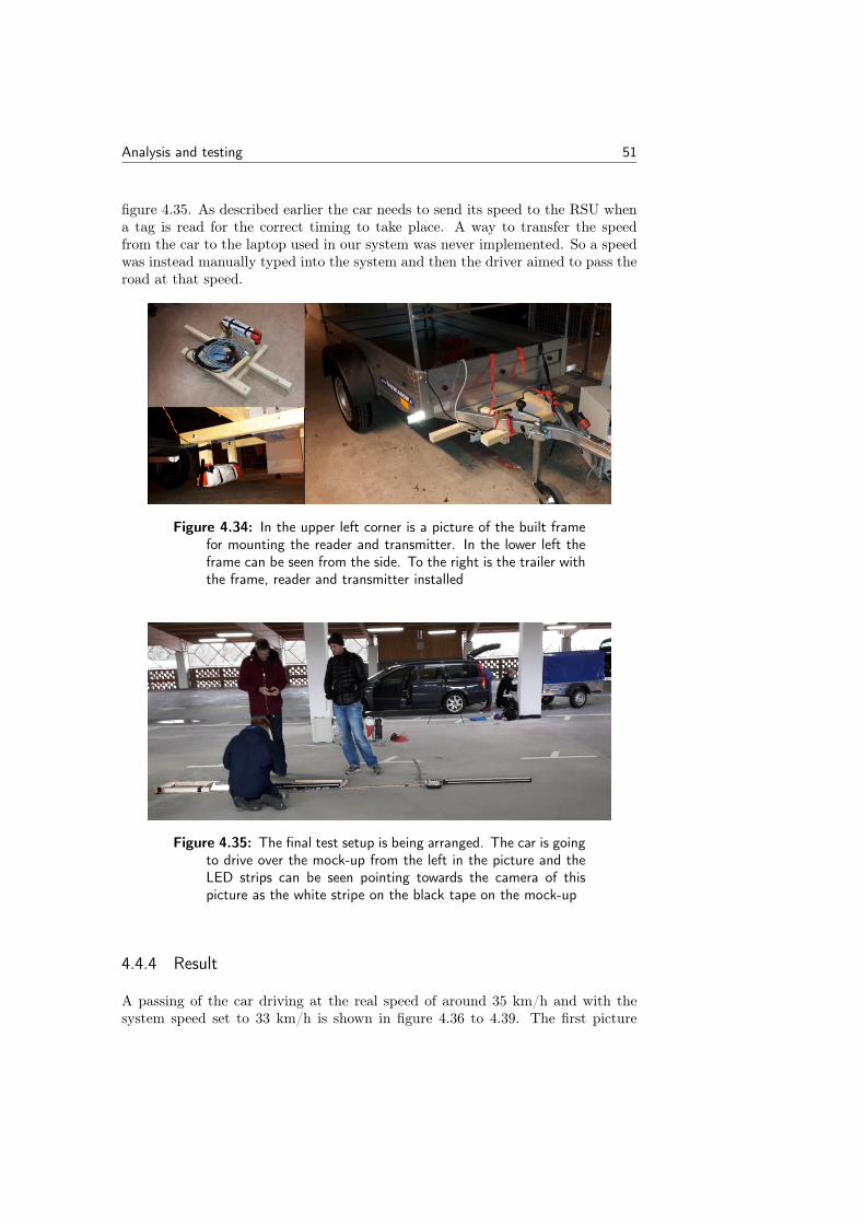
Analysis and testing 51
figure 4.35. As described earlier the car needs to send its speed to the RSU whena tag is read for the correct timing to take place. A way to transfer the speedfrom the car to the laptop used in our system was never implemented. So a speedwas instead manually typed into the system and then the driver aimed to pass theroad at that speed.
Figure 4.34: In the upper left corner is a picture of the built framefor mounting the reader and transmitter. In the lower left theframe can be seen from the side. To the right is the trailer withthe frame, reader and transmitter installed
Figure 4.35: The final test setup is being arranged. The car is goingto drive over the mock-up from the left in the picture and theLED strips can be seen pointing towards the camera of thispicture as the white stripe on the black tape on the mock-up
4.4.4 Result
A passing of the car driving at the real speed of around 35 km/h and with thesystem speed set to 33 km/h is shown in figure 4.36 to 4.39. The first picture
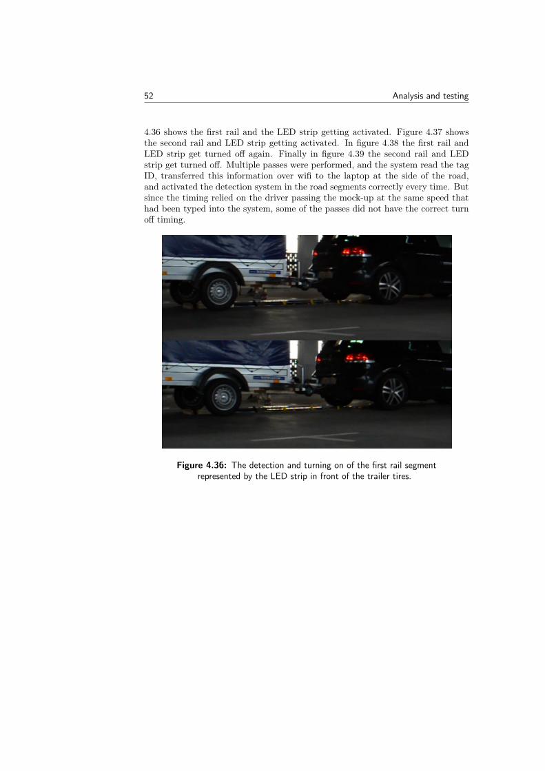
52 Analysis and testing
4.36 shows the first rail and the LED strip getting activated. Figure 4.37 showsthe second rail and LED strip getting activated. In figure 4.38 the first rail andLED strip get turned off again. Finally in figure 4.39 the second rail and LEDstrip get turned off. Multiple passes were performed, and the system read the tagID, transferred this information over wifi to the laptop at the side of the road,and activated the detection system in the road segments correctly every time. Butsince the timing relied on the driver passing the mock-up at the same speed thathad been typed into the system, some of the passes did not have the correct turnoff timing.
Figure 4.36: The detection and turning on of the first rail segmentrepresented by the LED strip in front of the trailer tires.
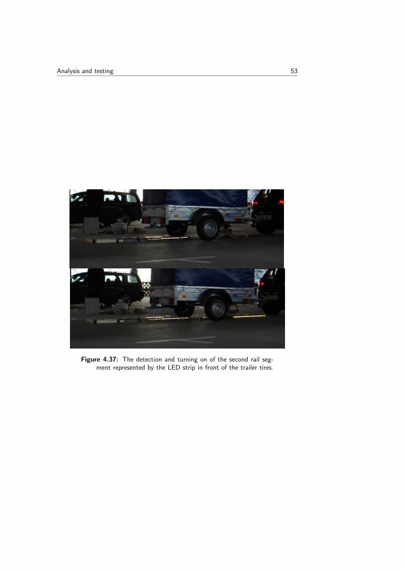
Analysis and testing 53
Figure 4.37: The detection and turning on of the second rail seg-ment represented by the LED strip in front of the trailer tires.
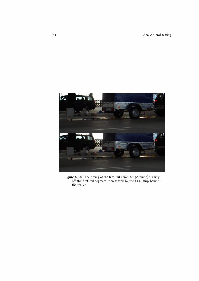
54 Analysis and testing
Figure 4.38: The timing of the first rail-computer (Arduino) turningoff the first rail segment represented by the LED strip behindthe trailer.
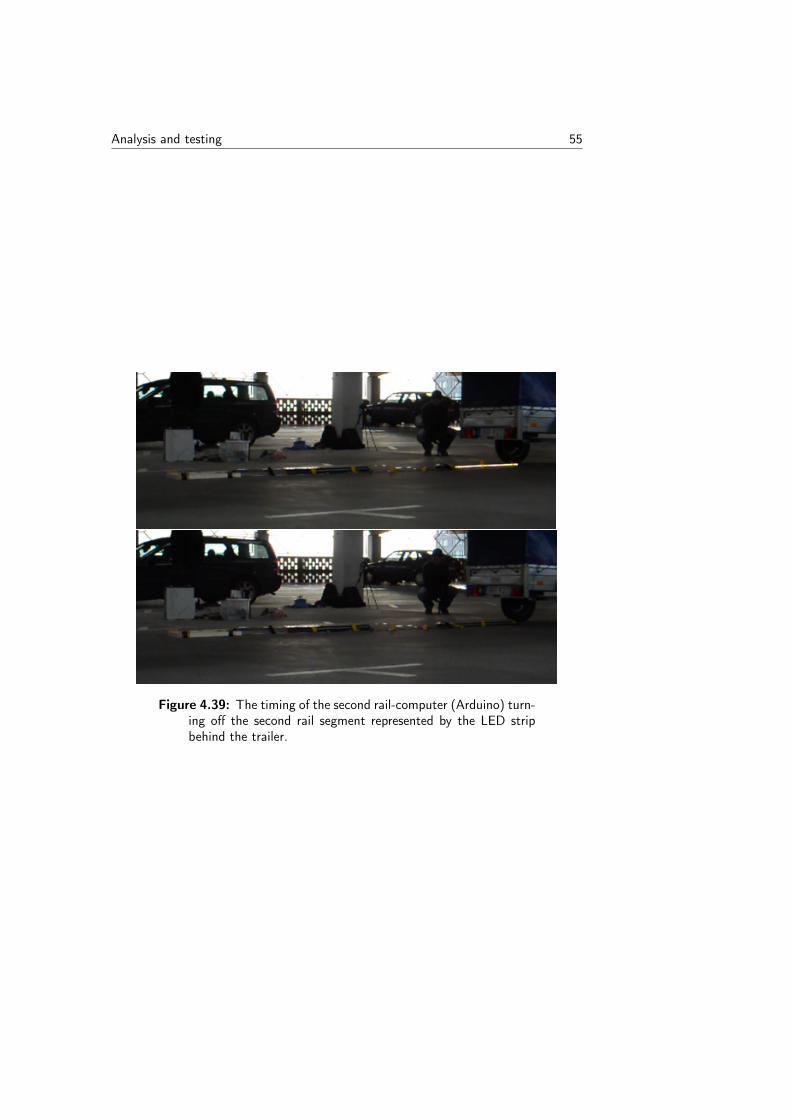
Analysis and testing 55
Figure 4.39: The timing of the second rail-computer (Arduino) turn-ing off the second rail segment represented by the LED stripbehind the trailer.

56 Analysis and testing
Chapter5Discussion and future work
The final experiment shows that the software and hardware designed in this thesisworks for detecting and identifying a moving vehicle with a little help. By help, itis meant here that the speed has to be manually given to the computer in the car.A possible way to get the speed information from the car into the laptop runningour program would be to use an open OBD reader1 with a suitable API. Thiswas however not investigated due to the limited time frame for the project. Theproblem of inputting the speed manually, as well as the too small test area andthe safety issues, since it was a place open to the public, restricted the posibilityof testing the complete setup at full speed. The fact that the RFID system isspecified to work at higher speeds, and that the earlier high speed test in section4.2 went well, still gives some confidence that the complete system would work athigher speeds as well. The final solution built is only a demonstrator for showinga proof of concept of our idea. As such the components and code are not in anyway optimized. Software and hardware optimization gives even greater confidencethat the system would be robust in tests at higher speeds.
A drawback of the design chosen to work with is the use of an RFID systemdeveloped by an external company. This system is built for trains and costs tensof thousands of euros each, making it a very expensive solution. What the pricewould be at the mass production of the scale road is not known and this could befurther investigated in the future.
The EMI experiments in section 4.3 point in the direction that the interferenceshould be possible to overcome and handle. But these experiments are made in amodel of how the real system might behave. How the real EMI environment willbe, with a 400 Ampere current flowing through the pickups, whose shape, behaviorand performance is unknown, is hard to model. It would be good to make furtherexperiments on the model with higher current values to see if the relation betweencurrent and interference can be better determined.
1OBD stands for "On-board diagnostics" and is a interface connection to a vehicle’sself-diagnostic and reporting capability that now is standardized in most cars and oftencan give real time information
57

58 Discussion and future work
To conclude it is deemed that all of the goals and aims set up for this thesis projectwere met with a satisfying outcome.

AppendixAProgram Code
A.1 Receiver Arduino Due: The rail road computer
1 #include <SPI.h>2 #include <SD.h>3 #include <Ethernet.h>45 #define DEBUG 167 //metal8 //#define RAIL6 1910 //tree11 #define RAIL7 11213 // Ethernet14 #ifdef RAIL715 byte mac[] = 16 0xDE , 0xAD , 0xBE , 0xEF , 0xFE , 0x0717 ;18 IPAddress ip(192, 168, 1, 167);19 #endif2021 #ifdef RAIL622 byte mac[] = 23 0xDE , 0xAD , 0xBE , 0xEF , 0xFE , 0x0624 ;25 IPAddress ip(192, 168, 1, 166);26 #endif2728 int port = 5217;29 IPAddress server (192, 168, 1, 33);30 IPAddress preRail (192, 168, 1, 166);3132 unsigned int localPort = 8888;
59
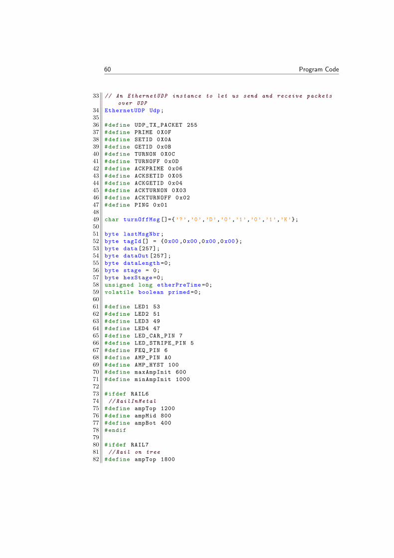
60 Program Code
33 // An EthernetUDP instance to let us send and receive packetsover UDP
34 EthernetUDP Udp;3536 #define UDP_TX_PACKET 25537 #define PRIME 0X0F38 #define SETID 0X0A39 #define GETID 0x0B40 #define TURNON 0X0C41 #define TURNOFF 0x0D42 #define ACKPRIME 0x0643 #define ACKSETID 0X0544 #define ACKGETID 0x0445 #define ACKTURNON 0X0346 #define ACKTURNOFF 0x0247 #define PING 0x014849 char turnOffMsg []=’?’,’0’,’D’,’0’,’1’,’0’,’1’,’K’;5051 byte lastMsgNbr;52 byte tagId[] = 0x00 ,0x00 ,0x00 ,0x00;53 byte data [257];54 byte dataOut [257];55 byte dataLength =0;56 byte stage = 0;57 byte hexStage =0;58 unsigned long etherPreTime =0;59 volatile boolean primed =0;6061 #define LED1 5362 #define LED2 5163 #define LED3 4964 #define LED4 4765 #define LED_CAR_PIN 766 #define LED_STRIPE_PIN 567 #define FEQ_PIN 668 #define AMP_PIN A069 #define AMP_HYST 10070 #define maxAmpInit 60071 #define minAmpInit 10007273 #ifdef RAIL674 // RailInMetal75 #define ampTop 120076 #define ampMid 80077 #define ampBot 40078 #endif7980 #ifdef RAIL781 //Rail on tree82 #define ampTop 1800
Program Code 61
83 #define ampMid 140084 #define ampBot 100085 #endif8687 volatile boolean testLedToggle;88 volatile int errorFlag;89 File root;90 const int chipSelectSD = 4;91 char filePrefix [] = "dr5a";92 char fileName [16];93 int fileNbrH =0;94 int fileNbrL =0;95 char fileEnd [] = ".txt";9697 volatile int pasTimerReset;98 volatile int sendTurnOff =0;99
100 unsigned long fF,fR,sF ,sR;101 boolean flagDetect = false; // Detect102 boolean flagCollectData=false;103 boolean flagCarDetect=false;104 volatile int stateCarPassed;105 volatile int lastState;106 volatile int nextInt;107 volatile int nextLow;108 #define BUFFER_SIZE 8 //8=8 samples mean value. compered at
68khz109 #define BUFFER_SIZE_BINDEX 3110 uint16_t buf[BUFFER_SIZE ];111112 int val;113 int maxAmp;114 int maxAmpHalf;115 int minAmp;116 int ampState;117 int oldAmpState;118 int ampDetectHigh =0;119 int ampDetectLow =0;120 int ampFailDetect =0;121 const int twoFactHighLow = 1; //high > 1^2 * low122 #define NBR_STATE 8123 unsigned long ampStateTime[NBR_STATE ];124 unsigned long ampDeltaLowTime;125 unsigned long ampDeltaHighTimeDiv;126 unsigned long ampStartTime;127 unsigned long ampNowTime;128 unsigned long ampLastTime;129 unsigned long ampDeltaRise;130 unsigned long ampDeltaFall;131 int ampCarDetect;132
62 Program Code
133 unsigned long timeTest =0;134 unsigned long timeTestS =0;135136 static __inline__ void digitalWriteDirect(int pin , boolean val
)137 //http :// forum.arduino.cc/index.php?topic =175617.0138 if(val) g_APinDescription[pin]. pPort -> PIO_SODR =
g_APinDescription[pin].ulPin;139 else g_APinDescription[pin]. pPort -> PIO_CODR =
g_APinDescription[pin].ulPin;140 141142143144 void InitsdLogger ()145 /*146 The circuit:147 * SD card attached to SPI bus as follows:148 ** MOSI - pin 11149 ** MISO - pin 12150 ** CLK - pin 13151 ** CS - pin 4152 */153 // see if the card is present and can be initialized:154 if (!SD.begin(chipSelectSD)) 155 errorFlag =1;156 digitalWriteDirect(LED1 , LOW);157 digitalWriteDirect(LED4 , HIGH);158 // don’t do anything more:159 return;160 161 fileNbrL =0;162 fileNbrH =0;163 sprintf(fileName ,"%s%d%s", filePrefix , fileNbrL , fileEnd);164 while(SD.exists(fileName))165 digitalWriteDirect(LED3 , HIGH);166 fileNbrL ++;167 if(fileNbrL >7)168 fileNbrH +=10;169 fileNbrL =0;170 171 int i =fileNbrL+fileNbrH;172 sprintf(fileName ,"%s%d%s", filePrefix , (i), fileEnd);173174 175 digitalWriteDirect(LED3 , LOW);176 177 void ledCount(int count)178 switch (count )179 180 case 0:
Program Code 63
181 digitalWriteDirect(LED4 , LOW);182 digitalWriteDirect(LED3 , LOW);183 digitalWriteDirect(LED2 , LOW);184 break;185 case 1:186 digitalWriteDirect(LED4 , HIGH);187 digitalWriteDirect(LED3 , LOW);188 digitalWriteDirect(LED2 , LOW);189 break;190 case 2:191 digitalWriteDirect(LED4 , LOW);192 digitalWriteDirect(LED3 , HIGH);193 digitalWriteDirect(LED2 , LOW);194 break;195 case 3:196 digitalWriteDirect(LED4 , HIGH);197 digitalWriteDirect(LED3 , HIGH);198 digitalWriteDirect(LED2 , LOW);199 break;200 case 4:201 digitalWriteDirect(LED4 , LOW);202 digitalWriteDirect(LED3 , LOW);203 digitalWriteDirect(LED2 , HIGH);204 break;205 case 5:206 digitalWriteDirect(LED4 , HIGH);207 digitalWriteDirect(LED3 , LOW);208 digitalWriteDirect(LED2 , HIGH);209 break;210 case 6:211 digitalWriteDirect(LED4 , LOW);212 digitalWriteDirect(LED3 , HIGH);213 digitalWriteDirect(LED2 , HIGH);214 break;215 case 7:216 digitalWriteDirect(LED4 , HIGH);217 digitalWriteDirect(LED3 , HIGH);218 digitalWriteDirect(LED2 , HIGH);219 break;220 221 222223 void InitTimerFast(Tc *tc, uint32_t channel , IRQn_Type irq ,
uint32_t time100us)224 //http :// ko7m.blogspot.se /2015/01/ arduino -due -timers -part -1.
html225 226 pmc_set_writeprotect(false);227 pmc_enable_periph_clk(irq);228 // clock2 is /8 and clock4 is /128229 TC_Configure(tc , channel , TC_CMR_WAVE | TC_CMR_WAVSEL_UP_RC
64 Program Code
| TC_CMR_TCCLKS_TIMER_CLOCK3 );230 uint32_t rc = 263 * time100us; // VARIANT_MCK / 32 / 10000 *
time100us;231 TC_SetRC(tc , channel , rc);232 // TC_Start(tc , channel);233 tc ->TC_CHANNEL[channel ]. TC_IER= TC_IER_CPCS;234 tc ->TC_CHANNEL[channel ]. TC_IDR =~( TC_IER_CPCS);235 NVIC_EnableIRQ(irq);236 237 void InitTimerSlow(Tc *tc, uint32_t channel , IRQn_Type irq ,
uint32_t timeMilli)238 //http :// ko7m.blogspot.se /2015/01/ arduino -due -timers -part -1.
html239 240 pmc_set_writeprotect(false);241 pmc_enable_periph_clk(irq);242243 TC_Configure(tc , channel , TC_CMR_WAVE | TC_CMR_WAVSEL_UP_RC
| TC_CMR_TCCLKS_TIMER_CLOCK5 );244 uint32_t rc = 32 * timeMilli; //32000 / 1000 * timeMilli;245 TC_SetRC(tc , channel , rc);246 // TC_Start(tc , channel);247 tc ->TC_CHANNEL[channel ]. TC_IER= TC_IER_CPCS;248 tc ->TC_CHANNEL[channel ]. TC_IDR =~( TC_IER_CPCS);249 NVIC_EnableIRQ(irq);250 251 void AdcInit ()252 // http :// nicecircuits.com/playing -with -analog -to-digital -
converter -on-arduino -due/253 254 // Setup all registers255 pmc_enable_periph_clk(ID_ADC); // To use peripheral , we must
enable clock distributon to it256 adc_init(ADC , SystemCoreClock , ADC_FREQ_MAX ,
ADC_STARTUP_FAST); // initialize ADC_FREQ_MIN =20 ksampleADC_FREQ_MAX =544 ksample
257 adc_disable_interrupt(ADC , 0xFFFFFFFF);258 adc_set_resolution(ADC , ADC_10_BITS);259 adc_configure_power_save(ADC , 0, 0); // Disable sleep260 adc_configure_timing(ADC , 0, ADC_SETTLING_TIME_3 , 1); // Set
timings - standard values261 adc_set_bias_current(ADC , 1); // Bias current - maximum
performance over current consumption262 adc_stop_sequencer(ADC); // not using it263 adc_disable_tag(ADC); // it has to do with sequencer , not
using it264 adc_disable_ts(ADC); // deisable temperature sensor265 adc_disable_channel_differential_input(ADC , ADC_CHANNEL_7);
//pin A0266 adc_configure_trigger(ADC , ADC_TRIG_SW , 1); // triggering
from software , freerunning mode
Program Code 65
267 adc_disable_all_channel(ADC);268 adc_enable_channel(ADC , ADC_CHANNEL_7); // just one channel
enabled269270 // configure Peripheral DMA271272 273274 // the setup routine runs once when you press reset:275 void setup() 276 sendTurnOff =0;277 errorFlag =0;278 pinMode(FEQ_PIN ,INPUT);279 pinMode(AMP_PIN ,INPUT);280 pinMode(LED_CAR_PIN ,OUTPUT);281 pinMode(LED_STRIPE_PIN ,OUTPUT);282 // pinMode (13, OUTPUT);283284 pinMode (39, OUTPUT);285 digitalWrite (39,LOW);286 testLedToggle=LOW;287288289290 InitTimerSlow(TC2 ,1, TC7_IRQn , 500); // used for TimerReset
. last variabel: time [ms]291 InitTimerFast(TC2 , 2, TC8_IRQn , 1800); // used for
TimerNoFreq. last variabel: time [ms/10]292 pasTimerReset =0;293294295 AdcInit ();296 adc_start(ADC);297 pinMode(LED1 ,OUTPUT);298 pinMode(LED2 ,OUTPUT);299 pinMode(LED3 ,OUTPUT);300 pinMode(LED4 ,OUTPUT);301 digitalWrite(LED_CAR_PIN , LOW);302 digitalWrite(LED_STRIPE_PIN , LOW);303 clearFreqState ();304 clearAmpState ();305 digitalWriteDirect(LED1 , HIGH);306307 #ifdef DEBUG308 Serial.begin (115200);309 #endif310311 delay (100);312 InitsdLogger ();313 PDC_ADC ->PERIPH_RPR = (uint32_t) buf; // address of buffer314 PDC_ADC ->PERIPH_RCR = BUFFER_SIZE;
66 Program Code
315 PDC_ADC ->PERIPH_PTCR = PERIPH_PTCR_RXTEN; // enable receive316 delay (1000);317 // start the Ethernet connection:318 Ethernet.begin(mac , ip);319 Udp.begin(localPort);320 lastMsgNbr= 0;321322 323324 void clearFreqState ()325 lastState =-1;326 stateCarPassed =-1;327 nextInt =0;328 nextLow =0;329 fR=fF=sR=sF=0;330 331332 void clearAmpState ()333 minAmp=minAmpInit;334 maxAmp=maxAmpInit;335 ampState =0;336 oldAmpState =0;337 ampDetectHigh =0;338 ampDetectLow =0;339 ampFailDetect =0;340 digitalWriteDirect(LED4 , LOW);341 digitalWriteDirect(LED3 , LOW);342 digitalWriteDirect(LED2 , LOW);343 // digitalWriteDirect(LED1 , LOW);344 for(int i=0; i < NBR_STATE; i++)345 ampStateTime[i]=0;346 347 ampDeltaLowTime =0;348 ampDeltaHighTimeDiv =0;349 ampStartTime =0;350 ampNowTime =0;351 ampCarDetect =0;352 // digitalWriteDirect(LED_CAR_PIN , LOW);353 // digitalWriteDirect(LED_STRIPE_PIN , LOW);354 ampDeltaRise =0;355 ampDeltaFall =0;356 ledCount(fileNbrL);357358 359360 void startTimerReset ()361 // Start and reset timmer to reset statemachine when no
change for long362 //uses timmer TC2 chanel 1363 TC2 ->TC_CHANNEL [1]. TC_CCR &= ~TC_CCR_CLKDIS;364 TC2 ->TC_CHANNEL [1]. TC_CCR |=
Program Code 67
365 TC_CCR_CLKEN | // enables the clock if CLKDIS is not 1366 TC_CCR_SWTRG; // the counter is reset and the clock is
started367 TC_GetStatus(TC2 , 1);368 digitalWriteDirect(LED1 , LOW);369370 371372 void startTurnOffTimer ()373 //uses timmer TC2 chanel 2374 TC2 ->TC_CHANNEL [2]. TC_CCR &= ~TC_CCR_CLKDIS;375 TC2 ->TC_CHANNEL [2]. TC_CCR |=376 TC_CCR_CLKEN | // enables the clock if CLKDIS is not 1377 TC_CCR_SWTRG; // the counter is reset and the clock is
started378 TC_GetStatus(TC2 , 2);379 380 void startTimerSendTurnOffBack ()381 //uses timmer TC2 chanel 0382 TC2 ->TC_CHANNEL [0]. TC_CCR &= ~TC_CCR_CLKDIS;383 TC2 ->TC_CHANNEL [0]. TC_CCR |=384 TC_CCR_CLKEN | // enables the clock if CLKDIS is not 1385 TC_CCR_SWTRG; // the counter is reset and the clock is
started386 TC_GetStatus(TC2 , 0);387 388389 // the loop routine runs over and over again forever:390 void loop() 391 ethernet ();392393 if(primed) // start recive if primed394 if(( adc_get_status(ADC) & ADC_ISR_ENDRX) != 0) // waiting
for buffer to fill upp (544 ksample /16=18 khz395 ampCalcFix ();396 PDC_ADC ->PERIPH_RPR = (uint32_t) buf; // address of
buffer397 PDC_ADC ->PERIPH_RCR = BUFFER_SIZE;398 PDC_ADC ->PERIPH_PTCR = PERIPH_PTCR_RXTEN; // enable
receive399 400 401 // ampPrint ();402 if(pasTimerReset)403 clearAmpState ();404 pasTimerReset =0;405 primed =0;406 407 readCommand ();408 if(sendTurnOff)409 sendTurnOff =0;
68 Program Code
410 sendMsg(preRail ,turnOffMsg);411 #ifdef DEBUG412 Serial.print("TurnOff sent");413 #endif414 415 416 void ethernet ()417 char packetBuffer[UDP_TX_PACKET ]=;418 noInterrupts ();419 int packetSize = Udp.parsePacket ();420 interrupts ();421 int startIndex =0;422 if (packetSize)423 424 IPAddress remote = Udp.remoteIP ();425 Udp.read(packetBuffer , UDP_TX_PACKET);426 char checksum = 0;427 for(int i=0; i < packetSize; i++)428 checksum ^= packetBuffer[i];429 if(packetBuffer[i]==’?’)430 startIndex=i;431 #ifdef DEBUG432 Serial.print("StartIndex: ");433 Serial.println(startIndex);434 #endif435 436 437 if(packetBuffer [0]==’?’)438 if(! checksum)439 data [0] = hexDecode(packetBuffer [1]) <<4; // *16440 data [0] += hexDecode(packetBuffer [2]);441 if((data [0]== lastMsgNbr) && ((data [0] & 0xF0)!= 0))442 #ifdef DEBUG443 Serial.print("same: ");444 #endif445 else446 data [1] = hexDecode(packetBuffer [3]) <<4; // *16447 data [1] += hexDecode(packetBuffer [4]);448 for(int i = 0; i < (data[1]<<1);i+=2)449 #ifdef DEBUG450 Serial.print("index:");451 Serial.println(i);452 #endif453 data [2+(i>>1)] = hexDecode(packetBuffer [5+i])
<<4; // *16454 data [2+(i>>1)] += hexDecode(packetBuffer [6+i]);455 456 if(packetBuffer [(4+ data [1]) <<1])457 #ifdef DEBUG458 Serial.println("correct!");459 #endif
Program Code 69
460 461 instruction ();462 lastMsgNbr=packetBuffer [1];463 464 #ifdef DEBUG465 Serial.println("awnser");466 #endif467 Udp.beginPacket(Udp.remoteIP (), Udp.remotePort ());468 Udp.write(’!’);469 checksum=’!’;470 for(int i = 0; i < dataOut [1] + 2; i++)471 472 #ifdef DEBUG473 Serial.print((char)hexEncode(dataOut[i] >>4)); //
/16474 Serial.print((char)hexEncode(dataOut[i] & 0xF)); //
%16475 #endif476 checksum ^= hexEncode(dataOut[i] >>4);477 checksum ^= hexEncode(dataOut[i] & 0x0F);478 Udp.write(hexEncode(dataOut[i] >>4)); // /16479 Udp.write(hexEncode(dataOut[i] & 0x0F)); // %16480 481482 Udp.write(checksum);483 Udp.endPacket ();484 // lastInstruction = millis ();485 #ifdef DEBUG486 Serial.println("done");487 #endif488 489 else if(packetBuffer [0]==’!’)490 //TODO send again if this is not recived after sendMsg.491 #ifdef DEBUG492 Serial.println("gotAwnser");493 #endif494 495 496497498 499 byte hexDecode(byte c)500 501 if(c >= ’0’ && c <= ’9’)502 503 return c - ’0’;504 505 else if(c >= ’a’ && c <= ’f’)506 507 return c - ’a’ + 10;508
70 Program Code
509 else if(c >= ’A’ && c <= ’F’)510 511 return c - ’A’ + 10;512 513 else514 515 return 0;516 517 518519 byte hexEncode(byte n, boolean cap)520 521 if(n >= 0 && n <= 9)522 523 return n + ’0’;524 525 else if(n >= 10 && n <= 15)526 527 if(cap)528 529 return n - 10 + ’A’;530 531 else532 533 return n - 10 + ’a’;534 535 536 else537 538 return ’0’;539 540 541542 byte hexEncode(byte n)543 544 return hexEncode(n, true);545 546 void instruction ()547 #ifdef DEBUG548549 Serial.print("msg recived. lenght");550 Serial.println(data [1]);551 for(int i = 0; i < data [1] + 2; i++)552 553 Serial.print((char)hexEncode(data[i] >>4)); // /16554 Serial.print((char)hexEncode(data[i] & 0xF)); // %16555 556 Serial.println("\n msg end");557 #endif558559 if(data [0]== SETID)
Program Code 71
560 if(data [1]==4)561 #ifdef DEBUG562 Serial.println("setId start");563 #endif564 for(int i=0;i<data [1]; i++)565 tagId[i]=data[i+2];566 #ifdef DEBUG567 Serial.println(tagId[i]);568 #endif569 570 dataOut [0]= ACKSETID;571 dataOut [1]=1;572 dataOut [2]= PRIME;573 #ifdef DEBUG574 Serial.println("setId done");575 #endif576 577 578 if(data [0]== GETID)579 dataOut [0]= ACKGETID;580 dataOut [1]=4;581 for(int i=0;i<dataOut [1]; i++)582 dataOut[i+2]= tagId[i];583 #ifdef DEBUG584 Serial.println(dataOut[i+2]);585 #endif586 587 #ifdef DEBUG588 Serial.println("getId done");589 #endif590591 592 if(data [0]== PRIME)593 primed =1;594 dataOut [0]= ACKPRIME;595 #ifdef DEBUG596 Serial.println("priming");597 #endif598 if(data [1]==2)599 int onTime = ((data [2] & 0XFF) << 8) + ((data [3])
& 0XFF);600 #ifdef DEBUG601 Serial.println(onTime);602 #endif603 InitTimerFast(TC2 , 2, TC8_IRQn , onTime); // used
for TimerTurnoff. last variabel: time [ms/10]604 onTime=onTime >>3;605 InitTimerSlow(TC2 ,1, TC7_IRQn , onTime); // used
for TimerReset. last variabel: time [ms] >>3makes wait time: 10/8=1. times longer
606 startTimerReset ();
72 Program Code
607 dataOut [1]=1;608 dataOut [2]=0;609 InitTimerFast(TC2 , 0, TC6_IRQn , onTime); // used
for TimerTurnoff. last variabel: time [ms/10]610 #ifdef DEBUG611 Serial.println("time to send turnoff");612 Serial.println(onTime);613 #endif614 615 616 if(data [0]== TURNON)617 #ifdef DEBUG618 Serial.println("turning on");619 #endif620 digitalWriteDirect(LED_CAR_PIN ,HIGH);621 digitalWriteDirect( LED_STRIPE_PIN ,HIGH);622 dataOut [0]= ACKTURNON;623 dataOut [1]=1;624 dataOut [2]= TURNON;625 626 if(data [0]== TURNOFF)627 #ifdef DEBUG628 Serial.println("turning off");629 #endif630 dataOut [0]= ACKTURNOFF;631 dataOut [1]=0 x01;632 dataOut [2]= TURNOFF;633 digitalWriteDirect(LED_CAR_PIN ,LOW);634 digitalWriteDirect( LED_STRIPE_PIN ,LOW);635 636637638 639640 void sendMsg(IPAddress rec , char msg [])641 Udp.beginPacket(rec , localPort);642 Udp.write(msg ,8);643 Udp.endPacket ();644 645646 void readCommand ()647 if (Serial.available () > 0) 648 int command= Serial.parseInt ();649 if(command ==0)650 Serial.println("0=help , 1=list , 2= readCurentFile , 3=
chose file to read , 4= eraseAll");651 else if(command ==1)652 char tempName [16];653 Serial.println("------print list -------");654 int i = 0;655 int ii= 0;
Program Code 73
656 sprintf(tempName ,"%s%d%s", filePrefix , i, fileEnd);657 while(SD.exists(tempName))658 Serial.print(" ");659 Serial.println(tempName);660 i++;661 if(i>7)662 ii+=10;663 664 int j= ii+i;665 sprintf(tempName ,"%s%d%s", filePrefix , j, fileEnd);666 667 Serial.println("------Done!-------\n\n");668 else if(command ==2)669 File tempFile = SD.open(fileName);670 if (tempFile) 671 Serial.println("----------------------");672 Serial.println(fileName);673674 // read from the file until there ’s nothing else in it
:675 while (tempFile.available ()) 676 Serial.write(tempFile.read());677 678 // close the file:679 tempFile.close();680 Serial.println("----------------------\n\n");681 else 682 // if the file didn’t open , print an error:683 Serial.println("error opening file");684 685686 else if(command ==3)687 char tempName [16];688 Serial.println("Read file number:");689 while(Serial.available ()==0)690 691 int i = Serial.parseInt ();692 if(i==0)693 return;694 695 sprintf(tempName ,"%s%d%s", filePrefix , i, fileEnd);696 if(SD.exists(tempName))697 File tempFile = SD.open(tempName);698 if (tempFile) 699 Serial.println("----------------------");700 Serial.println(tempName);701702 // read from the file until there ’s nothing else in
it:703 while (tempFile.available ()) 704
74 Program Code
705 Serial.write(tempFile.read());706 707 // close the file:708 tempFile.close();709 Serial.println("----------------------\n\n");710 else 711 // if the file didn’t open , print an error:712 Serial.println("error opening file");713 714 else715 Serial.println("No file with that name exists");716 717718719 else if(command ==4)720 char tempName [16];721 Serial.println("remove All? (y/n)");722 while(Serial.available ()==0)723 724 int temp = Serial.read();725 Serial.println(temp);726 if(temp != ’y’)727 Serial.println("Aborted");728 return;729 int i = 0;730 int ii= 0;731 sprintf(tempName ,"%s%d%s", filePrefix , i, fileEnd);732 while(SD.exists(tempName))733 SD.remove(tempName);734 i++;735 if(i>7)736 ii+=10;737 738 int j= ii+i;739 sprintf(tempName ,"%s%d%s", filePrefix , j, fileEnd);740 741 Serial.println("Done removing");742 743 744 745746747748 boolean sdLog(char dataString [])749 // open the file. note that only one file can be open at a
time ,750 // so you have to close this one before opening another.751 File dataFile = SD.open(fileName , FILE_WRITE);752753 // if the file is available , write to it:754 if (dataFile)
Program Code 75
755 dataFile.println(dataString);756 dataFile.close();757 return 1;758 759 // if the file isn’t open , pop up an error:760 else 761 digitalWriteDirect(LED1 , LOW);762 return 0;763 764765 766 void ampCalcFix ()767 val =0;768 for (int i=0; i<BUFFER_SIZE; i++)769 val+=buf[i];770 771 val=val >>BUFFER_SIZE_BINDEX;772 if(val <minAmp)773 minAmp=val;774 775 if(maxAmp <val)776 maxAmp=val;777 778 // /779 if(( ampState ==0)&& (ampMid <val))780 #ifdef DEBUG781 Serial.println("StartDetect");782 // Serial.println(startIndex);783 #endif784 maxAmp=val;785 ampStartTime= micros ();786 ampStateTime[ampState ]= ampStartTime;787 startTimerReset ();788 ampState =1;789 minAmp=val; //to find new minAmp790 digitalWriteDirect(LED4 , HIGH);791 digitalWriteDirect(LED3 , LOW);792 digitalWriteDirect(LED2 , LOW);793 // /794 else if(( ampState ==1)&& (ampTop <val))795 ampNowTime = micros ();796 ampStateTime[ampState] = ampNowTime;797 ampState =2;798 ampDeltaRise = ampNowTime -ampStartTime;799 digitalWriteDirect(LED4 , LOW);800 digitalWriteDirect(LED3 , HIGH);801 // digitalWriteDirect(LED2 , LOW);802 // ^803 else if(ampState ==2 && (val+AMP_HYST) < maxAmp)804 ampDetectHigh=maxAmp;805 maxAmpHalf= maxAmp >>2;
76 Program Code
806 ampStateTime[ampState] = micros ();807 ampState =3;808 digitalWriteDirect(LED4 , HIGH);809 // digitalWriteDirect(LED3 , HIGH);810 // digitalWriteDirect(LED2 , LOW);811 // \812 else if( ampState ==3 && (val <ampMid))813 ampNowTime= micros ();814 ampLastTime=ampNowTime;815 ampStateTime [3] = ampNowTime;816 ampDeltaHighTimeDiv = (ampNowTime -ampStartTime);//>>
twoFactHighLow;817 // FailDetect 1 To short High!818 if(ampDeltaHighTimeDiv <100)819 ampFailDetect =1;820 ampState =20;821 return;822 823 ampState =4;824 // ampDeltaHighTimeDiv=ampDeltaHighTimeDiv *10; //fix825 digitalWriteDirect(LED4 , LOW);826 digitalWriteDirect(LED3 , LOW);827 digitalWriteDirect(LED2 , HIGH);828 // \+829 // else if(( ampState ==3 || ampState ==4) && val <
maxAmpHalf)830 // ampStateTime [4] = micros ();831 // ampState =5;832 // digitalWriteDirect(LED4 , HIGH);833 // // digitalWriteDirect(LED3 , LOW);834 // // digitalWriteDirect(LED2 , HIGH);835 // // v836 else if(( ampState ==4)&& (val <ampBot))837 ampNowTime= micros ();838 ampStateTime[ampState] = ampNowTime;839 ampDeltaFall = ampNowTime -ampLastTime;840 ampState =5;841 digitalWriteDirect(LED4 , HIGH);842 digitalWriteDirect(LED3 , LOW);843 // digitalWriteDirect(LED2 , HIGH);844 // Faildetect 2 to long DeltaFall845 if(ampDeltaRise < ampDeltaFall)846 ampState =20;847 ampFailDetect =2;848 849850 else if(ampState ==5 && (ampMid <val))851 ampNowTime=micros ();852 ampStateTime[ampState ]= ampNowTime;853 ampDeltaLowTime = (ampNowTime -ampLastTime);854 ampDetectLow=minAmp;
Program Code 77
855 ampState =6;856857 digitalWriteDirect(LED4 , LOW);858 digitalWriteDirect(LED3 , HIGH);859 else if(ampState ==5)860 // Faildetect 3 to long low861 unsigned long currentMillis = micros ();862 if (( currentMillis - ampNowTime) >=
ampDeltaHighTimeDiv)863 ampState =20;864 ampFailDetect =3;865 ampStateTime[ampState ]= currentMillis;866 867 // /868 else if(ampState ==6 && ampTop <val)869 // Correct Starting rail.870 if(ampDeltaLowTime < ampDeltaHighTimeDiv)871 digitalWriteDirect(LED_CAR_PIN , HIGH);872 digitalWriteDirect(LED_STRIPE_PIN , HIGH);873 ampCarDetect =1;874 startTurnOffTimer ();875 startTimerSendTurnOffBack ();876 #ifdef DEBUG877 Serial.println("detect");878 // Serial.println(startIndex);879 #endif880 881 ampState =7;882 digitalWriteDirect(LED4 , HIGH);883 ampStateTime [6]= micros ();884 // digitalWriteDirect(LED3 , HIGH);885 // digitalWriteDirect(LED2 , HIGH);886887 else if(( ampState ==7) && (val <ampBot))888 ampStateTime[ampState] = micros ();889 ampState =0;890 primed =0;891 // digitalWriteDirect(LED_STRIPE_PIN , LOW);892 // digitalWriteDirect(LED_CAR_PIN , LOW);893 digitalWriteDirect(LED4 , LOW);894 digitalWriteDirect(LED3 , LOW);895 digitalWriteDirect(LED2 , LOW);896 897898 899 void ampPrint ()900 if(ampState ==20)901 char dataString [512] = "";902 sprintf(dataString ,"Fail %d! at System time s0: %u uS
Lowest detect: %d Highest detect: %d", ampFailDetect ,ampStateTime [0], minAmp , maxAmp);
78 Program Code
903 if(ampFailDetect ==2)904 sprintf(dataString ,"%s dRise: %u, dFall: %u", dataString ,
ampDeltaRise ,ampDeltaFall);905 for (int i = 1; i < NBR_STATE; i++) 906 sprintf(dataString ,"%s, s%d-s0: %u uS", dataString , i
, (ampStateTime[i]-ampStateTime [0]));907 908909 // Serial.println(dataString);910 if(!sdLog(dataString))911 // Serial.println ("fail to write 2");912 913 clearAmpState ();914 else if(pasTimerReset)915 char dataString [256] = "";916 if(( ampCarDetect))917 //#define NBR_STATE 4918 // unsigned long ampStateTime [4];919 if(ampCarDetect)920 sprintf(dataString , "Correct!");921 922 sprintf(dataString ,"%s Full Detect at System time s0: %u
uS , dRise: %u, dFall: %u", dataString , ampStateTime[0], ampDeltaRise ,ampDeltaFall);
923 for (int i = 1; i < NBR_STATE; i++) 924 sprintf(dataString ,"%s, s%d-s0: %u uS", dataString , i
, (ampStateTime[i]-ampStateTime [0]));925 926 sprintf(dataString ,"%s, time low between loobes: %u uS,
lobMax: %d [mV], min: %d [mV]", dataString ,ampDeltaLowTime , ampDetectHigh , ampDetectLow);
927 // Serial.println(dataString);928 if(!sdLog(dataString))929 // Serial.println ("fail to write 1");930 931 else932 sprintf(dataString ,"Fail! detect at System time s0: %u
uS Lowest detect: %d Highest detect: %d",ampStateTime [0], minAmp , maxAmp);
933 for (int i = 1; i < NBR_STATE; i++) 934 sprintf(dataString ,"%s, s%d-s0: %u uS", dataString , i
, (ampStateTime[i]-ampStateTime [0]));935 936 // Serial.println(dataString);937 if(!sdLog(dataString))938 // Serial.println ("fail to write 2");939 940 941 clearAmpState ();942 pasTimerReset =0;943 primed =0;
Program Code 79
944945 946 947948 //TC1 ch 0949 void TC8_Handler ()950 951952 TC2 ->TC_CHANNEL [2]. TC_CCR &= ~TC_CCR_CLKEN;953 TC2 ->TC_CHANNEL [2]. TC_CCR |= TC_CCR_CLKDIS; // disable clock954 // TC_Stop(TC2 , 2);955 TC_GetStatus(TC2 , 2);956 digitalWriteDirect(LED_CAR_PIN ,LOW);957 digitalWriteDirect( LED_STRIPE_PIN ,LOW);958 #ifdef DEBUG959 Serial.print("TC8 timeout");960 // Serial.println(startIndex);961 #endif962 963 //send turn off to previus rail964 void TC6_Handler ()965 966967 TC2 ->TC_CHANNEL [0]. TC_CCR &= ~TC_CCR_CLKEN;968 TC2 ->TC_CHANNEL [0]. TC_CCR |= TC_CCR_CLKDIS; // disable clock969 // TC_Stop(TC2 , 2);970 TC_GetStatus(TC2 , 0);971 #ifdef DEBUG972 Serial.print("SendingTurnOff");973 // Serial.println(startIndex);974 #endif975 sendTurnOff =1;976 // sendMsg(preRail ,turnOffMsg)977 978979 void TC7_Handler ()980 TC2 ->TC_CHANNEL [1]. TC_CCR &= ~TC_CCR_CLKEN;981 TC2 ->TC_CHANNEL [1]. TC_CCR |= TC_CCR_CLKDIS; // disable clock982 // TC_Stop(TC2 , 2);983 TC_GetStatus(TC2 , 1);984 stateCarPassed =10;985 pasTimerReset =1;986 // digitalWriteDirect(LED2 , LOW);987 digitalWriteDirect(LED_CAR_PIN ,LOW);988 digitalWriteDirect( LED_STRIPE_PIN ,LOW);989 digitalWriteDirect(LED1 , HIGH);990 #ifdef DEBUG991 Serial.print("TC7 timeout");992 // Serial.println(startIndex);993 #endif994

80 Program Code
995
Program Code 81
A.2 RSU
A.2.1 StartServerUDP.java
1 import java.net.DatagramSocket;2 import java.net.InetAddress;3 import java.util.ArrayList;4 import java.util.Scanner;5 import java.util.concurrent.ConcurrentHashMap;678 public class StartServerUDP 9 Scanner scan = new Scanner(System.in);10 Monitor mon = new Monitor ();11 long startTime;12 long endTime;13 ConcurrentHashMap <String ,RoadConnectionUDP > clientsList =
new ConcurrentHashMap <String ,RoadConnectionUDP >();14 /**15 * @param args16 */17 public static void main(String [] args) 18 // TODO Auto -generated method stub19 new StartServerUDP ().run();20 21 public void run()22 Monitor mon = new Monitor ();23 CarServerThread carS = new CarServerThread(mon , 5123);24 carS.start ();2526 int tempInt =0;27 int port =8888;28 try29 RoadConnectionUDP client1 = new RoadConnectionUDP(
InetAddress.getByName("192.168.1.166"), port , mon);30 RoadConnectionUDP client2 = new RoadConnectionUDP(
InetAddress.getByName("192.168.1.167"), port , mon);31 client1.start ();32 client2.start ();33 clientsList.put("0025806", client1);34 clientsList.put("0025807", client2);3536 RSU2Road rsu2road = new RSU2Road(clientsList , mon);37 rsu2road.start();38 catch (Exception e) 39 // TODO Auto -generated catch block40 System.out.println("fail");41 e.printStackTrace ();42 43

82 Program Code
4445 int allTagids [] = 25806 ,25807 ,25809;4647 RoadConnectionUDP picked = null;484950 while(true)51 if(scan.hasNext ())52 String myLine = scan.next();53 switch (myLine)54 case "list":55 for(String s:clientsList.keySet ())56 System.out.println("tag:"+ s + " : Adress=" +
clientsList.get(s).toString ());5758 59 break;60 case "pick":61 System.out.print("tagNumber:");62 String pick= scan.next();63 picked = clientsList.get(pick);64 if(picked !=null)65 System.out.println("picked index:"+pick + " : "+picked);66 67 break;68 case "setid":69 if(picked !=null)70 System.out.print("id:");71 picked.setTagId(Integer.parseInt(scan.next()));72 else73 System.out.println("no connection picked");74 75 break;76 case "getid":77 if(picked !=null)78 System.out.println("picked.getTagId ()");79 else80 System.out.println("no connection picked");81 82 break;83 case "sendsetid":84 if(picked !=null)85 System.out.print("id:");86 picked.sendSetTagId(Integer.parseInt(scan.next()));87 else88 System.out.println("no connection picked");89 90 break;91 case "sendgetid":92 if(picked !=null)93 picked.sendGetTagId ();
Program Code 83
94 else95 System.out.println("no connection picked");96 97 break;98 case "prime":99 if(picked !=null)
100 System.out.print("time [ms/10 = *100us]:");101 int timeset= Integer.parseInt(scan.next());102 System.out.print("\n");103 if(timeset >0)104 picked.sendPrime(timeset);105 else106 picked.sendPrime ();107 108 else109 System.out.println("no connection picked");110 111 break;112 case "stop":113 if(picked !=null)114 picked.sendStop ();115 clientsList.remove(picked);116 picked=null;117 else118 System.out.println("no connection picked");119 120 break;121 case "turnon":122 if(picked !=null)123 picked.sendTurnON ();124 else125 System.out.println("no connection picked");126 127 break;128 case "turnoff":129 if(picked !=null)130 picked.sendTurnOFF ();131 else132 System.out.println("no connection picked");133 134 break;135 case "close":136 mon.removeCar (0);137 break;138 default:139 printHelp ();140 break;141142 143 144
84 Program Code
145 146 147 private void printHelp ()148 System.out.println("----------Help ---------");149 System.out.println("h/help =Print a list of all commands (
THIS)");150 System.out.println("list =Print a list of all connected");151 System.out.println("pick =pick connection in list to do:")
;152 System.out.println(" setid id =setid in class");153 System.out.println(" getid =getid from class");154 System.out.println(" sendsetid id =send setid to road");155 System.out.println(" sendgetid =send getid to to road.
update class");156 System.out.println(" stop =disconnect client");157 System.out.println(" turnon =send getid to to road. update
class");158 System.out.println(" turnoff =send getid to to road.
update class");159160 System.out.println("-------End Help ---------");161162 163 public void printConnected(String s)164 System.out.println(s);165 166167
A.2.2 Monitor.java
1 import java.io.IOException;2 import java.util.Iterator;3 import java.util.Arrays;4 import java.util.ArrayList;5 import java.util.ListIterator;6 import java.util.ArrayDeque;7 import java.util.HashMap;8 import java.util.Map;910 public class Monitor 1112 private Map <Integer , Car > carMap;13 private ArrayDeque <String[]> latestTagsDetected;14 private int curSizeTD = 0; /* current size of
latestTagsDetected */15 private int maxCars = 50;16 private int nextAvailableID = 0;1718 public Monitor () 19 carMap = new HashMap <Integer , Car >(10);

Program Code 85
20 latestTagsDetected = new ArrayDeque <>();21 2223 /* called by RecThread when a new car client has connected */24 public synchronized int addCar(String id) 25 Car c = new Car(id);26 carMap.put(nextAvailableID , c);27 int softID = nextAvailableID;28 nextAvailableID = nextAvailableID % maxCars;29 notifyAll ();30 return softID;31 323334 public synchronized void removeCar(int id) 35 carMap.get(id).setRemove(true);36 notifyAll ();37 3839 public synchronized boolean shouldContinue(int id) 40 boolean a = carMap.get(id).getRemove ();41 if(a) 42 carMap.remove(id);43 notifyAll ();44 45 return !a;46 4748 /* called by RecThread */49 public synchronized void tagDetected(String t1 , String t2) 50 String [] ret = t1,t2;51 latestTagsDetected.add(ret);52 curSizeTD ++;53 notifyAll ();54 5556 /* called by RoadSendTestThread */57 public synchronized String [] getDetectedTagID () 58 while(curSizeTD == 0) 59 try60 wait();61 catch (InterruptedException e) 62 System.out.println("Error: Couldn ’t wait: " + e.getMessage
());63 64 65 curSizeTD --;66 return latestTagsDetected.poll();67 6869 /* Car is an inner class in Monitor */
86 Program Code
70 private class Car 7172 boolean remove;73 String ID;7475 public Car(String id) 76 remove = false;77 ID = id;78 7980 public void setRemove(boolean r) 81 remove = r;82 8384 public boolean getRemove () 85 return remove;86 8788 public String getID () 89 return ID;90 91 92
A.2.3 RoadConnectionUDP.java
1 import java.io.IOException;2 import java.io.InputStream;3 import java.io.OutputStream;4 import java.io.PrintStream;5 import java.io.UnsupportedEncodingException;6 import java.math.BigInteger;7 import java.net.DatagramPacket;8 import java.net.DatagramSocket;9 import java.net.InetAddress;10 import java.net.Socket;11 import java.nio.ByteBuffer;12 import java.nio.ByteOrder;13 import java.util.Queue;14 import java.util.concurrent.ConcurrentLinkedQueue;15 import java.util.concurrent.TimeUnit;16 import java.util.concurrent.locks.Lock;171819 public class RoadConnectionUDP extends Thread 2021 private Queue <int[]> sendQue;22 private DatagramSocket socket;23 private InetAddress address;24 private int port;25 private int stage =0;
Program Code 87
26 private int dataLength =0;27 private boolean hexStage =false;28 private int[] data = new int [256];29 private byte[] dataIn = new byte [256];30 private Monitor mon;3132 private int id=0;33 private Object lock = new Object ();34 private int lastCarEnergyUsed =0;35 private boolean newEnergyUsed = false;36 final private int PRIME =0X0F;37 final private int SETID =0X0A;38 final private int GETID =0x0B;39 final private int TURNON =0X0C;40 final private int TURNOFF =0x0D;41 final private int ACKPRIME =0X06;42 final private int ACKSETID =0X05;43 final private int ACKGETID =0x04;44 final private int ACKTURNON =0X03;45 final private int ACKTURNOFF =0x02;46 final private int PING =0x01;47 private boolean stop = false;48 private int[] lastMsg;4950 //Debug51 long timeStart =0;52 long timeEnd =0;5354 // constructor55 public RoadConnectionUDP(InetAddress address , int port ,
Monitor mon) throws Exception56 57 socket= new DatagramSocket ();58 socket.connect(address , port);59 this.address = address;60 this.port = port;61 sendQue = new ConcurrentLinkedQueue <int[]>();62 this.mon=mon;63 64 public synchronized void run()6566 while (true) 6768 try 6970 if(! sendQue.isEmpty ())71 lastMsg=sendQue.poll();72 sendRecive(lastMsg); // protected7374 75 wait();
88 Program Code
7677 catch (Exception e) 78 // TODO Auto -generated catch block79 e.printStackTrace ();80 81 8283 84 private void sendRecive(int[] lastMsg2) throws IOException 85 // TODO Auto -generated method stub86 if(lastMsg2 ==null)8788 89 byte checksumSend;90 DatagramPacket dpSend;91 byte[] dataRec;92 byte [] dataToSend = new byte [(( lastMsg2 [1]) <<1)+6];93 dataToSend [0]=’?’;94 checksumSend=’?’;95 int i3=0;96 while (i3 <= ((( lastMsg2 [1]) <<1)+2))97 System.out.print(i3);9899 checksumSend ^=( hexEncode (( lastMsg2 [(i3/2)] & 0xFF) >>4));
// /16100 checksumSend ^=( hexEncode(lastMsg2 [(i3/2)] & 0xF)); // %16101 dataToSend[i3+1] = (hexEncode (( lastMsg2 [(i3)/2] & 0xFF)
>>4)); // /16102 dataToSend[i3+2] = (hexEncode(lastMsg2 [(i3/2)] & 0xF)); //
%16103 i3++;104 i3++;105 106 dataToSend[dataToSend.length -1]= checksumSend;107108 boolean retry=true;109 int retrys = 0;110 byte checksum =0;111 dataRec = new byte [255];112 while(retry && retrys < 10)113 retry=false;114 dpSend = new DatagramPacket(dataToSend , dataToSend.length ,
address ,port);115116 socket.send(dpSend);117 DatagramPacket dp = new DatagramPacket(dataRec , dataRec.
length ,address ,port);118119 try 120 socket.receive(dp);121 catch (Exception e)
Program Code 89
122 // TODO Auto -generated catch block123 //e.printStackTrace ();124 retry=true;125 retrys ++;126 127 if(dp.getLength () !=255)128 checksum =0;129 for(int i=0; i < dp.getLength () ; i++)130 checksum ^= dataRec[i];131 132 System.out.println("checksum ="+ checksum);133 System.out.println(new String(dataRec));134 135136 137 if(checksum ==0)138 data [0] = hexDecode(dataRec [1]) <<4; // *16139 data [0] += hexDecode(dataRec [2]);140 data [1] = hexDecode(dataRec [3]) <<4; // *16141 data [1] += hexDecode(dataRec [4]);142 for(int i = 0; i < (data[1]<<1);i+=2)143 data [2+(i>>1)] = hexDecode(dataRec [5+i]) <<4; //
*16144 data [2+(i>>1)] += hexDecode(dataRec [6+i]);145 146 instruction(data);147 148 timeEnd=System.nanoTime ();149 System.out.println(" time:" +(timeEnd -timeStart) + "ns\n");150 if(retrys == 10)151 System.out.println("fail , no ack");152 153154 155 public String toString ()156 return ""+ address;157158 159 synchronized public void sendStop () 160 notifyAll ();161 stop=true;162 // TODO Auto -generated method stub163164 165 synchronized public void sendPrime ()166 timeStart = System.nanoTime ();167 int[] b= PRIME ,0x01 ,0x01;168 try 169 sendQue.add(b); // protected170 notifyAll ();171 catch (Exception e)
90 Program Code
172 // TODO Auto -generated catch block173 e.printStackTrace ();174 175 176 synchronized public void sendPrime(int time100us)177 timeStart = System.nanoTime ();178179 int[] bytes = intToByteArray(time100us);180 System.out.println("DEBUG primeing , time:" + time100us);181 int[] b= PRIME ,0x02 ,bytes [2],bytes [3];182 try 183 sendQue.add(b); // protected184 notifyAll ();185 catch (Exception e) 186 // TODO Auto -generated catch block187 e.printStackTrace ();188 189190 191 synchronized public void sendTurnON () 192 // TODO Auto -generated method stub193 int[] b= TURNON ,0x01 ,0x01;194 try 195 sendQue.add(b); // protected196 catch (Exception e) 197 // TODO Auto -generated catch block198 e.printStackTrace ();199 200 notifyAll ();201 202 synchronized public void sendTurnOFF () 203 // TODO Auto -generated method stub204 int[] b= TURNOFF ,0x01 ,0x01;205 try 206 sendQue.add(b); // protected207 catch (Exception e) 208 // TODO Auto -generated catch block209 e.printStackTrace ();210 211 notifyAll ();212 213 synchronized public int getTagId ()214 return id;215 216 public void sendGetTagId ()217 int[] b= GETID ,0x01 ,0x01;218 try 219 sendQue.add(b); // protected220 catch (Exception e) 221 // TODO Auto -generated catch block222 e.printStackTrace ();
Program Code 91
223 224 225 synchronized public void setTagId(int id)226 this.id = id;227 228 public synchronized void sendSetTagId(int id)229 int[] bytes = intToByteArray(id);230 int[] b = SETID ,bytes.length ;231 int[] sum = new int[b.length + bytes.length ];232 System.arraycopy(b, 0, sum , 0, b.length);233 System.arraycopy(bytes , 0, sum , b.length , bytes.length);234 setTagId(id);235 try 236 sendQue.add(sum); // protected237 catch (Exception e) 238 // TODO Auto -generated catch block239 e.printStackTrace ();240 241 notifyAll ();242 243 private int[] intToByteArray(int value) 244 return new int[] 245 (value >>> 24) & 0XFF ,246 (value >>> 16) & 0XFF ,247 ((value >>> 8) & 0XFF),248 (value & 0xFF);249 250251 private void instruction(int[] data)252253 if(data [0]== ACKGETID)254 int tempid= ((data [2]& 0XFF) << 24) +255 ((data [3]& 0XFF) << 16) +256 ((data [4] & 0XFF) << 8) +257 ((data [5]) & 0XFF);258 setTagId(tempid);259 260 if(data [0]== ACKPRIME)261262 263264 265266 private String toHex(String arg) 267 try 268 return String.format("%02x", new BigInteger (1, arg.getBytes
("UTF -8")));269 catch (UnsupportedEncodingException e) 270 // TODO Auto -generated catch block271 e.printStackTrace ();272
92 Program Code
273 return null;274 275276 byte hexDecode(int c)277 278 if(c >= ’0’ && c <= ’9’)279 280 return (byte)(c - ’0’);281 282 else if(c >= ’a’ && c <= ’f’)283 284 return (byte)(c - ’a’ + 10);285 286 else if(c >= ’A’ && c <= ’F’)287 288 return (byte)(c - ’A’ + 10);289 290 else291 292 return 0;293 294 295 byte hexEncode(int i, boolean cap)296 297 if(i >= 0 && i <= 9)298 299 return (byte) (i + ’0’);300 301 else if(i >= 10 && i <= 15)302 303 if(cap)304 305 return (byte) (i - 10 + ’A’);306 307 else308 309 return (byte) (i - 10 + ’a’);310 311 312 else313 314 return ’0’;315 316 317 byte hexEncode(int i)318 319 return hexEncode(i, true);320 321
Program Code 93
A.2.4 CarServerThread.java
1 import java.net.ServerSocket;2 import java.net.Socket;3 import java.io.IOException;45 public class CarServerThread extends Thread 67 private Monitor mon;8 private int port;910 public CarServerThread(Monitor m, int p) 11 mon = m;12 port = p;13 14 public void run()1516 ServerSocket serverSocket = null;17 try 18 serverSocket = new ServerSocket(port);1920 while(true)21 new RecThread(serverSocket.accept (), mon).start ();22 System.out.println("CarConnected");23 2425 catch (IOException e) 26 System.err.println("Could not listen on port: " + port);27 System.exit (1);28 2930 3132
A.2.5 RecThread.java
1 import java.net.Socket;2 import java.io.BufferedReader;3 import java.io.InputStreamReader;4 import java.io.BufferedWriter;5 import java.io.OutputStreamWriter;6 import java.io.IOException;7 import java.util.Arrays;8910 public class RecThread extends Thread 1112 private Monitor mon;13 private Socket mySocket = null;14 private BufferedReader in;
94 Program Code
15 private BufferedWriter out;1617 public RecThread(Socket socket , Monitor m) 18 mySocket = socket;19 mon = m;20 try 21 in = new BufferedReader(new InputStreamReader(mySocket.
getInputStream ()));22 out = new BufferedWriter(new OutputStreamWriter(mySocket.
getOutputStream ()));23 catch (IOException e) 24 System.out.println("Error: Couldn ’t connect: " + e.
getMessage ());25 26 2728 private int charArrayToInt(char[] data ,int start ,int end)
throws NumberFormatException29 30 int result = 0;31 for (int i = start; i < end; i++)32 33 int digit = (int)data[i] - (int)’0’;34 if ((digit < 0) || (digit > 9)) throw new
NumberFormatException ();35 result *= 10;36 result += digit;37 38 return result;39 40414243 public void run()4445 String speed = "000";46 String tagID , ID;47 int s = 0, t = 0, i = 0;48 int state = 0, softID = 0;49 char ch;50 char[] tagIDArray = new char [7];51 char[] speedArray = new char [3];52 boolean msgNotDone = true;53 boolean alive = true;54 boolean carAdded = false;5556 while(alive)57 try 58 if(in.ready ()) 59 msgNotDone = true;60 while(msgNotDone)
Program Code 95
61 ch = (char) in.read();62 // System.out.println ("I read char " + ch);63 switch(state) 64 case 0:65 if(ch == ’?’) 66 state ++;67 Arrays.fill(tagIDArray ,’0’);68 Arrays.fill(speedArray ,’0’);69 // System.out.println ("in case0");70 71 break;72 case 1:73 // System.out.println ("in case1");74 if(ch == ’?’) 75 state = 0;76 else if(ch == ’S’) 77 state = 2;78 else if(ch == ’T’) 79 state = 3;80 else if(ch == ’I’) 81 state = 4;82 else if(ch == ’!’) 83 msgNotDone = false;84 state = 0;85 // System.out.println ("I rec !");86 87 break;88 case 2:89 if(ch == ’?’) 90 state = 0;91 break;92 else if(ch == ’!’) 93 msgNotDone = false;94 state = 0;95 break;96 9798 // System.out.println ("in case2");99 speedArray[s] = ch;
100 // System.out.println ("I put ch " + ch + "in speed atindex " + s);
101 s++;102 if(s == 3) 103 speed = String.valueOf(speedArray);104 s = 0;105 state = 1;106 System.out.println("speed: " + speed);107 108 break;109 case 3:110 // System.out.println ("in case3");
96 Program Code
111 if(ch == ’?’) 112 state = 0;113 break;114 else if(ch == ’!’) 115 msgNotDone = false;116 state = 0;117 break;118 119 tagIDArray[t] = ch;120 // System.out.println ("I put ch " + ch + "in tagID at
index " + t);121 t++;122 if(t == 7) 123 tagID = String.valueOf(tagIDArray);124 mon.tagDetected(tagID , speed);125 t = 0;126 state = 1;127 System.out.println("tagId: " + tagID);128 129 break;130 case 4:131 // System.out.println ("in case4");132 if(ch == ’?’) 133 state = 0;134 break;135 else if(ch == ’!’) 136 msgNotDone = false;137 state = 0;138 break;139 else 140 ID = String.valueOf(ch);141 softID = mon.addCar(ID);142 carAdded = true;143 state = 1;144 145 break;146 147 148 149 if(carAdded && !mon.shouldContinue(softID)) 150 System.out.println("Thread says: I should die");151 try152 mySocket.close();153 System.out.println("Clientsocket closed");154 catch (IOException e) 155 e.printStackTrace ();156 157 alive = false;158 159 Thread.sleep (1);160 catch (IOException e)
Program Code 97
161 e.printStackTrace ();162 catch (InterruptedException e) 163 164 165 166
A.2.6 RSU2Road.java
1 import java.util.concurrent.ConcurrentHashMap;234 public class RSU2Road extends Thread 5 Monitor mon;6 ConcurrentHashMap <String ,RoadConnectionUDP > clientsList;7 public RSU2Road(ConcurrentHashMap <String ,RoadConnectionUDP >
clientsList , Monitor mon)8 this.clientsList = clientsList;9 this.mon = mon;10 11 public void run()12 while(true)13 String [] tagInfo = mon.getDetectedTagID ();14 if(tagInfo !=null)15 if(tagInfo.length ==2)16 RoadConnectionUDP client=clientsList.get(tagInfo [0]);17 if(client !=null)18 int time = (int)(2.6*3.6/ (Integer.parseInt(tagInfo [1]))
*10000); // time to turn on for 2.6m (avstand(sandare ,avtagare) + 1.07m + 1.15m + maginal)
19 // 2.6/8 = 0.325m20 if(time <65000)21 System.out.println("time: " + time+ ", tagid: " +
tagInfo [0]);22 client.sendPrime(time);23 else24 System.out.println("To slow speed! time=" + time);25 26 27 28 29 30 31
98 Program Code
A.3 Car code
A.3.1 serial.c
1 #include "serialport.h"23 #include <sys/types.h>4 #include <sys/stat.h>5 #include <fcntl.h>6 #include <termios.h>7 #include <stdlib.h>8 #include <strings.h>9 #include <stdio.h>101112 /* baudrate settings are defined in <asm/termbits.h>, which is13 * included by <termios.h> */14 #ifndef BAUDRATE15 #define BAUDRATE B960016 #endif1718 #define _POSIX_SOURCE 1 /* POSIX compliant source */1920 static int fd , c, res;21 static struct termios oldtio , newtio;22 static const char *device;2324 int serial_init(const char *modemdevice)25 26 /*27 * Open modem device for reading and writing and not as
controlling tty28 * because we don’t want to get killed if linenoise sends
CTRL -C.29 **/30 device = modemdevice;31 //fd = open (device , O_RDWR | O_NOCTTY | O_NDELAY);32 fd = open (device , O_RDWR | O_NOCTTY );33 if (fd < 0)34 35 perror (device);36 exit(-1);37 3839 tcgetattr (fd, &oldtio); /* save current serial port
settings */40 bzero (&newtio , sizeof (newtio)); /* clear struct for new
port settings */4142 /*
Program Code 99
43 *BAUDRATE: Set bps rate. You could also use cfsetispeedand cfsetospeed.
44 *CRTSCTS : output hardware flow control (only used if thecable has
45 *all necessary lines. )46 *CS8 : 8n1 (8bit ,no parity ,1 stopbit)47 *CLOCAL : local connection , no modem contol48 *CREAD : enable receiving characters49 **/50 newtio.c_cflag = BAUDRATE | CS8 | CLOCAL | CREAD;5152 /*53 *IGNPAR : ignore bytes with parity errors54 *ICRNL : map CR to NL (otherwise a CR input on the
other computer55 * will not terminate input)56 * otherwise make device raw (no other input
processing)57 **/58 newtio.c_iflag = IGNPAR | ICRNL;5960 /*61 * Map NL to CR NL in output.62 * */63 #if 064 newtio.c_oflag = ONLCR;65 #else66 newtio.c_oflag = 0;67 #endif686970 /*71 * ICANON : enable canonical input72 * disable all echo functionality , and don’t
send signals to calling program73 **/74 #if 175 newtio.c_lflag = ICANON;76 #else77 newtio.c_lflag = 0;78 #endif7980 newtio.c_lflag &= ~( ICANON | ECHO | ECHOE | ISIG);8182 /*83 * initialize all control characters84 * default values can be found in /usr/include/termios.h,
and are given85 * in the comments , but we don’t need them here86 * */87 newtio.c_cc[VINTR] = 0; /* Ctrl -c */
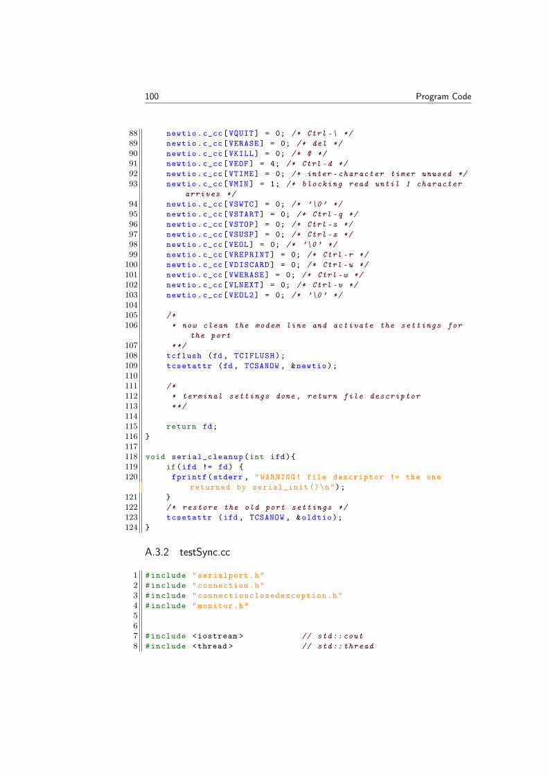
100 Program Code
88 newtio.c_cc[VQUIT] = 0; /* Ctrl -\ */89 newtio.c_cc[VERASE] = 0; /* del */90 newtio.c_cc[VKILL] = 0; /* @ */91 newtio.c_cc[VEOF] = 4; /* Ctrl -d */92 newtio.c_cc[VTIME] = 0; /* inter -character timer unused */93 newtio.c_cc[VMIN] = 1; /* blocking read until 1 character
arrives */94 newtio.c_cc[VSWTC] = 0; /* ’\0’ */95 newtio.c_cc[VSTART] = 0; /* Ctrl -q */96 newtio.c_cc[VSTOP] = 0; /* Ctrl -s */97 newtio.c_cc[VSUSP] = 0; /* Ctrl -z */98 newtio.c_cc[VEOL] = 0; /* ’\0’ */99 newtio.c_cc[VREPRINT] = 0; /* Ctrl -r */
100 newtio.c_cc[VDISCARD] = 0; /* Ctrl -u */101 newtio.c_cc[VWERASE] = 0; /* Ctrl -w */102 newtio.c_cc[VLNEXT] = 0; /* Ctrl -v */103 newtio.c_cc[VEOL2] = 0; /* ’\0’ */104105 /*106 * now clean the modem line and activate the settings for
the port107 **/108 tcflush (fd, TCIFLUSH);109 tcsetattr (fd, TCSANOW , &newtio);110111 /*112 * terminal settings done , return file descriptor113 **/114115 return fd;116 117118 void serial_cleanup(int ifd)119 if(ifd != fd) 120 fprintf(stderr , "WARNING! file descriptor != the one
returned by serial_init ()\n");121 122 /* restore the old port settings */123 tcsetattr (ifd , TCSANOW , &oldtio);124
A.3.2 testSync.cc
1 #include "serialport.h"2 #include "connection.h"3 #include "connectionclosedexception.h"4 #include "monitor.h"567 #include <iostream > // std::cout8 #include <thread > // std:: thread
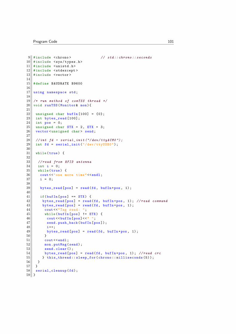
Program Code 101
9 #include <chrono > // std:: chrono :: seconds10 #include <sys/types.h>11 #include <unistd.h>12 #include <stdexcept >13 #include <vector >1415 #define BAUDRATE B96001617 using namespace std;1819 /* run method of comTSS thread */20 void runTSS(Monitor& mon)2122 unsigned char bufIn [100] = 0;23 int bytes_read [100];24 int pos = 0;25 unsigned char STX = 2, ETX = 3;26 vector <unsigned char > send;2728 //int fd = serial_init ("/dev/ttyACM0 ");29 int fd = serial_init("/dev/ttyUSB0");3031 while(true) 3233 //read from RFID antenna34 int i = 0;35 while(true) 36 cout <<"one more time"<<endl;37 i = 0;3839 bytes_read[pos] = read(fd , bufIn+pos , 1);4041 if(bufIn[pos] == STX) 42 bytes_read[pos] = read(fd , bufIn+pos , 1); //read command43 bytes_read[pos] = read(fd , bufIn+pos , 1);44 cout <<"Tag read: ";45 while(bufIn[pos] != ETX) 46 cout <<bufIn[pos]<<" ";47 send.push_back(bufIn[pos]);48 i++;49 bytes_read[pos] = read(fd , bufIn+pos , 1);50 51 cout <<endl;52 mon.putMsg(send);53 send.clear();54 bytes_read[pos] = read(fd , bufIn+pos , 1); //read crc55 this_thread :: sleep_for(chrono :: milliseconds (5));56 57 58 serial_cleanup(fd);59

102 Program Code
6061 /* run method of comRSURec thread */62 void runRSURec(Monitor& mon , shared_ptr <Connection >& conn) 6364 unsigned int recv_msg = 0;6566 while(true) 67 try68 recv_msg = conn ->read();6970 catch (ConnectionClosedException &) 71 cout << " no reply from server. Exiting." << endl;72 exit (1);73 74 this_thread :: sleep_for(chrono :: milliseconds (500));75 76 7778 /* run method of comRSUSend thread */79 void runcomRSUSend(Monitor& mon , shared_ptr <Connection >& conn ,
unsigned char id)80 vector <unsigned char > curMsg;81 vector <unsigned char > prevMsg;8283 try 84 conn ->write(’?’);85 conn ->write(’I’);86 conn ->write(id);87 conn ->write(’!’);88 catch (ConnectionClosedException &) 89 cout << " no reply from server. Exiting." << endl;90 exit (1);91 9293 while(true) 94 mon.getMsg(curMsg);95 if(curMsg != prevMsg)96 cout <<"curMsg != prevMsg"<<endl;9798 for(vector <unsigned char >:: iterator it = curMsg.begin() ;
it != curMsg.end(); ++it)99 try
100 conn ->write ((*it));101 cout <<" "<<*it;102103 catch (ConnectionClosedException &) 104 cout << " no reply from server. Exiting." << endl;105 exit (1);106 107 108 cout <<endl;
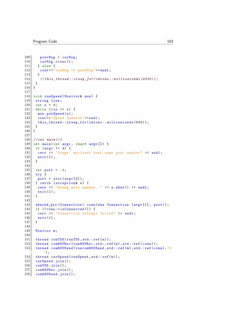
Program Code 103
109 prevMsg = curMsg;110 curMsg.clear();111 else 112 cout <<"curMsg == prevMsg"<<endl;113 114 // this_thread :: sleep_for(chrono :: milliseconds (2000));115 116 117118 void runSpeed(Monitor& mon) 119 string line;120 int s = 0;121 while (cin >> s) 122 mon.putSpeed(s);123 cout <<"Speed updated"<<endl;124 this_thread :: sleep_for(chrono :: milliseconds (500));125 126 127128 //int main()129 int main(int argc , char* argv []) 130 if (argc != 3) 131 cerr << "Usage: myclient host -name port -number" << endl;132 exit (1);133 134135 int port = -1;136 try 137 port = stoi(argv [2]);138 catch (exception& e) 139 cerr << "Wrong port number. " << e.what() << endl;140 exit (1);141 142143 shared_ptr <Connection > conn(new Connection (argv[1], port));144 if (!conn ->isConnected ()) 145 cerr << "Connection attempt failed" << endl;146 exit (1);147 148149 Monitor m;150151 thread comTSS(runTSS ,std::ref(m));152 thread comRSURec(runRSURec ,std::ref(m),std::ref(conn));153 thread comRSUSend(runcomRSUSend ,std::ref(m),std::ref(conn),’0
’);154 thread carSpeed(runSpeed ,std::ref(m));155 carSpeed.join();156 comTSS.join();157 comRSURec.join();158 comRSUSend.join();
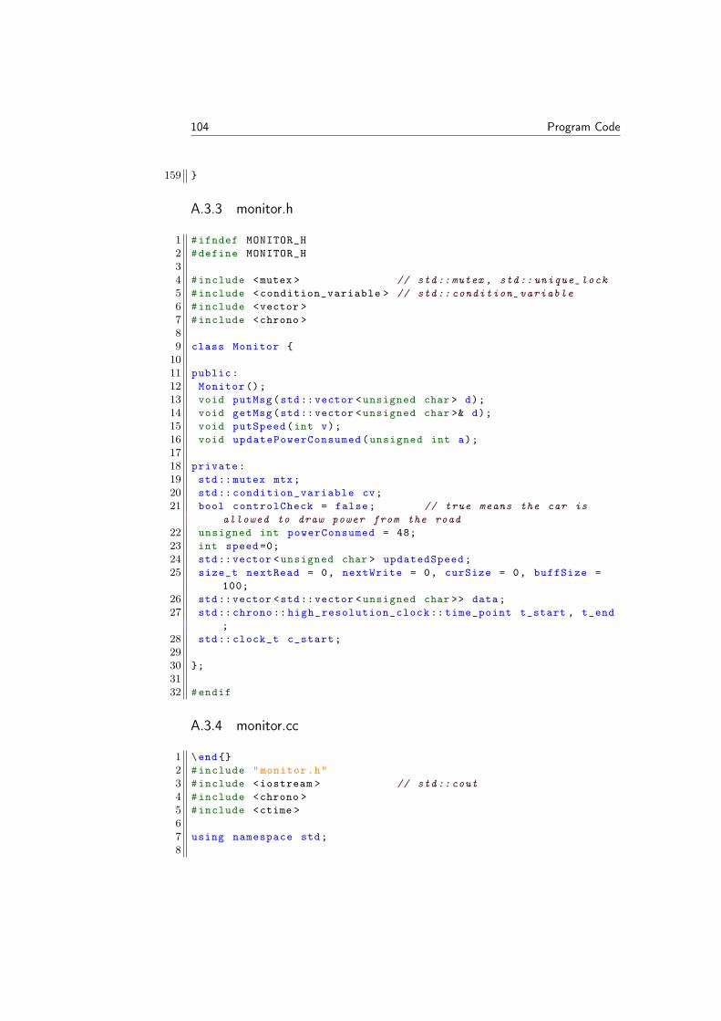
104 Program Code
159
A.3.3 monitor.h
1 #ifndef MONITOR_H2 #define MONITOR_H34 #include <mutex > // std::mutex , std:: unique_lock5 #include <condition_variable > // std:: condition_variable6 #include <vector >7 #include <chrono >89 class Monitor 1011 public:12 Monitor ();13 void putMsg(std::vector <unsigned char > d);14 void getMsg(std::vector <unsigned char >& d);15 void putSpeed(int v);16 void updatePowerConsumed(unsigned int a);1718 private:19 std:: mutex mtx;20 std:: condition_variable cv;21 bool controlCheck = false; // true means the car is
allowed to draw power from the road22 unsigned int powerConsumed = 48;23 int speed =0;24 std::vector <unsigned char > updatedSpeed;25 size_t nextRead = 0, nextWrite = 0, curSize = 0, buffSize =
100;26 std::vector <std::vector <unsigned char >> data;27 std:: chrono :: high_resolution_clock :: time_point t_start , t_end
;28 std:: clock_t c_start;2930 ;3132 #endif
A.3.4 monitor.cc
1 \end2 #include "monitor.h"3 #include <iostream > // std::cout4 #include <chrono >5 #include <ctime >67 using namespace std;8
Program Code 105
9 Monitor :: Monitor (): data(buffSize)1011 /* called by comTSS thread when it has read data from RFID
antennen */12 void Monitor :: putMsg(vector <unsigned char > d)13 unique_lock <mutex > lck(mtx); //take the mutex14 while(curSize == buffSize) cv.wait(lck);15 cout <<"in put msg";16 data[nextWrite ]. push_back(’?’);17 data[nextWrite ]. push_back(’S’);18 char s[4]=’0’,’0’,’0’,’0’;19 sprintf(s,"%03d",speed);20 data[nextWrite ]. push_back(s[0]);21 data[nextWrite ]. push_back(s[1]);22 data[nextWrite ]. push_back(s[2]);23 data[nextWrite ]. push_back(’T’);24 data[nextWrite ]. insert(data[nextWrite ].end(), d.begin(), d.
end());25 data[nextWrite ]. push_back(’!’);2627 for (vector <unsigned char >:: iterator it = (data[nextWrite ]).
begin() ; it != (data[nextWrite ]).end(); ++it)28 //cout << " " << hex << static_cast <unsigned int >(*it);29 cout << " " << *it;30 31 cout <<endl;32 nextWrite = (nextWrite + 1) % buffSize;33 curSize ++;34 lck.unlock (); // release the mutex35 cv.notify_all ();36 3738 /* called by comRSUSend thread */39 void Monitor :: getMsg(vector <unsigned char >& vec) 4041 unique_lock <mutex > lck(mtx);42 while(curSize == 0) cv.wait(lck);43 vec = data[nextRead ];44 data[nextRead ]. clear();45 nextRead = (nextRead + 1) % buffSize;46 curSize --;47 // c_start = clock();48 // t_start = chrono :: high_resolution_clock ::now();49 lck.unlock ();50 cv.notify_all ();51 5253 /* called by carSpeed */54 void Monitor :: putSpeed(int a) 55 unique_lock <mutex > lck(mtx);56 speed = a;
106 Program Code
57 char s[4]=’0’,’0’,’0’,’0’;58 sprintf(s,"%03d",speed);59 updatedSpeed.push_back(’S’);60 updatedSpeed.push_back(s[0]);61 updatedSpeed.push_back(s[1]);62 updatedSpeed.push_back(s[2]);63 lck.unlock ();64 cv.notify_all ();65 6667 /* called by comRSURec */68 void Monitor :: updatePowerConsumed(unsigned int a) 69 unique_lock <mutex > lck(mtx);70 // clock_t c_end = clock ();71 //t_end = chrono :: high_resolution_clock ::now();72 powerConsumed = a;73 cout <<"Power consumed updated: "<< a << endl;74 //cout << chrono ::duration <double , milli >(t_end -t_start).
count() << " ms\n"<<endl;75 //cout << 1000.0 * (c_end -c_start) / CLOCKS_PER_SEC << " ms\n
"<<endl;76 lck.unlock ();77 cv.notify_all ();78
A.3.5 connection.h
1 //------------------------------------------------------------------
2 //3 // Client/Server communication package4 //5 // Connection header file6 //7 // Change log8 // 950323 RH Initial version9 // 951212 RH Modified to allow subclassing of class Connection10 // 970127 RH Changed "private" to "protected"11 // 990125 PH Changed function names: Read -> read , etc.12 // 000114 PH int -> bool , virtual destructors , other minor
changes13 // 010129 PH added void type to initConnection14 // 011212 PH changed char* arguments to const char*15 // changed connection closed handling to exception16 // unsigned char instead of char/int in write/read17 // 020102 PH split into separate file for each class18 // 040421 PH added namespace , new casts , cleaned up a lot19 // 050113 PH added deregisterConnection , new registration (
vector),20 // added check for server shutdown , many more changes

Program Code 107
21 // 130515 PH removed namespace22 //23 //
------------------------------------------------------------------
2425 #ifndef CONNECTION_H26 #define CONNECTION_H2728 class Server;2930 /* A Connection object represents a connection (a socket) */31 class Connection 32 friend class Server;33 public:34 /* Establishes a connection to the computer ’host’ via35 the port ’port’ */36 Connection(const char* host , int port);3738 /* Creates a Connection object which will be initialized39 by the server */40 Connection ();4142 /* Closes the connection */43 virtual ~Connection ();4445 /* Returns true if the connection has been established */46 bool isConnected () const;4748 /* Writes a character */49 void write(unsigned char ch) const;5051 /* Reads a character */52 unsigned char read() const;5354 protected:55 /* The socket number that this connections communicates on */56 int my_socket;5758 /* Set to true when the constructor has called signal ()59 to ignore broken pipe. See comment in the constructor */60 static bool ignoresPipeSignals;6162 /* Initialization from server , receives socket number s */63 void initConnection(int s);6465 /* Server fetches the socket number */66 int getSocket () const;6768 /* Prints error message and exits */69 void error(const char* msg) const;
108 Program Code
70 ;7172 #endif
A.3.6 connection.cc
1 //------------------------------------------------------------------
2 //3 // Client/Server communication package4 //5 // Connection implementation file6 //7 // Change log8 // 950323 RH Initial version9 // 951212 RH Modified to allow subclassing of class Connection10 // 970127 RH Added extra include to make the file compile
under Linux11 // 990125 PH Changed function names: Read -> read , ...12 // 000114 PH int -> bool , virtual destructors , other minor
changes13 // 010129 PH added void type to initConnection14 // 011212 PH changed char* arguments to const char*15 // changed connection closed handling to exception16 // unsigned char instead of char/int in write/read17 // 020102 PH split into separate file for each class18 // 040421 PH added namespace , new casts , cleaned up a lot19 // 050113 PH added deregisterConnection , new registration (
vector),20 // added check for server shutdown , many more changes21 // 090127 PH added include of cstdlib , for exit()22 // 130515 PH removed namespace23 //24 //
------------------------------------------------------------------
2526 #include "connection.h"27 #include "connectionclosedexception.h"2829 #include <iostream >30 #include <cstdlib > /* exit() */31 #include <cstring > /* memcpy () */32 #include <csignal > /* signal () */33 #include <sys/types.h> /* socket (), connect (), read(), write
() */34 #include <sys/socket.h> /* socket (), connect () */35 #include <netdb.h> /* gethostbyname () */36 #include <arpa/inet.h> /* htons () */37 #include <unistd.h> /* close (), read(), write () */
Program Code 109
38 #include <sys/uio.h> /* read(), write() */39 #include <netinet/in.h> /* sockaddr_in */4041 bool Connection :: ignoresPipeSignals = false;4243 Connection :: Connection(const char* host , int port) 44 /*45 * Ignore SIGPIPE signals (broken pipe). A broken pipe (only
?)46 * occurs in a client , when it tries to write to a dead
server.47 * When the signal is ignored , :: write() returns -1 as the
count48 * of written bytes. Connection ::write() tests for this and49 * throws ConnectionClosedException when it happens.50 */51 if (! ignoresPipeSignals) 52 signal(SIGPIPE , SIG_IGN);53 ignoresPipeSignals = true;54 5556 my_socket = socket(AF_INET ,SOCK_STREAM , 0);57 if (my_socket < 0) 58 my_socket = -1;59 return;60 6162 sockaddr_in server;63 server.sin_family = AF_INET;64 hostent* hp = gethostbyname(host);65 if (hp == 0) 66 my_socket = -1;67 return;68 6970 memcpy(reinterpret_cast <char*>(& server.sin_addr),71 reinterpret_cast <char*>(hp->h_addr),72 hp ->h_length);73 server.sin_port = htons(port);74 if (connect(my_socket ,75 reinterpret_cast <sockaddr *>(& server),76 sizeof(server)) < 0) 77 my_socket = -1;78 79 8081 Connection :: Connection () 82 /*83 * See previous constructor for comments.84 */85 if (! ignoresPipeSignals)
110 Program Code
86 signal(SIGPIPE , SIG_IGN);87 ignoresPipeSignals = true;88 89 my_socket = -1;90 9192 Connection ::~ Connection () 93 if (my_socket != -1) 94 close(my_socket);95 96 9798 bool Connection :: isConnected () const 99 return my_socket != -1;
100 101102 void Connection :: write(unsigned char ch) const 103 if (my_socket == -1) 104 error("Write attempted on a not properly opened connection")
;105 106 int count = :: write(my_socket , &ch , 1);107 if (count != 1) 108 throw ConnectionClosedException ();109110 111 112113 unsigned char Connection ::read() const 114 if (my_socket == -1) 115 error("Read attempted on a not properly opened connection");116 117 char data = ’ ’;118 int count = ::read(my_socket , &data , 1);119 if (count != 1) 120 throw ConnectionClosedException ();121 return data;122 123 return data;124 125126 void Connection :: initConnection(int s) 127 my_socket = s;128 129130 int Connection :: getSocket () const 131 return my_socket;132 133134 void Connection :: error(const char* msg) const 135 std::cerr << "Class Connection: " << msg << std::endl;

Program Code 111
136 exit (1);137

112 Program Code
Bibliography
EPCglobal 2008, EPC Radio-Frequency Identity Protocols Class-1 Generation-2UHF RFID Protocol for Communications at 860 MHz – 960 MHz. EPC-global Inc., 2008. Version 1.2.0. Available at http://www.gs1.org/sites/default/files/docs/epc/uhfc1g2_1_2_0-standard-20080511.pdf, [2 De-cember 2015].
Energiläget 2013. Svenska statens energimyndighet, 2013. Available in printedform or at http://www.energimyndigheten.se/statistik/energilaget/.
Fossilfrihet på väg. Statens offentliga utredningar, 2013. ID-nummer: SOU2013:84.
Traffic Supervisions Systems TSS, 2015. Available at http://www.compprof-rtp.com/tss-tag/, [4 December 2015].
Elways, 2015. Available at http://elways.se, [4 December 2015].
eHighway, Siemens, 2016. Available at http://w3.siemens.se/home/se/sv/Mobility/interurban_mobility/road_solutions/elvagar-klimatsmarta-och-kostnadseffektiva-transporter/Pages/elvagar-klimatsmarta-och-kostnadseffektiva-transporter.aspx, [22 December 2016].
Philip Abrahamsson. Electro mechanic design and test of conductive electricalroad system - overall system design and protection. Master’s thesis, Division ofIndustrial Electrical Engineering and Automation Faculty of Engineering, LundUniversity, 2015. CODEN:LUTEDX/(TEIE-5349)/1-53/(2015).
Marcus Andersson. Electro mechanic design and test of conductive electrical roadsystem - primary power circui. Master’s thesis, Division of Industrial ElectricalEngineering and Automation Faculty of Engineering, Lund University, 2014.CODEN:LUTEDX/(TEIE-5348)/1-44(2014).
C.A. Balanis. Antenna theory. John Wiley & Sons, Inc., Hoboken, New Jersey,third edition, 2005. ISBN 978-0-471-66782-7.
S. Evdokimov, B. Fabian, O. Günter, Ivantysynova L., and H. Ziekow. RFIDand the Internet of Things: Technology, Applications and Security Challenges,
113

114 BIBLIOGRAPHY
Foundation and Trends in Technology, Information and Operations Manage-ment. Publishers Inc., 2010. ISBN 978-1-601-98444-9. Volume 4, no 2.
K. Finkenzeller. RFID Handbook: Fundamentals and applications in contactlesssmart cards, radio frequency identification and near-field communication. JohnWiley & Sons, Ltd, third edition, 2010. ISBN 978-0-470-69506-7.
E. H. Hall. On a new action of the magnet on electric currents. Technical report,American Journal of Mathematics 2, No. 3, pages 287–292., 1879. Available athttp://www.jstor.org/stable/2369245?seq=6#page_scan_tab_contents ,[15 January 2016].
Emil Landqvist and Theodor Hallerby. Thermal Modeling and Power Limitationof the ElOnRoad system - Modelation and simulation of the thermic capabili-ties. Master’s thesis, Division of Industrial Electrical Engineering and Automa-tion Faculty of Engineering, Lund University, 2015. CODEN:LUTEDX/(TEIE-5350)/1-65/2015).
K&J Magnetics. Surface fields 101, 2016. URL https://www.kjmagnetics.com/blog.asp?p=surface-fields-101. [28 February 2016].
NdFeB Specialists E-magnets UK. Grades of Neodymium, 2016. Available athttp://www.ndfeb-info.com/neodymium_grades.aspx,[20 February 2016].
Optys Corporation. OptRFID, High speed reader: reading tags at 43 & 113 km/h.2011. Available at https://www.youtube.com/watch?v=n2g_4Do_3R4, [2 De-cember 2015].
Naomi Oreskes. Vägar och gators utformning, VGU. Technical report, 2004. Sci-ence 03 Dec 2004: Vol. 306, Issue 5702, pp. 1686 DOI: 10.1126/science.1103618.
PTSFS. Post och telestyrelsens föreskrifter om undantag från tillståndsplikt för an-vändning av vissa radiosändare. Post och telestyrelse, 2015. Available at http://www.pts.se/upload/Foreskrifter/Radio/PTSFS-2015_4-undantag.pdf.
A.W. Rudge, K. Milne, Olver A.D., and Knight P. The handbook of antennadesign. Peter Peregrinus Ltd., London, UK, 1982. ISBN 978-0-906-04882-5.Volume 1.
Henrik Fritzon Sund. Electro mechanic design and test of conductive electricalroad system - implementation of the control unit. Master’s thesis, Division ofIndustrial Electrical Engineering and Automation Faculty of Engineering, LundUniversity, 2014. CODEN: LUTEDX/(TEIE-5327)/1-121/(2014).
Lee H. Thomas. The design of CMOS radio-frequency integrated circuits. Cam-bridge University Press, second edition, 2004. ISBN 978-0-521-83539-8.
A. Paul Tipler and Mosca Gene. Physics for scientists and engineers. W.H.Freeman and Company, New York, sixth edition, 2008.
VGU. Vägar och gators utformning, VGU. Technical report, 2004. Avail-able at http://www.trafikverket.se/TrvSeFiler/Foretag/Bygga_och_underhalla/Vag/Vagutformning/Dokument_vag_och_gatuutformning/
BIBLIOGRAPHY 115
Vagar_och_gators_utformning/Sektion_landsbygd-vagrum/sektion_%20landsbygd_vagrum.pdf,[30 November 2015].
R. Wermke, O. Wilmsmeier, and J. Regtmeier. How fast is fast? RFID iden-tifies objects up to 200 km/h. Harting Technology Group, 2014a. Availableat http://www.harting-rfid.com/fileadmin/harting/documents/rfid/aktuelles/fachartikel/Whitepaper_RFID_highspeed_HARTING.pdf, [2December 2015].
R. Wermke, O. Wilmsmeier, and J. Regtmeier. How fast is fast? RFID identifiesobjects up to 200 km/h. Harting Technology Group, 2014b. Available at https://www.youtube.com/watch?v=sZ9yE0Lw_so, [2 December 2015].
Zhang Xiaoqiang and Tentzeris Manos. Applications of Fast-Moving RFID Tagsin High-speed Railway Systems. Technical report, 2011. International Journalof Engineering Business Management. Volume 3, No. 1, pp. 27-31.

High speed detecting and identificationfor car charging on electric roads
IULIANA STOICA AND VIKTOR NYBOMMASTER´S THESISDEPARTMENT OF ELECTRICAL AND INFORMATION TECHNOLOGY |FACULTY OF ENGINEERING | LTH | LUND UNIVERSITY
Printed by Tryckeriet i E-huset, Lund 2017
IULIA
NA
STOIC
A A
ND
VIK
TOR
NY
BO
MH
igh speed detecting and identification for car charging on electric roads
LUN
D 2017
Series of Master’s thesesDepartment of Electrical and Information Technology
LU/LTH-EIT 2017-564
http://www.eit.lth.se