High-Speed Busbar Transfer
9
SYNCHROTACT ® HBT High-Speed Busbar Transfer M HB T M ~ ~
description
Electrical engineering
Transcript of High-Speed Busbar Transfer

7/16/2019 High-Speed Busbar Transfer
http://slidepdf.com/reader/full/high-speed-busbar-transfer 1/8
SYNCHROTACT® HBT
High-Speed Busbar Transfer
M
HBT
M
~ ~
7/16/2019 High-Speed Busbar Transfer
http://slidepdf.com/reader/full/high-speed-busbar-transfer 2/8
Main Features
High-speed busbar transfer
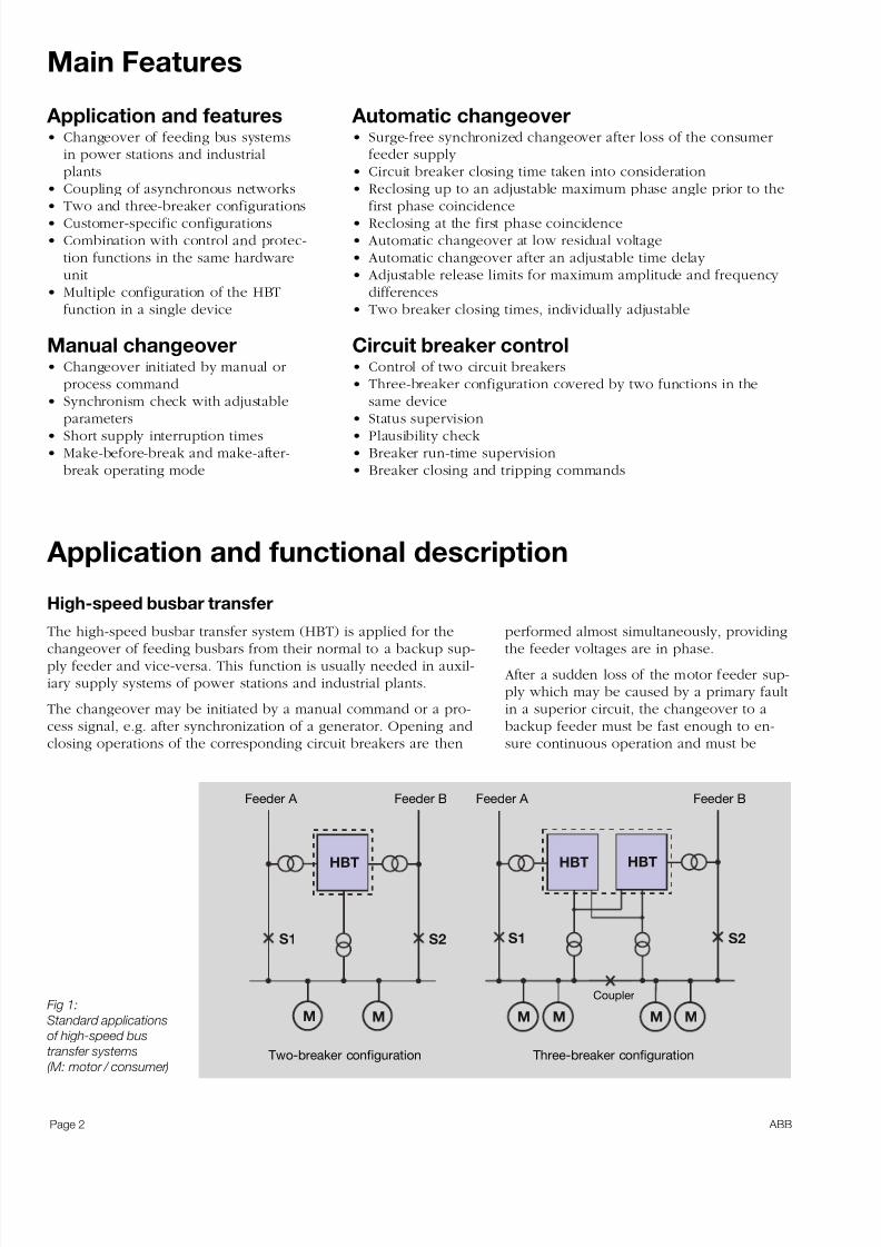
The high-speed busbar transfer system (HBT) is applied for thechangeover of feeding busbars from their normal to a backup sup-ply feeder and vice-versa. This function is usually needed in auxil-iary supply systems of power stations and industrial plants.
The changeover may be initiated by a manual command or a pro-cess signal, e.g. after synchronization of a generator. Opening andclosing operations of the corresponding circuit breakers are then
Application and features• Changeover of feeding bus systems
in power stations and industrialplants
• Coupling of asynchronous networks
• Two and three-breaker configurations• Customer-specific configurations• Combination with control and protec-
tion functions in the same hardwareunit
• Multiple configuration of the HBTfunction in a single device
Manual changeover• Changeover initiated by manual or
process command• Synchronism check with adjustable
parameters• Short supply interruption times• Make-before-break and make-after-
break operating mode
Automatic changeover• Surge-free synchronized changeover after loss of the consumer
feeder supply • Circuit breaker closing time taken into consideration• Reclosing up to an adjustable maximum phase angle prior to the
first phase coincidence• Reclosing at the first phase coincidence• Automatic changeover at low residual voltage• Automatic changeover after an adjustable time delay • Adjustable release limits for maximum amplitude and frequency
differences• Two breaker closing times, individually adjustable
Circuit breaker control• Control of two circuit breakers• Three-breaker configuration covered by two functions in the
same device
• Status supervision• Plausibility check• Breaker run-time supervision• Breaker closing and tripping commands
Application and functional description
performed almost simultaneously, providingthe feeder voltages are in phase.
After a sudden loss of the motor feeder sup-ply which may be caused by a primary faultin a superior circuit, the changeover to abackup feeder must be fast enough to en-sure continuous operation and must be
Fig 1:
Standard applications
of high-speed bus
transfer systems
(M: motor / consumer)
Page 2
HBT HBTHBT
S1 S2 S1 S2
M M M MM M
Feeder A Feeder A Feeder B Feeder B
Two-breaker configuration Three-breaker configuration
Coupler
ABB
7/16/2019 High-Speed Busbar Transfer
http://slidepdf.com/reader/full/high-speed-busbar-transfer 3/8
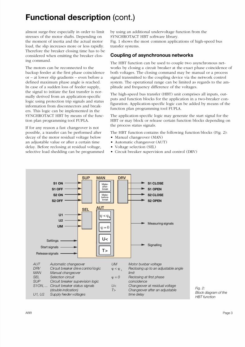
Fig. 2:
Block diagram of the
HBT function
AUT Automatic changeover
DRV Circuit breaker drive control logic
MAN Manual changeover
SEL Selection circuit
SUP Circuit breaker supervision logic
S1ON, ... Circuit breaker status signals
(double indication)
U1, U2 Supply feeder voltages
UM Motor busbar voltage
ϕ < ϕ L
Reclosing up to an adjustable angle
limit
ϕ = 0 Reclosing at first phase
coincidence
U< Changeover at residual voltage
T> Changeover after an adjustable
time delay
Functional description (cont.)
almost surge-free especially in order to limitstresses of the motor shafts. Depending onthe moment of inertia and the actual motorload, the slip increases more or less rapidly.Therefore the breaker closing time has to beconsidered when emitting the breaker clos-
ing command.
The motors can be reconnected to thebackup feeder at the first phase coincidenceor – at lower slip gradients – even before adefined maximum phase angle is reached.In case of a sudden loss of feeder supply,the signal to initiate the fast transfer is nor-mally derived from an application-specificlogic using protection trip signals and statusinformation from disconnectors and break-ers. This logic can be implemented in theSYNCHROTACT HBT by means of the func-tion plan programming tool FUPLA.
If for any reason a fast changeover is notpossible, a transfer can be performed afterdecay of the motor residual voltage below an adjustable value or after a certain timedelay. Before reclosing at residual voltage,selective load shedding can be programmed
by using an additional undervoltage function from theSYNCHROTACT HBT software library.Fig. 1 shows the most common applications of high-speed bustransfer systems.
Coupling of asynchronous networks
The HBT function can be used to couple two asynchronous net- works by closing a circuit breaker at the exact phase coincidence of both voltages. The closing command may be manual or a processsignal transmitted to the coupling device via the network controlsystem. The operational range can be limited as regards to the am-plitude and frequency difference of the voltages.
The high-speed bus transfer (HBT) unit comprises all inputs, out-puts and function blocks for the application in a two-breaker con-figuration. Application-specific logic can be added by means of thefunction plan programming tool FUPLA.
The application-specific logic may generate the start signal for theHBT or may block or release certain function blocks depending onthe process status signals.
The HBT function contains the following function blocks (Fig. 2):• Manual changeover (MAN)• Automatic changeover (AUT)• Voltage selection (SEL)• Circuit breaker supervision and control (DRV)
Page 3
ϕ<ϕL
T>
U<
MAN
AUT
DRV SUP
SEL
U1
U2
UM ϕ = 0
S1 ON
S1 OFF
S2 ON
S2 OFF
S1 CLOSE
S1 OPEN
S2 CLOSE
S2 OPEN
Settings
Start signals
Release signals
Measuring signals
Signalling
Make-after-break
Make-before-break
ABB
7/16/2019 High-Speed Busbar Transfer
http://slidepdf.com/reader/full/high-speed-busbar-transfer 4/8
Functional description (cont.)
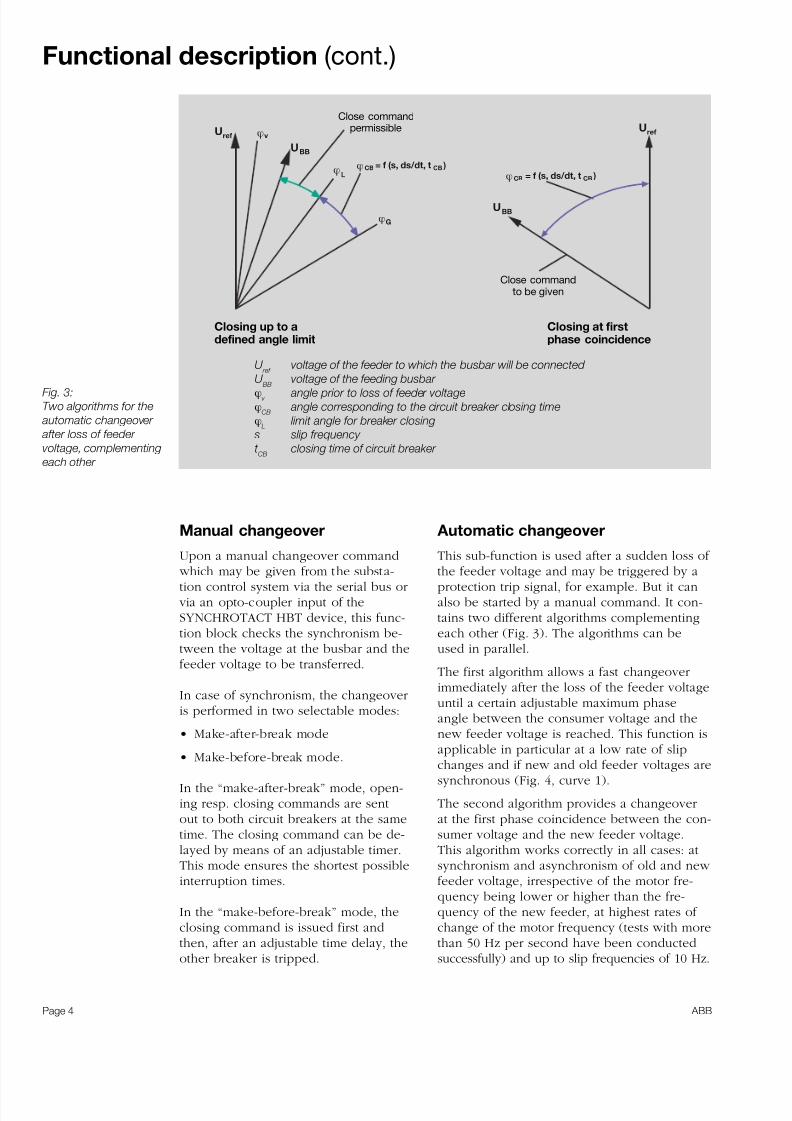
Fig. 3:
Two algorithms for the
automatic changeover
after loss of feeder
voltage, complementing
each other
Manual changeover
Upon a manual changeover command
which may be given from the substa-tion control system via the serial bus or via an opto-coupler input of theSYNCHROTACT HBT device, this func-tion block checks the synchronism be-tween the voltage at the busbar and thefeeder voltage to be transferred.
In case of synchronism, the changeoveris performed in two selectable modes:
• Make-after-break mode
• Make-before-break mode.
In the “make-after-break” mode, open-ing resp. closing commands are sentout to both circuit breakers at the sametime. The closing command can be de-layed by means of an adjustable timer.This mode ensures the shortest possibleinterruption times.
In the “make-before-break” mode, theclosing command is issued first andthen, after an adjustable time delay, the
other breaker is tripped.
Automatic changeover
This sub-function is used after a sudden loss of
the feeder voltage and may be triggered by aprotection trip signal, for example. But it canalso be started by a manual command. It con-tains two different algorithms complementingeach other (Fig. 3). The algorithms can beused in parallel.
The first algorithm allows a fast changeoverimmediately after the loss of the feeder voltageuntil a certain adjustable maximum phaseangle between the consumer voltage and thenew feeder voltage is reached. This function isapplicable in particular at a low rate of slip
changes and if new and old feeder voltages aresynchronous (Fig. 4, curve 1).
The second algorithm provides a changeoverat the first phase coincidence between the con-sumer voltage and the new feeder voltage.This algorithm works correctly in all cases: atsynchronism and asynchronism of old and new feeder voltage, irrespective of the motor fre-quency being lower or higher than the fre-quency of the new feeder, at highest rates of change of the motor frequency (tests with morethan 50 Hz per second have been conducted
successfully) and up to slip frequencies of 10 Hz.
Page 4
Uref
ϕG
Uref
ϕCB CB)= f (s, ds/dt, tϕCB CB)= f (s, ds/dt, t
UBB
UBB
ϕv
ϕL
Close commandpermissible
Close commandto be given
Closing up to adefined angle limit
Closing at firstphase coincidence
U ref
voltage of the feeder to which the busbar will be connected
U BB voltage of the feeding busbar ϕ
v angle prior to loss of feeder voltage
ϕCB
angle corresponding to the circuit breaker closing time
ϕL
limit angle for breaker closing
s slip frequency
t CB
closing time of circuit breaker
ABB

7/16/2019 High-Speed Busbar Transfer
http://slidepdf.com/reader/full/high-speed-busbar-transfer 5/8
Functional description (cont.)
Curve Slip before c.b. tripping (%) Rate of change of the slip (% per s)
1 0.5 6
2 2 6
3 0.5 25
4 2 25
Fig. 4:
Angle difference
between the voltage at
the feeding busbar and
the supply feeder
voltage versus time
after tripping of the
circuit breaker.
Fig. 4 shows how the angle difference be-tween motor voltage and supply voltage will develop over the time after tripping of the supply feeder, depending on the initialslip and the rate of slip change mirroringthe actual load conditions.
For both algorithms the breaker closing timeis taken into account. The correspondingphase angle is calculated considering theslip as well as the speed of the slip change.
Secondary changeover modes
These additional function blocks use sim-pler criteria because they do not check thesynchronism between the voltages. Twodifferent modes can be activated in parallel:
• Minimum voltage• Maximum time.
The “Minimum voltage” mode permits achangeover after the residual voltage at themotor bus decayed below an adjustable
threshold. A typical setting is 30 %.
The “Maximum time” mode provides achangeover after the adjustable time delay has expired, independent of the synchro-nism.
Voltage selection
The voltage of the feeding busbar is com-pared with a reference voltage to checksynchronism. In Fig. 1 this reference voltageis U2 (feeder 2) if feeder 1 is connected and
feeder 2 disconnected and vice versa. Theselection of the right voltage is performedaccording to the start signals for the manual,resp. automatic transfer.
Circuit breaker supervision andcontrol
The status signals of two circuit breakers arecollected and checked for plausibility. Anabnormal condition generates an alarm andblocks the changeover function. A breaker
run-time supervision is included.
Page 5
360
320
280
240
200
160
120
80
40
0
0 0.1 0.2 0.3 0.4 0.5 0.6 0.7 0.8
1
34
2
Time (s)
Angle(Degrees)
ABB
7/16/2019 High-Speed Busbar Transfer
http://slidepdf.com/reader/full/high-speed-busbar-transfer 6/8
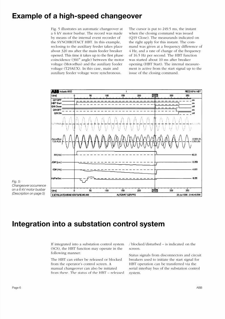
Fig. 5 illustrates an automatic changeover ata 6 kV motor busbar. The record was madeby means of the internal event recorder of the SYNCHROTACT HBT. In this example,reclosing to the auxiliary feeder takes placeabout 320 ms after the main feeder breaker
opened. This time it takes up to the first phasecoincidence (360° angle) between the motor voltage (MotorBus) and the auxiliary feeder voltage (T29AUX). In this case, main andauxiliary feeder voltage were synchronous.
Example of a high-speed changeover
The cursor is put to 249.5 ms, the instant when the closing command was issued(Q19 Close). The measurands indicated onthe right apply for this instant. The com-mand was given at a frequency difference of 4 Hz, and a rate of change of the frequency
of 16.5 Hz per second. The HBT function was started about 10 ms after breakeropening (HBT Start). The internal measure-ment is active from the start signal up to theissue of the closing command.
Fig. 5:
Changeover occurrence
on a 6 kV motor busbar
(Description on page 5)
Integration into a substation control system
If integrated into a substation control system(SCS), the HBT function may operate in thefollowing manner:
The HBT can either be released or blockedfrom the operator’s control screen. Amanual changeover can also be initiated
from there. The status of the HBT – released
/ blocked/disturbed – is indicated on thescreen.
Status signals from disconnectors and circuitbreakers used to initiate the start signal forHBT operation can be transferred via theserial interbay bus of the substation control
system.
Page 6 ABB
7/16/2019 High-Speed Busbar Transfer
http://slidepdf.com/reader/full/high-speed-busbar-transfer 7/8
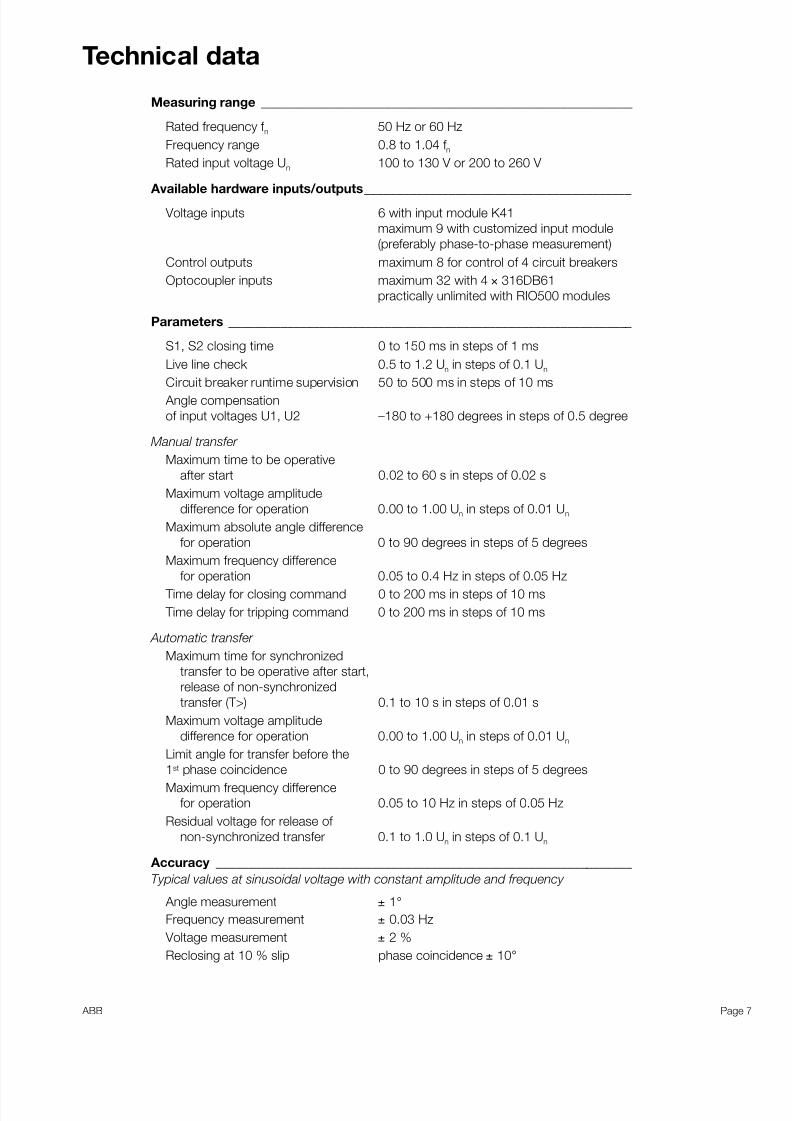
Technical data
Measuring range _________________________________________________________
Rated frequency f n 50 Hz or 60 Hz
Frequency range 0.8 to 1.04 f n
Rated input voltage Un 100 to 130 V or 200 to 260 V
Available hardware inputs/outputs_________________________________________
Voltage inputs 6 with input module K41
maximum 9 with customized input module
(preferably phase-to-phase measurement)
Control outputs maximum 8 for control of 4 circuit breakers
Optocoupler inputs maximum 32 with 4 × 316DB61
practically unlimited with RIO500 modules
Parameters ______________________________________________________________
S1, S2 closing time 0 to 150 ms in steps of 1 ms
Live line check 0.5 to 1.2 Un in steps of 0.1 Un
Circuit breaker runtime supervision 50 to 500 ms in steps of 10 ms Angle compensation
of input voltages U1, U2 –180 to +180 degrees in steps of 0.5 degree
Manual transfer
Maximum time to be operative
after start 0.02 to 60 s in steps of 0.02 s
Maximum voltage amplitude
difference for operation 0.00 to 1.00 Un in steps of 0.01 Un
Maximum absolute angle difference
for operation 0 to 90 degrees in steps of 5 degrees
Maximum frequency difference
for operation 0.05 to 0.4 Hz in steps of 0.05 Hz Time delay for closing command 0 to 200 ms in steps of 10 ms
Time delay for tripping command 0 to 200 ms in steps of 10 ms
Automatic transfer
Maximum time for synchronized
transfer to be operative after start,
release of non-synchronized
transfer (T>) 0.1 to 10 s in steps of 0.01 s
Maximum voltage amplitude
difference for operation 0.00 to 1.00 Un in steps of 0.01 Un
Limit angle for transfer before the
1st phase coincidence 0 to 90 degrees in steps of 5 degrees
Maximum frequency difference
for operation 0.05 to 10 Hz in steps of 0.05 Hz
Residual voltage for release of
non-synchronized transfer 0.1 to 1.0 Un in steps of 0.1 Un
Accuracy ________________________________________________________________
Typical values at sinusoidal voltage with constant amplitude and frequency
Angle measurement ± 1°
Frequency measurement ± 0.03 Hz
Voltage measurement ± 2 %
Reclosing at 10 % slip phase coincidence ± 10°
Page 7 ABB

7/16/2019 High-Speed Busbar Transfer
http://slidepdf.com/reader/full/high-speed-busbar-transfer 8/8
ABB Switzerland Ltd.
Static Excitation Systems, Voltage Regulators
and Synchronizing Equipment
CH-5300 Turgi / Switzerland
Telephone: +41 (0) 58 589 24 86
Fax: +41 (0) 58 589 23 33
Email: [email protected]
Internet: www.abb.com / synchrotact 3B
HT
490
196
R0201
PrintedinSwitzerland(0301-PDF)
We reserve the right to change in the interest of technical development.
Dimensional drawing
All measures in the graphics in mm
Panel cutout (W × H) 265 × 254 mm
5
8
7
6
3
4
1
2
13
16
15
14
11
12
9
10
16
18
17
15
14
8
13
12
11
10
9
5
7
6
4
3
2
1
OUT
IN
SYNCHROTACT HBT ®
2 7 6
271
c a .
3 3 4
c a . 2
9 0
2 7 .
5
C
E
Mounting elements(2 on upper shape, 2 on lower)
Front view Rear view
View from top View of the device