High Precision RF Control for SRF Cavities in LCLS-II · a possibility to upgrade that to a...
7
HIGH PRECISION RF CONTROL FOR SRF CAVITIES IN LCLS-II L. Doolittle ∗ , K. Campbell, Q. Du, G. Huang, J. Jones, C. Serrano, V. Vytla, LBNL, Berkeley, CA 94720, USA S. Babel, A. Benwell, M. Boyes, G. Brown, D. Cha, G. Dalit, J. DeLong, J. Diaz-Cruz, B. Hong, R. Kelly, A. McCollough, A. Ratti, C. Rivetta, SLAC, Menlo Park, CA 94720, USA R. Bachimanchi, C. Hovater, D. Seidman, JLab, Newport News, VA 23606, USA B. Chase, E. Cullerton, J. Einstein, D. Klepec, FNAL, Batavia, IL 60555, USA ABSTRACT The unique properties of SRF cavities enable a new gen- eration of X-ray light sources in XFEL and LCLS-II. The LCLS-II design calls for 280 L-band cavities to be operated in CW mode with a Q L of 4 × 10 7 , using Single-Source Single-Cavity control. The target RF field stability is 0.01% and 0.01 ◦ for the band above 1Hz. Hardware and software implementing a digital LLRF system has been constructed by a four-lab collaboration to minimize known contributors to cavity RF field fluctuation. Efforts include careful attach- ment to the phase reference line, and minimizing the effects of RF crosstalk by placing forward and reverse signals in chassis separate from the cavity measurement. A low-noise receiver/digitizer section will allow feedback to operate with high proportional gain without excessive noise being sent to the drive amplifier. Test results will show behavior on pro- totype cryomodules at FNAL and JLab, ahead of the 2018 final accelerator installation. INTRODUCTION LCLS-II is an X-ray Free Electron Laser (FEL) under con- struction at SLAC, driven by a superconducting RF Linac [1]. The electron beam quality will directly translate to the qual- ity of the X-ray beams produced in undulators and used for scientific research in the end stations; hence strict require- ments have been placed on the stability of the accelerating cavity fields. An initial stability goal of 0.01 ◦ in phase and 0.01% amplitude has been set for the main Linac, composed of 280 nine-cell 1300 MHz superconducting cavities [2]. Plans for the RF controls for the 1.3GHz cavities have been described elsewhere [3] [4] [5] [6]. It is based on main- stream digital LLRF technology, and incorporates many ideas developed for LBNL’s NGLS proposal [7]. The con- trols use a Single Source Single Cavity (SSSC) architec- ture, where each cavity has a dedicated amplifier. SSSC has enormous value for simplifying control of narrow-band SRF cavities, It is also a sensible choice for a CW machine, where Solid-State Amplifier technology has approximately matched Klystrons in price, and they are considered easier to operate and maintain. The LLRF subsystem of LCLS-II is itself a four-laboratory collaboration: LBNL for architecture, FPGA hardware and RF DSP programming, and ADC/DAC hardware develop- ment; Fermilab for downconverters, upconverters and piezo ∗ [email protected]; This work supported under DOE Contract DE-AC02- 76SF00515 EPICS Timing MPS Beam Feedback Resonance Control Piezo & Stepper RF Station Feedback Algorithms Exception Handling Precision Receiver Cavity Signals Phase Reference Line GB Fiber/Cavity Signals Forward & Reverse Power 3.8 kW Solid State Amplifier 1.3 GHz Superconducting Cavities GigE Cavity Signals Figure 1: System hardware configuration supporting half of a cryomodule (one of two RF Station chassis shown). drivers; JLab for interlocks, stepper controls, and power sup- plies; and SLAC for LO distribution, MO and PRL, global control system integration, commissioning, transition to op- erations, and project management. SYSTEM DESIGN Each rack (supporting four cavities) includes a separate Precision Receiver Chassis (PRC), linked only by optical fiber to two RF Control Chassis (RFS), as shown in figure 1. This density of rack equipment matches the civil layout of the accelerator, where one LLRF rack is cabled to one pene- tration to the tunnel. The physical separation between PRC and RFS maximizes isolation between the critical stabilized cavity signals and the wildly fluctuating forward and reverse monitoring channels. Preliminary measurements show that this separation has succeeded, in that the measured isolation is at least 125 dB. The system bypasses some of the usual compromises in choosing an IF by means of an unusual split-LO design, where a low-frequency IF (20MHz) is used for RF down- conversion, and a higher-frequency IF (145MHz) is used for RF upconversion. The downconversion IF is 7/33 of the ADC clock rate, yielding near-IQ sampling [8]. The low downconversion IF is good for selecting low-1/ f -noise amplifiers, and for reduc- ing crosstalk. The 94.3 MHz ADC clock rate is high enough that the whole 9-cell TM 010 passband (1274-1300 MHz) fits in the first Nyquist zone. The high upconversion IF allows commercial four-section tubular filters with 45 MHz band- width to remove the undesired sideband after mixing. 18th International Conference on RF Superconductivity SRF2017, Lanzhou, China JACoW Publishing ISBN: 978-3-95450-191-5 doi:10.18429/JACoW-SRF2017-FRXBA02 FRXBA02 944 Content from this work may be used under the terms of the CC BY 3.0 licence (© 2017). Any distribution of this work must maintain attribution to the author(s), title of the work, publisher, and DOI. SRF Technology R&D Ancillaries
Transcript of High Precision RF Control for SRF Cavities in LCLS-II · a possibility to upgrade that to a...
HIGH PRECISION RF CONTROL FOR SRF CAVITIES IN LCLS-IIL. Doolittle∗, K. Campbell, Q. Du, G. Huang, J. Jones,C. Serrano, V. Vytla, LBNL, Berkeley, CA 94720, USA
S. Babel, A. Benwell, M. Boyes, G. Brown, D. Cha, G. Dalit, J. DeLong, J. Diaz-Cruz,B. Hong, R. Kelly, A. McCollough, A. Ratti, C. Rivetta, SLAC, Menlo Park, CA 94720, USA
R. Bachimanchi, C. Hovater, D. Seidman, JLab, Newport News, VA 23606, USAB. Chase, E. Cullerton, J. Einstein, D. Klepec, FNAL, Batavia, IL 60555, USA
ABSTRACTThe unique properties of SRF cavities enable a new gen-
eration of X-ray light sources in XFEL and LCLS-II. The
LCLS-II design calls for 280 L-band cavities to be operated
in CW mode with a QL of 4 × 10⁷, using Single-SourceSingle-Cavity control. The target RF field stability is 0.01%
and 0.01◦ for the band above 1Hz. Hardware and softwareimplementing a digital LLRF system has been constructed
by a four-lab collaboration to minimize known contributors
to cavity RF field fluctuation. Efforts include careful attach-
ment to the phase reference line, and minimizing the effects
of RF crosstalk by placing forward and reverse signals in
chassis separate from the cavity measurement. A low-noise
receiver/digitizer section will allow feedback to operate with
high proportional gain without excessive noise being sent to
the drive amplifier. Test results will show behavior on pro-
totype cryomodules at FNAL and JLab, ahead of the 2018
final accelerator installation.
INTRODUCTIONLCLS-II is an X-ray Free Electron Laser (FEL) under con-
struction at SLAC, driven by a superconducting RF Linac [1].
The electron beam quality will directly translate to the qual-
ity of the X-ray beams produced in undulators and used for
scientific research in the end stations; hence strict require-
ments have been placed on the stability of the accelerating
cavity fields. An initial stability goal of 0.01◦ in phase and0.01% amplitude has been set for the main Linac, composed
of 280 nine-cell 1300MHz superconducting cavities [2].
Plans for the RF controls for the 1.3GHz cavities have
been described elsewhere [3] [4] [5] [6]. It is based on main-
stream digital LLRF technology, and incorporates many
ideas developed for LBNL’s NGLS proposal [7]. The con-
trols use a Single Source Single Cavity (SSSC) architec-
ture, where each cavity has a dedicated amplifier. SSSC
has enormous value for simplifying control of narrow-band
SRF cavities, It is also a sensible choice for a CW machine,
where Solid-State Amplifier technology has approximately
matched Klystrons in price, and they are considered easier
to operate and maintain.
The LLRF subsystem of LCLS-II is itself a four-laboratory
collaboration: LBNL for architecture, FPGA hardware and
RF DSP programming, and ADC/DAC hardware develop-
ment; Fermilab for downconverters, upconverters and piezo
∗ [email protected]; This work supported under DOE Contract DE-AC02-
76SF00515
EPICS Timing MPS Beam Feedback
Resonance Control Piezo & Stepper
RF Station Feedback Algorithms Exception Handling
Precision Receiver Cavity Signals Phase Reference Line
GB Fiber/Cavity Signals
Forward & Reverse Power
3.8 kW Solid State Amplifier
1.3 GHz Superconducting Cavities
GigE
Cavity Signals
Figure 1: System hardware configuration supporting half of
a cryomodule (one of two RF Station chassis shown).
drivers; JLab for interlocks, stepper controls, and power sup-
plies; and SLAC for LO distribution, MO and PRL, global
control system integration, commissioning, transition to op-
erations, and project management.
SYSTEM DESIGNEach rack (supporting four cavities) includes a separate
Precision Receiver Chassis (PRC), linked only by optical
fiber to two RF Control Chassis (RFS), as shown in figure 1.
This density of rack equipment matches the civil layout of
the accelerator, where one LLRF rack is cabled to one pene-
tration to the tunnel. The physical separation between PRC
and RFS maximizes isolation between the critical stabilized
cavity signals and the wildly fluctuating forward and reverse
monitoring channels. Preliminary measurements show that
this separation has succeeded, in that the measured isolation
is at least 125 dB.
The system bypasses some of the usual compromises in
choosing an IF by means of an unusual split-LO design,
where a low-frequency IF (20MHz) is used for RF down-
conversion, and a higher-frequency IF (145MHz) is used
for RF upconversion.
The downconversion IF is 7/33 of the ADC clock rate,
yielding near-IQ sampling [8]. The low downconversion IF
is good for selecting low-1/ f -noise amplifiers, and for reduc-ing crosstalk. The 94.3MHz ADC clock rate is high enough
that the whole 9-cell TM010 passband (1274-1300MHz) fits
in the first Nyquist zone. The high upconversion IF allows
commercial four-section tubular filters with 45MHz band-
width to remove the undesired sideband after mixing.
18th International Conference on RF Superconductivity SRF2017, Lanzhou, China JACoW PublishingISBN: 978-3-95450-191-5 doi:10.18429/JACoW-SRF2017-FRXBA02
FRXBA02944
Cont
entf
rom
this
wor
km
aybe
used
unde
rthe
term
soft
heCC
BY3.
0lic
ence
(©20
17).
Any
distr
ibut
ion
ofth
isw
ork
mus
tmai
ntai
nat
tribu
tion
toth
eau
thor
(s),
title
ofth
ew
ork,
publ
isher
,and
DO
I.
SRF Technology R&DAncillaries
Separating transmit and receive signals in the frequency
domain has the added advantage of removing a perennial
source of crosstalk from the drive back to RF inputs. There
is a small additional complication of needing to generate the
upconversion LO; the numbers have been chosen so that a
simple divide-by-eight of the downconversion LO produces
165MHz, which is mixed with the LO and filtered (using an-
other tubular filter) to generate the 1155MHz upconversion
LO.
LOW NOISE ANALOG/RF DESIGNAn RF Downconverter circuit board uses a 1320MHz
LO, distributed to each of the racks, to generate a 20MHz
IF for digitization. This board uses careful RF design and to
achieve typically -90 dB channel-channel crosstalk. It also
acts as an LO distribution module for the chassis.
The system’s digitizer board [9] is based on the AD9653
four-channel ADC. Its 94.3MHz sampling clock is derived
by dividing the 1320MHz LO by 14. The digitizer board
uses FMC connectors to attach to the FPGA carrier, although
it does not adhere to standard mechanical outlines. This
board includes two channels of DAC output that synthesize
the 145MHz output used for field control. It also has fea-
tures that are selected for clean chassis integration in this
application, keeping the number of connectors and boards
to a minimum.
Both the digitizer and RF downconversion hardware are
mounted on a 6mm aluminum plate to keep their compo-
nent temperatures stable. They also both use low-noise LDO
voltage regulators to avoid injecting noise from power sup-
plies into the signal path. Those low-noise regulators use a
capacitor to filter the voltage reference at audio frequencies;
non-piezoelectric capacitors are used to avoid picking up
environmental mechanical noise (e.g., fans).
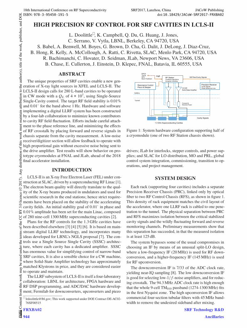
Differential phase noise of a completed RF chassis was
measured using a 1300MHz source passively split to two
input channels. After digital downconversion, filtering, and
decimation, long data traces were saved for analysis. One
such resulting differential phase noise power spectrum den-
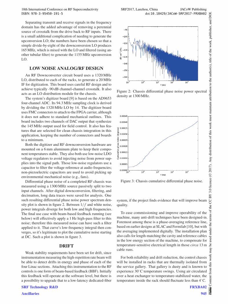
sity plot is shown in figure 2. Between 1/ f and white noise,power integrals diverge for both low and high frequencies.
The final use case with beam-based feedback running (see
below) will effectively apply a 1Hz high-pass filter to this
noise; therefore this measured noise can have such a filter
applied to it. That curve’s low-frequency integral then con-
verges, so it’s legitimate to plot the cumulative noise starting
at DC. Such a plot is shown in figure 3.
DRIFTWeak stability requirements have been set for drift, since
instrumentationmeasuring the high-repetition rate beamwill
be able to detect drifts in energy and phase of each of the
four Linac sections. Attaching this instrumentation to the RF
controls is one form of beam-based feedback (BBF). Initially
this feedback will operate at the software level, but there is
a possibility to upgrade that to a low-latency dedicated-fiber
Figure 2: Chassis differential phase noise power spectral
density at 1300MHz.
Figure 3: Chassis cumulative differential phase noise.
system, if the project finds evidence that will improve beam
quality.
To ease commissioning and improve operability of the
machine, many anti-drift techniques have been designed-in.
Foremost among these is a phase-averaging reference line,
based on earlier designs at SLAC and Fermilab [10], but with
the averaging implemented digitally. The installation plan
also calls for length-matching the cavity and reference cables
in the low energy section of the machine, to compensate for
temperature-sensitive electrical length in those circa 13mcable runs.
For both reliability and drift reduction, the control chassis
will be installed in racks that are thermally isolated from
the service gallery. That gallery is dusty and is known to
experience 30◦C temperature swings. Using air circulated
over a heat exchanger to temperature-stabilized water, the
temperature inside the rack should fluctuate less than 4◦C.
18th International Conference on RF Superconductivity SRF2017, Lanzhou, China JACoW PublishingISBN: 978-3-95450-191-5 doi:10.18429/JACoW-SRF2017-FRXBA02
SRF Technology R&DAncillaries
FRXBA02945
Cont
entf
rom
this
wor
km
aybe
used
unde
rthe
term
soft
heCC
BY3.
0lic
ence
(©20
17).
Any
distr
ibut
ion
ofth
isw
ork
mus
tmai
ntai
nat
tribu
tion
toth
eau
thor
(s),
title
ofth
ew
ork,
publ
isher
,and
DO
I.
XY
R
θ
amp setphase set
phase offset
X
Y
θ
XY
cavity measurement
DAC
Σset point ∫
=
KIconfigurable saturation
CORDIC CORDIC
KP
Σ
DC rejectDigital Down
Converter Encoding
DecodingNotch Filter
Digital Up Converter
ADC
2.5 Gbaud fiber link shared for two cavities
I/Q
Precision Receiver Chassis
RF Station Chassis
Low-pass &
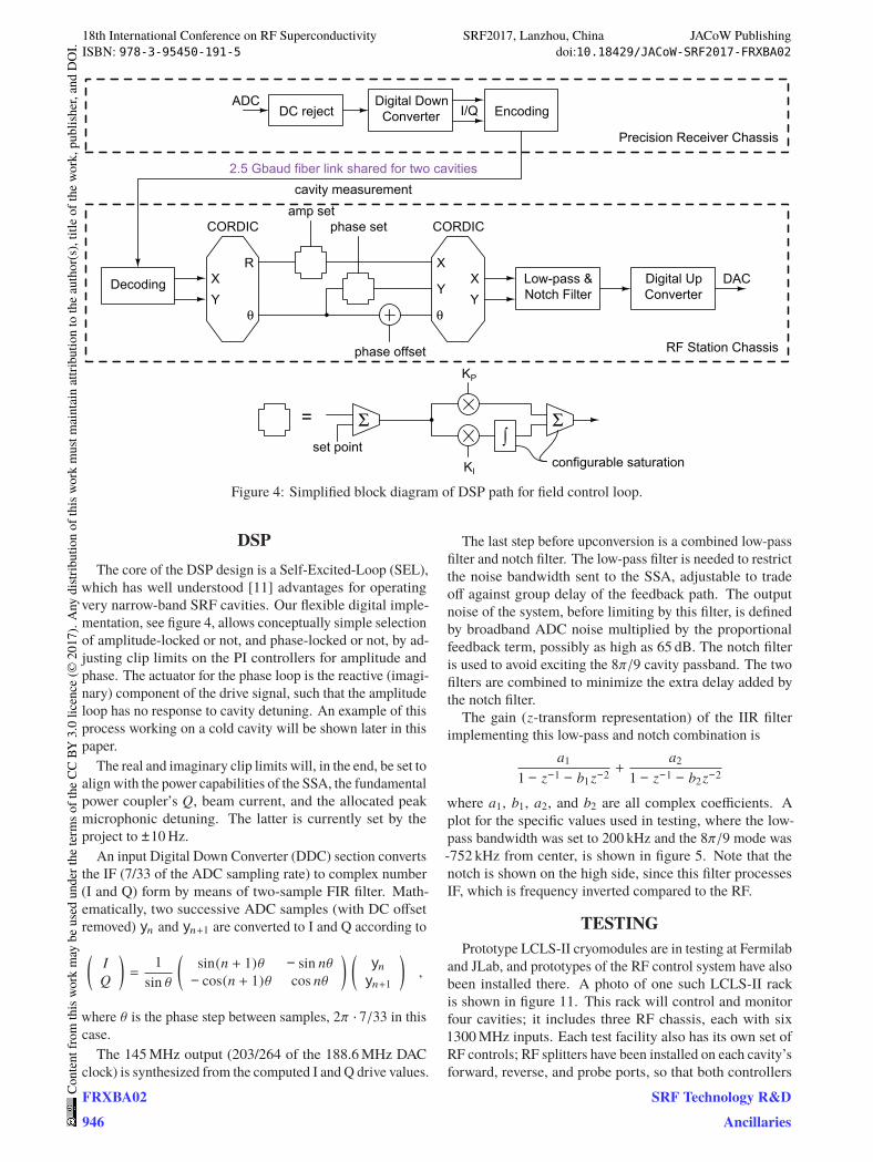
Figure 4: Simplified block diagram of DSP path for field control loop.
DSPThe core of the DSP design is a Self-Excited-Loop (SEL),
which has well understood [11] advantages for operating
very narrow-band SRF cavities. Our flexible digital imple-
mentation, see figure 4, allows conceptually simple selection
of amplitude-locked or not, and phase-locked or not, by ad-
justing clip limits on the PI controllers for amplitude and
phase. The actuator for the phase loop is the reactive (imagi-
nary) component of the drive signal, such that the amplitude
loop has no response to cavity detuning. An example of this
process working on a cold cavity will be shown later in this
paper.
The real and imaginary clip limits will, in the end, be set to
align with the power capabilities of the SSA, the fundamental
power coupler’s Q, beam current, and the allocated peak
microphonic detuning. The latter is currently set by the
project to ±10Hz.An input Digital Down Converter (DDC) section converts
the IF (7/33 of the ADC sampling rate) to complex number
(I and Q) form by means of two-sample FIR filter. Math-
ematically, two successive ADC samples (with DC offset
removed) yn and yn+1 are converted to I and Q according to
(IQ
)=
1
sin θ
(sin(n + 1)θ − sin nθ− cos(n + 1)θ cos nθ
) (ynyn+1
),
where θ is the phase step between samples, 2π · 7/33 in thiscase.
The 145MHz output (203/264 of the 188.6MHz DAC
clock) is synthesized from the computed I and Q drive values.
The last step before upconversion is a combined low-pass
filter and notch filter. The low-pass filter is needed to restrict
the noise bandwidth sent to the SSA, adjustable to trade
off against group delay of the feedback path. The output
noise of the system, before limiting by this filter, is defined
by broadband ADC noise multiplied by the proportional
feedback term, possibly as high as 65 dB. The notch filter
is used to avoid exciting the 8π/9 cavity passband. The twofilters are combined to minimize the extra delay added by
the notch filter.
The gain (z-transform representation) of the IIR filter
implementing this low-pass and notch combination is
a11 − z−1 − b1z−2
+a2
1 − z−1 − b2z−2
where a1, b1, a2, and b2 are all complex coefficients. Aplot for the specific values used in testing, where the low-
pass bandwidth was set to 200 kHz and the 8π/9 mode was-752 kHz from center, is shown in figure 5. Note that the
notch is shown on the high side, since this filter processes
IF, which is frequency inverted compared to the RF.
TESTINGPrototype LCLS-II cryomodules are in testing at Fermilab
and JLab, and prototypes of the RF control system have also
been installed there. A photo of one such LCLS-II rack
is shown in figure 11. This rack will control and monitor
four cavities; it includes three RF chassis, each with six
1300MHz inputs. Each test facility also has its own set of
RF controls; RF splitters have been installed on each cavity’s
forward, reverse, and probe ports, so that both controllers
18th International Conference on RF Superconductivity SRF2017, Lanzhou, China JACoW PublishingISBN: 978-3-95450-191-5 doi:10.18429/JACoW-SRF2017-FRXBA02
FRXBA02946
Cont
entf
rom
this
wor
km
aybe
used
unde
rthe
term
soft
heCC
BY3.
0lic
ence
(©20
17).
Any
distr
ibut
ion
ofth
isw
ork
mus
tmai
ntai
nat
tribu
tion
toth
eau
thor
(s),
title
ofth
ew
ork,
publ
isher
,and
DO
I.
SRF Technology R&DAncillaries
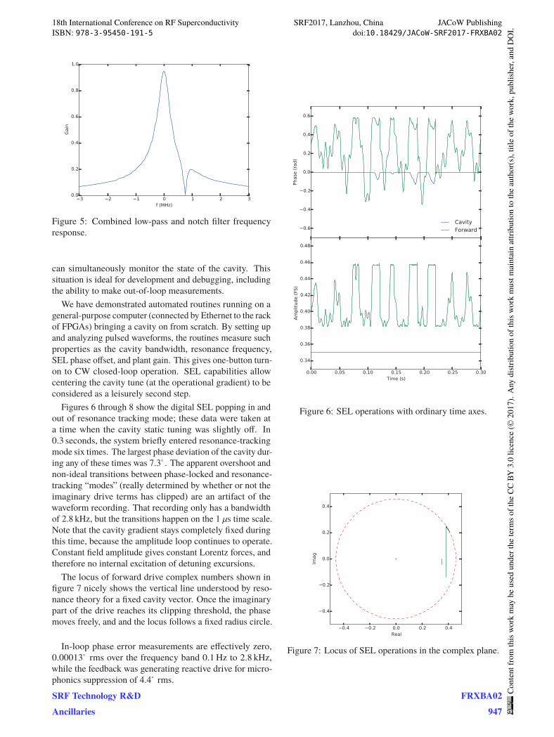
Figure 5: Combined low-pass and notch filter frequency
response.
can simultaneously monitor the state of the cavity. This
situation is ideal for development and debugging, including
the ability to make out-of-loop measurements.
We have demonstrated automated routines running on a
general-purpose computer (connected by Ethernet to the rack
of FPGAs) bringing a cavity on from scratch. By setting up
and analyzing pulsed waveforms, the routines measure such
properties as the cavity bandwidth, resonance frequency,
SEL phase offset, and plant gain. This gives one-button turn-
on to CW closed-loop operation. SEL capabilities allow
centering the cavity tune (at the operational gradient) to be
considered as a leisurely second step.
Figures 6 through 8 show the digital SEL popping in and
out of resonance tracking mode; these data were taken at
a time when the cavity static tuning was slightly off. In
0.3 seconds, the system briefly entered resonance-tracking
mode six times. The largest phase deviation of the cavity dur-
ing any of these times was 7.3◦. The apparent overshoot andnon-ideal transitions between phase-locked and resonance-
tracking “modes” (really determined by whether or not the
imaginary drive terms has clipped) are an artifact of the
waveform recording. That recording only has a bandwidth
of 2.8 kHz, but the transitions happen on the 1 μs time scale.Note that the cavity gradient stays completely fixed during
this time, because the amplitude loop continues to operate.
Constant field amplitude gives constant Lorentz forces, and
therefore no internal excitation of detuning excursions.
The locus of forward drive complex numbers shown in
figure 7 nicely shows the vertical line understood by reso-
nance theory for a fixed cavity vector. Once the imaginary
part of the drive reaches its clipping threshold, the phase
moves freely, and and the locus follows a fixed radius circle.
In-loop phase error measurements are effectively zero,
0.00013◦ rms over the frequency band 0.1Hz to 2.8 kHz,while the feedback was generating reactive drive for micro-
phonics suppression of 4.4◦ rms.
Figure 6: SEL operations with ordinary time axes.
Figure 7: Locus of SEL operations in the complex plane.
18th International Conference on RF Superconductivity SRF2017, Lanzhou, China JACoW PublishingISBN: 978-3-95450-191-5 doi:10.18429/JACoW-SRF2017-FRXBA02
SRF Technology R&DAncillaries
FRXBA02947
Cont
entf
rom
this
wor
km
aybe
used
unde
rthe
term
soft
heCC
BY3.
0lic
ence
(©20
17).
Any
distr
ibut
ion
ofth
isw
ork
mus
tmai
ntai
nat
tribu
tion
toth
eau
thor
(s),
title
ofth
ew
ork,
publ
isher
,and
DO
I.

Figure 8: Connection between cavity and drive phase during
SEL operations.
Figure 9: Out-of-loop phase noise power spectrum density.
Figure 10: Out-of-loop cumulative phase noise.
Figure 11: Prototype Chassis installed at the FNAL CMTS.
Out-of-loop phase error measurements were taken by the
FNAL LLRF system measuring in parallel. Those results
are shown in figure 9; the overall phase error is 0.0016◦ rmsover the frequency band 0.1Hz to 5.0 kHz. A cumulative
plot, integrated up from 0.003Hz, is shown in figure 10. The
FNAL data acquisition system has larger white noise and
crosstalk than the LCLS-II system, and similar 1/ f noise.Consequently, this measurement should be considered an
upper limit, and the actual performance is still unknown. It’s
possible to extrapolate some bench measurements to a cavity
run at -5 dBFS, to get 0.0005◦ rms above 1Hz for a 20 kHzclosed-loop bandwidth, but that is not verified.
Actual cavity field variations in the final accelerator will
necessarily be larger than the noises quoted above. Cable
length variations (including those inside the cryomodule),
beam loading, phase reference line contributions, and the
ever-elusive unknown unknowns will add to the system er-
rors.
The system stability and transient response was checked
for a large number of P and I gain settings, known as a gain
scan. Figure 12 shows one such response.
18th International Conference on RF Superconductivity SRF2017, Lanzhou, China JACoW PublishingISBN: 978-3-95450-191-5 doi:10.18429/JACoW-SRF2017-FRXBA02
FRXBA02948
Cont
entf
rom
this
wor
km
aybe
used
unde
rthe
term
soft
heCC
BY3.
0lic
ence
(©20
17).
Any
distr
ibut
ion
ofth
isw
ork
mus
tmai
ntai
nat
tribu
tion
toth
eau
thor
(s),
title
ofth
ew
ork,
publ
isher
,and
DO
I.
SRF Technology R&DAncillaries

Figure 12: Amplitude loop response to 0.5% setpoint modu-
lation.
RESONANCE CONTROLA low-noise digital-input piezo driver has been built,
tested, and installed in a resonance control chassis, visible
in figure 11 as the chassis second from the top. It (and the
piezo actuator in the cryomodule) has demonstrated the abil-
ity to tune the cavity both statically and dynamically. When
powered on and set to a static value, the detuning noise of
its cavity does not measurably increase, thus verifying that
the design has met system noise goals.
A detuning computer has been incorporated into the cavity
control logic. It tracks the analog state equation to give a
live estimate of the Q and detune frequency of the cavity.
Based on measurements MK and MV of the drive and cavity
vectors, and a complex calibration constant B,
a =1
�MV
·⎡⎢⎢⎢⎢⎣
d �MV
dt− B �MK
⎤⎥⎥⎥⎥⎦
is computed as the exponential coefficient of the cavity equa-
tion; therefore −1/�(a) is the time constant, and �(a) isthe detune frequency in s−1. This equation holds for everyoperating mode of the controller, and is useful as long as
the cavity field measurement is large enough to not suffer
from dividing two very small numbers. Information from the
real part of a may become one source of quench interlock.Detune information will be sent to the resonance control
chassis, initially just for low-frequency correction of helium
pressure drifts.
There are ongoing experiments by Fermilab microphonics
experts to develop DSP code and supporting software that
can actively suppress narrow-band source terms by using the
piezo actuator. The LCLS-II LLRF hardware has the capa-
bility to incorporate that functionality once it is understood.
Stepper motor drivers are also included in the resonance
control chassis. These drivers take special attention because
the motors are cryogenic. Even if microstepping is used
for smoothness of motion, the drive currents have to be set
to zero—implying that the motor is resting on a full-step—
when the motor is not actively moving. The stepper motors
are also essential for parking the tuners in a safe state for
cavity warm-up.
3.9 GHZSixteen 3.9GHz cavities in two cryomodules will also be
part of the final LCLS-II accelerator. These harmonic cavi-
ties are critically important for manipulating the curvature
of the bunches in longitudinal phase space. While the phase
stability requirements have been specified as the same as
given for the 1.3 GHz systems, in time domain this is three
times more stringent.
A 3.9GHz down- and up-conversion strategy has been
planned that shares infrastructure and resources with the
1.3GHz systems. The FPGA and digitizer hardware, and
even the ADC and FPGA clock rates will be identical to
that used in the 1.3GHz systems. A 3920MHz LO will
be used for downconversion to the same 20MHz IF. A
two-stage upconversion process will start with a synthesized
60MHz IF. Frequency triplers will be used to attach the
phase reference line to the PRC reference inputs. Initial
prototypes of these RF chains have shown promising results
in bench tests.
PLANSWith clear evidence from cryogenic cavity tests that the
prototype LCLS-II LLRF system meets critical performance
specifications, the system is ready for its Final Design Re-
view. The system’s production and installation will follow
shortly thereafter. SLAC will lead that effort, with sup-
port from the other collaborating laboratories. During the
system’s checkout and commissioning phase, the technical
responsibilities of each lab within in the collaboration will be
migrated to SLAC via a Lead, Mentor, and Consult transition
plan.
LCLS-II as a whole may not achieve final performance
goals until some time after first light and the transition to
operations. LLRF performance optimization and software
maturation will continue as the operating beam current in-
creases and performance expectations rise.
REFERENCES[1] P. Emma, et al. “Linear Accelerator Design for the LCLS-II
FEL Facility” in Proceedings of FEL2014, Basel, Switzerland
[2] P. Emma “LCLS-II Physics Requirement Document: Linac
Requirements,” LCLSII-2.4-PR-0041-R2.
[3] C. Hovater, L. Doolittle, “The LCLS-II LLRF System,” in
Proceeding of IPAC2015, Richmond, VA, USA, 2015.
[4] L. Doolittle, “Analog-centered LLRF System Design for
LCLS-II,” in Low Level RF workshop 2015, Shanghai, China,October 2015.
[5] G. Huang, K. Campbell, et al. “High Precision RF Controlfor the LCLS-II,” in Proceedings of NAPAC2016, Chicago,IL, October 2016.
18th International Conference on RF Superconductivity SRF2017, Lanzhou, China JACoW PublishingISBN: 978-3-95450-191-5 doi:10.18429/JACoW-SRF2017-FRXBA02
SRF Technology R&DAncillaries
FRXBA02949
Cont
entf
rom
this
wor
km
aybe
used
unde
rthe
term
soft
heCC
BY3.
0lic
ence
(©20
17).
Any
distr
ibut
ion
ofth
isw
ork
mus
tmai
ntai
nat
tribu
tion
toth
eau
thor
(s),
title
ofth
ew
ork,
publ
isher
,and
DO
I.
[6] C. Serrano, L. Doolittle, et al. “LLRF Control of High QL
Cavities for the LCLS-II,” in Proceedings of IPAC2016, Bu-san, Korea, 2016.
[7] L. Doolittle, A. Ratti, et al. “Design of RF Controls for Pre-cision CW SRF Light Sources,” in Low Level RF workshop2013, Lake Tahoe, CA, October 2013.
[8] L. Doolittle, H. Ma, M. S. Champion, “Digital Low-level
RF Control Using Non-IQ Sampling,” in Proceedings ofLINAC2006, Knoxville, TN, August 2006.
[9] G. Huang, L. Doolittle, et al., “Low Noise Digitizer Design
for LCLS-II LLRF,” in Proceedings of NAPAC2016, Chicago,IL, October 2016.
[10] E. Cullerton, B. Chase, “The Design and Performance of the
Fermilab ASTA Phase Averaging 1300MHz Phase Reference
Line” in Low Level RF workshop 2013, Lake Tahoe, CA,October 2013.
[11] J. R. Delayen, “Phase and Amplitude Stabilization of Super-
conducting Resonators,” Ph.D. Thesis, Caltech (1978).
18th International Conference on RF Superconductivity SRF2017, Lanzhou, China JACoW PublishingISBN: 978-3-95450-191-5 doi:10.18429/JACoW-SRF2017-FRXBA02
FRXBA02950
Cont
entf
rom
this
wor
km
aybe
used
unde
rthe
term
soft
heCC
BY3.
0lic
ence
(©20
17).
Any
distr
ibut
ion
ofth
isw
ork
mus
tmai
ntai
nat
tribu
tion
toth
eau
thor
(s),
title
ofth
ew
ork,
publ
isher
,and
DO
I.
SRF Technology R&DAncillaries