High Performance Computing for Non-linear MHD Simulations ... · S. Futatani, PRACEdays18, May...
34
S. Futatani, PRACEdays18, May 29-31, 2018 Page 1 High Performance Computing for Non-linear MHD Simulations for Fusion Plasmas S. Futatani (Universitat de Politècnica de Catalunya) Acknowledgements: G. Huijsmans (CEA), S. Pamela (CCFE), A. Loarte (ITER), M. Hoelzl (IPP) and JOREK Team
Transcript of High Performance Computing for Non-linear MHD Simulations ... · S. Futatani, PRACEdays18, May...

S. Futatani, PRACEdays18, May 29-31, 2018 Page 1
High Performance Computing for Non-linear MHD Simulations for Fusion Plasmas
S. Futatani (Universitat de Politècnica de Catalunya)
Acknowledgements: G. Huijsmans (CEA), S. Pamela (CCFE), A. Loarte (ITER), M. Hoelzl (IPP) and JOREK Team

S. Futatani, PRACEdays18, May 29-31, 2018 Page 2
What makes stars shine?
“The starry night”, V. Willen van Gogh
Can we use the energy of shining stars as an alternative energy source?

S. Futatani, PRACEdays18, May 29-31, 2018 Page 3
What makes stars shine? – Nuclear fusion
E = Dmc2D+T+ He++
n
Nuclear Fusion
U235Nuclear Fission
[nasa.gouv]

S. Futatani, PRACEdays18, May 29-31, 2018 Page 4
Introduction- Plasma / Fusion reactor / ITER Project
Physics background- What is ELM? - JOREK - Nonlinear MHD code
- www.jorek.eu- The JOREK team and themes- Numerical details and physics model- Mechanism of pellet triggered ELM
JOREK Modelling of pellet triggered ELM
Conclusions and Perspectives
Outline

S. Futatani, PRACEdays18, May 29-31, 2018 Page 5
What is plasma?
- Plasma is the 4th state of matter, obtained at high temperature (>105 degrees)- Plasma is an ionized gas which consists of ions and electrons.
For achivement the fusion à Plasma state is needed
[www.nasa.gov]

S. Futatani, PRACEdays18, May 29-31, 2018 Page 6
Galaxy fusion reactor in the universe
[www.setterfird.org] [wikipedia.org]
- In stars: plasma particles are confined mainly by gravity.
è How can we confine the high-temperature plasma? Key parameters for the fusion = high-temperature and high-density

S. Futatani, PRACEdays18, May 29-31, 2018 Page 7
Fusion reactor on Earth
- On Earth: plasmas can be confined in Magnetic field lines = Magnetic Confinement
• Charged particles spiral around magnetic field lines.
• Toroidal (Donut shaped) system avoids plasma hitting the end of the container
è Tokamak
è How can we confine the high-temperature plasma? Key parameters for the fusion = high-temperature and high-density

S. Futatani, PRACEdays18, May 29-31, 2018 Page 8
Fusion plasma reactors in the world
TJ-II (Spain) LHD and JT60U (Japan)
Wendelstein 7-X (Germany)
ITER (international project)
JET (EU) and MAST (UK)
Tokamaks and Stellarators (not listed all here) in the world

S. Futatani, PRACEdays18, May 29-31, 2018 Page 9
What is ITER? [www.iter.org]
ITER is a major international collaboration in fusion energy research involving China, the EU (plus Switzerland), India, Japan, the Russian Federation, South Korea and the United States
ITERITER site (January 2017)
[www.iter.org]

S. Futatani, PRACEdays18, May 29-31, 2018 Page 10
Overview of the ITER Tokamak Pit
Drone view of the tokamak pit and bioshield construction[Figure from Pinches, ITER Organization]
S. Futatani, PRACEdays18, May 29-31, 2018 Page 11
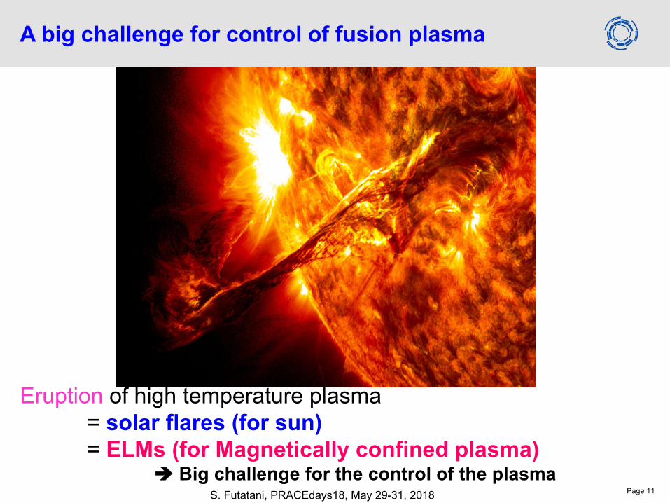
A big challenge for control of fusion plasma
Eruption of high temperature plasma = solar flares (for sun)= ELMs (for Magnetically confined plasma)
è Big challenge for the control of the plasma

S. Futatani, PRACEdays18, May 29-31, 2018 Page 12
Edge Localized Modes (ELMs)
• Fusion plasma has a strong pressure gradient at the plasma boundary.
• Edge pressure gradient is limited by an MHD instability (ballooning mode)• A crash of the edge profile occurs • Release of hot plasmas onto a plasma facing components• ELM removes up to 10% of the plasma energy in ~200 microseconds• Periodic and bursty behaviors
[Figure from Pitts, ITER Organization]
ELM

S. Futatani, PRACEdays18, May 29-31, 2018 Page 13
Edge Localized Modes (ELMs)
Fast camera image of ELM (MAST) [A. Kirk et al.]
• Fusion plasma has a strong pressure gradient at the plasma boundary.
• Edge pressure gradient is limited by an MHD instability (ballooning mode)• A crash of the edge profile occurs • Release of hot plasmas onto a plasma facing components• ELM removes up to 10% of the plasma energy in ~200 microseconds• Periodic and bursty behaviors
ELM

S. Futatani, PRACEdays18, May 29-31, 2018 Page 14
Edge Localized Modes (ELMs)
ELMs lead to a large erosion of and a limited lifetime of the plasma facing components.
• Techniques to control ELM:• stabilisation by external magnetic perturbations• triggered by pellet injection (pellet : deuterium solid ice cube)• Etc…
èRequires physics understanding of ELMs and ELM control
[Linke 2007]

S. Futatani, PRACEdays18, May 29-31, 2018 Page 15
Demonstration of ELM pacing by pellets without fueling
- Pellets can control the ELM frequency- Heat flux of the pellet triggered ELMs on the fusion reactor wall becomes small.
Theoretical and Numerical Modelling studies are needed.
[Baylor APS 2010]Divertor

S. Futatani, PRACEdays18, May 29-31, 2018 Page 16
• JOREK has been developed with the specific aim to simulate ELMs, developed by Dr. G. Huijsmans (CEA/Univ. Eindhoven).
• G.T.A. Huysmans, Plasma Phys. Control. Fusion 47, B165 (2005)• G.T.A. Huysmans and O. Czarny, Nuclear Fusion 47, 659 (2007)• O. Czarny and G. Huysmans, J. Comp. Phys. 16, 7423 (2008)• See [https://www.jorek.eu/]
Non-linear MHD code JOREK

S. Futatani, PRACEdays18, May 29-31, 2018 Page 17
• European Enabling Research Project (PI: M. Hoelzl)• JOREK collaborations (>30 members, >10 international institutions):
• JOREK main development and application• Involved institutes: CEA, IPP Garching, ITER, CCFE, Eindoven, UPC etc.
• Pellet triggering of ELMs / Shattered pellets for disruption• S. Futatani , D. Hu etc.
• ELM mitigation/suppression by external fields• F. Orain, M. Becoulet, K. Wittawat, M. Hoelzl, etc
• Full orbit particle tracer• D. Van vugt, A. Dvornova, C. Somariva, etc.
• Disruptions (MGI, REs, etc)• E. Nardon, C. Sommariva, V. Bandaru, M. Hoelzl, D. Meshcheriakov, F. Wieschollek, etc
• Simulation of ELMs• G. Huijsmans, S. Pamela, M. Becoulet, F. Orain, M. Hoelzl, A. Cathey etc.
• Solvers (PaStiX, HIPS, Interface MURGE)• P. Ramet, P. Henon, X. Lacoste, Univ. Bordeaux/INRIA
• Full MHD model/numerical methods• B. N’Konga, G. Huijsmans, H. Guillard, S. Pamela
• Resistive Wall/Free boundary version (VDEs, RWMs, vertical kicks, ...)• M. Hoelzl, J. Artola-Such, etc
• Numerical methods• B. N’Konga, E. Sonnendruecker, H. Guillard, E. Franck etc
Non-linear MHD code JOREK

S. Futatani, PRACEdays18, May 29-31, 2018 Page 18
• Numerical features:• Discretisation: Xpoint geometry
• Cubic finite elements flux-aligned poloidal grid• Fourier series in toroidal angle
• Time stepping:• fully implicit Crank-Nicholson• Solver sparse matrices (PastiX library) • GMRES iterative solver with physical preconditioner
• Parallelisation using MPI/OPENMP• ~30000 poloidal elements• Typically 1880-3800 cores
• MareNostrum III (BSC), Marconi-Fusion (CINECA), HELIOS-IFERC (Japan), CURIE (France), hydra
(Germany), etc
Non-linear MHD code JOREK
[Provided by M. Hoelzl]
[Provided by S. Pamela]

S. Futatani, PRACEdays18, May 29-31, 2018 Page 19
Non-linear MHD code JOREK• Reduced MHD model (JOREK also has the full MHD model). • Braginskii parallel conductivity• Spitzer resistivity• Mach-1 boundary condition, free flow on divertor target
• Magnetic field and the velocity
• Mass density
• Poloidal momentum (vorticity)
• Parallel momentum
• Temperature
• Poloidal flux
Coupled with the pellet ablation model

S. Futatani, PRACEdays18, May 29-31, 2018 Page 20
Pellet model and implementation in JOREK• Realistic pellet ablation model (NGS model [Gal, NF(2008)]) is implemented in
JOREK : • Pellet moves at fixed speed and direction • Pellet is modelled as an adiabatic localized time-varying density source
Mare Nostrum III in Barcelona
• JOREK simulations have been performed with HELIOS (IFERC-CSC, Japan) and Mare Nostrum (BSC-CNS, Barcelona).
rp: pellet radius [m]ne: plasma electron density [m-3]Te: plasma electron temperature [eV]Sp: Density source
Non-linear MHD physics Pellet ablation physics
JOREK solves a very complex, multi-physics which requires HPCInteractions

S. Futatani, PRACEdays18, May 29-31, 2018 Page 21
Mechanism of pellet triggered ELM

S. Futatani, PRACEdays18, May 29-31, 2018 Page 22
ITER 15MA/5.3T Q=10 plasma
Pedestal pressure leading to spontaneous ELM is 150kPa.
112.5 kPa of the marginal stability limit between stable and unstable.
75 kPa of the pedestal pressure is very stable.
According to the design of future ITER pellet injector, four sizes are studied :
- 4.0x10²¹D , - 3.0x10²¹D, - 2.0x10²¹D, - 1.0x10²¹D
The pellet injection speed is 300m/s.
The pellet injection from Xpoint region is presented.

S. Futatani, PRACEdays18, May 29-31, 2018 Page 23
Plasma dynamics after the pellet injection (example movie of JET plasma)
1.1mm pellet 1.7mm pellet

S. Futatani, PRACEdays18, May 29-31, 2018 Page 24
The time evolution of the plasma energy, for 4.0x10²¹D, 3.0x10²¹D, 2.0x10²¹D, 1.0x10²¹D. The magnetic energies evolution (n=8-10) shows there is a big difference between 4.0x10²¹D and 2.0x10²¹D. à The threshold of the pellet size to trigger an ELM. Need to wait the case of 3.0x10²¹D in order to find the threshold precisely.
Toroidal modes n=8-10 Toroidal modes n=8-10
4.0x10²¹D
3.0x10²¹D
2.0x10²¹D1.0x1021D
ITER plasma – pellet size dependence
4.0x10²¹D
3.0x10²¹D
2.0x10²¹D1.0x1021D

S. Futatani, PRACEdays18, May 29-31, 2018 Page 25
The density plot and the potential contours of the largest pellet 4.0x10²¹Dare shown. The destabilization of the plasma by the pellet injection can be observed.
ITER plasma – pellet size dependence

S. Futatani, PRACEdays18, May 29-31, 2018 Page 26
The maximum values of the sum of the high-n modes (n=6-10) of magnetic energy are plotted as a function of the pellet size.
There is a big difference between 4.0x10²¹Dand 2.0x10²¹D
2.0x10²¹D4.0x1021D
è The threshold of the pellet size to trigger an ELM.
Scaling of non ELM triggering
ITER plasma – pellet size dependence

S. Futatani, PRACEdays18, May 29-31, 2018 Page 27
Toroidally asymmetric heat flux on the divertor target caused by a pellet triggered ELM
This is consistent with the result of JOREK simulation of JET plasma and DIII-D plasma [Futatani, NF 2014; IAEA 2016].

S. Futatani, PRACEdays18, May 29-31, 2018 Page 28
Conclusions• JOREK has been performed to study the non-linear MHD physics. • JOREK allows us to compute the ELM physics and calculate the heat flux onto the
plasma facing components. • Qualitative agreements with the experiment results of JET are observed via
simulation. • The simulations has been performed for ITER size plasma, the results show the
qualitative agreement with JET simulationFuture works• JOREK pellet simulation will be performed including more physics effects to allow for
a more quantitative comparison. • Further development of the optimization of JOREK will be carried out.
JOREK simulationby G. Huijsmans(CEA/ITER)
Conclusions and perspectives

S. Futatani, PRACEdays18, May 29-31, 2018 Page 29
Appendix : What is fusion?
Fission (energy source for these 50 years)
Fusion(it’s going to work… )
E = Dmc2D+
T+He++
U235
n
Advantages of nuclear fusion:(1) Fuel supply is water, therefore no resources problem. (2) Fusion is "cleaner" than fission, i.e. less radioactive by-products. Good for environments.(3) Better control of the nuclear reactions, i.e. fusion can be stoped at any moment by switching off the plasma
Disadvantages of nuclear fusion:-Technical and financial difficulty to achieve…. (Fusion power plant costs a lot…!)-Physics problems (plasma instabilities, plasma control, etc…)

S. Futatani, PRACEdays18, May 29-31, 2018 Page 30
Pellet injection in JET plasma (#84690)The pellet is injected from outer midplane in JET
plasma (#84690).
The pellet injection velocity is 78 m/s.
Four pellet sizes have been investigated (not all
cases are listed here) :
- 1.1mm - 1.7mm
[Frigione et al.,JNM 2015]
Propagation of the pellet cloud Density contour on the last flux surface
The filamentary structures caused by pellet triggered ELM are found.

S. Futatani, PRACEdays18, May 29-31, 2018 Page 31
The density in colour and the heat flux on the divertor target during the spontaneous ELM (without the pellet injection).
The profile of the heat flux on the divertor target is symmetric.
Distribution of the heat flux (by natural ELM)

S. Futatani, PRACEdays18, May 29-31, 2018 Page 32
Distribution of the heat flux (by pellet)
The density in colour and the heat flux on the divertor target during the pellet triggered ELM (1.7mm pellet).
The profile of the heat flux on the divertor target is axymmetric.

S. Futatani, PRACEdays18, May 29-31, 2018 Page 33
Heat flux on the divertor target
Heat flux profile on the divertor target ELM [Wenninger et al. (2010)]. (a) spontaneous ELM (b) pellet triggered ELM
Pellet density source creates another channel to the divertor target.è Distribution of the heat flux in a wide area.
Spontaneous ELM
Pellet triggered ELM (1.7mm)
S. Futatani, PRACEdays18, May 29-31, 2018 Page 34
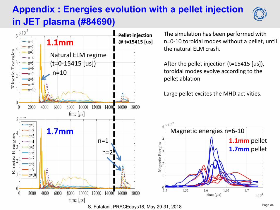
Appendix : Energies evolution with a pellet injection in JET plasma (#84690)
n=10
Pellet injection @ t=15415 [us]1.1mm
1.7mmn=1
n=2
The simulation has been performed with n=0-10 toroidal modes without a pellet, until the natural ELM crash.
After the pellet injection (t=15415 [us]), toroidal modes evolve according to the pellet ablation
Large pellet excites the MHD activities.
Magnetic energies n=6-10
Natural ELM regime (t=0-15415 [us])
1.1mm pellet1.7mm pellet