HIGH PERFORMANCE CARTRIDGE HEATERS · HIGH PERFORMANCE CARTRIDGE HEATERS ... HLPT mit PT 100/NTC /...
32
HLP Hochleistungs-Heizpatronen Cartridge Heaters 9.0
-
Upload
nguyennhan -
Category
Documents
-
view
217 -
download
0
Transcript of HIGH PERFORMANCE CARTRIDGE HEATERS · HIGH PERFORMANCE CARTRIDGE HEATERS ... HLPT mit PT 100/NTC /...
HHLLPPHochleistungs-Heizpatronen
Cartridge Heaters9.0

2
HOCHLEISTUNGSHEIZPATRONENHIGH PERFORMANCE CARTRIDGE HEATERS
Allgemeines / General Informations
Anwendungsgebiete / Applications
Aufbau / Construction
Technische Daten / Technical Data, Grenzwerte / Limit Values
Metrische / inch Typenreihe, Metric dimensions / Imperial sizes
HLP Lagerliste metrisch / Stock type heaters (metric)
HLP Lagerliste inch / Stock type heaters (inch)
Leistungsverteilung / Heated zones
Schaltbare Ausführung / Dual voltage types
HLPT mit Thermoelement / with thermocouple
HLPT mit PT 100/NTC / with PT 100/NTC
PMV leichtverdichtete HLP / lightly compacted HLP
HLPK konische Form / conical shape
HLP für Schutzspannungen / for low voltage
HLPR selbstregelnd / self-regulating
HLPR für Radiatoren / for radiators
für Dehnschrauben / for expansion screws
Anschlussarten / connection types
Einbauhinweise / Advice for the installation
3
3
4
4
5
6 - 9
10
11
11
12
13
14
16
18
20
21
22
24
31

3
ALLGEMEINESGENERAL INFORMATION
ANWENDUNGSGEBIETEAPPLICATIONS
D
E
BeschreibungHochleistungsheizpatronen der Typenreihe HLP sind eine Weiterentwicklung der von uns seit über 50 Jahren hergestellten Heizpatronen konventioneller Bauart.Der spezielle Aufbau ermöglicht eine extrem hohe Oberflächenbelastung und damit die Unterbringung großerLeistung auf kleinstem Raum. Dadurch erschließt dieses Heizelement dem Konstrukteur ein erweitertesAnwendungsgebiet der Elektrowärme.In der DIN 44921 Blatt 2 sind die Durchmesser, die Längen und der Mantelwerkstoff von Hochleistungs heiz -patronen genormt. Unser Angebot umfasst die ganze Normreihe. Die möglichen Durchmesser und Längen gehenweit darüber hinaus.
DescriptionHigh performance cartridge heaters type HLP represent the latest development of cartridge heaters of conventio-nal design which T+H have manufactured for more than 50 years.The special construction renders possible an extremely high surface loading and thus a large power in a smallarea. In this way the element assembly opens an enlarged field of applications for electric heating to the designengineer.DIN 44921, page 2, specifies the standard diameters, lengths and sheath material of high performance cartridgeheaters. Our standard range of high performance cartridge heaters includes all the diameters specified in the DINstandard. As far as length is concerned it includes all those specified in the DIN standard plus many more.
D
E
AnwendungsgebieteKunststoff-Industrie Extrusionsdüsenbeheizungen, Heißkanalverteiler,
Pressformen, Siebwechsel-EinrichtungenSchuhmaschinen-Industrie Vulkanisierpressen und Formenbeheizung, Zwickmaschinen,
HeißprägegeräteGießereien Kernformen und Kokillen, Druckgießmaschinen, Vakuum-OfenbeheizungApparatebau und Labor-Industrie Wärmeplatten, Industriebäder, Destillieranlagen, Lötbäder, Ölsumpfbeheizun-
gen, Sterilisierbäder, ÖlvorwärmerHolzmaschinen-Industrie Heißkleber-, Schmelz- und Auftragegeräte, BrennstempelVerpackungsmaschinen-Industrie Präge-, Siegel- und Schweißstempelbeheizungen,
Kartonverschlussmaschinen, Tubenfüll- und VerschlussmaschinenMedizintechnik Inhaliergeräte und Sterilisatoren, Polymerisationsgeräte, DialysegeräteAllgemeiner Maschinenbau Kleinlufterhitzer, Dehnschraubenbeheizung, Buchbindereimaschinen,
Kältekompressoren
ApplicationsPlastics industry Nozzle heaters for extrusion dies, hot runner systems, filter changing
equipmentShoe machine industry Vulcanising press and mould heating, joining machines, hot stamping
devicesFoundries Core moulds and ingot moulds, die casting machines, vacuum furnace
heatingApparatus construction Hot plates, industrial baths, distillations plants, soldering baths, oil sumpand laboratories heating, sterilising baths, oil economisersWoodworking machinery Hot adhesive - melting- and depositing devices, hot stampingPacking machine industry Stamping- sealing- and welding bar heating, carton closure machine, tube
filling & closure machineryMedical technology Inhaling devices & sterilisers, polymerisation devices, dialysis equipmentGeneral machine construction Small air heater, expansion screw heating, bookbinding machines, cold
compressors

4
E
D
ALLGEMEINE TECHNISCHE DATENGENERAL TECHNICAL DATA
AUFBAUCONSTRUCTION
Anschlussarten: siehe Seite 24 ff.
Unbeheizte Enden: Anschlussende 7-15 mm, Blindende 4-11 mmJe nach Ausführung weitere auf Anfrage
Thermoelement: optional für alle HLP
Mantelwerkstoff: CrNi-Stahl, EN 1.4541/AISI 321
Heizleiter: alle gängigen Heizleiter-Werkstoffe, u.a. NiCr 8020, CuNi 44
Heizleiterträger: reines Magnesiumoxid, hochverdichtet.
Endprüfung: Stückprüfung analog DIN EN 60335-1(VDE 0700)
GrenzwerteSpannung: bis 800 VDurchmesser: metrisch und in Zoll nach Typenliste.Leistung: Minimal- und Maximalwerte sind von den
Patronenabmessungen abhängig.Ableitstrom: < 0,5 mAOberflächenbelast.: bis zu 50 W/cm2 (Mantel)
bei Durchmesser 3 mm, 4 mm und 1/8 inchbis zu 75 W/cm2
Betriebstemperatur: ca. 750°C am Mantelhöhere Temperaturen auf Anfrage
ToleranzenLänge: ±1,5%, mindestens jedoch ±2 mmLeistung: ±10%.
auf Anfrage andere Toleranzen möglich
EConnections: see page 24 continued.
Unheated ends: connection side 7-15 mm; far end 4-11 mm depen-ding on the type, other dimensions upon request.
Thermocouple: optional for all HLP type heaters
Cartridge covering: CrNi-steel, EN 1.4541/AISI 321
Heating conductor: all current heating conductor materials, including NiCr 8020, CuNi 44
Heating conductor Pure magnesium oxide, highly compressedsupport:
Final Test: individual test according to DIN EN 60335 (VDE 0700)
Limit valuesVoltage: up to 800 VDiameters: metric and imperial dimensions see type listCapacity: minimum and maximum values depend on the
dimensions of the cartridgeLeckage current: < 0,5 mASurface load: up to 50 W/cm2 (on the sheath)
at diameter 3 mm, 4 mm and 1/8 inch up to 75 W/cm2
Working temperature: up to 750°C (on the sheath)higher temperatures on request
TolerancesLength: ±1,5%; at least however ±2 mmCapacity: ±10%
other tolerances upon request
DVerdichtete Heizpatronen Typ HLP haben einen Tragkörper, der zentrisch ingeringerem Abstand vom Rohrmantel angeordnet ist.
Der Heizleiter aus der hitzebeständigen Legierung NiCr 8020 ist in einerLage außen um den Tragkörper gewickelt. Der Zwischenraum ist mit rei-nem Magnesiumoxid gefüllt und hochverdichtet.
Die Heizelemente haben einen gas- und flüssigkeitsdicht geschweißtenPatronenboden.
Der Mantel ist spitzenlos auf Fein toleranz geschliffen (Gefüge austenitisch).
Hochleistungsheizpatronen sind auch mit Anschlusslitzen entsprechend denAbbildungen auf S. 24 mit VDE-Zeichen lieferbar.
Compacted cartridge heaters type HLP have a supporting core which is centrally located very close to the outer sheath.
The heating conductor made of the heatproof alloy NiCr 8020 is wound in one layer, around the supporting cores.
The interspace is filled with pure magnesium oxide and is highly compressed.
The bottom end of the cartridge heater is gastight welded; the covering is ground for precision tolerance.
High performance cartridge heaters can also be supplied with VDE approved connection according to the illustrations on page 24.

5
Weitere Durchmesser oder andere Toleranzen auf AnfrageOther diameters or tolerances upon request
Nenn-Durchm. Durchm.-Toleranz max. LängeNominal diameter Diameter tolerance max. length(Inch) (mm) (mm)
1/8 ” 3,10 6000
1/4 ” 6,22 6000
5/16 ” 7,87 6000
3/8 ” 9,40 6000
1/2 ” 12,57 6000
5/8 ” 15,75 6000
3/4 ” 18,93 6000
1 ” 25,28 6000
+0,05+0,02
+0,05
+0,05
+0,05
+0,05
+0,05
+0,05
+0,05
METRISCHE TYPENREIHE METRIC DIMENSIONS
Weitere Durchmesser oder andere Toleranzen auf AnfrageOther diameters or tolerances upon request
INCH-TYPENREIHE IMPERIAL SIZES
Nenn-Durchm. Durchm.-Toleranz max. LängeNominal diameter Diameter tolerance max. length(mm) (mm) (mm)
2,8 2,8 6000
3,0 3,0 6000
4 4 6000
4,5 4,5 6000
5 5 6000
6 6 6000
6,5 6,5 6000
8 8 6000
10 10 6000
12 12 6000
12,5 12,5 6000
13 13 6000
14 14 6000
15 15 6000
16 16 6000
18 18 6000
20 20 6000
22 22 6000
25 25 6000
32 32 6000
-0,01-0,04
-0,01-0,04
-0,01-0,04
-0,01-0,04
-0,01-0,04
-0,02-0,08
-0,02-0,08
-0,02-0,08
-0,02-0,08
-0,02-0,08
-0,02-0,08
-0,02-0,08
-0,02-0,08
-0,02-0,08
-0,02-0,08
-0,02-0,08
-0,02-0,08
-0,02-0,08
-0,02-0,08
-0,02-0,08

6
LAGERLISTE METRISCHSTOCK TYPE HEATERS
HinweisDie ab Lager lieferbaren kleinen Hochleistungsheiz- patronen mit den Durchmessern 3,0, 3,1 (1/8“), 4 und 5mm sind alle mit flexibel herausgeführten, teflonisoliertenLitzen (LETEF) mit einer Anschlusslänge von 1000 mmversehen.
Please noteThe small high performance cartridge heaters with diameter 3.0, 3.1 (1/8“), 4 and 5 mm will be supplied exstock with flexible PTFE-insulated leads (LETEF) with alength of 1000 mm.
Belastungsgruppen Oberflächenbelastung W/cm2
Load groups Surface load W/cm2
I 8 … 11II 12 … 19III 20 … 24IV 25 … 29V 30 … 35

7
METRISCHE AUSFÜHRUNG METRIC DIMENSIONS
Ø
mm
4-0,01-0,04
3,0-0,01-0,04
5-0,01-0,04
Ø 3
Ø 4
Länge Leistung Gruppe Artikel Length Power Group Article
bei/at 230 V
L Watt W/cm2 Nr./No.
30 50 IV 12120030 80 > V 121201
40 40 II 12120240 50 II 12120340 80 IV 12120440 100 > V 121205
50 50 II 12120650 60 II 12120750 100 IV 12120850 125 V 121209
60 60 II 12121060 80 II 12121160 125 IV 12121260 160 V 121213
40 30 I 12112040 60 II 12112140 100 IV 12112240 125 V 12112340 160 > V 121124
50 40 I 12112550 80 II 12112650 125 IV 12112750 160 V 12112850 200 > V 121129
60 50 I 12113060 100 II 12113160 140 III 121132
Ø 5
60 180 IV 12113360 220 > V 121134
80 60 I 12113580 125 II 12113680 180 III 12113780 220 IV 12113880 280 V 121139
40 40 I 12114040 80 II 12114140 125 V 12114240 160 > V 12114340 200 > V 121144
50 50 I 12114550 100 II 12114650 140 III 12114750 180 V 12114850 220 > V 121149
60 60 I 12115060 125 II 12115160 160 III 12115260 200 IV 12115360 250 V 121154
80 80 I 12115580 140 II 12115680 180 II 12115780 220 III 12115880 280 IV 121159
100 100 I 121160100 160 II 121161100 200 II 121162100 250 II 121163100 315 III 121164
INCH AUSFÜHRUNG IMPERIAL DIMENSIONS
Ø
inch
1/8+0,05 mm +0,02 mm
Ø 1/8
Länge Leistung Gruppe Artikel Length Power Group Article
bei/at 230 V
L Watt W/cm2 Nr./No.
30 50 IV 12110030 80 > V 121101
40 40 II 12110240 50 II 12110340 80 IV 12110440 100 > V 121105
50 50 II 12110650 60 II 12110750 100 IV 12110850 125 V 121109
60 60 II 12111060 80 II 12111160 125 IV 12111260 160 V 121113
NEU !

8
LAGERLISTE METRISCHSTOCK TYPE HEATERS
METRISCHE AUSFÜHRUNG METRIC DIMENSIONS
Lagerware kann kurzfristig mit verschiedenen Anschlüssen(ab Seite 24) konfektioniert werden.
Heaters ex-stock can also be supplied complete withaccessories (see page 24 cont.) at short notice.
HinweisDie Bestellnummern für Artikel mit isoliertem AnschlussTyp ISAN sind 125xxx statt 120xxx.
Please noteThe order numbers for articles with insulated connectiontype ISAN are 125xxx instead of 120xxx.
Ø
mm
8-0,02 -0,08
6,5-0,02 -0,08
10-0,02 -0,08 Ø 6,5
Ø 8
Ø 10
Länge Leistung Gruppe Artikel Length Power Group Article
bei/at 230 V
L Watt W/cm2 Nr./No.
40 100 II 120 000125 III 120 001160 IV 120 002175 IV 120 003200 V 120 004
50 100 II 120 005160 III 120 006200 IV 120 007250 V 120 008
60 125 II 120 009200 III 120 010250 IV 120 011315 V 120 012
80 125 I 120 013180 II 120 014280 III 120 015350 IV 120 016
100 160 I 120 017220 II 120 018350 III 120 019
40 100 II 120 020160 III 120 021200 IV 120 022250 V 120 023
50 125 II 120 024200 III 120 025250 IV 120 026315 V 120 027
60 100 I 120 028140 II 120 029220 III 120 030280 IV 120 031350 V 120 032
80 160 I 120 033200 II 120 034315 III 120 035400 IV 120 036
100 180 I 120 037280 II 120 038400 III 120 039
130 250 I 120 040400 II 120 041
40 100 I 120 042125 II 120 043200 III 120 044250 IV 120 045315 V 120 046
50 100 I 120 047160 II 120 048250 III 120 049315 IV 120 050400 V 120 051
60 125 I 120 052180 II 120 053315 III 120 054400 IV 120 055500 V 120 056
80 160 I 120 057250 II 120 058400 III 120 059500 IV 120 060630 V 120 061
100 220 I 120 062350 II 120 063560 III 120 064700 IV 120 065850 V 120 066
130 315 I 120 067500 II 120 068800 III 120 069
160 400 I 120 070630 II 120 071
Belastungsgruppen Oberflächenbelastung W/cm2
Load groups Surface load W/cm2
I 8 … 11II 12 … 19III 20 … 24IV 25 … 29V 30 … 35

9
METRISCHE AUSFÜHRUNG METRIC DIMENSIONS
16-0,02 -0,08
20-0,02 -0,08
Ø 20
Ø 12,5
Ø 16
Länge Leistung Gruppe Artikel Length Power Group Article
bei/at 230 V
L Watt W/cm2 Nr./No.
40 100 I 120 072160 II 120 073250 III 120 074315 IV 120 075400 V 120 076
50 100 I 120 077200 II 120 078315 III 120 079400 IV 120 080500 V 120 081
60 125 I 120 082200 II 120 083315 III 120 084400 IV 120 085500 V 120 086
80 200 I 120 087315 II 120 088500 III 120 089630 IV 120 090800 V 120 091
100 250 I 120 092400 II 120 093630 III 120 094800 IV 120 095
1000 V 120 096
130 400 I 120 097630 II 120 098
1000 III 120 0991250 IV 120 100
160 500 I 120 101800 II 120 102
1250 III 120 103
200 630 I 120 104900 II 120 105
40 100 II 120 106250 III 120 107315 IV 120 108400 V 120 109
50 160 I 120 110250 II 120 111400 III 120 112500 IV 120 113630 V 120 114
60 160 I 120 115250 II 120 116400 III 120 117500 IV 120 118630 V 120 119
80 280 I 120 120400 II 120 121630 III 120 122800 IV 120 123
1000 V 120 124
100 350 I 120 125500 II 120 126800 III 120 127
1000 IV 120 1281250 V 120 129
130 500 I 120 130700 II 120 131
1100 III 120 1321400 IV 120 1331800 V 120 134
160 630 I 120 135900 II 120 136
1600 III 120 1371800 IV 120 138
200 800 I 120 1391250 II 120 1402000 III 120 141
250 1000 I 120 1421600 II 120 143
300 1250 I 120 1441800 II 120 145
60 200 I 120 146315 II 120 147500 III 120 148630 IV 120 149800 V 120 150
80 350 I 120 151500 II 120 152800 III 120 153
1000 IV 120 1541250 V 120 155
100 450 I 120 156630 II 120 157
1000 III 120 1581400 IV 120 1591600 V 120 160
130 630 I 120 161900 II 120 162
1400 III 120 1631800 IV 120 1642200 V 120 165
160 800 I 120 1661100 II 120 1671800 III 120 1682200 IV 120 169
200 1000 I 120 1701600 II 120 1712500 III 120 172
250 1250 I 120 1732000 II 120 174
300 1600 I 120 1752200 II 120 176
12,5-0,02 -0,08
Ø
mm

10
LAGERLISTE (ZOLL)STOCK TYPE HEATERS (INCH)
INCH AUSFÜHRUNG IMPERIAL DIMENSIONS
1/4+0,05 mm
5/16+0,05 mm
1/2+0,05 mm
5/8+0,05 mm
3/8+0,05 mm
Ø 1/4
Ø 5/16
Ø 3/8
Ø 5/8
Länge Leistung Gruppe Artikel Lenght Power Group Article
bei/at 230 VInch Watt W/cm2 Nr./No.
1 1/2 100 II 125 179125 III 125 180160 IV 125 181175 IV 125 182200 V 125 183
2 100 II 125 184160 III 125 185200 IV 125 186250 V 125 187
2 1/2 125 II 125 188200 III 125 189250 IV 125 190315 V 125 191
3 1/4 125 I 125 192180 II 125 193280 III 125 194350 IV 125 195
4 160 I 125 196220 II 125 197350 III 125 198
1 1/2 100 II 125 199160 III 125 200200 IV 125 201250 V 125 202
2 125 II 125 203200 III 125 204250 IV 125 205315 V 125 206
2 1/2 100 I 125 207140 II 125 208220 III 125 209280 IV 125 210350 V 125 211
3 1/4 160 I 125 212200 II 125 213315 III 125 214400 IV 125 215
4 180 I 125 216280 II 125 217400 III 125 218
5 1/4 250 I 125 219400 II 125 220
1 1/2 100 I 125 221125 II 125 222200 III 125 223250 IV 125 224315 V 125 225
2 100 I 125 226160 II 125 227250 III 125 228315 IV 125 229400 V 125 230
2 1/2 125 I 125 231180 II 125 232315 III 125 233400 IV 125 234500 V 125 235
3 1/4 160 I 125 236250 II 125 237400 III 125 238500 IV 125 239630 V 125 240
4 220 I 125 241350 II 125 242560 III 125 243700 IV 125 244850 V 125 245
5 1/4 315 I 125 246500 II 125 247800 III 125 248
6 1/2 400 I 125 249630 II 125 250
Ø 1/21 1/2 100 I 125 251
160 II 125 252250 III 125 253315 IV 125 254400 V 125 255
2 100 I 125 256200 II 125 257315 III 125 258400 IV 125 259500 V 125 260
2 1/2 125 I 125 261200 II 125 262315 III 125 263400 IV 125 264500 V 125 265
3 1/4 200 I 125 266315 II 125 267500 III 125 268630 IV 125 269800 V 125 270
4 250 I 125 271400 II 125 272630 III 125 273800 IV 125 274
1000 IV 125 275
5 1/4 400 I 125 276630 II 125 277
1000 III 125 2781250 IV 125 279
6 1/2 500 I 125 280800 II 125 281
1250 III 125 282
8 630 I 125 283900 II 125 284
1 1/2 100 II 125 285250 III 125 286315 IV 125 287400 V 125 288
2 160 I 125 289250 II 125 290400 III 125 291500 IV 125 293
2 1/2 160 I 125 294250 II 125 295400 III 125 296500 IV 125 297630 V 125 298
3 1/4 280 I 125 299400 II 125 300630 III 125 302
1000 V 125 303
4 350 I 125 304500 II 125 305800 III 125 306
1000 IV 125 3071250 V 125 308
5 1/4 500 I 125 309700 II 125 310
1100 III 125 3111400 IV 125 3121800 V 125 313
6 1/2 630 I 125 314900 II 125 315
1600 II 125 3161800 IV 125 317
8 800 I 125 3181250 II 125 3192000 III 125 320
10 1000 I 125 3211600 II 125 322
12 1250 I 125 3231800 II 125 324
ØInch

11
LEISTUNGSVERTEILUNGHEATED ZONES
StandardausführungStandard heat distribution
Unbeheizte Zone am Anschluss und/oder BlindendeUnheated zone on connection side and/or far end
Anfang und/oder Ende stärker beheiztReinforced power distribution on one or both ends
Mitte unbeheiztUnheated in the middle of the heater
SCHALTBARE AUSFÜHRUNGENDUAL VOLTAGE TYPES
Ausführung 1 (2 Schaltzonen / 3 Anschlussleitungen)Version 1 (2 switchable zones / 3 connection leads)
Ausführung 3 (3 Schaltzonen / 4 Anschlussleitungen)Version 3 (3 switchable zones / 4 connections leads)
Ausführung 2 (2 Schaltzonen / 4 Anschlussleitungen)Version 2 (2 switchable zones / 4 connection leads)
● generell für alle HLP und HLP/T● nicht ab Lager lieferbar
● possible for all HLP and HLP/T type heaters● not available ex-stock
● ermöglicht getrennte Beheizungeinzelner Zonen
● nicht ab Lager lieferbar
● allows separate heating of zones ● not available ex-stock

12
Durchmesser Länge Leistung (W) Artikel-Nr.Diameter Length Power (W) Article-No.
bei/at 230 V
6,5 mm 40 mm 100 120 900
50 mm 200 120 905
100 mm 350 120 910
10,0 mm 40 mm 200 120 915
50 mm 250 120 920
60 mm 400 120 925
80 mm 250 120 930
160 mm 400 120 935
1/4“ 1 1/2“ 100 120 950
2“ 200 120 955
4“ 350 120 960
3/8“ 1 1/2“ 200 120 965
2“ 250 120 970
2 1/2“ 315 120 975
3 1/4“ 400 120 980
4“ 350 120 985
LAGERLISTE STOCK TYPE HEATERS
HLP T mit TE/with TC
HLP T MIT THERMOELEMENTHLP T WITH THERMOCOUPLE
DE
AllgemeinesAlle HLP sind mit Thermoelement lieferbar. Die in der Tabelle aufgeführtenHochleistungsheizpatronen erhalten Sie direkt ab Lager. Hochleistungs -heizpatronen mit fest eingebautem Thermoelement sind speziell für innen-beheizte Düsen und beheizte Torpedos geeignet, wo aus Platzgründen keinseparater Temperaturfühler in dem Werkstück untergebracht werden kann.Das Thermoelement ist eingepasst und potentialfrei isoliert vom Manteloder alternativ mit dem Mantel verbunden.
General informationAll HLP type heaters can be supplied with an integrated thermocouple.Heaters mentioned in the table are available ex-stock. High performancecartridge heaters are especially suitable for internally heated nozzles andheated torpedos where, due to space considerations, a separate thermo-couple cannot be installed. The thermocouple is fixed in position, compac-ted and potential free insulated from the sheath or alternatively connectedwith the heater sheath.
AusführungDie angeschlossenden Ausgleichsleitungen werden in Längen nachWunsch hergestellt. Das Thermoelement ist, wenn bei der Bestellung nichtanders vereinbart, vom Patronenmantel galvanisch getrennt. Auf Wunschkönnen Heizpatronen Typ HLPT auch mit elektr. Verbindung zwischenThermoelement und Patronenmantel geliefert werden.
ExecutionCompensating leads can be connected to specified requirements. The thermocouple is galvanically separated from the cartridge sheathunless otherwise specified at the time of ordering. HLPT can also be supplied with an electrical connection between the thermocouple and the cartridge sheath, if so desired.
Kurzzeichen des Fe-Konst (Fe-CuNi) NiCr-NiThermopaares DIN 43713 DIN 43713
Abbreviated designationof thermocouple
Plusschenkel Eisen Nickel-Chromplus leg Iron Nickel-Chromium
Minusschenkel Konstantan Nickelminus leg Constantan
Messtemperatur Grundwerte zul. Abweich. Grundwerte zul. Abweich.Measuring temperature Basic values permissible deviation Basic values permissible deviation
°C mV K % mV K %
0 0 - - 0 - -
100 5,37 4,10
200 10,95 3 - 8,13 3
300 16,56 12,21
400 22,16 16,40
500 27,85 20,65
600 33,67 - 0,75 24,91 - 0,75
700 29,14
zulässige Abweichungen in K bzw. in % bezogen auf die Messtemperatur. Bezugstemperatur 0°C.
permissible deviation in K or in % related from the measuring temperature. Reference temperature 0°C.
-0,02 mm -0,08 mm
-0,02 mm -0,08 mm
+0,05 mm
+0,05 mm

D EAllgemeinesAlle HLP sind mit einem integrierten Platin-Temperatur-Sensor nach DIN EN 60751 (PT 100) oder mit einem integrierten NTC-Sensor (Negative Temperature Coefficient) zur präzisen Temperaturmessung lieferbar. Sie werden vorzugsweise in den Branchen Automobil, weißeWare, Klima- und Heizungstechnik sowie in Geräten und Maschinen fürMedizin und Industrie eingesetzt.
Vorteile- hohe Genauigkeit über einen großen Temperaturbereich- Langzeitstabilität- Werkstoff der Anschlussleitungen beliebig
wählbar im Gegensatz zu Thermoelementen
General informationAll HLP type heaters can be manufactured with an integrated temperaturesensor i.a.w. DIN EN 60751 (PT 100) or with an integrated NTC-sensor(negative temperature coefficient) for precise temperature measurement.Typical fields of application therefore are within the car industry, electro-domestical appliances, air conditioning devices, for general machineryand medical technique appliances.
Advantages- High precision over a wide temperature range- High reliability- Materials of the connection leads can be freely
chosen other than for thermocouple wires
EDTechnical DataConstructionAs per the types HLP butThermocoupleType J, Type K Color coding according to customer requirements
(IEC 584, DIN 43713, ANSI/MC 96.1)Cartridge diameterHigh performance heating elements type HLPT can be supplied in diame-ters from 4,0 to 32 mm and in the corresponding imperial dimensions.
Type listThe stock type heaters are equipped with a Fe-CuNi-thermocouple andleads with PTFE insulation type LETEF and compensation leads typeLEAUS both with a length of 1000 mm.Other lengths on request.
Please noteDiameter Ø 2.8, Ø 3.0 and Ø 1/8" are also available as HLPT,but only with a connection sleeve.
13
Technische DatenAufbau Wie Hochleistungsheizpatronen, Typ HLP, jedochThermoelementTyp J, Typ K Farbkennzeichnung nach Kundenwunsch
(IEC 584, DIN 43713, ANSI/MC 96.1)PatronendurchmesserHochleistungsheizelemente Typ HLPT sind in den Durchmessern 4,0 mm bis32 mm und entsprechenden Durchmessern in Zollabmessungen lieferbar.
TypenlisteDie ab Lager erhältlichen HLPT sind in Fe-CuNi-Ausführung und mit Anschlusslitzen Typ LETEF sowie Ausgleichsleitung Typ LEAUS konfektioniert. Länge LETEF/LEAUS 1000 mm.Andere Längen auf Anfrage.
HinweisDurchmesser Ø 2,8, Ø 3,0 und Ø 1/8” sind auch als HLPT lieferbar, jedoch nur mit einer Anschlusshülse.
HinweisLieferbar ab Durchmesser 4 mm
Please noteAvailable from diameter 4 mm
Integriertes ThermoelementIntegrated thermocouple
Thermoelement am PatronenendeThermocouple at the end of the cartridge heater
Thermoelement mittig isoliertThermocouple insulated
Thermoelement am Patronenende isoliertThermocouple insulated at the bottom end
HLP T MIT PT 1000/PT 100/NTCHLP T WITH PT 1000/PT 100/NTC

14
TYP PMV (LEICHTVERDICHTET)TYPE PMV (LIGHTLY COMPACTED)
D
E
EigenschaftenDie leichtverdichteten Heizkörper dieser Typenreihe zeichnen sich gegen überunverdichteten Metallmantelpatronen bei gleicher Oberflächenbelastungdurch höhere Beständigkeit gegenüber mechanischen Einflüssen und durcheine wesentlich höhere Lebensdauer aus. Sie eignen sich zur Beheizungflüssiger, gasförmiger und fester Medien und sind selbst rauhestenBetriebsbedingungen im industriellen Bereich gewachsen.
Technische Datenwie Hochleistungsheizpatronen Typ HLP, jedoch:
max. Oberflächenbelastung ca. 6,5 W/cm2
Toleranzen Durchmesser: +0,2 mm bei ungeschliffenem Manteloptional mit Feintoleranz -0,02 mm bis-0,08 mm geschliffen
Länge: ±1,5%, mindestens jedoch ±2 mm.Leistung: ±10%
HinweisDer Typ PMV wird nicht außerhalb der Lagertypen gefertigt.
CharacteristicsThe lightly compacted cartridge heaters of this series distinguish themselvesby a higher immunity against mechanical shock, and by a substantially longer useful life as compared with noncompacted metal sheathed cartridgeheaters of the same surface load. They are suitable for heating liquids,gaseous and solid media and resist arduous service conditions in industrialapplications.
Technical Datasimilar to the high performance cartridge heaters type HLP, however:
Maximum surface load: approx. 6,5 W/cm2 (on the sheath)Tolerances: Diameter: +0,2 mm of the groundless covering.
Upon request these can be ground to finer tolerances -0,02 to 0,08 mm
Length: ±1.5% at least, however ±2 mmCapacity: ±10%
Please noteCartridge heaters type PMV are only produced in stock types.
15
LAGERLISTE STOCK TYPE HEATERS
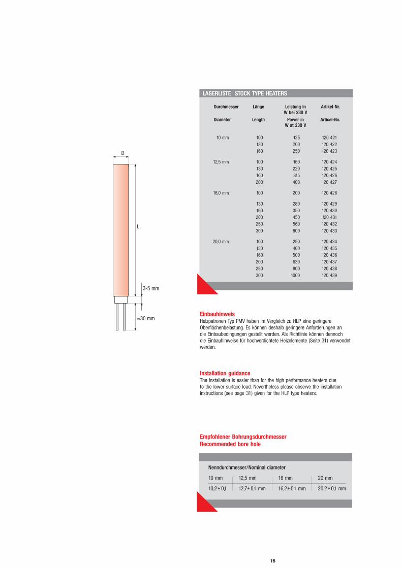
Durchmesser Länge Leistung in Artikel-Nr.W bei 230 V
Diameter Length Power in Articel-No.W at 230 V
10 mm 100 125 120 421130 200 120 422160 250 120 423
12,5 mm 100 160 120 424130 220 120 425160 315 120 426200 400 120 427
16,0 mm 100 200 120 428
130 280 120 429160 350 120 430200 450 120 431250 560 120 432300 800 120 433
20,0 mm 100 250 120 434130 400 120 435160 500 120 436200 630 120 437250 800 120 438300 1000 120 439
Nenndurchmesser/Nominal diameter
10 mm 12,5 mm 16 mm 20 mm
10,2+ 0,1 12,7+ 0,1 mm 16,2+ 0,1 mm 20,2+ 0,1 mm
EinbauhinweisHeizpatronen Typ PMV haben im Vergleich zu HLP eine geringereOberflächenbelastung. Es können deshalb geringere Anforderungen an die Einbaubedingungen gestellt werden. Als Richtlinie können dennoch die Einbauhinweise für hochverdichtete Heizelemente (Seite 31) verwendetwerden.
Installation guidanceThe installation is easier than for the high performance heaters due to the lower surface load. Nevertheless please observe the installationinstructions (see page 31) given for the HLP type heaters.
Empfohlener Bohrungsdurchmesser Recommended bore hole

16
KONISCHE FORM, TYP HLPKCONICAL SHAPE, TYPE HLPK
AnwendungsgebieteGießbehälterbeheizung, Formenbeheizung, Siegelbackenbeheizung,Zigarettenmaschinen, Schuhmaschinen, Brennstempel.
Ein- und AusbauhinweiseDas Werkstück wird mit einer der konischen Form der Patrone ent -sprechenden Sack- oder Durchgangsbohrung versehen.Passende Werkzeuge (Bohrer und Reibahlen) sind ab Lager erhältlich.
Auch für die HLPK empfehlen wir die Verwendung des hochtemperatur -beständigen Montagegleitmittels VARYBOND REGULAR GRADE.
Beim Ausbau der Patrone erleichtert das spezielle Ausziehwerkzeug (Art.-Nr. 600090) den Ausziehvorgang und schont Werkstück und Patrone.Auswechseln bei Durchgangsbohrungen durch Konterschlag auf denPatronenboden.
ApplicationsHeating of founding tanks, die- and mold making, cigarette-machines,machines for shoe production.
Installation hintsThe workpart is provided with a pass or a blind bore according to the cartridge heater. Suitable tooling is available ex-stock.
We recommend the usage of the high temperature resistant lubricantVARYBOND REGULAR GRADE.
The disassembly of the cartridge heater is especially simplified by its coni-cal sheath shape. A special pull out tool (Art No. 600090) facilitates thepull off process and preserves the workpiece and the cartridge heaterfrom being damaged.
D
E
EigenschaftenDer Typ HLPK besitzt einen konischen Außenmantel im Kegelverhältnis1:50 nach DIN 1 für genormte Kegelstifte.Die konische Patronenform gewährleistet passgenauen Presssitz im Werk -stück. Selbst im Falle zu stark ausgeriebener Bohrungen ist noch eine hervorragende Passung vorhanden, da die Patrone in diesem Fall lediglicheine geringfügig tiefere Einbauposition einnimmt. Durch die exakte Pas sungergibt sich auch eine ausgezeichnete Wärmeableitung und somit wenigerGefahr der Überhitzung der Patrone. Zur Erzielung eines gleich mäßigenTemperaturprofils ist dieser Patronentyp an beiden Enden mit angehobenenLeistungszonen ausgestattet.
CharacteristicsThe high performance cartidge heater type HLPK has a conically taperedsheath with a taper ratio 1:50 i.a.w. DIN 1 for standard taper pins.The conical shape of the cartridge heater guarantees an exact force fit in the workpiece. In the case of accurately reamed bores, there is anexcellent fit, as the cartridge heater in this case takes a slightly deeperinstallation depth.An excellent heat distribution results from the exact fit and, thus, the danger of overheating the cartridge heater is kept low. In order to get an even temperature profile, the cartridge heaters type HLPK are equippedwith reinforced performance zones on both sides.
Kegel/taper 1:50

17
TECHNICAL DATA
LAGERLISTE STOCK
Länge Leistung in Watt bei 230 V Artikel-Nr.Length Power in Watt at 230 V Article-No.
60 160 121 000250 121 001
80 250 121 004400 121 005
100 250 121 008400 121 009
130 315 121 012500 121 013800 121 014
160 400 121 017630 121 018800 121 019
Bohrer, konisch 12,5 x 180 785 005Twist drill, conical
Reibahle, konisch 12,5 x 200 785 006Reamer, conical
Ausziehwerkzeug 600 075Pull-out tool
Connections: glass fibre insulated leads fastened fromoutside, standard lengths 250, 500, 800 or 1000 mm
Executions: with or without threaded ring M 20 x 1,5 as disassembly aid
Leakage current: max. 0,5 mATest: tested according to VDE 0721
TECHNISCHE DATEN
Anschlüsse: außen angeschlagene glasseidenisolierte Litzen in den Standardlängen250, 500, 800 oder 1000 mm
Ausführung: mit oder ohne GewinderingM 20 x 1,5 als Ausbauhilfe
Ableitstrom: max. 0,5 mAPrüfung: geprüft nach VDE 0721
Bohrer und Reibahle, konischTwist drill and reamer, conical
AusziehwerkzeugPull-out tool
D
EDiameter: far end 12,5 mm,
connection end from 13,7 to 15,7 mmTaper ratio: 1:50Length: according to type list 60-160 mmPower: according to type list, tolerance 10%Voltage: 230 VSheath of the cartridge: CrNi-steel,
material no. 1.4541 (AISI 321), max. allowable sheath temperature 750°C.
Durchmesser: Blindende 12,5 mmAnschlussende von 13,7 bis 15,7 mm
Kegelverhältnis: 1:50Länge: nach Typenliste 60-160 mmLeistung: nach Typenliste Toleranz 10%Spannung: 230 VPatronenmantel: CrNi-Stahl X 10 CrNiTi 18-10
Werkst. 1.4541max. zul. Manteltemperatur 750°C

18
HLP FÜR SCHUTZSPANNUNGENHLP FOR LOW VOLTAGES
D
E
AllgemeinesDiese hochverdichteten Heizelemente wurden vor allem zur Beheizungkleinster Teile entwickelt. Der Außenmantel besteht aus Chrom-Nickel-Stahl, Werkstoff-Nr. 1.4541. Er dient als Rückleiter. Die Hochleistungsheiz -patronen Typ HLP 2,8, HLP 4,5 und HLP 5 dürfen deshalb nur für denBetrieb bei Schutzspannungen bis max. 42 V verwendet werden.
Technische BeschreibungDer Mantel der Heizpatronen für Schutzspannungen ist ungeschliffen(Durchmesser 2,8 - 0,1 mm, 4,5 ±0,1 mm, bzw. 5 ±0,1 mm). Der Bodenist gas- und flüssigkeitsdicht eingeschweißt. Die maximale Mantel-temperatur der Heizelemente beträgt bei den Durchmessern 2,8 und 4,5ca. 500°C und bei den Patronen mit Durchmesser 5,0 mm ca. 750°C. DerAnschluss besteht bei den Kleinspannungsheizpatronen mit Durchmesser2,8 und 4,5 mm aus einem ca. 100 mm langen Verdrillende, das mitTeflonschlauch isoliert ist. Die Temperaturbeständigkeit desTeflonschlauches beträgt kurzfristig 300°C, dauerhaft 250°C. Bei denHeizelementen mit Durchmesser 5,0 mm besteht der Anschluss aus einemca. 20 mm langen glatten Bolzen mit Durchmesser 2 mm.
General InformationThese highly compacted heating elements have been developed primarilyfor the heating of small parts. The sheath is made of chrome-nickel steel,material no. 1.4541 and serves as a return conductor. Therefore the highperformance cartridge heaters type HLP 2.8; HLP 4.5 and HLP 5.0 mayonly be used for operation at low voltages up to 42 V max.
Technical DataThe sheath of the cartridge heaters for low voltages is not ground (diame-ter 2.8 mm -0.1 mm; 4.5 mm ±0.1 mm and 5.0 mm ±0.1 mm) . The bot-tom end is welded gas and liquid tight. The maximum sheath temperaturefor the Ø 2.8 mm and Ø 4.5 mm heaters is approx. 500°C and 750°C forthe Ø 5.0 mm cartridges. The connection cable for the low voltage cartrid-ge heater with diameter 2.8 and 4.5 mm consists of a 100 mm long twi-sted wire which is insulated by a teflon hose. The teflon insulation canwithstand temperatures up to 300°C at short time use and 250°C for permanent use. The connection end of the Ø 5.0 mm heating elementsconsists of a Ø 2 mm connection bolt with a length of 20 mm.
19
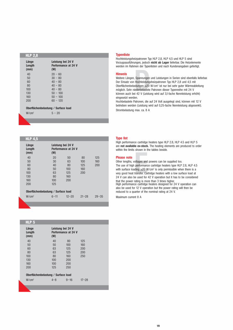
HLP 2,8
Länge Leistung bei 24 VLength Performance at 24 V(mm) (W)
40 20 – 6050 30 – 8060 40 – 8080 40 – 80
100 40 – 80130 50 – 100160 50 – 100200 60 – 120
Oberflächenbelastung / Surface load
W/cm2 5 – 20
HLP 4,5
Länge Leistung bei 24 VLength Performance at 24 V(mm) (W)
40 20 50 80 12550 30 63 100 16060 40 80 125 20080 50 100 160
100 63 125 200130 80 160160 100 200200 125
Oberflächenbelastung / Surface load
W/cm2 6–11 12–20 21–28 29–35
HLP 5
Länge Leistung bei 24 VLength Performance at 24 V(mm) (W)
40 40 80 12550 50 100 16060 63 125 20080 63 125 200
100 80 160 250130 100 200160 100 200200 125 250
Oberflächenbelastung / Surface load
W/cm2 4–8 9–16 17–28
D
E
TypenlisteHochleistungsheizpatronen Typ HLP 2,8, HLP 4,5 und HLP 5 sindVorzugsausführungen, jedoch nicht ab Lager lieferbar. Die Heizelemente werden im Rahmen der Typenlisten und nach Kundenangaben gefertigt.
HinweisWeitere Längen, Spannungen und Leistungen in Serien sind ebenfalls lieferbar.Der Einsatz von Hochleistungsheizpatronen Typ HLP 2,8 und 4,5 mitOberflächenbelastungen ≥20 W/cm2 ist nur bei sehr guter Wärmeableitungmöglich. Sehr niederbelastete Patronen dieser Typenreihe mit 24 V können auch bei 42 V (Leistung wird auf 3,1-fache Nennleistung erhöht) eingesetzt werden.Hochbelastete Patronen, die auf 24 Volt ausgelegt sind, können mit 12 Vbetrieben werden (Leistung wird auf 0,25-fache Nennleistung abgesenkt).
Strombelastung max. ca. 8 A
Type listHigh performance cartridge heaters type HLP 2.8, HLP 4.5 and HLP 5 are not available ex-stock. The heating elements are produced to orderwithin the limits shown in the tables beside.
Please noteOther lengths, voltages and powers can be supplied too.The use of high performance cartridge heaters type HLP 2.8, HLP 4.5 with surface loading ≥20 W/cm2 is only permissible when there is a very good heat transfer. Cartridge heaters with a low surface load at 24 V can also be used for 42 V operation but it has to be considered that the power rating is more than 3 times higher.High performance cartridge heaters designed for 24 V operation can also be used for 12 V operation but the power rating will then be reduced to a quarter of the nominal rating at 24 V.
Maximum current 8 A

20
SELBSTREGELNDE HEIZPATRONE HLPRSELFREGULATING CARTRIDGE HEATER TYPE HLPR
LAGERLISTE STOCK
Länge 65 / 100 mmLength
Durchmesser 10 mm Diameter
Endprüfung DIN EN 60 335-1 (VDE 0700)Final test
Leistung (in bewegtem Wasser) je nach Manteltemp. ca. 50 bis 200 W bei 200 - 250 V Performance (in rotated water) depending on sheath temp. approx. 50 to 200 W at 200 - 250 V
Spannung 200 - 265 VVoltages
Hochspannungsfestigkeit 1250 VDielectric strength
max. Grenztemperatur 290°Cmax. allowable temperature
Bauweise und VorteileIm Gegensatz zu herkömmlichen Hochleistungs-Heizpatronen mit Draht -widerstand ist die HLPR mit einem Halbleiter-Bauelement ausgestattet,dessen Widerstand temperaturabhängig reagiert und so die Strom auf -nahme und Leistungsabgabe automatisch regelt. Dies wirkt sich positivauf die Wirtschaftlichkeit und Lebensdauer dieses Patronentyps aus.
Anschlussartenglasseidenisolierte Litze, PTFE-isolierte Litze, silikonisolierte Litze,Anschlussdraht ca. 30 mm lang mit PTFE-Schutzschlauch.
Construction and advantagesCompared to conventional high performance cartridge heaters with a nearly constant ohmic value, HLPR heaters consist of an integrated semiconductor element. The resistance of the heater varies and increasesautomatically with the rising temperature and the power consumption and the current is reduced to a minimum when the heater reaches itsmaximum temperature. This makes the heater very economical andextends its lifetime.
Connection typesGlass fibre insulated leads, PTFE-insulated leads, silicon insulated leads,connection wire approx. 30 mm long with PTFE protective hose.
D
E
FunktionDie selbstregelnde Heizpatrone Typ HLPR ist eine verdichtete Hoch leis -tungs heiz pa tro ne mit PTC-Effekt (Positiver Temperatur-Coeffi zient=Rück gangder Heizleistung bei steigender Temperatur).Mit ansteigender Temperatur an der Mantelfläche der Patrone wird diezugeführte und abgegebene Leistung selbsttätig reduziert, so dass sich der Einsatz spezieller Regelelemente erübrigt.
Technische AuslegungDie Auslegung der selbstregelnden Heizpatrone HLPR muss auf jedenAnwendungsfall individuell abgestimmt werden. Bitte nennen Sie uns Ihr Anforderungsprofil.Lieferbare Durchmesser: 10, 11, 12 u. 16 mmLieferbare Spannungen: 10–30 V; 100–140 V; 200–265 V
FunctionThe self regulating cartridge heater type HLPR is a compacted heating element with PTC-effect (positive temperature coefficient: performancedecreases the more that the temperature increases). When the temperature on the sheath of the heater increases, the performance is automatically reduced due to the increasing resistance within the PTC elements. The cartridge heater regulates itself, any additional control equipment is not required.
Technical SpecificationThe specification of the self regulating cartridge heaters type HLPR needs to be adapted to it`s individual application. Please let us know your technical requirements.Available Diameters: 10, 11, 12 a. 16 mmAvailable Voltages: 10–30 V; 100–140 V; 200–265 V

21
E
D
HLPR FÜR RADIATORENHLPR FOR RADIATORS
Vorteile- kein schaltendes Element, das sich abnutzt oder der Alterung unterliegt- auch bei nur teilweise gefülltem oder abgedecktem Radiator keine
Überschreitung der zulässigen Grenztemperatur- Spannungs-unempfindlich bei 200 - 265 V- Hochspannungsfestigkeit 4000 V
Anschlussvarianten- Kabel mit Schukostecker- Kabel ohne Stecker- Anschlusslitzen
Advantages- no switches which are subject to mechanical wear- the allowable maximum temperatures will not be exceeded
at any time due to the physical properties of the PTC-element- the heaters are not sensitive to variations in voltage
they can be run from 200 V through 265 V- dielectric strength 4000 V
Connection types- Cable with connector- Cable without connector- Normal connection leads
FunktionFür den Einsatz in Radiatoren wurde eine spezielle, verlängerteAusführung der selbstregelnden HLPR entwickelt.
FunctionThis self regulating HLPR type heater with a long shaft has been developped especially for the use within radiators.
VORZUGSREIHE PREFERABLE TYPES
Länge Durchmesser Leistung bei 60°C Wassertemp. SpannungLength Diameter Performance at 60°C watertemp. Voltages
560 mm 12 mm 0,3 500 W 200 – 250 V790 mm 12 mm 0,3 750 W 200 – 250 V
1020 mm 12 mm 0,3 1000 W 200 – 250 V1200 mm 12 mm 0,3 1250 W 200 – 250 V1380 mm 12 mm 0,3 1500 W 200 – 250 V
Weitere Ausführungen auf AnfrageOther types upon request
Mindestbestellmenge: 250 Stk.Min. order quantity: 250 pcs.

22
DEHNSCHRAUBEN-HEIZUNGHEATING OF EXPANSION SCREWS
TECHN. DATEN TECHN. DATA
DurchmesserDiameter Ø 10 mm - Ø 36 mm
max. Längemax. Length 6000 mm
unbeheizte Längeunheated length min. 200 mm
SpannungVoltage bis/up to 400 V
max. Leistung 15 000 W bei 48 Vmax. Performance 15 000 W at 48 V
Ausführung wahlweise gerade oder gebogenExecution optionally straight or bent
D
E
Sonder-HLP zur Dehnschrauben-Beheizung oder anderen speziellen Anwendungen
BeschreibungDehnschrauben werden überall dort angewendet, wo es darum geht,Schraub verbin dungen mit großen Gewinden dauerhaft fest zu verspannen.Dies ist insbesondere bei großen Elektromaschinen wie Turbinen undGeneratoren sowie großen Motoren, z.B. Schiffsdieselmotoren, erforderlich.Die Dehnschrauben verbindungen dienen dazu, die Gehäuseteile dieserMaschinen druck- und schwingungsfest miteinander zu verbinden. DieseBefestigungselemente können auch zur Befestigung der Maschinen mitdem Fundament oder dem Maschinenbett verwendet werden. BeimEinsatz von Dehn schrauben wird das Elastizitätsverhalten des Stahls aus-genutzt. Dies bedeutet, dass bei einer definierten Dehnung ein Stahl körpernach Entlastung wieder in seine Ausgangsposition zurückkehrt.
Anwendung von Dehnschraubenheizungen Beim Einsatz von Heizpatronen Typ HLP muss darauf geachtet werden, dass die Heizung nur im Bereich des Schraubenschafts erfolgt.
EinbauhinweisDamit die Heizpatronen nicht überhitzen und um einen gutenWärmeübergang zu erreichen, ist der Einsatz unserer WärmeleitpasteVARYBOND REGULAR GRADE erforderlich. Die Heiz patrone sollte vor demEinsatz auf der gesamten Heizlänge mit einer Schicht dieser Paste verse-hen werden.
Wichtig bei BestellungBeheizte Länge, unbeheizte Länge, Spannung, Leistung, Anschlussart.Zur Vermeidung von Überhitzungen des Anschlussbereichs während desBetriebs sollte grundsätzlich eine unbeheizte Zone von ca. 150 mm bis200 mm an der Anschlussseite vorgesehen werden.
Special type HLP heaters for the heating of expansion screwsor other special applications
DescriptionExpansion screws are always used where the tightening of the screw hasto assure a long lasting and solid connection. This is mostly used for largeelectrical machines like turbines and generators or for large diesel enginese.g. for ships. The tightening of the screw serves to assure that the hou-sing halves of the machines are safely fitted and that they can withstandthe mechanical load during operation such as vibration or pressure. Thescrews can also be used for the fixation of the machines to a socket. The use of expansion screws is based on the elongation of the steel shaftwithin certain limits which is proportional to the applied heat. Expansionscrews return back to the same length when cooling down to ambienttemperature.
Application of expansion screwsIt is very important to only heat the screws within the shaft portion.
Installation guidanceIn order not to overheat the cartridge heaters and to achieve a good heattransfer we highly recommend the use of our installation aid VARYBONDREGULAR GRADE. Before the installation the heated zone of the cartridgeheater should be covered throughout with a layer of this compound.
Important for orderingHeated length, unheated length, voltage, performance, connection type.It is useful to provide the heaters with an unheated length of about150 mm to 200 mm at the connection side to prevent the connectionfrom being thermally damaged during the heating process.
23
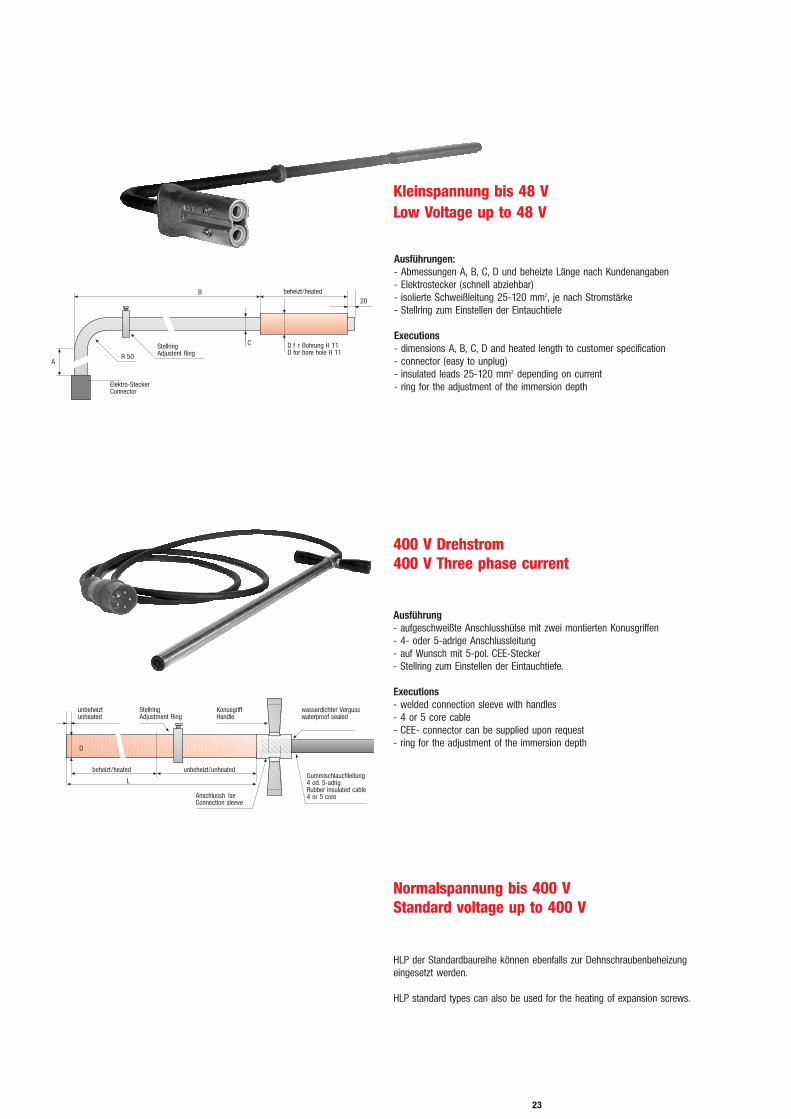
Kleinspannung bis 48 VLow Voltage up to 48 V
Normalspannung bis 400 VStandard voltage up to 400 V
400 V Drehstrom400 V Three phase current
Ausführung- aufgeschweißte Anschlusshülse mit zwei montierten Konusgriffen- 4- oder 5-adrige Anschlussleitung - auf Wunsch mit 5-pol. CEE-Stecker- Stellring zum Einstellen der Eintauchtiefe.
Executions- welded connection sleeve with handles- 4 or 5 core cable - CEE- connector can be supplied upon request- ring for the adjustment of the immersion depth
Ausführungen:- Abmessungen A, B, C, D und beheizte Länge nach Kundenangaben- Elektrostecker (schnell abziehbar)- isolierte Schweißleitung 25-120 mm2, je nach Stromstärke - Stellring zum Einstellen der Eintauchtiefe
Executions- dimensions A, B, C, D and heated length to customer specification- connector (easy to unplug)- insulated leads 25-120 mm2 depending on current- ring for the adjustment of the immersion depth
HLP der Standardbaureihe können ebenfalls zur Dehnschrauben beheizungeingesetzt werden.
HLP standard types can also be used for the heating of expansion screws.
24
ÜBERSICHT ANSCHLUSSARTENOVERVIEW CONNECTION TYPES
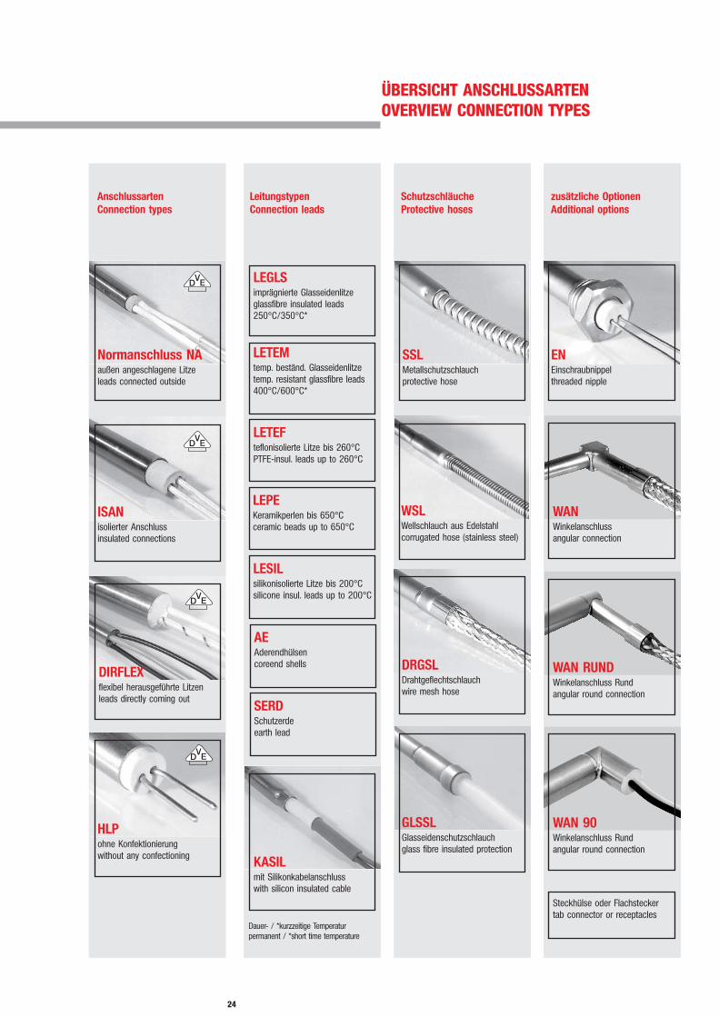
AnschlussartenConnection types
LeitungstypenConnection leads
LETEMtemp. beständ. Glas sei den lit ze temp. resistant glassfibre leads 400°C/600°C*
SchutzschläucheProtective hoses
DRGSLDrahtgeflechtschlauchwire mesh hose
zusätzliche OptionenAdditional options
Normanschluss NAaußen angeschlagene Litzeleads connected outside
ISANisolierter Anschlussinsulated connections
DIRFLEXflexibel herausgeführte Litzenleads directly coming out
LEGLSimprägnierte Glasseidenlitzeglassfibre insulated leads250°C/350°C*
LESILsilikonisolierte Litze bis 200°Csilicone insul. leads up to 200°C
LEPEKeramikperlen bis 650°C ceramic beads up to 650°C
LETEFteflonisolierte Litze bis 260°CPTFE-insul. leads up to 260°C
KASILmit Silikonkabelanschlusswith silicon insulated cable
GLSSLGlasseidenschutzschlauchglass fibre insulated protection
SSLMetallschutzschlauchprotective hose
WSLWellschlauch aus Edelstahlcorrugated hose (stainless steel)
ENEinschraubnippel threaded nipple
Steckhülse oder Flachsteckertab connector or receptacles
AEAderendhülsencoreend shells
SERDSchutzerdeearth lead
HLPohne Konfektionierungwithout any confectioning
Dauer- / *kurzzeitige Temperaturpermanent / *short time temperature
WANWinkelanschlussangular connection
WAN RUNDWinkelanschluss Rundangular round connection
WAN 90Winkelanschluss Rundangular round connection

25
ANSCHLUSSARTENCONNECTION TYPES
Anschlussleitungen und TemperaturbelastbarkeitLEGLS imprägnierte Glasseidenlitze bis ca. 250°C DauertemperaturLETEM temperaturbeständige Glasseidenlitze
bis 400°C Dauertemperatur LEPE Keramikperlen bis 650°C nur für Heizpatronen ab Ø 10 mmLETEF teflonisolierte Litze bis 260°CLESIL silikonisolierte Litze bis 200°CSERD Schutzerde
Connection leads in accordance with temperature loadsLEGLS Impregnated glassfibre insulated leads up to max. 250°C
permanent temperatureLETEM Temperature resistant glassfibre insulated leads
up to 400°C permanentlyLEPE Ceramic beads up to 650°C, only for HLP from Ø 10 mmLETEF PTFE-insulated leads up to about 260°C LESIL Silicon insulated leads up to 200°C SERD Earth leads
Ø (mm) Länge LEGLS LETEF LESIL LETEM SERD Length ISAN NA ISAN NA ISAN NA ISAN NA
6,5 250 210 500 210 001 210 520 211 000 210 780 - 210 880 210 800 210 160500 210 501 210 003 210 521 211 001 210 781 - 210 881 210 801 210 161800 210 633 210 004 210 535 211 002 210 782 - 210 882 210 802 210 162
1000 210 634 210 005 210 536 211 003 210 783 - 210 883 210 803 210 1631500 210 656 210 084 210 532 211 004 210 784 - 210 884 210 804 210 1642000 210 570 210 085 210 672 211 005 210 785 - 210 885 210 805 210 165
8/10 250 210 504 210 007 210 522 210 796 211 068 210 714 210 844 210 806 210 160500 210 505 210 009 210 523 210 797 211 083 210 715 210 845 210 807 210 161800 210 625 210 010 210 660 210 798 211 084 210 716 210 846 210 808 210 162
1000 210 626 210 011 210 538 210 799 211 085 210 717 210 847 210 809 210 1631500 210 640 210 086 210 534 210 792 210 938 210 718 210 848 210 810 210 1642000 210 679 210 087 210 651 210 794 211 086 210 719 210 849 210 811 210 165
12,5 250 210 506 210 013 210 524 211 091 210 540 210 720 210 850 210 812 210 172500 210 507 210 015 210 525 210 955 210 541 210 721 210 851 210 813 210 173800 210 619 210 016 210 737 210 970 210 703 210 722 210 852 210 814 210 174
1000 210 620 210 017 210 537 211 114 210 704 210 723 210 853 210 815 210 1751500 210 685 210 088 210 539 210 978 210 705 210 724 210 854 210 816 210 1762000 210 661 210 089 210 738 210 992 210 706 210 725 210 855 210 817 210 177
16 250 210 508 210 019 210 526 210 742 210 542 210 726 210 856 210 818 210 178500 210 509 210 021 210 527 211 012 210 543 210 352 210 857 210 819 210 179800 210 584 210 022 210 739 210 744 210 549 210 727 210 858 210 820 210 180
1000 210 618 210 023 210 740 210 743 210 707 210 728 210 859 210 821 210 1811500 210 689 210 090 210 675 210 745 210 708 210 729 210 860 210 822 210 1822000 210 684 210 091 210 676 210 746 210 709 210 730 210 861 210 823 210 183
20 250 210 510 210 025 210 528 210 103 210 544 210 731 210 862 210 824 210 184500 210 511 210 027 210 530 210 104 210 545 210 732 210 863 210 825 210 185800 210 616 210 028 210 974 210 105 210 710 210 733 210 864 210 826 210 186
1000 210 617 210 029 210 975 210 106 210 711 210 734 210 865 210 827 210 1871500 210 610 210 092 210 531 210 107 210 712 210 735 210 866 210 828 210 1882000 210 611 210 093 210 533 210 108 210 713 210 736 210 867 210 829 210 189
DE
HinweisDie verdichteten Heizelemente Typ HLP und PMV, können in verschiede-nen Anschlussvarianten bezogen werden: Eine Konfektionierung mit verschiedenen Anschlussleitungen ist möglich.Die aufgeführten Standardlängen sind ab Lager lieferbar. Die Querschnitterichten sich nach dem jeweiligen Patronendurchmesser.Leitungsenden sind abisoliert und werden auf Wunsch konfektioniert mitAderendhülsen (AE), Kabelschuhe (KS), Steckhülse oder Flachstecker.Weitere Varianten auf Anfrage.
Please noteThe heating elements type HLP and PMV can be equipped with differentconnection leads. The standard lengths listed in the table below are deli-verable from stock. Their cross sections refer to the respective cartridgediameter. Bare lead ends can be furnished with coreend shells, cablesockets M4, or tab connectors or receptacles and other accessories upon request.

26
ENEinschraubnippelThreaded nipple
Beschreibung: Die Heizelemente Typ HLP und PMV können zur Befestigung mitEinschraubnippeln aus Messing oder Edelstahl ausgerüstet werden. Die Edelstahlnippel werden auf die Patronen geschweißt, die Messing -nippel hartgelötet. Patronen mit nebenstehenden Nippelab mes sun gen sind kurzfristig lieferbar.
Description:The heating elements type HLP and PMV can be equipped with a threa-ded nipple made of brass or stainless steel. Brass nipples will be solderedto the cartridge, stainless steel nipples will be welded. Heaters with thenipple dimensions indicated beside can be delivered at short notice.
Ø A 6,5 8 10 12,5 16 20B 6 6 6,5 6,5 8,5 12C 3 4 4,5 4,5 5,5 6
Patronen-Ø Bezeichnung Messing EdelstahlCartridge-Ø Designation Brass nipple Stainless steel
6,5 mm M 10 x 1,0 SW 12 610 073 610 0848,0 mm M 12 x 1,0 SW 14 610 074 610 082
10,0 mm M 14 x 1,5 SW 17 610 075 610 08312,5 mm M 16 x 1,5 SW 19 610 076 610 07916,0 mm M 20 x 1,5 SW 24 610 077 610 08020,0 mm M 26 x 1,5 SW 30 610 078 610 081
ISANIsolierter AnschlussInsulated connection
Beschreibung:Litzen isoliert aus dem Keramikkopf herausgeführt.Das bestehende Lagerprogramm verdichteter Heizelemente kann auch inISAN-Ausführung geliefert werden. Dabei ist die Höhe des Keramikkopfes7-14 mm. Auf Wunsch kann diese Ausführung auch flüssigkeitsgeschütztgestaltet werden. Diese Ausführung hat das VDE-Zeichen.
Description:The available stock programme of compacted heating elements can alsobe equipped with flexible connection leads being insulated and led outdirectly from the cartridge. The protruding height of the ceramic discsfrom the sheath is 7-14 mm. Upon request this execution can also beprotected against ingress of liquids. This execution has a VDE sign.
Ø A 6,5 8 10 12,5 16 20B 7 7 9 11,5 12,5 14
Ø C 6 7,5 9 10,5 12,5 16
NANorm-Anschluss Standard connection
BeschreibungLitzenanschluss außerhalb der Patrone
DescriptionLeads connected outside of the heater
Ø A 6,5 8 10 12,5 16 20B 3 4 4 4,5 4,5 5C 45 45 45 45 45 45

27
SSLMetallschutzschlauch Typ SSL Protective hose type SSL
Beschreibung: Wendelgewickelter Metallschlauch aus verzinktem Stahl -band für Patronendurchmesser 6,5 bis 20 mm. Diese Ausführung ist nichtfür bewegte Teile zugelassen. Sie schützen die Anschluss leitungen vormechanischer Beschädigung. Das Rohrstück verbindet die Patrone mitdem Metallschlauch. Es ist über bzw. in die Heizpatrone geschoben undgeschweißt.Einsatz: mechan. bzw. Knickschutz
Description: Protective hose made of spirally shaped, wound, galvanisedsteel ribbon for cartridge heaters with diameters from 6.5 mm through Ø 20 mm. This hose protects the connections from mechanical damagebut cannot be used when the heaters are subject to a lot of movement. Aconnection tube joins the cartridge heater to the protective hose. Thehose is mounted into the tube or around its outer diameter and welded.Usage: Protecion against mechanical damage, strain relief
Ø A 6,5 8 10 12,5 16 20B 32 38 38 38 38 38
Ø C 7,5 9 11,5 14 18 22Ø D 6 8 10 10 14 14
E Länge Schutzschlauch gemäß AngebotLength of the protective hose according to offer
F Länge Litze gemäß AngebotLength of the lead according to offer
KASILsilikonisoliertes KabelSilicon insulated cable
Beschreibung: Silikonkabel als Anschlussausführung mit wasserdichtemSilikon- oder Epoxidharzverguss. Alle HLP-Durchmesser können wahlweisemit 2-adrigen und 3-adrigen Silikonleitungen konfektioniert werden.Einsatz: Nass- und Feucht bereiche
Description: Cartridge heaters with silicon insulated cables type KASILas a connection cable with waterproof connection. All HLP-diameters can optional be equipped with a two core or a three core silicon insulated cable. Usage: wet rooms or under humidity
Ø A 6,5 8 10 12,5 16 20B 32 38 38 38 38 38
Ø C 7,5 9 11,5 14 18 22Ø D 7 8 8 8 9 9
SCHUTZSCHLÄUCHEPROTECTIVE HOSES
BEWI BefestigungswinkelFastening Bracket
Ø A 6,5 8 10 12,5 16 20B 8,25 9 10 11,25 13 15

28
SSL, WSL, DRGSL, GLSSLSchutzschlauch innenliegendProtective hose inside the cartridge
Beschreibung: möglich bei SSL, WSL, DRGSL, GLSSL, ab ≥ Ø 10 mm. Einsatz: empfohlen bei Anwendungen, bei denen die Anschlüsse durch die
Bohrung geführt werden müssen
Description: possible for SSL, WSL, DRGSL, GLSSL for heaters with diameter ≥ Ø 10 mm
Usage: recommended for applications where the connection must be passedtotally through a bore hole
WSLWellschlauch Corrugated hose
Beschreibung: Wellschlauch aus Edelstahl für Patronendurchmesser 6,5bis 20 mm. Der Wellschlauch ist mit einem Rohrstück dicht hartgelötetund das Rohrstück auf die Heizpatrone dicht geschweißt oder hartgelötet.Einsatz: mechan. Schutz bzw. Knickschutz, wasserdicht
Description: Corrugated hose made of stainless steel for cartridge heatersfrom Ø 6.5 mm through Ø 20 mm. The corrugated hose is soldered tightinto a connection tube which again is soldered or welded tight onto theconnection end.Usage: Protection against mechanical damage, waterproof
DRGSLDrahtgeflechtschlauch Wire mesh hose
Beschreibung: Drahtgeflechtschlauch aus verzinktem Drahtgeflecht fürPatronendurchmesser 6,5 mm bis 20 mm. Rohranschluss außenliegend.Einsatz: für bewegte Teile
Description: Wire mesh hose made of galvanised wire netting for cartrid-ge heaters with diameters from 6.5 mm through 20 mm. The connectiontube for the wire mesh hose protrudes over the cartridge diameter.Usage: recommended for moving parts
Ø A 6,5 8 10 12,5 16 20B 32 38 38 38 38 38
Ø C 7,5 9 11,5 14 18 22Ø D 9 9 10 10 12,5 12,5
E Länge Schutzschlauch gemäß AngebotLength of the protective hose according to offer
F Länge Litze gemäß AngebotLength of the lead according to offer
Ø A 6,5 8 10 12,5 16 20B 32 38 38 38 38 38
Ø C 7,5 9 11,5 14 18 22Ø D 6,2 6,2 10,2 10,2 10,2 10,2
E Länge Schutzschlauch gemäß AngebotLength of the protective hose according to offer
F Länge Litze gemäß AngebotLength of the lead according to offer
Ø A 10 12,5 16 20B 35 35 35 35
Ø C 8,5 11 14 18Ø D SSL 8 10 10 14Ø D WSL 9 10 10 12,5Ø D DRGSL 6,2 10,2 10,2 10,2
E Länge Schutzschlauch gemäß AngebotLength of the protective hose according to offer
F Länge Litze gemäß AngebotLength of the lead according to offer

WANWinkel-Anschluss Typ WAN mit oder ohne SchutzschlauchAngular connection type WAN with or without metallic protective hose
1. Schutzschlauch WAN SSL2. Wellschlauch WAN WSL3. Drahtgeflechtschlauch WAN DRGSL4. silikonisoliertes Kabel WAN KASIL5. nur Winkelanschluss WAN
1. Protective hose WAN SSL2. Corrugated hose WAN WSL3. Wire mesh hose WAN DRGSL4. Silicon insulated cable WAN KASIL5. Angular connection WAN
Ø A 4 6,5 8 10 12,5 16 20B 32 32 38 38 38 38 38
Ø C 5 7,5 9 11,5 14 18 22Ø D siehe S. 27/28 see page 27/28
E 5 8 10 12 14 18 22F Länge Schutzschlauch gemäß Angebot
Length of the protective hose according to offerG Länge Litze gemäß Angebot
Length of the lead according to offer
29
WAN Rund/RoundRunder Winkel-Anschluss Typ WAN-Rund mit oder ohne SchutzschlauchRound angular connection type WAN-Round with or without metallic protective hose
Beschreibung: siehe Typ WANDescription: see type WAN
WINKEL-ANSCHLUSSARTENANGULAR CONNECTIONS
Ø A 6,5 8 10 12,5 16 20Ø B 6 7,5 9,5 12 15 19Ø C 5 6,5 9,0 11,5 14 18
D 7,75 9,0 11,5 14,0 16,5 20,5E Länge Schutzschlauch gemäß Angebot
Length of the protective hose according to offerF Länge Litze gemäß Angebot
Length of the lead according to offer
WAN 90Runder Winkel-Anschluss Typ WAN 90 mit oder ohne SchutzschlauchRound angular connection type WAN 90 with or without metallic protective hose
Beschreibung: siehe Typ WANDescription: see type WAN
Ø HLP Ø D1/D2 L1 L220 mm 19,5 22 403/4” 18,5 22 4016 mm und 5/8” 15,5 18 3512,5 mm und 1/2” 12 14,5 30
10 mm 9,5 12 25
3/8” 9 12 25
8 mm und 5/16” 7,5 10 20
6,5 mm und 1/4” 6 7,5 12,5

30
WEITERE ANSCHLUSSARTENFURTHER CONNECTION TYPES
GLEITMITTELINSTALLATION AID
Auf Anfrage erhalten sie bei uns selbstverständlich weitereAnschlussformen.
If requested we can supply furtherspecial connection types too.
Bestellung Ordering Varybond Regular Grade, 100 g, ab Lager Varybond Regular Grade, 100 g, ex-stock Artikel-Nr. 650 206
D
E
Zum Einbau verdichteter Heizelemente in Bohrungen mit Feintoleranz emp-fehlen wir die Verwendung des hochtemperaturbeständigen GleitmittelsVARYBOND REGULAR GRADE. Es ist ungiftig und neutral. Es kann imTemperatur bereich von -188°C bis + 958°C eingesetzt werden.
Vor der Montage wird das Gleitmittel auf das Heizelement oder in derBohrung aufgetragen. Es reduziert die Reibung und erleichtert somit denEinbau. Anderseits verhindert es das Festfressen der Patronen und derAusbau wird vereinfacht.
For the insertion of compacted cartridge heaters into drilled holes with atight tolerance we recommend the use of the high temperature constantlubricant VARYBOND REGULAR GRADE. It is not poisonous and neutral. Itcan be used in a temperature range from -188°C to + 958°C.
The lubricant should be applied over the sheath of the cartridge heater orin the drilled hole before inserting the heating element. It reduces frictionand thus facilitates insertion. Furthermore it prevents the seizing of thecartridge heater and simplifies their removal.
31
EINBAUHINWEISEINSTALLATION GUIDANCE
D
E
13 Punkte für den erleichterten Umgang mit verdichteten Heizpatronen
● Für Heizpatronen mit Oberflächenbelastungen bis zu 20 W/cm2 ist die Auf -nah me bohrung nach ISO H7 mit möglichst geringer Rauhtiefe auszuführen.
● Für Heizpatronen mit Oberflächenbelastungen über 20 W/cm2 ist einPress sitz erforderlich, der durch individuelle Einpassung der Patronenerreicht werden kann.
● Die Aufnahmebohrungen für Heizpatronen müssen zylindrisch sein.Kreu zende Bohrungen und Lunker verursachen einen Wärmestau undverkürzen die Lebens dauer der Heizelemente.
● Die Aufnahmebohrungen sollten zur Erleichterung des Ein- und Ausbausder Heizelemente durchgehend ausgeführt werden (evtl. abgesetzteBohrungen).
● Die angegebene Betriebstemperatur der Heizpatronen gilt nicht fürAnschluss leitungen. Diese müssen für den jeweiligen Anwendungsfallpassend gewählt werden.
● Das temperaturbeständige Gleitmittel VARYBOND REGULAR GRADEerleichtert bei kleinem Bohrungsspiel den Ein- und Ausbau derHeizelemente und ist gleichzeitig ein Korrosionsschutz.
● Beim Einsatz mehrerer Heizpatronen sollte der Abstand zwischen zweiPa tronen mindestens so groß sein wie der Patronendurchmesser.
● Der Bereich des Anschlusskopfes sollte vor flüssigen und pasteusenMedien sowie deren Dämpfen (Gleitmittel, Öl, Kunststoffe usw.)geschützt werden, da sonst an der Austrittsstelle der ZuleitungKriechströme bzw. Überschläge auftreten.
● Die Zuleitungen sollten im Bereich des Austritts aus der Heizpatronegegen mechanische Schwingungen geschützt sein. Eventuell entstehen-de Dämpfe bei der Erhitzung der Isolation müssen frei abziehen können.
● Die Überwachung der Arbeitstemperatur sollte nach Möglichkeit mit stetigen Reglern, Reglern mit Impulsbreitenmodulation oder elektroni-schen Leistungs steuergeräten vorgenommen werden. Häufig führt einezu träge Regelstrecke zu thermischer Überlastung der Heizelemente.Deshalb ist der Tempe ratur fühler in unmittelbarer Nähe (ca. 10 mmAbstand) der Heiz patro nen anzubringen.
● Die Lagerung von Heizelementen über längere Zeiträume muss in abso-lut trockenen Räumen oder in luftdicht verschlossenen Plastikbeutelnerfolgen. Wenn Heizpatronen Feuchtigkeit gezogen haben, können sie ineinem Trockenofen bei 180°C während 8 Stunden getrocknet werden.
● Die Erdung der Heizelemente muss durch einen entsprechenden Einbaugewährleistet werden, sofern die Heizelemente nicht mit Erdanschlussbestellt werden.
● Achtung: Gegebenenfalls können bei Heizpatronen Silikonaus -scheidungen austreten. Fragen Sie uns, wenn Sie silikonfreieHeizpatronen wünschen.
13 points to be observed when using highly compacted heating elements
● For cartridge heaters with surface loads up to 20 W/cm2 the receivinghole must be drilled according to ISA H7 with peak to valley height assmall as possible.
● For cartridge heaters with surface loads exceeding 20 W/cm2 a press fit isnecessary which can be obtained by individual attention beeing paid toeach cartridge heater.
● The drilled receiving bores of cartridge heaters must be cylindrical.Crossing bores and shrinkages cause a localisation of heat and shortenthe useful life of the heating elements.
● To facilitate the insertion and the removal of the heating elements thereceiving bores should be drilled in a continuous motion (to avoid a stepped bore).
● The maximum working temperature of the cartridge heaters stated in theleaflet does not apply to the connection leads. These must be selectedaccording to the operating conditions.
● The lubricant VARYBOND REGULAR GRADE beeing resistant to temperaturefacilitates the in sertion and removal of the heating elements in bores withsmall tolerances.
● When using several cartridge heaters the distance between two con -secutive cartridges should be at least equal to the cartridge diameter.
● The end of the cartridge heater with the connection leads should be pro-tected against liquid and pasty media (lubricants, oil, synthetic materials,etc.) as well as their vapours because otherwise leakage currents and,possibly flashover could occur at the outlet connection terminals.
● The connection leads should be protected against mechanical vibrationsclose to the outlet of the cartridge heater. If they are heated with the cartridge, the resulting vapour must have the ability to escape.
● If possible, control of the operating temperature should be achieved bymeans of continuous regulators, controllers with pulse width modulation orelectronic power control devices. A control system with long timelag oftencauses thermal overload of the heating elements. For this reason also the temperature sensor must be fitted in close proximity to the cartridgeheater (about 10 mm apart).
● If heating elements are to be stored for long periods they should be housed in absolutely dry rooms or enclosed in plastic bags which are hermetically sealed. If cartridge heaters are moist, they can be dried byheating at 180°C for 8 hours.
● If the heaters are not supplied with a separate earth lead the installationhas to provide a safe ground connection.
● Caution: In some cases silicone can run out of cartridge heaters. Please ask us if you wish cartridge heaters free of silicone.

Wärmstens möchten wir Ihnen unsere neuesten, aber auch unsere etablierten Entwicklungen auf dem Gebiet der elektrischen Behei zungs -technik empfehlen.
We highly recommend to you our established wide range of products aswell as our latest developments in the field of electric heating elements.
Einschraubheizkörper Typ EHKImmersion heaters type EHK
Hochleistungs-Rohrpatronen Typ RPTubular cartridge heater type RP
Lufterhitzer Typ HRR/RHR/PKAir heater type HRR/RHR/PK
Rohrheizkörper Typ RHKTubular heaters type RHK
Thermoelemente Typ TETemperature sensors type TE
Flexibler Rohrheizkörper Typ FLEXFlexible tubular heater type FLEX
IHR KOMPETENTER PARTNERYOUR COMPETENT PARTNER
HINWEISEADVICE
GewährleistungsausschlussEine Gewährleistung für Schäden durch fehlerhaften Einbau und auch beiErteilung von Ratschlägen wird nicht übernommen.
WarrantyWe cannot take responsibility for any defect caused by improper installati-on or any advice given for the use of our heaters.
AusbauhinweisBeim Ausbau der Heizpatrone ist darauf zu achten, dass die Bohrung nichtbeschädigt wird. Bei durchgehenden Bohrungen ist ein rohrförmigerDurchschlag zu verwenden, der in die im Patronenboden befindlicheRingnut passt. So wird ein Aufstauchen des Patronen bodens weitgehendverhindert. Durch Ziehen an den Anschlussleitungen bzw. am Keramikkopfder Heizpatronen ist ein Ausbau meist nicht möglich.
Removal of heatersWhen removing catridge heaters, please take care not to damage the borehole. If there is a through hole use a punch in tube form that fits into thering groove at the bottom end of the cartridge. In this way you can avoidpuncturing the cartridge bottom. Removal of the cartridge heater by pullingthem off the bore hole by the connection leads or the ceramic head isnot possible in most cases.
Türk+Hillinger GmbHFöhrenstr. 20 D-78532 TuttlingenTel. 0 74 61-70 140 Fax 70 14110
Türk+Hillinger Elektrowärme GmbHDorotheenstr. 22 D-09212 Limbach-OberfrohnaTel. 0 37 22-7189 0 Fax 718916
02.2
018.
1000
T
ECHN
ISCH
E ÄN
DERU
NGEN
VOR
BEHA
LTEN
/TEC
HNIC
AL D
ATA
ARE
SUBJ
ECT
TO C
HANG
E
Turk+Hillinger USA, Inc.6650 W. Snowville Road, Suite WP.O. Box 41371 Brecksville, Ohio 44141, USA
Tel. +1 440-512 71 44Fax +1 440-512 71 [email protected]