HIGH-PERFORMANCE ANCHOR WITH … · M8-M20 Anchor Design Software INSTALLATION ... spacing s ≥ 15...
6
182 Heavy duty fixings F120 M8-M20 Anchor Design Software INSTALLATION SCHEME T inst 3 4 1 2 VOORDELEN • Veiligheidsanker ETA optie 1 met 3 expansiezones voor beperkte rand en h.o.h.-afstanden. • Hoge uittrekwaarden en afschuiflasten. • Verschillende uitvoeringen voor een mooie afwerking. AVANTAGES • Ancrage de sécurité ATE option 1 avec 3 zones d’expansion qui permettent des distances aux bords et entraxes minimaux. • Efforts de traction et de cisaillement plus élevés. • Différentes types pour un montage visuellement agréable. TOEPASSING • Doorsteekmontage. • Als het anker wordt aangedraaid, wordt de conus in de ankerhuls getrokken en zich zo tegen de boorgatwand klemt. APPLICATION • Installation traversante. • Lorsque l’ancrage est serré, le cône est tiré dans la bague qui s’expanse contre les parois du béton. HIGH-PERFORMANCE ANCHOR WITH COUNTERSUNK HEAD SCREW SMZAV ADVANTAGES • Safety anchor ETA option 1 with a three part expansion sleeve. This allows smaller spacings and edge distances. • The plastic compression ring ensures the clamping of the mounted piece to the work surface. • Three different models of the highload anchor are available. FUNCTIONING • Push-through installation. • When installing the anchor, the cone is pulled in the sleeve. Afterwards the anchor can be dismantled with a flush result. Cr3+ environmental friendly TYPE SZ-SK Torque controlled expansion anchor for use in concrete under static or quasi-static action and fire exposure. ZWAARLASTANKER MET VERZONKEN KOP Moment-gecontroleerd doorsteekanker met Europese technische keuring voor gescheurd beton en brandweerstandskeuring. ANCRAGE HAUTE-PERFORMANCE AVEC VIS TÊTE FRAISÉE Goujon d’ancrage à expansion contrôlée avec approbation technique européenne pour béton fissuré et résistance au feu. M12
Transcript of HIGH-PERFORMANCE ANCHOR WITH … · M8-M20 Anchor Design Software INSTALLATION ... spacing s ≥ 15...

182
Hea
vy d
uty
fixings
F120
M8-M20Anchor Design
Software
INSTALLATION SCHEME Tinst3 41 2
VOORDELEN• Veiligheidsanker ETA optie 1 met 3 expansiezones voor beperkte rand en
h.o.h.-afstanden.• Hoge uittrekwaarden en afschuiflasten.• Verschillende uitvoeringen voor een mooie afwerking.
AVANTAGES• Ancrage de sécurité ATE option 1 avec 3 zones d’expansion qui permettent
des distances aux bords et entraxes minimaux.• Efforts de traction et de cisaillement plus élevés.• Différentes types pour un montage visuellement agréable.
TOEPASSING• Doorsteekmontage.• Als het anker wordt aangedraaid, wordt de conus in de ankerhuls getrokken
en zich zo tegen de boorgatwand klemt.
APPLICATION• Installation traversante.• Lorsque l’ancrage est serré, le cône est tiré dans la bague qui s’expanse
contre les parois du béton.
HIGH-PERFORMANCE ANCHOR WITH COUNTERSUNK HEAD SCREW
SMZAV
ADVANTAGES• Safety anchor ETA option 1 with a three part expansion sleeve. This allows
smaller spacings and edge distances.• The plastic compression ring ensures the clamping of the mounted piece to
the work surface.• Three different models of the highload anchor are available.
FUNCTIONING• Push-through installation.• When installing the anchor, the cone is pulled in the sleeve. Afterwards the
anchor can be dismantled with a flush result.
Cr3+environmentalfriendly
TYPE SZ-SK
Torque controlled expansion anchor for use in concrete under static or quasi-static action and fire exposure.
ZWAARLASTANKER MET VERZONKEN KOPMoment-gecontroleerd doorsteekanker met Europese technische keuring voor gescheurd beton en brandweerstandskeuring.
ANCRAGE HAUTE-PERFORMANCE AVEC VIS TÊTE FRAISÉEGoujon d’ancrage à expansion contrôlée avec approbation technique européenne pour béton fissuré et résistance au feu.
M12
183
Hea
vy d
uty
fixings
ls tfix
d1hef
h1hmin
hnom
d0 ds
SW
Tinst
d2
h
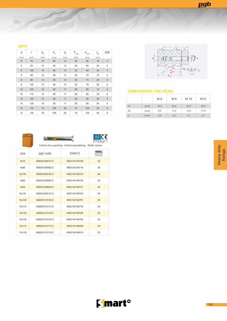
size pgb code EAN13
6x70 SMZAV306070 Z 5902134190709 50
6x85 SMZAV306085 Z 5902134190716 50
6x100 SMZAV306100 Z 5902134190723 50
8x80 SMZAV308080 Z 5902134190730 50
8x95 SMZAV308095 Z 5902134190747 50
8x120 SMZAV308120 Z 5902134190754 25
10x100 SMZAV310100 Z 5902134190761 25
10x110 SMZAV310110 Z 5902134190778 25
10x120 SMZAV310120 Z 5902134190785 25
10x135 SMZAV310135 Z 5902134190792 25
12x115 SMZAV312115 Z 5902134190808 20
12x135 SMZAV312135 Z 5902134190815 20
Carton box packing - Kartonverpakking - Boîte carton
INFOd
[mm]
l[mm]
d0
[mm]
h1
[mm]
df
[mm]
Tinst
[Nm]
hnom
[mm]
tfix
[mm]
SW
6 70 10 65 12 20 60 10 4
6 85 10 65 12 20 60 25 4
6 100 10 65 12 20 60 40 4
8 80 12 80 14 25 70 10 5
8 95 12 80 14 25 70 25 5
8 120 12 80 14 25 70 50 5
10 100 15 95 17 55 85 10 6
10 110 15 95 17 55 85 25 6
10 120 15 95 17 55 85 35 6
10 135 15 95 17 55 85 50 6
12 115 18 105 20 70 105 20 8
12 135 18 105 20 70 105 40 8
DIMENSIONS CSK HEAD
M 6 M 8 M 10 M12
d1 [mm] 16,5 20,5 24,5 29,5
d2 [mm] 9,5 11,5 14,5 17,5
h [mm] 3,9 5,0 5,7 6,7

184
Hea
vy d
uty
fixings
TENSION RESISTANCE CAPACITY UNDER FIRE EXPOSURE FOR CONCRETE C20/25-C50/60
TREKBELASTING [KN] BIJ BLOOTSTELLING AAN VUUR VOOR GESCHEURD EN NIET-GESCHEURD BETON C20/25-C50/60RÉSISTANCE DE TRACTION ([KN] PAR EXPOSITION AU FEU POUR DU BÉTON FISSURÉ ET NON FISSURÉ C20/25-C50/60
M 6 M 8 M 10 M12
F 30 [min] 1,00 1,90 4,00 6,30
F 60 [min] 0,80 1,50 3,20 4,60
F 90 [min] 0,60 1,00 2,10 3,00
F 120 [min] 0,40 0,80 1,50 2,00
1) Load figures are based on ETA 17-0784 and include the resistances’ partial safety factors as per approvals and a partial safety factor on the action of γF= 1.4. Load figures apply for a rebar spacing s ≥ 15 cm or alternatively for a rebar spacing s ≥ 10 cm in combination with a rebar diameter of ds ≤ 10 mm. 3) Shear load figures are valid for cracked and non-cracked concrete C20/25-C50/60 and apply for an anchor without influence of a concrete edge. For shear loads close to an edge (c ≤ 10 x hef), concrete edge failure has to be checked as per ETAG, Annex C, Design Method A.
LOADS - BELASTINGEN - CHARGES
Recommended loads for a single anchor. 1)
Maximaal aanbevolen belasting voor één anker.Charges maximales recomandées pour un ancrage simple.
Type SZ-S M 6 M 8 M 10 M12
Embedment depth / Verankeringsdiepte / Profondeur d’ancrage hef [mm] 50 60 71 80
Min. spacing / Min h.o.h.-afstand / Distance entre-axes min. smin [mm] 50/80 60/100 70/120 80/160
Critical spacing / Kritieke h.o.h.-afstand / Distance entre-axes critique scr,N [mm] 150 180 213 240
Min. thickness of concrete member / Min. betondikte / Epaisseur min. du béton hmin [mm] 100 120 140 160
Min. edge distance / Min. randafstand / Distance au bord min. Cmin [mm] 50/100 60/120 70/175 80/200
Critical edge distance / Kritieke randafstand / Distance au bord critique Ccr,N [mm] 75 90 106,5 120
Tension load / Trekbelasting / Traction
Uncracked concrete / Niet-gescheurd beton / Béton non fissuré
Concrete / Beton / Béton C20/25 [kN] 7,6 9,5 14,3 17,2
Concrete / Beton / Béton C25/30 [kN] 7,6 10,5 15,7 18,9
Concrete / Beton / Béton C30/37 [kN] 7,6 11,6 17,4 21
Concrete / Beton / Béton C40/50 [kN] 7,6 13,4 20,1 24,2
Concrete / Beton / Béton C50/60 [kN] 7,6 13,8 21,9 26,6
Cracked concrete / Gescheurd beton / Béton fissuré
Concrete / Beton / Béton C20/25 [kN] 2,4 5,7 7,6 12,3
Concrete / Beton / Béton C25/30 [kN] 2,6 6,3 8,4 13,5
Concrete / Beton / Béton C30/37 [kN] 2,9 7 9,3 15
Concrete / Beton / Béton C40/50 [kN] 3,4 8,1 10,7 17,3
Concrete / Beton / Béton C50/60 [kN] 3,7 8,9 11,8 19
Shear load / Afschuifbelasting / Cisaillement 2)
Concrete / Beton / Béton C20/25 [kN] 10,3 15,9 / 17,1 20,5 / 274 24,5/ 34,3
Concrete / Beton / Béton > C20/25 [kN] 10,3 17,1 22,6 / 27,4 27,0 / 37,8
Bending moments / Buigmoment / Moment de flexion [Nm] 6,9 17,1 34,3 60,0
F120

185
Hea
vy d
uty
fixings
F120
M8-M20Anchor Design
Software
INSTALLATION SCHEME Tinst3 41 2
VOORDELEN• Veiligheidsanker ETA optie 1 met 3 expansiezones voor beperkte rand en
h.o.h.-afstanden.• Hoge uittrekwaarden en afschuiflasten.• Verschillende uitvoeringen voor een mooie afwerking.
AVANTAGES• Ancrage de sécurité ATE option 1 avec 3 zones d’expansion qui permettent
des distances aux bords et entraxes minimaux.• Efforts de traction et de cisaillement plus élevés.• Différentes types pour un montage visuellement agréable.
TOEPASSING• Doorsteekmontage.• Als het anker wordt aangedraaid, wordt de conus in de ankerhuls getrokken
en zich zo tegen de boorgatwand klemt.
APPLICATION• Installation traversante.• Lorsque l’ancrage est serré, le cône est tiré dans la bague qui s’expanse
contre les parois du béton.
HIGH-PERFORMANCE ANCHOR WITH COUNTERSUNK HEAD SCREW
SMZAV
ADVANTAGES• Safety anchor ETA option 1 with a three part expansion sleeve. This allows
smaller spacings and edge distances.• The plastic compression ring ensures the clamping of the mounted piece to
the work surface.• Three different models of the highload anchor are available.
FUNCTIONING• Push-through installation.• When installing the anchor, the cone is pulled in the sleeve. Afterwards the
anchor can be dismantled with a flush result.
Cr3+environmentalfriendly
TYPE SZ-SK
Torque controlled expansion anchor for use in concrete under static or quasi-static action and fire exposure.
ZWAARLASTANKER MET VERZONKEN KOPMoment-gecontroleerd doorsteekanker met Europese technische keuring voor gescheurd beton en brandweerstandskeuring.
ANCRAGE HAUTE-PERFORMANCE AVEC VIS TÊTE FRAISÉEGoujon d’ancrage à expansion contrôlée avec approbation technique européenne pour béton fissuré et résistance au feu.
M12

186
Hea
vy d
uty
fixings
ls tfix
d1hef
h1hmin
hnom
d0 ds
SW
Tinst
d2
h
size pgb code EAN13
8x80 SMZAV308080 A4 5902134190822 50
8x95 SMZAV308095 A4 5902134190839 50
8x120 SMZAV308120 A4 5902134190846 25
10x100 SMZAV310100 A4 5902134190853 25
10x110 SMZAV310110 A4 5902134190860 25
10x120 SMZAV310120 A4 5902134190877 25
10x135 SMZAV310135 A4 5902134190884 25
12x115 SMZAV312115 A4 5902134190891 20
12x135 SMZAV312135 A4 5902134190907 20
Carton box packing - Kartonverpakking - Boîte carton
INFOd
[mm]
l[mm]
d0
[mm]
h1
[mm]
df
[mm]
Tinst
[Nm]
hnom
[mm]
tfix
[mm]
SW
8 80 12 80 14 17,5 70 10 5
8 95 12 80 14 17,5 70 25 5
8 120 12 80 14 17,5 70 50 5
10 100 15 95 17 42,5 85 15 6
10 110 15 95 17 42,5 85 25 6
10 120 15 95 17 42,5 85 35 6
10 135 15 95 17 50 85 50 6
12 115 18 105 20 50 95 20 8
12 135 18 105 20 50 95 40 8
DIMENSIONS CSK HEAD
M 6 M 8 M 10 M12
d1 [mm] 16,5 20,5 24,5 29,5
d2 [mm] 9,5 11,5 14,5 17,5
h [mm] 3,9 5,0 5,7 6,7

187
Hea
vy d
uty
fixings
TENSION RESISTANCE CAPACITY UNDER FIRE EXPOSURE FOR CONCRETE C20/25-C50/60
TREKBELASTING [KN] BIJ BLOOTSTELLING AAN VUUR VOOR GESCHEURD EN NIET-GESCHEURD BETON C20/25-C50/60RÉSISTANCE DE TRACTION ([KN] PAR EXPOSITION AU FEU POUR DU BÉTON FISSURÉ ET NON FISSURÉ C20/25-C50/60
M 6 M 8 M 10 M12
F 30 [min] 1,00 1,90 4,00 6,30
F 60 [min] 0,80 1,50 3,20 4,60
F 90 [min] 0,60 1,00 2,10 3,00
F 120 [min] 0,40 0,80 1,50 2,00
1) Load figures are based on ETA 17-0784 and include the resistances’ partial safety factors as per approvals and a partial safety factor on the action of γF= 1.4. Load figures apply for a rebar spacing s ≥ 15 cm or alternatively for a rebar spacing s ≥ 10 cm in combination with a rebar diameter of ds ≤ 10 mm. 3) Shear load figures are valid for cracked and non-cracked concrete C20/25-C50/60 and apply for an anchor without influence of a concrete edge. For shear loads close to an edge (c ≤ 10 x hef), concrete edge failure has to be checked as per ETAG, Annex C, Design Method A.
LOADS - BELASTINGEN - CHARGES
Recommended loads for a single anchor. 1)
Maximaal aanbevolen belasting voor één anker.Charges maximales recomandées pour un ancrage simple.
Type SZ-S M 6 M 8 M 10 M12
Embedment depth / Verankeringsdiepte / Profondeur d’ancrage hef [mm] 50 60 71 80
Min. spacing / Min h.o.h.-afstand / Distance entre-axes min. smin [mm] 50/80 60/100 70/120 80/160
Critical spacing / Kritieke h.o.h.-afstand / Distance entre-axes critique scr,N [mm] 150 180 213 240
Min. thickness of concrete member / Min. betondikte / Epaisseur min. du béton hmin [mm] 100 120 140 160
Min. edge distance / Min. randafstand / Distance au bord min. Cmin [mm] 50/100 60/120 70/175 80/200
Critical edge distance / Kritieke randafstand / Distance au bord critique Ccr,N [mm] 75 90 106,5 120
Tension load / Trekbelasting / Traction
Uncracked concrete / Niet-gescheurd beton / Béton non fissuré
Concrete / Beton / Béton C20/25 [kN] 7,6 9,5 14,3 17,2
Concrete / Beton / Béton C25/30 [kN] 7,6 10,5 15,7 18,9
Concrete / Beton / Béton C30/37 [kN] 7,6 11,6 17,4 21
Concrete / Beton / Béton C40/50 [kN] 7,6 13,4 20,1 24,2
Concrete / Beton / Béton C50/60 [kN] 7,6 13,8 21,9 26,6
Cracked concrete / Gescheurd beton / Béton fissuré
Concrete / Beton / Béton C20/25 [kN] 2,4 5,7 7,6 12,3
Concrete / Beton / Béton C25/30 [kN] 2,6 6,3 8,4 13,5
Concrete / Beton / Béton C30/37 [kN] 2,9 7 9,3 15
Concrete / Beton / Béton C40/50 [kN] 3,4 8,1 10,7 17,3
Concrete / Beton / Béton C50/60 [kN] 3,7 8,9 11,8 19
Shear load / Afschuifbelasting / Cisaillement 2)
Concrete / Beton / Béton C20/25 [kN] 10,3 15,9 / 17,1 20,5 / 274 24,5/ 34,3
Concrete / Beton / Béton > C20/25 [kN] 10,3 17,1 22,6 / 27,4 27,0 / 37,8
Bending moments / Buigmoment / Moment de flexion [Nm] 6,9 17,1 34,3 60,0
F120