High Availability, Durability, and Disaster Recovery for ...
Junos Space Network ManagementPlatform
High Availability and Disaster Recovery Guide
Release
15.1
Modified: 2016-09-08
Copyright © 2016, Juniper Networks, Inc.

Juniper Networks, Inc.1133 Innovation WaySunnyvale, California 94089USA408-745-2000www.juniper.net
Copyright © 2016, Juniper Networks, Inc. All rights reserved.
Juniper Networks, Junos, Steel-Belted Radius, NetScreen, and ScreenOS are registered trademarks of Juniper Networks, Inc. in the UnitedStates and other countries. The Juniper Networks Logo, the Junos logo, and JunosE are trademarks of Juniper Networks, Inc. All othertrademarks, service marks, registered trademarks, or registered service marks are the property of their respective owners.
Juniper Networks assumes no responsibility for any inaccuracies in this document. Juniper Networks reserves the right to change, modify,transfer, or otherwise revise this publication without notice.
Junos Space Network Management Platform High Availability and Disaster Recovery Guide15.1Copyright © 2016, Juniper Networks, Inc.All rights reserved.
The information in this document is current as of the date on the title page.
YEAR 2000 NOTICE
Juniper Networks hardware and software products are Year 2000 compliant. Junos OS has no known time-related limitations through theyear 2038. However, the NTP application is known to have some difficulty in the year 2036.
ENDUSER LICENSE AGREEMENT
The Juniper Networks product that is the subject of this technical documentation consists of (or is intended for use with) Juniper Networkssoftware. Use of such software is subject to the terms and conditions of the End User License Agreement (“EULA”) posted athttp://www.juniper.net/support/eula.html. By downloading, installing or using such software, you agree to the terms and conditions ofthat EULA.
Copyright © 2016, Juniper Networks, Inc.ii
Table of Contents
About the Documentation . . . . . . . . . . . . . . . . . . . . . . . . . . . . . . . . . . . . . . . . . . . . xi
Documentation and Release Notes . . . . . . . . . . . . . . . . . . . . . . . . . . . . . . . . . . xi
Supported Platforms . . . . . . . . . . . . . . . . . . . . . . . . . . . . . . . . . . . . . . . . . . . . . xi
Documentation Conventions . . . . . . . . . . . . . . . . . . . . . . . . . . . . . . . . . . . . . . . xi
Documentation Feedback . . . . . . . . . . . . . . . . . . . . . . . . . . . . . . . . . . . . . . . . xiii
Requesting Technical Support . . . . . . . . . . . . . . . . . . . . . . . . . . . . . . . . . . . . . xiv
Self-Help Online Tools and Resources . . . . . . . . . . . . . . . . . . . . . . . . . . . xiv
Opening a Case with JTAC . . . . . . . . . . . . . . . . . . . . . . . . . . . . . . . . . . . . . xiv
Part 1 High Availability
Chapter 1 Overview . . . . . . . . . . . . . . . . . . . . . . . . . . . . . . . . . . . . . . . . . . . . . . . . . . . . . . . . . . 3
Junos Space High Availability Overview . . . . . . . . . . . . . . . . . . . . . . . . . . . . . . . . . . 3
High Availability Characteristics of Junos Space Appliances . . . . . . . . . . . . . . . . . . 5
Chapter 2 Understanding the High Availability Software Architecture . . . . . . . . . . . . . . 7
Junos Space High Availability Software Architecture Overview . . . . . . . . . . . . . . . . 7
Junos Space Software Architecture . . . . . . . . . . . . . . . . . . . . . . . . . . . . . . . . . . 7
Load-Balancing Architecture . . . . . . . . . . . . . . . . . . . . . . . . . . . . . . . . . . . . . . . 9
Database Architecture . . . . . . . . . . . . . . . . . . . . . . . . . . . . . . . . . . . . . . . . . . . . 9
Inter-Node Communication Among Nodes in a Junos Space Cluster . . . . . . . 10
Software Components for Junos Space Nodes . . . . . . . . . . . . . . . . . . . . . . . . . . . . 11
Chapter 3 Understanding the Junos Space Cluster (Fabric) Architecture . . . . . . . . . . . 15
Understanding the Logical Clusters Within a Junos Space Cluster . . . . . . . . . . . . . 15
Apache Load-Balancer Cluster . . . . . . . . . . . . . . . . . . . . . . . . . . . . . . . . . . . . . 16
JBoss Cluster . . . . . . . . . . . . . . . . . . . . . . . . . . . . . . . . . . . . . . . . . . . . . . . . . . . 17
MySQL Cluster . . . . . . . . . . . . . . . . . . . . . . . . . . . . . . . . . . . . . . . . . . . . . . . . . . 18
Understanding Virtual IP Availability Within a Junos Space Cluster . . . . . . . . . . . . 19
Understanding High Availability Nodes in a Cluster . . . . . . . . . . . . . . . . . . . . . . . . . 21
Understanding High Availability Management of DMI Connections . . . . . . . . . . . 22
High Availability for Network Monitoring . . . . . . . . . . . . . . . . . . . . . . . . . . . . . . . . . 23
High-Availability Fabric without FMPM Nodes . . . . . . . . . . . . . . . . . . . . . . . . 23
High-Availability Fabric with FMPM Nodes . . . . . . . . . . . . . . . . . . . . . . . . . . . 24
Understanding How Devices Are Configured to Send SNMP Traps to Junos
Space . . . . . . . . . . . . . . . . . . . . . . . . . . . . . . . . . . . . . . . . . . . . . . . . . . . . . . . . . 25
Chapter 4 Configuring High Availability Overview . . . . . . . . . . . . . . . . . . . . . . . . . . . . . . . 27
Configuring the Junos Space Cluster for High Availability Overview . . . . . . . . . . . 27
Requirements . . . . . . . . . . . . . . . . . . . . . . . . . . . . . . . . . . . . . . . . . . . . . . . . . . 27
Preparation . . . . . . . . . . . . . . . . . . . . . . . . . . . . . . . . . . . . . . . . . . . . . . . . . . . . 28
Configuring the First Node in the Cluster . . . . . . . . . . . . . . . . . . . . . . . . . . . . . 30
iiiCopyright © 2016, Juniper Networks, Inc.
Adding a Second Node to the Cluster . . . . . . . . . . . . . . . . . . . . . . . . . . . . . . . 30
Adding Additional Nodes to a Cluster . . . . . . . . . . . . . . . . . . . . . . . . . . . . . . . . 31
Configuring FMPM Nodes . . . . . . . . . . . . . . . . . . . . . . . . . . . . . . . . . . . . . . . . . 31
Removing Nodes from a Cluster . . . . . . . . . . . . . . . . . . . . . . . . . . . . . . . . . . . . 31
Chapter 5 High Availability Failover Scenarios . . . . . . . . . . . . . . . . . . . . . . . . . . . . . . . . . . 33
Understanding High Availability Failover Scenarios . . . . . . . . . . . . . . . . . . . . . . . . 33
Active VIP Node Crashes . . . . . . . . . . . . . . . . . . . . . . . . . . . . . . . . . . . . . . . . . . 33
Standby VIP Node Crashes . . . . . . . . . . . . . . . . . . . . . . . . . . . . . . . . . . . . . . . . 34
eth0 on the Active VIP Node Goes Down . . . . . . . . . . . . . . . . . . . . . . . . . . . . 35
eth0 on the Standby VIP Node Goes Down . . . . . . . . . . . . . . . . . . . . . . . . . . . 35
A Non-VIP Node Crashes . . . . . . . . . . . . . . . . . . . . . . . . . . . . . . . . . . . . . . . . . 36
eth0 on a Non-VIP Node Goes Down . . . . . . . . . . . . . . . . . . . . . . . . . . . . . . . 36
eth3 on a Non-VIP Node Goes Down . . . . . . . . . . . . . . . . . . . . . . . . . . . . . . . . 37
eth3 on the Active VIP Node Goes Down . . . . . . . . . . . . . . . . . . . . . . . . . . . . . 37
JBoss Server on a Node Goes Down . . . . . . . . . . . . . . . . . . . . . . . . . . . . . . . . 38
MySQL Server on the Active VIP Node Goes Down . . . . . . . . . . . . . . . . . . . . . 38
MySQL Server on the Standby VIP Node Goes Down . . . . . . . . . . . . . . . . . . . 39
Primary Database Node Crashes . . . . . . . . . . . . . . . . . . . . . . . . . . . . . . . . . . . 39
Secondary Database Node Crashes . . . . . . . . . . . . . . . . . . . . . . . . . . . . . . . . 40
MySQL Server on the Primary Database Node Goes Down . . . . . . . . . . . . . . 40
MySQL Server on the Secondary Database Node Goes Down . . . . . . . . . . . . 40
Apache HTTP Server on the Active VIP Node Goes Down . . . . . . . . . . . . . . . 41
Apache HTTP Server on the Standby VIP Node Goes Down . . . . . . . . . . . . . . 41
Part 2 Disaster Recovery
Chapter 6 Disaster Recovery Solution . . . . . . . . . . . . . . . . . . . . . . . . . . . . . . . . . . . . . . . . . 45
Disaster Recovery Overview . . . . . . . . . . . . . . . . . . . . . . . . . . . . . . . . . . . . . . . . . . . 45
Disaster Recovery Solution . . . . . . . . . . . . . . . . . . . . . . . . . . . . . . . . . . . . . . . . 46
Prerequisites to Configure Disaster Recovery . . . . . . . . . . . . . . . . . . . . . . . . . 48
Connectivity Requirements to Configure Disaster Recovery . . . . . . . . . . . . . . 48
Disaster Recovery Watchdog . . . . . . . . . . . . . . . . . . . . . . . . . . . . . . . . . . . . . . 49
heartbeat . . . . . . . . . . . . . . . . . . . . . . . . . . . . . . . . . . . . . . . . . . . . . . . . . . 49
mysqlMonitor . . . . . . . . . . . . . . . . . . . . . . . . . . . . . . . . . . . . . . . . . . . . . . . 50
pgsqlMonitor . . . . . . . . . . . . . . . . . . . . . . . . . . . . . . . . . . . . . . . . . . . . . . . 50
fileMonitor . . . . . . . . . . . . . . . . . . . . . . . . . . . . . . . . . . . . . . . . . . . . . . . . . 50
arbiterMonitor . . . . . . . . . . . . . . . . . . . . . . . . . . . . . . . . . . . . . . . . . . . . . . 50
configMonitor . . . . . . . . . . . . . . . . . . . . . . . . . . . . . . . . . . . . . . . . . . . . . . 50
serviceMonitor . . . . . . . . . . . . . . . . . . . . . . . . . . . . . . . . . . . . . . . . . . . . . . 51
notification . . . . . . . . . . . . . . . . . . . . . . . . . . . . . . . . . . . . . . . . . . . . . . . . . 51
Failure Detection by Using the Device Arbitration Algorithm . . . . . . . . . . . . . . 51
Failure Detection by Using the Custom Failure-Detection Scripts . . . . . . . . . 53
Steps to Configure Disaster Recovery . . . . . . . . . . . . . . . . . . . . . . . . . . . . . . . . 61
Disaster Recovery Commands . . . . . . . . . . . . . . . . . . . . . . . . . . . . . . . . . . . . . 61
Understanding the Normal Operation of Active and Standby Sites . . . . . . . . . . . 64
Understanding Disaster Recovery Failure Scenarios . . . . . . . . . . . . . . . . . . . . . . . 66
Active Site (site1) Goes Down Due to a Disaster or Is Powered Down . . . . . . 66
Detection . . . . . . . . . . . . . . . . . . . . . . . . . . . . . . . . . . . . . . . . . . . . . . . . . . 66
Impact . . . . . . . . . . . . . . . . . . . . . . . . . . . . . . . . . . . . . . . . . . . . . . . . . . . . 66
Copyright © 2016, Juniper Networks, Inc.iv
High Availability and Disaster Recovery Guide
Recovery . . . . . . . . . . . . . . . . . . . . . . . . . . . . . . . . . . . . . . . . . . . . . . . . . . . 67
No Connectivity Between the Active and Standby Sites and Both Sites Lose
Connectivity with Arbiter Devices . . . . . . . . . . . . . . . . . . . . . . . . . . . . . . . 67
Detection . . . . . . . . . . . . . . . . . . . . . . . . . . . . . . . . . . . . . . . . . . . . . . . . . . 67
Impact . . . . . . . . . . . . . . . . . . . . . . . . . . . . . . . . . . . . . . . . . . . . . . . . . . . . 67
Recovery . . . . . . . . . . . . . . . . . . . . . . . . . . . . . . . . . . . . . . . . . . . . . . . . . . . 67
No Connectivity Between the Active and Standby Sites . . . . . . . . . . . . . . . . 68
Detection . . . . . . . . . . . . . . . . . . . . . . . . . . . . . . . . . . . . . . . . . . . . . . . . . . 68
Impact . . . . . . . . . . . . . . . . . . . . . . . . . . . . . . . . . . . . . . . . . . . . . . . . . . . . 68
Recovery . . . . . . . . . . . . . . . . . . . . . . . . . . . . . . . . . . . . . . . . . . . . . . . . . . 68
No Connectivity Between the Active and Standby Sites and the Active Site
(site1) Loses Connectivity with Arbiter Devices . . . . . . . . . . . . . . . . . . . . 68
Detection . . . . . . . . . . . . . . . . . . . . . . . . . . . . . . . . . . . . . . . . . . . . . . . . . . 68
Impact . . . . . . . . . . . . . . . . . . . . . . . . . . . . . . . . . . . . . . . . . . . . . . . . . . . . 68
Recovery . . . . . . . . . . . . . . . . . . . . . . . . . . . . . . . . . . . . . . . . . . . . . . . . . . 69
No Connectivity Between the Active and Standby Sites and the Standby
Site (site2) Loses Connectivity With Arbiter Devices . . . . . . . . . . . . . . . . 69
Detection . . . . . . . . . . . . . . . . . . . . . . . . . . . . . . . . . . . . . . . . . . . . . . . . . . 69
Impact . . . . . . . . . . . . . . . . . . . . . . . . . . . . . . . . . . . . . . . . . . . . . . . . . . . . 69
Recovery . . . . . . . . . . . . . . . . . . . . . . . . . . . . . . . . . . . . . . . . . . . . . . . . . . 69
Standby Site (site2) Goes Down Due to Disaster or Is Powered Down . . . . . 70
Detection . . . . . . . . . . . . . . . . . . . . . . . . . . . . . . . . . . . . . . . . . . . . . . . . . . 70
Impact . . . . . . . . . . . . . . . . . . . . . . . . . . . . . . . . . . . . . . . . . . . . . . . . . . . . 70
Recovery . . . . . . . . . . . . . . . . . . . . . . . . . . . . . . . . . . . . . . . . . . . . . . . . . . . 70
No Connectivity Between the Active Site (site1) and Arbiter Devices . . . . . . . 70
Detection . . . . . . . . . . . . . . . . . . . . . . . . . . . . . . . . . . . . . . . . . . . . . . . . . . 70
Impact . . . . . . . . . . . . . . . . . . . . . . . . . . . . . . . . . . . . . . . . . . . . . . . . . . . . 70
Recovery . . . . . . . . . . . . . . . . . . . . . . . . . . . . . . . . . . . . . . . . . . . . . . . . . . . 70
No Connectivity Between the Standby Site (site2) and Arbiter Devices . . . . . 71
Detection . . . . . . . . . . . . . . . . . . . . . . . . . . . . . . . . . . . . . . . . . . . . . . . . . . . 71
Impact . . . . . . . . . . . . . . . . . . . . . . . . . . . . . . . . . . . . . . . . . . . . . . . . . . . . . 71
Recovery . . . . . . . . . . . . . . . . . . . . . . . . . . . . . . . . . . . . . . . . . . . . . . . . . . . 71
Understanding How the Standby Site Becomes Operational When the Active
Site Goes Down . . . . . . . . . . . . . . . . . . . . . . . . . . . . . . . . . . . . . . . . . . . . . . . . . 71
Chapter 7 Configuring the Disaster Recovery Process . . . . . . . . . . . . . . . . . . . . . . . . . . . 73
Configuring the Disaster Recovery Process Between an Active and a Standby
Site . . . . . . . . . . . . . . . . . . . . . . . . . . . . . . . . . . . . . . . . . . . . . . . . . . . . . . . . . . . 73
Configuring Disaster Recovery at the Active Site . . . . . . . . . . . . . . . . . . . . . . . 74
Configuring Disaster Recovery at the Standby Site . . . . . . . . . . . . . . . . . . . . . 78
Starting the Disaster Recovery Process . . . . . . . . . . . . . . . . . . . . . . . . . . . . . . 81
Verifying the Status of the Disaster Recovery Process . . . . . . . . . . . . . . . . . . 82
Stopping the Disaster Recovery Process on Junos Space Network Management
Platform Release 14.1R3 and Earlier . . . . . . . . . . . . . . . . . . . . . . . . . . . . . . . . . 82
Stopping the Backup Process at the Active Site . . . . . . . . . . . . . . . . . . . . . . . 83
Stopping Collecting Backups from the Active Site . . . . . . . . . . . . . . . . . . . . . 84
vCopyright © 2016, Juniper Networks, Inc.
Table of Contents
Chapter 8 Managing the Disaster Recovery Solution . . . . . . . . . . . . . . . . . . . . . . . . . . . . 87
Checking the Status of the Disaster Recovery Configuration . . . . . . . . . . . . . . . . . 87
Viewing the Disaster Recovery Configuration and Status of Watchdog
Services . . . . . . . . . . . . . . . . . . . . . . . . . . . . . . . . . . . . . . . . . . . . . . . . . . . . . . . 91
Modifying the Disaster Recovery Configuration . . . . . . . . . . . . . . . . . . . . . . . . . . . 92
Stopping the Disaster Recovery Process . . . . . . . . . . . . . . . . . . . . . . . . . . . . . 94
Updating Node Details or Changes to Junos Space Cluster Setup . . . . . . . . . 95
Modifying SCP Timeout or Updating Load-balancer Details . . . . . . . . . . . . . 97
Modifying Heartbeat Settings . . . . . . . . . . . . . . . . . . . . . . . . . . . . . . . . . . . . . 98
Modifying Notification Settings . . . . . . . . . . . . . . . . . . . . . . . . . . . . . . . . . . . 100
Modifying Failure-detection Settings . . . . . . . . . . . . . . . . . . . . . . . . . . . . . . . 101
Modifying File Backup Settings . . . . . . . . . . . . . . . . . . . . . . . . . . . . . . . . . . . . 102
Modifying File Restoration Settings . . . . . . . . . . . . . . . . . . . . . . . . . . . . . . . . 103
Starting the Disaster Recovery Process . . . . . . . . . . . . . . . . . . . . . . . . . . . . . 104
Modifying Applications and Nodes on a Disaster Recovery Setup . . . . . . . . . . . . 105
Upgrading Junos Space Network Management Platform to 15.1R1 . . . . . . . . 105
Upgrading Junos Space Network Management Platform from 15.1R1 to Future
Releases . . . . . . . . . . . . . . . . . . . . . . . . . . . . . . . . . . . . . . . . . . . . . . . . . . 106
Installing a Junos Space Application . . . . . . . . . . . . . . . . . . . . . . . . . . . . . . . . 110
Upgrading a Junos Space Application . . . . . . . . . . . . . . . . . . . . . . . . . . . . . . . 111
Uninstalling a Junos Space Application . . . . . . . . . . . . . . . . . . . . . . . . . . . . . . 112
Adding or Removing a JBoss Node . . . . . . . . . . . . . . . . . . . . . . . . . . . . . . . . . 113
Adding or Removing a Dedicated Junos Space Node . . . . . . . . . . . . . . . . . . . 114
Manually Failing Over the Network Management Services to the Standby
Site . . . . . . . . . . . . . . . . . . . . . . . . . . . . . . . . . . . . . . . . . . . . . . . . . . . . . . . . . . 116
Stopping the Disaster Recovery Process . . . . . . . . . . . . . . . . . . . . . . . . . . . . . . . . 118
Resetting the Disaster Recovery Configuration . . . . . . . . . . . . . . . . . . . . . . . . . . . 119
Part 3 Index
Index . . . . . . . . . . . . . . . . . . . . . . . . . . . . . . . . . . . . . . . . . . . . . . . . . . . . . . . . . 125
Copyright © 2016, Juniper Networks, Inc.vi
High Availability and Disaster Recovery Guide
List of Figures
Part 1 High Availability
Chapter 1 Overview . . . . . . . . . . . . . . . . . . . . . . . . . . . . . . . . . . . . . . . . . . . . . . . . . . . . . . . . . . 3
Figure 1: Deployment of a Junos Space Cluster . . . . . . . . . . . . . . . . . . . . . . . . . . . . . 4
Chapter 2 Understanding the High Availability Software Architecture . . . . . . . . . . . . . . 7
Figure 2: Junos Space Software Architecture . . . . . . . . . . . . . . . . . . . . . . . . . . . . . . 8
Figure 3: Software Stack on a Junos Space Appliance . . . . . . . . . . . . . . . . . . . . . . . 11
Chapter 3 Understanding the Junos Space Cluster (Fabric) Architecture . . . . . . . . . . . 15
Figure 4: Junos Space Logical Clusters . . . . . . . . . . . . . . . . . . . . . . . . . . . . . . . . . . 16
Figure 5: Junos Space Logical Clusters with Dedicated Database Nodes . . . . . . . 18
Figure 6: Heartbeat Service on a Linux High Availability Cluster . . . . . . . . . . . . . . 20
Figure 7: Linux High Availability Cluster . . . . . . . . . . . . . . . . . . . . . . . . . . . . . . . . . . 23
Part 2 Disaster Recovery
Chapter 6 Disaster Recovery Solution . . . . . . . . . . . . . . . . . . . . . . . . . . . . . . . . . . . . . . . . . 45
Figure 8: Disaster Recovery Solution . . . . . . . . . . . . . . . . . . . . . . . . . . . . . . . . . . . . 47
viiCopyright © 2016, Juniper Networks, Inc.

Copyright © 2016, Juniper Networks, Inc.viii
High Availability and Disaster Recovery Guide
List of Tables
About the Documentation . . . . . . . . . . . . . . . . . . . . . . . . . . . . . . . . . . . . . . . . . . xi
Table 1: Notice Icons . . . . . . . . . . . . . . . . . . . . . . . . . . . . . . . . . . . . . . . . . . . . . . . . . xii
Table 2: Text and Syntax Conventions . . . . . . . . . . . . . . . . . . . . . . . . . . . . . . . . . . . xii
Part 2 Disaster Recovery
Chapter 6 Disaster Recovery Solution . . . . . . . . . . . . . . . . . . . . . . . . . . . . . . . . . . . . . . . . . 45
Table 3: API Sections . . . . . . . . . . . . . . . . . . . . . . . . . . . . . . . . . . . . . . . . . . . . . . . . 53
Table 4: Details of the Custom Script Output . . . . . . . . . . . . . . . . . . . . . . . . . . . . 60
Table 5: Disaster Recovery Commands . . . . . . . . . . . . . . . . . . . . . . . . . . . . . . . . . . 62
Chapter 8 Managing the Disaster Recovery Solution . . . . . . . . . . . . . . . . . . . . . . . . . . . . 87
Table 6: jmp-dr toolkit config update command options . . . . . . . . . . . . . . . . . . . 93
ixCopyright © 2016, Juniper Networks, Inc.

Copyright © 2016, Juniper Networks, Inc.x
High Availability and Disaster Recovery Guide
About the Documentation
• Documentation and Release Notes on page xi
• Supported Platforms on page xi
• Documentation Conventions on page xi
• Documentation Feedback on page xiii
• Requesting Technical Support on page xiv
Documentation and Release Notes
To obtain the most current version of all Juniper Networks®
technical documentation,
see the product documentation page on the Juniper Networks website at
http://www.juniper.net/techpubs/.
If the information in the latest release notes differs from the information in the
documentation, follow the product Release Notes.
Juniper Networks Books publishes books by Juniper Networks engineers and subject
matter experts. These books go beyond the technical documentation to explore the
nuances of network architecture, deployment, and administration. The current list can
be viewed at http://www.juniper.net/books.
Supported Platforms
For the features described in this document, the following platforms are supported:
• JA1500
• JA2500
• Junos Space Virtual Appliance
Documentation Conventions
Table 1 on page xii defines notice icons used in this guide.
xiCopyright © 2016, Juniper Networks, Inc.
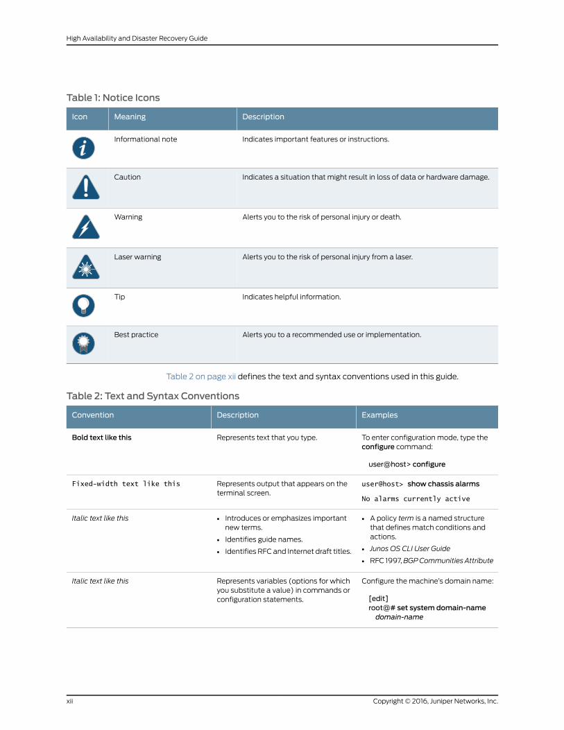
Table 1: Notice Icons
DescriptionMeaningIcon
Indicates important features or instructions.Informational note
Indicates a situation that might result in loss of data or hardware damage.Caution
Alerts you to the risk of personal injury or death.Warning
Alerts you to the risk of personal injury from a laser.Laser warning
Indicates helpful information.Tip
Alerts you to a recommended use or implementation.Best practice
Table 2 on page xii defines the text and syntax conventions used in this guide.
Table 2: Text and Syntax Conventions
ExamplesDescriptionConvention
To enter configuration mode, type theconfigure command:
user@host> configure
Represents text that you type.Bold text like this
user@host> show chassis alarms
No alarms currently active
Represents output that appears on theterminal screen.
Fixed-width text like this
• A policy term is a named structurethat defines match conditions andactions.
• Junos OS CLI User Guide
• RFC 1997,BGPCommunities Attribute
• Introduces or emphasizes importantnew terms.
• Identifies guide names.
• Identifies RFC and Internet draft titles.
Italic text like this
Configure the machine’s domain name:
[edit]root@# set system domain-namedomain-name
Represents variables (options for whichyou substitute a value) in commands orconfiguration statements.
Italic text like this
Copyright © 2016, Juniper Networks, Inc.xii
High Availability and Disaster Recovery Guide
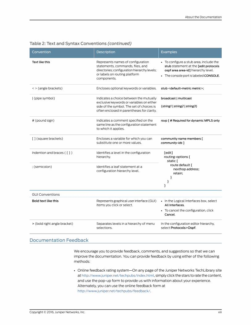
Table 2: Text and Syntax Conventions (continued)
ExamplesDescriptionConvention
• To configure a stub area, include thestub statement at the [edit protocolsospf area area-id] hierarchy level.
• The console port is labeledCONSOLE.
Represents names of configurationstatements, commands, files, anddirectories; configuration hierarchy levels;or labels on routing platformcomponents.
Text like this
stub <default-metricmetric>;Encloses optional keywords or variables.< > (angle brackets)
broadcast | multicast
(string1 | string2 | string3)
Indicates a choice between the mutuallyexclusive keywords or variables on eitherside of the symbol. The set of choices isoften enclosed in parentheses for clarity.
| (pipe symbol)
rsvp { # Required for dynamicMPLS onlyIndicates a comment specified on thesame line as the configuration statementto which it applies.
# (pound sign)
community namemembers [community-ids ]
Encloses a variable for which you cansubstitute one or more values.
[ ] (square brackets)
[edit]routing-options {static {route default {nexthop address;retain;
}}
}
Identifies a level in the configurationhierarchy.
Indention and braces ( { } )
Identifies a leaf statement at aconfiguration hierarchy level.
; (semicolon)
GUI Conventions
• In the Logical Interfaces box, selectAll Interfaces.
• To cancel the configuration, clickCancel.
Represents graphical user interface (GUI)items you click or select.
Bold text like this
In the configuration editor hierarchy,select Protocols>Ospf.
Separates levels in a hierarchy of menuselections.
> (bold right angle bracket)
Documentation Feedback
We encourage you to provide feedback, comments, and suggestions so that we can
improve the documentation. You can provide feedback by using either of the following
methods:
• Online feedback rating system—On any page of the Juniper Networks TechLibrary site
athttp://www.juniper.net/techpubs/index.html, simply click the stars to rate the content,
and use the pop-up form to provide us with information about your experience.
Alternately, you can use the online feedback form at
http://www.juniper.net/techpubs/feedback/.
xiiiCopyright © 2016, Juniper Networks, Inc.
About the Documentation
• E-mail—Send your comments to [email protected]. Include the document
or topic name, URL or page number, and software version (if applicable).
Requesting Technical Support
Technical product support is available through the Juniper Networks Technical Assistance
Center (JTAC). If you are a customer with an active J-Care or Partner Support Service
support contract, or are covered under warranty, and need post-sales technical support,
you can access our tools and resources online or open a case with JTAC.
• JTAC policies—For a complete understanding of our JTAC procedures and policies,
review the JTAC User Guide located at
http://www.juniper.net/us/en/local/pdf/resource-guides/7100059-en.pdf.
• Product warranties—For product warranty information, visit
http://www.juniper.net/support/warranty/.
• JTAC hours of operation—The JTAC centers have resources available 24 hours a day,
7 days a week, 365 days a year.
Self-Help Online Tools and Resources
For quick and easy problem resolution, Juniper Networks has designed an online
self-service portal called the Customer Support Center (CSC) that provides you with the
following features:
• Find CSC offerings: http://www.juniper.net/customers/support/
• Search for known bugs: http://www2.juniper.net/kb/
• Find product documentation: http://www.juniper.net/techpubs/
• Find solutions and answer questions using our Knowledge Base: http://kb.juniper.net/
• Download the latest versions of software and review release notes:
http://www.juniper.net/customers/csc/software/
• Search technical bulletins for relevant hardware and software notifications:
http://kb.juniper.net/InfoCenter/
• Join and participate in the Juniper Networks Community Forum:
http://www.juniper.net/company/communities/
• Open a case online in the CSC Case Management tool: http://www.juniper.net/cm/
To verify service entitlement by product serial number, use our Serial Number Entitlement
(SNE) Tool: https://tools.juniper.net/SerialNumberEntitlementSearch/
Opening a Casewith JTAC
You can open a case with JTAC on the Web or by telephone.
• Use the Case Management tool in the CSC at http://www.juniper.net/cm/.
• Call 1-888-314-JTAC (1-888-314-5822 toll-free in the USA, Canada, and Mexico).
Copyright © 2016, Juniper Networks, Inc.xiv
High Availability and Disaster Recovery Guide

For international or direct-dial options in countries without toll-free numbers, see
http://www.juniper.net/support/requesting-support.html.
xvCopyright © 2016, Juniper Networks, Inc.
About the Documentation

Copyright © 2016, Juniper Networks, Inc.xvi
High Availability and Disaster Recovery Guide
PART 1
High Availability
• Overview on page 3
• Understanding the High Availability Software Architecture on page 7
• Understanding the Junos Space Cluster (Fabric) Architecture on page 15
• Configuring High Availability Overview on page 27
• High Availability Failover Scenarios on page 33
1Copyright © 2016, Juniper Networks, Inc.

Copyright © 2016, Juniper Networks, Inc.2
High Availability and Disaster Recovery Guide
CHAPTER 1
Overview
• Junos Space High Availability Overview on page 3
• High Availability Characteristics of Junos Space Appliances on page 5
Junos Space High Availability Overview
Junos Space is designed as a carrier-grade system that provides a complete fault tolerant
solution. The set of topics describing Junos Space high availability (HA) provide an
overview of the Junos Space high availability design and implementation, as well as all
the steps that are required to deploy a high availability solution, from ordering your
appliances and preparing a Junos Space high availability cluster, to final deployment.
In order to gain an understanding of the Junos Space high availability solution, we
recommend that you read all the Junos Space high availability topics. However, if you
are primarily interested in setting up high availability, including the prerequisite steps,
see the “Configuring the Junos Space Cluster for High Availability Overview” on page 27
topic. If you are interested in high availability for network monitoring, see “High Availability
for Network Monitoring” on page 23. A set of frequently asked questions about Junos
Space high availability are also answered in Junos Space High Availability FAQ.
Junos Space Network Management Platform is available in two form factors:
• JA1500 or JA2500 carrier-grade hardware appliance
• Virtual appliance for the VMware ESX server or Kernel-based Virtual Machine (KVM)
environment
Both the Junos Space hardware appliance and virtual appliance use the same software
build with identical features to provide the complete package including OS, databases,
load balancers and JBoss engines. You can cluster multiple appliances together to form
a Junos Space cluster, as shown in Figure 1 on page 4.
3Copyright © 2016, Juniper Networks, Inc.
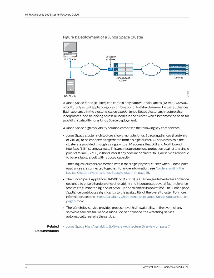
Figure 1: Deployment of a Junos Space Cluster
A Junos Space fabric (cluster) can contain only hardware appliances (JA1500, JA2500,
or both), only virtual appliances, or a combination of both hardware and virtual appliances.
Each appliance in the cluster is called a node. Junos Space cluster architecture also
incorporates load balancing across all nodes in the cluster, which becomes the basis for
providing scalability for a Junos Space deployment.
A Junos Space high availability solution comprises the following key components:
• Junos Space cluster architecture allows multiple Junos Space appliances (hardware
or virtual) to be connected together to form a single cluster. All services within the
cluster are provided through a single virtual IP address that GUI and Northbound
Interface (NBI) clients can use. This architecture provides protection against any single
point of failure (SPOF) in the cluster. If any node in the cluster fails, all services continue
to be available, albeit with reduced capacity.
Three logical clusters are formed within the single physical cluster when Junos Space
appliances are connected together. For more information, see “Understanding the
Logical Clusters Within a Junos Space Cluster” on page 15.
• The Junos Space Appliance (JA1500 or JA2500) is a carrier-grade hardware appliance
designed to ensure hardware-level reliability and incorporates several fault tolerance
features to eliminate single point of failure and minimize its downtime. The Junos Space
Appliance contributes significantly to the availability of the overall cluster. For more
information, see the “High Availability Characteristics of Junos Space Appliances” on
page 5 topic.
• The Watchdog service provides process-level high availability. In the event of any
software services failure on a Junos Space appliance, the watchdog service
automatically restarts the service.
RelatedDocumentation
Junos Space High Availability Software Architecture Overview on page 7•
Copyright © 2016, Juniper Networks, Inc.4
High Availability and Disaster Recovery Guide
High Availability Characteristics of Junos Space Appliances
Junos Space Appliances (JA1500 and JA2500) incorporate the following fault tolerance
features that prevent or minimize their downtime and contribute significantly to the
availability of the overall cluster:
• Hot-swappable hard disk drives managed by a RAID controller
• The JA1500 appliance has three hard drives in RAID 5 configuration and the JA2500
appliance has six hard drives in a RAID 10 configuration.
• The hot swappable hard drives on Junos Space appliances are externally accessible
in field replaceable trays, providing component high availability. You can remove
and replace a hard disk without powering off the appliance or disrupting any functions
performed by the appliance.
• The RAID controller manages the hard disk drives and presents them as logical units.
• Option to install a redundant power supply module—Junos Space Appliances are
shipped with a single AC power supply. However, you can install an additional power
supply module that serves as a redundant power supply if one power supply module
fails. If you install a second power supply module, ensure that you plug in each power
supply module into a separate power circuit.
When an appliance has an additional redundant, functioning power supply module
that is plugged into a separate power circuit, the power supply modules are
hot-swappable.
• Two cooling fans—Two externally accessible and hot-swappable cooling fans provide
the required airflow and cooling for the appliance.
For detailed information about Junos Space Appliances, refer to the Hardware
Documentation section of the Junos Space and Applications page.
RelatedDocumentation
• Junos Space High Availability Overview on page 3
5Copyright © 2016, Juniper Networks, Inc.
Chapter 1: Overview

Copyright © 2016, Juniper Networks, Inc.6
High Availability and Disaster Recovery Guide
CHAPTER 2
Understanding the High AvailabilitySoftware Architecture
• Junos Space High Availability Software Architecture Overview on page 7
• Software Components for Junos Space Nodes on page 11
Junos Space High Availability Software Architecture Overview
The Junos Space platform is designed to ensure five-nines availability with a clustered,
multi-tiered, distributed architecture comprising the following features:
• Standard browser-based Web 2.0 GUI clients and REST/HTTPS-based NBI clients
• Apache Load Balancer as a top-level load balancer
• JBoss Application Server based on J2EE technology to provide application framework
• MySQL database to manage persistent data
The following sections describe the Junos Space architecture and identify the basic
requirements for communication between nodes in a Junos Space cluster:
• Junos Space Software Architecture on page 7
• Load-Balancing Architecture on page 9
• Database Architecture on page 9
• Inter-Node Communication Among Nodes in a Junos Space Cluster on page 10
Junos Space Software Architecture
Figure 2 on page 8 provides a high-level view of the Junos Space software architecture.
Junos Space services are accessible to GUI and NBI clients by means of a single virtual
IP address for the cluster.
7Copyright © 2016, Juniper Networks, Inc.
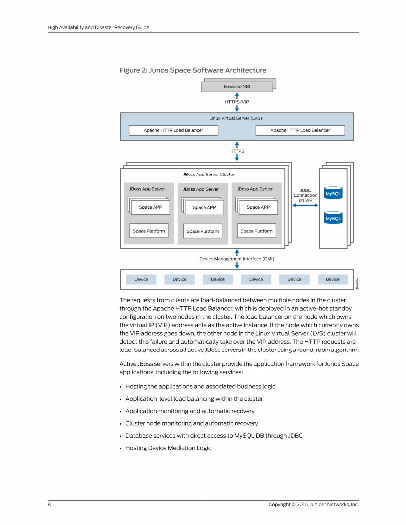
Figure 2: Junos Space Software Architecture
The requests from clients are load-balanced between multiple nodes in the cluster
through the Apache HTTP Load Balancer, which is deployed in an active-hot standby
configuration on two nodes in the cluster. The load balancer on the node which owns
the virtual IP (VIP) address acts as the active instance. If the node which currently owns
the VIP address goes down, the other node in the Linux Virtual Server (LVS) cluster will
detect this failure and automatically take over the VIP address. The HTTP requests are
load-balanced across all active JBoss servers in the cluster using a round-robin algorithm.
Active JBoss servers within the cluster provide the application framework for Junos Space
applications, including the following services:
• Hosting the applications and associated business logic
• Application-level load balancing within the cluster
• Application monitoring and automatic recovery
• Cluster node monitoring and automatic recovery
• Database services with direct access to MySQL DB through JDBC
• Hosting Device Mediation Logic
Copyright © 2016, Juniper Networks, Inc.8
High Availability and Disaster Recovery Guide
Load-Balancing Architecture
A Junos Space cluster is presented with two kinds of loads:
• Incoming requests from GUI and NBI clients
• Communication with managed devices
Junos Space is designed to load-balance incoming requests across all active nodes in
the cluster. Requests from GUI and NBI clients arrive as HTTP requests serviced by the
active instance of the Apache HTTP load balancer. The load balancer distributes the
requests to all active JBoss servers in the cluster using a round-robin algorithm. Sticky
sessions are utilized to ensure that all HTTP requests associated with a specific GUI
session are served by the same JBoss server during the lifetime of that session. For the
purpose of application-level load balancing, JBoss business logic processes complex
requests as a set of sub-jobs, which are distributed across multiple nodes in the cluster.
For example, a single request to a four-node Space cluster to resynchronize 100 devices
is divided into four sub-jobs that are executed on four different nodes, with each node
resynchronizing 25 devices. For a detailed overview of load balancing, see the topic
“Understanding the Logical Clusters Within a Junos Space Cluster” on page 15.
To perform device-level load balancing, Junos Space employs logic in the Device Mediation
Layer (DML) so that device connections are equally distributed across all active nodes
in the cluster. Device-level load balancing is performed during device discovery by
comparing the number of device connections served by individual nodes and selecting
the least loaded node. If any node goes down, all associated device connections are
distributed to the remaining active nodes in the cluster, thus preventing a node outage
from affecting device connectivity. For a detailed overview of device connectivity
management, see the topic “Understanding High Availability Management of DMI
Connections” on page 22.
Database Architecture
MySQL Enterprise Edition is used to provide database services for managing persistent
data for both platform and applications. MySQL DB servers are running on two nodes in
the cluster in active-standby configuration. Database transactions are replicated between
the two MySQL servers in near real time. For information about the MySQL cluster that
is formed within each Junos Space cluster, see “Understanding the Logical Clusters Within
a Junos Space Cluster” on page 15.
Junos Space platform also incorporates network monitoring for fault and performance
management, which uses the PostgreSQL relational database service for storing fault
and performance related data. The PostgreSQL server runs on two nodes in the Space
cluster in active-active configuration with real-time replication to ensure that fault and
performance data continues to be available even if one of these nodes fail. For more
information, see “High Availability for Network Monitoring” on page 23.
9Copyright © 2016, Juniper Networks, Inc.
Chapter 2: Understanding the High Availability Software Architecture
Inter-Node Communication Among Nodes in a Junos Space Cluster
In order to facilitate seamless communication between the nodes in a Space cluster and
to achieve optimum performance of the cluster, you need to ensure the following:
• All nodes in a Junos Space cluster are configured with IP addresses inside the same
subnet. This is important for the VIP switchover mechanism to work correctly.
• All nodes in a Space cluster are connected by means of a 1-Gbps or 100-Mbps local
network with negligible latency.
• JBoss servers within a Junos Space cluster communicate by means of a UDP multicast
to form logical clusters.
NOTE: UDPmulticast traffic must be allowedwithin the nodes in thecluster, which alsomeans that you should disable IGMP snooping on theswitches that interconnect the cluster or configure themexplicitly to allowUDPmulticast between the nodes.
RelatedDocumentation
Junos Space High Availability Overview on page 3•
• Software Components for Junos Space Nodes on page 11
• Understanding the Logical Clusters Within a Junos Space Cluster on page 15
Copyright © 2016, Juniper Networks, Inc.10
High Availability and Disaster Recovery Guide
Software Components for Junos Space Nodes
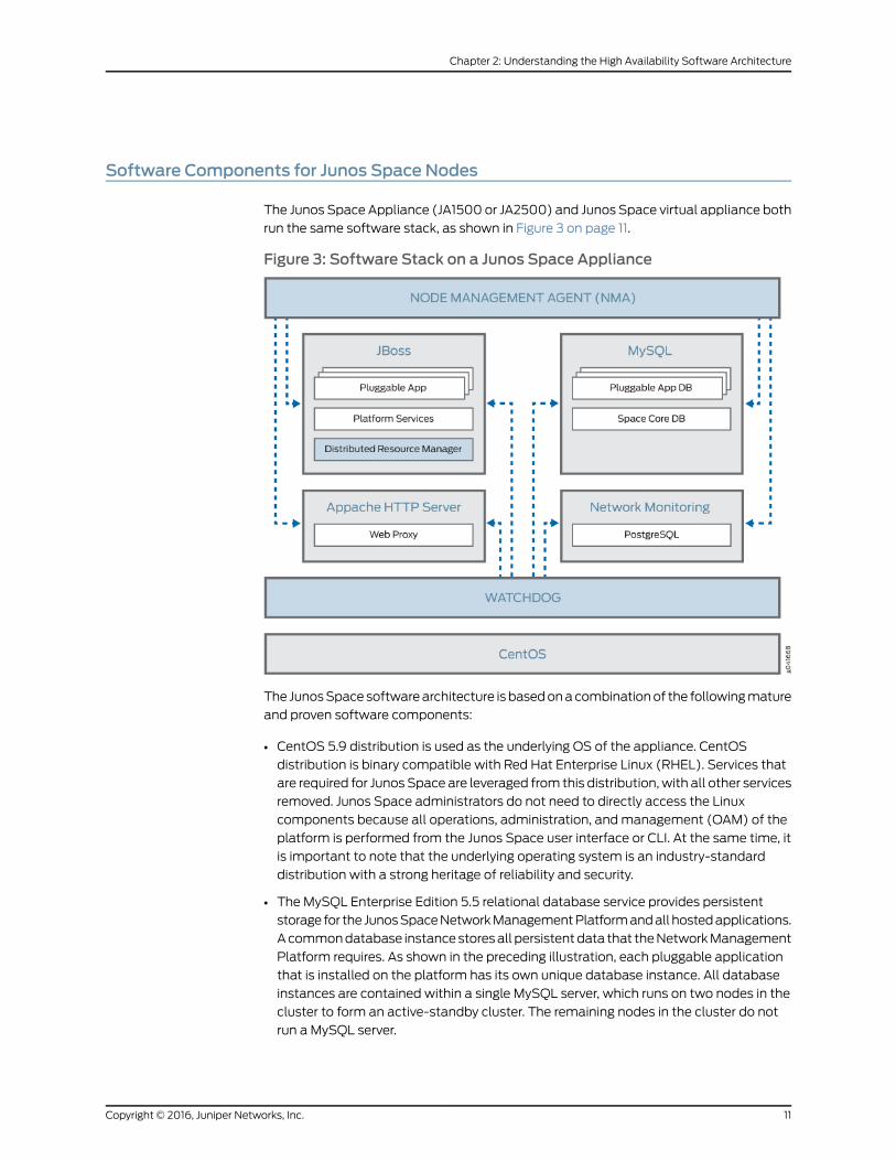
The Junos Space Appliance (JA1500 or JA2500) and Junos Space virtual appliance both
run the same software stack, as shown in Figure 3 on page 11.
Figure 3: Software Stack on a Junos Space Appliance
The Junos Space software architecture is based on a combination of the following mature
and proven software components:
• CentOS 5.9 distribution is used as the underlying OS of the appliance. CentOS
distribution is binary compatible with Red Hat Enterprise Linux (RHEL). Services that
are required for Junos Space are leveraged from this distribution, with all other services
removed. Junos Space administrators do not need to directly access the Linux
components because all operations, administration, and management (OAM) of the
platform is performed from the Junos Space user interface or CLI. At the same time, it
is important to note that the underlying operating system is an industry-standard
distribution with a strong heritage of reliability and security.
• The MySQL Enterprise Edition 5.5 relational database service provides persistent
storage for the Junos Space Network Management Platform and all hosted applications.
A common database instance stores all persistent data that the Network Management
Platform requires. As shown in the preceding illustration, each pluggable application
that is installed on the platform has its own unique database instance. All database
instances are contained within a single MySQL server, which runs on two nodes in the
cluster to form an active-standby cluster. The remaining nodes in the cluster do not
run a MySQL server.
11Copyright © 2016, Juniper Networks, Inc.
Chapter 2: Understanding the High Availability Software Architecture

• JBoss 7.1 Application Server is the container that hosts the presentation layer, business
logic layer, and data access layer of Junos Space platform as well as the hosted
applications. One JBoss server runs on each node in the cluster and they all work
together as a single load-sharing cluster.
• Apache HTTP Server (version 2.2.21) is the front-end load balancer for all requests
coming from GUI and NBI clients. This server runs on two nodes in the cluster which
together form an active-standby cluster.
• Network monitoring services are provided using OpenNMS, which is an award winning,
enterprise-grade network monitoring platform developed under the open source model.
OpenNMS is integrated into the Junos Space Network Management Platform Network
Monitoring workspace and provides fault monitoring and performance monitoring
features. Junos Space uses PostgreSQL as the relational database server for persisting
fault and performance data.
The following software components or services also play a significant role in the overall
management of a Junos Space cluster:
• Distributed Resource Manager (DRM)—DRM is deployed as a service inside the JBoss
application server, just like all other services provided by Network Management Platform
and the hosted applications. You can think of DRM as the server-side component that
you interact with when you navigate to the NetworkManagement Platform >
Administration > Fabric workspace in the Junos Space user interface. DRM works
together with the Node Management Agent to fulfill the following responsibilities:
• Managing the Junos Space cluster—DRM implements the business logic for adding
and removing nodes in the cluster and monitors the overall health of the cluster.
• Managing the logical clusters in the cluster—The logical clusters within the physical
cluster formed by the Junos Space nodes include the Apache Load Balancer cluster,
JBoss cluster, and Database cluster. DRM implements the business logic to add and
remove nodes in these logical clusters and monitors their status. The logical clusters
are described in detail in “Understanding the Logical Clusters Within a Junos Space
Cluster” on page 15.
• Node Management Agent (NMA)—NMA runs on each node in the cluster and is deployed
as a set of CGI scripts run by an Apache HTTP daemon. NMA has the following
responsibilities:
• Monitor system resource usage on the node and the health of various services running
on the node.
• Start and stop services on the node based on requests from DRM.
• Manage the configuration files for various services running on the node.
• Manage installation, uninstallation, and upgrades of pluggable applications as well
as upgrade of the Network Management Platform software on the node.
• Watchdog—The watchdog service (jmp-watchdog) runs on each node in the cluster
to ensure that required services on the node are running. Every second, the watchdog
checks that the required services are running and if the watchdog detects that a service
is down, it restarts the service.
Copyright © 2016, Juniper Networks, Inc.12
High Availability and Disaster Recovery Guide

RelatedDocumentation
• Junos Space High Availability Overview on page 3
• Junos Space High Availability Software Architecture Overview on page 7
• Understanding the Logical Clusters Within a Junos Space Cluster on page 15
13Copyright © 2016, Juniper Networks, Inc.
Chapter 2: Understanding the High Availability Software Architecture

Copyright © 2016, Juniper Networks, Inc.14
High Availability and Disaster Recovery Guide
CHAPTER 3
Understanding the Junos Space Cluster(Fabric) Architecture
• Understanding the Logical Clusters Within a Junos Space Cluster on page 15
• Understanding Virtual IP Availability Within a Junos Space Cluster on page 19
• Understanding High Availability Nodes in a Cluster on page 21
• Understanding High Availability Management of DMI Connections on page 22
• High Availability for Network Monitoring on page 23
• Understanding How Devices Are Configured to Send SNMP Traps to Junos
Space on page 25
Understanding the Logical ClustersWithin a Junos Space Cluster
You can connect multiple Junos Space appliances (hardware or virtual) together to form
a Junos Space cluster. Figure 4 on page 16 shows the logical clusters (Apache Load
Balancer cluster, the JBoss cluster, and MySQL cluster) that are formed within each Junos
Space cluster.
15Copyright © 2016, Juniper Networks, Inc.
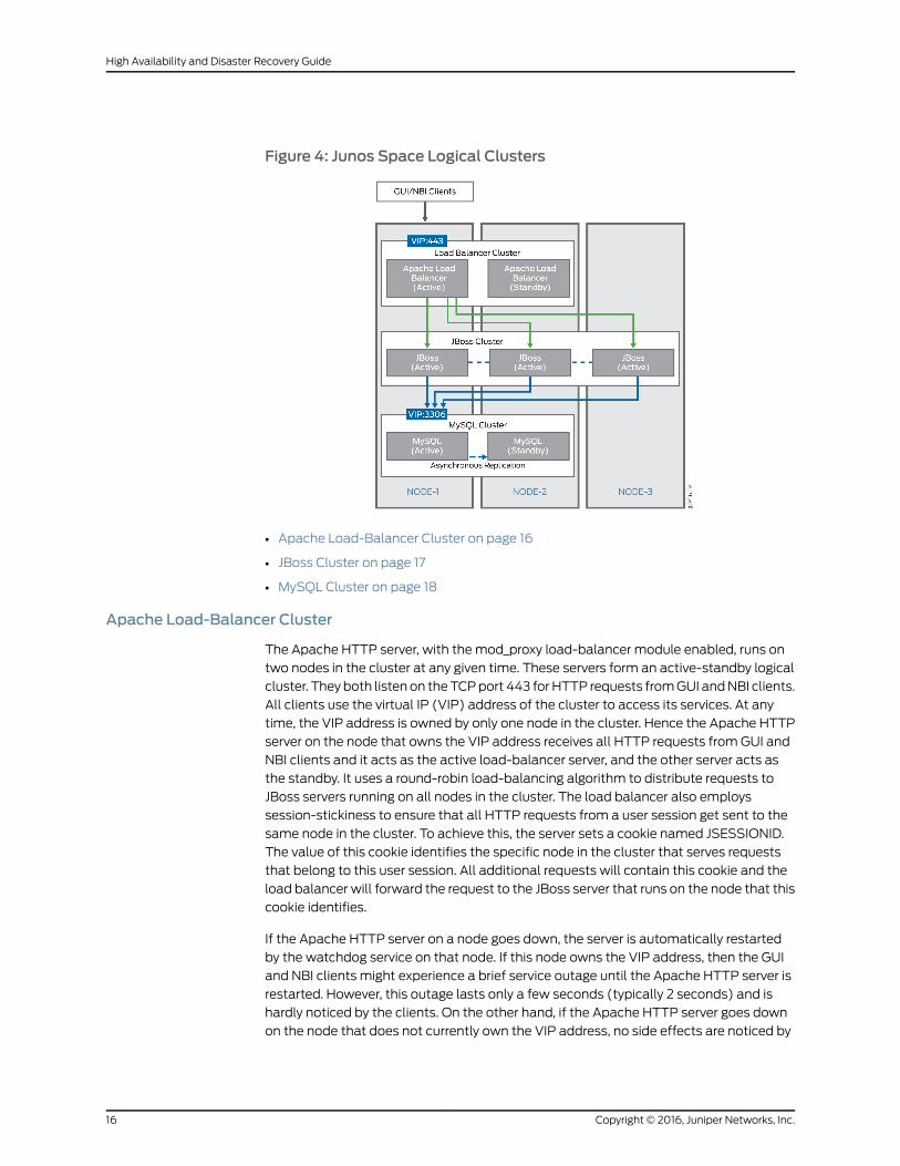
Figure 4: Junos Space Logical Clusters
• Apache Load-Balancer Cluster on page 16
• JBoss Cluster on page 17
• MySQL Cluster on page 18
Apache Load-Balancer Cluster
The Apache HTTP server, with the mod_proxy load-balancer module enabled, runs on
two nodes in the cluster at any given time. These servers form an active-standby logical
cluster. They both listen on the TCP port 443 for HTTP requests from GUI and NBI clients.
All clients use the virtual IP (VIP) address of the cluster to access its services. At any
time, the VIP address is owned by only one node in the cluster. Hence the Apache HTTP
server on the node that owns the VIP address receives all HTTP requests from GUI and
NBI clients and it acts as the active load-balancer server, and the other server acts as
the standby. It uses a round-robin load-balancing algorithm to distribute requests to
JBoss servers running on all nodes in the cluster. The load balancer also employs
session-stickiness to ensure that all HTTP requests from a user session get sent to the
same node in the cluster. To achieve this, the server sets a cookie named JSESSIONID.
The value of this cookie identifies the specific node in the cluster that serves requests
that belong to this user session. All additional requests will contain this cookie and the
load balancer will forward the request to the JBoss server that runs on the node that this
cookie identifies.
If the Apache HTTP server on a node goes down, the server is automatically restarted
by the watchdog service on that node. If this node owns the VIP address, then the GUI
and NBI clients might experience a brief service outage until the Apache HTTP server is
restarted. However, this outage lasts only a few seconds (typically 2 seconds) and is
hardly noticed by the clients. On the other hand, if the Apache HTTP server goes down
on the node that does not currently own the VIP address, no side effects are noticed by
Copyright © 2016, Juniper Networks, Inc.16
High Availability and Disaster Recovery Guide
any clients or any other components. The watchdog service restarts the server and it
comes back up in about 2 seconds.
JBoss Cluster
The JBoss application server runs on all nodes except dedicated database nodes in the
Junos Space cluster. The nodes form a single all-active logical cluster and the
load-balancer server (described previously) distributes the load across all the nodes.
Even if one or more of the JBoss servers in the cluster fails, the application logic still
continues to be accessible from the surviving nodes. Jboss servers on all nodes are started
with the same configuration, and use UDP multicast to detect each other and form the
single cluster. JBoss also uses UDP multicast for session replication and caching services
across all the nodes.
NOTE: The JBoss server does not run on FMPM nodes and hosted virtualmachines.
When the JBoss server on a node goes down, other nodes in the JBoss cluster will detect
this change and automatically re-configure themselves to remove the failed node from
the cluster. The time taken by other cluster members to detect a failed JBoss server
depends on whether the JBoss server process crashed abnormally or is non-responsive.
In the former case, cluster members will detect the failure immediately (around 2 seconds)
because their TCP connections to the crashed JBoss server are closed by the operating
system. In the latter case, cluster members will detect the failure in about 52 seconds.
If a JBoss server crashes, it will be restarted automatically by the watchdog service
(jmp-watchdog) running on the node. When the JBoss server comes back up, it will be
automatically discovered by other cluster members and added to the cluster. The JBoss
server will then synchronize its cache from the other nodes in the cluster. The typical
restart time for JBoss is 2 to 5 minutes, but it can take more time depending on the number
of apps installed, the number of devices being managed, the number of DMI schema
versions installed, and so forth.
One JBoss server in the cluster will always act as the master of the cluster. The main
purpose of the master designation is to host services that are deployed as cluster-wide
singletons (HA singletons); for example, services that must be deployed on only one
server in the cluster at any time. Junos Space uses a several services of this type, including
the Job Poller service, which provides a single timer for scheduling jobs across the cluster,
and the Distributed Resource Manager (DRM) service, which monitors and manages the
nodes in the cluster. These services are deployed only on the JBoss server that is
designated as the master.
NOTE: This does not mean that themaster does not host other services.Non-cluster singleton services are also hosted on themaster server. JunosSpace is configured such that the first JBoss server that comes up in thecluster becomes themaster. If themaster server goes down, othermembersin the JBoss cluster detect this and elect a newmaster.
17Copyright © 2016, Juniper Networks, Inc.
Chapter 3: Understanding the Junos Space Cluster (Fabric) Architecture
MySQL Cluster
The MySQL server runs on two nodes in the Junos Space cluster at any given time. These
nodes form a logical active-standby cluster and both nodes listen on TCP port 3306 for
database requests from JBoss servers. By default, JBoss servers are configured to use
the Virtual IP (VIP) address of the cluster to access database services. At any time, the
VIP address is owned by only one node in the cluster. Thus, the MySQL server on the node
that owns the VIP address receives all database requests from JBoss and this server acts
as the active database server, and the other server acts as the standby.
If you want to improve the performance of Junos Space Network Management Platform
and Junos Space applications, you can add two Junos Space nodes to run as dedicated
database nodes. When you add any two Junos Space nodes as the primary and secondary
database nodes, the MySQL server is moved to the two dedicated database nodes and
is disabled on the first two nodes of the Junos Space cluster. This frees system resources
on the Junos Space active VIP node, improving the performance of the node.
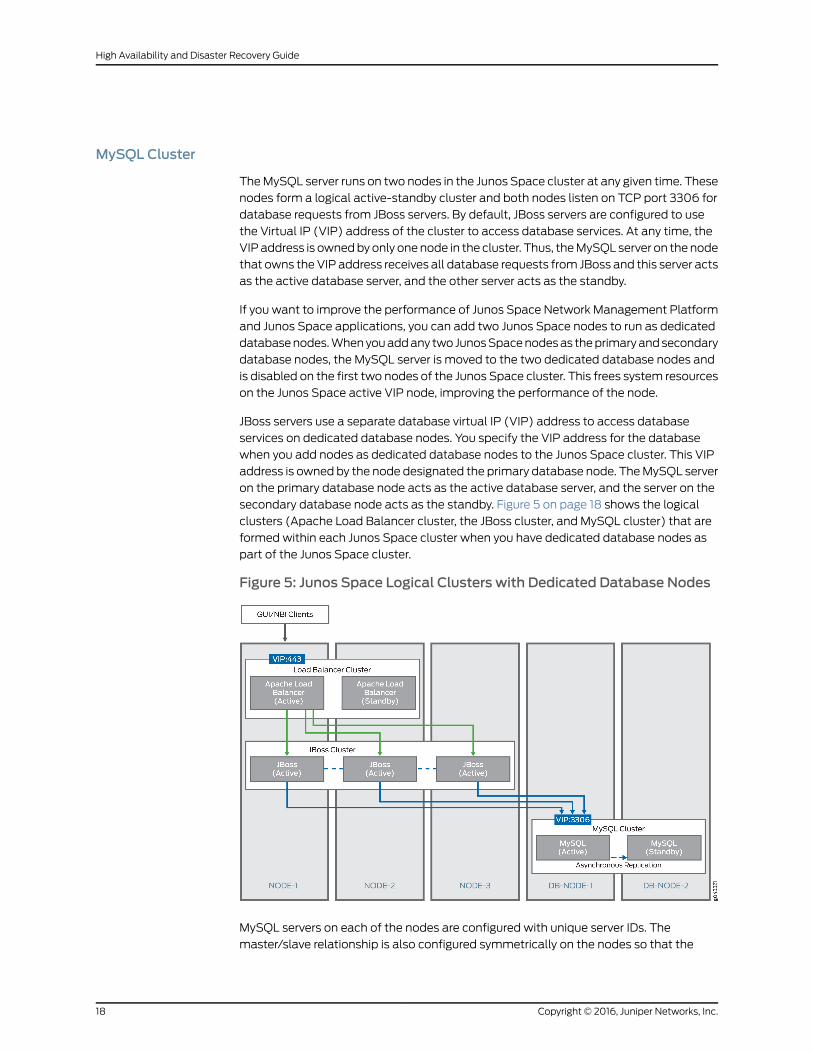
JBoss servers use a separate database virtual IP (VIP) address to access database
services on dedicated database nodes. You specify the VIP address for the database
when you add nodes as dedicated database nodes to the Junos Space cluster. This VIP
address is owned by the node designated the primary database node. The MySQL server
on the primary database node acts as the active database server, and the server on the
secondary database node acts as the standby. Figure 5 on page 18 shows the logical
clusters (Apache Load Balancer cluster, the JBoss cluster, and MySQL cluster) that are
formed within each Junos Space cluster when you have dedicated database nodes as
part of the Junos Space cluster.
Figure 5: Junos Space Logical Clusters with Dedicated Database Nodes
MySQL servers on each of the nodes are configured with unique server IDs. The
master/slave relationship is also configured symmetrically on the nodes so that the
Copyright © 2016, Juniper Networks, Inc.18
High Availability and Disaster Recovery Guide
server on the first node is configured with the second node as the master; and the server
on the second node is configured with the first node as the master. Thus both nodes are
capable of acting as a slave to the other, and the server running on the node which owns
the VIP address acts as the master at any time, which ensures that the master-slave
relationship switches dynamically as the VIP ownership switches from one node to the
other. All transactions committed on the active (master) server are replicated to the
standby (slave) server in near real time, by means of the asynchronous replication solution
[2] provided by MySQL, which is based on the binary logging mechanism. The MySQL
server operating as the master (the source of the database changes) writes updates and
changes as “events” to the binary log. The information in the binary log is stored in different
logging formats according to the database changes that are recorded. The slave server
is configured to read the binary log from the master and to execute all the events in the
binary log on the slave's local database.
If the MySQL server on a node goes down, the server is restarted automatically by the
watchdog service on that node. Once restarted, the MySQL server should come up within
20 to 60 seconds. If this node owns the VIP address, JBoss might experience a brief
database outage for this 20 to 60 second duration. Any requests which require database
access will fail during this period. On the other hand, if the MySQL server goes down on
the node that does not currently own the VIP address, there are no side effects noticed
by JBoss. The watchdog service restarts the server and it comes back up in less than 1
minute. Once the server is back up, it will resynchronize with the master in the background
and the resynchronization time will depend on the number of changes that occurred
during the outage.
RelatedDocumentation
Understanding Virtual IP Availability Within a Junos Space Cluster on page 19•
• Understanding High Availability Nodes in a Cluster on page 21
• Configuring the Junos Space Cluster for High Availability Overview on page 27
Understanding Virtual IP AvailabilityWithin a Junos Space Cluster
Junos Space must ensure that the virtual IP (VIP) address is always available on one of
the nodes in the cluster. This is essential for the HA solution because if the VIP address
becomes unavailable, the entire cluster becomes unavailable to all user interface clients
and NBI clients. To protect against this scenario, Junos Space uses the heartbeat service
(version 2.1.3 to version 3) provided by the Linux-HA project to ensure that the VIP address
is always available on one of the nodes in the cluster. For information about the Linux-HA
project, see the Linux HA User Guide.
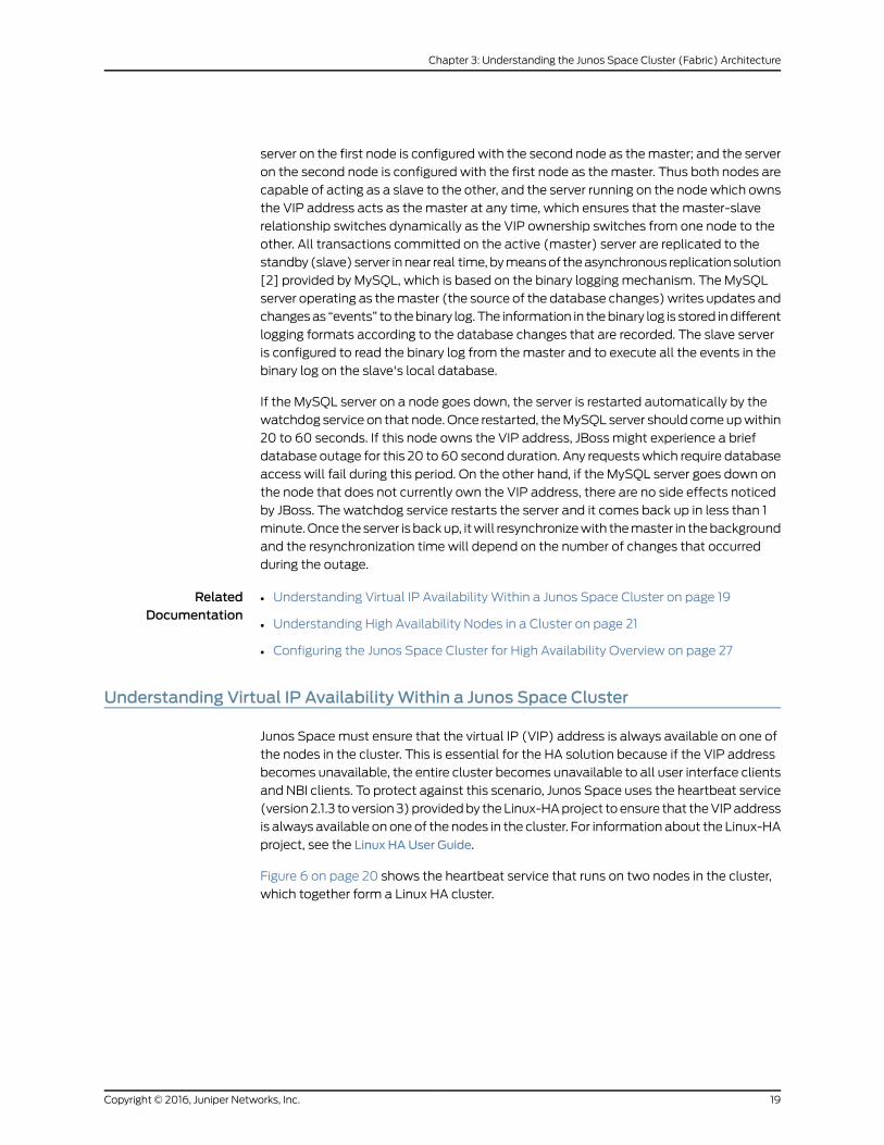
Figure 6 on page 20 shows the heartbeat service that runs on two nodes in the cluster,
which together form a Linux HA cluster.
19Copyright © 2016, Juniper Networks, Inc.
Chapter 3: Understanding the Junos Space Cluster (Fabric) Architecture
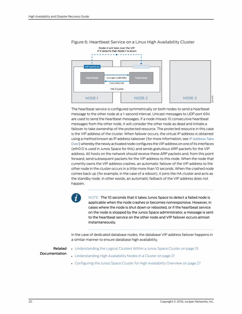
Figure 6: Heartbeat Service on a Linux High Availability Cluster
The heartbeat service is configured symmetrically on both nodes to send a heartbeat
message to the other node at a 1-second interval. Unicast messages to UDP port 694
are used to send the heartbeat messages. If a node misses 10 consecutive heartbeat
messages from the other node, it will consider the other node as dead and initiate a
failover to take ownership of the protected resource. The protected resource in this case
is the VIP address of the cluster. When failover occurs, the virtual IP address is obtained
using a method known as IP address takeover (for more information, see IP Address Take
Over) whereby the newly activated node configures the VIP address on one of its interfaces
(eth0:0 is used in Junos Space for this) and sends gratuitous ARP packets for the VIP
address. All hosts on the network should receive these ARP packets and, from this point
forward, send subsequent packets for the VIP address to this node. When the node that
currently owns the VIP address crashes, an automatic failover of the VIP address to the
other node in the cluster occurs in a little more than 10 seconds. When the crashed node
comes back up (for example, in the case of a reboot), it joins the HA cluster and acts as
the standby node. In other words, an automatic failback of the VIP address does not
happen.
NOTE: The 10 seconds that it takes Junos Space to detect a failed node isapplicable when the node crashes or becomes nonresponsive. However, incases where the node is shut down or rebooted, or if the heartbeat serviceon the node is stopped by the Junos Space administrator, a message is sentto the heartbeat service on the other node and VIP failover occurs almostinstantaneously.
In the case of dedicated database nodes, the database VIP address failover happens in
a similar manner to ensure database high availability.
RelatedDocumentation
Understanding the Logical Clusters Within a Junos Space Cluster on page 15•
• Understanding High Availability Nodes in a Cluster on page 21
• Configuring the Junos Space Cluster for High Availability Overview on page 27
Copyright © 2016, Juniper Networks, Inc.20
High Availability and Disaster Recovery Guide

Understanding High Availability Nodes in a Cluster
A Junos Space cluster must include at least two nodes to achieve high availability (HA).
If the cluster includes more than two nodes, the availability of the cluster does not
increase, but the amount of load that the cluster can handle increases with each node
added to the cluster. So at any given time, only two nodes in the cluster provide HA to
the whole cluster. By default, these two nodes alone (referred to as the HA nodes in the
cluster) form the Linux HA cluster, the Apache Load Balancer cluster, and the MySQL
cluster. If you have added dedicated database nodes to the cluster, the MySQL cluster
is formed by the primary and secondary database nodes.
By default, the first two nodes added to the cluster function as the HA nodes. In the topic
“Understanding the Logical Clusters Within a Junos Space Cluster” on page 15, the
example shows that the first two nodes (Node-1 and Node-2) are HA nodes. If you were
to delete Node-1 or Node-2 from the NetworkManagement Platform > Administration >
Fabric workspace, the system checks to see if other nodes in the cluster are available to
replace the deleted HA node. The system then displays the list of capable nodes (only
Node-3 in the example), which you can select. After you confirm the selected node, the
Distributed Resource Manager (DRM) service adds the node to the HA cluster by sending
requests to the Node Management Agent (NMA) running on the newly selected node.
The following actions are initiated on the node added to the HA cluster:
• Apache HTTP server with the mod_proxy load balancer is started on the node and the
node is configured with all JBoss nodes as members.
• If there are no dedicated database nodes in the cluster, the database from the MySQL
server on the other HA node in the cluster is copied and the MySQL server is started
on the node. This server is configured as a slave of the other MySQL server in the cluster
and it resynchronizes with the master in the background. The existing MySQL server is
also reconfigured to act as a slave of this new server to ensure a symmetric master/slave
configuration on both.
When you add dedicated database nodes to the Junos Space cluster, you add two nodes
together as the primary and secondary database nodes to form the MySQL cluster. The
database is copied from the active HA node to the two database nodes and is disabled
on the HA nodes. If you were to delete one of the database nodes from the cluster, the
other database node is designated the primary database node. The system checks
whether non-HA nodes in the cluster are available to replace the deleted database node
and displays the list of nodes you can select to replace the deleted node.
After you select a node, the Distributed Resource Manager (DRM) service adds the node
to the MySQL cluster by sending requests to the Node Management Agent (NMA) running
on the newly selected node.
The following actions are initiated on the node added to the MySQL cluster:
• The database from the MySQL server on the primary database node in the cluster is
copied and the MySQL server is started on the newly-added secondary database node.
This server is configured as a slave of the MySQL server on the primary database node
and it resynchronizes with the master in the background. The existing MySQL server
21Copyright © 2016, Juniper Networks, Inc.
Chapter 3: Understanding the Junos Space Cluster (Fabric) Architecture

on the primary database node is also reconfigured to act as a slave of this new server
on the secondary database node to ensure a symmetric master/slave configuration
on both.
• The JBoss server is stopped on the newly added database node.
RelatedDocumentation
Understanding the Logical Clusters Within a Junos Space Cluster on page 15•
• Configuring the Junos Space Cluster for High Availability Overview on page 27
Understanding High Availability Management of DMI Connections
Junos Space maintains a persistent device management interface (DMI) connection with
each managed device and supports the following types of DMI connections:
• Space-initiated (default)—A TCP connection from a JBoss server process on a node
to the SSH port (22 by default) on the device.
• Device-initiated—A TCP connection from the device to port 7804 on a JBoss server
process on a node.
To load balance DMI connections, all connections are distributed across all the nodes in
a Junos Space cluster. A device keepalive monitor sends a heartbeat message to devices
every 40 seconds. If there is no reply for 15 minutes, the device keepalive monitor marks
the connection status of the device as Down.
A device connection monitor scans the connection status of all devices with
space-initiated connections. If the monitor detects that the connection status of a device
is Down, it attempts to reconnect to the device. If this first attempt fails, a second attempt
is made after 30 minutes. Because each reconnect attempt is performed from a node in
the cluster that is the least loaded in terms of the number of devices managed, the device
might get reconnected from a different node in the cluster after a connection failure.
When devices are discovered using device-initiated connection mode, the device
management IP address of all nodes in the Junos Space cluster gets configured in the
outbound SSH stanza on the device. The device will keep trying to connect to one of
these IP addresses until one succeeds. The device is responsible for detecting any failures
on the connection and for reconnecting to another node in the cluster. For more
information, see the Junos XML Management Protocol Guide.
If a JBoss server process crashes or is stopped, or if the node running the process is shut
down, all the DMI connections that it maintains are migrated to another node in the
cluster. When this JBoss server comes up, these DMI connections are not automatically
migrated back to the JBoss server because it is available for any new devices that are
being discovered. At present, there is no way to migrate DMI connections back to this
original JBoss server, which can result in poor load balancing of DMI connections if there
are not many new devices to be discovered.
RelatedDocumentation
Understanding High Availability Nodes in a Cluster on page 21•
Copyright © 2016, Juniper Networks, Inc.22
High Availability and Disaster Recovery Guide
High Availability for Network Monitoring
The type of Junos Space cluster you create determines how high availability for the
network monitoring service functions. A Junos Space fabric without Fault Monitoring and
Performance Monitoring (FMPM) nodes uses the two high availability (HA) nodes in the
cluster to protect the network monitoring service against node failures. However, when
a Junos Space fabric includes one or more FMPM nodes, network monitoring functionality
is disabled on the Junos Space nodes and enabled on the FMPM nodes.
This topic includes the following sections:
• High-Availability Fabric without FMPM Nodes on page 23
• High-Availability Fabric with FMPM Nodes on page 24
High-Availability Fabric without FMPMNodes
When a Junos Space fabric does not include FMPM nodes, the Junos Space cluster
employs a hot-standby solution that uses the two high availability (HA) nodes in the
cluster to protect the network monitoring service against node failures.
Figure 7 on page 23 shows how network monitoring runs on two HA nodes in the cluster
to protect the service in the event of node failure.
Figure 7: Linux High Availability Cluster
The network monitoring service is automatically installed on all nodes in the cluster.
However, at any time, the network monitoring service runs only on the node that currently
owns the virtual IP (VIP) address, and the service is responsible for all fault management
and performance management functionality for the entire cluster. Network monitoring
uses PostgreSQL 9.1 database for its storage needs. As Figure 7 on page 23 shows,
real-time streaming replication with continuous archiving is set up between the two HA
nodes (Node-1 and Node-2 in the cluster), which ensures that the network monitoring
database on the standby node is continuously in sync with the network monitoring
database on the active node. In addition, a cron job runs on the active node once a day
at midnight to synchronize the network monitoring file system to the standby node, which
ensures that all back-end configuration files that network monitoring uses are also
synchronized between the two HA nodes.
23Copyright © 2016, Juniper Networks, Inc.
Chapter 3: Understanding the Junos Space Cluster (Fabric) Architecture

When a VIP failover to the standby node occurs, network monitoring is automatically
started on the node. The network monitoring service takes approximately 3 to 5 minutes
to complete its initialization before it performs all fault monitoring and performance
monitoring functionality for the cluster. Consequently, Junos Space users can expect a
network monitoring outage to last approximately 3 to 5 minutes.
The watchdog service on the two HA nodes is responsible for ensuring that the network
monitoring service is running on the HA node that owns the virtual IP address and is not
running on the other (standby) HA node. As already noted, the watchdog service checks
the status of all services on the node every second. If the watchdog service detects that
the node owns the VIP address but does not run the network monitoring service, the
watchdog service starts the network monitoring service and creates the cron job to
synchronize fault management and performance management data to the other node.
If the watchdog service detects that the node does not own the VIP address but is running
the network monitoring service, the watchdog service shuts down the service and removes
the cron job entry for data synchronization.
High-Availability Fabric with FMPMNodes
If you manage a large or complex network, you might want to dedicate all your
performance and network monitoring functionality to a special node called the Fault
Monitoring and Performance Monitoring (FMPM) node. When you create a Junos Space
fabric with one or more FMPM nodes, network monitoring functionality is disabled on all
the Junos Space nodes and enabled on the FMPM nodes. When the first FMPM node is
added to the fabric, network monitoring functionality is enabled on this node and the
PostgreSQL 9.1 database runs on this node.
When you add a second FMPM node to the fabric, the first FMPM node functions as the
primary node, and the second FMPM node functions as the standby node. The network
monitoring service is automatically installed on both FMPM nodes in the FMPM team.
However, at any time, the network monitoring service runs only on the FMPM node that
currently owns the VIP address, and the service is responsible for all fault management
(FM) and performance management (PM) functionality for the FMPM team. Network
monitoring uses PostgreSQL 9.1 database for its storage needs.
Real-time streaming replication with continuous archiving is set up between the two
FMPM nodes in the team, which ensures that the network monitoring database on the
standby node is continuously in sync with the network monitoring database on the active
node. In addition, a cron job runs on the active FMPM node once a day at midnight to
synchronize the network monitoring file system to the standby FMPM node, which ensures
that all back-end configuration files that network monitoring uses are also synchronized
between the two FMPM nodes. When a VIP failover to the standby FMPM node occurs,
network monitoring is automatically started on the second FMPM node. The network
monitoring service takes approximately 3 to 5 minutes to complete its initialization before
it performs all FM and PM functionality for the FMPM team. Consequently, Junos Space
users can expect a network monitoring outage to last approximately 3 to 5 minutes.
The watchdog service on the two nodes is responsible for ensuring that the network
monitoring service is running on the FMPM node which owns the virtual IP address and
is not running on the other (standby) FMPM node. As already noted, the watchdog service
checks the status of all services on the active FMPM node every second. If the watchdog
Copyright © 2016, Juniper Networks, Inc.24
High Availability and Disaster Recovery Guide
service detects that the FMPM node owns the VIP address but does not run the network
monitoring service, the watchdog service starts the network monitoring service and
creates the cron job to synchronize fault management and performance management
data to the other node. If the watchdog service detects that the FMPM node does not
own the VIP address but is running the network monitoring service, the watchdog service
shuts down the service and removes the cron job entry for data synchronization.
RelatedDocumentation
Understanding How Devices Are Configured to Send SNMP Traps to Junos Space on
page 25
•
• Understanding High Availability Nodes in a Cluster on page 21
• Configuring the Junos Space Cluster for High Availability Overview on page 27
Understanding HowDevices Are Configured to Send SNMP Traps to Junos Space
Devices discovered in Junos Space are automatically configured to send SNMP traps to
Junos Space.
The trap destination IP address that is configured on devices depends on whether a
separate device management interface (eth3) is used on the node on which network
monitoring is currently running. If the node uses the eth3 interface for device management,
then the discovered devices are configured with the eth3 IP address. Otherwise, the
discovered devices are configured with the virtual IP (VIP) address of the Junos Space
cluster. If the VIP is configured as the trap destination, you do not need to reconfigure
the trap destination on managed devices after a VIP failover because network monitoring
will be started automatically on the node that currently owns the VIP and the node will
start receiving the traps. However, if the eth3 IP address is configured as the trap
destination, you must reconfigure all devices when a VIP failover occurs. This will be done
automatically as part of the startup process of network monitoring on the second HA
node. When network monitoring comes up on the new node, the trap destination on all
managed devices will be automatically reconfigured to be the eth3 IP address for this
node.
NOTE: Automatic reconfiguration is not possible for devices whoseconnection with Junos Space is down at the time of the networkmonitoringfailover. If there are any such devices, networkmonitoring stops receivingtraps from these devices after the failover, and you will need tomanuallychange the trap destination on these devices to the eth3 IP address of thenode where networkmonitoring is currently running.
RelatedDocumentation
• High Availability for Network Monitoring on page 23
• Understanding High Availability Nodes in a Cluster on page 21
25Copyright © 2016, Juniper Networks, Inc.
Chapter 3: Understanding the Junos Space Cluster (Fabric) Architecture

Copyright © 2016, Juniper Networks, Inc.26
High Availability and Disaster Recovery Guide
CHAPTER 4
Configuring High Availability Overview
• Configuring the Junos Space Cluster for High Availability Overview on page 27
Configuring the Junos Space Cluster for High Availability Overview
This topic provides an overview of the key steps required to configure a Junos Space
cluster as a carrier-grade system with all high-availability capabilities enabled.
• Requirements on page 27
• Preparation on page 28
• Configuring the First Node in the Cluster on page 30
• Adding a Second Node to the Cluster on page 30
• Adding Additional Nodes to a Cluster on page 31
• Configuring FMPM Nodes on page 31
• Removing Nodes from a Cluster on page 31
Requirements
You can choose either Junos Space Appliances (JA1500 or JA2500) or Virtual Appliances
for setting up a Junos Space cluster.
For a cluster of Virtual Appliances, the following recommendations apply for the underlying
virtualization infrastructure on which the appliances are deployed:
• Use VMware ESX server 4.0 or later or VMware ESXi server 4.0, 5.0, 5.1, or 5.5, or a
kernel-based virtual machine (KVM) server on qemu-kvm (KVM) Release
0.12.1.2-2/448.el6 or later (which is on CentOS Release 6.5) that can support a virtual
machine.
• Deploy the two Junos Space Virtual Appliances (JSVA) on two separate servers.
• Each server must be able to dedicate 4 vCPUs or 2.66 GHz or more, 32 GB RAM, and
sufficient hard disk for the Junos Space Virtual Appliance that it hosts.
• The servers should have similar fault tolerance features as the Junos Space appliance:
dual redundant power supplies connected to two separate power circuits, RAID array
of hard disks for storage, and hot-swappable fans.
27Copyright © 2016, Juniper Networks, Inc.
NOTE: For more information on the requirements for the virtual appliance,refer to the Deploying a Junos Space Virtual Appliance on a VMware ESX orVMware ESXi Server andDeploying a Junos Space Virtual Appliance on a KVMServer topics in the Junos Space Virtual Appliance documentation.
If you choose Junos Space appliances, you need to choose two instances of the
corresponding SKUs for the appliance that you are using. In addition, order a second
power supply module for each appliance in order to provide the redundant power supply
module for each appliance.
Preparation
We recommend you use the following guidelines as you prepare a Junos Space cluster
for high availability:
• The Junos Space cluster architecture allows you to dedicate one or two nodes solely
for fault monitoring and performance monitoring functions. These are known as Fault
Monitoring and Performance Monitoring (FMPM) nodes and are recommended when
managing complex networks with a large number of devices and interfaces to be
monitored. The advantage of this architecture is that fault and performance monitoring
functions are localized within the FMPM nodes and the rest of the Junos Space nodes
are freed up for other functions. One of the first decisions that you must make is
whether to use FMPM nodes in your Junos Space cluster. If you choose to deploy
FMPM nodes, we recommended that you have two of them so that the fault monitoring
and performance monitoring services also have high availability. Currently, load
balancing is not implemented across multiple FMPM nodes, so there is no need to
have more than two FMPM nodes in a cluster.
• The Junos Space cluster architecture allows you to dedicate two Junos Space nodes
solely for MySQL database functions. Dedicated database nodes can free up system
resources such as CPU time and memory utilization on the Junos Space VIP node,
thereby improving the performance of the Junos Space VIP node. If you decide to add
dedicated database nodes to the Junos Space cluster, in the first instance you must
add two nodes together as the primary and secondary database nodes, enabling
database high availability by default.
• A Junos Space appliance (hardware or virtual) utilizes two Ethernet interfaces: eth0
and eth3. The eth0 interface is used for all inter-node communication within the
cluster and also for communication between GUI and NBI clients and the cluster. The
eth3 interface can be configured as the device management interface, in which case,
all communication between the cluster and the managed devices occur over this
interface. If the eth3 interface is not configured, all device communication also takes
place over the eth0 interface. So, you must first decide whether or not to use eth3 as
the device management interface. If you choose to use eth3, you should use eth3 for
all appliances in the same cluster.
Copyright © 2016, Juniper Networks, Inc.28
High Availability and Disaster Recovery Guide
• You also must decide on the following networking parameters to be configured on
the Junos Space appliances:
• IP address and subnet mask for the interface “eth0”, the default gateway address,
and the address of one or more name servers in the network.
• IP address and subnet mask for the interface “eth3” if you choose to use a separate
device management interface.
• The virtual IP address to use for the cluster, which should be an address in the same
subnet as the IP address assigned to the “eth0” interface.
If you decide to add dedicated database nodes, you must choose a separate virtual
IP (VIP) address in the same subnet as the VIP address of the Junos Space cluster.
This database VIP address must be in the same subnet as the IP address assigned
to the eth0 Ethernet interface and must be different from the VIP address of the
Junos Space cluster and the FMPM nodes.
If you decide to use an FMPM cluster, you must choose a separate virtual IP address
for the FMPM nodes. Please note that the FMPM virtual IP address need not be in
the same subnet as the virtual IP address of the Junos Space nodes.
• NTP server settings from which to synchronize the appliance’s time.
• The IP address that you assign to each Junos Space node in the cluster and the virtual
IP address for the cluster must be in the same subnet. This is required for the IP address
takeover mechanism to function correctly.
It is possible to configure the FMPM nodes in a separate subnet.
NOTE: Strictly speaking, you can choose to deploy the non HA nodes ina different subnet. However, doing so will cause a problem if one of theHA nodes goes down and youwant to promote one of the other nodes asan HA node. So, we recommend that you configure eth0 on all nodes inthe same subnet.
• Because JBoss servers on all the nodes communicate using UDP multicast to form
and manage the JBoss cluster, you must ensure that UDP multicast is enabled in the
network where you deploy the cluster nodes. You must also disable IGMP snooping
on the switches interconnecting the cluster, or configure them explicitly to allow UDP
multicast between the nodes.
NOTE: FMPM nodes and dedicated database nodes do not participate inthe JBoss cluster. Therefore, there is no need to enable UDPmulticastbetween these nodes and the Junos Space nodes in the cluster.
29Copyright © 2016, Juniper Networks, Inc.
Chapter 4: Configuring High Availability Overview
Configuring the First Node in the Cluster
After you power on the appliance and connect to its console, Junos Space displays a
menu-driven command-line interface (CLI) that you use to specify the initial configuration
of the appliance. To complete this initial configuration, you specify the following
parameters:
• IP address and subnet mask for the interface “eth0”
• IP address of the default gateway
• IP address of the name server
• IP address and subnet mask for the interface “eth3”, if you choose to configure a cluster
as described in the topic “Understanding the Logical Clusters Within a Junos Space
Cluster” on page 15.
• Whether this appliance being added to an existing cluster. Choose “n” to indicate that
this is the first node in the cluster.
• The virtual IP address that the cluster will use.
• NTP server settings from which to synchronize the appliance’s time.
• Maintenance mode user ID and password.
NOTE: Make note of the user ID and password that you specify formaintenancemode, as you will need this ID and password to performNetwork Management Platform software upgrades and databaserestoration.
For detailed step-by-step instructions on configuring the appliance for initial deployment,
refer to the Junos Space appliance documentation. After you have completed the initial
configuration, all Junos Space services are started on the appliance and you can log in
to the Network Management Platform User Interface from the virtual IP address assigned
to it. At this stage, you have a single node cluster with no HA, which you can see by
navigating to the NetworkManagement Platform > Administration> Fabric workspace.
Adding a Second Node to the Cluster
In order to add a second node to the cluster, you must first configure the second appliance
using its console. The process is identical to that of the first appliance except that you
need to choose “y” when it you are prompted to specify whether this appliance will be
added to an existing cluster. Make sure that the IP address you assign to this node is in
the same subnet as the first node. You must also ensure its uniformity in using a separate
device management interface (eth3). If you chose to use eth3 for the first node, choose
the same for all additional nodes in the cluster.
After you configure the second appliance, you can log in to the Network Management
Platform user interface of the first node at its virtual IP address to add the node to the
cluster from the NetworkManagement Platform > Administration > Fabric > Add Fabric
Node workspace. To add the node to the cluster, specify the IP address assigned to the
Copyright © 2016, Juniper Networks, Inc.30
High Availability and Disaster Recovery Guide
eth0 interface of the new node, assign a name for the new node, and (optionally) schedule
the date and time to add the node. The Distributed Resource Manager (DRM) service
running on the first node contacts Node Management Agent (NMA) on the new node to
make necessary configuration changes and add it to the cluster. The DRM service also
ensures that required services are started on this node. After the new node joins the
cluster, you can monitor its status from the NetworkManagement Platform >
Administration > Fabric workspace.
For more information about adding nodes to an existing cluster from the Junos Space
Platform UI, see Fabric Management Overview (in the Junos Space Network Management
PlatformWorkspaces Feature Guide).
Adding Additional Nodes to a Cluster
The process for adding additional nodes is identical to the process for adding the second
node. However, these additional nodes do not participate in any of the HA clusters in the
fabric, unless explicitly promoted to that role if another HA node is removed, or if they
are added as dedicated database nodes to form the MySQL cluster.
For more information about adding nodes to an existing cluster from the Junos Space
Platform UI, see Fabric Management Overview (in the Junos Space Network Management
PlatformWorkspaces Feature Guide).
Configuring FMPMNodes
You can configure up to 2 FMPM nodes in a cluster. To configure FMPM nodes:
• For Junos Space appliances, refer to the following topics in theHardwareDocumentation
section of the Junos Space Network Management Platform documentation:
• Configuring a Junos Space Appliance as a Standalone or Primary FMPM Node
• Configuring a Junos Space Appliance as a Backup or Secondary FMPM Node for High
Availability
• For Junos Space Virtual Appliances, refer to the following topics in the Junos Space
Virtual Appliance documentation:
• Configuring a Junos Space Virtual Appliance as a Standalone or Primary FMPM Node
• Configuring a Junos Space Virtual Appliance as a Backup or Secondary FMPM Node
for High Availability
Removing Nodes from a Cluster
If a node has failed and needs to be replaced, you can easily remove the node from the
cluster. Navigate to the NetworkManagement Platform > Administration > Fabric
workspace, select the node you want to remove, and choose the Delete Node action. If
the node being deleted is an HA node, the system will check if other nodes in the cluster
can be elected as the replacement for the HA node being deleted. The system then shows
the list of capable nodes (only Node-3 in this example) and allows you to choose from
the available nodes. The process is described in “Understanding High Availability Nodes
in a Cluster” on page 21.
31Copyright © 2016, Juniper Networks, Inc.
Chapter 4: Configuring High Availability Overview

If the node being deleted is a database node, the system checks whether other nodes in
the cluster can replace the database node being deleted. If there are nodes present that
are capable of replacing the deleted node, the system displays the list of capable nodes
and allows you to choose from the available nodes.
For more information about deleting nodes from the cluster, see Deleting a Node from
the Junos Space Fabric (in the Junos Space Network Management PlatformWorkspaces
Feature Guide).
RelatedDocumentation
• Understanding High Availability Failover Scenarios on page 33
Copyright © 2016, Juniper Networks, Inc.32
High Availability and Disaster Recovery Guide
CHAPTER 5
High Availability Failover Scenarios
• Understanding High Availability Failover Scenarios on page 33
Understanding High Availability Failover Scenarios
The following sections describe the possible high availability failure scenarios, how they
are detected, provides recovery actions, and if applicable, explains any impact to the
system as a result of the failure.
• Active VIP Node Crashes on page 33
• Standby VIP Node Crashes on page 34
• eth0 on the Active VIP Node Goes Down on page 35
• eth0 on the Standby VIP Node Goes Down on page 35
• A Non-VIP Node Crashes on page 36
• eth0 on a Non-VIP Node Goes Down on page 36
• eth3 on a Non-VIP Node Goes Down on page 37
• eth3 on the Active VIP Node Goes Down on page 37
• JBoss Server on a Node Goes Down on page 38
• MySQL Server on the Active VIP Node Goes Down on page 38
• MySQL Server on the Standby VIP Node Goes Down on page 39
• Primary Database Node Crashes on page 39
• Secondary Database Node Crashes on page 40
• MySQL Server on the Primary Database Node Goes Down on page 40
• MySQL Server on the Secondary Database Node Goes Down on page 40
• Apache HTTP Server on the Active VIP Node Goes Down on page 41
• Apache HTTP Server on the Standby VIP Node Goes Down on page 41
Active VIP Node Crashes
Detection
The heartbeat service running on the standby VIP node detects the crash within 10
seconds as it will not receive any heartbeat messages from its peer. The JBoss clustering
33Copyright © 2016, Juniper Networks, Inc.

mechanism will enable JBoss servers on the other nodes to detect that the JBoss server
on the failed node is unresponsive, in about 52 seconds.
Recovery
The standby node immediately takes over the VIP address.
Device connections served by the failed node will be migrated to the remaining nodes in
the cluster. This process will start about 1 minute after the JBoss cluster members detect
that the JBoss server on the failed node is down. The time it takes to complete will depend
on the number of device connections to be migrated, the load on the remaining nodes,
and so on. It is expected to complete within a couple of minutes.
After the VIP address is taken over by the standby node, network monitoring service is
started on the standby node. It takes around 3 to 5 minutes for network monitoring service
to complete its initialization. It might take more time depending on the size of FM and
PM data that is being maintained.
Impact
The VIP address will be unavailable for about 10 seconds until it is taken over by the
standby node. GUI/API client access during this brief period will encounter transient
errors. Also any SNMP traps sent by the devices to the VIP address during this interval
will be lost.
Device connectivity will be down for a couple of minutes for the devices whose
connections were being served by the JBoss server on the failed node.
Any jobs that were in progress on the failed node will be marked as failed with a reason
stating that the node was down.
Users will experience an outage of network monitoring functionality for about 3 to 5
minutes while the network monitoring service is being initialized on the standby node.
Standby VIP Node Crashes
Detection
JBoss clustering mechanism will enable JBoss servers on the other nodes to detect that
the JBoss server on the failed node is non-responsive in about 52 seconds.
Recovery
Device connections served by the failed node are migrated to the remaining nodes in the
cluster. This process starts about 1 minute after the JBoss cluster members detect that
the JBoss server on the failed node is down. The process completion time depends on
the number of device connections to be migrated, the load on the remaining nodes, etc,
but should complete within a few minutes.
Impact
Device connectivity will be down for a couple of minutes for the devices whose
connections were being served by the JBoss server on the failed node.
Copyright © 2016, Juniper Networks, Inc.34
High Availability and Disaster Recovery Guide

Any jobs that were in-progress on the failed node are marked as failed with the reason
that the node was down.
eth0 on the Active VIP Node Goes Down
Detection
The heartbeat service running on the standby VIP node detects the crash within 10
seconds as it will not receive any heartbeat messages from its peer. The JBoss clustering
mechanism will enable JBoss servers on the other nodes to detect that the JBoss server
on the failed node is unresponsive, in about 52 seconds.
Recovery
The standby node immediately takes over the VIP address.
Device connections served by the failed node will be migrated to the remaining nodes in
the cluster. This process will start about 1 minute after the JBoss cluster members detect
that the JBoss server on the failed node is down. The time it takes to complete will depend
on the number of device connections to be migrated, the load on the remaining nodes,
and so on. It is expected to complete within a couple of minutes.
After the VIP address is taken over by the standby node, network monitoring service is
started on the standby node. It takes around 3 to 5 minutes for network monitoring service
to complete its initialization. It might take more time depending on the size of FM and
PM data that is being maintained.
Impact
The VIP address will be unavailable for about 10 seconds until it is taken over by the
standby node. GUI/API client access during this brief period will encounter transient
errors. Also any SNMP traps sent by the devices to the VIP address during this interval
will be lost.
Device connectivity will be down for a couple of minutes for the devices whose
connections were being served by the JBoss server on the failed node.
Any jobs that were in progress on the failed node will be marked as failed with a reason
stating that the node was down.
Users will experience an outage of network monitoring functionality for about 3 to 5
minutes while the network monitoring service is being initialized on the standby node.
eth0 on the Standby VIP Node Goes Down
Detection
JBoss clustering mechanism will enable JBoss servers on the other nodes to detect that
the JBoss server on the failed node is non-responsive in about 52 seconds.
Recovery
Device connections served by the failed node are migrated to the remaining nodes in the
cluster. This process starts about 1 minute after the JBoss cluster members detect that
35Copyright © 2016, Juniper Networks, Inc.
Chapter 5: High Availability Failover Scenarios

the JBoss server on the failed node is down. The process completion time depends on
the number of device connections to be migrated, the load on the remaining nodes, etc,
but should complete within a few minutes.
Impact
Device connectivity will be down for a couple of minutes for the devices whose
connections were being served by the JBoss server on the failed node.
Any jobs that were in-progress on the failed node are marked as failed with the reason
that the node was down.
ANon-VIP Node Crashes
Detection
The JBoss clustering mechanism enables JBoss servers on the other nodes to detect that
the JBoss server on the failed node is non-responsive in about 52 seconds.
Recovery
Device connections served by the failed node will be migrated to the remaining nodes in
the cluster. This process will start about one minute after the JBoss cluster members
detect that the JBoss server on the failed node is down. The time it takes to complete
depends on the number of device connections to be migrated, the load on the remaining
nodes, and so on. This should complete within a couple of minutes.
Impact
Device connectivity will be down for a couple of minutes for the devices whose
connections were served by the JBoss server on the failed node. Any jobs that were
in-progress on the failed node are marked as failed with a reason stating that the node
was down.
eth0 on a Non-VIP Node Goes Down
Detection
JBoss clustering mechanism will enable JBoss servers on the other nodes to detect that
the JBoss server on the failed node is non-responsive in about 52 seconds.
Recovery
Device connections served by the failed node are migrated to the remaining nodes in the
cluster. This process starts about 1 minute after the JBoss cluster members detect that
the JBoss server on the failed node is down. The process completion time depends on
the number of device connections to be migrated, the load on the remaining nodes, etc,
but should complete within a few minutes.
Impact
Device connectivity will be down for a couple of minutes for the devices whose
connections were being served by the JBoss server on the failed node.
Copyright © 2016, Juniper Networks, Inc.36
High Availability and Disaster Recovery Guide

Any jobs that were in-progress on the failed node are marked as failed with the reason
that the node was down.
eth3 on a Non-VIP Node Goes Down
Detection
The device keepalive monitor detects that all device connections served by this node are
down in 15 minutes, and marks the connection status of these devices as Down.
Recovery
For Junos Space initiated connections, Junos Space will attempt to reconnect to these
devices. Each attempt is made from the cluster node that is determined to be the least
loaded in terms of the number of devices it manages. If other nodes in the cluster are
significantly less loaded than this node according to this load-balancing check,
reconnection attempts are made from those nodes and they will succeed. In this case,
connectivity for these devices comes back up in a couple of minutes. If this node happens
to be the least loaded, then all reconnection attempts are made from this node and these
attempts will continue failing as long as eth3 remains down.
In the case of device initiated connections, the device detects a connection failure in
about 15 minutes, and then reconnects to another node in the cluster in the next few
seconds.
Impact
Device connectivity will be down for the devices whose connections were being served
by this node. Connectivity might be down for 15 minutes (best case) or until eth3 is brought
back up (worst case). Also, the outage time might vary from device to device depending
on which node is chosen to attempt a reconnection for that device. In the case of
device initiated connections, the outage will last for a little more than 15 minutes.
eth3 on the Active VIP Node Goes Down
Detection
The device keepalive monitor detects that all device connections served by this node are
down in 15 minutes, and marks the connection status of these devices as Down.
Recovery
For Junos Space initiated connections, Junos Space will attempt to reconnect to these
devices. Each attempt is made from the cluster node that is determined to be the least
loaded in terms of the number of devices it manages. If other nodes in the cluster are
significantly less loaded than this node according to this load-balancing check,
reconnection attempts are made from those nodes and they will succeed. In this case,
connectivity for these devices comes back up in a couple of minutes. If this node happens
to be the least loaded, then all reconnection attempts are made from this node and these
attempts will continue failing as long as eth3 remains down.
37Copyright © 2016, Juniper Networks, Inc.
Chapter 5: High Availability Failover Scenarios

In the case of device initiated connections, the device detects a connection failure in
about 15 minutes, and then reconnects to another node in the cluster in the next few
seconds.
Impact
Device connectivity will be down for the devices whose connections were being served
by this node. Connectivity might be down for 15 minutes (best case) or until eth3 is brought
back up (worst case). Also, the outage time might vary from device to device depending
on which node is chosen to attempt a reconnection for that device. In the case of
device initiated connections, the outage will last for a little more than 15 minutes.
The network monitoring service is also impacted because it runs only on the VIP node.
The service will not receive any SNMP traps from any managed device because all devices
are configured with the eth3 IP address of the VIP node as the trap destination. Also, all
performance and fault monitoring of all managed devices will fail until eth3 is brought
back up.
JBoss Server on a Node Goes Down
Detection
When the JBoss server on a node goes down, other nodes in the JBoss cluster will detect
this immediately (around 2 seconds) as it results in their TCP connections to the crashed
JBoss server getting closed by the operating system.
Recovery
Device connections served by the crashed JBoss server will be migrated to the other
nodes in the cluster. This process will start about 1 minute after the JBoss cluster members
detect that the JBoss server on the failed node is down. The time it takes to complete
will depend on the number of device connections to be migrated, the load on the remaining
nodes, and so on. It is expected to complete within a couple of minutes.
The watchdog service (jmp watchdog) running on the node will detect that JBoss server
is down and restarts it automatically. When the JBoss server comes back up, it will be
automatically discovered by other cluster members and get added to the cluster. It will
then synchronize its cache from the other nodes in the cluster. The typical restart time
for JBoss is 2 to 5 minutes. However, it can take more time depending on the number of
apps installed, the number of devices being managed, the number of DMI schema versions
installed, and so on.
Impact
Device connectivity will be down for a couple of minutes for the devices whose
connections were being served by the JBoss server that went down.
Any jobs that were in progress on the crashed JBoss server will be marked as failed with
a reason stating that the node was down.
MySQL Server on the Active VIP Node Goes Down
Detection
Copyright © 2016, Juniper Networks, Inc.38
High Availability and Disaster Recovery Guide
If the MySQL server on a node goes down, the watchdog service detects the down MySQL
server on that active node in about 1 to 2 seconds.
Recovery
The watchdog service will immediately restart MySQL server on the node. Once restarted,
the MySQL server comes up in around 20 to 60 seconds.
Impact
The MySQL server on the VIP node is the active database servicing all requests from all
JBoss servers in the cluster. This effectively means that a brief database outage could
be experienced by JBoss on all nodes for this duration (20 to 60 seconds). Any requests
that require database access will fail during this period. This will result in failures
encountered by GUI/API clients on their requests which internally require database access
during this period. This will also result in failures of jobs that require database access
during this period.
MySQL Server on the Standby VIP Node Goes Down
Detection
If the MySQL server on a node goes down, the watchdog service detects the down MySQL
server on that standby node in about 1 to 2 seconds.
Recovery
The watchdog service will immediately restart MySQL server on the node. Once restarted,
it takes around 20 to 60 seconds for the MySQL server to come up. Once it is back up,
this server will resynchronize with the master in the background and the resynchronization
time will depend on the number of changes that happened during the outage.
Impact
Since the MySQL server on the standby VIP node is not accessed by JBoss, its down time
does not cause any adverse impact that is noticed by the rest of the system or users of
the system.
Primary Database Node Crashes
Detection
The heartbeat service running on the secondary database node detects the crash within
10 seconds as it does not receive any heartbeat messages from the primary database
node.
Recovery
The database VIP address is transferred to the secondary database node within 10 to
20 seconds. The JBoss servers on other nodes can access the database after the database
VIP address is taken over by the secondary database node.
Impact
39Copyright © 2016, Juniper Networks, Inc.
Chapter 5: High Availability Failover Scenarios
The database VIP address becomes unavailable for about 10 to 20 seconds until it is
taken over by the secondary database node.The MySQL server on the primary database
node is the active database servicing all requests from all JBoss servers in the cluster.
This effectively means that a brief database outage could be experienced by JBoss on
all nodes for this duration (20 to 60 seconds). Any requests that require database access
fail during this period. This results in failures encountered by GUI and API clients on their
requests that internally require database access during this period. This also results in
failures of jobs that require database access during this period.
Secondary Database Node Crashes
Detection
The heartbeat service running on the primary database node detects the crash within 10
seconds as it does not receive any heartbeat messages from the secondary database
node.
Recovery
The node can be deleted and a new node can be added to the Junos Space cluster as a
secondary database node to maintain database high availability.
Impact
Because the MySQL server on the secondary database node is not accessed by JBoss,
its downtime does not cause any adverse impact that is noticed by the rest of the system
or users of the system.
MySQL Server on the Primary Database Node Goes Down
Detection
If the MySQL server on a node goes down, the watchdog service detects the down MySQL
server on that active node in about 1 to 2 seconds.
Recovery
The watchdog service immediately restarts the MySQL server on the node. When restarted,
the MySQL server comes up in around 20 to 60 seconds.
Impact
The MySQL server on the primary database node is the active database servicing all
requests from all JBoss servers in the cluster. This effectively means that a brief database
outage could be experienced by JBoss on all nodes for this duration (20 to 60 seconds).
Any requests that require database access fail during this period. This results in failures
encountered by GUI and API clients on their requests that internally require database
access during this period. This also results in failures of jobs that require database access
during this period.
MySQL Server on the Secondary Database Node Goes Down
Detection
Copyright © 2016, Juniper Networks, Inc.40
High Availability and Disaster Recovery Guide
If the MySQL server on a node goes down, the watchdog service detects the down MySQL
server on that standby node in about 1 to 2 seconds.
Recovery
The watchdog service immediately restarts the MySQL server on the node. When restarted,
it takes around 20 to 60 seconds for the MySQL server to come up. After it is back up,
this server resynchronizes with the master in the background. The resynchronization time
depends on the number of changes that happened during the outage.
Impact
Because the MySQL server on the secondary database node is not accessed by JBoss,
its downtime does not cause any adverse impact that is noticed by the rest of the system
or users of the system.
Apache HTTP Server on the Active VIP Node Goes Down
Detection
If the Apache HTTP server on a node goes down, the watchdog service detects the down
HTTP server on that node in about 1 to 2 seconds.
Recovery
The watchdog service will immediately restart the Apache HTTP server on the node and
it becomes ready for service in 1 second.
Impact
A brief service outage could be experienced by GUI and NBI clients until the Apache HTTP
server is restarted. However, this outage is only for a few seconds (typically 2 seconds)
and is hardly noticed by the clients.
Apache HTTP Server on the Standby VIP Node Goes Down
Detection
If the Apache HTTP server on a node goes down, the watchdog service detects the down
HTTP server on that node in about 1 to 2 seconds.
Recovery
The watchdog service will immediately restart Apache HTTP Server on the node and it
becomes ready for service in 1 second.
Impact
No impact.
RelatedDocumentation
• Configuring the Junos Space Cluster for High Availability Overview on page 27
• Disaster Recovery Overview on page 45
41Copyright © 2016, Juniper Networks, Inc.
Chapter 5: High Availability Failover Scenarios

Copyright © 2016, Juniper Networks, Inc.42
High Availability and Disaster Recovery Guide
PART 2
Disaster Recovery
• Disaster Recovery Solution on page 45
• Configuring the Disaster Recovery Process on page 73
• Managing the Disaster Recovery Solution on page 87
43Copyright © 2016, Juniper Networks, Inc.

Copyright © 2016, Juniper Networks, Inc.44
High Availability and Disaster Recovery Guide
CHAPTER 6
Disaster Recovery Solution
• Disaster Recovery Overview on page 45
• Understanding the Normal Operation of Active and Standby Sites on page 64
• Understanding Disaster Recovery Failure Scenarios on page 66
• Understanding How the Standby Site Becomes Operational When the Active Site Goes
Down on page 71
Disaster Recovery Overview
A Junos Space cluster allows you to maintain high availability and scalability in your
network management solution. However, because all nodes in a cluster need to be within
the same subnet, they are typically deployed in the same data center or within the same
campus. But you can easily recover a cluster from a disaster at a location by mirroring
the original Junos Space installation on a cluster to another cluster at a geographically
different location. So if the main Junos Space site fails due to a disaster such as an
earthquake, the other site can take over. Hence, the physical installation of the disaster
recovery setup is typically a set of two geographically separate clusters: the active or
main site (that is, the local site) and the standby or backup site (that is, the remote site).
When the basic connectivity requirements and prerequisites are met (refer to
“Prerequisites to Configure Disaster Recovery” on page 48 and “Connectivity Requirements
to Configure Disaster Recovery” on page 48 ), data from the cluster at the active site is
replicated to the cluster at the standby site in near realtime.
The data in the MySQL and PgSQL databases is replicated asynchronously from the
active site to the standby site over an SSL connection. MySQL and PgSQL data between
the disaster recovery sites is encrypted using self-signed SSL certificates that are
generated when disaster recovery is initialized. CA root certificate, CRLs, user certificates,
scripts, device images, archived audit logs, and information about scheduled jobs are
replicated to the standby site during the real-time data replication to the standby site.
The configuration and round-robin database (RRD) files are synchronized periodically
by using Secure Copy Protocol (SCP) from the active site to the standby site.
The disaster recovery watchdog, an in-built Junos Space mechanism, monitors the
integrity of database replication across sites. All other services (such as JBoss, OpenNMS,
Apache, and so on) do not run on the standby site until the active site fails over to the
standby site. A failover to the standby site is automatically initiated when the active site
is down. A device arbitration algorithm is used to determine which site should be the
45Copyright © 2016, Juniper Networks, Inc.
active site to prevent a split-brain scenario where both sites try to be active. For
information about the device arbitration algorithm, see “Failure Detection by Using the
Device Arbitration Algorithm” on page 51.
The following sections describe the connectivity requirements for the disaster recovery
process, failure-detection mechanisms, and the disaster recovery commands:
• Disaster Recovery Solution on page 46
• Prerequisites to Configure Disaster Recovery on page 48
• Connectivity Requirements to Configure Disaster Recovery on page 48
• Disaster Recovery Watchdog on page 49
• Failure Detection by Using the Device Arbitration Algorithm on page 51
• Failure Detection by Using the Custom Failure-Detection Scripts on page 53
• Steps to Configure Disaster Recovery on page 61
• Disaster Recovery Commands on page 61
Disaster Recovery Solution
After you configure and initiate the disaster recovery process between an active site and
a standby site, asynchronous replication of MySQL and PgSQL database between the
sites is initiated. Configuration and RRD files are backed up to the standby site through
SCP at defined time intervals.
During the normal operation of the disaster recovery solution, the GUI and API users and
the managed devices are connected to the active site for all network management
services. The connectivity between the standby site and managed devices is disabled
as long as the active site is functional. When the active site becomes unavailable due to
a disaster, the standby site becomes operational. At this time, all services on the standby
site are started and the connectivity between the standby site and managed devices is
established.
Figure 8 on page 47 displays the disaster recovery solution.
Copyright © 2016, Juniper Networks, Inc.46
High Availability and Disaster Recovery Guide
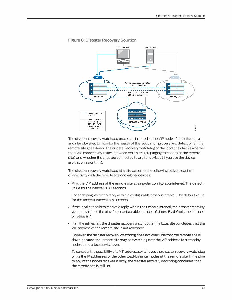
Figure 8: Disaster Recovery Solution
The disaster recovery watchdog process is initiated at the VIP node of both the active
and standby sites to monitor the health of the replication process and detect when the
remote site goes down. The disaster recovery watchdog at the local site checks whether
there are connectivity issues between both sites (by pinging the nodes at the remote
site) and whether the sites are connected to arbiter devices (if you use the device
arbitration algorithm).
The disaster recovery watchdog at a site performs the following tasks to confirm
connectivity with the remote site and arbiter devices:
• Ping the VIP address of the remote site at a regular configurable interval. The default
value for the interval is 30 seconds.
For each ping, expect a reply within a configurable timeout interval. The default value
for the timeout interval is 5 seconds.
• If the local site fails to receive a reply within the timeout interval, the disaster recovery
watchdog retries the ping for a configurable number of times. By default, the number
of retries is 4.
• If all the retries fail, the disaster recovery watchdog at the local site concludes that the
VIP address of the remote site is not reachable.
However, the disaster recovery watchdog does not conclude that the remote site is
down because the remote site may be switching over the VIP address to a standby
node due to a local switchover.
• To consider the possibility of a VIP address switchover, the disaster recovery watchdog
pings the IP addresses of the other load-balancer nodes at the remote site. If the ping
to any of the nodes receives a reply, the disaster recovery watchdog concludes that
the remote site is still up.
47Copyright © 2016, Juniper Networks, Inc.
Chapter 6: Disaster Recovery Solution
If the ping to the nodes fails, the disaster recovery watchdog does not conclude that
the remote site is down. Instead, the disaster recovery watchdog considers the possibility
of connectivity issues between the sites. Both sites will try to become active.
• To prevent both sites from trying to become active, the disaster recovery watchdog
initiates the device arbitration algorithm and determines whether a failover is required.
A failover is initiated only if the percentage of arbiter devices managed by the active
site falls below the failover threshold. Then the active site becomes the standby site
and the standby site becomes the active site.
If the percentage of arbiter devices is above the failover threshold, the standby site
remains standby and the active site remains active. The percentage of arbiter devices
managed by the active site is configurable and its default value is 50%.
The failover is initiated if the following conditions are met:
• The standby site cannot reach the VIP address of the active site or the node IP addresses
of other load-balancer nodes at the active site.
• The percentage of the arbiter devices managed by the active site is below the failover
threshold.
For more information about the device arbitration algorithm, see “Failure Detection by
Using the Device Arbitration Algorithm” on page 51.
Prerequisites to Configure Disaster Recovery
You need to ensure that your Junos Space installation meets the following prerequisites
before you configure disaster recovery:
• The Junos Space cluster at the primary or active site (which can be a single node or
multiple nodes) and the cluster at the remote or standby site (which can be a single
node or multiple nodes) must be set up in exactly the same way, with all the same
applications, device adapters, same IP family configurations, and so on.
• Both clusters should be configured with SMTP server information from the Junos Space
user interface. For more information, see Managing SMTP Servers. This configuration
enables the clusters at both the active site and the standby site to notify the
administrator by e-mail if the replications fail.
Connectivity Requirements to Configure Disaster Recovery
You need to ensure that the disaster recovery solution meets the following connectivity
requirements before you configure disaster recovery:
• Layer 3 connectivity between the Junos Space clusters at the active and standby sites.
This means:
• Every node in a cluster can successfully ping the VIP address of the other cluster
• Every node in a cluster can use SCP to transfer files between the active and standby
sites
Copyright © 2016, Juniper Networks, Inc.48
High Availability and Disaster Recovery Guide
• Database replication across the two clusters is possible through TCP ports 3306
(MySQL database replication) and 5432 (PostgreSQL database replication)
• The bandwidth and latency of the connection between the two clusters are such
that real-time database replication is successful. Although the exact bandwidth
required depends on the amount of data transferred, we recommend a minimum of
a 100-Mbps bandwidth connection with a latency of fewer than 150 milliseconds.
• Independent Layer 3 connectivity between each cluster and managed devices
• Independent Layer 3 connectivity between each cluster and GUI or NBI clients
To set up the disaster recovery process, see “Configuring the Disaster Recovery Process
Between an Active and a Standby Site” on page 73.
Disaster RecoveryWatchdog
The disaster recovery watchdog, also known as a DR watchdog, is an in-built Junos Space
mechanism to monitor the integrity of data replication (MySQL database, PgSQL
database, configuration files, and RRD files) across sites. The disaster recovery watchdog
also monitors the overall health of the disaster recovery setup, initiates a failover from
the active to the standby site when the active site fails, and enables the standby site to
resume network management services with minimal service disruption. An instance of
the disaster recovery watchdog is initiated at the VIP node on both sites when you start
the disaster recovery process.
The disaster recovery watchdog provides the following services:
• heartbeat on page 49
• mysqlMonitor on page 50
• pgsqlMonitor on page 50
• fileMonitor on page 50
• arbiterMonitor on page 50
• configMonitor on page 50
• serviceMonitor on page 51
• notification on page 51
heartbeat
The heartbeat service between the active and standby sites uses ping to check the
connectivity between the sites. Both sites send heartbeat messages to each other. The
heartbeat service performs the following tasks:
• Detect a failure at the remote site by pinging the remote site at regular intervals.
• When the remote site fails to reply, rule out the possibility of a temporary issue due to
a local failover at the remote site.
• Enable or disable automatic failover depending on the disaster recovery configuration
settings.
49Copyright © 2016, Juniper Networks, Inc.
Chapter 6: Disaster Recovery Solution
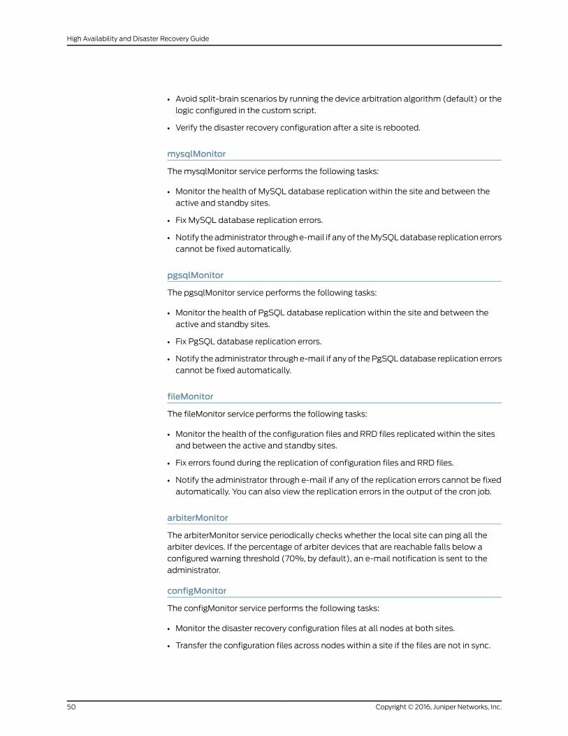
• Avoid split-brain scenarios by running the device arbitration algorithm (default) or the
logic configured in the custom script.
• Verify the disaster recovery configuration after a site is rebooted.
mysqlMonitor
The mysqlMonitor service performs the following tasks:
• Monitor the health of MySQL database replication within the site and between the
active and standby sites.
• Fix MySQL database replication errors.
• Notify the administrator through e-mail if any of the MySQL database replication errors
cannot be fixed automatically.
pgsqlMonitor
The pgsqlMonitor service performs the following tasks:
• Monitor the health of PgSQL database replication within the site and between the
active and standby sites.
• Fix PgSQL database replication errors.
• Notify the administrator through e-mail if any of the PgSQL database replication errors
cannot be fixed automatically.
fileMonitor
The fileMonitor service performs the following tasks:
• Monitor the health of the configuration files and RRD files replicated within the sites
and between the active and standby sites.
• Fix errors found during the replication of configuration files and RRD files.
• Notify the administrator through e-mail if any of the replication errors cannot be fixed
automatically. You can also view the replication errors in the output of the cron job.
arbiterMonitor
The arbiterMonitor service periodically checks whether the local site can ping all the
arbiter devices. If the percentage of arbiter devices that are reachable falls below a
configured warning threshold (70%, by default), an e-mail notification is sent to the
administrator.
configMonitor
The configMonitor service performs the following tasks:
• Monitor the disaster recovery configuration files at all nodes at both sites.
• Transfer the configuration files across nodes within a site if the files are not in sync.
Copyright © 2016, Juniper Networks, Inc.50
High Availability and Disaster Recovery Guide
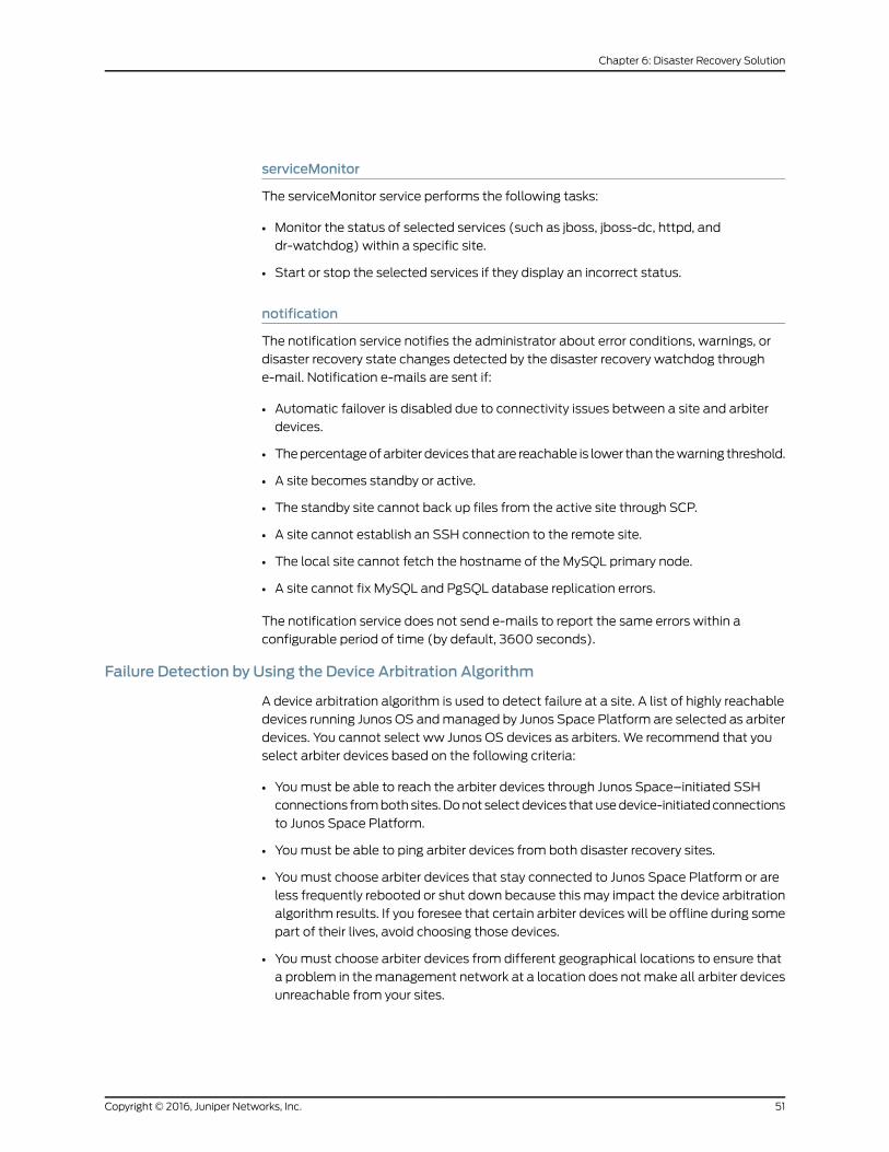
serviceMonitor
The serviceMonitor service performs the following tasks:
• Monitor the status of selected services (such as jboss, jboss-dc, httpd, and
dr-watchdog) within a specific site.
• Start or stop the selected services if they display an incorrect status.
notification
The notification service notifies the administrator about error conditions, warnings, or
disaster recovery state changes detected by the disaster recovery watchdog through
e-mail. Notification e-mails are sent if:
• Automatic failover is disabled due to connectivity issues between a site and arbiter
devices.
• The percentage of arbiter devices that are reachable is lower than the warning threshold.
• A site becomes standby or active.
• The standby site cannot back up files from the active site through SCP.
• A site cannot establish an SSH connection to the remote site.
• The local site cannot fetch the hostname of the MySQL primary node.
• A site cannot fix MySQL and PgSQL database replication errors.
The notification service does not send e-mails to report the same errors within a
configurable period of time (by default, 3600 seconds).
Failure Detection by Using the Device Arbitration Algorithm
A device arbitration algorithm is used to detect failure at a site. A list of highly reachable
devices running Junos OS and managed by Junos Space Platform are selected as arbiter
devices. You cannot select ww Junos OS devices as arbiters. We recommend that you
select arbiter devices based on the following criteria:
• You must be able to reach the arbiter devices through Junos Space–initiated SSH
connections from both sites. Do not select devices that use device-initiated connections
to Junos Space Platform.
• You must be able to ping arbiter devices from both disaster recovery sites.
• You must choose arbiter devices that stay connected to Junos Space Platform or are
less frequently rebooted or shut down because this may impact the device arbitration
algorithm results. If you foresee that certain arbiter devices will be offline during some
part of their lives, avoid choosing those devices.
• You must choose arbiter devices from different geographical locations to ensure that
a problem in the management network at a location does not make all arbiter devices
unreachable from your sites.
51Copyright © 2016, Juniper Networks, Inc.
Chapter 6: Disaster Recovery Solution

The device arbitration algorithm at the active site uses ping to connect to arbiter devices
from the active site. The device arbitration algorithm at the standby site logs in to the
arbiter devices through SSH connections by using the login credentials from the Junos
Space Platform database. Following are the workflows of the device arbitration algorithm
at the active and standby sites.
At the active site:
1. Ping all selected arbiter devices.
2. Compute the percentage of arbiter devices that can be pinged.
3. Check whether the percentage of arbiter devices that can be pinged is above or the
same as the configured value of the failover threshold.
• If the percentage of arbiter devices connected is above or the same as the configured
value of the failover threshold (failureDetection.threshold.failover parameter in the
watchdog section of the disaster recovery API), failover is not initiated because the
active site is managing a majority of the arbiter devices.
• If the percentage of arbiter devices is below the configured value of the failover
threshold, failover is initiated (if automatic failover is enabled) and the active site
becomes standby. If automatic failover is disabled, the active site remains active.
At the standby site:
1. Log in to arbiter devices through SSH connections.
2. Execute a command on each arbiter device to retrieve the list of SSH connections to
any node (managed by the node) at the active site.
3. Calculate the percentage of arbiter devices managed by the active site.
4. Calculate the percentage of arbiter devices that cannot be reached through SSH
connections.
• If the percentage of arbiter devices managed by the active site is above or the same
as the configured value of the failover threshold, failover is not required because
the active site is still managing a majority of the arbiter devices.
• If the percentage of arbiter devices managed by the active site is below the
configured value of the failover threshold, the disaster recovery watchdog concludes
that a failover may be required.
5. However, because the devices that cannot be reached from the standby site may be
connected and managed by the active site, the standby site assumes that all arbiter
devices that cannot be reached are being managed by the active site and calculates
the new percentage of devices managed by the active site.
• If the percentage of devices managed by the active site is below the threshold
percentage to adjust managed devices (failureDetection.threshold.adjustManaged
parameter in the watchdog section of the disaster recovery API, the default value
is 50%), the standby site remains standby. By default, the threshold percentage to
adjust managed devices must be below the failover threshold.
Copyright © 2016, Juniper Networks, Inc.52
High Availability and Disaster Recovery Guide
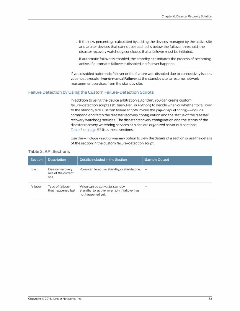
• If the new percentage calculated by adding the devices managed by the active site
and arbiter devices that cannot be reached is below the failover threshold, the
disaster recovery watchdog concludes that a failover must be initiated.
If automatic failover is enabled, the standby site initiates the process of becoming
active. If automatic failover is disabled, no failover happens.
If you disabled automatic failover or the feature was disabled due to connectivity issues,
you must execute jmp-drmanualFailover at the standby site to resume network
management services from the standby site.
Failure Detection by Using the Custom Failure-Detection Scripts
In addition to using the device arbitration algorithm, you can create custom
failure-detection scripts (sh, bash, Perl, or Python) to decide when or whether to fail over
to the standby site. Custom failure scripts invoke the jmp-dr api v1 config ––include
command and fetch the disaster recovery configuration and the status of the disaster
recovery watchdog services. The disaster recovery configuration and the status of the
disaster recovery watchdog services at a site are organized as various sections.
Table 3 on page 53 lists these sections.
Use the -- include<section-name>option to view the details of a section or use the details
of the section in the custom failure-detection script.
Table 3: API Sections
Sample OutputDetails Included in the SectionDescriptionSection
–Roles can be active, standby, or standalone.Disaster recoveryrole of the currentsite
role
–Value can be active_to_standby,standby_to_active, or empty if failover hasnot happened yet.
Type of failoverthat happened last
failover
53Copyright © 2016, Juniper Networks, Inc.
Chapter 6: Disaster Recovery Solution
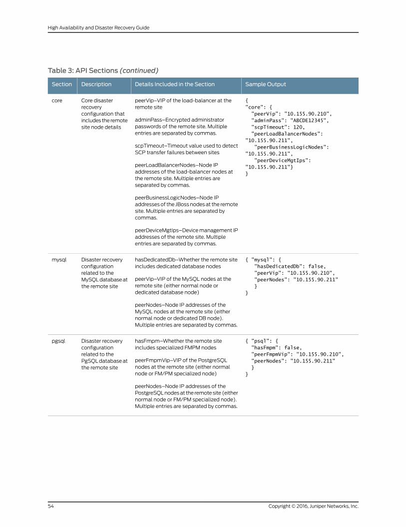
Table 3: API Sections (continued)
Sample OutputDetails Included in the SectionDescriptionSection
{ "core": { "peerVip": "10.155.90.210", "adminPass": "ABCDE12345", "scpTimeout": 120, "peerLoadBalancerNodes": "10.155.90.211", "peerBusinessLogicNodes": "10.155.90.211", "peerDeviceMgtIps": "10.155.90.211"}}
peerVip–VIP of the load-balancer at theremote site
adminPass–Encrypted administratorpasswords of the remote site. Multipleentries are separated by commas.
scpTimeout–Timeout value used to detectSCP transfer failures between sites
peerLoadBalancerNodes–Node IPaddresses of the load-balancer nodes atthe remote site. Multiple entries areseparated by commas.
peerBusinessLogicNodes–Node IPaddresses of the JBoss nodes at the remotesite. Multiple entries are separated bycommas.
peerDeviceMgtIps–Device management IPaddresses of the remote site. Multipleentries are separated by commas.
Core disasterrecoveryconfiguration thatincludes the remotesite node details
core
{ "mysql": { "hasDedicatedDb": false, "peerVip": "10.155.90.210", "peerNodes": "10.155.90.211" }}
hasDedicatedDb–Whether the remote siteincludes dedicated database nodes
peerVip–VIP of the MySQL nodes at theremote site (either normal node ordedicated database node)
peerNodes–Node IP addresses of theMySQL nodes at the remote site (eithernormal node or dedicated DB node).Multiple entries are separated by commas.
Disaster recoveryconfigurationrelated to theMySQL database atthe remote site
mysql
{ "psql": { "hasFmpm": false, "peerFmpmVip": "10.155.90.210", "peerNodes": "10.155.90.211" }}
hasFmpm–Whether the remote siteincludes specialized FMPM nodes
peerFmpmVip–VIP of the PostgreSQLnodes at the remote site (either normalnode or FM/PM specialized node)
peerNodes–Node IP addresses of thePostgreSQL nodes at the remote site (eithernormal node or FM/PM specialized node).Multiple entries are separated by commas.
Disaster recoveryconfigurationrelated to thePgSQL database atthe remote site
pgsql
Copyright © 2016, Juniper Networks, Inc.54
High Availability and Disaster Recovery Guide
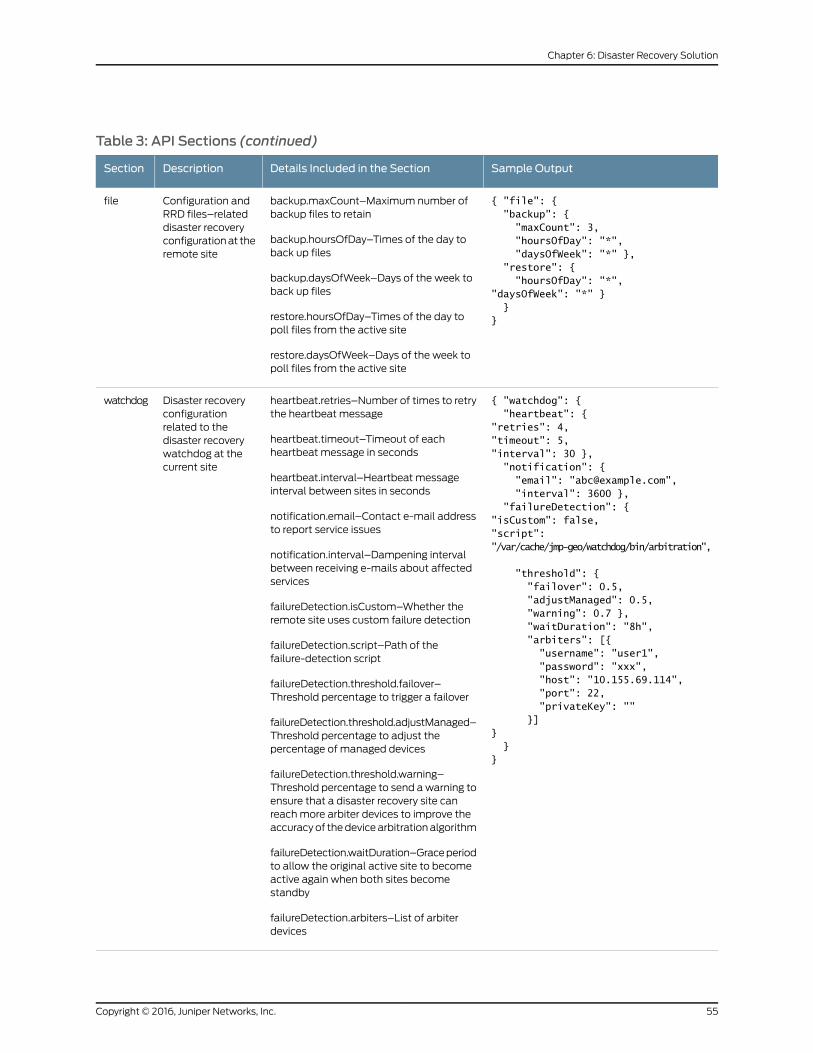
Table 3: API Sections (continued)
Sample OutputDetails Included in the SectionDescriptionSection
{ "file": { "backup": { "maxCount": 3, "hoursOfDay": "*", "daysOfWeek": "*" }, "restore": { "hoursOfDay": "*","daysOfWeek": "*" } }}
backup.maxCount–Maximum number ofbackup files to retain
backup.hoursOfDay–Times of the day toback up files
backup.daysOfWeek–Days of the week toback up files
restore.hoursOfDay–Times of the day topoll files from the active site
restore.daysOfWeek–Days of the week topoll files from the active site
Configuration andRRD files–relateddisaster recoveryconfiguration at theremote site
file
{ "watchdog": { "heartbeat": {"retries": 4,"timeout": 5,"interval": 30 }, "notification": { "email": "[email protected]", "interval": 3600 }, "failureDetection": {"isCustom": false,"script": "/var/cache/jmp-geo/watchdog/bin/arbitration",
"threshold": { "failover": 0.5, "adjustManaged": 0.5, "warning": 0.7 }, "waitDuration": "8h", "arbiters": [{ "username": "user1", "password": "xxx", "host": "10.155.69.114", "port": 22, "privateKey": "" }]} }}
heartbeat.retries–Number of times to retrythe heartbeat message
heartbeat.timeout–Timeout of eachheartbeat message in seconds
heartbeat.interval–Heartbeat messageinterval between sites in seconds
notification.email–Contact e-mail addressto report service issues
notification.interval–Dampening intervalbetween receiving e-mails about affectedservices
failureDetection.isCustom–Whether theremote site uses custom failure detection
failureDetection.script–Path of thefailure-detection script
failureDetection.threshold.failover–Threshold percentage to trigger a failover
failureDetection.threshold.adjustManaged–Threshold percentage to adjust thepercentage of managed devices
failureDetection.threshold.warning–Threshold percentage to send a warning toensure that a disaster recovery site canreach more arbiter devices to improve theaccuracy of the device arbitration algorithm
failureDetection.waitDuration–Grace periodto allow the original active site to becomeactive again when both sites becomestandby
failureDetection.arbiters–List of arbiterdevices
Disaster recoveryconfigurationrelated to thedisaster recoverywatchdog at thecurrent site
watchdog
55Copyright © 2016, Juniper Networks, Inc.
Chapter 6: Disaster Recovery Solution
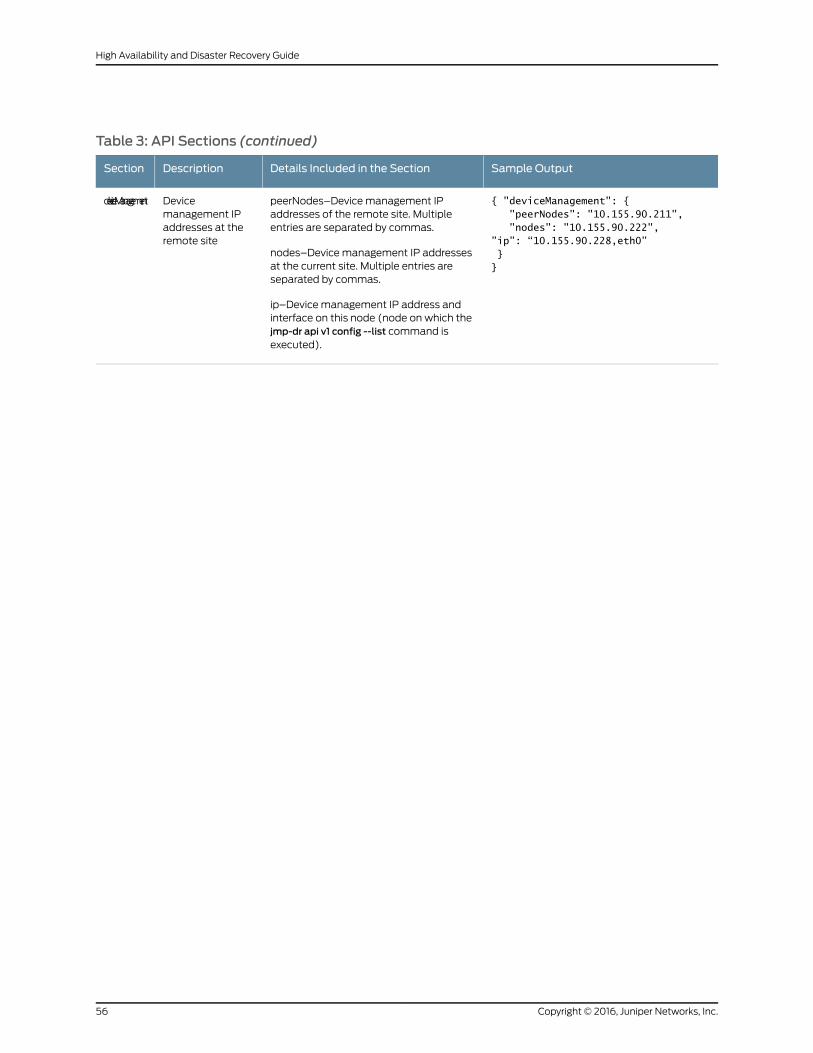
Table 3: API Sections (continued)
Sample OutputDetails Included in the SectionDescriptionSection
{ "deviceManagement": { "peerNodes": "10.155.90.211", "nodes": "10.155.90.222",”ip”: “10.155.90.228,eth0” }}
peerNodes–Device management IPaddresses of the remote site. Multipleentries are separated by commas.
nodes–Device management IP addressesat the current site. Multiple entries areseparated by commas.
ip–Device management IP address andinterface on this node (node on which thejmp-dr api v1 config --list command isexecuted).
Devicemanagement IPaddresses at theremote site
deviceManagement
Copyright © 2016, Juniper Networks, Inc.56
High Availability and Disaster Recovery Guide
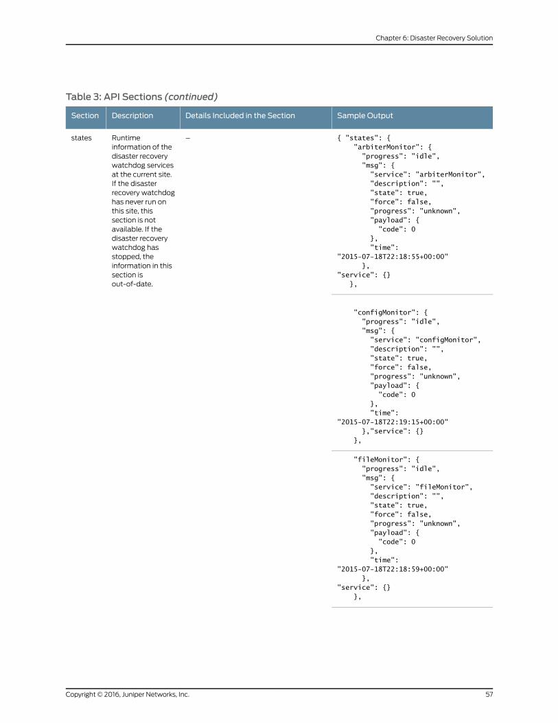
Table 3: API Sections (continued)
Sample OutputDetails Included in the SectionDescriptionSection
{ "states": { "arbiterMonitor": { "progress": "idle", "msg": { "service": "arbiterMonitor", "description": "", "state": true, "force": false, "progress": "unknown", "payload": { "code": 0 }, "time": "2015-07-18T22:18:55+00:00" },"service": {} },
–Runtimeinformation of thedisaster recoverywatchdog servicesat the current site.If the disasterrecovery watchdoghas never run onthis site, thissection is notavailable. If thedisaster recoverywatchdog hasstopped, theinformation in thissection isout-of-date.
states
"configMonitor": { "progress": "idle", "msg": { "service": "configMonitor", "description": "", "state": true, "force": false, "progress": "unknown", "payload": { "code": 0 }, "time": "2015-07-18T22:19:15+00:00" },"service": {} },
"fileMonitor": { "progress": "idle", "msg": { "service": "fileMonitor", "description": "", "state": true, "force": false, "progress": "unknown", "payload": { "code": 0 }, "time": "2015-07-18T22:18:59+00:00" },"service": {} },
57Copyright © 2016, Juniper Networks, Inc.
Chapter 6: Disaster Recovery Solution
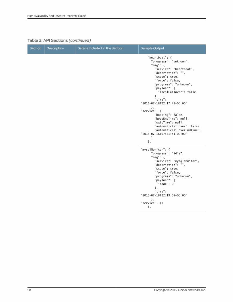
Table 3: API Sections (continued)
Sample OutputDetails Included in the SectionDescriptionSection
"heartbeat": { "progress": "unknown", "msg": { "service": "heartbeat", "description": "", "state": true, "force": false, "progress": "unknown", "payload": { "localFailover": false }, "time": "2015-07-18T22:17:49+00:00" },"service": { "booting": false, "bootEndTime": null, "waitTime": null, "automaticFailover": false, "automaticFailoverEndTime": "2015-07-18T07:41:41+00:00" } },
"mysqlMonitor": { "progress": "idle", "msg": { "service": "mysqlMonitor", "description": "", "state": true, "force": false, "progress": "unknown", "payload": { "code": 0 }, "time": "2015-07-18T22:19:09+00:00" },"service": {} },
Copyright © 2016, Juniper Networks, Inc.58
High Availability and Disaster Recovery Guide
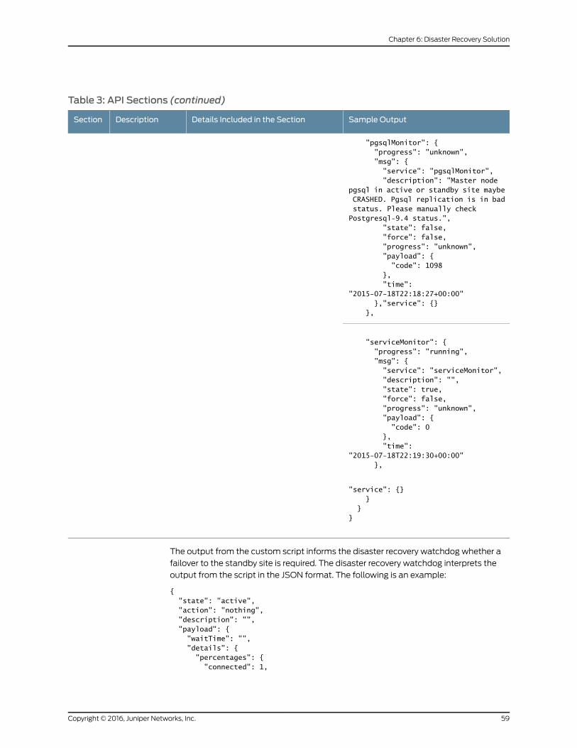
Table 3: API Sections (continued)
Sample OutputDetails Included in the SectionDescriptionSection
"pgsqlMonitor": { "progress": "unknown", "msg": { "service": "pgsqlMonitor", "description": "Master node pgsql in active or standby site maybe CRASHED. Pgsql replication is in bad status. Please manually check Postgresql-9.4 status.", "state": false, "force": false, "progress": "unknown", "payload": { "code": 1098 }, "time": "2015-07-18T22:18:27+00:00" },"service": {} },
"serviceMonitor": { "progress": "running", "msg": { "service": "serviceMonitor", "description": "", "state": true, "force": false, "progress": "unknown", "payload": { "code": 0 }, "time": "2015-07-18T22:19:30+00:00" },
"service": {} } }}
The output from the custom script informs the disaster recovery watchdog whether a
failover to the standby site is required. The disaster recovery watchdog interprets the
output from the script in the JSON format. The following is an example:
{ "state": "active", "action": "nothing", "description": "", "payload": { "waitTime": "", "details": { "percentages": { "connected": 1,
59Copyright © 2016, Juniper Networks, Inc.
Chapter 6: Disaster Recovery Solution
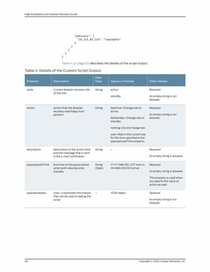
"arbiters": { "10.155.69.114": "reachable" } } } }}
Table 4 on page 60 describes the details of the script output.
Table 4: Details of the CustomScript Output
Other DetailsValues or FormatDataTypeDescriptionProperty
Required
An empty string is notallowed.
active
standby
StringCurrent disaster recovery roleof this site
state
Required
An empty string is notallowed.
beActive–Change role toactive.
beStandby–Change role tostandby.
nothing–Do not change role.
wait–Wait in the current rolefor the time specified in thepayload.waitTime property.
StringAction that the disasterrecovery watchdog mustperform
action
Required
An empty string is allowed.
–StringDescription of the action fieldand the message that is sentin the e-mail notification
description
Required
An empty string is allowed.
This property is used whenyou specify the value ofaction as wait.
YYYY-MM-DD, UTC time inHH:MM+00:00 format
String(Date)
End time of the grace periodwhen both sites becomestandby
payload.waitTime
Optional
An empty string is notallowed.
JSON object–User- customized informationthat can be used to debug thescript
payload.details
Copyright © 2016, Juniper Networks, Inc.60
High Availability and Disaster Recovery Guide
Steps to Configure Disaster Recovery
To configure disaster recovery between an active site and a standby site:
1. Stop the disaster recovery process configured during earlier releases before upgrading
to Junos Space Network Management Platform Release 15.1R1. For more information,
see “Stopping the Disaster Recovery Process on Junos Space Network Management
Platform Release 14.1R3 and Earlier” on page 82.
You do not require to perform this step for a clean installation of Junos Space Network
Management Platform Release 15.1R1.
2. Set up SMTP servers at both sites from the Junos Space user interface to receive
notifications. For more information, see Managing SMTP Servers in the Junos Space
Network Management PlatformWorkspaces Feature Guide.
3. Copy the file with the list of arbiter devices (if you are using the device arbitration
algorithm) or the custom failure-detection script to the appropriate location at the
active site. Ensure that all arbiter devices are discovered at the active site. For more
information, seeDiscoveringDevices in the JunosSpaceNetworkManagementPlatform
Workspaces Feature Guide.
4. Configure the disaster recovery configuration file at the active site. The disaster recovery
configuration includes SCP settings to synchronize configuration and RRD files,
heartbeat settings, notifications settings, and the failure-detection mechanism.
5. Configure the disaster recovery configuration file at the standby site. The disaster
recovery configuration includes SCP settings to synchronize configuration and RRD
files, heartbeat settings, and notification settings.
6. Start the disaster recovery process from the active site.
For more information, see “Configuring the Disaster Recovery Process Between an
Active and a Standby Site” on page 73.
Disaster Recovery Commands
You use the disaster recovery commands listed in Table 5 on page 62 to configure and
manage disaster recovery sites. You must execute these commands at the VIP node of
the site. You can use the --help option with these commands to view more information.
61Copyright © 2016, Juniper Networks, Inc.
Chapter 6: Disaster Recovery Solution
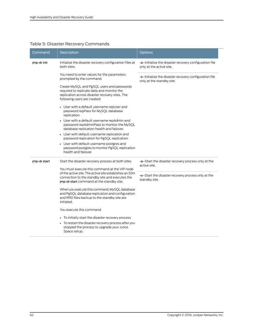
Table 5: Disaster Recovery Commands
OptionsDescriptionCommand
-a–Initialize the disaster recovery configuration fileonly at the active site.
Initialize the disaster recovery configuration files atboth sites.
You need to enter values for the parametersprompted by the command.
Create MySQL and PgSQL users and passwordsrequired to replicate data and monitor thereplication across disaster recovery sites. Thefollowing users are created:
• User with a default username repUser andpassword repPass for MySQL databasereplication.
• User with a default username repAdmin andpassword repAdminPass to monitor the MySQLdatabase replication health and failover.
• User with default username replication andpassword replication for PgSQL replication.
• User with default username postgres andpassword postgres to monitor PgSQL replicationhealth and failover.
jmp-dr init
-s–Initialize the disaster recovery configuration fileonly at the standby site.
-a–Start the disaster recovery process only at theactive site.
Start the disaster recovery process at both sites.
You must execute this command at the VIP nodeof the active site. The active site establishes an SSHconnection to the standby site and executes thejmp-dr start command at the standby site.
When you execute this command, MySQL databaseand PgSQL database replication and configurationand RRD files backup to the standby site areinitiated.
You execute this command:
• To initially start the disaster recovery process
• To restart the disaster recovery process after youstopped the process to upgrade your JunosSpace setup.
jmp-dr start
-s–Start the disaster recovery process only at thestandby site.
Copyright © 2016, Juniper Networks, Inc.62
High Availability and Disaster Recovery Guide
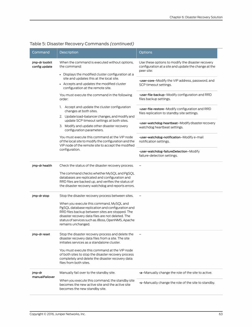
Table 5: Disaster Recovery Commands (continued)
OptionsDescriptionCommand
Use these options to modify the disaster recoveryconfiguration at a site and update the change at thepeer site:
When the command is executed without options,the command:
• Displays the modified cluster configuration at asite and updates this at the local site.
• Accepts and updates the modified clusterconfiguration at the remote site.
You must execute the command in the followingorder:
1. Accept and update the cluster configurationchanges at both sites.
2. Update load-balancer changes, and modify andupdate SCP timeout settings at both sites.
3. Modify and update other disaster recoveryconfiguration parameters.
You must execute this command at the VIP nodeof the local site to modify the configuration and theVIP node of the remote site to accept the modifiedconfiguration.
jmp-dr toolkitconfig update
-user-core–Modify the VIP address, password, andSCP timeout settings.
-user-file-backup–Modify configuration and RRDfiles backup settings.
-user-file-restore–Modify configuration and RRDfiles replication to standby site settings.
-user-watchdog-heartbeat–Modify disaster recoverywatchdog heartbeat settings.
-user-watchdog-notification–Modify e-mailnotification settings.
-user-watchdog-failureDetection–Modifyfailure-detection settings.
–Check the status of the disaster recovery process.
The command checks whether MySQL and PgSQLdatabases are replicated and configuration andRRD files are backed up, and verifies the status ofthe disaster recovery watchdog and reports errors.
jmp-dr health
–Stop the disaster recovery process between sites.
When you execute this command, MySQL andPgSQL database replication and configuration andRRD files backup between sites are stopped. Thedisaster recovery data files are not deleted. Thestatus of services such as JBoss, OpenNMS, Apacheremains unchanged.
jmp-dr stop
–Stop the disaster recovery process and delete thedisaster recovery data files from a site. The siteinitiates services as a standalone cluster.
You must execute this command at the VIP nodeof both sites to stop the disaster recovery processcompletely and delete the disaster recovery datafiles from both sites.
jmp-dr reset
-a–Manually change the role of the site to active.Manually fail over to the standby site.
When you execute this command, the standby sitebecomes the new active site and the active sitebecomes the new standby site.
jmp-drmanualFailover
-s–Manually change the role of the site to standby.
63Copyright © 2016, Juniper Networks, Inc.
Chapter 6: Disaster Recovery Solution
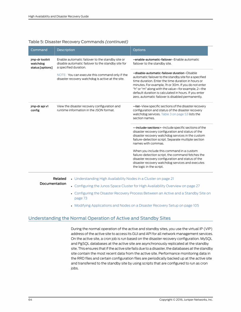
Table 5: Disaster Recovery Commands (continued)
OptionsDescriptionCommand
–enable-automatic-failover–Enable automaticfailover to the standby site.
Enable automatic failover to the standby site ordisable automatic failover to the standby site fora specified duration.
NOTE: You can execute this command only if thedisaster recovery watchdog is active at the site.
jmp-dr toolkitwatchdogstatus[options]
–disable-automatic-failover duration–Disableautomatic failover to the standby site for a specifiedtime duration. Enter the time duration in hours orminutes. For example, 1h or 30m. If you do not enter“h” or “m” along with the value—for example, 2—thedefault duration is calculated in hours. If you enterzero, automatic failover is disabled permanently.
--list–View specific sections of the disaster recoveryconfiguration and status of the disaster recoverywatchdog services. Table 3 on page 53 lists thesection names.
View the disaster recovery configuration andruntime information in the JSON format.
jmp-dr api v1config
–-include<sections>–Include specific sections of thedisaster recovery configuration and status of thedisaster recovery watchdog services in the customfailure-detection script. Separate multiple sectionnames with commas.
When you include this command in a customfailure-detection script, the command fetches thedisaster recovery configuration and status of thedisaster recovery watchdog services and executesthe logic in the script.
RelatedDocumentation
Understanding High Availability Nodes in a Cluster on page 21•
• Configuring the Junos Space Cluster for High Availability Overview on page 27
• Configuring the Disaster Recovery Process Between an Active and a Standby Site on
page 73
• Modifying Applications and Nodes on a Disaster Recovery Setup on page 105
Understanding the Normal Operation of Active and Standby Sites
During the normal operation of the active and standby sites, you use the virtual IP (VIP)
address of the active site to access its GUI and API for all network management services.
On the active site, a cron job is run based on the disaster recovery configuration. MySQL
and PgSQL databases at the active site are asynchronously replicated at the standby
site. This ensures that if the active site fails due to a disaster, the databases at the standby
site contain the most recent data from the active site. Performance monitoring data in
the RRD files and certain configuration files are periodically backed up at the active site
and transferred to the standby site by using scripts that are configured to run as cron
jobs.
Copyright © 2016, Juniper Networks, Inc.64
High Availability and Disaster Recovery Guide
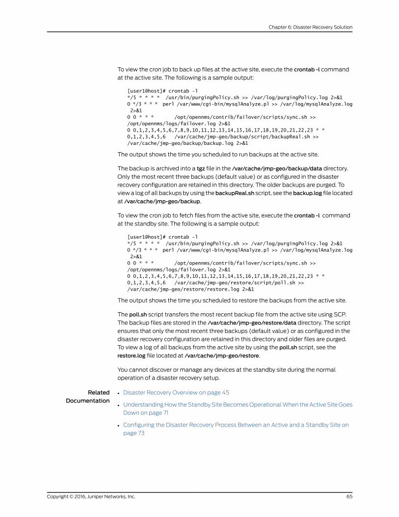
To view the cron job to back up files at the active site, execute the crontab -l command
at the active site. The following is a sample output:
[user1@host]# crontab -l*/5 * * * * /usr/bin/purgingPolicy.sh >> /var/log/purgingPolicy.log 2>&10 */3 * * * perl /var/www/cgi-bin/mysqlAnalyze.pl >> /var/log/mysqlAnalyze.log 2>&10 0 * * * /opt/opennms/contrib/failover/scripts/sync.sh >> /opt/opennms/logs/failover.log 2>&10 0,1,2,3,4,5,6,7,8,9,10,11,12,13,14,15,16,17,18,19,20,21,22,23 * * 0,1,2,3,4,5,6 /var/cache/jmp-geo/backup/script/backupReal.sh >> /var/cache/jmp-geo/backup/backup.log 2>&1
The output shows the time you scheduled to run backups at the active site.
The backup is archived into a tgz file in the /var/cache/jmp-geo/backup/data directory.
Only the most recent three backups (default value) or as configured in the disaster
recovery configuration are retained in this directory. The older backups are purged. To
view a log of all backups by using thebackupReal.sh script, see thebackup.log file located
at /var/cache/jmp-geo/backup.
To view the cron job to fetch files from the active site, execute the crontab -l command
at the standby site. The following is a sample output:
[user1@host]# crontab -l*/5 * * * * /usr/bin/purgingPolicy.sh >> /var/log/purgingPolicy.log 2>&10 */3 * * * perl /var/www/cgi-bin/mysqlAnalyze.pl >> /var/log/mysqlAnalyze.log 2>&10 0 * * * /opt/opennms/contrib/failover/scripts/sync.sh >> /opt/opennms/logs/failover.log 2>&10 0,1,2,3,4,5,6,7,8,9,10,11,12,13,14,15,16,17,18,19,20,21,22,23 * * 0,1,2,3,4,5,6 /var/cache/jmp-geo/restore/script/poll.sh >> /var/cache/jmp-geo/restore/restore.log 2>&1
The output shows the time you scheduled to restore the backups from the active site.
The poll.sh script transfers the most recent backup file from the active site using SCP.
The backup files are stored in the /var/cache/jmp-geo/restore/data directory. The script
ensures that only the most recent three backups (default value) or as configured in the
disaster recovery configuration are retained in this directory and older files are purged.
To view a log of all backups from the active site by using the poll.sh script, see the
restore.log file located at /var/cache/jmp-geo/restore.
You cannot discover or manage any devices at the standby site during the normal
operation of a disaster recovery setup.
RelatedDocumentation
Disaster Recovery Overview on page 45•
• Understanding How the Standby Site Becomes Operational When the Active Site Goes
Down on page 71
• Configuring the Disaster Recovery Process Between an Active and a Standby Site on
page 73
65Copyright © 2016, Juniper Networks, Inc.
Chapter 6: Disaster Recovery Solution
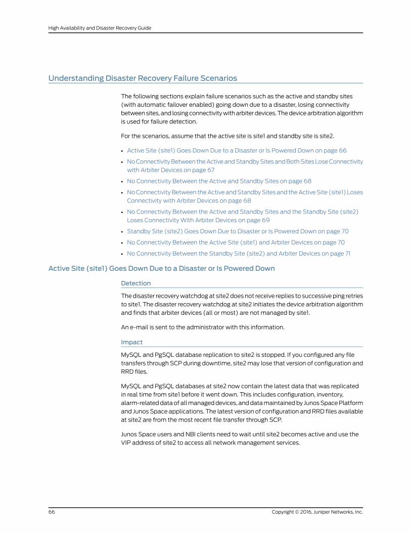
Understanding Disaster Recovery Failure Scenarios
The following sections explain failure scenarios such as the active and standby sites
(with automatic failover enabled) going down due to a disaster, losing connectivity
between sites, and losing connectivity with arbiter devices. The device arbitration algorithm
is used for failure detection.
For the scenarios, assume that the active site is site1 and standby site is site2.
• Active Site (site1) Goes Down Due to a Disaster or Is Powered Down on page 66
• No Connectivity Between the Active and Standby Sites and Both Sites Lose Connectivity
with Arbiter Devices on page 67
• No Connectivity Between the Active and Standby Sites on page 68
• No Connectivity Between the Active and Standby Sites and the Active Site (site1) Loses
Connectivity with Arbiter Devices on page 68
• No Connectivity Between the Active and Standby Sites and the Standby Site (site2)
Loses Connectivity With Arbiter Devices on page 69
• Standby Site (site2) Goes Down Due to Disaster or Is Powered Down on page 70
• No Connectivity Between the Active Site (site1) and Arbiter Devices on page 70
• No Connectivity Between the Standby Site (site2) and Arbiter Devices on page 71
Active Site (site1) Goes Down Due to a Disaster or Is Powered Down
Detection
The disaster recovery watchdog at site2 does not receive replies to successive ping retries
to site1. The disaster recovery watchdog at site2 initiates the device arbitration algorithm
and finds that arbiter devices (all or most) are not managed by site1.
An e-mail is sent to the administrator with this information.
Impact
MySQL and PgSQL database replication to site2 is stopped. If you configured any file
transfers through SCP during downtime, site2 may lose that version of configuration and
RRD files.
MySQL and PgSQL databases at site2 now contain the latest data that was replicated
in real time from site1 before it went down. This includes configuration, inventory,
alarm-related data of all managed devices, and data maintained by Junos Space Platform
and Junos Space applications. The latest version of configuration and RRD files available
at site2 are from the most recent file transfer through SCP.
Junos Space users and NBI clients need to wait until site2 becomes active and use the
VIP address of site2 to access all network management services.
Copyright © 2016, Juniper Networks, Inc.66
High Availability and Disaster Recovery Guide
Recovery
The disaster recovery watchdog at site2 initiates the process to become active. The
complete process may take around 15 to 20 minutes. This can vary depending on the
number of devices that are managed on your Junos Space setup.
When the failover is complete, site2 establishes connections with all devices and
resynchronizes configuration and inventory data if required. site2 starts receiving alarms
and performance management data from managed devices.
NOTE: When you rebuild or power on site1, if the disaster recoveryconfiguration is deleted, youmust reconfigure disaster recovery between thesites.
No Connectivity Between the Active and Standby Sites and Both Sites Lose Connectivity withArbiter Devices
Detection
The disaster recovery watchdog at both sites do not receive replies to successive ping
retries. The disaster recovery watchdog at both sites initiates the device arbitration
algorithm.
An e-mail is sent to the administrator regarding the failure of MySQL and PgSQL
replication and file transfer through SCP between sites.
Impact
MySQL and PgSQL database replication to site2 is stopped. If you configured any file
transfers through SCP during downtime, site2 may lose that version of configuration and
RRD files.
Because both sites cannot connect to arbiter devices (all or most), both sites cannot
determine the status of the other site. site1 starts to become standby and site2 remains
standby to avoid a split-brain situation.
Even if connectivity between the two sites is restored, both sites remain standby because
the sites cannot connect to arbiter devices.
The network management services are stopped at both sites until one of the sites
becomes active.
If connectivity to arbiter devices is not restored within the grace period (by default, eight
hours), automatic failover functionality is disabled at both sites. An e-mail is sent every
hour to the administrator with this information.
Recovery
If connectivity to arbiter devices is restored within the grace period (by default, eight
hours), site1 becomes active again. site2 remains standby.
67Copyright © 2016, Juniper Networks, Inc.
Chapter 6: Disaster Recovery Solution
If both sites are standby, enable disaster recovery by executing the jmp-drmanualFailover
–a command at the VIP node of site1. To enable automatic failover at the sites, execute
the jmp-dr toolkitwatchdogstatus--enable-automatic-failovercommand at the VIP node
of site1 and site2.
Fix connectivity issues between site1 and site2 to resume MySQL and PgSQL replication
and file transfer through SCP.
No Connectivity Between the Active and Standby Sites
Detection
The disaster recovery watchdog at both sites do not receive replies to successive ping
retries. The disaster recovery watchdog at both sites initiates the device arbitration
algorithm and finds that arbiter devices (all or most) are managed by site1.
An e-mail is sent to the administrator regarding the failure of MySQL and PgSQL database
replication and file transfer through SCP between sites.
Impact
MySQL and PgSQL database replication to site2 is stopped. If you configured any file
transfers through SCP during downtime, site2 may lose that version of configuration and
RRD files.
Recovery
site1 remains active and site2 remains standby. Fix connectivity issues between site1 and
site2 to resume MySQL and PgSQL database replication and file transfer through SCP.
No Connectivity Between the Active and Standby Sites and the Active Site (site1) LosesConnectivity with Arbiter Devices
Detection
The disaster recovery watchdog at both sites do not receive replies to successive ping
retries. The disaster recovery watchdog at both sites initiates the device arbitration
algorithm.
An e-mail is sent to the administrator regarding the failure of MySQL and PgSQL database
replication and file transfer through SCP between sites.
Impact
MySQL and PgSQL database replication to site2 is stopped. If you configured any file
transfers through SCP during downtime, site2 may lose that version of configuration and
RRD files.
Because site1 cannot connect to arbiter devices, site1 starts to become standby. Because
site2 finds that arbiter devices (all or most) are not managed by site1, a failover is initiated.
As part of becoming standby, all network management services are stopped at site1.
Copyright © 2016, Juniper Networks, Inc.68
High Availability and Disaster Recovery Guide
site2 now contains the latest MySQL and PgSQL data that was replicated in real time
from site1. The latest version of configuration and RRD files available at site2 are from
the most recent file transfer through SCP.
Junos Space users and NBI clients need to wait until site2 becomes active and use the
VIP address of site2 to access all network management services.
Recovery
The disaster recovery watchdog at site2 initiates the process to become active. The
complete process may take around 15 to 20 minutes. This can vary depending on the
number of devices that are managed on your Junos Space setup.
When the failover is complete, site2 establishes connections with all devices and
resynchronizes configuration and inventory data if required. site2 starts receiving alarms
and performance management data from managed devices.
Fix connectivity issues between site1 and site2 to resume MySQL and PgSQL database
replication and file transfer through SCP.
No Connectivity Between the Active and Standby Sites and the Standby Site (site2) LosesConnectivityWith Arbiter Devices
Detection
The disaster recovery watchdog at both sites do not receive replies to successive ping
retries. The disaster recovery watchdog at site1 initiates the device arbitration algorithm
and finds that arbiter devices (all or most) are managed by site1. The disaster recovery
watchdog at site2 initiates the device arbitration algorithm.
An e-mail is sent to the administrator regarding the failure of MySQL and PgSQL
replication and file transfer through SCP between sites.
Impact
MySQL and PgSQL database replication to site2 is stopped. If you configured any file
transfers through SCP during downtime, site2 may lose that version of configuration and
RRD files.
Because site2 cannot connect to arbiter devices (all or most), site2 remains standby.
site2 retries to connect to arbiter devices, but does not become active again even if it can
connect to enough arbiter devices within eight hours. During these eight hours, site2
requests disaster recovery runtime information of the remote site to ensure that the
remote site is active and not in the process of a failover. If site2 cannot connect to enough
arbiter devices within eight hours, site2 disables automatic failover permanently until
you manually enable automatic failover. An e-mail is sent every hour to the administrator
with this information.
Recovery
Fix connectivity issues between site1 and site2 to resume MySQL and PgSQL database
replication and file transfer through SCP.
69Copyright © 2016, Juniper Networks, Inc.
Chapter 6: Disaster Recovery Solution

To enable automatic failover at the standby site, execute the jmp-dr toolkit watchdog
status --enable-automatic-failover command at the VIP node of site2.
Standby Site (site2) Goes Down Due to Disaster or Is Powered Down
Detection
The disaster recovery watchdog at site1 does not receive replies to successive ping retries
to site2. The disaster recovery watchdog at site1 initiates the device arbitration algorithm
and finds that arbiter devices (all or most) are managed by site1.
An e-mail is sent to the administrator regarding the failure of MySQL and PgSQL
replication and file transfer through SCP between sites.
Impact
MySQL and PgSQL database replication to site2 is stopped. If you configured any file
transfers through SCP during downtime, site2 may lose that version of configuration and
RRD files.
Recovery
site1 remains active. When you power on site2, site2 becomes standby. If you powered
down or if the disaster recovery configuration is not deleted from site2, MySQL and PgSQL
database replication and file transfer through SCP are initiated.
NOTE: When you rebuild or power on site2, if the disaster recoveryconfiguration is deleted, youmust reconfigure disaster recovery betweenboth sites.
No Connectivity Between the Active Site (site1) and Arbiter Devices
Detection
The arbiterMonitor service of the disaster recovery watchdog at site1 detects that the
percentage of reachable arbiter devices is below the configured warning threshold. An
e-mail is sent to the administrator with this information.
Impact
There is no impact on the disaster recovery solution until the percentage of reachable
arbiter devices goes below the failover threshold.
Recovery
No recovery is required because network management services are available from site1.
Copyright © 2016, Juniper Networks, Inc.70
High Availability and Disaster Recovery Guide
No Connectivity Between the Standby Site (site2) and Arbiter Devices
Detection
The arbiterMonitor service of the disaster recovery watchdog at site2 detects that the
percentage of reachable arbiter devices is below the configured warning threshold. An
e-mail is sent to the administrator with this information.
Impact
There is no impact on the disaster recovery solution.
Recovery
No recovery is required because network management services are available from site1.
RelatedDocumentation
Disaster Recovery Overview on page 45•
• Modifying Applications and Nodes on a Disaster Recovery Setup on page 105
• Manually Failing Over the Network Management Services to the Standby Site on
page 116
• Understanding High Availability Failover Scenarios on page 33
UnderstandingHowtheStandbySiteBecomesOperationalWhentheActiveSiteGoesDown
When a disaster causes the active site to go down, if automatic failover is enabled and
the standby site can exceed the failure threshold, the standby site becomes operational.
Otherwise, you may need to execute the jmp-drmanualFailover or jmp-drmanualFailover
–a command at the standby site to resume network management services.
The disaster recovery watchdog at the standby site performs the following failover
operations to become an active site:
• Verify that the VIP address at the active site is not reachable.
• Stop database replication and SCP file transfer between the two sites.
• Remove the cron job from the standby site for fetching backup files from the active
site.
• Add a cron job at the standby site to back up configuration and RRD files.
• Modify the role of the standby site to active.
• Open port 7804 on all nodes at the standby site.
• Start all services at the standby site.
• Copy system configuration files contained in the backup to appropriate locations.
• Configure all devices to send SNMP traps to the VIP address of the standby site. If eth3
is used for device management at the standby site, the eth3 IP address of the active VIP
node at the standby site is configured as the trap destination, instead of the VIP address.
71Copyright © 2016, Juniper Networks, Inc.
Chapter 6: Disaster Recovery Solution
If you are monitoring devices through a dedicated FMPM node, the VIP address of the
dedicated node is configured as the trap destination.
After the failover is complete, the disaster recovery role of the site is set to Active and
the state of the cluster is set to active (1). You can access the GUI and API of the standby
site from its VIP to perform all network management tasks. In most cases, the failover
should happen within 20 to 30 minutes. When the active site becomes operational again,
it becomes the standby site. You can either retain the failed state or choose to revert to
the original state.
RelatedDocumentation
• Disaster Recovery Overview on page 45
• Understanding the Normal Operation of Active and Standby Sites on page 64
• Configuring the Disaster Recovery Process Between an Active and a Standby Site on
page 73
• Understanding High Availability Failover Scenarios on page 33
Copyright © 2016, Juniper Networks, Inc.72
High Availability and Disaster Recovery Guide
CHAPTER 7
Configuring theDisaster RecoveryProcess
• Configuring the Disaster Recovery Process Between an Active and a Standby
Site on page 73
• Stopping the Disaster Recovery Process on Junos Space Network Management Platform
Release 14.1R3 and Earlier on page 82
Configuring the Disaster Recovery Process Between an Active and a Standby Site
You configure disaster recovery between an active site and a standby site to ensure
geographical redundancy of network management services.
Before you initiate the disaster recovery process between both sites, perform the following
tasks:
• Ensure that the connectivity requirements as described in the “Disaster Recovery
Overview” on page 45 topic are met.
• Check whether identical cluster configurations exist on both sites. We recommend
that both clusters have the same number of nodes so that, even in the case of a disaster,
the standby site can operate with the same capacity as the active site.
• Ensure that the same versions of Junos Space Network Management Platform,
high-level Junos Space applications, and device adapters are installed at both sites.
• Shut down the disaster recovery process configured on Junos Space Network
Management Platform Release 14.1R3 and earlier before upgrading to Junos Space
Network Management Platform Release 15.1R1 and configuring the new disaster recovery
process. For more information, see “Stopping the Disaster Recovery Process on Junos
Space Network Management Platform Release 14.1R3 and Earlier” on page 82.
You cannot configure the new disaster recovery process if you do not stop the disaster
recovery you set up on earlier releases. You do not need to perform this step on a clean
installation of Junos Space Network Management Platform Release 15.1R1.
• Ensure that the same SMTP server configuration exists on both sites to receive e-mail
alerts related to the disaster recovery process. You can add SMTP servers from the
SMTP Servers task group in the Administration workspace. For more information about
adding SMTP servers, see Adding an SMTP Server in the Junos Space Network
Management PlatformWorkspaces Feature Guide.
73Copyright © 2016, Juniper Networks, Inc.
• Copy a file with the list of arbitrator devices (one IP address per row) in the CSV format
or the custom failure-detection scripts on the VIP node at the active site. You can refer
to the sample files at /var/cache/jmp-geo/doc/samples/.
• Decide on the values for the following parameters depending on your network
connectivity and disaster recovery requirements:
• VIP address and password of both the active and standby sites
• Backup, restoration, and Secure Copy Protocol (SCP) synchronization settings
• Heartbeat time intervals
• E-mail address of the administrator and the dampening interval in seconds to avoid
reporting the same errors to avoid an e-mail flood
• Failure-detection settings such as the failover threshold and the time during which
the standby site stays standby if the arbiter devices are unreachable
The following sections explain how to configure disaster recovery at the active and
standby sites and initiate the disaster recovery between both sites.
• Configuring Disaster Recovery at the Active Site on page 74
• Configuring Disaster Recovery at the Standby Site on page 78
• Starting the Disaster Recovery Process on page 81
• Verifying the Status of the Disaster Recovery Process on page 82
Configuring Disaster Recovery at the Active Site
You use the jmp-dr init –a command to configure disaster recovery at the active site. You
need to enter values for the parameters that are displayed. The values you enter here
are saved in a configuration file.
To configure disaster recovery at the active site:
1. Log in to the CLI of the Junos Space node at the active site on which the VIP or the
eth0:0 interface is configured.
The Junos Space Settings Menu is displayed.
2. Enter6 (if you are using a hardware appliance) or7 (if you are using a virtual appliance)
at the Junos Space Settings Menu prompt to run shell commands.
The following is a sample output from a virtual appliance:
[email protected]'s password:Last login: Mon Aug 17 06:17:58 2015 from 10.206.41.42
Welcome to the Junos Space network settings utility.
Initializing, please wait
Junos Space Settings Menu
1> Change Password2> Change Network Settings
Copyright © 2016, Juniper Networks, Inc.74
High Availability and Disaster Recovery Guide

3> Change Time Options4> Retrieve Logs5> Security6> Expand VM Drive Size7> (Debug) run shell
A> Apply changesQ> QuitR> Redraw Menu
Choice [1-7,AQR]: 7
You are prompted to enter the administrator password.
3. Enter the administrator password.
4. Enter jmp-dr init –a at the shell prompt.
The values you need to input to configure disaster recovery at the active site are
displayed.
The Load Balancers part of the disaster recovery configuration file is displayed.
5. Enter the values for the parameters displayed:
a. Enter the VIP address of the standby site and press Enter.
b. Enter the administrator passwords of the load-balancer nodes at the standby site
and press Enter.
You can enter multiple passwords separated with commas.
If multiple nodes use a common password, you need to enter the password only
once.
c. Enter the timeout value to detect a failure in transferring files through SCP from
the active site to the standby site, in seconds, and press Enter.
The minimum and default value is 120.
d. Enter the maximum number of backups to retain at the active site and press Enter.
The minimum and default value is 3.
e. Enter the times of the day to back up files (in hours) at the active site, separated
with commas, and press Enter.
You can enter any value from 0 through 23. You can also enter * to back up files
every hour.
f. Enter the days of the week to back up files at the active site, separated with
commas, and press Enter.
You can enter any value from 0 through 6, where Sunday equals zero. You can also
enter * to back up files every day.
g. Enter the times of the day to copy files (in hours) from the active site to the standby
site, separated with commas, and press Enter.
75Copyright © 2016, Juniper Networks, Inc.
Chapter 7: Configuring the Disaster Recovery Process
You can enter any value from 0 through 23. You can also enter * to poll files every
hour.
h. Enter the days of the week to copy files from the active site to the standby site,
separated with commas, and press Enter.
You can enter any value from 0 through 6, where Sunday equals zero. You can also
enter * to poll files every day.
The following is a sample output:
########################### Load Balancers##########################
What's the vip for load balancers at the standby site? 10.206.41.225What are the unique admin passwords for load balancer nodes at the standby site (separated by comma, no space)? $ABC123What's the scp timeout value (seconds)? 120
# backup for data in file system instead of DB
What's the max number of backup files to keep? 3What are the times of the day to run file backup (0-23)? 0,1,2,3,4,5,6,7,8,9,10,11,12,13,1,4,15,16,17,18,19,20,21,22,23What are the days of the week to run file backup (0-6)? 0,1,2,3,4,5,6
# restore for data in file system instead of DB
What are the times of the day to poll files from the active site (0-23)? 0,1,2,3,4,5,6,7,8,9,10,11,12,13,1,4,15,16,17,18,19,20,21,22,23What are the days of the week to poll files from the active site (0-6)? 0,1,2,3,4,5,6
When you enter the values for all parameters, the DR Watchdog part of the disaster
recovery configuration file is displayed.
6. Enter values for the parameters displayed:
a. Enter the number of times the active site should send heartbeat messages to the
standby site through ping after a heartbeat message times out and press Enter.
The minimum and default value is 4.
b. Enter the timeout value of each heartbeat message, in seconds, and press Enter.
The minimum and default value is 5.
c. Enter the time interval between two consecutive heartbeat messages to the standby
site, in seconds, and press Enter.
The minimum and default value is 30.
d. Enter the e-mail address of the administrator to whom e-mail messages about
disaster recovery service issues must be sent and press Enter.
Copyright © 2016, Juniper Networks, Inc.76
High Availability and Disaster Recovery Guide
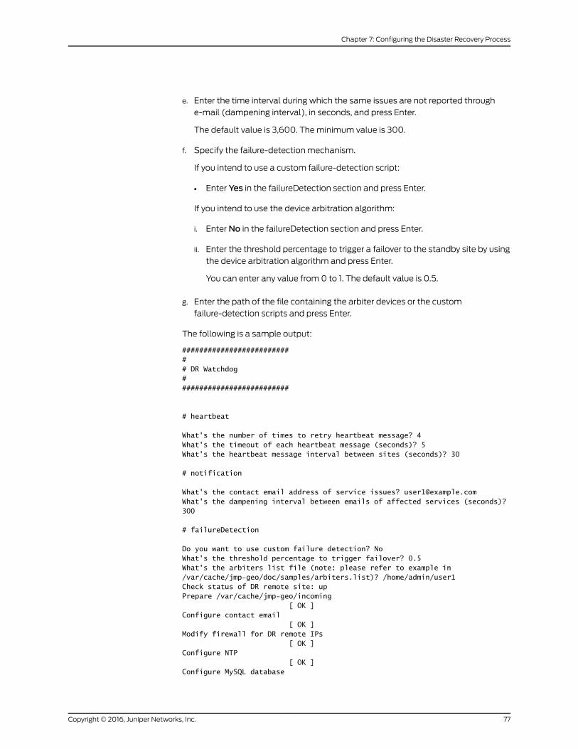
e. Enter the time interval during which the same issues are not reported through
e-mail (dampening interval), in seconds, and press Enter.
The default value is 3,600. The minimum value is 300.
f. Specify the failure-detection mechanism.
If you intend to use a custom failure-detection script:
• Enter Yes in the failureDetection section and press Enter.
If you intend to use the device arbitration algorithm:
i. Enter No in the failureDetection section and press Enter.
ii. Enter the threshold percentage to trigger a failover to the standby site by using
the device arbitration algorithm and press Enter.
You can enter any value from 0 to 1. The default value is 0.5.
g. Enter the path of the file containing the arbiter devices or the custom
failure-detection scripts and press Enter.
The following is a sample output:
########################### DR Watchdog##########################
# heartbeat
What's the number of times to retry heartbeat message? 4What's the timeout of each heartbeat message (seconds)? 5What's the heartbeat message interval between sites (seconds)? 30
# notification
What's the contact email address of service issues? [email protected]'s the dampening interval between emails of affected services (seconds)? 300
# failureDetection
Do you want to use custom failure detection? NoWhat's the threshold percentage to trigger failover? 0.5What's the arbiters list file (note: please refer to example in /var/cache/jmp-geo/doc/samples/arbiters.list)? /home/admin/user1Check status of DR remote site: upPrepare /var/cache/jmp-geo/incoming [ OK ]Configure contact email [ OK ]Modify firewall for DR remote IPs [ OK ]Configure NTP [ OK ]Configure MySQL database
77Copyright © 2016, Juniper Networks, Inc.
Chapter 7: Configuring the Disaster Recovery Process
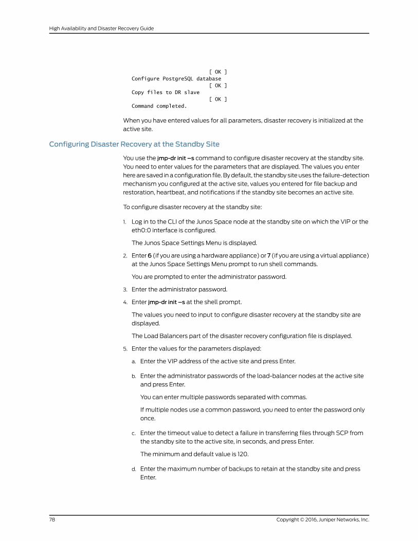
[ OK ]Configure PostgreSQL database [ OK ]Copy files to DR slave [ OK ]Command completed.
When you have entered values for all parameters, disaster recovery is initialized at the
active site.
Configuring Disaster Recovery at the Standby Site
You use the jmp-dr init –s command to configure disaster recovery at the standby site.
You need to enter values for the parameters that are displayed. The values you enter
here are saved in a configuration file. By default, the standby site uses the failure-detection
mechanism you configured at the active site, values you entered for file backup and
restoration, heartbeat, and notifications if the standby site becomes an active site.
To configure disaster recovery at the standby site:
1. Log in to the CLI of the Junos Space node at the standby site on which the VIP or the
eth0:0 interface is configured.
The Junos Space Settings Menu is displayed.
2. Enter6 (if you are using a hardware appliance) or7 (if you are using a virtual appliance)
at the Junos Space Settings Menu prompt to run shell commands.
You are prompted to enter the administrator password.
3. Enter the administrator password.
4. Enter jmp-dr init –s at the shell prompt.
The values you need to input to configure disaster recovery at the standby site are
displayed.
The Load Balancers part of the disaster recovery configuration file is displayed.
5. Enter the values for the parameters displayed:
a. Enter the VIP address of the active site and press Enter.
b. Enter the administrator passwords of the load-balancer nodes at the active site
and press Enter.
You can enter multiple passwords separated with commas.
If multiple nodes use a common password, you need to enter the password only
once.
c. Enter the timeout value to detect a failure in transferring files through SCP from
the standby site to the active site, in seconds, and press Enter.
The minimum and default value is 120.
d. Enter the maximum number of backups to retain at the standby site and press
Enter.
Copyright © 2016, Juniper Networks, Inc.78
High Availability and Disaster Recovery Guide
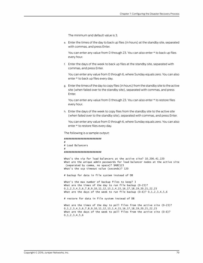
The minimum and default value is 3.
e. Enter the times of the day to back up files (in hours) at the standby site, separated
with commas, and press Enter.
You can enter any value from 0 through 23. You can also enter * to back up files
every hour.
f. Enter the days of the week to back up files at the standby site, separated with
commas, and press Enter.
You can enter any value from 0 through 6, where Sunday equals zero. You can also
enter * to back up files every day.
g. Enter the times of the day to copy files (in hours) from the standby site to the active
site (when failed over to the standby site), separated with commas, and press
Enter.
You can enter any value from 0 through 23. You can also enter * to restore files
every hour.
h. Enter the days of the week to copy files from the standby site to the active site
(when failed over to the standby site), separated with commas, and press Enter.
You can enter any value from 0 through 6, where Sunday equals zero. You can also
enter * to restore files every day.
The following is a sample output:
########################### Load Balancers##########################
What's the vip for load balancers at the active site? 10.206.41.220What are the unique admin passwords for load balancer nodes at the active site (separated by comma, no space)? $ABC123What's the scp timeout value (seconds)? 120
# backup for data in file system instead of DB
What's the max number of backup files to keep? 3What are the times of the day to run file backup (0-23)? 0,1,2,3,4,5,6,7,8,9,10,11,12,13,1,4,15,16,17,18,19,20,21,22,23What are the days of the week to run file backup (0-6)? 0,1,2,3,4,5,6
# restore for data in file system instead of DB
What are the times of the day to poll files from the active site (0-23)? 0,1,2,3,4,5,6,7,8,9,10,11,12,13,1,4,15,16,17,18,19,20,21,22,23What are the days of the week to poll files from the active site (0-6)? 0,1,2,3,4,5,6
79Copyright © 2016, Juniper Networks, Inc.
Chapter 7: Configuring the Disaster Recovery Process
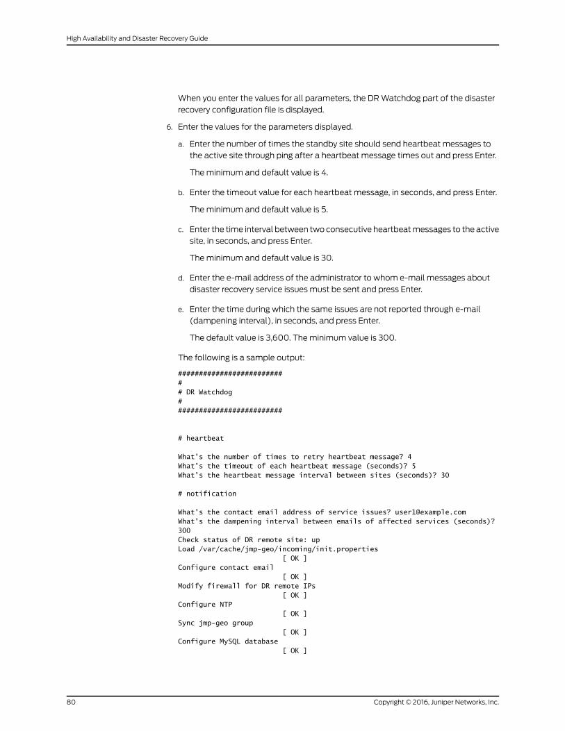
When you enter the values for all parameters, the DR Watchdog part of the disaster
recovery configuration file is displayed.
6. Enter the values for the parameters displayed.
a. Enter the number of times the standby site should send heartbeat messages to
the active site through ping after a heartbeat message times out and press Enter.
The minimum and default value is 4.
b. Enter the timeout value for each heartbeat message, in seconds, and press Enter.
The minimum and default value is 5.
c. Enter the time interval between two consecutive heartbeat messages to the active
site, in seconds, and press Enter.
The minimum and default value is 30.
d. Enter the e-mail address of the administrator to whom e-mail messages about
disaster recovery service issues must be sent and press Enter.
e. Enter the time during which the same issues are not reported through e-mail
(dampening interval), in seconds, and press Enter.
The default value is 3,600. The minimum value is 300.
The following is a sample output:
########################### DR Watchdog##########################
# heartbeat
What's the number of times to retry heartbeat message? 4What's the timeout of each heartbeat message (seconds)? 5What's the heartbeat message interval between sites (seconds)? 30
# notification
What's the contact email address of service issues? [email protected]'s the dampening interval between emails of affected services (seconds)? 300Check status of DR remote site: upLoad /var/cache/jmp-geo/incoming/init.properties [ OK ]Configure contact email [ OK ]Modify firewall for DR remote IPs [ OK ]Configure NTP [ OK ]Sync jmp-geo group [ OK ]Configure MySQL database [ OK ]
Copyright © 2016, Juniper Networks, Inc.80
High Availability and Disaster Recovery Guide

Configure PostgreSQL database [ OK ]Command completed.
When you have entered values for all parameters, disaster recovery is initialized at the
standby site.
Starting the Disaster Recovery Process
You use the jmp-dr start command to start the disaster recovery process at both sites.
You can also use the jmp-dr start-a command to start the disaster recovery process on
the active site and the jmp-dr start-s command to start the disaster recovery process on
the standby site.
To start the disaster recovery process:
1. Log in to the CLI of the Junos Space node at the active site on which the VIP or the
eth0:0 interface is configured.
The Junos Space Settings Menu is displayed.
2. Enter6 (if you are using a hardware appliance) or7 (if you are using a virtual appliance)
at the Junos Space Settings Menu prompt to run shell commands.
You are prompted to enter the administrator password.
3. Enter the administrator password.
4. Enter jmp-dr start at the shell prompt.
The disaster recovery process is initiated on both sites.
The following is a sample output at the active site:
[user1@host]# jmp-dr startStop dr-watchdog if it's running [ OK ]Check status of DR remote site: upCheck current DR role: active
INFO: => start DR at current site: active
Add device management IPs of DR remote site to up devices [ OK ]Setup MySQL replication: master-master [ OK ]Start MySQL dump [ OK ]Setup PostgreSQL replication [ OK ]Start file & RRD replication [ OK ]Open firewall for device traffic [ OK ]Start services(jboss,jboss-dc,etc.) [ OK ]Start dr-watchdog [ OK ]Copy files to DR slave site [ OK ]
81Copyright © 2016, Juniper Networks, Inc.
Chapter 7: Configuring the Disaster Recovery Process
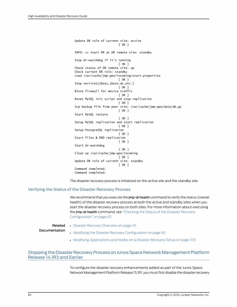
Update DR role of current site: active [ OK ]
INFO: => start DR at DR remote site: standby
Stop dr-watchdog if it's running [ OK ]Check status of DR remote site: upCheck current DR role: standbyLoad /var/cache/jmp-geo/incoming/start.properties [ OK ]Stop services(jboss,jboss-dc,etc.) [ OK ]Block firewall for device traffic [ OK ]Reset MySQL init script and stop replication [ OK ]Scp backup file from peer site: /var/cache/jmp-geo/data/db.gz [ OK ]Start MySQL restore [ OK ]Setup MySQL replication and start replication [ OK ]Setup PostgreSQL replication [ OK ]Start files & RRD replication [ OK ]Start dr-watchdog [ OK ]Clean up /var/cache/jmp-geo/incoming [ OK ]Update DR role of current site: standby [ OK ]Command completed.Command completed.
The disaster recovery process is initialized on the active site and the standby site.
Verifying the Status of the Disaster Recovery Process
We recommend that you execute the jmp-drhealth command to verify the status (overall
health) of the disaster recovery process at both the active and standby sites when you
start the disaster recovery process on both sites. For more information about executing
the jmp-dr health command, see “Checking the Status of the Disaster Recovery
Configuration” on page 87.
RelatedDocumentation
Disaster Recovery Overview on page 45•
• Modifying the Disaster Recovery Configuration on page 92
• Modifying Applications and Nodes on a Disaster Recovery Setup on page 105
StoppingtheDisasterRecoveryProcessonJunosSpaceNetworkManagementPlatformRelease 14.1R3 and Earlier
To configure the disaster recovery enhancements added as part of the Junos Space
Network Management Platform Release 15.1R1, you must first disable the disaster recovery
Copyright © 2016, Juniper Networks, Inc.82
High Availability and Disaster Recovery Guide
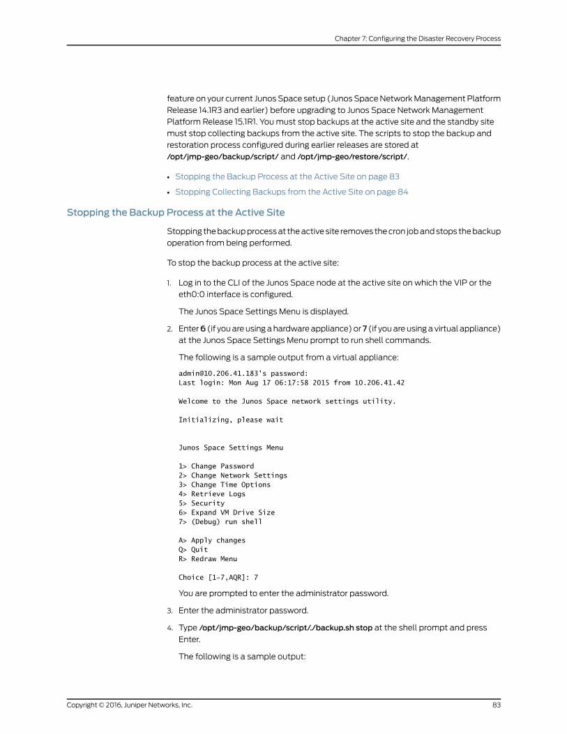
feature on your current Junos Space setup (Junos Space Network Management Platform
Release 14.1R3 and earlier) before upgrading to Junos Space Network Management
Platform Release 15.1R1. You must stop backups at the active site and the standby site
must stop collecting backups from the active site. The scripts to stop the backup and
restoration process configured during earlier releases are stored at
/opt/jmp-geo/backup/script/ and /opt/jmp-geo/restore/script/.
• Stopping the Backup Process at the Active Site on page 83
• Stopping Collecting Backups from the Active Site on page 84
Stopping the Backup Process at the Active Site
Stopping the backup process at the active site removes the cron job and stops the backup
operation from being performed.
To stop the backup process at the active site:
1. Log in to the CLI of the Junos Space node at the active site on which the VIP or the
eth0:0 interface is configured.
The Junos Space Settings Menu is displayed.
2. Enter6 (if you are using a hardware appliance) or7 (if you are using a virtual appliance)
at the Junos Space Settings Menu prompt to run shell commands.
The following is a sample output from a virtual appliance:
[email protected]'s password:Last login: Mon Aug 17 06:17:58 2015 from 10.206.41.42
Welcome to the Junos Space network settings utility.
Initializing, please wait
Junos Space Settings Menu
1> Change Password2> Change Network Settings3> Change Time Options4> Retrieve Logs5> Security6> Expand VM Drive Size7> (Debug) run shell
A> Apply changesQ> QuitR> Redraw Menu
Choice [1-7,AQR]: 7
You are prompted to enter the administrator password.
3. Enter the administrator password.
4. Type /opt/jmp-geo/backup/script/./backup.sh stop at the shell prompt and press
Enter.
The following is a sample output:
83Copyright © 2016, Juniper Networks, Inc.
Chapter 7: Configuring the Disaster Recovery Process

Demoting this cluster from the DR Master Cluster Role ...update cluster state successfulStoping backup cron job...Stopping crond: [ OK ]Starting crond: [ OK ]
The backup process at the active site is stopped.
Stopping Collecting Backups from the Active Site
Stopping the restoration process at the standby site removes the cron job and stops
collecting backups from the active site.
To stop the restoration process at the standby site:
1. Log in to the CLI of the Junos Space node at the active site on which the VIP or the
eth0:0 interface is configured.
The Junos Space Settings Menu is displayed.
2. Enter6 (if you are using a hardware appliance) or7 (if you are using a virtual appliance)
at the Junos Space Settings Menu prompt to run shell commands.
The following is a sample output from a virtual appliance:
[email protected]'s password:Last login: Mon Aug 17 06:17:58 2015 from 10.206.41.42
Welcome to the Junos Space network settings utility.
Initializing, please wait
Junos Space Settings Menu
1> Change Password2> Change Network Settings3> Change Time Options4> Retrieve Logs5> Security6> Expand VM Drive Size7> (Debug) run shell
A> Apply changesQ> QuitR> Redraw Menu
Choice [1-7,AQR]: 7
You are prompted to enter the administrator password.
3. Enter the administrator password.
4. Type /opt/jmp-geo/restore/script/./restore.sh stopPoll at the shell prompt and press
Enter.
The following is a sample output:
Stoping restore cron job...Stopping crond: [ OK ]Starting crond: [ OK ]
Copyright © 2016, Juniper Networks, Inc.84
High Availability and Disaster Recovery Guide

Demoting this cluster from the DR Slave Cluster Role ...update cluster state successfulopening port 7804 on [email protected] is stopped. Skip reloading<response><message</message><status>SUCCESS</success></response>
The standby site stops collecting backups from the active site.
RelatedDocumentation
• Disaster Recovery Overview on page 45
• Configuring the Disaster Recovery Process Between an Active and a Standby Site on
page 73
85Copyright © 2016, Juniper Networks, Inc.
Chapter 7: Configuring the Disaster Recovery Process

Copyright © 2016, Juniper Networks, Inc.86
High Availability and Disaster Recovery Guide
CHAPTER 8
Managing the Disaster Recovery Solution
• Checking the Status of the Disaster Recovery Configuration on page 87
• Viewing the Disaster Recovery Configuration and Status of Watchdog
Services on page 91
• Modifying the Disaster Recovery Configuration on page 92
• Modifying Applications and Nodes on a Disaster Recovery Setup on page 105
• Manually Failing Over the Network Management Services to the Standby Site on page 116
• Stopping the Disaster Recovery Process on page 118
• Resetting the Disaster Recovery Configuration on page 119
Checking the Status of the Disaster Recovery Configuration
You check the status of the disaster recovery configuration:
• After starting the disaster recovery process to ensure that the disaster recovery
configuration is accurate, files are being replicated, and the disaster recovery watchdog
is monitoring the disaster recovery setup
• After stopping the disaster recovery process, to ensure that file replication and disaster
recovery watchdog process have stopped
You execute the jmp-dr health command to check the status of the disaster recovery
configuration. This command checks the status of asynchronous data replication, file
transfer, and disaster recovery watchdog, and the role of clusters in the disaster recovery
setup. Errors found during command execution are listed in the command output.
NOTE: If you have already executed the jmp-dr health command and the
execution is inprogress,executinganother jmp-drhealthcommandcandisplay
incorrect output. The output from the jmp-dr health command also lists
whether another instance of the command is being executed.
87Copyright © 2016, Juniper Networks, Inc.

To check the status of the disaster recovery configuration at a site:
1. Log in to the CLI of the Junos Space node at the site on which the VIP or the eth0:0
interface is configured.
The Junos Space Settings Menu is displayed.
2. Enter6 (if you are using a hardware appliance) or7 (if you are using a virtual appliance)
at the Junos Space Settings Menu prompt to run shell commands.
The following is a sample output from a virtual appliance:
[email protected]'s password:Last login: Mon Aug 17 06:17:58 2015 from 10.206.41.42
Welcome to the Junos Space network settings utility.
Initializing, please wait
Junos Space Settings Menu
1> Change Password2> Change Network Settings3> Change Time Options4> Retrieve Logs5> Security6> Expand VM Drive Size7> (Debug) run shell
A> Apply changesQ> QuitR> Redraw Menu
Choice [1-7,AQR]: 7
You are prompted to enter the administrator password.
3. Enter the administrator password.
4. Enter jmp-dr health at the shell prompt.
Junos Space Platform checks the status (overall health) of the disaster recovery
configuration at the site.
• The following is a sample output of the jmp-dr health command after you start the
disaster recovery process and execute the command at the active site:
[user1@host]# jmp-dr healthThe DR role of this site: activeThe DR state of this site: startedThe status of DR watchdog: readyThe status of DR remote site: upCheck admin password of DR remote site [ OK ]Check mysql ca and server certificates [ OK ]Check mysql replication users [ OK ]Check file replication: backup cron job should be added [ OK ]Check mysql replication:
Copyright © 2016, Juniper Networks, Inc.88
High Availability and Disaster Recovery Guide
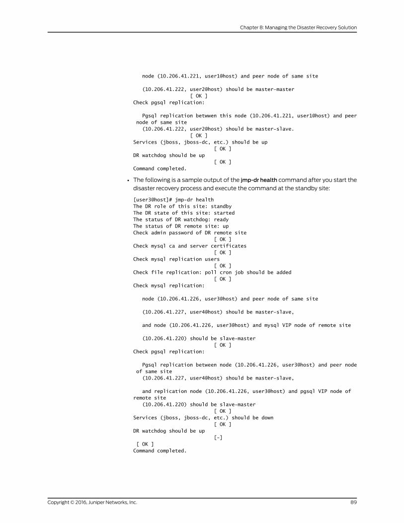
node (10.206.41.221, user1@host) and peer node of same site
(10.206.41.222, user2@host) should be master-master [ OK ]Check pgsql replication:
Pgsql replication betwwen this node (10.206.41.221, user1@host) and peer node of same site (10.206.41.222, user2@host) should be master-slave. [ OK ]Services (jboss, jboss-dc, etc.) should be up [ OK ]DR watchdog should be up [ OK ]Command completed.
• The following is a sample output of the jmp-dr health command after you start the
disaster recovery process and execute the command at the standby site:
[user3@host]# jmp-dr healthThe DR role of this site: standbyThe DR state of this site: startedThe status of DR watchdog: readyThe status of DR remote site: upCheck admin password of DR remote site [ OK ]Check mysql ca and server certificates [ OK ]Check mysql replication users [ OK ]Check file replication: poll cron job should be added [ OK ]Check mysql replication:
node (10.206.41.226, user3@host) and peer node of same site
(10.206.41.227, user4@host) should be master-slave,
and node (10.206.41.226, user3@host) and mysql VIP node of remote site
(10.206.41.220) should be slave-master [ OK ]Check pgsql replication:
Pgsql replication between node (10.206.41.226, user3@host) and peer node of same site (10.206.41.227, user4@host) should be master-slave,
and replication node (10.206.41.226, user3@host) and pgsql VIP node of remote site (10.206.41.220) should be slave-master [ OK ]Services (jboss, jboss-dc, etc.) should be down [ OK ]DR watchdog should be up [-] [ OK ]Command completed.
89Copyright © 2016, Juniper Networks, Inc.
Chapter 8: Managing the Disaster Recovery Solution
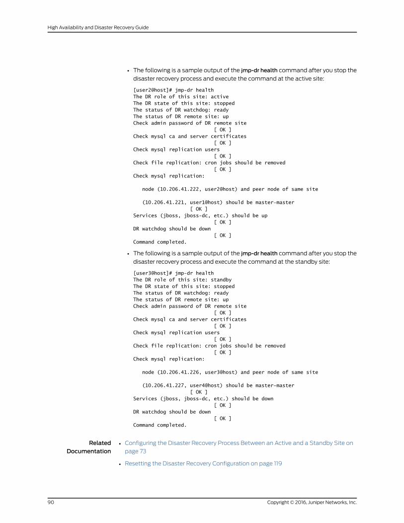
• The following is a sample output of the jmp-dr health command after you stop the
disaster recovery process and execute the command at the active site:
[user2@host]# jmp-dr healthThe DR role of this site: activeThe DR state of this site: stoppedThe status of DR watchdog: readyThe status of DR remote site: upCheck admin password of DR remote site [ OK ]Check mysql ca and server certificates [ OK ]Check mysql replication users [ OK ]Check file replication: cron jobs should be removed [ OK ]Check mysql replication:
node (10.206.41.222, user2@host) and peer node of same site
(10.206.41.221, user1@host) should be master-master [ OK ]Services (jboss, jboss-dc, etc.) should be up [ OK ]DR watchdog should be down [ OK ]Command completed.
• The following is a sample output of the jmp-dr health command after you stop the
disaster recovery process and execute the command at the standby site:
[user3@host]# jmp-dr healthThe DR role of this site: standbyThe DR state of this site: stoppedThe status of DR watchdog: readyThe status of DR remote site: upCheck admin password of DR remote site [ OK ]Check mysql ca and server certificates [ OK ]Check mysql replication users [ OK ]Check file replication: cron jobs should be removed [ OK ]Check mysql replication:
node (10.206.41.226, user3@host) and peer node of same site
(10.206.41.227, user4@host) should be master-master [ OK ]Services (jboss, jboss-dc, etc.) should be down [ OK ]DR watchdog should be down [ OK ]Command completed.
RelatedDocumentation
Configuring the Disaster Recovery Process Between an Active and a Standby Site on
page 73
•
• Resetting the Disaster Recovery Configuration on page 119
Copyright © 2016, Juniper Networks, Inc.90
High Availability and Disaster Recovery Guide
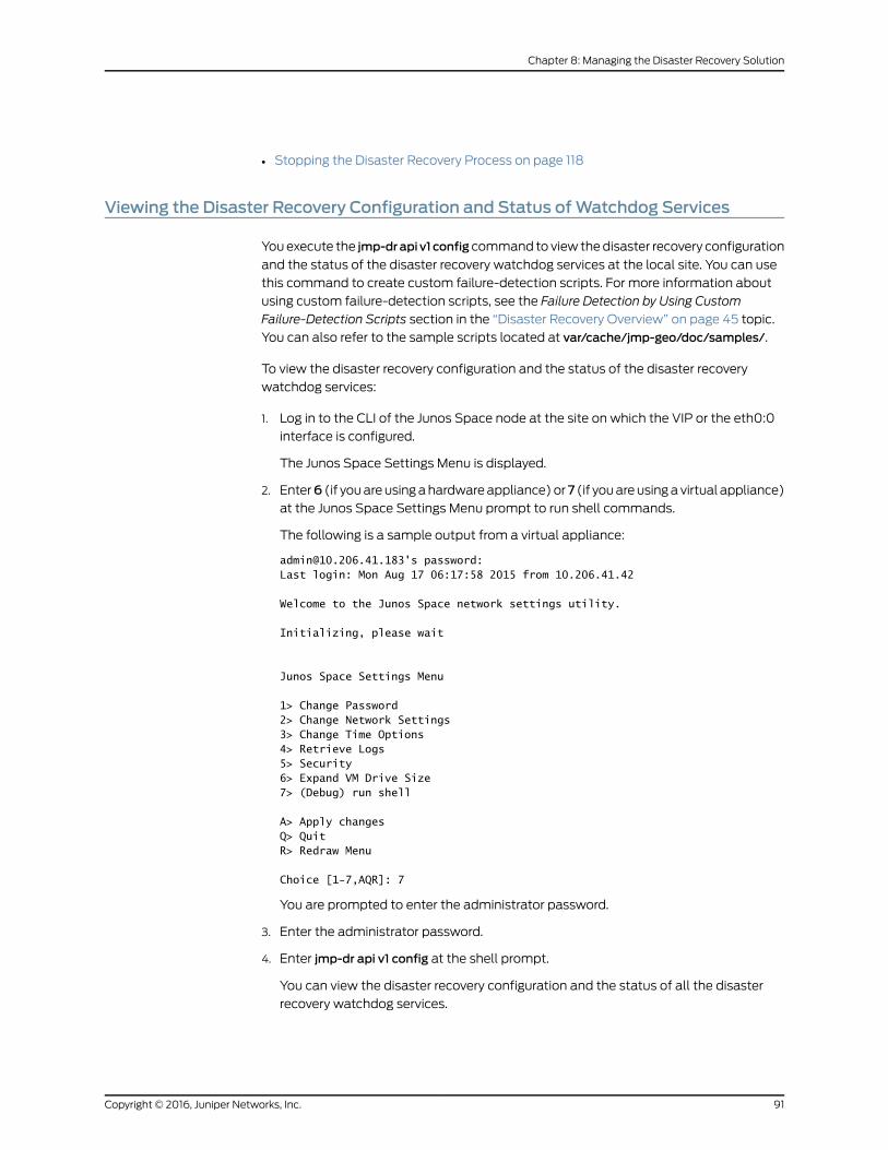
• Stopping the Disaster Recovery Process on page 118
Viewing the Disaster Recovery Configuration and Status ofWatchdog Services
You execute the jmp-drapi v1 config command to view the disaster recovery configuration
and the status of the disaster recovery watchdog services at the local site. You can use
this command to create custom failure-detection scripts. For more information about
using custom failure-detection scripts, see the Failure Detection by Using Custom
Failure-Detection Scripts section in the “Disaster Recovery Overview” on page 45 topic.
You can also refer to the sample scripts located at var/cache/jmp-geo/doc/samples/.
To view the disaster recovery configuration and the status of the disaster recovery
watchdog services:
1. Log in to the CLI of the Junos Space node at the site on which the VIP or the eth0:0
interface is configured.
The Junos Space Settings Menu is displayed.
2. Enter6 (if you are using a hardware appliance) or7 (if you are using a virtual appliance)
at the Junos Space Settings Menu prompt to run shell commands.
The following is a sample output from a virtual appliance:
[email protected]'s password:Last login: Mon Aug 17 06:17:58 2015 from 10.206.41.42
Welcome to the Junos Space network settings utility.
Initializing, please wait
Junos Space Settings Menu
1> Change Password2> Change Network Settings3> Change Time Options4> Retrieve Logs5> Security6> Expand VM Drive Size7> (Debug) run shell
A> Apply changesQ> QuitR> Redraw Menu
Choice [1-7,AQR]: 7
You are prompted to enter the administrator password.
3. Enter the administrator password.
4. Enter jmp-dr api v1 config at the shell prompt.
You can view the disaster recovery configuration and the status of all the disaster
recovery watchdog services.
91Copyright © 2016, Juniper Networks, Inc.
Chapter 8: Managing the Disaster Recovery Solution
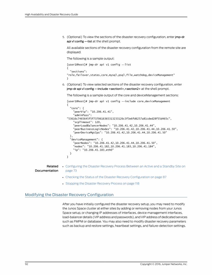
5. (Optional) To view the sections of the disaster recovery configuration, enter jmp-dr
api v1 config –-list at the shell prompt.
All available sections of the disaster recovery configuration from the remote site are
displayed.
The following is a sample output:
[user1@host]# jmp-dr api v1 config --list{ "sections": "role,failover,states,core,mysql,psql,file,watchdog,deviceManagement"}
6. (Optional) To view selected sections of the disaster recovery configuration, enter
jmp-dr api v1 config –-include <section1>,<section2> at the shell prompt.
The following is a sample output of the core and deviceManagement sections:
[user1@host]# jmp-dr api v1 config --include core,deviceManagement{ "core": { "peerVip": "10.206.41.41", "adminPass": "53616c7465645f5f7370616365313233126c3f3e6fd6257a81cded28f55d465c", "scpTimeout": 120, "peerLoadBalancerNodes": "10.206.41.42,10.206.41.44", "peerBusinessLogicNodes": "10.206.41.42,10.206.41.44,10.206.41.50", "peerDeviceMgtIps": "10.206.41.42,10.206.41.44,10.206.41.50" }, "deviceManagement": { "peerNodes": "10.206.41.42,10.206.41.44,10.206.41.50", "nodes": "10.206.41.182,10.206.41.183,10.206.41.184", "ip": "10.206.41.183,eth0" }}
RelatedDocumentation
Configuring the Disaster Recovery Process Between an Active and a Standby Site on
page 73
•
• Checking the Status of the Disaster Recovery Configuration on page 87
• Stopping the Disaster Recovery Process on page 118
Modifying the Disaster Recovery Configuration
After you have initially configured the disaster recovery setup, you may need to modify
the Junos Space cluster at either sites by adding or removing nodes from your Junos
Space setup, or changing IP addresses of interfaces, device management interfaces,
load-balancer details (VIP address and passwords), and VIP address of dedicated services
such as FMPM or database. You may also need to modify disaster recovery parameters
such as backup and restore settings, heartbeat settings, and failure-detection settings.
Copyright © 2016, Juniper Networks, Inc.92
High Availability and Disaster Recovery Guide
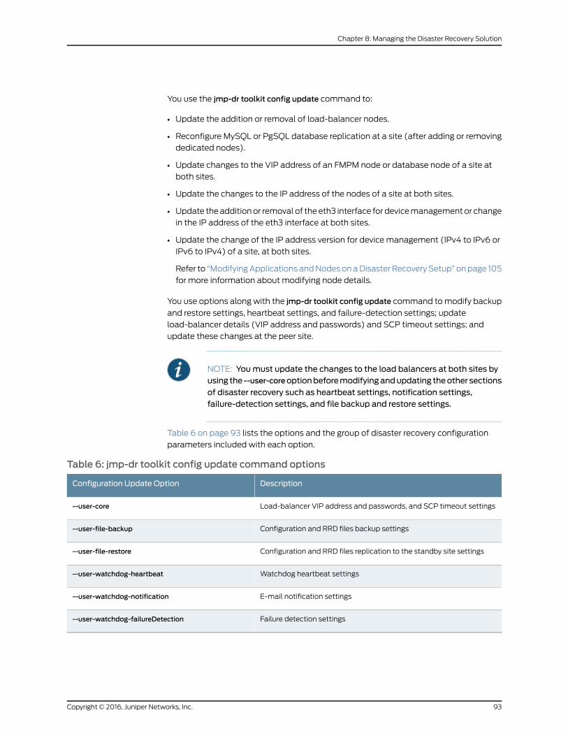
You use the jmp-dr toolkit config update command to:
• Update the addition or removal of load-balancer nodes.
• Reconfigure MySQL or PgSQL database replication at a site (after adding or removing
dedicated nodes).
• Update changes to the VIP address of an FMPM node or database node of a site at
both sites.
• Update the changes to the IP address of the nodes of a site at both sites.
• Update the addition or removal of the eth3 interface for device management or change
in the IP address of the eth3 interface at both sites.
• Update the change of the IP address version for device management (IPv4 to IPv6 or
IPv6 to IPv4) of a site, at both sites.
Refer to “Modifying Applications and Nodes on a Disaster Recovery Setup” on page 105
for more information about modifying node details.
You use options along with the jmp-dr toolkit config update command to modify backup
and restore settings, heartbeat settings, and failure-detection settings; update
load-balancer details (VIP address and passwords) and SCP timeout settings; and
update these changes at the peer site.
NOTE: Youmust update the changes to the load balancers at both sites byusing the --user-coreoptionbeforemodifyingandupdating theother sections
of disaster recovery such as heartbeat settings, notification settings,failure-detection settings, and file backup and restore settings.
Table 6 on page 93 lists the options and the group of disaster recovery configuration
parameters included with each option.
Table 6: jmp-dr toolkit config update command options
DescriptionConfiguration Update Option
Load-balancer VIP address and passwords, and SCP timeout settings--user-core
Configuration and RRD files backup settings--user-file-backup
Configuration and RRD files replication to the standby site settings--user-file-restore
Watchdog heartbeat settings--user-watchdog-heartbeat
E-mail notification settings--user-watchdog-notification
Failure detection settings--user-watchdog-failureDetection
93Copyright © 2016, Juniper Networks, Inc.
Chapter 8: Managing the Disaster Recovery Solution
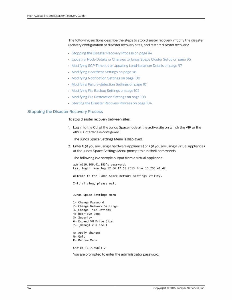
The following sections describe the steps to stop disaster recovery, modify the disaster
recovery configuration at disaster recovery sites, and restart disaster recovery:
• Stopping the Disaster Recovery Process on page 94
• Updating Node Details or Changes to Junos Space Cluster Setup on page 95
• Modifying SCP Timeout or Updating Load-balancer Details on page 97
• Modifying Heartbeat Settings on page 98
• Modifying Notification Settings on page 100
• Modifying Failure-detection Settings on page 101
• Modifying File Backup Settings on page 102
• Modifying File Restoration Settings on page 103
• Starting the Disaster Recovery Process on page 104
Stopping the Disaster Recovery Process
To stop disaster recovery between sites:
1. Log in to the CLI of the Junos Space node at the active site on which the VIP or the
eth0:0 interface is configured.
The Junos Space Settings Menu is displayed.
2. Enter6 (if you are using a hardware appliance) or7 (if you are using a virtual appliance)
at the Junos Space Settings Menu prompt to run shell commands.
The following is a sample output from a virtual appliance:
[email protected]'s password:Last login: Mon Aug 17 06:17:58 2015 from 10.206.41.42
Welcome to the Junos Space network settings utility.
Initializing, please wait
Junos Space Settings Menu
1> Change Password2> Change Network Settings3> Change Time Options4> Retrieve Logs5> Security6> Expand VM Drive Size7> (Debug) run shell
A> Apply changesQ> QuitR> Redraw Menu
Choice [1-7,AQR]: 7
You are prompted to enter the administrator password.
Copyright © 2016, Juniper Networks, Inc.94
High Availability and Disaster Recovery Guide

3. Enter the administrator password.
4. Stop the disaster recovery process on both sites. To do so, type jmp-dr stop at the
shell prompt and press Enter.
Updating Node Details or Changes to Junos Space Cluster Setup
To update the modification to node details or Junos Space cluster setup:
1. Log in to the CLI of the Junos Space VIP node at the site where you made the
modifications.
The Junos Space Settings Menu is displayed.
2. Enter6 (if you are using a hardware appliance) or7 (if you are using a virtual appliance)
at the Junos Space Settings Menu prompt to run shell commands.
You are prompted to enter the administrator password.
3. Enter the administrator password.
4. Type jmp-dr toolkit config update at the shell prompt and press Enter.
You are prompted to use the jmp-dr toolkit config update --user-core command.
5. Type No and press Enter to view the cluster modifications.
The modified cluster configuration is displayed in the JSON format.
6. Press Enter to accept the changes.
The following is a sample output when the disaster recovery configuration is updated
after adding a dedicated MySQL node.
[user1@host]# jmp-dr toolkit config update If admin password of any node belonging to remote site is changed or if a new node with different admin password is added then please use option --user-core. Continue? YesThe modified user configuration in JSON format is as follows:{ "user_mysql_hasDedicatedDb": { "lhs": false, "rhs": true }, "user_mysql_peerVip": { "lhs": "10.206.41.225", "rhs": "10.206.41.84" }, "user_mysql_peerNodes": { "lhs": "10.206.41.226,10.206.41.227", "rhs": "10.206.41.85,10.206.41.86" }}
Do you want to apply these changes? YesCheck status of DR remote site: upStop mysql replication if applicable [ OK ]Update mysql repUser & repAdmin [ OK ]Update firewall
95Copyright © 2016, Juniper Networks, Inc.
Chapter 8: Managing the Disaster Recovery Solution

[ OK ]Update ntp [ OK ]Update mysql configuration if applicable [ OK ]Update services (such as jboss-dc, httpd, etc.) [ OK ]The configuration change is updated only at current site, please ensure to update at the remote site accordingly.The `toolkit config` command is done
The disaster recovery configuration file at the local site is updated with the modified
configuration of the cluster.
7. Log in to the CLI of the Junos Space VIP node at the remote site to update the
modifications made at the local site.
The Junos Space Settings Menu is displayed.
8. Enter6 (if you are using a hardware appliance) or7 (if you are using a virtual appliance)
at the Junos Space Settings Menu prompt to run shell commands.
You are prompted to enter the administrator password.
9. Enter the administrator password.
10. Type jmp-dr toolkit config update at the shell prompt and press Enter.
You are prompted to use the jmp-dr toolkit config update --user-core command.
11. Type No and press Enter to view the modified cluster configuration at the remote site.
The modified configuration is displayed in the JSON format.
12. Press Enter to accept the changes.
The disaster recovery configuration file at the remote site is updated with the modified
configuration of the cluster at the local site.
Copyright © 2016, Juniper Networks, Inc.96
High Availability and Disaster Recovery Guide
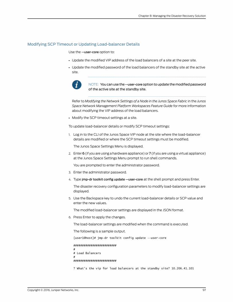
Modifying SCP Timeout or Updating Load-balancer Details
Use the --user-core option to:
• Update the modified VIP address of the load balancers of a site at the peer site.
• Update the modified password of the load balancers of the standby site at the active
site.
NOTE: Youcanuse the --user-coreoption toupdate themodifiedpassword
of the active site at the standby site.
Refer toModifying the Network Settings of a Node in the Junos Space Fabric in the Junos
Space Network Management PlatformWorkspaces Feature Guide for more information
about modifying the VIP address of the load balancers.
• Modify the SCP timeout settings at a site.
To update load-balancer details or modify SCP timeout settings:
1. Log in to the CLI of the Junos Space VIP node at the site where the load-balancer
details are modified or where the SCP timeout settings must be modified.
The Junos Space Settings Menu is displayed.
2. Enter6 (if you are using a hardware appliance) or7 (if you are using a virtual appliance)
at the Junos Space Settings Menu prompt to run shell commands.
You are prompted to enter the administrator password.
3. Enter the administrator password.
4. Type jmp-dr toolkit config update --user-core at the shell prompt and press Enter.
The disaster recovery configuration parameters to modify load-balancer settings are
displayed.
5. Use the Backspace key to undo the current load-balancer details or SCP value and
enter the new values.
The modified load-balancer settings are displayed in the JSON format.
6. Press Enter to apply the changes.
The load-balancer settings are modified when the command is executed.
The following is a sample output.
[user1@host]# jmp-dr toolkit config update --user-core
########################### Load Balancers##########################
? What's the vip for load balancers at the standby site? 10.206.41.101
97Copyright © 2016, Juniper Networks, Inc.
Chapter 8: Managing the Disaster Recovery Solution
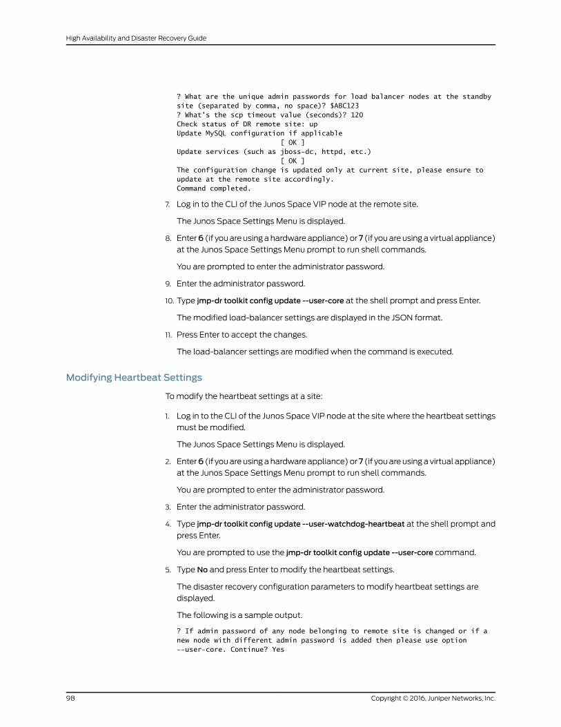
? What are the unique admin passwords for load balancer nodes at the standby site (separated by comma, no space)? $ABC123? What's the scp timeout value (seconds)? 120Check status of DR remote site: upUpdate MySQL configuration if applicable [ OK ]Update services (such as jboss-dc, httpd, etc.) [ OK ]The configuration change is updated only at current site, please ensure to update at the remote site accordingly.Command completed.
7. Log in to the CLI of the Junos Space VIP node at the remote site.
The Junos Space Settings Menu is displayed.
8. Enter6 (if you are using a hardware appliance) or7 (if you are using a virtual appliance)
at the Junos Space Settings Menu prompt to run shell commands.
You are prompted to enter the administrator password.
9. Enter the administrator password.
10. Type jmp-dr toolkit config update --user-core at the shell prompt and press Enter.
The modified load-balancer settings are displayed in the JSON format.
11. Press Enter to accept the changes.
The load-balancer settings are modified when the command is executed.
Modifying Heartbeat Settings
To modify the heartbeat settings at a site:
1. Log in to the CLI of the Junos Space VIP node at the site where the heartbeat settings
must be modified.
The Junos Space Settings Menu is displayed.
2. Enter6 (if you are using a hardware appliance) or7 (if you are using a virtual appliance)
at the Junos Space Settings Menu prompt to run shell commands.
You are prompted to enter the administrator password.
3. Enter the administrator password.
4. Type jmp-dr toolkit config update --user-watchdog-heartbeat at the shell prompt and
press Enter.
You are prompted to use the jmp-dr toolkit config update --user-core command.
5. Type No and press Enter to modify the heartbeat settings.
The disaster recovery configuration parameters to modify heartbeat settings are
displayed.
The following is a sample output.
? If admin password of any node belonging to remote site is changed or if a new node with different admin password is added then please use option --user-core. Continue? Yes
Copyright © 2016, Juniper Networks, Inc.98
High Availability and Disaster Recovery Guide
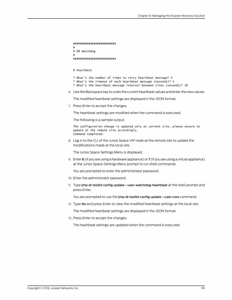
########################### DR Watchdog##########################
# heartbeat
? What's the number of times to retry heartbeat message? 4? What's the timeout of each heartbeat message (seconds)? 5? What's the heartbeat message interval between sites (seconds)? 30
6. Use the Backspace key to undo the current heartbeat values and enter the new values.
The modified heartbeat settings are displayed in the JSON format.
7. Press Enter to accept the changes.
The heartbeat settings are modified when the command is executed.
The following is a sample output.
The configuration change is updated only at current site, please ensure to update at the remote site accordingly.Command completed.
8. Log in to the CLI of the Junos Space VIP node at the remote site to update the
modifications made at the local site.
The Junos Space Settings Menu is displayed.
9. Enter6 (if you are using a hardware appliance) or7 (if you are using a virtual appliance)
at the Junos Space Settings Menu prompt to run shell commands.
You are prompted to enter the administrator password.
10. Enter the administrator password.
11. Type jmp-dr toolkit config update --user-watchdog-heartbeat at the shell prompt and
press Enter.
You are prompted to use the jmp-dr toolkit config update --user-core command.
12. Type No and press Enter to view the modified heartbeat settings at the local site.
The modified heartbeat settings are displayed in the JSON format.
13. Press Enter to accept the changes.
The heartbeat settings are updated when the command is executed.
99Copyright © 2016, Juniper Networks, Inc.
Chapter 8: Managing the Disaster Recovery Solution
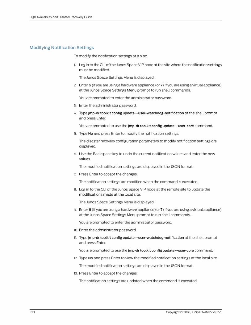
Modifying Notification Settings
To modify the notification settings at a site:
1. Log in to the CLI of the Junos Space VIP node at the site where the notification settings
must be modified.
The Junos Space Settings Menu is displayed.
2. Enter6 (if you are using a hardware appliance) or7 (if you are using a virtual appliance)
at the Junos Space Settings Menu prompt to run shell commands.
You are prompted to enter the administrator password.
3. Enter the administrator password.
4. Type jmp-dr toolkit config update --user-watchdog-notification at the shell prompt
and press Enter.
You are prompted to use the jmp-dr toolkit config update --user-core command.
5. Type No and press Enter to modify the notification settings.
The disaster recovery configuration parameters to modify notification settings are
displayed.
6. Use the Backspace key to undo the current notification values and enter the new
values.
The modified notification settings are displayed in the JSON format.
7. Press Enter to accept the changes.
The notification settings are modified when the command is executed.
8. Log in to the CLI of the Junos Space VIP node at the remote site to update the
modifications made at the local site.
The Junos Space Settings Menu is displayed.
9. Enter6 (if you are using a hardware appliance) or7 (if you are using a virtual appliance)
at the Junos Space Settings Menu prompt to run shell commands.
You are prompted to enter the administrator password.
10. Enter the administrator password.
11. Type jmp-dr toolkit config update --user-watchdog-notification at the shell prompt
and press Enter.
You are prompted to use the jmp-dr toolkit config update --user-core command.
12. Type No and press Enter to view the modified notification settings at the local site.
The modified notification settings are displayed in the JSON format.
13. Press Enter to accept the changes.
The notification settings are updated when the command is executed.
Copyright © 2016, Juniper Networks, Inc.100
High Availability and Disaster Recovery Guide
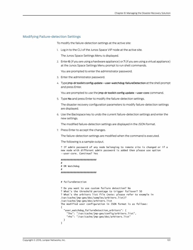
Modifying Failure-detection Settings
To modify the failure-detection settings at the active site:
1. Log in to the CLI of the Junos Space VIP node at the active site.
The Junos Space Settings Menu is displayed.
2. Enter6 (if you are using a hardware appliance) or7 (if you are using a virtual appliance)
at the Junos Space Settings Menu prompt to run shell commands.
You are prompted to enter the administrator password.
3. Enter the administrator password.
4. Type jmp-dr toolkit configupdate --user-watchdog-failureDetectionat the shell prompt
and press Enter.
You are prompted to use the jmp-dr toolkit config update --user-core command.
5. Type No and press Enter to modify the failure-detection settings.
The disaster recovery configuration parameters to modify failure-detection settings
are displayed.
6. Use the Backspace key to undo the current failure-detection settings and enter the
new settings.
The modified failure-detection settings are displayed in the JSON format.
7. Press Enter to accept the changes.
The failure-detection settings are modified when the command is executed.
The following is a sample output.
? If admin password of any node belonging to remote site is changed or if a new node with different admin password is added then please use option --user-core. Continue? Yes
########################### DR Watchdog##########################
# failureDetection
? Do you want to use custom failure detection? No? What's the threshold percentage to trigger failover? 50? What's the arbiters list file (note: please refer to example in /var/cache/jmp-geo/doc/samples/arbiters.list)? /var/cache/jmp-geo/doc/arbiters.listThe modified user configuration in JSON format is as follows:{ "user_watchdog_failureDetection_arbiters": { "lhs": "/var/cache/jmp-geo/config/arbiters.list", "rhs": "/var/cache/jmp-geo/doc/arbiters.list" }}
101Copyright © 2016, Juniper Networks, Inc.
Chapter 8: Managing the Disaster Recovery Solution
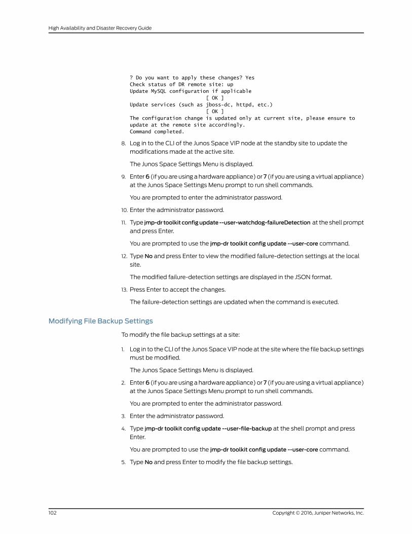
? Do you want to apply these changes? YesCheck status of DR remote site: upUpdate MySQL configuration if applicable [ OK ]Update services (such as jboss-dc, httpd, etc.) [ OK ]The configuration change is updated only at current site, please ensure to update at the remote site accordingly.Command completed.
8. Log in to the CLI of the Junos Space VIP node at the standby site to update the
modifications made at the active site.
The Junos Space Settings Menu is displayed.
9. Enter6 (if you are using a hardware appliance) or7 (if you are using a virtual appliance)
at the Junos Space Settings Menu prompt to run shell commands.
You are prompted to enter the administrator password.
10. Enter the administrator password.
11. Type jmp-dr toolkit configupdate--user-watchdog-failureDetection at the shell prompt
and press Enter.
You are prompted to use the jmp-dr toolkit config update --user-core command.
12. Type No and press Enter to view the modified failure-detection settings at the local
site.
The modified failure-detection settings are displayed in the JSON format.
13. Press Enter to accept the changes.
The failure-detection settings are updated when the command is executed.
Modifying File Backup Settings
To modify the file backup settings at a site:
1. Log in to the CLI of the Junos Space VIP node at the site where the file backup settings
must be modified.
The Junos Space Settings Menu is displayed.
2. Enter6 (if you are using a hardware appliance) or7 (if you are using a virtual appliance)
at the Junos Space Settings Menu prompt to run shell commands.
You are prompted to enter the administrator password.
3. Enter the administrator password.
4. Type jmp-dr toolkit config update --user-file-backup at the shell prompt and press
Enter.
You are prompted to use the jmp-dr toolkit config update --user-core command.
5. Type No and press Enter to modify the file backup settings.
Copyright © 2016, Juniper Networks, Inc.102
High Availability and Disaster Recovery Guide
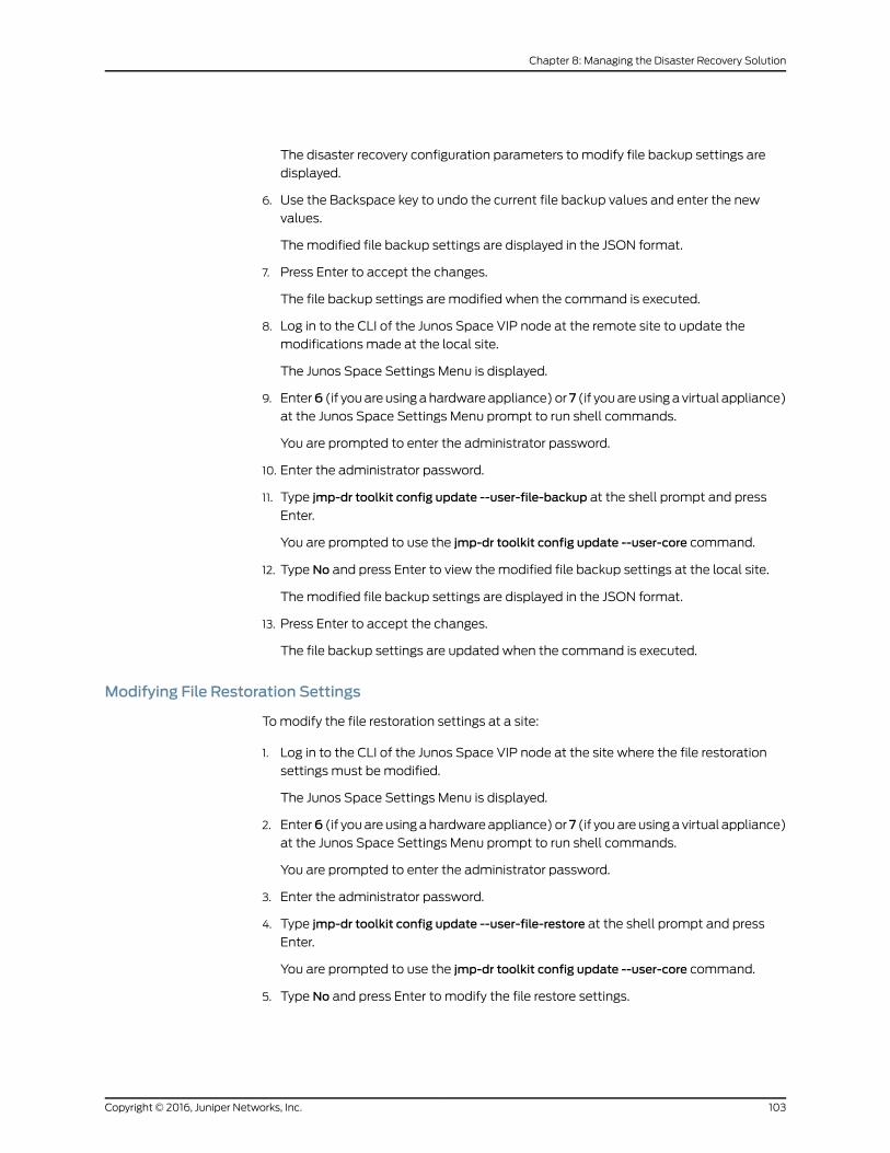
The disaster recovery configuration parameters to modify file backup settings are
displayed.
6. Use the Backspace key to undo the current file backup values and enter the new
values.
The modified file backup settings are displayed in the JSON format.
7. Press Enter to accept the changes.
The file backup settings are modified when the command is executed.
8. Log in to the CLI of the Junos Space VIP node at the remote site to update the
modifications made at the local site.
The Junos Space Settings Menu is displayed.
9. Enter6 (if you are using a hardware appliance) or7 (if you are using a virtual appliance)
at the Junos Space Settings Menu prompt to run shell commands.
You are prompted to enter the administrator password.
10. Enter the administrator password.
11. Type jmp-dr toolkit config update --user-file-backup at the shell prompt and press
Enter.
You are prompted to use the jmp-dr toolkit config update --user-core command.
12. Type No and press Enter to view the modified file backup settings at the local site.
The modified file backup settings are displayed in the JSON format.
13. Press Enter to accept the changes.
The file backup settings are updated when the command is executed.
Modifying File Restoration Settings
To modify the file restoration settings at a site:
1. Log in to the CLI of the Junos Space VIP node at the site where the file restoration
settings must be modified.
The Junos Space Settings Menu is displayed.
2. Enter6 (if you are using a hardware appliance) or7 (if you are using a virtual appliance)
at the Junos Space Settings Menu prompt to run shell commands.
You are prompted to enter the administrator password.
3. Enter the administrator password.
4. Type jmp-dr toolkit config update --user-file-restore at the shell prompt and press
Enter.
You are prompted to use the jmp-dr toolkit config update --user-core command.
5. Type No and press Enter to modify the file restore settings.
103Copyright © 2016, Juniper Networks, Inc.
Chapter 8: Managing the Disaster Recovery Solution
The disaster recovery configuration parameters to modify file restore settings are
displayed.
6. Use the Backspace key to undo the current file restore values and enter the new values.
The modified file restore settings are displayed in the JSON format.
7. Press Enter to accept the changes.
The file restore settings are modified when the command is executed.
8. Log in to the CLI of the Junos Space VIP node at the remote site to update the
modifications made at the local site.
The Junos Space Settings Menu is displayed.
9. Enter6 (if you are using a hardware appliance) or7 (if you are using a virtual appliance)
at the Junos Space Settings Menu prompt to run shell commands.
You are prompted to enter the administrator password.
10. Enter the administrator password.
11. Type jmp-dr toolkit config update --user-file-restore at the shell prompt and press
Enter.
You are prompted to use the jmp-dr toolkit config update --user-core command.
12. Type No and press Enter to view the modified file restore settings at the local site.
The modified file restore settings are displayed in the JSON format.
13. Press Enter to accept the changes.
The file restore settings are updated when the command is executed.
Starting the Disaster Recovery Process
To start disaster recovery between sites:
1. Log in to the CLI of the Junos Space node at the active site on which the VIP or the
eth0:0 interface is configured.
The Junos Space Settings Menu is displayed.
2. Enter6 (if you are using a hardware appliance) or7 (if you are using a virtual appliance)
at the Junos Space Settings Menu prompt to run shell commands.
You are prompted to enter the administrator password.
3. Enter the administrator password.
4. Start the disaster recovery process on both sites. To do so, type jmp-dr start at the
shell prompt and press Enter.
RelatedDocumentation
Configuring the Disaster Recovery Process Between an Active and a Standby Site on
page 73
•
• Stopping the Disaster Recovery Process on page 118
Copyright © 2016, Juniper Networks, Inc.104
High Availability and Disaster Recovery Guide
Modifying Applications and Nodes on a Disaster Recovery Setup
During routine operations of the disaster recovery setup, you may need to make changes
to the disaster recovery setup such as upgrading Junos Space Network Management
Platform; adding, removing, or upgrading Junos Space applications; adding nodes; and
changing disaster recovery settings or disaster recovery procedures when the active site
goes down due to a disaster. You need to log in to the Junos Space user interface and
initiate Junos Space Platform workflows to modify the applications and nodes.
NOTE: Youmust stop thedisaster recovery processwhen youmake changesto the disaster recovery setup. Missing transactions at the standby site arecollected from the active site when you restart the disaster recovery processafter modifying the setup.
NOTE: We recommend that you install the same set of applications on bothsites to ensure that you can use all the applications from the standby site incase of a failover.
NOTE: When you execute the scripts to install and upgrade Junos SpacePlatform and Junos Space applications, youmust enter only the releaseversion. For example, /var/www/cgi-bin/executeUpgradeOnDr.pl 15.1R1.XX
and not /var/www/cgi-bin/executeUpgradeOnDr.pl 15.1R1.XX.img.
The following sections contain steps to modify the applications or nodes on a disaster
recovery setup.
• Upgrading Junos Space Network Management Platform to 15.1R1 on page 105
• Upgrading Junos Space Network Management Platform from 15.1R1 to Future
Releases on page 106
• Installing a Junos Space Application on page 110
• Upgrading a Junos Space Application on page 111
• Uninstalling a Junos Space Application on page 112
• Adding or Removing a JBoss Node on page 113
• Adding or Removing a Dedicated Junos Space Node on page 114
Upgrading Junos Space Network Management Platform to 15.1R1
You upgrade Junos Space Platform at both the active and standby sites to upgrade the
version of Junos Space Platform on your Junos Space deployment.
105Copyright © 2016, Juniper Networks, Inc.
Chapter 8: Managing the Disaster Recovery Solution
NOTE: JunosSpaceNetworkManagementPlatformRelease 15.1R1 softwareimage includes the enhancementsmade to the disaster recovery feature.Upgrading to Junos Space Network Management Platform Release 15.1R1upgrades the scripts, backup and replication procedures, and processesrelated to the disaster recovery feature.
To upgrade to Junos Space Network Management Platform Release 15.1R1:
1. Shut down the disaster recovery process configured on Junos SpaceNetwork Management Platform Release 14.1R3 and earlier. For moreinformation, see “Stopping theDisaster RecoveryProcess on JunosSpaceNetwork Management Platform Release 14.1R3 and Earlier” on page 82.
2. Upgrade Junos Space Platform to 15.1R1 from the Junos Space userinterface > Administration workspace > Applications page. Refer toUpgrading Junos Space NetworkManagement Platform in the Junos SpaceNetwork Management PlatformWorkspaces Feature Guide
3. Verify that the software is upgraded at the sites as follows:
• Verify from the log entry in the install.log file located at /var/log/.
• Execute the rpm -qa | grep jmp- command and verify that the following
RPMsareupgraded: Jmp-nma, Jmp-cmp, jmp-ems, andother jmp-related
RPMs.
• Compare the RPMs on both sites.
4. Reconfigure disaster recovery from the active site by using the newfeatures. For more information, see “Configuring the Disaster RecoveryProcess Between an Active and a Standby Site” on page 73.
Upgrading Junos Space Network Management Platform from 15.1R1 to Future Releases
You upgrade Junos Space Platform at both the active and standby sites to upgrade the
version of Junos Space Platform on your Junos Space deployment. You can upgrade
Junos Space Platform on both sites as follows:
• Upgrade Junos Space Platform at the standby site before you upgrade Junos Space
Platform at the active site. By upgrading the software image on the standby site first,
you can verify the software upgrade process without impacting normal operations at
the active site. Although you can upgrade the software on the standby site by using
scripts, you must manually failover to the standby site to verify the functionality and
features of Junos Space Platform from the user interface. By upgrading the software
image on the standby site first, you also ensure that the new software and new database
schema are first made available on the standby site to enable it to receive new backup
files from the active site after upgrading the software on the active site and restarting
disaster recovery.
• Upgrade Junos Space Platform at the active site before you upgrade Junos Space
Platform at the standby site. By upgrading and testing Junos Space Platform for a
duration that allows no disaster recovery functionality on your Junos Space setup, and
Copyright © 2016, Juniper Networks, Inc.106
High Availability and Disaster Recovery Guide

using the newer version of Junos Space Platform on the active site first, you ensure
that all functionality and features accessible through the user interface work as
expected. You can then upgrade the software on the standby site by using scripts or
by manually failing over to the standby site and upgrading from the user interface.
You execute the ./executeScpImageOnDr.pl and ./executeUpgradeOnDr.pl scripts to
upgrade Junos Space Platform Release 15.1R1 to future releases.. You need to stop the
disaster recovery process on both sites before uploading and upgrading the software on
both sites, reboot all nodes at both sites, and start the disaster recovery process from
the active site.
To upgrade Junos Space Platform 15.1R1 to a future release:
1. Log in to the CLI of the Junos Space node at the active site on which the VIP or the
eth0:0 interface is configured.
The Junos Space Settings Menu is displayed.
2. Enter6 (if you are using a hardware appliance) or7 (if you are using a virtual appliance)
at the Junos Space Settings Menu prompt to run shell commands.
The following is a sample output from a virtual appliance:
[email protected]'s password:Last login: Mon Aug 17 06:17:58 2015 from 10.206.41.42
Welcome to the Junos Space network settings utility.
Initializing, please wait
Junos Space Settings Menu
1> Change Password2> Change Network Settings3> Change Time Options4> Retrieve Logs5> Security6> Expand VM Drive Size7> (Debug) run shell
A> Apply changesQ> QuitR> Redraw Menu
Choice [1-7,AQR]: 7
You are prompted to enter the administrator password.
107Copyright © 2016, Juniper Networks, Inc.
Chapter 8: Managing the Disaster Recovery Solution
3. Enter the administrator password.
4. You can start upgrading the software at the active site or the standby site.
To upgrade the active site first:
a. Stop the disaster recovery process on both sites. To do so, type jmp-dr stop at the
shell prompt of the active site and press Enter.
b. Go to the Junos Space user interface > Administration workspace > Applications
page and upload the software image to the active site. The software image file
should be listed on the Upgrade Platform page. Refer to Upgrading Junos Space
Network Management Platform in the Junos Space Network Management Platform
Workspaces Feature Guide.
c. Use SCP to copy the software image from the active site to the standby site. To
do so, type /var/www/cgi-bin/executeScpImageOnDr.pl software-image-name at
the shell prompt at the active site and press Enter.
The software image is copied from the /var/cache/jboss/jmp/ directory at the
active site to the /var/cache/jboss/jmp/payloads/ directory at the standby site.
d. Go to the Junos Space user interface > Administration workspace > Applications
page and upgrade the software at the active site. Refer to Upgrading Junos Space
Network Management Platform in the Junos Space Network Management Platform
Workspaces Feature Guide.
e. When the upgrade is complete and all nodes reboot, check the functionality of
Junos Space Platform from the user interface.
f. Upgrade the software on the standby site. To do so, type
/var/www/cgi-bin/executeUpgradeOnDr.plsoftware-image-nameat the shell prompt
at the active site and press Enter.
g. Verify that the software is upgraded at the standby site as follows:
• Verify from the log entry in the install.log file located at /var/log/.
• Execute the rpm -qa | grep jmp- command and verify that the following RPMs
are upgraded: Jmp-nma, Jmp-cmp, jmp-ems, and other jmp-related RPMs.
h. Reboot all nodes at the standby site from the CLI. To do so, type reboot at the shell
prompt of each node and press Enter.
i. Since the standby site cannot be accessed through the user interface, you must
manually failover to the standby site to access the user interface. To do so, type
jmp-drmanualFailover at the shell prompt of the standby site and press Enter.
j. Verify the functionality of Junos Space Platform on the standby site.
Copyright © 2016, Juniper Networks, Inc.108
High Availability and Disaster Recovery Guide

k. Manually failover to the original active site. To do so, type jmp-drmanualFailover
at the shell prompt of the current standby site and press Enter.
l. Start the disaster recovery process on both sites from the active site. To do so,
type jmp-dr start at the shell prompt and press Enter.
To upgrade the standby site first:
a. Since the standby site cannot be accessed through the user interface, you must
manually failover to the standby site to access the user interface on the standby
site and upgrade the software. To do so, type jmp-drmanualFailover at the shell
prompt of the standby site and press Enter.
The standby site is the new active site. From steps b through j the original active
site is referred as the standby site and the original standby site is referred as the
active site.
b. Stop the disaster recovery process on both sites. To do so, type jmp-dr stop at the
shell prompt of the active site and press Enter.
c. Go to the Junos Space user interface > Administration workspace > Applications
page and upload the software image to the active site. The software image file
should be listed on the Upgrade Platform page. Refer to Upgrading Junos Space
Network Management Platform in the Junos Space Network Management Platform
Workspaces Feature Guide.
d. Use SCP to copy the software image from the active site to the standby site. To
do so, type /var/www/cgi-bin/executeScpImageOnDr.pl software-image-name at
the shell prompt at the active site and press Enter.
The software image is copied from the /var/cache/jboss/jmp/ directory at the
active site to the /var/cache/jboss/jmp/payloads/ directory at the standby site.
e. Go to the Junos Space user interface > Administration workspace > Applications
page and upgrade the software at the active site. Refer to Upgrading Junos Space
Network Management Platform in the Junos Space Network Management Platform
Workspaces Feature Guide.
f. When the upgrade is complete and all nodes reboot, check the functionality of
Junos Space Platform from the user interface.
g. Upgrade the software on the standby site. To do so, type
/var/www/cgi-bin/executeUpgradeOnDr.plsoftware-image-nameat the shell prompt
at the active site and press Enter.
h. Verify that the software is upgraded at the standby site as follows:
• Verify from the log entry in the install.log file located at /var/log/.
• Execute the rpm -qa | grep jmp- command and verify that the following RPMs
are upgraded: Jmp-nma, Jmp-cmp, jmp-ems, and other jmp-related RPMs.
i. Reboot all nodes at the standby site from the CLI. To do so, type reboot at the shell
prompt of each node and press Enter.
109Copyright © 2016, Juniper Networks, Inc.
Chapter 8: Managing the Disaster Recovery Solution
j. Since the standby site cannot be accessed through the user interface, you must
manually failover to the standby site (the original active site at the start of the
upgrade process) to access the user interface. To do so, type jmp-drmanualFailover
at the shell prompt of the original active site and press Enter.
The
k. Verify the functionality of Junos Space Platform on the active site.
l. Start the disaster recovery process on both sites from the active site. To do so,
type jmp-dr start at the shell prompt and press Enter.
Junos Space Platform 15.1R1 is upgraded on the active and standby sites.
NOTE: We recommend that you execute the jmp-dr health commandat both
sites and verify the output after starting disaster recovery on the upgradedsetup.
Installing a Junos Space Application
You install a Junos Space application on both sites to add the application to your Junos
Space deployment. You execute the ./executeScpImageOnDr.pl and
./executeInstallAppOnDr.pl scripts to install an application.
To install a Junos Space application on both sites:
1. Log in to the CLI of the Junos Space node at the active site on which the VIP or the
eth0:0 interface is configured.
The Junos Space Settings Menu is displayed.
2. Enter6 (if you are using a hardware appliance) or7 (if you are using a virtual appliance)
at the Junos Space Settings Menu prompt to run shell commands.
You are prompted to enter the administrator password.
3. Enter the administrator password.
4. Stop the disaster recovery process on both sites. To do so, type jmp-dr stop at the
shell prompt and press Enter.
5. Go to the Junos Space user interface > Administration workspace > Applications page
and upload the application image to the active site. The application image file should
be listed on the Add Application page. Refer to Adding a Junos Space Application in
the Junos Space Network Management PlatformWorkspaces Feature Guide.
6. Use SCP to copy the application image to the standby site from the active site. To do
so, type /var/www/cgi-bin/executeScpImageOnDr.pl application-image-name at the
shell prompt at the active site and press Enter.
The application image is copied from the /var/cache/jboss/jmp/directory at the active
site to the /var/cache/jboss/jmp/payloads/ directory at the standby site.
Copyright © 2016, Juniper Networks, Inc.110
High Availability and Disaster Recovery Guide
7. Go to the Junos Space user interface > Administration workspace > Applications page
and install the application on the active site. Refer toAdding a JunosSpaceApplication
in the Junos Space Network Management PlatformWorkspaces Feature Guide.
8. Go to the Junos Space user interface > Job Management page to verify that the
application is installed on the active site.
9. Install the application image on the standby site. To do so, type
/var/www/cgi-bin/executeInstallAppOnDr.pl application-image-name at the shell
prompt at the active site and press Enter.
10. Verify the following on the active site and standby site:
• RPMs of the application are installed and versions are identical. To verify, execute
the following command: rpm -qa | grep <application-rpm-name>.
• .ear files of the application are available at
/usr/local/jboss/standalone/deployments/.
11. Start the disaster recovery process on both sites from the active site. To do so, type
jmp-dr start at the shell prompt of the VIP node at the active site and press Enter.
The Junos Space application is installed on the active and standby sites.
Upgrading a Junos Space Application
You upgrade a Junos Space application on both sites to upgrade the application on your
Junos Space deployment. You execute the ./executeScpImageOnDr.pl and
./executeInstallAppOnDr.pl scripts to upgrade a Junos Space application.
To upgrade a Junos Space application on both sites:
1. Log in to the CLI of the Junos Space node at the active site on which the VIP or the
eth0:0 interface is configured.
The Junos Space Settings Menu is displayed.
2. Enter6 (if you are using a hardware appliance) or7 (if you are using a virtual appliance)
at the Junos Space Settings Menu prompt to run shell commands.
You are prompted to enter the administrator password.
3. Enter the administrator password.
4. Stop the disaster recovery process on both sites. To do so, type jmp-dr stop at the
shell prompt and press Enter.
5. Go to the Junos Space user interface > Administration workspace > Applications page
and upload the application image to the active site. Refer to Upgrading a Junos Space
Application in the Junos Space Network Management PlatformWorkspaces Feature
Guide.
6. Use SCP to copy the application image to the standby site from the active site. To do
so, type /var/www/cgi-bin/executeScpImageOnDr.pl application-image-name at the
shell prompt at the active site and press Enter.
111Copyright © 2016, Juniper Networks, Inc.
Chapter 8: Managing the Disaster Recovery Solution
7. Go to the Junos Space user interface > Administration workspace > Applications page
to upgrade the application on the active site. Refer to Upgrading a Junos Space
Application in the Junos Space Network Management PlatformWorkspaces Feature
Guide.
8. Go to the Junos Space user interface > Job Management page to verify that the
application is upgraded on the active site.
9. Upgrade the application on the standby site. To do so, type
/var/www/cgi-bin/executeInstallAppOnDr.pl application-image-name at the shell
prompt of the active site and press Enter.
10. Verify the following on the active site and standby site:
• RPMs of the application are installed and are identical. To verify, execute the
following command: rpm -qa | grep <application-rpm-name>.
• .ear files of the application are available at
/usr/local/jboss/standalone/deployments/.
11. Start the disaster recovery process on both sites from the active site. To do so, type
jmp-dr start at the shell prompt of the VIP node at the active site and press Enter.
The Junos Space application is upgraded on the active and standby sites.
Uninstalling a Junos Space Application
You uninstall a Junos Space application from both sites to remove the application from
your Junos Space deployment. You execute the ./executeUninstallAppOnDr.pl script to
uninstall an application.
To uninstall a Junos Space application from both sites:
1. Log in to the CLI of the Junos Space node at the active site on which the VIP or the
eth0:0 interface is configured.
The Junos Space Settings Menu is displayed.
2. Enter6 (if you are using a hardware appliance) or7 (if you are using a virtual appliance)
at the Junos Space Settings Menu prompt to run shell commands.
You are prompted to enter the administrator password.
3. Enter the administrator password.
4. Stop the disaster recovery process on both sites. To do so, type jmp-dr stop at the
shell prompt and press Enter.
5. Go to the Junos Space user interface > Administration workspace > Applications page
to uninstall the application from the active site. Refer to Uninstalling a Junos Space
Application in the Junos Space Network Management PlatformWorkspaces Feature
Guide.
6. Go to the Junos Space user interface > Job Management page to verify that the
application is completely removed from the active site.
Copyright © 2016, Juniper Networks, Inc.112
High Availability and Disaster Recovery Guide
7. Uninstall the application from the standby site. To do so, type
/var/www/cgi-bin/executeUninstallAppOnDr.pl ear-filename at the shell prompt at
the standby site and press Enter.
8. Verify the following on the standby site:
• All database-related application data is removed.
• RPMs of the application are removed. To verify, execute the following command:
rpm -qa | grep <application-rpm-name>.
• .ear files related to the application under /usr/local/jboss/standalone/deployments/
are removed.
9. Start the disaster recovery process on both sites from the active site. To do so, type
jmp-dr start at the shell prompt of the VIP node at the active site and press Enter.
The Junos Space application is uninstalled from the active and standby sites.
Adding or Removing a JBoss Node
We recommend that you meet the prerequisites to add a JBoss node or to know the
impact of removing a JBoss node from the Junos Space setup. Refer to theAdding aNode
to an Existing Junos Space Fabric and Deleting a Node from the Junos Space Fabric topics
in the Junos Space Network Management PlatformWorkspaces Feature Guide. We also
recommend that the active site and standby site be symmetric to ensure that the
performance of the disaster recovery solution is effective and stable.
You add a JBoss node to improve the performance of your Junos Space setup. You remove
a JBoss node if it is faulty and needs to be replaced. You may need to modify the disaster
recovery configuration depending on why you added or removed the JBoss node to or
from the site. You execute the ./addNode.pl or ./deleteNodeDR.pl script to add or remove
a JBoss node to or from the standby site.
To add or remove a JBoss node to or from both sites:
1. Log in to the CLI of the Junos Space node at the active site on which the VIP or the
eth0:0 interface is configured.
The Junos Space Settings Menu is displayed.
2. Enter6 (if you are using a hardware appliance) or7 (if you are using a virtual appliance)
at the Junos Space Settings Menu prompt to run shell commands.
You are prompted to enter the administrator password.
3. Enter the administrator password.
4. Stop the disaster recovery process on both sites. To do so, type jmp-dr stop at the
shell prompt and press Enter.
5. Go to the Junos Space user interface > Administration workspace > Fabric page to
add or remove the JBoss node to or from the active site.
• To add a JBoss node to the standby site, type ./addNode.pl SpaceNode <name of
the node> <node IP addess> at the VIP node of the standby site and press Enter.
113Copyright © 2016, Juniper Networks, Inc.
Chapter 8: Managing the Disaster Recovery Solution

• To delete a JBoss node from the standby site, type ./deleteNodeDR.pl <node IP
addess> at the VIP node of the standby site and press Enter.
6. Update the disaster recovery configuration on the active site. To do so, type jmp-dr
toolkit config update at the shell prompt of the VIP node at the standby site and press
Enter.
7. Update the disaster recovery configuration on the standby site. To do so, type jmp-dr
toolkit config update at the shell prompt of the VIP node at the active site and press
Enter.
8. (Optional) If you added a JBoss node with a different administrator password to a
site, type jmp-dr toolkit config update --user core at the shell prompt of the VIP node
at the peer site and press Enter.
9. Start the disaster recovery process on both sites from the active site. To do so, type
jmp-dr start at the shell prompt at the active site and press Enter.
The JBoss node is added to or removed from the active and standby sites.
Adding or Removing a Dedicated Junos Space Node
We recommend that you meet the prerequisites to add a Junos Space node or to know
the impact of removing a Junos Space node from a Junos Space setup. Refer to the
Adding aNode to anExisting JunosSpace FabricandDeleting aNode from the JunosSpace
Fabric topics in the Junos Space Network Management PlatformWorkspaces Feature
Guide. We also recommend that the active site and standby site be symmetric to ensure
that the performance of the disaster recovery solution is efficient and stable.
You add a dedicated Junos Space node to improve the performance of your Junos Space
setup. You remove a dedicated Junos Space node if it is faulty and needs to be replaced.
You may need to modify the disaster recovery configuration depending on why you added
or removed the dedicated Junos Space node to or from the site.
To add or remove a dedicated Junos Space node to or from both sites:
1. Log in to the CLI of the Junos Space node at the active site on which the VIP or the
eth0:0 interface is configured.
The Junos Space Settings Menu is displayed.
2. Enter6 (if you are using a hardware appliance) or7 (if you are using a virtual appliance)
at the Junos Space Settings Menu prompt to run shell commands.
You are prompted to enter the administrator password.
3. Enter the administrator password.
4. Stop the disaster recovery process on both sites. To do so, type jmp-dr stop at the
shell prompt and press Enter.
5. Go to the Junos Space user interface > Administration workspace > Fabric page to
add or remove the dedicated Junos Space node to or from the active site. Refer to the
Adding a Node to an Existing Junos Space Fabric and Deleting a Node from the Junos
Copyright © 2016, Juniper Networks, Inc.114
High Availability and Disaster Recovery Guide

Space Fabric topics in the Junos Space Network Management PlatformWorkspaces
Feature Guide.
6. Log in to the CLI of the Junos Space node at the standby site on which the VIP or the
eth0:0 interface is configured.
The Junos Space Settings Menu is displayed.
7. Enter6 (if you are using a hardware appliance) or7 (if you are using a virtual appliance)
at the Junos Space Settings Menu prompt to run shell commands.
You are prompted to enter the administrator password.
8. Enter the administrator password.
9. Update the disaster recovery configuration on the standby site. To do so, type jmp-dr
toolkit config update at the shell prompt of the VIP node at the standby site and press
Enter.
10. Configure the current standby site as the active site. To do so, type jmp-dr
manualFailover at the shell prompt and press Enter. For more information, see
“Manually Failing Over the Network Management Services to the Standby Site” on
page 116.
11. Go to the Junos Space user interface > Administration workspace > Fabric page to
add or remove the dedicated Junos Space node to or from the standby site..
12. Update the disaster recovery configuration on the active site. To do so, type jmp-dr
toolkit config update at the shell prompt of the VIP node at the active site and press
Enter.
13. Configure the original active site back as the active site. To do so, type jmp-dr
manualFailover at the shell prompt and press Enter.
14. Start the disaster recovery process on both sites from the active site. To do so, type
jmp-dr start at the shell prompt and press Enter.
The dedicated Junos Space node is added to or removed from the active and standby
sites.
RelatedDocumentation
Disaster Recovery Overview on page 45•
• Configuring the Disaster Recovery Process Between an Active and a Standby Site on
page 73
• Viewing the Disaster Recovery Configuration and Status of Watchdog Services on
page 91
• Modifying the Disaster Recovery Configuration on page 92
115Copyright © 2016, Juniper Networks, Inc.
Chapter 8: Managing the Disaster Recovery Solution
Manually Failing Over the Network Management Services to the Standby Site
You may need to fail over the network management services to the standby site even
when the active site is fully operational. You execute the jmp-drmanualFailovercommand
at the standby site to fail over the network management services to the standby site.
When the failover is complete, the standby site becomes the new active site.
NOTE: We recommend that you check the status of the disaster recoveryconfigurationbeforeandafterexecuting the jmp-drmanualFailovercommand.
To do so, execute the jmp-dr health command at both sites.
To manually fail over the network management services to the standby site:
1. Log in to the CLI of the Junos Space node at the standby site on which the VIP or the
eth0:0 interface is configured.
The Junos Space Settings Menu is displayed.
2. Enter6 (if you are using a hardware appliance) or7 (if you are using a virtual appliance)
at the Junos Space Settings Menu prompt to run shell commands.
The following is a sample output from a virtual appliance:
[email protected]'s password:Last login: Mon Aug 17 06:17:58 2015 from 10.206.41.42
Welcome to the Junos Space network settings utility.
Initializing, please wait
Junos Space Settings Menu
1> Change Password2> Change Network Settings3> Change Time Options4> Retrieve Logs5> Security6> Expand VM Drive Size7> (Debug) run shell
A> Apply changesQ> QuitR> Redraw Menu
Choice [1-7,AQR]: 7
You are prompted to enter the administrator password.
3. Enter the administrator password.
4. Type jmp-drmanualFailover at the shell prompt and press Enter.
5. Enter Yes.
The following is a sample output:
Copyright © 2016, Juniper Networks, Inc.116
High Availability and Disaster Recovery Guide

[user1@host]# jmp-dr manualFailover Do you really want to start manual failover: YesCheck DR state of this site: started
INFO: => switchover DR at current site: active
Stop dr-watchdog if it's running [ OK ]Check status of DR remote site: upCheck current DR role: standbyRestore configuration files [ OK ]Setup MySQL replication: master-master [ OK ]Skip MySQL data backup [ OK ]Setup PostgreSQL replication [ OK ]Start file & RRD replication [ OK ]Open firewall for device traffic [ OK ]Start services(jboss,jboss-dc,etc.) [ OK ]Start dr-watchdog [ OK ]Copy files to DR slave site [ OK ]Update DR role of current site: active [ OK ]
INFO: => switchover DR at DR remote site: standby
Check DR state of this site: startedStop dr-watchdog if it's running [ OK ]Check status of DR remote site: upCheck current DR role: activeStop services(jboss,jboss-dc,etc.) [ OK ]Block firewall for device traffic [ OK ]Reset MySQL init script and stop replication [ OK ]Skip MySQL data restore [ OK ]Setup MySQL replication and start replication [ OK ]Setup PostgreSQL replication [ OK ]Start files & RRD replication [ OK ]Start dr-watchdog [ OK ]Clean up /var/cache/jmp-geo/incoming [ OK ]Update DR role of current site: standby [ OK ]The manualFailover command is done.The manualFailover command is done.
117Copyright © 2016, Juniper Networks, Inc.
Chapter 8: Managing the Disaster Recovery Solution
The standby site becomes the new active site.
RelatedDocumentation
Disaster Recovery Overview on page 45•
• Configuring the Disaster Recovery Process Between an Active and a Standby Site on
page 73
• Stopping the Disaster Recovery Process on page 118
Stopping the Disaster Recovery Process
You stop the disaster recovery process from the active site or the standby site when you
need to update the disaster recovery configuration or add nodes or applications to the
disaster recovery setup. You use the jmp-dr stop command to stop the disaster recovery
process on both sites. Stopping the disaster recovery process does not clean up the
disaster recovery configuration from the sites.
The jmp-dr stop command does the following:
• Stops the disaster recovery watchdog at the sites
• Stops the replication of MySQL data, PgSQL data, configuration files, and round-robin
database (RRD) files between sites
We recommend that you execute the jmp-dr health command at both sites after you
stop the disaster recovery process. This is to ensure that file replication, disaster recovery
watchdog services, and other services are stopped. For more information, see “Checking
the Status of the Disaster Recovery Configuration” on page 87.
To stop the disaster recovery process at both sites:
1. Log in to the CLI of the Junos Space node at the active site on which the VIP or the
eth0:0 interface is configured.
The Junos Space Settings Menu is displayed.
2. Enter6 (if you are using a hardware appliance) or7 (if you are using a virtual appliance)
at the Junos Space Settings Menu prompt to run shell commands.
The following is a sample output from a virtual appliance:
[email protected]'s password:Last login: Mon Aug 17 06:17:58 2015 from 10.206.41.42
Welcome to the Junos Space network settings utility.
Initializing, please wait
Junos Space Settings Menu
1> Change Password2> Change Network Settings3> Change Time Options4> Retrieve Logs5> Security
Copyright © 2016, Juniper Networks, Inc.118
High Availability and Disaster Recovery Guide
6> Expand VM Drive Size7> (Debug) run shell
A> Apply changesQ> QuitR> Redraw Menu
Choice [1-7,AQR]: 7
You are prompted to enter the administrator password.
3. Enter the administrator password.
4. Type jmp-dr stop at the shell prompt and press Enter.
The following is a sample output:
[user1@host]# jmp-dr stopCheck status of DR remote site: upCheck DR stop mode: bothCheck current DR role: activeStop order: DR remote site and then current
INFO: => stop DR at remote site
Check status of DR remote site: upCheck DR stop mode: soloCheck current DR role: standbyStop dr-watchdog [ OK ]Stop mysql replication between sites [ OK ]Stop pgsql replication between sites [ OK ]Stop files & RRD replication [ OK ]The stop command is done.
INFO: => stop DR at current site: active
Stop dr-watchdog [ OK ]Stop files & RRD replication [ OK ]The stop command is done.
The disaster recovery process is stopped.
RelatedDocumentation
Resetting the Disaster Recovery Configuration on page 119•
• Modifying the Disaster Recovery Configuration on page 92
• Modifying Applications and Nodes on a Disaster Recovery Setup on page 105
Resetting the Disaster Recovery Configuration
You reset the disaster recovery configuration on both the active and the standby sites
to stop the disaster recovery process and clean up the disaster recovery configuration
119Copyright © 2016, Juniper Networks, Inc.
Chapter 8: Managing the Disaster Recovery Solution
from both sites. To reset the disaster recovery configuration, you execute the jmp-dr reset
command.
The jmp-dr reset command does the following:
• Stops the disaster recovery watchdog at the sites
• Stops the replication of MySQL data, PgSQL data, configuration files, and round-robin
database (RRD) files between sites
• Starts services such as JBoss, OpenNMS, Apache, and so on at the standby site
• Modifies the role of the cluster at the site (from active or standby to standalone)
To reset the disaster recovery configuration:
1. Log in to the CLI of the Junos Space node at the active site on which the VIP or the
eth0:0 interface is configured.
The Junos Space Settings Menu is displayed.
2. Enter6 (if you are using a hardware appliance) or7 (if you are using a virtual appliance)
at the Junos Space Settings Menu prompt to run shell commands.
The following is a sample output from a virtual appliance:
[email protected]'s password:Last login: Mon Aug 17 06:17:58 2015 from 10.206.41.42
Welcome to the Junos Space network settings utility.
Initializing, please wait
Junos Space Settings Menu
1> Change Password2> Change Network Settings3> Change Time Options4> Retrieve Logs5> Security6> Expand VM Drive Size7> (Debug) run shell
A> Apply changesQ> QuitR> Redraw Menu
Choice [1-7,AQR]: 7
You are prompted to enter the administrator password.
3. Enter the administrator password.
4. Type jmp-dr reset at the shell prompt and press Enter.
The following is a sample output:
[user1@host]# jmp-dr resetCheck status of DR remote site: upCheck current DR role: activeStop DR at both sites if it's running
Copyright © 2016, Juniper Networks, Inc.120
High Availability and Disaster Recovery Guide
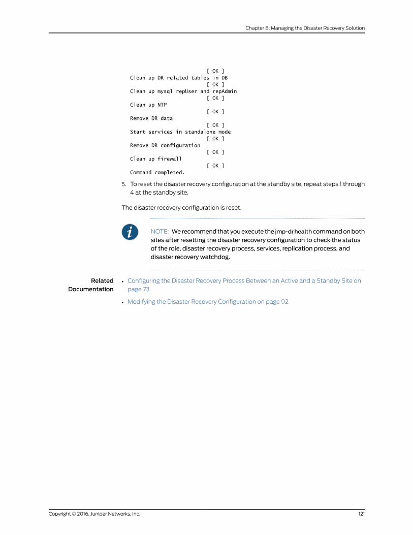
[ OK ]Clean up DR related tables in DB [ OK ]Clean up mysql repUser and repAdmin [ OK ]Clean up NTP [ OK ]Remove DR data [ OK ]Start services in standalone mode [ OK ]Remove DR configuration [ OK ]Clean up firewall [ OK ]Command completed.
5. To reset the disaster recovery configuration at the standby site, repeat steps 1 through
4 at the standby site.
The disaster recovery configuration is reset.
NOTE: Werecommendthat youexecute the jmp-drhealthcommandonboth
sites after resetting the disaster recovery configuration to check the statusof the role, disaster recovery process, services, replication process, anddisaster recovery watchdog.
RelatedDocumentation
• Configuring the Disaster Recovery Process Between an Active and a Standby Site on
page 73
• Modifying the Disaster Recovery Configuration on page 92
121Copyright © 2016, Juniper Networks, Inc.
Chapter 8: Managing the Disaster Recovery Solution

Copyright © 2016, Juniper Networks, Inc.122
High Availability and Disaster Recovery Guide

PART 3
Index
• Index on page 125
123Copyright © 2016, Juniper Networks, Inc.

Copyright © 2016, Juniper Networks, Inc.124
High Availability and Disaster Recovery Guide
Index
Symbols#, comments in configuration statements...................xiii
( ), in syntax descriptions.....................................................xiii
< >, in syntax descriptions...................................................xiii
[ ], in configuration statements.........................................xiii
{ }, in configuration statements........................................xiii
| (pipe), in syntax descriptions..........................................xiii
AApache load balancer
overview.............................................................................16
Bbraces, in configuration statements................................xiii
brackets
angle, in syntax descriptions......................................xiii
square, in configuration statements.......................xiii
Ccluster See Junos Space cluster
comments, in configuration statements.......................xiii
connection See DMI connection
conventions
text and syntax.................................................................xii
curly braces, in configuration statements.....................xiii
custom failure-detection script.........................................53
customer support...................................................................xiv
contacting JTAC..............................................................xiv
Ddevice arbitration algorithm................................................51
device-initiated connection.................................................22
disaster recovery
adding nodes.................................................................105
checking status................................................................91
checking the status.......................................................87
configuring the active site...........................................73
configuring the standby site.......................................73
manual failover to the standby site........................116
modifying applications..............................................105
operational scenario impacts...................................66
removing nodes............................................................105
starting ..............................................................................73
stopping............................................................................118
disaster recovery commands
jmp-dr api v1 config........................................................61
jmp-dr health....................................................................61
jmp-dr init..........................................................................61
jmp-dr manualFailover ................................................61
jmp-dr reset......................................................................61
jmp-dr start.......................................................................61
jmp-dr stop.......................................................................61
jmp-dr toolkit config update......................................61
disaster recovery configuration
modifying..........................................................................92
modifying failure-detection settings.....................101
modifying file backup settings................................102
modifying file restoration settings.........................103
modifying heartbeat settings...................................98
modifying notification settings..............................100
modifying scp settings.................................................97
resetting............................................................................119
disaster recovery solution
connectivity requirements.........................................48
impact of switching from the active to standby
sites..................................................................................71
normal operation of the active and standby
sites................................................................................64
prerequisites....................................................................48
disaster recovery watchdog................................................49
disaster recovery watchdog services
arbitermonitor.................................................................50
configmonitor..................................................................50
filemonitor........................................................................50
heartbeat..........................................................................49
mysqlmonitor..................................................................50
notification........................................................................51
pgsqlmonitor...................................................................50
servicemonitor.................................................................51
DMI connection
device initiated................................................................22
Junos Space initiated....................................................22
load balancing...........................................................15, 22
documentation
comments on..................................................................xiii
125Copyright © 2016, Juniper Networks, Inc.
Ffailover
detection...........................................................................33
impact................................................................................33
recovery..............................................................................33
failover scenarios See Junos Space cluster
font conventions......................................................................xii
Hheartbeat service, on Junos Space cluster....................20
high availability
overview...............................................................................3
high availability (HA) nodes
overview..............................................................................21
high availability (HA) solution
for network monitoring................................................23
key components...............................................................4
IIP address takeover...............................................................20
JJBoss application server
overview..............................................................................17
Junos Space appliances
networking parameters...............................................29
ordering..............................................................................27
overview...............................................................................3
Junos Space cluster..................................................................4
configuring for high availability.................................27
database services............................................................9
deployment overview......................................................3
disaster recovery............................................................45
failover................................................................................20
failover scenarios
detection...................................................................33
impact........................................................................33
recovery.....................................................................33
heartbeat service...........................................................20
high availability
adding a second node.........................................30
adding additional nodes......................................31
configuring the first node...................................30
preparation..............................................................28
removing nodes......................................................31
high availability nodes...................................................21
inter-node communication.........................................10
load balancing...................................................................9
physical appliances
recommendations for virtualization
infrastructure......................................................28
services provided by JBoss servers............................8
virtual appliances
recommendations for virtualization
infrastructure......................................................27
virtual IP address...........................................................20
See also logical clusters
Junos Space disaster recovery
solution..............................................................................46
Junos Space software
architecture....................................................................7, 11
components
Apache HTTP Server............................................12
JBoss Application Server.....................................12
MySQL Enterprise Edition relational
database................................................................11
network monitoring...............................................12
services
Distributed Resource Manager..........................12
Node Management Agent .................................12
Watchdog .................................................................12
Junos Space software stack.................................................11
Lload balancing
architecture.........................................................................9
database architecture....................................................9
logical clusters
Apache load balancer...................................................16
JBoss application server...............................................17
MySQL server...................................................................18
virtual IP availability within a cluster.......................19
Mmanuals
comments on..................................................................xiii
MySQL server
overview.............................................................................18
Nnetwork monitoring
FMPM nodes....................................................................23
protecting against node failures...............................23
SNMP trap destination IP address on
devices...........................................................................25
Copyright © 2016, Juniper Networks, Inc.126
High Availability and Disaster Recovery Guide
Pparentheses, in syntax descriptions................................xiii
previous disaster recovery process
stopping.............................................................................82
Ssoftware See Junos Space software
Space-initiated connection.................................................22
support, technical See technical support
syntax conventions.................................................................xii
Ttechnical support
contacting JTAC..............................................................xiv
VVIP See virtual IP address
virtual IP address
availability..........................................................................19
on Junos Space cluster................................................20
Wwatchdog service......................................................................4
127Copyright © 2016, Juniper Networks, Inc.
Index

Copyright © 2016, Juniper Networks, Inc.128
High Availability and Disaster Recovery Guide