HELMKE High-Voltage Motors with Flameproof Enclosure · High-Voltage Motors with Flameproof...
44
HELMKE High-Voltage Motors with Flameproof Enclosure Ex d IIC T4 Gb Ex d e IIC T4 Gb English
Transcript of HELMKE High-Voltage Motors with Flameproof Enclosure · High-Voltage Motors with Flameproof...

HELMKE High-Voltage Motors with
Flameproof EnclosureEx d IIC T4 Gb
Ex d e IIC T4 Gb
English

HV_Broschüre_EN_Druck_150416_C_FAB.indd 2 19.04.16 09:03

Contents
1 General information 51.1 Standards and regulations ....................................................................................................................................... 51.2 Explosion protection in the hazard zones ................................................................................................................ 51.3 Motors product range ............................................................................................................................................. 11
2 Mechanical characteristics 132.1 Setup conditions .................................................................................................................................................... 132.2 Model for lowest temperatures with stationary heating .......................................................................................... 132.3 Material .................................................................................................................................................................. 142.4 Paint ....................................................................................................................................................................... 142.5 Shaft ends, balancing, vibrations, noise level and coupling ................................................................................... 142.6 Types ..................................................................................................................................................................... 152.7 Belt drive ................................................................................................................................................................ 162.8 Terminal boxes ...................................................................................................................................................... 16
3 Electrical characteristics 173.1 Conditions for rated operation ................................................................................................................................ 173.2 Tolerances ............................................................................................................................................................. 173.3 Insulation and heating ............................................................................................................................................ 183.4 Circuitry .................................................................................................................................................................. 183.5 Motor protection ..................................................................................................................................................... 183.6 Alternating current motors with cage rotors in operation on the frequency inverter ............................................... 20
4 Operating data 214.1 Overview ................................................................................................................................................................ 214.2 Bearings ................................................................................................................................................................. 224.3 Technical data of standard motors ......................................................................................................................... 254.4 Dimensions of motors with frame sizes 355–500 (standard design) ...................................................................... 28
5 Mechanical execution and variants 305.1 Standard machine design ...................................................................................................................................... 305.2 Terminal box versions ............................................................................................................................................ 325.3 Customized designs ............................................................................................................................................... 35
6 Spare parts 38
7 Notes 39
Changes reserved
Changes to the services, technical data, dimensions and weight specified in this list remain reserved. The illustrations are non-binding.


0BGeneral information 5
1 General information
1.1 Standards and regulations The motors comply with the relevant standards and regulations, in particular:
Electrical
IEC standard EN standard Contents
IEC 60034-1 EN 60034-1 Rotating electrical machines – Part 1: Rating and performance
IEC 60034-8 EN 60034-8 Rotating electrical machines – Part 8: Terminal markings and direction of rotation
IEC 60079-0 EN 60079-0 Explosive atmospheres – Part 0: Equipment – General requirements
IEC 60079-1 EN 60079-1 Explosive atmospheres – Part 1: Equipment protection by flameproof enclosures “d”
IEC 60079-7 EN 60079-1 Explosive atmospheres – Part 7: Equipment protection by increased safety “e”
IEC 60079-31 EN 60079-31 Explosive atmospheres – Part 31: Equipment dust ignition protection by enclosure “t”
Mechanical
IEC standard EN standard Contents
IEC 60072 EN 50347 Dimensions and output
IEC 60034-5 EN 60034-5 Rotating electrical machines – Part 5: Degrees of protection provided by integral design of rotating electrical machines (IP-Code) – Classification
IEC 60034-6 EN 60034-6 Rotating electrical machines – Part 6: Methods of cooling (IC-Code)
IEC 60034-7 EN 60034-7 Rotating electrical machines – Part 7: Classification of types of construction, mounting arrangements and terminal box position (IM-Code)
IEC 60034-9 EN 60034-9 Rotating electrical machines – Part 9: Noise limits
IEC 60034-14 EN 60034-14 Rotating electrical machines – Part 14: Mechanical vibration of certain machines with shaft heights 56 mm and higher – Measurement, evaluation and limits of vibration severity
1.2 Explosion protection in the hazard zones
Protection classes The use of electrical machines in areas with explosion hazard is permissible on certain conditions. The machines must be designed in such a way that the explosion risk is eliminated to the furthest extent possible. An explosion may occur under the following conditions:
there is an explosive atmosphere;
there is the risk of a spreading explosion;
there are sources of ignition.
The ignition protection classes Ex d and Ex d e prevent one of the three conditions if gas is present and make an explosion impossible.
The ignition protection class for gas, Ex d e, represents a combination of:
pressure-resistant enclosure “d” for the motor housing;
increased safety “e” for the terminal box.
Hazardous areas and zones Hazardous areas are places where an explosive atmosphere may form under certain conditions.
An explosive atmosphere consists of a mixture of air and gasses, steams, mists and flammable dusts, in which a fire spreads quickly upon ignition under normal air pressure (explosion).
The user is obligated to apply the classification of the hazardous areas under own responsibility and in accordance with the European Directive 1999/92/EC.

6 0BGeneral information
The international standards EN / IEC 60079-10-1 and 60079-10-2 provide the criteria for the classification of the hazardous areas based on the chemical properties, physical properties, and the quantity of materials used, as well as in dependence on the frequency and duration in time when an explosive mixture may form.
Zones with explosive gas atmosphere
If the hazard is due to the presence of gas, steams or mists of flammable materials, the European Directive 1999/92/EC provides for a classification into the following three areas:
Zone 0 − areas in which an explosive atmosphere is present permanently or for long periods. In this area, the installation of electrical machines requires double protection.
Zone 1 − areas in which it is likely that an explosive atmosphere can form under normal conditions. In this zone, explosion-protected electrical motors with pressure-resistant enclosure, overpressure enclosure, or such with increased safety may be installed if a certificate from an accredited institution in accordance with the ATEX Guideline is provided.
Zone 2 − areas in which an explosive atmosphere can form only in very rare cases and can remain there only for a short period. In this zone, non-sparking motors may also be set up besides motors with pressure-resistant enclosure, overpressure enclosure or motors with increased safety. The certificate from an accredited institution is not required.
Zones with flammable dust formation
If the hazard is due to the presence of ignitable, flammable dust, the European Directive 1999/92/EC provides for a classification into the following three zones:
Zone 20 − areas in which an explosive atmosphere is present permanently or for long periods. There are no motors installed in this zone.
Zone 21 − areas in which it is likely that an explosive atmosphere can form under normal conditions. In this zone, electrical motors may be installed if a certificate from an accredited institution in accordance with the ATEX Guideline is provided and if they are installed with protection class IP6x.
Zone 22 − areas in which an explosive atmosphere can form only in very rare cases and can remain there only for a short period. Depending on the kind of dust, protection class IP6x may also be required in Zone 22. The certificate from an accredited institution is not required.
Classification of hazard zones
Area of use with presence of GAS
Area of use with presence of FLAMMABLE DUSTS
Hazard class of the setup zone
Zone 0 Zone 20 Explosive atmosphere is present permanently
Zone 1 Zone 21 Explosive atmosphere is probably present
Zone 2 Zone 22 Explosive atmosphere is unlikely
0BGeneral information 7
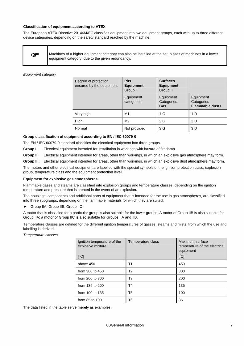
Classification of equipment according to ATEX The European ATEX Directive 2014/34/EC classifies equipment into two equipment groups, each with up to three different device categories, depending on the safety standard reached by the machine.
Machines of a higher equipment category can also be installed at the setup sites of machines in a lower equipment category, due to the given redundancy.
Equipment category
Degree of protection ensured by the equipment
Pits Equipment Group I
Surfaces Equipment Group II
Equipment categories
Equipment Categories Gas
Equipment Categories Flammable dusts
Very high M1 1 G 1 D
High M2 2 G 2 D
Normal Not provided 3 G 3 D
Group classification of equipment according to EN / IEC 60079-0 The EN / IEC 60079-0 standard classifies the electrical equipment into three groups. Group I: Electrical equipment intended for installation in workings with hazard of firedamp.
Group II: Electrical equipment intended for areas, other than workings, in which an explosive gas atmosphere may form.
Group III: Electrical equipment intended for areas, other than workings, in which an explosive dust atmosphere may form.
The motors and other electrical equipment are labelled with the special symbols of the ignition protection class, explosion group, temperature class and the equipment protection level.
Equipment for explosive gas atmospheres Flammable gases and steams are classified into explosion groups and temperature classes, depending on the ignition temperature and pressure that is created in the event of an explosion.
The housings, components and additional parts of equipment that is intended for the use in gas atmospheres, are classified into three subgroups, depending on the flammable materials for which they are suited:
Group IIA, Group IIB, Group IIC
A motor that is classified for a particular group is also suitable for the lower groups: A motor of Group IIB is also suitable for Group IIA; a motor of Group IIC is also suitable for Groups IIA and IIB.
Temperature classes are defined for the different ignition temperatures of gasses, steams and mists, from which the use and labelling is derived. Temperature classes
Ignition temperature of the explosive mixture [°C]
Temperature class Maximum surface temperature of the electrical equipment [°
above 450
C]
T1 450
from 300 to 450 T2 300
from 200 to 300 T3 200
from 135 to 200 T4 135
from 100 to 135 T5 100
from 85 to 100 T6 85
The data listed in the table serve merely as examples.

8 0BGeneral information
The equipment manufacturer is not responsible for the classification of the materials. The user is responsible for selecting the equipment (see EN / IEC 60079-14).
Classification of the most frequently occurring flammable materials, by explosion group and temperature class
Group Temperature class
T1 T2 T3 T4 T5 T6
I Methane (firedamp)
IIA Ammonia Ethane Ethyl acetate Acetone Benzol Butanone Methylene chlorine Chloroethylene Acetic acid Carbon monoxide Methane Methanol Methyl alcohol Methyl acetate Naphthalene Propane Toluene Xylene
Amyl alcohol Ethyl alcohol Butyl acetate Natural gas Acetic acid anhydride Liquid gas Isobutyl alcohol Monoamine acetate N-butyl alcohol Propyl acetate Cyclohexane
Decane Diesel fuel Crude oil* Heptane Hexane Kerosene Naphtha Pentane Cyclohexane Cyclohexene
Ether Acetaldehyde
IIB Coke gas Water gas
1.3-butadien Ethylene Ethyl benzene Ethylene oxide
Crude oil* Isoprene Hydrogen sulphide
Ethyl ether
IIC Hydrogen Acetylene Ethyl nitrate Carbon disulphide
* in the function of the chemical composition
Equipment for explosive dust atmospheres The housing of the devices with ignition protection class “t”, which are intended for the use in atmospheres with explosive dust, are classified into three subgroups depending on the kind of dust:
IIIA: flammable fibrous material
IIIB: non-conductive dust
IIIC: conductive dust
Group IIIC also requires at least protection class IP6x even if it is set up in Zone 22.
0BGeneral information 9
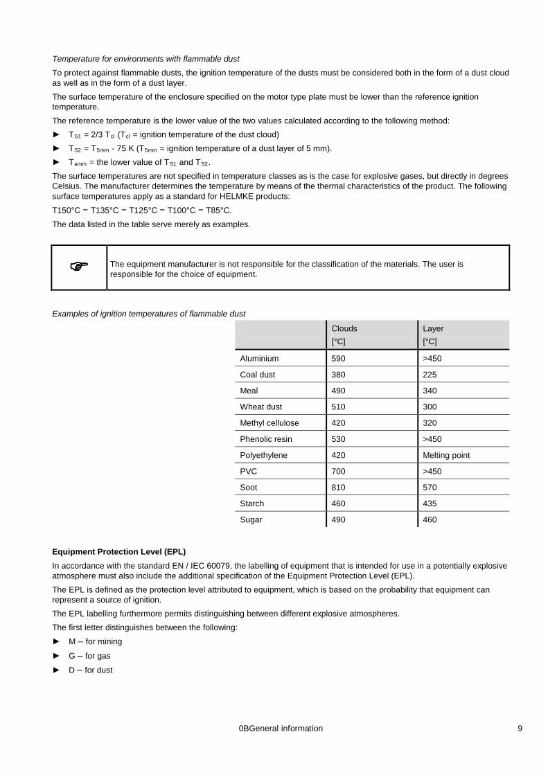
Temperature for environments with flammable dust
To protect against flammable dusts, the ignition temperature of the dusts must be considered both in the form of a dust cloud as well as in the form of a dust layer.
The surface temperature of the enclosure specified on the motor type plate must be lower than the reference ignition temperature.
The reference temperature is the lower value of the two values calculated according to the following method:
TS1 = 2/3 Tcl (Tcl
T
= ignition temperature of the dust cloud)
S2 = T5mm - 75 K (T5mm
T
= ignition temperature of a dust layer of 5 mm).
amm = the lower value of TS1 and TS2
The surface temperatures are not specified in temperature classes as is the case for explosive gases, but directly in degrees Celsius. The manufacturer determines the temperature by means of the thermal characteristics of the product. The following surface temperatures apply as a standard for HELMKE products:
.
T150°C − T135°C − T125°C − T100°C − T85°C.
The data listed in the table serve merely as examples.
The equipment manufacturer is not responsible for the classification of the materials. The user is responsible for the choice of equipment.
Examples of ignition temperatures of flammable dust
Clouds [°C]
Layer [°C]
Aluminium 590 >450
Coal dust 380 225
Meal 490 340
Wheat dust 510 300
Methyl cellulose 420 320
Phenolic resin 530 >450
Polyethylene 420 Melting point
PVC 700 >450
Soot 810 570
Starch 460 435
Sugar 490
460
Equipment Protection Level (EPL) In accordance with the standard EN / IEC 60079, the labelling of equipment that is intended for use in a potentially explosive atmosphere must also include the additional specification of the Equipment Protection Level (EPL).
The EPL is defined as the protection level attributed to equipment, which is based on the probability that equipment can represent a source of ignition.
The EPL labelling furthermore permits distinguishing between different explosive atmospheres.
The first letter distinguishes between the following:
M – for mining
G – for gas
D – for dust

10 0BGeneral information
The second letter indicates the probability that equipment can represent a source of ignition:
a - Equipment with “very high” protection level (guarantees safety in normal operations as well as in the case of predictable or rare errors/malfunctions);
b - Equipment with “high” protection level (guarantees safety in normal operations as well as in the case of predictable errors/malfunctions);
c - Equipment with “expanded” protection level (there is no hazard of ignition during normal operations; the device has a few additional protection features, which ensure that there is no hazard of ignition in the case of normally predictable failures).
Choice of the electrical explosion-protection The combination of hazard zones and the equipment categories to be used is defined by Directive 1999/92/EC. Notes on this topic are also provided in EN / IEC 60079-14.
The special construction standards for the protection classes (e. g. Ex d) also determine the motor category (e. g. 2 G) that is permissible for their use.
Examples for the choice of protection class for the ZONES with GAS atmosphere
Explosive atmosphere Hazard zone Protection ensured by the equipment Motor category Protection class
ALWAYS PRESENT 0 Very high 1 G See EN / IEC 60079-26
PROBABLE 1 High 2 G Ex d Ex d e Ex e Ex p
NOT PROBABLE 2 Normal 3 G Ex nA
Examples for the choice of protection class for areas with flammable dust
Explosive atmosphere Hazard zone Protection ensured by the equipment Motor category Protection class
ALWAYS PRESENT 20 Very high 1 D Ex ta
PROBABLE 21 High 2 D Ex tb
NOT PROBABLE 22 Conductive dust
Normal 3 D Ex tc IIIC
NOT PROBABLE 22 Non-conductive dust or fibrous material
Normal 3 D Ex tc IIIB Ex tc IIIA
Comment: Machines of a higher equipment category can also be installed at the setup places of machines in a lower equipment category.

0BGeneral information 11
1.3 Motors product range The motors described in this catalogue fulfil the requirements in accordance with the European Directive 2014/34/EC (ATEX Directive) regarding machines and protection equipment for the use in safe areas or in areas with a potential explosion hazard.
The user is responsible for the classification of the areas.
Temperature class
Type T3 T5 T6
355-500 Same output as T4 Same output as T4 Reduced output compared to T4
Basic characteristics Explosion-proof motors, which are protected against explosion according to the standards EN / IEC 60079-0, 60079-1,
60079-7 for gaseous environments. Asynchronous alternating current motors with cage rotors.
Asynchronous alternating current motors with cage rotors.
Completely enclosed, self-ventilated, housing IP55 with terminal box IP65.
The motors are air-cooled with external ventilation (standard EN / IEC 60034-6, Method IC411).
Axial or radial fan wheel dependend or independent of rotation direction.
Dimensions according to the standards EN 50347 / IEC 60072.
Power supply 6000 V / 50 Hz as standard. Alternating current motors, one rotation speed, 2-4-6 poles, T4 for design sizes from 355 mm to 500 mm, power supply with multi-range voltage and frequency upon by customer’s request.
Insulation class F.
Maximum sound pressure level 86 dB(A).
Terminal box: available both as flame proof “d” and increased safety “e” constructions, in enlarged design, pivotable by 90° in 4 positions.
Motor housing and terminal boxes are separated by design to avoid the spreading of explosions.
Type plate made of stainless steel, corrosion protected screws.
Strong impact resistance: motor housing, terminal boxes and bearing shields are steel welded constructions. ventilator and ventilator hub made of steel sheet.
The declaration of conformity is also available for special product characteristics that are different from the basic version, such as: operation above 1000 m absolute altitude, different voltages and frequencies, supply through frequency inverter, built-in temperature sensors in the motor, operating modes from S1 to S9.

12 0BGeneral information
Electrical design variants Special voltages and frequencies (max. voltage 6600 V).
Motors for tropical climatic zones.
Motors for low ambient temperatures (-50 °C).
Stator winding over temperature below 80 K.
Motors of insulation class F.
Motors with bi-metal contacts, PTC-thermistors or PT100 temperature sensors.
Motors with stationary heating.
Motors with electrical characteristics according to customer specifications.
Mechanical design variants Special flanges and shafts.
Second shaft end (NDE).
Terminal box with cable glands.
Terminal box with special wire inlets.
Motors without terminal box available with mountings for steel tubes for cable routing.
Motors with protection class IP56 – IP65 – IP66.
Motors with drainage valves for condensation water.
Motors with special bearings.
Vibration level of classes A or B, according to EN / IEC 60034-14.
Motors with rain or sunroof, water protection panel.
Slanted terminal box for increased safety “e” constructions
Separate terminal box for separated auxiliary terminals or additional accessory terminals.
Model with low sound emission.
Higher corrosion protection for tropical climate or applications in marine environments: exterior paint of mechanical components with epoxy varnish, protection of interior component (coil and rotor) with protective paint, rust-proof screws.
Accessories Motors for supply with electronic frequency inverter.
Motors with encoder.
Motors with external ventilation.

1BMechanical characteristics 13
2 Mechanical characteristics
2.1 Setup conditions The motors can be installed in clear and dusty, moist or chemically aggressive rooms (industry) with temperatures from -20 °C to +40 °C.
It is required to specify the respective setup conditions in the order.
Protection classes
First code number: Degrees of protection for protection against accidental contact and foreign matter
Second code number: Degree of protection for water protection
IP Declaration
0 No special protection
1 Protection against firm foreign matter larger than 50 mm (example: accidental contact with the hand)
2 Protection against firm foreign matter larger than 12 mm (example: accidental contact with the fingers)
3 Protection against firm foreign matter larger than 2.5 mm (examples: wires, tools)
4 Protection against firm foreign matter larger than 1 mm (examples: wires, tapes)
5 Protection against dust (harmful dust deposits)
6 Complete protection against dust
IP Declaration
0 No special protection
1 Protection against horizontally dripping water (condensation)
2 Protection against dripping water at inclinations up to 15°
3 Protection against spray water up to 60° from the vertical axis
4 Protection against splash water from all directions
5 Protection against water jets from a nozzle and from all directions
6 Protection against choppy seas or strong water jets
7 Protection when submerging between 0.15 and 1 m
8 Protection during long-lasting submersion in water under conditions agreed between the manufacturer and user.
2.2 Model for lowest temperatures with stationary heating Motors that are to be installed in regions with extremely low temperatures must be ordered separately.
The certificates on the explosion safety apply to temperatures up to -50 °C.
The motors equipped with heating elements (electrical resistor heating) maintain a minimum temperature of -20°C when the motor is at a standstill (see table).
During the operation of the motor, the heating elements must be switched off.
The standard voltage is 230 V ± 10 %.

14 1BMechanical characteristics
Stationary heating
Frame size For the prevention of condensation water
For use in environments with the temperatures below -20 °C (up to -50 °C)
Heating element Heating element Min. required power Min. required power [W] [W]
355M 200 400
355L 235 470
400M 250 500
400L 300 600
450 300 600
450L 350 700
500 385 770
500L 400 800
2.3 Material
Frame size 355–500
Motor housing, bearing shield, terminal box
Steel
Ventilator hood, rain protection roof
Steel
Fan wheel Steel
Shaft Steel C45
Rotor Copper cage
Coil Insulation class F
Screws, motor housing, bearing shield, terminal box
Steel 8.8 galvanized or A4-80 UNI EN ISO 3506-1
2.4 Paint
Frame size 355–500
Paint priming Components are sand-blasted, clean and free from grease, treated with rust-protection primer
Layer thickness, colour Top coat with enamel paint, overall 120 µm (other thicknesses on request) RAL 7030 (special colours on request)
Mechanical resistance Abrasion-resistant, elastic, scratch and impact-resistant
Corrosion resistance Excellent resistance against water, water steam and saline liquids
Chemical resistance, measurement conditions
Good resistance in chemically aggressive environment
2.5 Shaft ends, balancing, vibrations, noise level and coupling
Shaft ends The shaft ends are cylinder-shaped and comply with the standards EN 50347 / IEC 60072. As a standard, they are provided with a parallel key and a threaded hole on the front side for the mounting of belt pulleys and couplings.

1BMechanical characteristics 15
The parallel keys are included in the delivery of the motor. On request, motors with second shaft ends and/or special shaft end are also available.
Balancing, vibrations The rotors are dynamically balanced with a half parallel key according to ISO 8821.
The vibration values are within the limits prescribed by the standards EN / IEC 60034-14, Level “A” (N). For special requirements, motors with a vibration level of “B” (R) (reduced) are available.
It must be ensured before assembly that the transmission elements, such as belt pulleys and couplings have been dynamically balanced (full keyway and half key balancing).
Noise level The noise level values comply with the standards EN / IEC 60034-9. The nominal data include the sound pressure values “Lp” in dB (A) for each motor type.
These values apply to motors in idle run with a frequency of 50 Hz and a tolerance of +3 dB(A). For motors with 60 Hz, the sound pressure values are approx. 4 dB(A) higher than at 50 Hz.
Direct coupling For a direct coupling of the motor with the driven machine, the shaft axes have to be aligned properly in order to avoid damages or seizing up of the bearings.
The connection with a lamellar coupling or similar coupling types is permissible for all motors but in that case, as well, the axes have to be aligned properly. Special care is required in the assembly of 2-pole motors.
Belt drive In order to simplify assembly and the adjustment of the belt tension, assembly slides are commonly used on which the motor is mounted.
It has to be checked if the maximum radial stress generated by the belt tension is less than the maximum permissible force specified in the motor data. Belt pulleys and couplings may only be mounted and removed with the tools provided for this purpose.
2.6 Types The designs of the electrical machines are designated according to EN / IEC 60034-7, Code I (Bracket Value Code II).
Our motors can be delivered as specified in the table depending on the model and frame size.
IM B3 (IM 1001) IM V5 (IM 1011) IM V6 (IM 1031)
IM B5 (IM 3001) IM V1 (IM 3011) IM V3 (IM 3031)
IM B35 (IM 2001) IM V15 (IM 2011) IM V36 (IM 2031)
The required model has to be specified in the order, as the design will be adjusted in part to the installation position.

16 1BMechanical characteristics
2.7 Belt drive All data refer to the normal shaft end on the drive end side of motors of the model IM B3 with one rotation speed.
Calculation of the belt pull:
FR = radial axial force in N
P = output in kW
n = rotation speed in min-1
D1 = belt pulley diameter in m
k = pre-tension factor
The pre-tension factor depends on the belt type and it is assumed in approximation as follows:
3...4 for normal flat belts without tension roller 2...2.5 for normal flat belts with tension roller 2.2...2.5 for V-belts
The exact value has to be enquired from the belt manufacturer.
2.8 Terminal boxes Our series offers the following models:
Ex d IIC (Standard model)
Ex d e IIC
Ex d IIB
Ex d e IIB
Available on request:
Motors with additional terminal box for auxiliary cables
Motors without terminal box and conducted lines
Position of the terminal box and the terminals The terminal boxes are arranged in the upper area of the housing, the position of the cable inlets can be turned by 90° in four positions.
On horizontally mounted motors, the cable inlets are normally arranged on the right side (viewed from the drive side).
Terminals and protective conductor connection In the terminal box, maximally 3 power terminals can be arranged. The number of permissible accessory parts depends on the number of the terminals required for the motor and on whether an additional terminal box is provided.
Two additional terminals are required for PTC thermistors. Also, the connection of a stationary heating system requires two terminals.
For PT100 (RTD), 3 or 4 terminals are necessary depending on the chosen type.
The terminal box also contains one protective conductor terminal.
An additional protective conductor terminal is arranged on the motor housing.
Cable inlet thread The motors are delivered in the series standard with one or two cable inlets that are suitable for explosion-protected cable glands.
For Ex d e motors, also cable glands certified for the protection class Ex e can be used.
The motors equipped with temperature sensors or stationary heating have an additional cable inlet for the connection of these accessory parts. Cable inlet thread
Frame size Cable inlet thread
Ex d Ex e
355…500 1(2) x M63 x 1.5 1 x M75 x 1.5
N][nD
kP19120F1
R ⋅⋅⋅
=
2BElectrical characteristics 17
3 Electrical characteristics
3.1 Conditions for rated operation
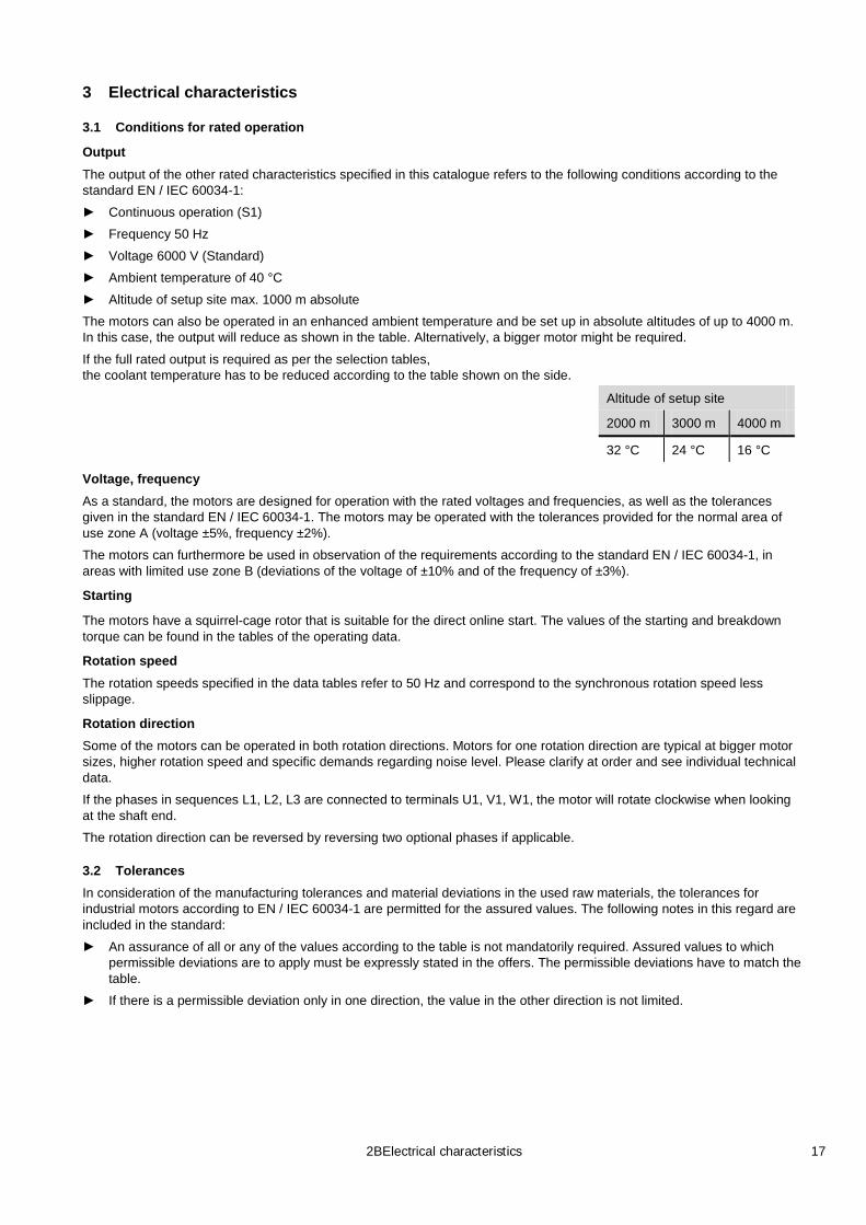
Output The output of the other rated characteristics specified in this catalogue refers to the following conditions according to the standard EN / IEC 60034-1:
Continuous operation (S1)
Frequency 50 Hz
Voltage 6000 V (Standard)
Ambient temperature of 40 °C
Altitude of setup site max. 1000 m absolute
The motors can also be operated in an enhanced ambient temperature and be set up in absolute altitudes of up to 4000 m. In this case, the output will reduce as shown in the table. Alternatively, a bigger motor might be required.
If the full rated output is required as per the selection tables, the coolant temperature has to be reduced according to the table shown on the side.
Altitude of setup site
2000 m 3000 m 4000 m
32 °C 24 °C 16 °C
Voltage, frequency As a standard, the motors are designed for operation with the rated voltages and frequencies, as well as the tolerances given in the standard EN / IEC 60034-1. The motors may be operated with the tolerances provided for the normal area of use zone A (voltage ±5%, frequency ±2%).
The motors can furthermore be used in observation of the requirements according to the standard EN / IEC 60034-1, in areas with limited use zone B (deviations of the voltage of ±10% and of the frequency of ±3%).
Starting
The motors have a squirrel-cage rotor that is suitable for the direct online start. The values of the starting and breakdown torque can be found in the tables of the operating data.
Rotation speed The rotation speeds specified in the data tables refer to 50 Hz and correspond to the synchronous rotation speed less slippage.
Rotation direction Some of the motors can be operated in both rotation directions. Motors for one rotation direction are typical at bigger motor sizes, higher rotation speed and specific demands regarding noise level. Please clarify at order and see individual technical data.
If the phases in sequences L1, L2, L3 are connected to terminals U1, V1, W1, the motor will rotate clockwise when looking at the shaft end.
The rotation direction can be reversed by reversing two optional phases if applicable.
3.2 Tolerances In consideration of the manufacturing tolerances and material deviations in the used raw materials, the tolerances for industrial motors according to EN / IEC 60034-1 are permitted for the assured values. The following notes in this regard are included in the standard:
An assurance of all or any of the values according to the table is not mandatorily required. Assured values to which permissible deviations are to apply must be expressly stated in the offers. The permissible deviations have to match the table.
If there is a permissible deviation only in one direction, the value in the other direction is not limited.

18 2BElectrical characteristics
Values for Tolerance
Efficiency class(η) (for indirect assessment)
-0.15 x (1−η) for PN ≤ 50 kW -0.10 x (1−η) for PN
Power factor (cos ϕ)
> 50 kW
6cos 1 ϕ−
− , at least 0.02, at most 0.07
Slippage (s) (for rated load in condition at operating temperature)
±20 % of the assured slippage for PN ≥ 1 kW ±30 % of the assured slippage for PN
Locked rotor current (I
< 1 kW
A +20 % of the assured locked rotor current without bottom limitation
) (in the intended start switching)
Locked rotor torque (MA -15 % and +25 % of the assured locked rotor torque (+25 % may be exceeded upon agreement)
)
Pull-up torque (MS -15 % of the assured value )
Tilting moment (MK -10 % of the assured value (after application of this tolerance, M
) K/MN
Inertia moment (J)
is at least 1.6)
±10 % of the assured value
3.3 Insulation and heating The insulation of the motors corresponds to thermal classes F according to EN / IEC 60034-1:
mica isolated copper wire
additional insulation materials on polyester or glass fiber basis
Vacuum pressure impregnation (VPI) with resin
The table shown on the side specifies the average heating (∆T) and maximum temperatures. The hottest points of the coil (Tmax
Class: ) according to the thermal classes of
the standard EN / IEC 60034-1.
∆T T
B
max
80 K 130 °C
F 105 K 155 °C
H 125 K 180 °C
3.4 Circuitry
Star circuit
The stator windings star point is internally connected.
Phase current and voltage are: Iph = IN; Uph = UN / 3
where IN is the rated current and UN is the rated mains voltage.
3.5 Motor protection The selection of a thermal protection for the motors should be made according to the given operating conditions. The motors can be protected through current-dependent motor circuit breakers or overcurrent relays and temperature sensors. Motor protection possible as follows:
Motor circuit breaker with bi-metal trigger
Thermistor protection with resistor temperature sensors (PTC) in the stator winding in connection with the triggering device (if applicable, additional motor circuit breaker)
Resistance thermometer for monitoring of the coil or bearing temperature PT100Ω
If a motor protection is required, bi-metal switches or resistor temperature sensors (PTC) can be installed.

2BElectrical characteristics 19
Mode of functioning of the bi-metal temperature sensors
Ti Switching temperature
Tr Reset temperature
Mode of functioning of the resistor temperature sensors (PTC type)
Ti Switching temperature
Type N/O (normally open) Type N/C (normally closed)
Circuitry examples
Protection measure Protection against...
Motor circuit breaker with thermal and electromagnetic overcurrent trigger
Overload in continuous operation
Blocked rotor
Not for operation with frequency converter according to EN / IEC 60079-14
Protection with overcurrent relay Thermistor protection and fuse
In operation, protection against:
Overload in continuous operation
Long start-up and braking processes
High switching frequency In case of failure, protection against: Obstruction of the cooling
Increased coolant temperature
One-phase run
Frequency fluctuations
Blocked rotor
Resistor temperature sensor with trigger device
In operation, protection against:
Overload in continuous operation
Long start-up and braking processes
High switching frequency In case of failure, protection against: Obstruction of the cooling
Increased coolant temperature
One-phase run
Frequency fluctuations
Blocked rotor
EN / IEC 60079-14 must be observed.

20 2BElectrical characteristics
3.6 Alternating current motors with cage rotors in operation on the frequency inverter The motors built specifically for this purpose, with ignition protection classes “d” or “d e”, can also be operated in classified areas with supply from an electronic frequency inverter. EN / IEC 60079-14 must be observed.
If Ex d motors with frequency inverters are used, the following factors must also be considered in addition to the common selection criteria:
Motors operated with frequency inverters do not have a pure sine-wave voltage (or current). This fact leads to rising dissipations, vibrations and noise level of the motor.
When using frequency inverters, the rotation speed of the motors can differ significantly from the rated rotation speed shown on the type plate. Rotation speeds exceeding the value shown on the type plate must be reconcilable with the motor and the motor-load-machine proposition.
The operating duration with a rotation speed higher than 3600 min-1
Maxim initial inverter voltage 6000 V with peak voltages of Û ≤ 12.2 kV and d/dt ≥ 1 µs
must not be above 10 % of the total work cycle of the motor in order to assure an appropriate lifetime.
-1
The motors non-drive bearing is insulated against shaft currents.
. For higher initial inverter voltages or loads, a special insulation is required.
An approved and functionally tested temperature monitoring device needed, that separate the motor from the supply in case of over-temperature.
Torque limits for operation with frequency inverter (IC411: self-ventilated; IC416: with external ventilation)
2-pole motors
Frame size 355
Frame sizes 400, 450, 500
4-, 6-pole motors
Frame size 355 Frame sizes 400, 450, 500

3BOperating data 21
4 Operating data The technical data specified in the following apply to the models with Ex d IIC/IIB and Ex d e IIC/IIB.
4.1 Overview
Type * Frame size Rated output [kW]
2-pole 4-pole 6-pole
DDOR355M 355 160 160 -
DDOR355M 355 200 200 -
DDOR355M 355 250 250 200
DDOR355L 355 315 315 250
DDOR355L 355 355 355 315
DDOR400M 400 400 400 -
DDOR400M 400 - 450 -
DDOR400L 400 450 500 355
DDOR400L 400 500 560 400
DDOR400L 400 - - 450
DDOR450M 450 560 - -
DDOR450L 450 630 630 500
DDOR450L 450 710 710 560
DDOR450L 450 - 800 630
DDOR500M 500 - 900 710
DDOR500M 500 800 1000 800
DDOR500L 500 900 1250 900
DDOR500L 500 1000 - 1000
* The type designations change depending on the ignition protection class as follows:
Ex d IIC: CDDOR
Ex d IIB: BDDOR
Ex d e IIC: CDEDOR
Ex d e IIB: BDEDOR

22 3BOperating data
4.2 Bearings
Bearing attribution (standard design) Grooved ball bearing and cylindrical roller bearings according to ISO 15 (DIN 625).
Frame size Number of poles
Drive side Non-drive side
355 2 (hor.) 6316 C3 6316 C3
2 (vert.) 6316 C3 7216 BM
355 4,6 (hor.) 6322 C3 6316 C3
4,6 (vert.) 6322 C3 7216 BM
400 2 (hor.) 6317 C3 6317 C3
2 (vert.) 6217 C3 7217 BM
400 4,6 (hor.) 6324 C3 6319 C3
4,6 (vert.) 6324 C3 7219 BM
450 2 (hor.) 6217 C3 + NU 217 C3 NU217 C3
2 (vert.) 6217 C3 7320 BM
450 4,6 (hor.) 6226 C3 + NU 324 C3 NU324 C3
4,6 (vert.) 6324 C3 7320 BM
500 2 (hor.) 6219 C3 + NU 219 C3 NU 219 C3
2 (vert.) 6219 C3 7322 BM
500 4 (hor.) 6228 C3 + NU 326 C3 NU 326 C3
4 (vert.) 6226 C3 7322 BM
500 6 (hor.) 6230 C3 + NU 328 C3 NU 328 C3
6 (vert.) 6228 C3 7322 BM
Standard design of bearings
(other arrangements on request) Frame size Bearing Drive side
Bearing on non-drive side
Spring element
355...500 Fixed bearing
Floating bearing
Non-drive side (hor.) Drive side(vert.)
The motor’s non-drive side bearing is insulated against shaft currents.

3BOperating data 23
Maximum permissible axial forces without additional radial forces
The values apply to 50 Hz and to minimum 50,000 hours assumed bearing life. For operation with 60 Hz, the values must be reduced by 10% (with effect from additional radial forces, a query is required depending on the direction of force). Horizontal shaft
Frame size Permissible axial forces (pressure or pull) [N]
Grooved ball bearing
3000 min 1500 min-1 1000 min-1
355
-1
4036 5650 7520
400 4973 8103 9767
450 7063 11575 13673
500 8842 16580 18365
Vertical shaft downward or upward
Frame size Permissible axial forces (pressure or pull) [N]
Angular contact ball bearings (downward)
Deep groove ball bearings (upward)
3000 min 1500 min-1 1000 min-1 3000 min-1 1500 min-1 1000 min-1
355
-1
4250 5312 5666 2825 3955 5264
400 4825 7750 8266 3481 5673 6836
450 10150 12687 13533 5504 8102 9571
500 12000 15000 16000 6188 11606 12855
Permissible radial forces
The values apply to 50 Hz and to minimum 50,000 hours assumed bearing life. For operation with 60 Hz, the values must be reduced by 6 % If the radial force is applied between points X0 and X2, the permissible force FR can be calculated from the following for-mula: FR = FX0 –X/E (FX0 – FX2
), where E = length of shaft extension in basic version.

24 3BOperating data
Frame size
Force impact point
Permissible radial forces [N]
Grooved ball bearing Cylinder roller bearing
3000 min-1 1500 min-1 1000 min-1 3000 min-1 1500 min-1 1000 min
355
-1
X 2830 0 8830 9490 − − −
X 1306 2 3210 3452 − − −
400 X 2530 0 8140 8580 − − −
X 1046 2 2960 3118 − − −
450 X - 0 - - 2940 6420 6870
X - 2 - - 1216 2334 2497
500 X - 0 - - 4170 36000 42750
X - 2 - - 1725 13109 15545
3BOperating data 25
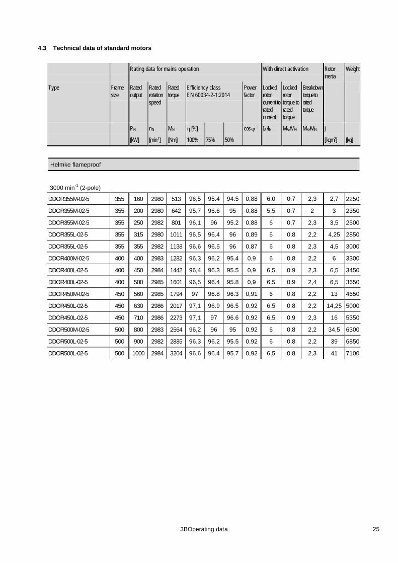
4.3 Technical data of standard motors
Rating data for mains operation With direct activation Rotor inertia
Weight
Type Frame size
Rated output
Rated rotation speed
Rated torque
Efficiency class EN 60034-2-1:2014
Power factor
Locked rotor current to rated current
Locked rotor torque to rated torque
Breakdown torque to rated torque
P nN MN η [%] N cos ϕ IA/I MN A/M MN K/M J N
[kW] [min-1 [Nm] ] 100% 75% 50% [ kgm2 [kg] ]
Helmke flameproof
3000 min-1 (2-pole)
DDOR355M-02-5 355 160 2980 513 96,5 95.4 94.5 0,88 6.0 0.7 2,3 2,7 2250
DDOR355M-02-5 355 200 2980 642 95,7 95.6 95 0,88 5,5 0.7 2 3 2350
DDOR355M-02-5 355 250 2982 801 96,1 96 95.2 0,88 6 0.7 2,3 3,5 2500
DDOR355L-02-5 355 315 2980 1011 96,5 96.4 96 0,89 6 0.8 2,2 4,25 2850
DDOR355L-02-5 355 355 2982 1138 96,6 96.5 96 0,87 6 0.8 2,3 4,5 3000
DDOR400M-02-5 400 400 2983 1282 96,3 96.2 95.4 0,9 6 0.8 2,2 6 3300
DDOR400L-02-5 400 450 2984 1442 96,4 96.3 95.5 0,9 6,5 0.9 2,3 6,5 3450
DDOR400L-02-5 400 500 2985 1601 96,5 96.4 95.8 0,9 6,5 0.9 2,4 6,5 3650
DDOR450M-02-5 450 560 2985 1794 97 96.8 96.3 0,91 6 0.8 2,2 13 4650
DDOR450L-02-5 450 630 2986 2017 97,1 96.9 96.5 0,92 6,5 0.8 2,2 14,25 5000
DDOR450L-02-5 450 710 2986 2273 97,1 97 96.6 0,92 6,5 0.9 2,3 16 5350
DDOR500M-02-5 500 800 2983 2564 96,2 96 95 0,92 6 0,8 2,2 34,5 6300
DDOR500L-02-5 500 900 2982 2885 96,3 96.2 95.5 0,92 6 0.8 2,2 39 6850
DDOR500L-02-5 500 1000 2984 3204 96,6 96.4 95.7 0,92 6,5 0.8 2,3 41 7100
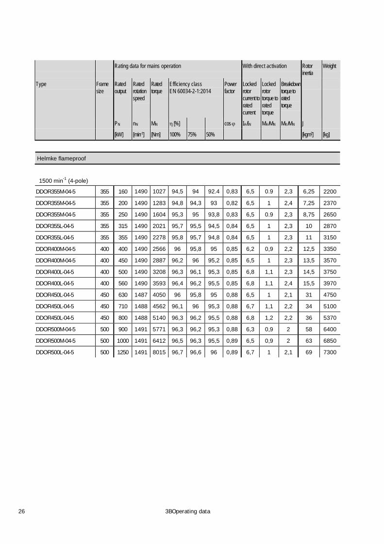
26 3BOperating data
Rating data for mains operation With direct activation Rotor inertia
Weight
Type Frame size
Rated output
Rated rotation speed
Rated torque
Efficiency class EN 60034-2-1:2014
Power factor
Locked rotor current to rated current
Locked rotor torque to rated torque
Breakdown torque to rated torque
P nN MN η [%] N cos ϕ IA/I MN A/M MN K/M J N
[kW] [min-1 [Nm] ] 100% 75% 50% [kgm2 [kg] ]
Helmke flameproof
1500 min-1 (4-pole)
DDOR355M-04-5 355 160 1490 1027 94,5 94 92.4 0,83 6,5 0.9 2,3 6,25 2200
DDOR355M-04-5 355 200 1490 1283 94,8 94,3 93 0,82 6,5 1 2,4 7,25 2370
DDOR355M-04-5 355 250 1490 1604 95,3 95 93,8 0,83 6,5 0.9 2,3 8,75 2650
DDOR355L-04-5 355 315 1490 2021 95,7 95,5 94,5 0,84 6,5 1 2,3 10 2870
DDOR355L-04-5 355 355 1490 2278 95,8 95,7 94,8 0,84 6,5 1 2,3 11 3150
DDOR400M-04-5 400 400 1490 2566 96 95,8 95 0,85 6,2 0,9 2,2 12,5 3350
DDOR400M-04-5 400 450 1490 2887 96,2 96 95,2 0,85 6,5 1 2,3 13,5 3570
DDOR400L-04-5 400 500 1490 3208 96,3 96,1 95,3 0,85 6,8 1,1 2,3 14,5 3750
DDOR400L-04-5 400 560 1490 3593 96,4 96,2 95,5 0,85 6,8 1,1 2,4 15,5 3970
DDOR450L-04-5 450 630 1487 4050 96 95,8 95 0,88 6,5 1 2,1 31 4750
DDOR450L-04-5 450 710 1488 4562 96,1 96 95,3 0,88 6,7 1,1 2,2 34 5100
DDOR450L-04-5 450 800 1488 5140 96,3 96,2 95,5 0,88 6,8 1,2 2,2 36 5370
DDOR500M-04-5 500 900 1491 5771 96,3 96,2 95,3 0,88 6,3 0,9 2 58 6400
DDOR500M-04-5 500 1000 1491 6412 96,5 96,3 95,5 0,89 6,5 0,9 2 63 6850
DDOR500L-04-5 500 1250 1491 8015 96,7 96,6 96 0,89 6,7 1 2,1 69 7300

3BOperating data 27
Rating data for mains operation With direct activation Rotor inertia
Weight
Type Frame size
Rated output
Rated rotation speed
Rated torque
Efficiency class EN 60034-2-1:2014
Power factor
Locked rotor current to rated current
Locked rotor torque to rated torque
Breakdown torque to rated torque
P nN MN η [%] N cos ϕ IA/I MN A/M MN K/M J N
[kW] [min-1 [Nm] ] 100% 75% 50% [kgm2 [kg] ]
Helmke flameproof
1000 min-1 (6-pole)
DDOR355M-06-5 355 200 991 1929 94,2 93,7 92,2 0,8 5,5 0,9 2 13,5 2800
DDOR355L-06-5 355 250 991 2412 94,6 94,2 92,8 0,8 5,5 0,9 2 16 3000
DDOR355L-06-5 355 315 991 3039 95 94,6 93,4 0,8 5,5 0,9 2 18 3300
DDOR400L-06-5 355 355 992 3421 94,8 94,6 93,3 0,8 5,3 0,8 2 26 3900
DDOR400L-06-5 400 400 992 3855 95 94,7 93,6 0,8 5,3 0,8 2 27 4150
DDOR400L-06-5 400 450 992 4337 95,3 95 93,8 0,8 5,5 0,8 2 28,5 4320
DDOR450L-06-5 400 500 992 4819 95,2 95 93,8 0,85 5,5 0,8 2 49 5250
DDOR450L-06-5 400 560 993 5391 95,4 95,1 94 0,85 6 0,9 2,2 52 5470
DDOR450L-06-5 450 630 993 6065 95,6 95,4 94,4 0,85 5,7 0,8 2 55 5750
DDOR50ML-06-5 450 710 994 6829 95,7 95,3 94,1 0,84 6,8 1 2,4 103 6500
DDOR500M-06-5 450 800 994 7694 96 95,8 94,5 0,85 6,8 1 2,4 111 6850
DDOR500L-06-5 500 900 994 8656 96,1 95,8 94,8 0,85 6,8 1 2,4 118,5 7200
DDOR500L-06-5 500 1000 994 9618 96,3 96 95 0,85 6,8 1,1 2,4 126,5 7550

28 3BOperating data
4.4 Dimensions of motors with frame sizes 355–500 (standard design) Model IM 1001 (B3)
Type
Frame size
Number of poles
Dimensions according to IEC [mm]
H A B C AB BB HD AC AD HA K L
Dimensions according to DIN [mm]
h b a w1 f e m1 g v c s k
DDOR355M-02-5 355 2 355 610 900 254 700 1250 1400 910 450 30 35 1950
DDOR355L-02-5 355 2 355 610 1120 254 700 1450 1400 910 450 30 35 2150
DDOR355M-04(6)-5 355 4-6 355 610 900 254 700 1250 1400 910 450 30 35 1950
DDOR355L-04(6)-5 355 4-6 355 610 1120 254 700 1450 1400 910 450 30 35 2150
DDOR400M-02-5 400 2 400 710 1120 280 840 1450 1460 930 450 30 35 2180
DDOR400L-02-5 400 2.. 400 710 1250 280 840 1600 1460 930 450 30 35 2330
DDOR400M-04(6)-5 400 4-6 400 710 1120 280 840 1450 1460 930 450 30 35 2180
DDOR400L-04(6)-5 400 4-6 400 710 1250 280 840 1600 1460 930 450 30 35 2330
DDOR450M-02-5 450 2. 450 800 112o 315 950 1450 1560 980 450 40 42 2340
DDOR450L-02-5 450 2 450 800 1250 315 950 1650 1560 980 450 40 42 2540
DDOR450M-04(6)-5 450 4-6 450 800 112o 315 950 1450 1560 980 450 40 42 2340
DDOR450L-04(6)-5 450 4-6 450 800 1250 315 950 1650 1560 980 450 40 42 2540
DDOR500M-02-5 500 2 500 850 1250 355 1020 1650 1670 1030 450 40 42 2540
DDOR500L-02-5 500 2 500 850 1400 355 1020 1750 1670 1030 450 40 42 2640 DDOR500M-04(6)-5 500 4-6 500 850 1250 355 1020 1650 1670 1030 450 40 42 2580 DDOR500L-04(6)-5 500 4-6 500 850 1400 355 1020 1750 1670 1030 450 40 42 2680

3BOperating data 29
Type
Frame size
Number of poles
Dimensions according to IEC [mm]
AA D E F GD GA
Dimensions according to DIN [mm]
n d l u t
DDOR355M-02-5 355 2 120 70 140 20 12 74.5
DDOR355L-02-5 355 2 120 70 140 20 12 74.5
DDOR355M-04(6)-5 355 4-6 120 100 210 28 16 106
DDOR355L-04(6)-5 355 4-6 120 100 210 28 16 106
DDOR400M-02-5 400 2 150 80 170 22 14 85
DDOR400L-02-5 400 2.. 150 80 170 22 14 85
DDOR400M-04(6)-5 400 4-6 150 110 210 28 16 116
DDOR400L-04(6)-5 400 4-6 150 110 210 28 16 116
DDOR450M-02-5 450 2. 225 80 170 22 14 85
DDOR450L-02-5 450 2 225 80 170 22 14 85
DDOR450M-04(6)-5 450 4-6 225 110 210 28 16 116
DDOR450L-04(6)-5 450 4-6 225 110 210 28 16 116
DDOR500M-02-5 500 2 225 90 170 25 14 95
DDOR500L-02-5 500 2 225 90 170 25 14 95 DDOR500M-04-5 500 4 225 120 210 28 16 127 DDOR500L-04-5 500 4 225 120 210 28 16 127 DDOR500M-06-5 500 6 225 130 250 32 18 137 DDOR500L-06-5 500 6 225 130 250 32 18 137

30 4BMechanical execution and variants
5 Mechanical execution and variants
5.1 Standard machine design Ex d – IC 411 – Cross section and 3D view

4BMechanical execution and variants 31
Ex d e – IC411 – Cross section and 3D view

32 4BMechanical execution and variants
5.2 Terminal box versions Main terminal box Ex d – Auxiliary terminal box Ex d
Main terminal box Ex d – Two auxiliary terminal boxes Ex d

4BMechanical execution and variants 33
Main terminal box Ex d – Auxiliary terminal box Ex e
Main terminal box Ex e – Auxiliary terminal box Ex e

34 4BMechanical execution and variants
Main terminal box Ex e – Auxiliary terminal box Ex e
Two main terminal boxes Ex e – Two auxiliary terminal boxes Ex e

4BMechanical execution and variants 35
5.3 Customized designs IM B3 – IC 416 – Variant with forced ventilation – Frame size 500
IM B3 – IC 411 – Variant with sleeve bearings and angular Ex d terminal boxes – Frame size 500

36 4BMechanical execution and variants
IM B3 – IC 511 – Variant with higher power rating – Frame size 710
IM B3 – IC 511 – Variant with higher power rating and reduced shaft height – Frame size (shaft height) 425

4BMechanical execution and variants 37
IM V1 – IC 411 – Variant for vertical application, flange and shaft at lower side – Frame size 560
IM V2 – IC 511 – Variant for vertical application, flange at lower side, shaft at upper side – Frame size 710

38 5BSpare parts
6 Spare parts
Nr. Designation Nr. Designation
1 Motor housing 14 External cover
2 Wounded stator 15 Shaft
3 Terminal box 16 Rotor
4 Terminal box cover 17 Bearing NDE
5 Auxiliary terminal box 18 End shield NDE
6 Auxiliary terminal box cover 19 External ring
7 Space heater terminal box 20 Safety washer
8 Space heater terminal box cover 21 Safety nut
9 Bearing DE 22 External cover
10 End shield DE 23 External fan
11 External ring 24 Fan hood
12 Safety washer 25 Bearing RTD
13 Safety nut

6BNotes 39
7 Notes

40 6BNotes

41 6BNotes


HV_Broschüre_EN_Druck_150416_C_FAB.indd 43 19.04.16 09:03

www.helmke.de