Hello, and welcome to this presentation of the single-wire ...
23
Hello, and welcome to this presentation of the single-wire protocol master interface or SWPMI. It covers the main features of this interface, which is used to connect a smartcard to the microcontroller. 1
Transcript of Hello, and welcome to this presentation of the single-wire ...

Hello, and welcome to this presentation of the single-wire protocol master interface or SWPMI. It covers the main features of this interface, which is used to connect a smartcard to the microcontroller.
1

The SWPMI integrated inside STM32 products implements a full-duplex single-wire communication interface, in compliance with the single-wire protocol defined in the ETSI TS 102 613 standard, in Master mode.The STM32 embeds the SWP transceiver. Applications benefit from the easy single pin connection to a smartcard for full-duplex communications up to 2 Mbit/s.
2

The SWPMI inside STM32 products offers three operating modes, with or without DMA, which are explained in detail later on. The STM32 supports both Class B and Class C supply operating voltages.
3
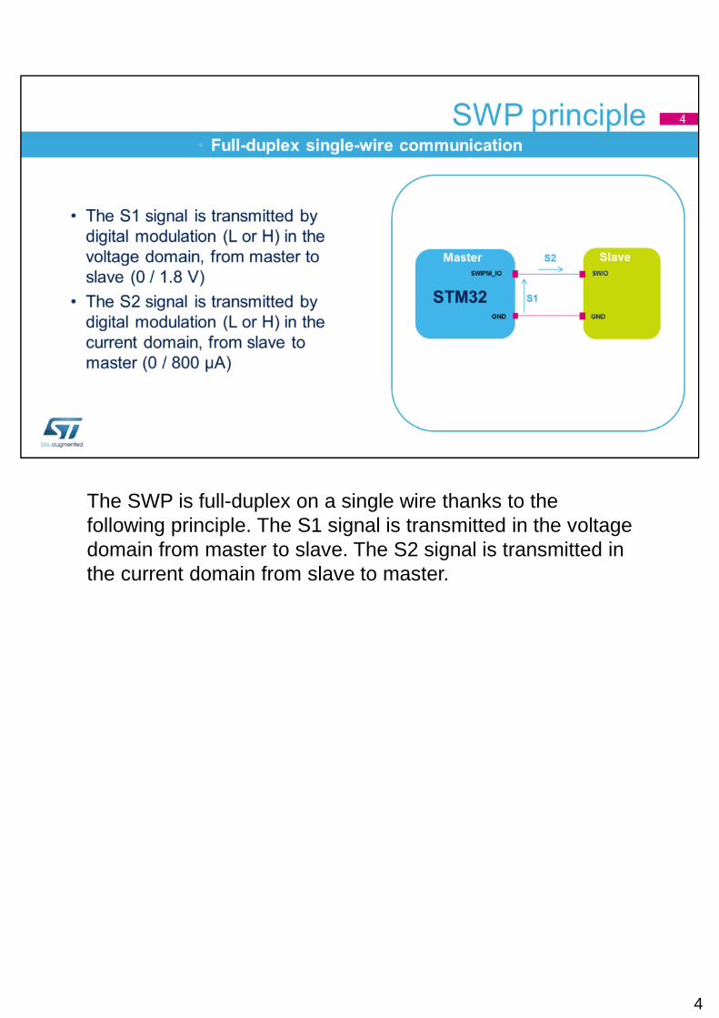
The SWP is full-duplex on a single wire thanks to the following principle. The S1 signal is transmitted in the voltage domain from master to slave. The S2 signal is transmitted in the current domain from slave to master.
4

The supply voltage or class must be selected in the STM32 during software initialization. A dedicated 1.8V voltage regulator inside the SWPMI_IO register is used to adjust the SWP voltage if VDD is 3V.
5

The S1 signal is transmitted by the STM32, the master, to the smartcard, the slave. A duty cycle of 25% on S1 codes a logical 0 (and an idle bit), while a duty cycle of 75% on S1 codes a logical 1. The S1 signal frequency determines the transmission clock.
6

The S2 signal is transmitted by the slave, the smartcard, to the master, the STM32. The slave draws a current while S1 is high to send a logical 1. If the slave does not draw any current while S1 is high, it is a logical 0.
7

SWP frames start with a Start of Frame field, coded by a 7E byte in hexadecimal format, and ends with an End of Frame field, coded by a 7F byte in hexadecimal format. The payload contains between 1 and 30 bytes of data. The protocol also implements bit stuffing. An extra-bit is inserted in case of 5 consecutive bits at 1. This guarantees that the Start and End of Frame fields are distinguished from the payload bytes. Data integrity is guaranteed by a 16-bit polynomial cyclic redundancy check (CRC).
8

The SWPMI automatically handles the Start and End of Frame fields, stuffing bits and the CRC. In this way, software just has to manage payload data.
9

Several states are defined for the SWP bus. In Deactivated state, the S1 signal is at low level. Before starting any communication, the master must raise the S1 signal to high level to set the SWP in Suspended state. Once communication is no longer required, the SWP can be deactivated by the master.
10

Now, either the master or the slave can initiate a communication, by sending a Resume sequence. A Resume sequence by the master consists of a transition sequence and 8 idle bits, whereas a Resume signal by the slave consists of drawing current until the master detects it and as a consequence starts to toggle the S1 signal to allow the slave to start transmitting data.
11

Here is an overview of how the SWP bus states are managed by the STM32. You can refer to the reference manual for more details about the initialization and activation procedures.
12
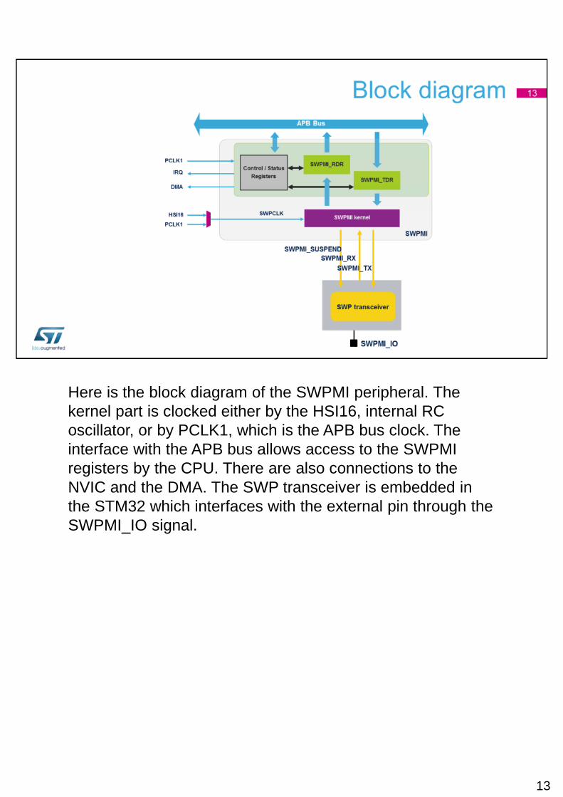
Here is the block diagram of the SWPMI peripheral. The kernel part is clocked either by the HSI16, internal RC oscillator, or by PCLK1, which is the APB bus clock. The interface with the APB bus allows access to the SWPMI registers by the CPU. There are also connections to the NVIC and the DMA. The SWP transceiver is embedded in the STM32 which interfaces with the external pin through the SWPMI_IO signal.
13

Here is the default configuration using the internal transceiver. The SWPMI_IO signal is available on the PB12 pin.
14

It’s also possible to connect an external transceiver using a configuration bit in the SWPMI registers. In this case, the Suspend, Receive and Transmit signals are available on pins PB15, PB14 and PB13. Pin PB12 can then be used as a standard GPIO.
15

Let’s look at the different operating modes, starting with No Software Buffer mode (NSB). In this mode, data is received and transmitted in Polling or Interrupt mode or by checking the SWPMI flags. Software intervention is required each time the Receive Data register becomes full or when the Transmit Data register becomes empty; that is to say, every 4 data bytes in the payload.
16

Software Single Buffer mode (SSB) is used to transmit or receive an entire SWP frame without software intervention. A 32-byte software buffer for frame transmission is defined in RAM, and the SWPMI automatically reloads the SWPMI_TDR register through the DMA until the End of Frame is received. For reception, a 32-byte software buffer is defined in RAM for frame reception, and the SWPMI_RDR register content is transferred to the RAM by the DMA. The first byte in the RAM buffer is used to code the number of bytes in the frame payload.
17

The last mode is Software Multi-Buffer mode (SMB). This mode also uses the DMA, and several SWP frames can be handled without software intervention. Let’s look at this example of a transmission, with 4 frame buffers in RAM. In this mode, 32 bytes are always reserved for each frame, regardless of the payload size. The DMA must be configured in Circular mode, and the number of words to be transferred must be set to 32. As in SSB mode, the first byte of each buffer is used to code the frame length (this is the TFL field). Software can read the DMA counter and update each frame buffer accordingly. In this example, three frames can be transmitted without software intervention. The transmission is stopped by disabling DMA Circular mode.In case you need to stop transmission before the DMA end of count, you must set the TFL field to 0. This way, the SWPMI will no longer issue any DMA requests.
18

In SMB mode, several frames can be received without software intervention. Let’s look at this example for reception, with four frame buffers in RAM. In this mode, the DMA must be configured in Circular mode, and the number of words to be transferred must be set to 32. The frame length is available at the end of each software buffer, in the 31th byte. The status of the frame stored in each software buffer is available in the 32nd byte which contains the error, overrun and buffer ready flags. This way, software can check the buffer ready flag, read the buffer and clear the 32nd byte.
19

Here is a summary of the events able to trigger an interrupt in the NVIC controller: Transmit and Receive buffers, Transmit and Receive registers, errors (CRC, overrun and underrun), and Resume by Slave.

DMA requests are generated by the SWPMI for transmission and reception. They must be enabled when working in SSB and SMB modes.

The peripheral is active in Run and Sleep modes. All SWPMI interrupts can wake up the device from Sleep mode. If the device is put in Stop mode, only a Resume by Slave event can wake up the device. In Standby mode, the peripheral is powered down and must be reinitialized after exiting Standby mode.
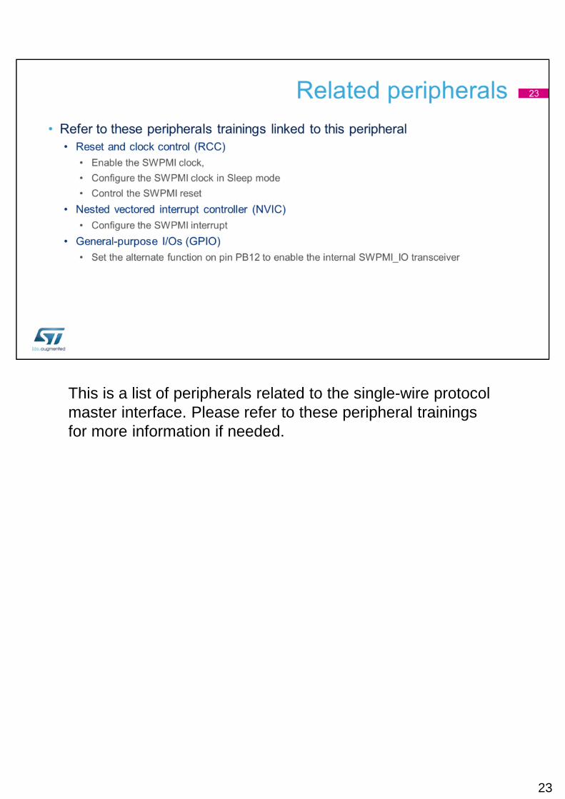
This is a list of peripherals related to the single-wire protocol master interface. Please refer to these peripheral trainings for more information if needed.
23