Heavy Duty Industrial Pressure Sensor - HyperCyl pressure switch... · Heavy Duty Industrial...
10
Heavy Duty Industrial Pressure Sensor For Hydraulic and Pneumatic Applications STEP FLUSH DIAPHRAGM Standard equipment Actual size GP - M Series RUGGED, VERSATILE, AND HIGHLY VISIBLE Easy to See Easy to Mount NEW Heavy Duty Digital Pressure Sensors GP-M Series
Transcript of Heavy Duty Industrial Pressure Sensor - HyperCyl pressure switch... · Heavy Duty Industrial...

Heavy Duty Industrial Pressure Sensor
For Hydraulic and Pneumatic Applications
STEP FLUSH DIAPHRAGM
Standard equipment
Actual size
GP-M Series
RUGGED, VERSATILE, AND HIGHLY VISIBLE
Easy to See Easy to Mount
NEW Heavy Duty Digital Pressure SensorsGP-M Series
5
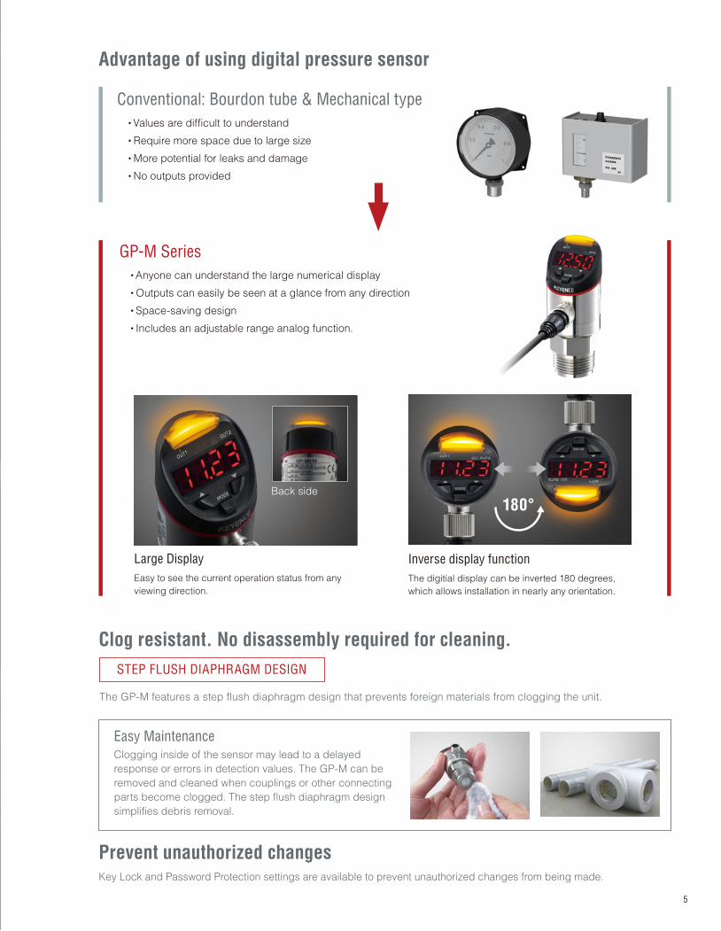
Clog resistant. No disassembly required for cleaning.
STEP FLUSH DIAPHRAGM DESIGN
The GP-M features a step flush diaphragm design that prevents foreign materials from clogging the unit.
Large Display
Easy to see the current operation status from any
viewing direction.
Back side
180°
Inverse display function
The digitial display can be inverted 180 degrees,
which allows installation in nearly any orientation.
Prevent unauthorized changesKey Lock and Password Protection settings are available to prevent unauthorized changes from being made.
Easy Maintenance
Clogging inside of the sensor may lead to a delayed
response or errors in detection values. The GP-M can be
removed and cleaned when couplings or other connecting
parts become clogged. The step flush diaphragm design
simplifies debris removal.
Conventional: Bourdon tube & Mechanical type
・Values are difficult to understand
・Require more space due to large size
・More potential for leaks and damage
・No outputs provided
GP-M Series
・Anyone can understand the large numerical display
・Outputs can easily be seen at a glance from any direction
・Space-saving design
・Includes an adjustable range analog function.
Advantage of using digital pressure sensor
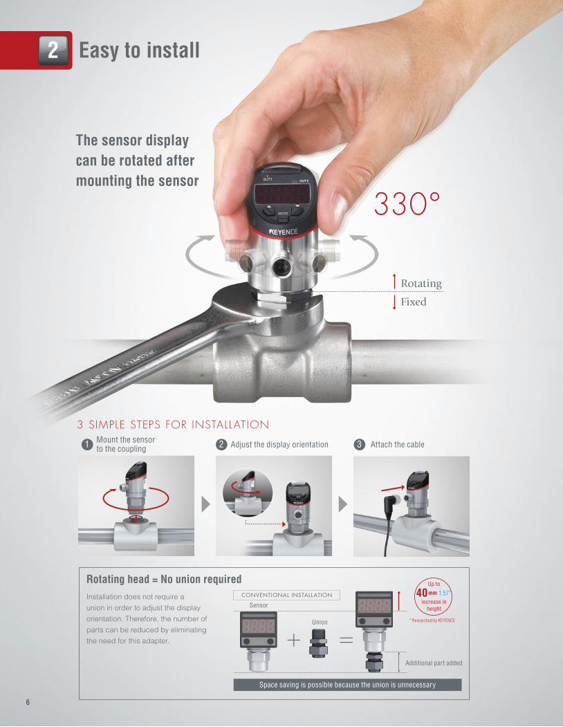
The sensor display
can be rotated after
mounting the sensor
330°
3 SIMPLE STEPS FOR INSTALLATION
Rotating
Mount the sensor to the coupling
1
CONVENTIONAL INSTALLATION
Sensor
Union
Additional part added
* Researched by KEYENCE
1.57"
Space saving is possible because the union is unnecessary
Up to
40mm
increase in
height
2 Easy to install
Fixed
Adjust the display orientation2 Attach the cable3
Installation does not require a
union in order to adjust the display
orientation. Therefore, the number of
parts can be reduced by eliminating
the need for this adapter.
Rotating head = No union required
6
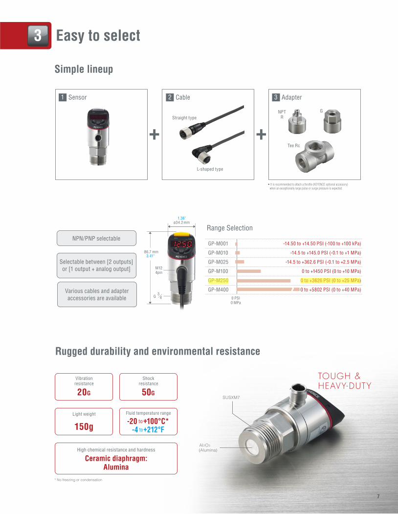
GP-M001 -14.50 to +14.50 PSI (-100 to +100 kPa)
GP-M010 -14.5 to +145.0 PSI (-0.1 to +1 MPa)
GP-M025 -14.5 to +362.6 PSI (-0.1 to +2.5 MPa)
GP-M100 0 to +1450 PSI (0 to +10 MPa)
GP-M250 0 to +3626 PSI (0 to +25 MPa)
GP-M400 0 to +5802 PSI (0 to +40 MPa)
Rugged durability and environmental resistance
1 2 3Sensor Cable Adapter
NPTR
Tee Rc
G
NPN/PNP selectable
Selectable between [2 outputs]
or [1 output + analog output]
Range Selection
0 PSI0 MPa
ø34.2 mm1.36"
3.41"86.7 mm
M124pin
G 43
SUSXM7
AI2O3
(Alumina)
TOUGH &HEAVY-DUTY
High chemical resistance and hardness
AluminaCeramic diaphragm:
Straight type
L-shaped type
• It is recommended to attach a throttle (KEYENCE optional accessory)
when an exceptionally large pulse or surge pressure is expected.
* No freezing or condensation
3 Easy to select
Simple lineup
Various cables and adapter
accessories are available
50G
Shockresistance
-20 to+100°C*-4 to+212°F
Fluid temperature range
20G
Vibrationresistance
150g
Light weight
7
mike.brieschke
Highlight
mike.brieschke
Highlight
SEL ECTAB LE FUNCT IONS ACCORD ING TO THE APP L ICAT ION
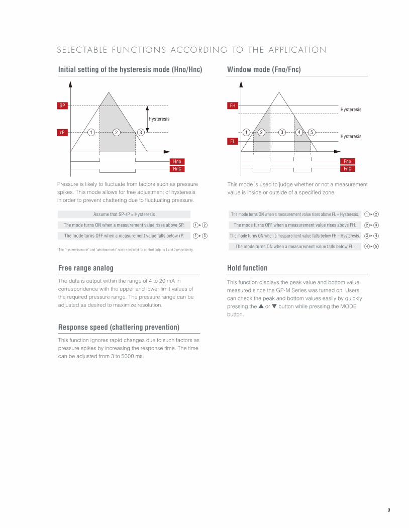
Initial setting of the hysteresis mode (Hno/Hnc)
2 3 4 51
FH
FL
Hysteresis
Fno
FnC
Hysteresis
1rP
SP
Hno
HnC
2 3
Free range analog Hold function
Window mode (Fno/Fnc)
Pressure is likely to fluctuate from factors such as pressure
spikes. This mode allows for free adjustment of hysteresis
in order to prevent chattering due to fluctuating pressure.
The data is output within the range of 4 to 20 mA in
correspondence with the upper and lower limit values of
the required pressure range. The pressure range can be
adjusted as desired to maximize resolution.
This function displays the peak value and bottom value
measured since the GP-M Series was turned on. Users
can check the peak and bottom values easily by quickly
pressing the ▲ or ▼ button while pressing the MODE
button.
This mode is used to judge whether or not a measurement
value is inside or outside of a specified zone.
Assume that SP-rP = Hysteresis
The mode turns ON when a measurement value rises above SP.
The mode turns ON when a measurement value rises above FL + Hysteresis.
The mode turns OFF when a measurement value rises above FH.
The mode turns ON when a measurement value falls below FH – Hysteresis.
The mode turns ON when a measurement value falls below FL.
The mode turns OFF when a measurement value falls below rP. 2 3
Hysteresis
* The “hysteresis mode” and “window mode” can be selected for control outputs 1 and 2 respectively.
1 2
1 2
2 3
3 4
4 5
Response speed (chattering prevention)
This function ignores rapid changes due to such factors as
pressure spikes by increasing the response time. The time
can be adjusted from 3 to 5000 ms.
9
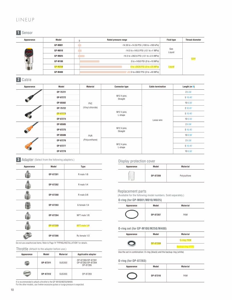
Appearance Model Material Connector type Cable termination Length (m ft)
OP-75721
PVC
(Vinyl chloride)
M12 4 pins
Straight
Loose wire
2 6.56'
OP-87272 5 16.40'
OP-85502 10 6.56'
OP-75722
M12 4 pins
L-shape
2 32.81'
OP-87273 5 16.40'
OP-87274 10 6.56'
OP-85505
PUR
(Polyurethane)
M12 4 pins
Straight
2 6.56'
OP-87275 5 16.40'
OP-85506 10 6.56'
OP-87276
M12 4 pins
L-shape
2 6.56'
OP-87277 5 16.40'
OP-87278 10 6.56'
Appearance Model Rated pressure range Fluid type Thread diameter
GP-M001 -14.50 to +14.50 PSI (-100 to +100 kPa)
Gas
Liquid
G3/4
GP-M010 -14.5 to +145.0 PSI (-0.1 to +1 MPa)
GP-M025 -14.5 to +362.6 PSI (-0.1 to +2.5 MPa)
GP-M100 0 to +1450 PSI (0 to +10 MPa)
LiquidGP-M250 0 to +3626 PSI (0 to +25 MPa)
GP-M400 0 to+5802 PSI (0 to +40 MPa)
Appearance Model Type
OP-87281 R male 1/8
OP-87282 R male 1/4
OP-87280 R male 3/8
OP-87283 G female 1/4
OP-87284 NPT male 1/8
OP-87285 NPT male 1/4
OP-87286 Rc female 1/2
Appearance Model Material
OP-87289 Polysulfone
Appearance Model Material
OP-87310 FKM
Appearance Model Material Applicable adapter
OP-87311 SUS303OP-87280/OP-87281OP-87282/OP-87284
OP-87285
OP-87312 SUS303 OP-87283
Appearance Model Material
OP-87287 FKM
Appearance Model Material
OP-87288
O-ring: FKM
Backup ring: PTFE
L I N E U P
Display protection cover
O-ring (for OP-87283)
Throttle (Attach to the adapter before use.)
O-ring (for GP-M001/M010/M025)
O-ring set (for GP-M100/M250/M400)
0
Use the set in combination: O-ring (black) and the backup ring (white)
It is recommended to attach a throttle to the GP-M100/M250/M400. For the other models, use it when excessive pulses or surge pressure is expected.
Do not use unauthorized items. Refer to Page 14 "PIPING/INSTALLATION" for details.
Replacement parts
(Available for the following model numbers. Sold separately.)
1 Sensor
2 Cable
3 Adapter (Select from the following adapters.)
10
mike.brieschke
Highlight
mike.brieschke
Highlight
mike.brieschke
Highlight
mike.brieschke
Highlight
mike.brieschke
Highlight
mike.brieschke
Highlight
mike.brieschke
Highlight
mike.brieschke
Highlight
skelly
Highlight
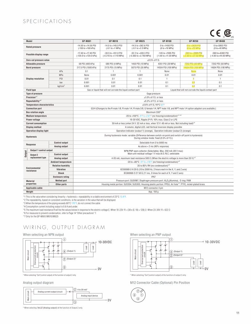
Model GP-M001 GP-M010 GP-M025 GP-M100 GP-M250 GP-M400
Rated pressure-14.50 to +14.50 PSI (-100 to +100 kPa)
-14.5 to +145.0 PSI (-0.1 to +1 MPa)
-14.5 to +362.6 PSI (-0.1 to +2.5 MPa)
0 to +1450 PSI (0 to +10 MPa)
0 to +3626 PSI (0 to +25 MPa)
0 to+5802 PSI(0 to+40 MPa)
Possible display range-17.40 to +17.40 PSI
(-120.0 to +120.0 kPa) -30.5 to +161.0 PSI
(-0.210 to +1.110 MPa)-52.2 to +400.3 PSI
(-0.360 to +2.760 MPa)-145 to +1595 PSI
(-1.00 to +11.00 MPa)-363 to +3989 PSI
(-2.50 to +27.50 MPa)-580 to+6382 PSI
(-4.00 to+44.00 MPa)
Zero-cut pressure value ±0.5% of F.S.
Allowable pressure 58 PSI (400 kPa) 580 PSI (4 MPa) 1450 PSI (10 MPa) 4351 PSI (30 MPa) 7252 PSI (50 MPa) 7252 PSI (50 MPa)
Burst pressure 217.5 PSI (1500 kPa) 2175 PSI (15 MPa) 5075 PSI (35 MPa) 14504 PSI (100 MPa) 14504 PSI (100 MPa) 14504 PSI (100 MPa)
Display resolution
kPa 0.1 1 1 None None None
MPa None 0.001 0.001 0.01 0.01 0.01
PSI 0.01 0.1 0.1 1 1 1
bar 0.001 0.01 0.01 0.1 0.1 0.1
kgf/cm2 0.001 0.01 0.01 0.1 0.1 0.1
Fluid type Gas or liquid that will not corrode the liquid contact part Liquid that will not corrode the liquid contact part
Type of pressure Gage pressure
Precision*1 ±1.0% of F.S. or less
Repeatability*2 ±0.3% of F.S. or less
Temperature characteristics ±0.6% of F.S./10°C 50°F
Connection port G3/4 (Changes to the R male 1/8, R male 1/4, R male 3/8, G female 1/4, NPT male 1/8, and NPT male 1/4 option adapters are available.)
Box rotation angle Maximum 330°
Medium temperature -20 to +100°C -4°F to +212°F (no freezing/condensation)*3 *6
Power voltage 10-30 VDC, Ripple (P-P): 10% max, Class 2 or LPS
Current consumption 50 mA or less (when 24 V: 32 mA or less, when 12 V: 48 mA or less. Not including load)*4
Display method 4 column, digital LED, red/Vertical inversion display possible
Operation display light Operation indicator (output 1) (orange), Operation indicator (output 2) (orange)
HysteresisDuring hysteresis mode: variable (Difference between switch-on point and switch-off point is hysteresis)
During window mode: fixed (0.5% of F.S.)
ResponseControl output Selectable from 3 to 5000 ms
Analog output As above + 2 ms (90% response)
Output 1 control output NPN/PNP open collector (Selectable), Max. 250 mA (30 V max)Main unit residual voltage 1 V max,N.O./N.C. selectable
Output 2 replacement type
Control output
Analog output 4-20 mA, maximum load resistance 500 Ω (When the electric voltage is more than 20 V)*5
Environmentalresistance
Ambient temperature -20 to +80°C -4°F to +176°F (no freezing/condensation)*6
Relative humidity 35 to 85% RH (no condensation)*6
Vibration IEC60068-2-6 20 G (10 to 2000 Hz, 2 hours each in the X, Y, and Z axis)
Shock IEC60068-2-27 50 G (11 ms, 3 times for each of X, Y and Z axis)
Enclosure rating IP67
Materialproperties
Wetted part Pressure port: SUSXM7, Diaphragm pressure port: Al2O3(Alumina), O ring: FKM
Other parts Housing metal portion: SUS304, SUS303, Housing plastic portion: PPSU, Air hole*7: PTFE, nickel-plated brass.
Applicable cable M12 connector 4 pin
Weight App. 150 g
S P E C I F I C AT I O N S
W I R I N G, O U T P U T D I A G R A MWhen selecting an NPN output
Analog output diagram
*1 This is the value when considering linearity + hysteresis + repeatability in a stable environment of 23°C 73.4°F.
*2 The repeatability, based on consistent conditions, is the variation in the value that will be displayed.
*3 When the temperature of the piping exceeds 80°C 176°F, do not connect the cable.
*4 Consumption current including output is 0.6 A and under.
*5 The maximum load resistance R will be the values below in response to the electric voltage E. When 10-23V: R = (38 x (E-10) + 128) Ω When 23-30V: R = 622 Ω
*6 For measures to prevent condensation, refer to Page 14 "Other precautions" 7.
*7 Only for the GP-M001/M010/M025
* When selecting "Out"(control output) of the function of output 2 only.
* When selecting "AnLG"(Analog output) of the function of Output 2 only.
* When selecting "Out"(control output) of the function of output 2 only.
When selecting an PNP output
M12 Connector Cable (Optional) Pin Position
(Output 1)
(Output 2)*
0V
10-30VDC1
1
2
2
3
3
4
4
1
2
3
4
0V
10-30VDC
(Output 1)
(Output 2)*
2
30V
4 to 20 mA*Analog current output circuit
Analog input device
Mai
n c
ircu
it
Ove
rcu
rren
t p
rote
cti
on
circ
uit
Lo
ad
Lo
ad
Mai
n c
ircu
it
Lo
ad
Lo
ad
Mai
n c
ircu
it
Ove
rcu
rren
t p
rote
cti
on
circ
uit
11
Ou
tpu
t
mike.brieschke
Highlight
mike.brieschke
Highlight
mike.brieschke
Highlight
mike.brieschke
Highlight
mike.brieschke
Highlight
mike.brieschke
Highlight
mike.brieschke
Highlight
mike.brieschke
Highlight
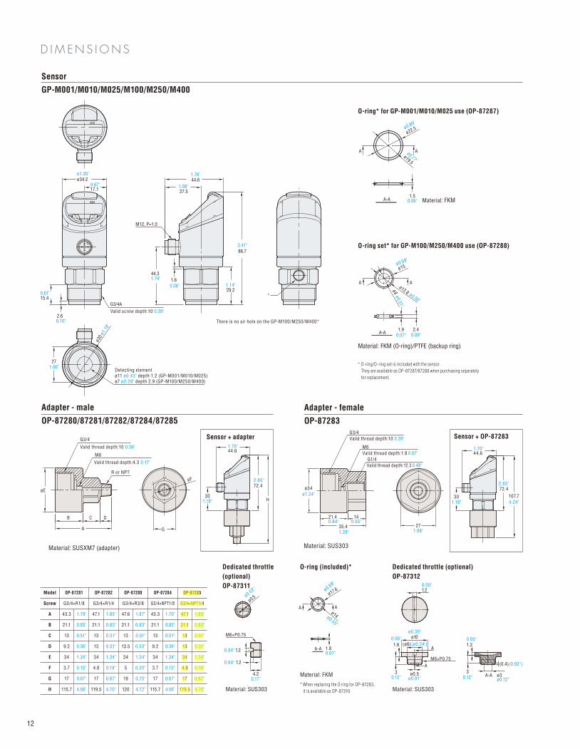
Sensor
GP-M001/M010/M025/M100/M250/M400
Adapter - male
OP-87280/87281/87282/87284/87285
Adapter - female
OP-87283
O-ring* for GP-M001/M010/M025 use (OP-87287)
O-ring set* for GP-M100/M250/M400 use (OP-87288)
ø19.5
ø0.77"
ø22.5ø0.89"
1.50.06"
A
A-A Material: FKM
A
Detecting element
ø11 ø0.43" depth 1.2 (GP-M001/M010/M025)
ø7 ø0.28" depth 2.9 (GP-M100/M250/M400)
ø30
ø1.1
8"
1.06"27
1.6
44.3
ø34.2ø1.35" 1.76"
1.08"17.10.67"
15.40.61"
0.10"2.6
Valid screw depth:10 0.39"
G3/4A
M12, P=1.0
86.7
*
44.6
27.5
29.21.14"0.06"
1.74"
ø12.8 ø0.50"
ø8
ø0.31"
ø15ø0.59"
Material: FKM (O-ring)/PTFE (backup ring)
* O-ring/O-ring set is included with the sensor.
They are available as OP-87287/87288 when purchasing separately
for replacement.
A-A
A
1.9 2.40.07" 0.09"
A
A
CB
øE
D
R or NPT
Valid thread depth:10
G3/4
Valid thread depth:4.3
M6
Material: SUSXM7 (adapter)
G
øF
Sensor + adapter
Material: FKM
* When replacing the O ring for OP-87283,
it is available as OP-87310. Material: SUS303Material: SUS303
Sensor + OP-87283
Valid thread depth:12.3
35.41.39" 1.06"
1421.40.55"0.84"
Valid thread depth:10
G3/4
ø34
ø1.34"
Valid thread depth:1.8
G1/4
M6
Material: SUS303
27
Dedicated throttle
(optional)
OP-87311
Dedicated throttle (optional)
OP-87312
72.42.85"
H
1.76"44.6
301.18"
107.7
4.24"
ø17.6
ø14ø0.55"
A-A
A
O-ring (included)*
1.80.07"
A
A
A
A-Aø0.5ø0.01"
ø3ø0.12"
(0.4)(0.02")
1.6
0.06"
1.2
30.12" 0.12"
3
M6×P0.75
M6×P0.75
1.20.04"
0.04"
0.17"
1.2
4.2
1.20.05"
0.05"
ø0.5ø0.0
2" ø0.69"
There is no air hole on the GP-M100/M250/M400*
(ø6)(ø0.24")
ø10ø0.39"
3.41"
0.39"
0.17"
0.39"
0.07"
0.48"
301.18"
1.76"44.6
72.42.85"
D I M E N S I O N S
12
Model OP-87281 OP-87282 OP-87280 OP-87284 OP-87285
Screw G3/4×R1/8 G3/4×R1/4 G3/4×R3/8 G3/4×NPT1/8 G3/4×NPT1/4
A 43.3 1.70" 47.1 1.85" 47.6 1.87" 43.3 1.70" 47.1 1.85"
B 21.1 0.83" 21.1 0.83" 21.1 0.83" 21.1 0.83" 21.1 0.83"
C 13 0.51" 13 0.51" 13 0.51" 13 0.51" 13 0.51"
D 9.2 0.36" 13 0.51" 13.5 0.53" 9.2 0.36" 13 0.51"
E 34 1.34" 34 1.34" 34 1.34" 34 1.34" 34 1.34"
F 3.7 0.15" 4.8 0.19" 5 0.20" 3.7 0.15" 4.8 0.19"
G 17 0.67" 17 0.67" 19 0.75" 17 0.67" 17 0.67"
H 115.7 4.56" 119.5 4.70" 120 4.72" 115.7 4.56" 119.5 4.70"
mike.brieschke
Highlight
mike.brieschke
Highlight
mike.brieschke
Highlight
mike.brieschke
Highlight
mike.brieschke
Highlight
mike.brieschke
Highlight
mike.brieschke
Highlight
mike.brieschke
Highlight
mike.brieschke
Highlight
mike.brieschke
Highlight
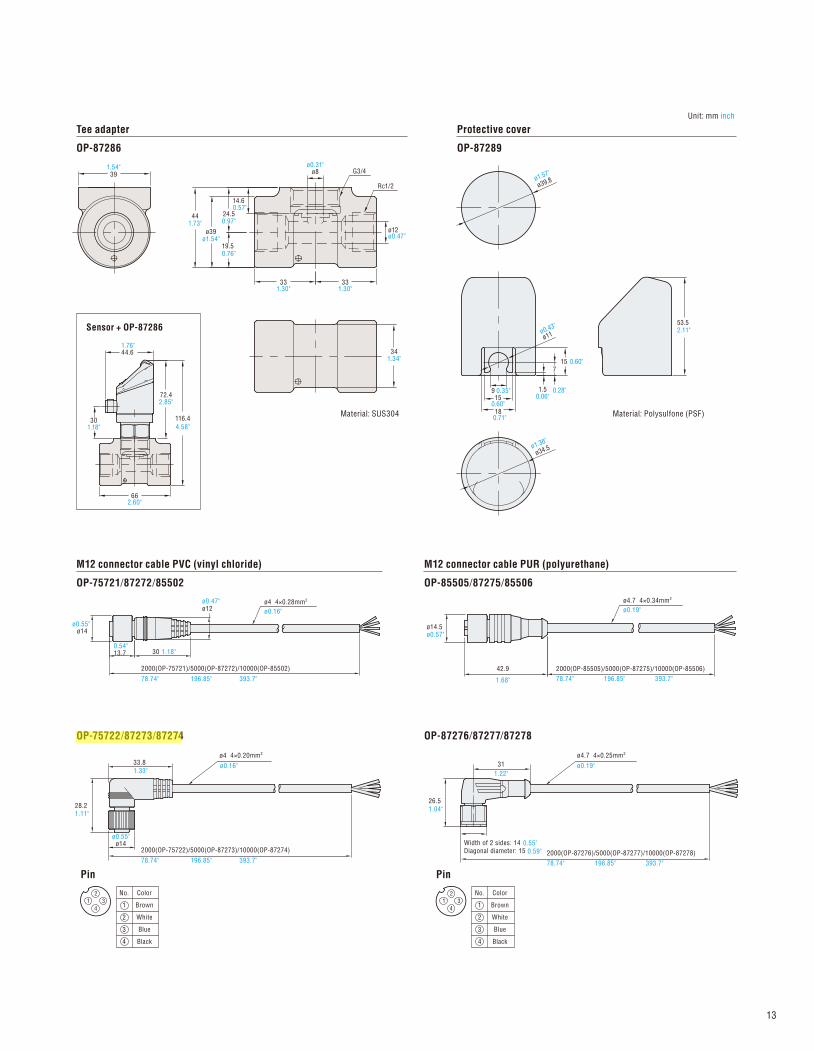
Tee adapter
OP-87286
Protective cover
OP-87289
M12 connector cable PVC (vinyl chloride)
OP-75721/87272/85502
M12 connector cable PUR (polyurethane)
OP-85505/87275/85506
OP-75722/87273/87274 OP-87276/87277/87278
341.34"
ø12ø0.47"
G3/4
33
441.73"
19.50.76"
ø39ø1.54"
331.30" 1.30"
391.54"
14.60.57"
24.50.97"
ø8ø0.31"
Material: SUS304
Rc1/2
Sensor + OP-87286
301.18"
116.4
4.58"
72.42.85"
662.60"
44.61.76"
ø4 4×0.28mm2 ø4.7 4×0.34mm2
ø14ø0.55"
ø12ø0.47"
ø0.16"
ø0.16"
13.70.54"
1.18"
78.74" 196.85" 393.7"
78.74" 196.85" 393.7"
30
2000(OP-75721)/5000(OP-87272)/10000(OP-85502)
Pin
4
3
2
No.
1
Black
White
Blue
Color
Brown3
4
1
2
42.9 2000(OP-85505)/5000(OP-87275)/10000(OP-85506)
ø14.5ø0.57"
2000(OP-75722)/5000(OP-87273)/10000(OP-87274)
ø4 4×0.20mm2
28.2
ø14
33.8
1.33"
26.5
1.04"
31
1.22"
0.55"
0.59"
Width of 2 sides: 14
Diagonal diameter: 15 2000(OP-87276)/5000(OP-87277)/10000(OP-87278)
ø4.7 4×0.25mm2
ø34.5ø1.36"
ø11ø0.43"
18
159 0.35" 1.5
0.06"
15 0.60"7
0.28"
ø39.8ø1.57"
53.52.11"
Material: Polysulfone (PSF)
Unit: mm inch
Pin
4
3
2
No.
1
Black
White
Blue
Color
Brown3
4
1
2
0.60"
0.71"
ø0.55"
1.11"
78.74"1.68" 196.85" 393.7"
78.74" 196.85" 393.7"
ø0.19"
ø0.19"
13
skelly
Highlight
SAFETY INFORM AT ION FOR GP-M SER IESGeneral precautions
Precautions when installing
Caution when handling
Other precautions
Attaching the coupling
Grounding of metal parts
Other precautions
Do not use this product for the purpose of protecting a human body or a part of human body.
This product is not intended for use as an explosion-proof product. Do not use this product in hazardous locations and/or potentially explosive atmospheres.
The GP-M Series is not designed to sanitary specifications. Do not use the product for applications such as drinks, foods, or medical liquids.
Do not use the GP-M Series for applications requiring safety
measures, such as any nuclear, railroad, aircraft, vehicle, or
playground equipment.
1.
2.
3.
4.
5.
6.
7.
The power ON reset time for the GP-M Series is 2 seconds after power is turned on. Do not use outputs from the sensor during this period.
Initial drift may occur after supplying power to the GP-M Series. To detect a minute difference in the pressure, let the GP-M Series warm up for approximately 15 to 30 minutes.
Do not bring a strong magnet or magnetic field close to the main body of the GP-M Series.
Do not remove the seal of the air hole of the GP-M001/M010/M025. It will no longer be waterproof.
When conducting maintenance, use a soft brush so as not to damage items such as the detection surface or the O ring.
When replacing the O ring, clean all of the debris from the surface that will be in contact with the O ring.
Condensation may cause measurement failure or breakage. To prevent this, take the following measures:• Make sure the ambient temperature is same as the fluid temperature or less.
• Use an A/C for dehumidification.• Keep the cooling pipe away from the sensor by 30 cm 11.81" or more using a connecting pipe.
The recommended ambient temperatures and relative humidities are within the highlighted area of the graph below.
The recommended tightening torque when installing the adapter to the main body of the sensor is
20 N•m. It is recommended to apply grease to the G3/4 threaded part in order to avoid thread damage.
• Regardless of whether the power of the device is ON or
OFF, do not touch the main part of the pressure detector. If the
pressure detector is touched, damage may occur due to static
electricity.
• If using a non-conductive liquid such as oil with plastic piping, the risk of an offset change
will become greater. In such a case, it is recommended to ground the metal housing.
• In the case that noise causes malfunction, grounding the metal housing may improve performance.
• After installation, conduct an atmospheric correction by making the applied pressure the same as
regular room pressure.
• When condensation occurs on piping, place the cooling pipe away form the sensor by 30 cm 11.81"
or more using a connecting pipe.
The metal parts of the main body and the internal circuits are 0 V insulated.
You must verify that the GP-M Series is operating correctly in terms of functionality and performance before the start and operation of the GP-M Series.
We recommend that you take all the necessary safety measures to avoid any damage in the unlikely event of a problem occurring.
Do not use the GP-M Series with corrosive liquids.
We cannot guarantee the functions and/or performance in the event that the product is used outside the standards of the specification, or if the product is modified.
When using our product in combination with another product, based on such factors as conditions of use and surrounding environment, sometimes functions and performance may not be fully realized. In such a case, use after adequate examination.
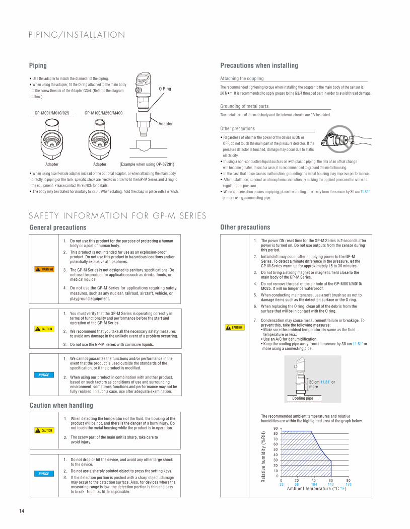
Piping
• Use the adapter to match the diameter of the piping.
• When using the adapter, fit the O ring attached to the main body
to the screw threads of the Adapter G3/4. (Refer to the diagram
below.)
• When using a self-made adapter instead of the optional adaptor, or when attaching the main body
directly to piping or the tank, specific steps are needed in order to fit the GP-M Series and O ring to
the equipment. Please contact KEYENCE for details.
• The body may be rotated horizontally to 330°. When rotating, hold the clasp in place with a wrench.
GP-M001/M010/025
Adapter
GP-M100/M250/M400
Adapter
O Ring
Adapter (Example when using OP-87281)
CAUTION
CAUTION
CAUTION
When detecting the temperature of the fluid, the housing of the product will be hot, and there is the danger of a burn injury. Do not touch the metal housing while the product is in operation.
The screw part of the main unit is sharp, take care to avoid injury.
Do not drop or hit the device, and avoid any other large shock to the device.
Do not use a sharply pointed object to press the setting keys.
If the detection portion is pushed with a sharp object, damage may occur to the detection surface. Also, for devices where the measuring range is low, the detection portion is thin and easy to break. Touch as little as possible.
1.
2.
3.
4.
1.
2.
3.
1.
2.
1.
2.
1.
2.
3.
Ambient temperature (°C °F)
Re
lati
ve h
um
idit
y (
%R
H)
032 68 104 140 176
0
10
20
30
40
50
60
70
80
90
20 40 60 80
30 cm 11.81" or more
Cooling pipe
WARNING
NOTICE
NOTICE
P I P ING/INSTAL L AT ION
14