Heavy Duty Cooling System Pressure Test & Refill Kit · Heavy Duty Cooling System Pressure Test &...
9
Heavy Duty Cooling System Pressure Test & Refill Kit Select and Assemble the Cap Adapter Before you can start the testing procedures, you need to select, assemble and connect the appropriate adapter for the vehicle you are testing. Warning! To avoid injury or damage, never remove a vehicle’s radiator cap or tester while the cooling system is under pressure. 1. Remove the cap from the vehicle’s filler neck and determine the style used (bayonet, external thread, internal thread). 2. Using the chart on the following pages, locate the cap adapter configuration that best matches the vehicle’s filler neck. When selecting, keep the following in mind: • To avoid cross threading and re-threading, never force an adapter onto a filler neck. If the adapter does not thread on smoothly, select another adapter. • Typically if the vehicle’s cap has a spindle, you will also need to use one with the adapter for proper sealing. IMPORTANT! Please make sure to carefully read all instructions, including the safety information at the back of this sheet before you begin testing. Kit Contents FJC Heavy Duty Cooling System Kits for Large Over-the-Road Trucks: FJC 43655 HD Cooling System Test Kit • Pressure Regulator • Vacuum Adaptor • Adapters #2, #12, #13, #14, #15 • Spindle A • Relief Hose • Storage Case Bayonet External Thread Internal Thread Part #43655 set screw handle Vacuum Refill Adaptor
Transcript of Heavy Duty Cooling System Pressure Test & Refill Kit · Heavy Duty Cooling System Pressure Test &...

Heavy Duty Cooling System Pressure Test & Refill Kit
Select and Assemble the Cap Adapter
Before you can start the testing procedures, you need to select, assemble and connect the appropriate adapter for the vehicle you are testing. Warning! To avoid injury or damage, never remove a vehicle’s radiator cap or tester while the cooling system is under pressure.
1. Remove the cap from the vehicle’s filler neck and determine the style used (bayonet, external thread, internal thread).
2. Using the chart on the following pages, locate the cap adapter configuration that best matches the vehicle’s filler neck. When selecting, keep the following in mind:
• Toavoidcrossthreadingandre-threading,never force an adapter onto a filler neck. If the adapter does not thread on smoothly, select another adapter.
• Typicallyifthevehicle’scaphasaspindle,youwillalsoneedtouseonewiththeadapterfor proper sealing.
IMPORTANT! Please make sure to carefully read all instructions, including the safety information at the back of this sheet before you begin testing.
Kit Contents
FJC Heavy Duty Cooling System Kits for Large Over-the-Road Trucks:
FJC 43655 HD Cooling System Test Kit•PressureRegulator•VacuumAdaptor•Adapters#2,#12,#13,#14,#15•SpindleA
•ReliefHose•StorageCase
Bayonet
ExternalThread
InternalThread
Part #43655
set screw
handle
Vacuum Refill Adaptor
Page2
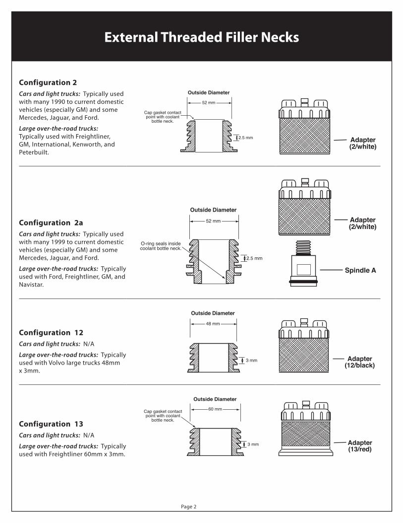
External Threaded Filler Necks
Configuration 2Cars and light trucks:Typicallyusedwith many 1990 to current domestic vehicles (especially GM) and some Mercedes, Jaguar, and Ford.
Large over-the-road trucks: TypicallyusedwithFreightliner,GM, International, Kenworth, and Peterbuilt.
Outside Diameter
52 mm
2.5 mm
Cap gasket contactpoint with coolant
bottle neck.
Adapter(2/white)
Configuration 2aCars and light trucks: Typicallyusedwith many 1999 to current domestic vehicles (especially GM) and some Mercedes, Jaguar, and Ford.
Large over-the-road trucks:Typicallyused with Ford, Freightliner, GM, and Navistar.
Outside Diameter
52 mm
2.5 mm
O-ring seals insidecoolant bottle neck.
Adapter(2/white)
Spindle A
Configuration 12Cars and light trucks: N/A
Large over-the-road trucks:TypicallyusedwithVolvolargetrucks48mmx3mm.
Outside Diameter
48 mm
3 mm Adapter(12/black)
Configuration 13Cars and light trucks: N/A
Large over-the-road trucks:TypicallyusedwithFreightliner60mmx3mm.
Outside Diameter
60 mm
3 mm
Cap gasket contactpoint with coolant
bottle neck.
Adapter(13/red)

Page3
External Threaded Filler Necks
Configuration 14Cars and light trucks: N/A
Large over-the-road trucks:TypicallyusedwithVolvotrucks63mmx3mm.
Outside Diameter
63 mm
3 mm
Cap gasket contactpoint with coolant
bottle neck.
Adapter(14/green)
Configuration 15Cars and light trucks: N/A
Large over-the-road trucks:Typicallyused with B size truck adapters.
Outside Diameter
48 mm
3 mm
Cap gasket contactpoint with coolant
bottle neck.
Adapter(15/yellow)

Page4
Before You BeginYou must attach a shop air quick disconnect fitting to the pressure regulator.
For the best test results
• Performthetestsintheorderlisted
• Whenusingshopair,90–125psiisrecommended
Step 1—Visually Inspect for Leaks / Damage
• Hoses,clampsandbelts • Sufficientairflow • Thermostathousing
• Radiator • Waterpump • Heatercore
• Coolantlevelandcondition • Watercontrolvalve • Cylinderhead/intakemanifold
If any of these conditions exist, repair or replace components as necessary before continuing.
Step 2—Check for Service CodesChecktheenginecontrolmoduleforanyservicecodes.Thesecodesmayverifyacoolingsystemrelatedsymptomandshouldbe serviced before testing.
Test Procedures
Adapter1
Filler Neck
Filler Neck
2
Adapter 1/Black1
Retainer A, B or C2
3
Step 3—Select and Assemble Cap AdapterUsing the reference chart, locate and assemble the appropriate cap adapter configuration for the vehicle.
Step 4—Connect to the Vehicle1. With the system cooled and the engine off, carefully remove the
pressure cap from the radiator or service tank.
2. Securelyattachthecapadapterassemblytotheradiatororfillerneck the same as you would the pressure cap.
3. Connectthepressureregulatortothecapadapterassemblyper the instructions for the particular test procedure you are performing.
To Disconnect From the Vehicle
1.VerifythattheballvalveisintheOFF position and then remove the shop air from the pressure regulator.
2.Connectoneendofthepressurerelief hose to the regulator airline adapter and the other end of the hose into a container (tocapturehotcoolant).TurntheballvalvetotheON position to relieve the system pressure from the previous test.
3. Oncethepressureisrelieved,removethepressurerelief hose and turn the ball valve to the OFF position.
4. Removeadapter(s)

Page5
Step 5—Pressure/Leak Test (Cold Engine)
Thistestrequiresthefollowingcomponents:
• Configuredcapadapterforthevehicleyouaretesting• PressureRegulator
Procedure:
Perform this test with the engine off.
1. Remove the vehicle’s radiator cap and connect the adapter assembly to the filler neck.
2.Connectthepressureregulatortothecapadapter.MakesuretheballvalveisintheOFF position
3.Connecttheshop’sairsupplytothePressureRegulatorviathequickdisconnect.
4. TurntheballvalvetotheON position (handle is parallel to the air hose).
5. Slowlyturnthecontroldialontheregulatoruntilthepressuregaugeisatthevehicle’sratedpressure.
Tip: Once the desired pressure is reached, you can lock the dial by pressing in the collar on the dial. Unlock the dial by pulling the collar out.
6. Inspectthecoolingsystemforanyexternalleaks.Thisincludesthefollowingareas:
• Hoses,Radiator,Watercontrolvalve • Heatercore
• Thermostathousing • Cylinderhead/intakemanifold
• Waterpump • Coolantrecovery/reservetank
Note: If any leaks are found, repair and retest before proceeding to the next step.
7. TurntheballvalvetotheOFF position and observe the pressure gauge readings.
• Ifthesystemmaintainsthepressure,proceedtothenexttest,Pressure Test—Warming Engine.
• Ifthesystemdoesnotholdthepressure,andthegaugereadingsbegintodrop,aleakispresent.
Checkforanyindicationofanexternalleak.Ifnoleakisfound,suspectaninternalleak(checkforcoolantintheoil).
Repair and retest before proceeding to the next step.
Step 6—Pressure Test (Warming Engine)
Thistestrequiresthefollowingcomponents:
• Configuredcapadapterforthevehicleyouaretesting• Pressurereliefhose• Pressureregulator
Start this test with the engine off and cold coolant.
1.VerifythattheballvalveisintheOFF position and then remove the shop air from the pressure regulator.
2.Connectoneendofthepressurerelief hose to the regulator airline adapter and the other end of the hose into a container(tocapturehotcoolant).TurntheballvalvetotheON position to relieve the system pressure from the previous test.
3. Oncethepressureisrelieved,removethepressurerelief hose and turn the ball valve to the OFF position.
4. Turnthepressurecontroldialclockwiseuntilitstops.
5. Startthevehicle’sengineandallowtoidle.
WarningTo avoid serious injury or damage while performing any of these tests, make sure you do the following:
• Donotpressurizethesystem(orallowthepressuretoincrease) beyond the radiator cap release pressure.
• Turntheengineoffimmediatelyifitbeginstooverheat.
• AlwaysmakesuretheballvalveisintheOFFpositionwhenever connecting or disconnecting the shop airline to theregulator.Failuretodosomayresultinreleasinghot/pressurizedcoolant.

Page6
6.Observethepressuregaugeastheenginewarmsup.
If the system is operating normally:• Thepressuregaugeincreasegraduallyastheenginewarmsup.
If the system is NOT operating normally:• Thepressurerisesrapidly.Thisisusuallycausedbycylindercompressionleakingintothecoolingsystemfroma
cracked cylinder head or gasket leak.
• Thepressurefluctuates.Thisisusuallycausedbyacrackbetweenthevalveseatsandheadgasket.
Ifthesystemisoperatingnormally,proceedtothenextstep.Otherwisemakeanynecessaryrepairsandretestbeforeproceeding.
Donotperformthisnextstepifthevehicle’sthermostatislocatedinthelowerhose.
7. Asthepressurerises,increasetheengineRPMtoapproximately2000whileobservingthepressuregauge.
If the system is operating normally:• ThepressurewilldropslightlyastheRPMsincrease.
If the system is NOT operating normally:• Ifthepressuredrops,suspectlowcoolantflowfromthewaterpump.
• Ifthepressureincreases,suspectapluggedradiator.
If the system is operating normally, proceed to the next test, Pressure/leak Test—Hot Engine.Otherwisemakeanynecessary repairs and retest before proceeding.
Step 7—Pressure/Leak Test (Hot Engine)
Thistestrequiresthefollowingcomponents:
• Configuredcapadapterforthevehicleyouaretesting• Pressurereliefhose• Pressureregulator
Procedure:
Perform this test with the engine off but with the coolant and engine hot.
USE EXTREME CAUTION—coolant is hot and can cause serious injury.
1.Connecttheshop’sairsupplytothepressureregulatorviathequickdisconnect.
2. TurntheballvalvetotheON position (handle is parallel to the air hose).
4. Slowlyturnthecontroldialontheregulatoruntilthepressuregaugeisatthevehicle’sratedpressure.
5. Inspectthecoolingsystemforanyexternalleaks.Thisincludesthefollowingareas:
• Hoses • Waterpump
• Radiator • Heatercore
• Watercontrolvalve • Cylinderhead/intakemanifold
• Thermostathousing • Coolantrecovery/reservetank
Note: If any leaks are found, repair and retest before proceeding to the next step.
6. TurntheballvalvetotheOFF position and observe the pressure gauge readings.
• Ifthesystemmaintainsthepressure,aleakisnotpresent.The test is complete.
• Ifthesystemdoesnotholdthepressure,andthegaugereadingsbegintodrop,aleakispresent.
Checkforanyindicationofanexternalleak.Ifnoleakisfound,suspectaninternalleak(checkforcoolantintheoil).Repair and retest.

Page7
UsetheVacuumRefillAdaptertoreplacecoolanttoanemptysystemaftertesting.Normalfill-timeisreducedbecausetheVacuumRefillAdapterremovesmostairpocketsandeliminatestheneedtobleedthesystemafterfilling. Before you begin, make sure that all repairs have been completed and no leaks are detected.
Thisprocedurerequiresthefollowingcomponents:
• Configuredcapadapterforthevehicleyouaretesting
• VacuumRefillAdapter
• Fillhose
Procedure:
Performthisprocedurewiththeenginecoldandoff,andthevehicle’stemperaturecontrolturnedtoHEAT.
1. Remove the vehicle’s radiator cap and connect the adapter assembly to the radiator or filler neck.
2.ConnecttheVacuumRefillAdaptertothecapadapter.
3.ConnectthefilltubetotheVacuumRefillAdapterandplacetheopenendofthetubeintothecoolant.Note: Make sure the coolant supply is at the same level, or higher, than the adapter.
4.Connecttheshop’sairsupplytothequickdisconnect.
5. SlidetheVacuumRefillAdapterhandletotheVACposition.Thisallows vacuum to build in the cooling system.
6.MonitorthegaugeontheVacuumRefillAdapter.Whenthevacuumstabilizes rapidly slide the handle to FILL to draw the coolant into the cooling system.
7.Continuefillingthesystemuntilthegaugeisat0”.
8.RemovetheVacuumRefillAdapterandcapadapter.
9. Make sure the system is filled to the proper levels (radiator and overflow tank).
10. Run the engine until it is at the normal operating temperature and the thermostat is open.
AdapterVacuumrefill adapter
Exhaustport
Slide to fillSlide to VAC
Quickdisconnect Fill hose
Radiator orfiller neck
Using the Vacuum Refill Adapter

Page8
Replacing the Vacuum Refill Adapter O-ringsAlwaysreplacetheO-ringswhenevertheybecomedamaged,deformed,dried,cracked,ormaybeleaking.
set screw
handle
correct
exhaustport
setscrew
incorrect
exhaustport
setscrew
To replace the inner O-rings:
1.Usingaphillipsscrewdriver,loosen(donotremove)theset-screw.
2. Slidetheadapter’shandleoffoftheadapterbody.
3.DiscardtheoldO-ringsandinstallthenewones.Makesuretoapplylubricant(includedintheO-ring/gasketkit)tothenewO-rings.
4.Placetheplasticstrip(includedintheO-ring/gasketkit)overbothO-rings.ThisprotectstheO-ringsfromdamagewhenslidingthehandle back on to the adapter.
5. Slidethehandlebackontotheadapterandpositionitsothatitiscentered across the adapter.
Note: Make sure the exhaust port is on the same side as the set screw. .
6. Tightenthesetscrew.
7. Firmly pull on the plastic strip to remove it from the adapter.

Page9
Safety Information
Before using this equipment, carefully read, understand and follow instructions and safety messages on equipment and in this guide.
Theguidecannotanticipateorprovideadviceandcautionsfor all situations encountered by technicians. With this in mind, always follow and refer to the manuals provided by the manufacturer or the vehicle or equipment being tested or used for all information and testing procedures whenever diagnosing, repairing or operating such vehicle or equipment.
Failure to follow the instructions, cautions and warnings provided here as well as those provided by the vehicle and equipment manufacturers can result in fire, explosion, bodily injury and property damage.
Vehicles emit flammable vapors which can ignite.
• Keepflames,sparks,cigarettesandotherignitionsourcesaway from the vehicle at all times.
• Incaseoffire,neverusewatertofightflamescausedbymethanolormethanolblendedgasoline.Thiswillcausetheflames to spread instead of extinguishing them.
• Useadrychemicalextinguishertofightflames(preferablyonemarkedABC,thoughBCisacceptable).AfoamextinguisherisacceptableonlyifitisARFgrade,whichisresistant to alcohol.
To avoid serious injury, do the following:• Usecautionwhentestingonavehiclewhiletheengineis
running (electric cooling fans may turn on unexpectedly eveniftheignitionisintheOFFposition,surfacesmaybecome hot, etc.)
• Removerings,watches,looseorhangingjewelry.Tielonghairsecurelybehindthehead.Takeextracarewithlooseorhanging clothing.
• Alwayswearapprovedsafetyglasseswhentesting.Shouldcoolant get into eyes, flush eyes immediately with water and consult your physician.
• Iftheskinisdirectlyexposed,washtheareaimmediatelyand change any clothes that have become wet with coolant.
• Neverremoveavehicle’sradiatorcaportesterwhilethecooling system is under pressure.
Before beginning any tests, make sure the test environment is safe and the vehicle meets these testing conditions:
• Testareashouldbewellventilated.
• Vehicleshouldbeinpark.
• Wheelsshouldbeblocked.
• Vehicleshouldhavenormalexhaustflow.
• Keepalltestercablesclearofexhaustmanifoldsandradiatorfan blades.
Warranty
FJCwarrantsthisradiatorpressuretesterfor1yearfromdateofpurchasewithproofofpurchase.Aswecannotcontroltheuseofourproducts,theguaranteeshallnotexceedthepurchaseprice.Wemakenootherwarrantyofanykindexpressedorimplied.Thisradiatorpressuretesteriswarrantedtobefreefromdefectsinmaterialandworkmanshipundernormaluseandservicefor1yearafterthesaleofthisproductbyFJC,Inc.FJC’ssoleobligationunderthiswarrantyshallbetorepairorreplaceanydefectiveproductorpartsthereof,whicharereturnedtoourfactory.Thewarrantyshallnotapplytoanyproductorpartwhichhasbeensubjecttomisuse,negligenceoraccident.FJC,Inc.shallnotberesponsibleforanyspecialorconsequentialdamagesandthewarrantyassetforthisinlieuofallotherwarrantieseitherexpressedorimplied.HoweverFJC,Inc.makesnowarrantyormerchantabilityinrespect to this item for any particular purpose other than that stated in this manual.
Safety Information & Warranty
www.fjcinc.com