TREND OF HEAT DEVELOPMENT OF PARALLEL AND TRANSVERSE WOOD PLACING IN OPEN FIREPLACE

WARNINGIF THE INFORMATION INTHESE INSTRUCTIONS ISNOT FOLLOWED EXACTLY, AFIRE OR EXPLOSION MAYRESULT CAUSING PROPERTYDAMAGE, PERSONAL INJURY,OR LOSS OF LIFE.
- Do not store or use gasoline or other flam-mable vapors and liquids in the vicinity of thisor any other appliance.
- What to do if you smell gas
• Do not try to light any appliance.
• Do not touch any electrical switch.
• Do not use any phone in your building.
• Immediately call your gas supplier from aneighbor's phone. Follow the gas supplier'sinstructions.
• If you cannot reach your gas supplier, call thefire department.
- Installation and service must be performed by aqualified installer, service agency, or the gassupplier.
Heat-N-Glo FireplaceModels:8000 DVTFL6000 DVTFL6000 XLT6000 ARCHSL-42 DVT
U.S. Patents 4,793,322; 4,875,464; 5,000,162 and Patents PendingCanadian Patent 1,297,746
Installers Guide
WARNING: IMPROPERINSTALLATION, ADJUSTMENT,ALTERATION, SERVICE ORMAINTENANCE CAN CAUSEINJURY OR PROPERTY DAMAGE.REFER TO THIS MANUAL. FORASSISTANCE OR ADDITIONALINFORMATION CONSULT AQUALIFIED INSTALLER, SERVICEAGENGY, OR THE GAS SUPPLIER.
Underwriters Laboratories Listed
484-980-B 7/97
READ THIS MANUAL BEFORE INSTALLING
OR OPERATING THIS APPLIANCE. THIS
INSTALLERS GUIDE MUST BE LEFT WITH
APPLIANCE FOR FUTURE REFERENCE.
1.This appliance may be installed in anaftermarket, permanently located,manufactured (mobile) home, wherenot prohibited by local codes.
2. This appliance is only for use with thetype of gas indicated on the ratingplate. This appliance is not convertiblefor use with other gases, unless acertified kit is used.
Please contact your Heat-N-Glo Fireplacedealer for any questions or concerns. For thenumber of your nearest Heat-N-Glo dealer,please call 612-890-8367.
Printed in U.S.A.
Copyright 1997,Heat-N-Glo Fireplace Products, Inc.6665 West Highway 13, Savage, MN 55378

i
SAFETY AND WARNING INFORMATION
READ and UNDERSTAND all instructions carefully before starting the installation.FAILURE TO FOLLOW these installation instructions may result in a possible firehazard and will void the warranty.
Prior to the first firing of the fireplace, READ the Using Your Fireplace section of theOwners Guide.
DO NOT USE this appliance if any part has been under water. Immediately CALL aqualified service technician to inspect the unit and to replace any part of the controlsystem and any gas control which has been underwater.
THIS UNIT IS NOT FOR USE WITH SOLID FUEL.
Installation and repair should be PERFORMED by a qualified service person. Theappliance and venting system should be INSPECTED before initial use and at leastannually by a professional service person. More frequent cleaning may be required dueto excessive lint from carpeting, bedding material, etc. It is IMPERATIVE that the unit�scontrol compartment, burners, and circulating air passageways BE KEPT CLEAN toprovide for adequate combustion and ventilation air.
Always KEEP the appliance clear and free from combustible materials, gasoline, andother flammable vapors and liquids.
NEVER OBSTRUCT the flow of combustion and ventilation air. Keep the front of theappliance CLEAR of all obstacles and materials for sevicing and proper operations.
Due to the high temperature, the appliance should be LOCATED out of traffic areas andaway from furniture and draperies. Clothing or flammable material SHOULD NOT BEPLACED on or near the appliance.
Children and adults should be ALERTED to the hazards of high surface temperature andshould STAY AWAY to avoid burns or clothing ignition. Young children should beCAREFULLY SUPERVISED when they are in the same room as the appliance.
These units MUST use one of the vent systems described in the Installing the Fireplacesection of the Installers Guide. NO OTHER vent systems or components MAY BE USED.
This gas fireplace and vent assembly MUST be vented directly to the outside and MUSTNEVER be attached to a chimney serving a separate solid fuel burning appliance. Eachgas appliance MUST USE a separate vent system. Common vent systems arePROHIBITED.
INSPECT the external vent cap on a regular basis to make sure that no debris isinterfering with the air flow.
The glass door assembly MUST be in place and sealed, and the trim door assemblyMUST be in place on the fireplace before the unit can be placed into safe operation.
DO NOT OPERATE this appliance with the glass door removed, cracked, or broken.Replacement of the glass door should be performed by a licensed or qualified serviceperson. DO NOT strike or slam the glass door.
The glass door assembly SHALL ONLY be replaced as a complete unit, as supplied bythe gas fireplace manufacturer. NO SUBSTITUTE material may be used.
DO NOT USE abrasive cleaners on the glass door assembly. DO NOT ATTEMPT toclean the glass door when it is hot.
Turn off the gas before servicing this appliance. It is recommended that a qualifiedservice technician perform an appliance check-up at the beginning of each heatingseason.
Any safety screen or guard removed for servicing must be replaced before operatingthis appliance.
LIMITED 10 YEAR WARRANTYHEAT-N-GLO GAS FIREPLACE PRODUCTS
In order to presumptively establish the dates to which your HEAT-N-GLO Limited 10 Year Warranty runs, youmust mail the completed warranty card to HEAT-N-GLO FIREPLACE PRODUCTS, INC., 6665 West
Highway 13, Savage, MN 55378, within 60 days of the date of fireplace installation. If you fail to do so, youmay be required to prove the date of installation before warranty work can be performed.
The warranty exclusions and limitations of liability are effective upon installation of the fireplace.
Subject to the conditions set forth herein, HEAT-N-GLO FIREPLACE PRODUCTS, INC. ("HEAT-N-GLO")extends the following warranty with respect to HEAT-N-GLO Gas Fireplace Products.
If HEAT-N-GLO is reasonably satisfied that any part or portion of the fireplace covered by this Limited Warrantyis defective in material or workmanship under normal use and service as described in the Owners Guide,HEAT-N-GLO will take the following actions:
1. If the defect is reported during the first year from the date of installation (stainless steel burners and fiber logsare covered for 3 years), HEAT-N-GLO will replace or repair the defective components at its sole expense. Thedecision whether to replace a component shall be made at HEAT-N-GLO's sole discretion. This LimitedWarranty does not cover components broken during shipping, misuse or careless handling. HEAT-N-GLOshall be not responsible for any indirect, incidental, or consequential damages or for any costs other than thoseincurred by HEAT-N-GLO to repair or replace the defective component. If components (including venting)other than factory approved components are used, all warranty and liability on the fireplace is voided. Defectsreported after the first year will not be covered by warranty unless they fall within the purview ofparagraph 2 or 3 below.
2. If the following defects are reported during the second year after the date of installation, HEAT-N-GLO willsupply replacement parts at the current wholesale price: defective electrical or manual components, optionalcomponents or accessories, and glass panels (not including glass panels broken during misuse or carelesshandling). HEAT-N-GLO shall not be responsible for any labor, transportation or other costs. Furthermore,HEAT-N-GLO shall not be liable for any indirect, incidental or consequential damages.
3. HEAT-N-GLO will replace or repair a defective firebox or heat exchanger, at any time during the 10 years fromthe date of installation. The decision whether to replace the defective component shall be made atHEAT-N-GLO's sole discretion. HEAT-N-GLO shall not be responsible for any indirect, incidental orconsequential damages or for any costs other than those incurred by HEAT-N-GLO to repair or replace thedefective component.
This Limited Warranty is the exclusive remedy available to you. If HEAT-N-GLO cannot effectively resolve awarranty problem in an expedient and cost-effective manner, it can discharge its entire warranty liability byrefunding the price of the product to you.
Products made by other manufacturers, whether sold with the fireplace or added thereafter, are NOT covered bythis Limited Warranty. The use of other unauthorized components will make this warranty null and void. ThisLimited Warranty will also be void if the appliance is not installed by a qualified installer in accordance with theInstallers Guide. Furthermore, the Limited Warranty will be void if the fireplace is not operated, at all times,according to the Owners Guide furnished with the fireplace. Any service work must be performed by authorizedservice representatives.
EXCEPT TO THE EXTENT PROVIDED BY LAW, NO OTHER EXPRESS OR IMPLIED WARRANTIES,INCLUDING WARRANTIES OF MERCHANTABILITY OR FITNESS FOR A PARTICULAR PURPOSE, SHALLAPPLY TO THE FIREPLACE PRODUCT. In States that do not allow limitations on how long an implied warrantylasts, or do not allow exclusion of indirect damages, those limitations or exclusions may not apply to you. You mayalso have additional rights not covered in this Limited Warranty.
HEAT-N-GLO reserves the right to make changes at any time, without notice, in design, material, specificationsand prices. It also reserves the right to discontinue styles and products.

ii
Table ofContents
Safety and Warning Information ................... i
Section 1: Approvals and Codes ................... 1Approval Listings and Codes ............................ 1
Appliance Certification .................................. 1Installation Codes .......................................... 1High Altitude Installations ............................ 1
Section 2: Getting Started ............................. 2Introducing the Heat-N-Glo Gas Fireplaces ...... 2Pre-installation Preparation ............................... 2
Section 3: Installing the Fireplace ................ 6Step 1 Locating the Fireplace .......................... 6Step 2 Framing the Fireplace .......................... 7Step 3 Installing the Vent System .................... 8
A. Vent System Approvals ............................. 8B. Installing Vent Components .................... 17C. Vent Termination ..................................... 23
Step 4 Positioning, Leveling, andSecuring the Fireplace ........................ 28
Step 5 The Gas Control Systems ................... 28Step 6 The Gas Supply Line .......................... 29Step 7 Gas Pressure Requirements ................ 30Step 8 Wiring the Fireplace ........................... 31Step 9 Finishing ............................................ 33Step 10 Installing Trim, Logs, and
Ember Material .................................. 34Installing the Trim ........................................ 34Positioning the Logs .................................... 35Placing the Ember Material .......................... 35
Step 11 Before Lighting the Fireplace ............ 37Step 12 Lighting the Fireplace ....................... 37After the Installation ........................................ 37
Section 4: Maintenance and Servicing ....... 38
Section 5: Replacement Partsand Accessories .......................... 40
Replacement Parts ........................................... 40Accessories ...................................................... 43

1
Approval Listingsand Codes
Appliance CertificationThe Heat-N-Glo fireplace models discussed in thisInstallers Guide have been tested to certificationstandards and listed by the applicable laboratories.
CERTIFICATIONMODEL LABORATORY TYPE STANDARD
8000DVTFL Underwriters Direct Vent ANSI Z21.50•CGA2.22Laboratories Decorative
6000DVTFL Underwriters Direct Vent ANSI Z21.50•CGA2.22Laboratories Decorative
6000ARCH Underwriters Direct Vent ANSI Z21.50•CGA2.22Laboratories Decorative
6000XLT Underwriters Direct VentLaboratories Decorative ANSI Z21.50•CGA2.22
Wall Furnace Z21.44/IR#41/CANI-2.19
SL-42DVT Underwriters Direct Vent ANSI Z21.50•CGA2.22Laboratories Decorative
Installation CodesThe fireplace installation must conform to local codes. Before installing thefireplace, consult the local building code agency to ensure that you are incompliance with all applicable codes, including permits and inspections.
In the absence of local codes, the fireplace installation must conform to theNational Fuel Gas Code ANSI Z223.1 (in the United States) or the CAN/CGA-B149 Installation Codes (in Canada). The appliance must be electricallygrounded in accordance with local codes or, in the absence of local codes withthe National Electric Code ANSI/NFPA No. 70 (in the United States), or to theCSA C22.1Canadian Electric Code (in Canada).
These models may be installed in a bedroom or bed-sitting room in the U.S.A.and Canada.
High Altitude InstallationsU.L. Listed gas fireplaces are tested and approved for elevations from 0 to 2,000feet in the U. S. A. and from 0 to 4,500 feet in Canada.
When installing this fireplace at an elevation above 2,000 feet (in the UnitedStates), it may be necessary to decrease the input rating by changing theexisting burner orifice to a smaller size. Input should be reduced four percent(4%) for each 1,000 feet above sea level, unless the heating value of the gas hasbeen reduced, in which case this general rule will not apply. To identify the properorifice size, check with the local gas utility.
When installing this fireplace at an elevation between 2,000 and 4,500 feet (inCanada), the input rating must be reduced by ten percent (10%).
When installing this fireplace at an elevation above 4,500 feet (in Canada), checkwith local authorities.
Consult your local gas utility for assistance in determining the proper orifice foryour location.
1Approvalsand Codes

2
Introducing theHeat-N-GloGas Fireplaces
Heat-N-Glo direct vent gas fireplaces are designed tooperate with all combustion air siphoned from outsideof the building and all exhaust gases expelled to theoutside.
The information contained in this Installers Guide,unless noted otherwise, applies to all models and gascontrol systems.
Gas fireplace diagrams, including the dimensions, areshown in this section.
Pre-installationPreparation
This gas fireplace and its components are tested andsafe when installed in accordance with this InstallersGuide. Report to your dealer any parts damaged inshipment, particularly the condition of the glass. Donot install any unit with damaged, incomplete, orsubstitute parts.
The vent system components and trim doors areshipped in separate packages. The gas logs arefactory installed (Model 8000DVTFL) and arepackaged separately and must be field installed(Models 6000DVTFL, 6000ARCH, 6000XLT, SL-42DVT). Read all of the instructions beforestarting the installation. Follow these instructionscarefully during the installation to ensuremaximum safety and benefit. Failure to followthese instructions will void the owner’s warrantyand may present a fire hazard.
The Heat-N-Glo Fireplace Products, Inc. Warranty willbe voided by, and Heat-N-Glo Fireplace Products, Inc.disclaims any responsibility for, the following actions:
• Installation of any damaged fireplace or vent systemcomponent.
• Modification of the fireplace or direct vent system.
• Installation other than as instructed by Heat-N-GloFireplace Products, Inc.
• Improper positioning of the gas logs or the glassdoor.
• Installation and/or use of any component part notmanufactured and approved by Heat-N-Glo Fire-place Products, Inc., not withstanding any indepen-dent testing laboratory or other party approval ofsuch component part or accessory.
ANY SUCH ACTION MAY POSSIBLY CAUSE AFIRE HAZARD.
2GettingStarted

3
When planning a fireplace installation, it’s necessary to determine:
• Where the unit is to be installed.
• The vent system configuration to be used.
• Gas supply piping.
• Electrical wiring.
• Framing and finishing details.
• Whether optional accessories—devices such as a fan, wall switch, or remotecontrol—are desired.
If the fireplace is to be installed on carpeting or tile, or on any combustiblematerial other than wood flooring, the fireplace should be installed on a metal orwood panel that extends the full width and depth of the fireplace.
Figure 1. Diagram of 8000DVTFL

4
Figure 2. Diagram of 6000DVTFL, 6000XLT and 6000ARCH

5
Figure 3. Diagram of SL-42DVT

6
3Installing theFireplace
Step 1Locating theFireplace
The diagram below shows space and clearancerequirements for locating a fireplace within a room.
Figure 4. Fireplace Dimensions, Locations, andSpace Requirements
Clearance RequirementsThe top, back, and sides of the fireplace are definedby stand-offs.
Minimum Clearances from the Fireplace toCombustible Materials
Glass Back of Sides of Top ofFront Floor Fireplace Fireplace Fireplace Ceiling
36 inches 0 1/2 inch 1/2 inch 3-1/2 inches 31 inches(914 mm) (13 mm) (13 mm) (89 mm) (787 mm)
The minimum clearance to a perpendicular wallextending past the face of the fireplace is one inch (25mm).
For 6000 Series Models, the back of the fireplace maybe recessed 21-1/2 inches (546 mm) intocombustible construction.
For the 8000 DVTFL, the back of the fireplace may berecessed 24-7/8 inches (641 mm) into combustibleconstruction.
For the SL-42DVT, the back of the fireplace may berecessed 16 1/2-inches (419mm) into combustibleconstruction.

7
Minimum Clearances from the Vent Pipe toCombustible Materials
For VerticalFor Horizontal Sections Sections At Wall Firestops
Top Bottom Sides Top Bottom Sides
3 inches 1 inch 1 inch 1 inch 2-1/2 inches 1/2 inch 1 inch(75 mm) (25 mm) (25 mm) (25 mm) (63.7 mm) (13 mm) (25 mm)
For minimum clearances, see the direct venttermination clearance diagrams on pages 25 and 27 inthis section.
Step 2Framing theFireplace
Fireplace framing can be built before or after thefireplace is set in place. Framing should be positionedto accommodate wall coverings and fireplace facingmaterial. The diagram below shows framing referencedimensions.
CAUTION MEASURE FIREPLACE DIMENSIONS, ANDVERIFY FRAMING METHODS AND WALLCOVERING DETAILS, BEFORE FRAMINGCONSTRUCTION BEGINS.
A
B
C
Framing should beconstructed of 2 X 4lumber or heavier.
Model A B C D
8000DVTFL 49 42-3/8 25-3/8 476000DVTFL & 6000XLT 42 38-1/4 22 43-1/46000ARCH 42* 42-3/8 22 53-5/8
48-1/4**SL-42DVT 49 42-7/8 17 45-3/4
Figure 5. Framing Dimensions
NOTE: DIMENSIONS SHOWN IN INCHES*SURROUND IN FRONT OF FINISHED WALL**SURROUND FLUSH WITH FINISHED WALL
The framingheaders mayrest on thefireplacestand-offs.

8
Step 3Installing theVent System
A. Vent System ApprovalsModels 8000DVTFL, 6000DVTFL, 6000XLT, and6000ARCH are approved to use D-series direct ventpipe components and terminations. Model SL-42DVT is approved to us SL-D-series componentsand terminations. Approved vent system componentsare labeled for identification. NO OTHER VENTINGSYSTEMS OR COMPONENTS MAY BE USED .Detailed installation instructions are included witheach vent termination kit and should be used inconjunction with this Installers Guide. The drawingbelow shows vent system components andterminations.
Identifying Vent ComponentsThe vent systems installed on this gas fireplace mayinclude one, two, or three 90° elbow assemblies. Therelationships of vertical rise to horizontal run in ventconfigurations using 90° elbows MUST BE strictlyadhered to. The rise to run relationships are shown inthe venting drawings and tables. Refer to thediagrams on the next several pages.
Figure 6. Vent Components and Terminations
HORIZONTALTERMINATIONHORIZONTALTERMINATION
WALL FIRESTOP
90 DEGREEELBOW90 DEGREEELBOW
VERTICALTERMINATIONVERTICALTERMINATION
STORM COLLAR
ROOF FLASHING
HORIZONTAL PIPESUPPORTHORIZONTAL PIPESUPPORT
PIPE LENGTH
WALL BRACKETCEILINGFIRESTOPCEILINGFIRESTOP
TERMINATION KITS
DVK-01DDVK-02DDVK-01DDVK-02D
DVK-TVCD
DVK-01SDDVK-02SDDVK-01SDDVK-02SD
DVK-01TRDDVK-02TRDDVK-01TRDDVK-02TRD
COMPONENT IDENTIFICATIONVent system componentsVent systemtermination kits
D-SERIES
TERMINATION KITS
SLK-01DSLK-TVCDSLK-991DSLK-TVCDSLK-991D
SLK-01TRD
SL-D-SERIES
9
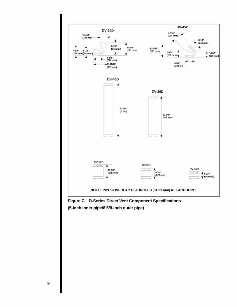
Figure 7. D-Series Direct Vent Component Specifications
(5-inch inner pipe/8 5/8-inch outer pipe)
NOTE: PIPES OVERLAP 1 3/8 INCHES (34.93 mm) AT EACH JOINT.
DV-90D
6 5/32
5 7/87 3/8
DV-45D
6 7/16
11 1/166 1/2
8 5/8
8 1/2
5 1/16
8 /12 11 5/8
8 5/8
11 15/16
DV-36D
35 3/4
47 3/4
DV-48D
5 3/48 3/411 3/4
DV-12DDV-09D
DV-06D
6-5/32"(156 mm)
7-3/8" 5-7/8"(187 mm) (149 mm)
8-1/2"(216 mm)
8-5/8"(220 mm)
11-15/16"(303 mm)
11-5/8"(295 mm)
11-1/16"(281 mm) 6-1/2"
(165 mm)
8-5/8"(220 mm)
5-1/16"(129 mm)
8-1/2"(216 mm)
6-7/16"(164 mm)
35-3/4"(908 mm)
47-3/4"(1.2 m)
11-3/4"(298 mm) 8-3/4"
(222 mm)5-3/4"(146 mm)
NOTE: PIPES OVERLAP 1-3/8 INCHES (34.93 mm) AT EACH JOINT.

10
Figure 8. SL-D-Series Direct Vent Component Specifications
(4-inch inner pipe/6 5/8-inch outer pipe)

11
Figure 9. Vertical Venting
VERTICAL VENTING
V (FT.)
40' MAX. (12.4 M)
NOTE: MODEL 6000 ARCH
A 12-inch length of straight vent pipe MUST bethe first vent component attached to the unit.
V
CAP

12
H
V
H
V
Figure 10. Venting with One 90° Elbow
VENTING WITH ONE (1) 90° ELBOW
V (FT.) H (FT.) (8000 & 6000’s) H (FT.) SL-42DVT
1' MIN. (305 mm) 6' MAX. (1.86 m) 3’ MAX. (914mm)2' MIN. (610 mm) 12' MAX. (3.66 m) 6’ MAX. (1.83m)3' MIN. (914 mm) 18' MAX. (5.58 m) 9’ MAX. (2.74m)4' MIN. (1.22 m) 24' MAX. (8.44 m) 12’ MAX. (3.66m)
20' MAX. (6.2 m) 24' MAX. (8.44 m) 12’ MAX. (3.66m) (21' IN CANADA 6.3 m)
NOTE: MODEL 6000 ARCHA 12-INCH LENGTH OF STRAIGHTVENT PIPE MUST BE THE FIRSTVENT COMPONENT ATTACHEDTO THE UNIT.
FOR 8000DVTFL, 6000DVTFL, 6000XLTNOTE: IF A 90° ELBOW IS FIRSTATTACHED TO THE UNIT, THE MAXIMUMHORIZONTAL RUN H IS 3-FEET (914 MM).
FOR SL-42DVTNOTE: IF A 90° ELBOW IS FIRSTATTACHED TO THE UNIT, THEMAXIMUM HORIZONTAL RUN H IS2-FEET (610 MM).
NOTE: For corner installations: A 6-inch (152mm) MINIMUM length ofstraight pipe must be first attached to the fireplace before 90 O eblow.This will allow the vent pipe to clear the top standoffs.
Model 6000XLT & 8000DVTFL

13
VH
H1H1
Figure 11. Venting with two 90° elbows
VENTING WITH TWO (2) 90° ELBOWSV (FT.) H + H
1 (FT.) (8000 & 6000’s) H + H
1 (FT.) (SL-42DVT)
1' MIN. (305 mm) 6' MAX. (1.86 m) 3' MAX. (914 mm)2' MIN. (610 mm) 12' MAX. (3.72 m) 6' MAX. (1.83 m)3' MIN. (914 mm) 18' MAX. (5.58 m) 9' MAX. (2.74 m)4' MIN. (1.22 m) 24' MAX. (8.44 m) 12' MAX. (3.66 m)
20' MAX. (6.2 m) 24' MAX. (8.44 m) 12' MAX. (3.66 m) (21' IN CANADA 6.5 m)
NOTE: MODEL 6000 ARCH
A 12-inch length of straight vent pipe MUST bethe first vent component attached to the unit.

14
H
V
V1V1
VENTING WITH TWO (2) 90° ELBOWS
V (FT.) H (FT.) (8000 & 6000’s) H (FT.) (SL-42DVT)
1' MIN. (305 mm) 6' MAX. (1.6 m) 3' MAX. (914 mm)2' MIN. (610 mm) 12' MAX. (3.72 m) 6' MAX. (1.86 m)3' MIN. (914 mm) 18' MAX. (5.58 m) 9' MAX. (2.74 m)4' MIN. (1.22 m) 24' MAX. (8.44 m) 12' MAX. (3.66 m)
24' MAX. (8.44 m) 12' MAX. (3.66 m) (21' IN CANADA 6.5 m)
NOTE: V + V1 MAX. 20' (6.2 m)
NOTE: MODEL 6000 ARCH
A 12-inch length of straight vent pipe MUSTbe the first vent component attached to theunit.
Figure 12. Venting with two 90° elbows

15
VENTING WITH THREE (3) 90° ELBOWS
V (FT.) H (FT.) (8000 & 6000’s) H (FT.) (SL-42DVT)
1' MIN. (305 mm) 6' MAX. (1.86 m) 3' MAX. (914 mm)
2' MIN. (610 mm) 12' MAX. (3.72 m) 6' MAX. (1.86 m)3' MIN. (914 mm) 18' MAX. (5.58 m) 9' MAX. (2.74 m)4' MIN. (1.22 m) 24' MAX. (8.44 m) 12' MAX. (3.66 m)
24' MAX. (8.44 m) 12' MAX. (3.66m)NOTE: H + H1 MAX. 24' (8.44 m) (8000 & 6000’s)
NOTE: H + H1 MAX. 12' (3.66 m) (SL-42DVT)
V + V1 MAX. 20' (6.2 m)
H1H1
H
V1V1
V
NOTE: MODEL 6000 ARCH
A 12-inch length of straight vent pipe MUST bethe first vent component attached to the unit.
Figure 13. Venting with three 90° elbows

16
Figure 14. Venting with three 90° elbows
V1V1
H1H1 HV
VENTING WITH THREE (3) 90° ELBOWS
V (FT.) H + H1 (FT.) (8000 & 6000’s) H + H
1 (FT.) (SL-42DVT)
1' MIN. (305 mm) 6' MAX. (1.86 m) 3' MAX. (914 mm)2' MIN. (610 mm) 12' MAX. (3.72 m) 6' MAX. (1.86 m)3' MIN. (914 mm) 18' MAX. (5.58 m) 9' MAX. (2.74 m)4' MIN. (1.22 m) 24' MAX. (8.44 m) 12' MAX. (3.66 m)
24' MAX. (8.44 m) 12' MAX. (3.66 m)NOTE: V + V
1 MAX. 20' (6.2 m)

17
B. Installing Vent Components1. Attach the First Vent Component to the
Starting Collars
To attach the first vent component to the startingcollars of the fireplace:
• Apply a 3/8 inch (9.5 mm) bead of stove cementaround the inner pipe fireplace starting collar.
• Make sure that the fireplace rope gasket suppliedwith the fireplace seals between the firstvent component and the outer fireplace wrap.
• Lock the vent components into place by sliding theconcentric pipe sections with four (4) equallyspaced interior beads into the fireplace collar orpreviously installed component end with four (4)equally spaced indented sections.
• When the internal beads of each outer pipe line up,rotate the pipe section clockwise about one-quarter(1/4) turn. The vent pipe is now locked together.
• The first 90° elbow installed in the vent system of arear venting fireplace MUST BE in a vertical posi-tion.
1. Apply the stove ce-ment.
2. Line up the internalbeads and rotate thepipe sections clock-wise until locked.
3. Lock the vent compo-nents into place.
4. Check the seal on therope gasket.
Figure 15. Attaching the First Vent Component tothe Starting Collars
WARNINGA 3/8 INCH (9.5 MM) BEAD OF STOVECEMENT MUST BE PLACED AROUNDTHE INNER PIPE FIREPLACESTARTING COLLAR BEFOREATTACHING THE FIRST VENTCOMPONENT. FAILURE TO SEAL THISJOINT MAY CAUSE THE FIREPLACE TOOPERATE IMPROPERLY. SEE THEDIAGRAM .
STARTINGCOLLARSTARTINGCOLLAR
FIRSTVENTCOMPONENT
FIRSTVENTCOMPONENT
STOVESEALANTBEAD3/8" (9.5 mm)
STOVESEALANTBEAD3/8" (9.5 mm)
1 INCH (25.4 mm)
3/8 INCH (9.5 mm)

18
WARNINGENSURE THAT THE FIBERGLASSROPE GASKET SUPPLIED WITH THEFIREPLACE SEALS BETWEEN THEFIRST VENT COMPONENT AND THEOUTER FIREPLACE WRAP.
FOR MODEL 6000ARCH:WARNNG: MAKE CERTAIN THAT THEFIBERGLASS INSULATION BAND ISPACKED INTO THE SPACE BETWEENTHE 11-INCH DIAMETER TOP PIPEHEAT SHIELD AND THE STARTERPIPE. SEE FIGURE 16.
Figure 16.
2. Continue Adding Vent Components
To continue adding vent components in accordancewith the pre-planned vent system configuration:
• Ensure that each succeeding vent component issecurely fitted and locked into the preceding com-ponent in the vent system.
90° elbows may be installed and rotated to any pointaround the preceding component’s vertical axis. If anelbow does not end up in a locked position with thepreceding component, attach with a minimum of two(2) sheet metal screws.
FIRST VENTCOMPONENTFIRST VENTCOMPONENT
FIBERGLASSINSULATIONFIBERGLASSINSULATION

19
Continue adding ventcomponents, lockingeach succeedingcomponent into place.
Figure 17. Adding Venting Components
3. Install Support Brackets
For Horizontal Runs - The vent system must besupported every five (5) feet of horizontal run by ahorizontal pipe support.
To install support brackets for horizontal runs:
• Place the pipe supports around the vent pipe.
• Nail the pipe supports to the framing members.

20
For Vertical Runs - The vent system must besupported every eight (8) feet (2.4 m) above thefireplace flue outlet by wall brackets.
To install support brackets for vertical runs:
• Attach wall brackets to the vent pipe and securethe wall bracket to the framing members with nailsor screws.
Use wall brackets tosupport vertical runsevery 8 feet (2.4 m)above the fireplace flueoutlet.
Figure 18. Installing Support Brackets
4. Install Firestops
For Horizontal Runs - Firestops are REQUIREDon both sides of a combustible wall through whichthe vent passes.
NOTE Model DVK-01TRD and SLK-01TRD do not needan exterior firestop on an exterior combustible wall.
To install firestops for horizontal runs that passthrough either interior or exterior walls:
• Cut a 12-inch by 12-inch (305 mm X 305 mm)hole through the wall for D-series or a 10-inch by10-inch (254mm X 254mm) hole for SL-D-seriespipe. The center of the hole is one (1) inch (25.4mm) above the center of the horizontal vent pipe.
8 FT (2.8 m)
WALLBRACKETWALLBRACKET
WALLSTUDWALLSTUD
FLUEOUTLETFLUEOUTLET
1" MIN.25.4 mm)1" MIN.25.4 mm)

21
• Position the firestops on both sides of the holepreviously cut and secure the firestops with nails orscrews.
• The heat shields of the firestops MUST BE placedtowards the top of the hole.
• Continue the vent run through the firestops.
1. Cut the hole throughthe wall.
Figure 19. Hole and Vent Pipe
2. Position the firestops.
3. Place the heat shieldto the top.
4. Continue the vent run.
Figure 20. Heat Shield, Interior and ExteriorFirestops
For Vertical Runs - One ceiling firestop isREQUIRED at the hole in each ceiling through whichthe vent passes.
To install firestops for vertical runs that pass throughceilings:
• Position a plumb bob directly over the center of thevertical vent component.
• Mark the ceiling to establish the centerpoint of thevent.
TRIM HEATSHIELD IF TOOLONG, ADD TOSHIELD IF TOOSHORT.
TRIM HEATSHIELD IF TOOLONG, ADD TOSHIELD IF TOOSHORT.
EXTERIORFIRESTOPEXTERIORFIRESTOP
INTERIORFIRESTOPINTERIORFIRESTOP
HEAT SHIELD

22
• Drill a hole or drive a nail through this centerpoint.
• Check the floor above for any obstructions, suchas wiring or plumbing runs.
• Reposition the fireplace and vent system, if neces-sary, to accommodate the ceiling joists and/orobstructions.
• Cut an 11-inch X 11-inch (280 mm X 280 mm)forD-series or 10-inch X 10-inch (254 mm X 254 mm)for SLD-series pipe hole through the ceiling, usingthe centerpoint previously marked.
• Frame the hole with framing lumber the same sizeas the ceiling joists.
1. Cut the ceiling hole.
2. Add the new framingmembers.
Figure 21. Hole and New Framing Members
If the area above the ceiling is NOT an attic, positionand secure the ceiling firestop on the ceiling side ofthe previously cut and framed hole.
This shows a ceilinginstallation.
Figure 22. Ceiling Firestop (Ceiling Side)
JOIST
CEILING FIRESTOPNAILS (4 REQUIRED)
CEILING

23
If the area above the ceiling IS an attic, position andsecure the firestop on top of the previously framedhole.
This shows an atticinstallation.
1. Keep insulation awayfrom the vent pipe atleast 1 inch (25 mm).
NAILS (4 REQUIRED)
CEILING FIRESTOP
RAFTER
CEILING
Figure 23. Attic Firestop
C. Vent TerminationFor Horizontal Terminations - To attach and securethe termination to the last section of horizontal vent:
• Rotate and interlock the ends as described at thebeginning of the Installing Vent Components sec-tion.
• The termination kit should pass through the wallfirestops from the exterior of the building.
• Adjust the termination cap to its final exterior posi-tion on the building.
WARNINGTHE TERMINATION CAP MUST BEPOSITIONED SO THAT THE ARROW ISPOINTING UP.
For roundcap termination kits:
• Use the exterior pipelock hole provided on the roundflange of the wall firestop to secure the vent pipe inplace.
For trapezoidal cap termination kits:
• Using screws, secure the cap to the exterior wallthrough the flanges built into the cap.
• Use a high-temperature sealant or fiberglass ropegasket to seal between the pipe and exteriorfirestop.

24
For round captermination:
1. Secure the pipe,using the exteriorpipelock hole on theround flange of thewall firestop.
For trapezoidaltermination:
1. Screw the cap to theexterior wall throughthe flanges in the cap.
2. Seal the joint betweenthe pipe and theexterior firestop.
Figure 24. Round and Trapezoid TerminationCaps
WARNINGTHE BOTTOM OF THE VENTTERMINATION CAP MUST BE AMINIMUM OF 12 INCHES (305 MM)ABOVE GROUND LEVEL (GRADE). THETOP OF THE CAP MUST BE A MINIMUMOF 18 INCHES (457 MM) BELOWCOMBUSTIBLE MATERIAL, SUCH AS ADECK, AND THE SIDE OF THE CAPMUST BE A MINIMUM OF 6 INCHES (152MM) AWAY FROM A PARALLEL OUTSIDEWALL. VENTING TERMINALS SHALLNOT BE RECESSED INTO A WALL ORSIDING. SEE THE FOLLOWINGDIAGRAM FOR VENT TERMINATIONCLEARANCES.

25
D
E
BL
v
vv
v
v
v
v
v
openableC
B B
B
fixed closed
A H
MX
J or KI
A
G
F
V =VENT TERMINAL
X =AIR SUPPLY INLET
123123123123 =AREA WHERE TERMINAL IS NOT PERMITTED
A = 12" clearances above grade, veranda, porch, deck or balcony
B = 12" clearances to window or door that may be opened
C = 9" (U.S.A.) clearance to permanently closed window12" (Canada)
D = 18" vertical clearance to ventilated soffit located above theterminal within a horizontal distance of 2 feet (60 cm)from the center-line of the terminal
E = 18" clearance to unventilated soffit
F = 9" clearance to outside corner
G = 6" clearance to inside corner
H = 3 ft. (Canada) not to be installed above a gas meter/regulator assemblywithin 3 feet (90 cm) horizontally from the center-line ofthe regulator
I = 3 ft. (U.S.A.) clearance to service regulator vent outlet6 ft. (Canada)
J = 9" (U.S.A.) clearance to non-mechanical air supply inlet to building12" (Canada) or the combustion air inlet to any other appliance
K = 3 ft. (U.S.A.) clearance to a mechanical air supply inlet6 ft. (Canada)
*L = 7 ft. clearance above paved sidewalk or a paved drivewaylocated on public property
**M = 18" clearance under veranda, porch, deck or balcony
* a vent shall not terminate directly above a sidewalk or paved driveway which islocated between two single family dwellings and serves both dwellings.
** only permitted if veranda, porch, deck or balcony is fully open on a minimum of2 sides beneath the floor.
NOTE: Local Codes or Regulations may require different clearances.
Figure 25. Vent Termination Minimum Clearances
CAUTION IF EXTERIOR WALLS ARE FINISHED WITHVINYL SIDING, IT IS NECESSARY TO INSTALLTHE VINYL PROTECTOR KIT TO THE TOP OFTHE EXTERIOR FIRESTOP (FOR ALL ROUNDTERMINATION CAPS).

26
For Vertical Terminations - To locate the vent andinstall the vent sections:
• Locate and mark the vent centerpoint on theunderside of the roof, and drive a nail through thecenterpoint.
• Make the outline of the roof hole around thecenterpoint nail.
• The size of the roof hole framing dimensionsdepend on the pitch of the roof. There MUST BE a1-inch (25.4 mm) clearance from the vertical ventpipe to combustible materials.
• Mark the roof hole accordingly.
• Cover the opening of the installed vent pipes.
• Cut and frame the roof hole.
• Use framing lumber the same size as the roofrafters and install the frame securely. Flashinganchored to the frame must withstand heavy winds.
• Continue to install concentric vent sections upthrough the roof hole (for inside vent installations) orup past the roof line until you reach the appropriatedistance above the roof (for outside terminations).
WARNINGMAJOR U.S. BUILDING CODESSPECIFY MINIMUM CHIMNEY AND/ORVENT HEIGHT ABOVE THE ROOF TOP.THESE MINIMUM HEIGHTS ARENECESSARY IN THE INTEREST OFSAFETY. SEE THE FOLLOWINGDIAGRAM FOR MINIMUM HEIGHTS,PROVIDED THE TERMINATION CAP ISAT LEAST EIGHT (2) FEET FROM AVERTICAL WALL AND 2-FEET BELOWA HORIZONTAL OVERHANG.
NOTE This also pertains to vertical vent systems installedon the outside of the building.

27
Roof Pitch H (min.) ft.
flat to 6/12 1.06/12 to 7/12 1.25over 7/12 to 8/12 1.5over 8/12 to 9/12 2.0over 9/12 to 10/12 2.5over 10/12 to 11/12 3.25over 11/12 to 12/12 4.0over 12/12 to 14/12 5.0over 14/12 to 16/12 6.0over 16/12 to 18/12 7.0over 18/12 to 20/12 7.5over 20/12 to 21/12 8.0
Figure 26. Minimum Height from Roof to LowestDischarge Opening
To seal the roof hole, and to divert rain and snow fromthe vent system:
• Attach a flashing to the roof using nails, and use anon-hardening mastic around the edges of theflashing base where it meets the roof.
• Attach a storm collar over the flashing joint to form awater-tight seal. Place non-hardening masticaround the joint, between the storm collar and thevertical pipe.
• Slide the termination cap over the end of the ventpipe and rotate the pipe clockwise 1/4 turn.
1. Attach the flashingand apply sealantaround the edges ofthe flashing base.
2. Attach the stormcollar over the flashingjoint and apply sealantbetween the stormcollar and verticalpipe.
TERMINATIONCAP

28
The diagram below shows how to properly position,level, and secure the fireplace.
1. Place the fireplaceinto position.
2. Level the fireplacefrom side to side andfrom front to back.
3. Shim the fireplacewith non-combus-tible material, suchas sheet metal, asnecessary.
4. Secure the fireplaceto the framing bynailing or screwing
Figure 27. Proper Positioning, Leveling, andSecuring of a Fireplace
Step 5The Gas ControlSystems
WARNINGTHIS UNIT IS NOT FOR USE WITHSOLID FUEL.
Two types of gas control systems are used withthese models: Standing Pilot Ignition and DirectSpark Ignition (DSI). Model 6000XLT has StandingPilot Ignition only. Model 6000ARCH has DSI only.
Standing Pilot Ignition SystemThis system includes millivolt control valve, standingpilot, thermopile/thermocouple flame sensor, andpiezo ignitor.
WARNING110-120 VAC MUST NEVER BECONNECTED TO A CONTROL VALVEIN A MILLIVOLT SYSTEM.
Direct Spark Ignition (DSI) SystemThis system includes a 24V control valve, electronicmodule, transformer, and spark ignitor/flame sensor.
WARNING110-120 VAC MUST BE WIRED TO THEFIREPLACE JUNCTION BOX IN A DSISYSTEM.
WARNINGDIRECT VENT PROPANE MODELSWITH DSI CONTROL SYSTEMSCANNOT BE USED IN CANADA.
Step 4Positioning,Leveling, andSecuring theFireplace

29
Figure 28. Gas Controls Systems
Step 6The GasSupply Line
NOTE: Have the gas supply line installed by aqualified service technician in accordance with allbuilding codes .
NOTE: Before the first firing of the fireplace, thegas supply line should be purged of any trapped air.
NOTE: Consult local building codes to properly sizethe gas supply line leading to the 1/2 inch(13 mm) hook-up at the unit.
This gas fireplace is designed to accept a 1/2 inch(13 mm) gas supply line.
To install the gas supply line:• A listed 1/2 inch (13 mm) manual shut-off valve and a
listed flexible gas connector are connected to the 1/2inch (13 mm) inlet of the control valve.
• A 1/8 inch (3 mm) N.P.T. plugged tapping, accessiblefor test gauge connection, should be provided for inthe gas supply line leading to the unit’s shut-off valve.
• Locate the gas line access hole in the outer casing ofthe fireplace.
• Open the fireplace lower grille, insert the gas supplyline through the gas line hole, and connect it to theshut-off valve.
• When attaching the pipe, support the control so thatthe lines are not bent or torn.
• After the gas line installation is complete, use a soapsolution to carefully check all gas connections forleaks.
WARNINGDO NOT USE AN OPEN FLAME TOCHECK FOR GAS LEAKS .
3/16" (5 mm)
DSI IGNITION
IGNITOR
1/2" (13 mm)1/2" (13 mm)
STANDING PILOT
3/8" (10 mm)

30
• At the gas line access hole, use insulation to re-pack the space around the gas pipe.
• Insert insulation from the outside of the fireplaceand pack the insulation tightly to totally seal be-tween the pipe and the outer casing.
The gas line should beinstalled by a qualifiedservice technician.
Figure 29. Gas Supply Line
Step 7Gas PressureRequirements
Pressure requirements for Heat-N-Glo gas fireplacesare shown in the table below.
Pressure Natural Gas Propane
Minimum 5.0 inches 11.0 inchesInlet Pressure w.c. w.c.
Maximum Inlet 14.0 inches 14.0 inchesGas Pressure w.c. w.c.
Manifold 3.5 inches 10.0 inchesPressure w.c. w.c.
A one-eighth (1/8) inch (3 mm) N.P.T. plugged tappingis provided on the outlet side of the gas control for atest gauge connection to measure the manifoldpressure. To measure inlet pressure, provisions mustbe made to attach a test gauge to a one-eighth (1/8)inch (3 mm) N.P.T. plugged tapping immediatelyupstream of the gas supply connection to thefireplace.
The fireplace and its individual shut-off valve must bedisconnected from the gas supply piping systemduring any pressure testing of the system at testpressures in excess of one-half (1/2) psig (3.5 kPa).
The fireplace must be isolated from the gas supplypiping system by closing its individual shut-off valveduring any pressure testing of the gas supply pipingsystem at test pressures equal to or less than one-half (1/2) psig (3.5 kPa).

31
Step 8Wiring theFireplace
NOTE: Electrical wiring must be installed by alicensed electrician.
For Standing Pilot Ignition Wiring
Appliance Requirements• This appliance DOES NOT require 110-120 VAC to
operate.
WARNINGDO NOT CONNECT 110-120 VAC TO THEGAS CONTROL VALVE OR THEAPPLIANCE WILL MALFUNCTION ANDTHE VALVE WILL BE DESTROYED .
Optional AccessoriesOptional fan and remote control kits require that 110-120 VAC be wired to the factory installed junction boxbefore the fireplace is permanently installed.
Remote Wall SwitchPosition the remote wall switch in the desired positionon a wall. Run a maximum of 25 feet (7.8 m) or lesslength of 18 A.W.G. minimum wire and connect it tothe fireplace ON/OFF switch pigtails.
WARNINGDO NOT CONNECT 110-120 VAC TO THEREMOTE WALL SWITCH OR THECONTROL VALVE WILL BEDESTROYED.
CAUTION LABEL ALL WIRES PRIOR TO DISCONNECTIONWHEN SERVICING CONTROLS. WIRINGERRORS CAN CAUSE IMPROPER ANDDANGEROUS OPERATION. VERIFY PROPEROPERATION AFTER SERVICING.
Figure 30. Standing Pilot Ignition Wiring Diagram
NOTE: MODEL SL-42DVTDOES NOT HAVE A HI-TEMPLIMIT SWITCH.

32
NOTE: IF ANY OF THE ORIGINAL WIREAS SUPPLIED WITH THE APPLIANCEMUST BE REPLACED, IT MUST BEREPLACED WITH TYPE 105 DEGREE CRATED WIRE.
NOTE: IF ANY OF THE ORIGINAL WIREAS SUPPLIED WITH THE APPLIANCEMUST BE REPLACED, IT MUST BEREPLACED WITH TYPE 105 DEGREE CRATED WIRE.
BLOWER
BLOWER RECEPTACLE
JUNCTION BOX
VARIABLE SPEED CONTROL
TEMPERATURESENSOR SWITCHTEMPERATURESENSOR SWITCH
GROUND
WHT
BLK
BLK
GRN
WHT
BLK
BLK
BLK
BLK
BLK
BLK
BLK
110-120 VAC
BLK
WHT
FAN WIRING DIAGRAM
Figure 31. Fan Wiring Diagram
For Direct Spark Ignition (DSI) Wiring
Appliance RequirementsThis appliance requires that 110-120 VAC be wired tothe factory installed junction box. Maintain correctpolarity when wiring the junction box.
Optional AccessoriesOptional fan and remote control kits require that 110-120 VAC be wired to the fireplace junction box.
Remote Wall SwitchPosition the remote wall switch in the desired positionon a wall. Run a maximum of 25 feet(7.8 m) or less of 16 A.W.G. minimum wire andconnect it to the fireplace ON/OFF switch pigtails.
NOTE Electrical wiring must be installed by a licensedelectrician.
CAUTION LABEL ALL WIRES PRIOR TO DISCONNECTIONWHEN SERVICING CONTROLS. WIRINGERRORS CAN CAUSE IMPROPER ANDDANGEROUS OPERATION. VERIFY PROPEROPERATION AFTER SERVICING.
TEMPERATURESENSOR SWITCH
JUNCTIONBOX
FAN SPEED CONTROL(RHEOSTAT)

33
Figure 32. Direct Spark Ignition (DSI) Wiring Diagram
Step 9Finishing
The following diagram shows the minimum verticaland corresponding maximum horizontal dimensionsof fireplace mantels or other combustible projectionsabove the top front edge of the fireplace. See Figure 5for other fireplace clearances.
Only non-combustiblematerials may be usedto cover the blackfireplace front.
Figure 33. Minimum Vertical and MaximumHorizontal Dimensions ofCombustibles above Fireplace
WARNINGWHEN FINISHING THE FIREPLACE,NEVER OBSTRUCT OR MODIFY THEAIR INLET/OUTLET GRILLES IN ANYMANNER.
1.5"3" 3.5"
4" 4.5" 5"6" 7"
8" 9"10"
11"
1"
2"3"
4"5"
12"11"
10"9"
8"7"
6"
TOP FRONT EDGEOF FIREPLACETOP FRONT EDGEOF FIREPLACE
NOTE: ALL DIMENSIONS SHOWNIN INCHES.NOTE: ALL DIMENSIONS SHOWNIN INCHES.
NOTE: MODELS SL-42DVT &6000ARCH DO NOT HAVE AHI-TEMP. LIMIT SWITCH.

34
Installing the TrimCombustible materials may be brought up to thespecified clearances on the side and top front edges ofthe fireplace, but MUST NEVER overlap onto the frontface. The joints between the finished wall and thefireplace top and sides can only be sealed with a 300°
F. (149° C) minimum sealant.
WARNINGWHEN FINISHING THE FIREPLACE,NEVER OBSTRUCT OR MODIFY THEAIR INLET/OUTLET GRILLES IN ANYMANNER.
Install optional marble and brass trim surround kits asdesired. Marble, brass, brick, tile, or other non-combustible materials can be used to cover up thegap between the sheet rock and the fireplace.
Do not obstruct or modify the air inlet/outlet grilles.When overlapping on both sides, leave enough spaceso that the bottom grille can be lowered and the trimdoor removed.
CAUTION IF JOINTS BETWEEN THE FINISHED WALLSAND THE FIREPLACE SURROUND (TOP ANDSIDES) ARE SEALED, A 300° F. MINIMUMSEALANT MATERIAL MUST BE USED. THESEJOINTS ARE NOT REQUIRED TO BE SEALED.ONLY NON-COMBUSTIBLE MATERIAL (USING300° F. MINIMUM ADHESIVE, IF NEEDED) CANBE APPLIED AS FACING TO THE FIREPLACESURROUND. SEE THE DIAGRAM SHOWNBELOW.
1. Seal the joints.
2. Apply only non-combustible facingmaterial to the fire-place surround.
Figure 34. Sealant Material
Hearth ExtensionsA hearth extension may be desirable for aestheticreasons. However, ANSI or CAN/CGA testingstandards do not require hearth extensions for gasfireplace appliances.
Step 10Installing Trim,Logs, andEmber Material
35
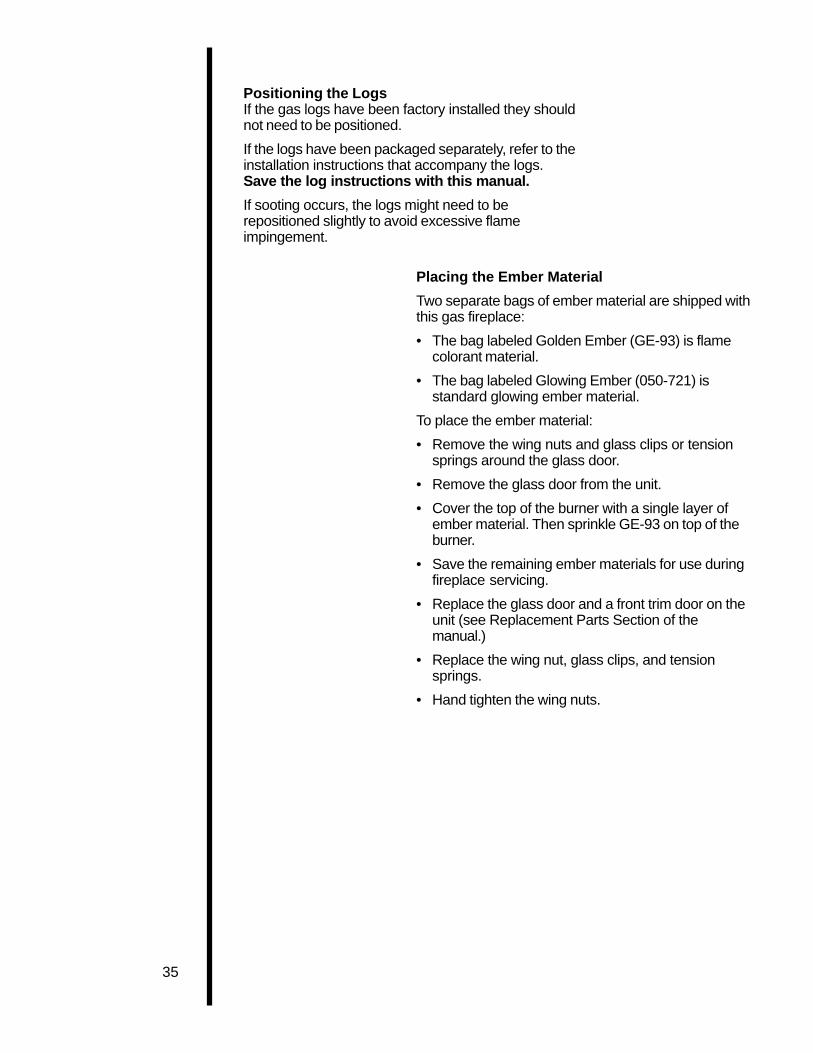
Positioning the LogsIf the gas logs have been factory installed they shouldnot need to be positioned.
If the logs have been packaged separately, refer to theinstallation instructions that accompany the logs.Save the log instructions with this manual.
If sooting occurs, the logs might need to berepositioned slightly to avoid excessive flameimpingement.
Placing the Ember Material
Two separate bags of ember material are shipped withthis gas fireplace:
• The bag labeled Golden Ember (GE-93) is flamecolorant material.
• The bag labeled Glowing Ember (050-721) isstandard glowing ember material.
To place the ember material:
• Remove the wing nuts and glass clips or tensionsprings around the glass door.
• Remove the glass door from the unit.
• Cover the top of the burner with a single layer ofember material. Then sprinkle GE-93 on top of theburner.
• Save the remaining ember materials for use duringfireplace servicing.
• Replace the glass door and a front trim door on theunit (see Replacement Parts Section of themanual.)
• Replace the wing nut, glass clips, and tensionsprings.
• Hand tighten the wing nuts.

36
1. Lift the trim door upand out of the unit.
2. Remove the wingnuts, glass clips, andthe glass door fromthe unit.
Figure 35. Glass Assembly
CAUTION HAND TIGHTEN THE WING NUTS, BUT BECAREFUL NOT TO OVERTIGHTEN.
1. Place the embermaterial onto the topof the burner.
Figure 36. Placement of the Ember Material
CAUTION IT IS STRONGLY RECOMMENDED THAT TRIMDOORS WITH OPTIIONAL MESH SCREENS BEINSTALLED ON PROPANE MODELS.

37
Step 11Before Lightingthe Fireplace
Before lighting the fireplace, be sure to do thefollowing:
Review safety warnings and cautions
• Read the Safety and Warning Information sectionat the beginning of this Installers Guide.
Double-check for gas leaks
• Before lighting the fireplace, double-check the unitfor possible gas leaks.
Double-check vent terminations and front grillesfor obstructions.
• Before lighting the fireplace, double-check the unitfor possible obstructions that could be blocking thevent terminations or the front grilles.
Double-check for faulty components
• Any component that is found to be faulty MUST BEreplaced with an approved component. Tamperingwith the fireplace components is DANGEROUS andvoids all warranties.
A small amount of air will be in the gas supply lines.When first lighting the fireplace, it will take a fewminutes for the lines to purge themselves of this air.Once the purging is complete, the fireplace will lightand will operate normally.
Subsequent lightings of the fireplace will not require thispurging of air from the gas supply lines, unless thegas valve has been turned to the OFF position , inwhich case the air would have to be purged.
Step 12Lighting theFireplace
You’ve reviewed all safety warnings, you’ve checkedthe fireplace for gas leaks, you know the vent system isunobstructed, and you’ve checked for faultycomponents. Now you’re ready to light the fireplace.
WARNINGPLEASE REFER TO THE USER’SMANUAL FOR ALL CAUTIONS, SAFETY,AND WARNING INFORMATIONPERTAINING TO THE LIGHTING ANDOPERATION OF THE FIREPLACE.
After theInstallationAfter theInstallation
LEAVE THIS INSTALLATION MANUALWITH THE APPLIANCE FOR FUTUREREFERENCE.

38
4MaintainingandServicingYourFireplace
FireplaceMaintenance
Although the frequency of your fireplace servicing andmaintenance will depend on use and the type ofinstallation, you should have a qualified servicetechnician perform an appliance check-up at thebeginning of each heating season. See the table belowfor specific guidelines regarding each fireplacemaintenance task.
IMPORTANT TURN OFF THE GAS BEFORE SERVICINGYOUR FIREPLACE.
Type ofFireplace Fireplace Maintenance Task To
Maintenance Frequency By Be Completed
Replacing Once annually, Qualified Brush away loose ember material nearOld Ember during the Service the burner. Replace old emberMaterial annual check-up Technician material with new dime-size and -shape
pieces of Golden Ember (GE-93) andGlowing Ember (050-721). New embermaterial should be placed alternately ontop of the burner�a layer of GoldenEmber, a layer of Glowing Ember,and so on. Save the remaining embermaterial and repeat this procedure atyour next servicing. For moreinformation, see Placing EmberMaterial in this manual.
Cleaning Once annually Qualified Brush or vacuum the controlBurner Service compartment, fireplace logs, and& Controls Technician burner areas surrounding the logs.
Checking Periodically Qualified Make a visual check of your fireplace�sFlame Service flame patterns. Make sure the flamesPatterns, Technician are steady�not lifting or floating. SeeFlame Height the picture in Figure 37. The flame ensor
(DSI) or thermopile/thermocouple(standing pilot) tips should be coveredwith flame. See the picture in Figure 38.
Checking Before initial use Qualified Inspect the external vent cap on aVent System and at least Service regular basis to ensure that no debris is
annually thereafter, Technician/ interfering with the flow of air.more frequently Ownerif possible
Cleaning As necessary Homeowner Clean as necessary, particularly afterGlass Door adding new ember (flame colorant)
material. Film deposits on the inside ofthe glass door should be cleaned offusing a household glass cleaner.NOTE: DO NOT handle or attempt toclean the door when it is hot andDO NOT use abrasive cleaners.

39
STANDING PILOT
3/8" (10 mm)
NOTE: FLAMESTOO CLOSE TOTHE CERAMICINSULATORS CANCAUSE NUISANCELOCKOUTS ANDELECTRODEFAILURE.
DSI IGNITION
CERAMICINSULATOR
3/16" (5 mm)
IGNITOR
1/2” (13mm)
Figure 37. Burner Flame Patterns
MAKE SURE THE FLAMESARE STEADY—NOTLIFTING OR FLOATING.
Figure 38. Pilot/Ignitor Flame Patterns

40
5ReplacementParts andAccessories
All parts listed in this INSTALLERS GUIDE may beordered from an authorized dealer. When requestingservice or replacement parts for your fireplace, pleaseprovide the model number and the serial number.
Standing Pilot Only
PART PART DESCRIPTION PART NUMBER
Valve LP (8000 & 6000’S) SRV60-523
Valve NG (8000 & 6000’S) SRV60-522
Valve LP (SL-42DVT) SRV60-521
VAlve NG (SL-42DVT) SRV60-520
Piezo Ignitor SRV60–513
Thermopile SRV60–512
Thermocouple SRV446-511
Pilot Orifice LP SRV446–517
Pilot Orifice NG SRV446–505
Pilot Assembly LP SRV446-511A
Pilot Assembly NG SRV446-510A
Pilot Tube SRV446-301
Burner Tube
8000DVTFL SRV410-302
6000 Models SRV60-307
SL-42DVT SRV486-300

41
DSI Ignition Only(8000DVTFL, 6000DVTFL, 6000ARCH, SL-42DVT)
PART PART DESCRIPTION PART NUMBER
DSI Valve LP SRV77–501
DSI Valve NG SRV77–500
Transformer SRV60–599
DSI Module SRV420–592
Electrode SRV77–591
Burner Tube
- 8000DVTFL SRV410–303
- 6000DVTFL, 6000ARCH SRV422–302
- SL-42DVT SRV486-302
42
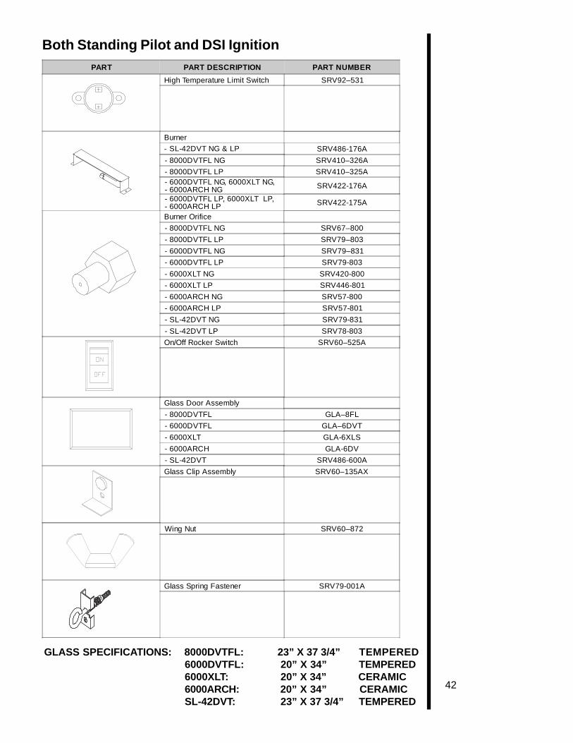
Both Standing Pilot and DSI Ignition
GLASS SPECIFICATIONS: 8000DVTFL: 23” X 37 3/4” TEMPERED6000DVTFL: 20” X 34” TEMPERED6000XLT: 20” X 34” CERAMIC6000ARCH: 20” X 34” CERAMICSL-42DVT: 23” X 37 3/4” TEMPERED
PART PART DESCRIPTION PART NUMBER
High Temperature Limit Switch SRV92–531
Burner
- SL-42DVT NG & LP SRV486-176A
- 8000DVTFL NG SRV410–326A
- 8000DVTFL LP SRV410–325A- 6000DVTFL NG, 6000XLT NG,- 6000ARCH NG SRV422-176A
- 6000DVTFL LP, 6000XLT LP,- 6000ARCH LP SRV422-175A
Burner Orifice
- 8000DVTFL NG SRV67–800
- 8000DVTFL LP SRV79–803
- 6000DVTFL NG SRV79–831
- 6000DVTFL LP SRV79-803
- 6000XLT NG SRV420-800
- 6000XLT LP SRV446-801
- 6000ARCH NG SRV57-800
- 6000ARCH LP SRV57-801
- SL-42DVT NG SRV79-831
- SL-42DVT LP SRV78-803
On/Off Rocker Switch SRV60–525A
Glass Door Assembly
- 8000DVTFL GLA–8FL
- 6000DVTFL GLA–6DVT
- 6000XLT GLA-6XLS
- 6000ARCH GLA-6DV
- SL-42DVT SRV486-600A
Glass Clip Assembly SRV60–135AX
Wing Nut SRV60–872
Glass Spring Fastener SRV79-001A

43
Both Standing Pilot and DSI Ignition (Cont.)
Accessories
PART PART DESCRIPTION PART NUMBER
Trim Door
- 8000DVTFL DF–8000
- 6000 MODELS (MESH) DF-6000
- 6000 MODELS (NO MESH) DF-36
- SL-42DVT DF-8000-BK
Log Set Assembly
- 8000DVTFL LOGS-8FL
- 6000DVTFL LOGS-6FL
- 6000XLT LOGS-CAMP
- SL-42DVT LOGS-SL42
Bottom Right RefractorySL-42DVT SRV486-370
Bottom Left RefractorySL-42DVT SRV486-371
Grate Assembly SL-42DVT SRV486-360A
ACCESSORY PART DESCRIPTION PART NUMBER
Fan Kit GFK-160A
GFK-270
Remote Control Kit RCH-09A
RC-SMART
SMART-STAT
RC-MLT
Wall Switch Kit
- Off White WSK-21
- White WSK-21-W
Trim Door Mesh (SL-42DVT) MESH-42
Nat. Gas LPG
Refractory (SL-42DVT) MET-REF-42