Heat-N-Glo Fireplacecontent.hearthnhome.com/downloads/installManuals/402_982-a.pdfHeat-N-Glo...
38
- Do not store or use gasoline or other flam- mable vapors and liquids in the vicinity of this or any other appliance. - What to do if you smell gas • Do not try to light any appliance. • Do not touch any electrical switch. • Do not use any phone in your building. • Immediately call your gas supplier from a neighbor's phone. Follow the gas supplier's instructions. • If you cannot reach your gas supplier, call the fire department. - Installation and service must be performed by a qualified installer, service agency, or the gas supplier. Heat-N-Glo Fireplace Models: Townsend I and II Installers Guide WARNING: IMPROPER INSTALLA- TION, ADJUSTMENT, ALTERATION, SERVICE OR MAINTENANCE CAN CAUSE INJURY OR PROPERTY DAM- AGE. REFER TO THIS MANUAL. FOR ASSISTANCE OR ADDITIONAL INFOR- MATION CONSULT A QUALIFIED INSTALLER, SERVICE AGENCY, OR THE GAS SUPPLIER. 402-982-A 11/98 READ THIS MANUAL BEFORE INSTALLING OR OPERATING THIS APPLIANCE. THIS INSTALLERS GUIDE MUST BE LEFT WITH THE APPLIANCE FOR FUTURE REFERENCE. 1. This appliance may be installed in an aftermarket, permanently located, manufactured (mobile) home, where not prohibited by local codes. 2. This appliance is only for use with the type of gas indicated on the rating plate. This appliance is not convertible for use with other gases, unless a certified kit is used. Please contact your Heat-N-Glo dealer for any questions or concerns. For the number of your nearest Heat-N-Glo dealer, please call 612-890-8367. Printed in U.S.A. Copyright 1998, Heat-N-Glo, a division of Hearth Technologies Inc. 6665 West Highway 13, Savage, MN 55378 WARNING: IF THE INFORMATION IN THESE INSTRUCTIONS IS NOT FOLLOWED EXACTLY, A FIRE OR EXPLOSION MAY RESULT CAUSING PROPERTY DAMAGE, PERSONAL INJURY, OR DEATH. This product is covered by one or more of the following patents: (United States) 4,112,913; 4,408,594; 4,422,426; 4,424,792; 4,520,791; 4,793,322; 4,852,548; 4,875,464; 5,000,162; 5,016,609; 5,076,254 5,191,877; 5,218,953; 5,328,356; 5,429,495; 5,452,708; 5,542,407; 5,613,487; (Australia) 543790; 586383; (Canada) 1,123,296; 1,297,746; 2,195,264; (Mexico) 97-0457; (New Zealand) 200265; or other U.S. and foreign patents pending. Underwriters Laboratories Listed
Transcript of Heat-N-Glo Fireplacecontent.hearthnhome.com/downloads/installManuals/402_982-a.pdfHeat-N-Glo...

- Do not store or use gasoline or other flam-mable vapors and liquids in the vicinity ofthis or any other appliance.
- What to do if you smell gas• Do not try to light any appliance.
• Do not touch any electrical switch.
• Do not use any phone in your building.
• Immediately call your gas supplier from aneighbor's phone. Follow the gas supplier'sinstructions.
• If you cannot reach your gas supplier, callthe fire department.
- Installation and service must be performed by aqualified installer, service agency, or the gassupplier.
Heat-N-Glo FireplaceModels:Townsend I and II
Installers Guide
WARNING: IMPROPER INSTALLA-TION, ADJUSTMENT, ALTERATION,SERVICE OR MAINTENANCE CANCAUSE INJURY OR PROPERTY DAM-AGE. REFER TO THIS MANUAL. FORASSISTANCE OR ADDITIONAL INFOR-MATION CONSULT A QUALIFIEDINSTALLER, SERVICE AGENCY, ORTHE GAS SUPPLIER.
402-982-A 11/98
READ THIS MANUAL BEFORE INSTALLINGOR OPERATING THIS APPLIANCE. THISINSTALLERS GUIDE MUST BE LEFT WITHTHE APPLIANCE FOR FUTURE REFERENCE.
1. This appliance may be installed in anaftermarket, permanently located,manufactured (mobile) home, wherenot prohibited by local codes.
2. This appliance is only for use with thetype of gas indicated on the ratingplate. This appliance is not convertiblefor use with other gases, unless acertified kit is used.
Please contact your Heat-N-Glo dealer for anyquestions or concerns. For the number of your nearestHeat-N-Glo dealer, please call 612-890-8367.
Printed in U.S.A. Copyright 1998,
Heat-N-Glo, a division of Hearth Technologies Inc.6665 West Highway 13, Savage, MN 55378
WARNING: IF THE INFORMATION INTHESE INSTRUCTIONS IS NOTFOLLOWED EXACTLY, A FIRE OREXPLOSION MAY RESULT CAUSINGPROPERTY DAMAGE, PERSONALINJURY, OR DEATH.
This product is covered by one or more of the following patents: (United States) 4,112,913; 4,408,594; 4,422,426; 4,424,792; 4,520,791; 4,793,322;4,852,548; 4,875,464; 5,000,162; 5,016,609; 5,076,254 5,191,877; 5,218,953; 5,328,356; 5,429,495; 5,452,708; 5,542,407; 5,613,487; (Australia) 543790; 586383;(Canada) 1 ,123 ,296 ; 1 ,297 ,746 ; 2 ,195 ,264 ; (Mex ico) 97-0457; (New Zea land) 200265; o r o ther U .S . and fo re ign pa ten ts pend ing .
UnderwritersLaboratories Listed
Note
This document was designed to be distributed electronically and then printed on a laser printer on an as-needed basis. For this reason, the fonts and layout of this document have been chosen for optimal printing rather than for optimal viewing on-screen. To review this document on-screen, however, simply increase the magnification using the magnification box at the bottom of the window. For the best results when viewing dialog boxes on-screen, increase the magnification to 200%. Please refer to the page number on the bottom right corner of the actual installation manual page for correct paging. This page is the cover page and not page 1.

!
!
!
!
!
!
!
!
!
!
!
!
!
!
!
!
!
!i
SAFETY AND WARNING INFORMATION
READ and UNDERSTAND all instructions carefully before starting the installation.FAILURE TO FOLLOW these installation instructions may result in a possible firehazard and will void the warranty.
Prior to the first firing of the fireplace, READ the Using Your Fireplace section of theOwners Guide.
DO NOT USE this appliance if any part has been under water. Immediately CALL aqualified service technician to inspect the unit and to replace any part of the controlsystem and any gas control which has been underwater.
THIS UNIT IS NOT FOR USE WITH SOLID FUEL.
Installation and repair should be PERFORMED by a qualified service person. Theappliance and venting system should be INSPECTED before initial use and at leastannually by a professional service person. More frequent cleaning may be requireddue to excessive lint from carpeting, bedding material, etc. It is IMPERATIVE that theunit’s control compartment, burners, and circulating air passageways BE KEPTCLEAN to provide for adequate combustion and ventilation air.
Always KEEP the appliance clear and free from combustible materials, gasoline, andother flammable vapors and liquids.
NEVER OBSTRUCT the flow of combustion and ventilation air. Keep the front of theappliance CLEAR of all obstacles and materials for sevicing and proper operations.
Due to the high temperature, the appliance should be LOCATED out of traffic areasand away from furniture and draperies. Clothing or flammable material SHOULD NOTBE PLACED on or near the appliance.
Children and adults should be ALERTED to the hazards of high surface temperatureand should STAY AWAY to avoid burns or clothing ignition. Young children should beCAREFULLY SUPERVISED when they are in the same room as the appliance.
These units MUST use one of the vent systems described in the Installing the Fireplacesection of the Installers Guide. NO OTHER vent systems or components MAY BE USED.
This gas fireplace and vent assembly MUST be vented directly to the outside andMUST NEVER be attached to a chimney serving a separate solid fuel burningappliance. Each gas appliance MUST USE a separate vent system. Common ventsystems are PROHIBITED.
INSPECT the external vent cap on a regular basis to make sure that no debris isinterfering with the air flow.
The glass door assembly MUST be in place and sealed, and the trim door assemblyMUST be in place on the fireplace before the unit can be placed into safe operation.
DO NOT OPERATE this appliance with the glass door removed, cracked, or broken.Replacement of the glass door should be performed by a licensed or qualified serviceperson. DO NOT strike or slam the glass door.
The glass door assembly SHALL ONLY be replaced as a complete unit, as suppliedby the gas fireplace manufacturer. NO SUBSTITUTE material may be used.
DO NOT USE abrasive cleaners on the glass door assembly. DO NOT ATTEMPT toclean the glass door when it is hot.
Turn off the gas before servicing this appliance. It is recommended that aqualified service technician perform an appliance check-up at the beginningof each heating season.
Any safety screen or guard removed for servicing must be replaced before operatingthis appliance.

Table ofContents
i i
Safety and Warning Information ........................... i
Section 1: Approvals and Codes........................ .1Approval Listings and Codes ..................................... 1
Appliance Certification ............................................... 1
Installation Codes ...................................................... 1
High Altitude Installations ........................................... 1
Section 2: Getting Started .................................... 2Introducing the Heat-N-Glo Direct Vent Gas Stoves..... 2
Pre-installation Preparation ........................................ 2
Section 3: Installing the Stove ............................. 5Step 1 Locating the Stove ...................................... 5
Step 2 Setting Up the Stove ................................... 6
Step 3 Installing the Vent System ........................... 7
A. Vent System Approvals ........................... 7
B. Installing Vent Components ................... 14
C. Vent Termination .................................... 19
Step 4 The Gas Control System .......................... 24
Step 5 The Gas Supply Line................................. 24
Step 6 Gas Pressure Requirements .................... 25
Step 7 Wiring the Stove ........................................ 26
Step 8 Finishing .................................................... 27
Step 9 Installing Logs and Ember Material ........... 27
Positioning the Logs .................................. 27
Placing the Ember Material ....................... 27
Step 10 Before Lighting the Stove .......................... 28
Step 11 Lighting the Stove ...................................... 28
After the Installation ................................... 28
Section 4: Maintenance and Servicing .............. 29
Section 5: Replacement Partsand Accessories ............................... 31
Replacement Parts .................................................. 31
Accessories .......................................................... 35

1
Approval Listingsand Codes
Appliance CertificationThe Heat-N-Glo gas stove models discussed in thisInstallers Guide have been tested to certificationstandards and listed by the applicable laboratories.
CERTIFICATION MODEL LABORATORY TYPE STANDARDTownsend I & II Underwriters Vented Gas ANSI Z21.88• CSA2.33 Laboratories Fireplace Heater
Installation CodesInstallation must conform to local codes. In the absence of local codes installationmust conform with the current National Fuel Gas Code ANSI Z223.1 (in the UnitedStates) or with the current installation code CAN/CGA - B149 (in Canada).
The appliance when installed must be electrically grounded in accordance withlocal codes; in absence of local codes, with the current National Electric CodeANSI/ NFPA NO. 70 (in the United States) or with the current CSA C22.1 Cana-dian Electric Code (in Canada).
High Altitude InstallationsThese units are tested and approved for elevations from 0-2000 feet. (In the UnitedStates) and 0-4500 feet (in Canada).
When installing this unit at an elevation above 2000 feet, (in United States) it maybe necessary to decrease the input rating by changing the existing burner orificeto a smaller size. Input should be reduced 4 percent for each 1000 feet above sealevel. Check with your local gas company for help in determining the proper ori-fice size.
When installing this unit at an elevation above 4500 feet (in Canada), check withlocal authorities.
Consult your local gas company for assistance in determining the proper orificefor location.
1Approvals andRegulations

2
Heat-N-Glo direct vent gas stoves are designed tooperate with all combustion air siphoned from outsideof the building and all exhaust gases expelled to theoutside.
The information contained in this Installers Guide,unless noted otherwise, applies to all models and gascontrol systems.
Gas stove diagrams, including the dimensions, areshown in this section.
Pre-installationPreparation
This gas stove and its components are tested andsafe when installed in accordance with this InstallersGuide. Report to your dealer any parts damaged inshipment, particularly the condition of the glass. Donot install any unit with damaged, incomplete, orsubstitute parts.
The vent system components and trim doors areshipped in separate packages. The gas logs arepackaged separately and must be field installed.Read all of the instructions before starting theinstallation. Follow these instructions carefullyduring the installation to ensure maximum safetyand benefit. Failure to follow these instructionswill void the owner’s warranty and may present afire hazard.
The Heat-N-Glo Warranty will be voided by, and Heat-N-Glo disclaims any responsibility for, the followingactions:
• Installation of any damaged stove or vent systemcomponent.
• Modification of the stove or vent system.
• Installation other than as instructed by Heat-N-Glo.
• Improper positioning of the gas logs or the glassdoor.
• Installation and/or use of any component part notmanufactured and approved by Heat-N-Glo, notwithstanding any independent testing laboratory orother party approval of such component part oraccessory.
ANY SUCH ACTION MAY POSSIBLY CAUSE AFIRE HAZARD.
2GettingStarted
Introducing theHeat-N-GloDirect VentGas Stoves

3
Figure 1. Diagram of the TOWNSEND-I
When planning a stove installation, it’s necessary to determine:
• Where the unit is to be installed.
• The vent system configuration to be used.
• Gas supply piping.
• Electrical wiring.
• Framing and finishing details.
• Whether optional accessories—devices such as a fan, wall switch, or remotecontrol—are desired.
If the stove is to be installed on carpeting or tile, or on any combustible materialother than wood flooring, the stove should be installed on a metal or wood panelthat extends the full width and depth of the stove.

4
Figure 2. Diagram of the TOWNSEND-II

5
3Installingthe Stove
Figure 3. Stove Dimensions, Locations, and Space Requirements
TOWNSEND I
TOWNSEND II
The diagram below shows space and clearancerequirements for locating the stove within a room.
Step 1Locating theStove

6
Step 2Setting up theStove
Removal of the cast front surround:
1. Remove the two small bolts from underneath thefront of the cast bottom. These bolts can bediscarded.
2. Remove the screw from underneath the front ofthe grille.
3. The cast front surround can now be removed bytilting its top towards the front and lifting it out ofthe stove.
4. When the cast front surround is replaced, it canbe held in place with just the one screw in thetop, underneath the grille.
Removal of glass:
1. Remove the Cast Front Surround.
2. For TOWNSEND-I: Remove the six screwssecuring the glass and remove the glass.
3. For TOWNSEND-II: Remove the four screwslocated at the top, tilt the glass slightly towardyou and pull up and away from the unit.
To replace the glass reverse these steps.
Minimum Clearances from the Vent Pipe to Combustible Materials
For VerticalFor Horizontal Sections Sections At Wall Firestops
Top Bottom Sides Top Bottom Sides
3 inches 1 inch 1 inch 1 inch 2 1/2 inches 1/2 inch 1 inch(75mm) (25mm) (25mm) (25mm) (63.7mm) (13mm) (25mm)
Minimum Clearances from the Fireplace to Combustible Materials
Glass Sides of Top ofFront Floor Rear Fireplace Fireplace
36 inches 0 4 inches 6 inches 55 inches(914mm) (100mm) (150mm) (134cm)
The minimum clearance to a perpendicular wallextending past the face of the fireplace is 6 inches(150mm).
The back of the fireplace may NOT be recessedinto combustible construction.
Clearance Requirements
For minimum clearances, see the direct venttermination clearance diagrams on pages 21 and 23in this manual.

7
Step 3Installing theVent System
A. Vent System ApprovalsThis model is approved for 4”/6 5/8” SL D-Seriesvent pipe components and terminations. Approvedvent systems components are are labeled foridentification. NO OTHER VENT SYSTEMS ORCOMPONENTS MAY BE USED. Detailed installationinstructions are inclued with each vent terminationkit and should be used in conjuction with this manual.
WARNING:A minimum 3 foot length of straight ventpipe MUST be attached to the unit’sstarting collars for all vent systems.
Identifying Vent ComponentsThe vent systems installed on this gas stove mayinclude one, two, or three 90° elbow assemblies.The relationships of vertical rise to horizontal run invent configurations using 90° elbows MUST BEstrictly adhered to. The rise to run relationships areshown in the vent drawings and tables. Refer to thediagrams on the next several pages.
Figure 4. Vent Components and Terminations
Vent System Termination Kits
!

8
Figure 5. SL D-Series Direct Vent Component Specifications (4-inch inner pipe/6 5/8-inch outer pipe)

9
Straight Vertical Vent System
When a vertical run of 12 feet and higher is attacheddirectly to the top of the stoves, further baffling isnecessary to maintain high efficiency. A round bafflewith two tabs on each side is included in the manual bagassembly. To install the round baffle follow these steps:
1. Remove the front of the casting. Refer to cast front re-moval on page 6.
2. Remove the glass assembly. Refer to glass removalon page 6.
3. Remove logs and set aside.
4. Disassemble the square baffle by unfastening fourscrews located inside top of the firebox. See Figure 6.
5. Unfasten the two screws on the existing round baffle,and replace it with the new round baffle. Note: The newround baffle is bigger than the existing round baffle al-ready on the unit.
6. Re-install the square baffle removed in Step 4.
Figure 6
!

10
VERTICAL VENTV (FT)
3� (915mm) MIN.40� (12.19m) MAX.
Figure 7. Straight Vertical Vent System

11
Figure 8. Vent System with One 90° Elbow
NOTE: Optional Kit #970Dcan be used for this typeof installation on modelTownsend I.
V + H = 40’ MAX.(12.19m)H = 12’ MAX.(3.66m)
V (FT) H (FT)3’MIN.(610mm) 2’MAX.(610mm)4’MIN.(1.2m) 2.5’ MAX.(1762mm)
18’ MIN.(5.4m) 12’ MAX.(3.66m)
TOWNSEND IIVENTING WITH ONE (1) 90o ELBOW
V + H = 40’ MAX.(12.19m)H = 18’ MAX.(5.4m)
V (FT) H (FT)2’MIN.(610mm) 2’MAX.(610mm)3’MIN.(914mm) 3’MAX.(914mm)4’MIN.(1.2m) 4’MAX.(1.2m)
18’ MIN.(5.4m) 18’ MAX.(5.4m)
TOWNSEND IVENTING WITH ONE (1) 90o ELBOW

12
TOWNSEND I and TOWNSEND IIVENTING WITH TWO (2) 90o ELBOWS
V (FT) H (FT) V1 (FT).5’ MIN. (152mm) 4’ MAX. (1.2m) 8’ MIN. (2.4m)
V+V1 = 36’ MAX. (10.97m)
V + V1 + H = 40’ MAX.(12.19m)H = 12’ MAX.(3.66m)
V (FT) H (FT)3’MIN.(610mm) 2’ MAX.(610mm)4’MIN.(1.2m) 2.5’ MAX.(1762mm)
18’ MIN.(5.4m) 12’ MAX.(3.66m)
TOWNSEND IIVENTING WITH TWO (2) 90o ELBOWS
V + V1 + H = 40’ MAX.(12.19m)H = 18’ MAX.(5.4m)
V (FT) H (FT)3’ MIN.(914mm) 3’ MAX.(914mm)4’ MIN.(1.2m) 4’ MAX.(1.2m)
18’ MIN.(5.4m) 18’ MAX.(5.4m)
TOWNSEND IVENTING WITH TWO (2) 90o ELBOWS
Figure 9. Vent System with Two 90° Elbows

13
V (FT) H (FT)3’ MIN.(914mm) 3’ MAX.(914mm)4’ MIN.(1.2m) 4’ MAX.(1.2m)
18’ MIN.(5.4m) 18’ MAX.(5.4m)
V+V1+H+H1 = 40’ MAX.(12.19m)H+H1 = 12’ MAX.(3.66m)
V (FT) H (FT)3’MIN.(610mm) 2’ MAX.(610mm)4’MIN.(1.2m) 2.5’ MAX.(1762mm)
18’ MIN.(5.4m) 12’ MAX.(3.66m)
TOWNSEND IIVENTING WITH THREE (3) 90o ELBOWS
V+V1+H+H1 = 40’ MAX.(12.19m) H+H1 = 18’ MAX.(5.4m)
TOWNSEND IVENTING WITH THREE (3) 90o ELBOWS
Figure 10. Vent System with three 90° elbows

14
!
B. Installing Vent ComponentsBefore starting installation of vent kits, the installershould read the Gas Stove Instructions and the VentKit Instructions to ensure that the proper system hasbeen selected for the installation.
Determine the exact position of the stove so the ventpipe is centered (if possible) between two buildingframing members. This will avoid any extra framing.Using a level, make sure the stove is properlypositioned and squared. Minimum clearances to wallsand ceilings must be maintained.
Vent terminals should not be recessed into a wall.
Consult your local Building Code Regulations beforebeginning the installation.
WARNINGTHIS GAS STOVE AND VENT ASSEMBLYMUST BE VENTED DIRECTLY TO THEOUTSIDE AND MUST NEVER BEATTACHED TO A CHIMNEY SERVING ASEPARATE SOLID FUEL BURNINGAPPLIANCE. EACH GAS APPLIANCEMUST USE A SEPARATE VENT SYSTEM-COMMON VENT SYSTEMS AREPROHIBITED.
1. Attach the First Vent Component to theStarting Collars
To attach the first vent component to the startingcollars of the fireplace:
• Apply a 3/8 inch (9.5mm) bead of stove cementaround the 4 inch (100mm) fireplace starting collar.
• Make sure that the fireplace rope gasket suppliedwith the fireplace seals between the first ventcomponent and the outer fireplace wrap.
• Lock the vent components into place by sliding theconcentric pipe sections with four (4) equallyspaced interior beads into the fireplace collar orpreviously installed component end with four (4)equally spaced indented sections.
• When the internal beads of each outer pipe line up,rotate the pipe section clockwise about one-quarter(1/4) turn. The vent pipe is now locked together.

15
1. Apply the stovecement.
2. Line up the internalbeads and rotate thepipe sections clock-wise until locked.
3. Lock the vent compo-nents into place.
Figure 11. Attaching the First Vent Component tothe Starting Collars
WARNINGA 3/8 INCH (9.5 mm) BEAD OF STOVECEMENT MUST BE PLACED AROUNDTHE STOVE STARTING COLLARBEFORE ATTACHING THE FIRST VENTCOMPONENT. FAILURE TO SEAL THISJOINT MAY CAUSE THE STOVE TOOPERATE IMPROPERLY. SEE THEDIAGRAM .
2. Continue Adding Vent Components
To continue adding vent components in accordancewith the pre-planned vent system configuration:
• Ensure that each succeeding vent component issecurely fitted and locked into the precedingcomponent in the vent system.
90° elbows may be installed and rotated to any pointaround the preceding component’s vertical axis. If anelbow does not end up in a locked position with thepreceding component, attach with a minimum of three(3) sheet metal screws.

16
Continue adding ventcomponents, lockingeach succeedingcomponent into place.
Figure 12. Adding Venting Components
3. Install Support Brackets
For Horizontal Runs - The vent system must besupported every 5 feet (1.5m) of horizontal run by ahorizontal pipe support.
To install support brackets for horizontal runs:
• Place the pipe supports around the vent pipe.
• Nail the pipe supports to the framing members.
For Vertical Runs - The vent system must besupported every 8 feet (2.4m) above the stove ventoutlet by wall brackets.
To install support brackets for vertical runs:
• Attach wall brackets to the vent pipe and secure the wallbracket to the framing members with nails or screws.
Use wall brackets tosupport vertical runsevery 8 feet (2.4m)above the stove ventoutlet.
Figure 13. Installing Support Brackets
17
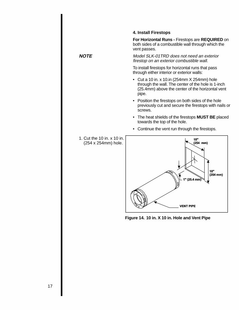
Figure 14. 10 in. X 10 in. Hole and Vent Pipe
4. Install Firestops
For Horizontal Runs - Firestops are REQUIRED onboth sides of a combustible wall through which thevent passes.
NOTE Model SLK-01TRD does not need an exteriorfirestop on an exterior combustible wall.
To install firestops for horizontal runs that passthrough either interior or exterior walls:
• Cut a 10 in. x 10.in (254mm X 254mm) holethrough the wall. The center of the hole is 1-inch(25.4mm) above the center of the horizontal ventpipe.
• Position the firestops on both sides of the holepreviously cut and secure the firestops with nails orscrews.
• The heat shields of the firestops MUST BE placedtowards the top of the hole.
• Continue the vent run through the firestops.
1. Cut the 10 in. x 10 in.(254 x 254mm) hole.

18
1. Position the firestops.
2. Place the heat shieldto the top.
3. Continue the vent run.
Figure 15. Heat Shield, Interior and ExteriorFirestops
For Vertical Runs - One ceiling firestop isREQUIRED at the hole in each ceiling through whichthe vent passes.
To install firestops for vertical runs that pass throughceilings:
• Position a plumb bob directly over the center of thevertical vent component.
• Mark the ceiling to establish the centerpoint of thevent.
• Drill a hole or drive a nail through this centerpoint.
• Check the floor above for any obstructions, such aswiring or plumbing runs.
• Reposition the stove and vent system, if necessary,to accommodate the ceiling joists and/or obstruc-tions.
• Cut an 10” x 10” (254mm X 254mm) hole throughthe ceiling, using the centerpoint previously marked.
• Frame the hole with framing lumber the same sizeas the ceiling joists.
1. Cut the 10” x 10” hole.
2. Add the new framingmembers.
Figure 16. 10” x 10” Hole and New FramingMembers
10 in.(254mm)
10 in.(254mm)

19
If the area above the ceiling is NOT an attic,position and secure the ceiling firestop on theceiling side of the previously cut and framed hole.
This shows a ceilinginstallation.
Figure 17. Ceiling Firestop (Ceiling Side)
If the area above the ceiling IS an attic, position andsecure the firestop on top of the previously framedhole.
This shows an atticinstallation.
1. Keep insulation awayfrom the vent pipe atleast 1 inch (25 mm).
Figure 18. Attic Firestop
C. Vent TerminationFor Horizontal Terminations - To attach andsecure the termination to the last section ofhorizontal vent:
• Rotate and interlock the ends as described atthe beginning of the Installing Vent Componentssection.
• The termination kit should pass through the wallfirestops from the exterior of the building.
• Adjust the termination cap to its final exteriorposition on the building.

20
!WARNING: THE TERMINATION CAPMUST BE POSITIONED SO THAT THEARROW IS POINTING UP.
For roundcap termination kits:
• Use the exterior pipelock hole provided on theround flange of the wall firestop to secure thevent pipe in place.
For trapezoidal cap termination kits:
• Using screws, secure the cap to the exterior wallthrough the flanges built into the cap.
• Use a high-temperature sealant or fiberglassrope gasket to seal between the vent pipe andexterior firestop.
For round captermination:
1. Secure the vent pipe,using the exteriorpipelock hole on theround flange of thewall firestop.
For trapezoidaltermination:
1. Screw the cap to theexterior wall throughthe flanges in the cap.
2. Seal the joint be-tween the pipe andthe exterior firestop.
Figure 19. Round & Trapezoid Termination Caps
WARNING: THE BOTTOM OF THE VENTTERMINATION CAP MUST BE A MINIMUM OF 12INCHES (305MM) ABOVE GROUND LEVEL (GRADE).THE TOP OF THE CAP MUST BE A MINIMUM OF 18INCHES (457MM) BELOW COMBUSTIBLE MATERIAL,SUCH AS A DECK, AND THE SIDE OF THE CAP MUSTBE A MINIMUM OF 6 INCHES (152MM) AWAY FROM APARALLEL OUTSIDE WALL. VENTING TERMINALSSHALL NOT BE RECESSED INTO A WALL OR SIDING.SEE THE FOLLOWING DIAGRAM FOR VENTTERMINATION CLEARANCES.
!

21
CAUTION IF EXTERIOR WALLS ARE FINISHED WITH VINYLSIDING, IT IS NECESSARY TO INSTALL THEVINYL PROTECTOR KIT (VPK-DV) TO THE TOP OFTHE EXTERIOR FIRESTOP (FOR ALL ROUNDTERMINATION CAPS).
V =VENT TERMINAL
X =AIR SUPPLY INLET
12341234123412341234
=AREA WHERE TERMINAL IS NOT PERMITTED
A = 12" clearances above grade, veranda, porch, deck or balcony
B = 12" clearances to window or door that may be opened
C = 9" (U.S.A.) clearance to permanently closed window12" (Canada)
*D = 18" vertical clearance to ventilated soffit located above theterminal within a horizontal distance of 2 feet (60 cm)from the center-line of the terminal
*E = 18" clearance to unventilated soffit
F = 9" clearance to outside corner
G = 6" clearance to inside corner
H = 3 ft. (Canada) not to be installed above a gas meter/regulator assemblywithin 3 feet (90 cm) horizontally from the center-line ofthe regulator
I = 3 ft. (U.S.A.) clearance to service regulator vent outlet6 ft. (Canada)
J = 9" (U.S.A.) clearance to non-mechanical air supply inlet to building12" (Canada) or the combustion air inlet to any other appliance
K = 3 ft. (U.S.A.) clearance to a mechanical air supply inlet6 ft. (Canada)
**L = 7 ft. clearance above paved sidewalk or a paved drivewaylocated on public property
***M = 18" clearance under veranda, porch, deck or balcony
* 30” minimum for vinyl clad soffits.
** a vent shall not terminate directly above a sidewalk or paved driveway which islocated between two single family dwellings and serves both dwellings.
*** only permitted if veranda, porch, deck or balcony is fully open on a minimum of2 sides beneath the floor.
NOTE: Local Codes or Regulations may require different clearances.
Figure 20. Vent Termination Minimum Clearances

22
For Vertical Terminations - To locate the ventand install the vent sections:
• Locate and mark the vent centerpoint on theunderside of the roof, and drive a nail through thecenterpoint.
• Make the outline of the roof hole around thecenterpoint nail.
• The size of the roof hole framing dimensionsdepend on the pitch of the roof. There MUST BEa 1-inch (25.4 mm) clearance from the verticalvent pipe to combustible materials.
• Mark the roof hole accordingly.
• Cover the opening of the installed vent pipes.
• Cut and frame the roof hole.
• Use framing lumber the same size as the roofrafters and install the frame securely. Flashinganchored to the frame must withstand heavywinds.
• Continue to install concentric vent sections upthrough the roof hole (for inside vent installations)or up past the roof line until you reach the appro-priate distance above the roof (for outside termi-nations).
WARNINGMAJOR U.S. BUILDING CODESSPECIFY MINIMUM CHIMNEY AND/ORVENT HEIGHT ABOVE THE ROOF TOP.THESE MINIMUM HEIGHTS ARENECESSARY IN THE INTEREST OFSAFETY. SEE THE FOLLOWINGDIAGRAM FOR MINIMUM HEIGHTS,PROVIDED THE TERMINATION CAP ISAT LEAST TWO (2) FEET FROM AVERTICAL WALL AND 2-FEET BELOW AHORIZONTAL OVERHANG.
NOTE This also pertains to vertical vent systems installedon the outside of the building.
!

23
To seal the roof hole, and to divert rain and snow fromthe vent system:
• Attach a flashing to the roof using nails, and use anon-hardening mastic around the edges of theflashing base where it meets the roof.
• Attach a storm collar over the flashing joint to forma water-tight seal. Place non-hardening masticaround the joint, between the storm collar and thevertical pipe.
• Slide the termination cap over the end of the ventpipe and rotate the pipe clockwise 1/4 turn.
1. Attach the flashingand apply sealantaround the edges ofthe flashing base.
2. Attach the stormcollar over the flash-ing joint and applysealant between thestorm collar andvertical pipe.
Figure 21. Minimum Height from Roof to LowestDischarge Opening
Roof Pitch H (min.) ft.
flat to 6/12 1.06/12 to 7/12 1.25over 7/12 to 8/12 1.5over 8/12 to 9/12 2.0over 9/12 to 10/12 2.5over 10/12 to 11/12 3.25over 11/12 to 12/12 4.0over 12/12 to 14/12 5.0over 14/12 to 16/12 6.0over 16/12 to 18/12 7.0over 18/12 to 20/12 7.5over 20/12 to 21/12 8.0
TERMINATIONCAP

24
WARNING: THIS UNIT IS NOT FOR USE WITH SOLID FUEL.
Standing Pilot Ignition SystemThis system includes millivolt control valve, standing pilot,thermopile/thermocouple flame sensor, and piezo ignitor.
WARNING: 110-120 VAC MUST NEVERBE CONNECTED TO A CONTROL VALVEIN A MILLIVOLT SYSTEM.
Figure 22. Gas Controls Systems
NOTE: Have the gas supply line installed by aqualified service technician in accordance with allbuilding regulations .
NOTE: Before the first firing of the stove, the gassupply line should be purged of any trapped air.
NOTE: Consult local building regulations toproperly size the gas supply line leading to the1/2 inch (13mm) hook-up at the unit.
This gas fireplace is designed to accept a 1/2 inch(13 mm) gas supply line.
To install the gas supply line:• A listed 1/2 inch (13 mm) manual shut-off valve and
a listed flexible gas connector are connected to the1/2 inch (13 mm) inlet of the control valve.
• A 1/8 inch (3 mm) N.P.T. plugged tapping, accessiblefor test gauge connection, should be provided for inthe gas supply line leading to the unit’s shut-off valve.
• Locate the manaul shut-off valve at the rear of the stove.• Connect the gas supply line to the shut-off valve.• When attaching the pipe, support the control so that
the lines are not bent or torn.• After the gas line installation is complete, use a soap
solution to carefully check all gas connections for leaks.
WARNING: DO NOT USE AN OPEN FLAME TO CHECK FOR GAS LEAKS .
!
!
!
Step 4The GasControl System
Step 5The GasSupply Line

25
Step 6Gas PressureRequirements
Pressure requirements for Heat-N-Glo gas stovesare shown in the table below.
Pressure Natural Gas Propane
Minimum 5.0 inches 11.0 inchesInlet Pressure w.c. w.c.
Maximum Inlet 14.0 inches 14.0 inchesGas Pressure w.c. w.c.
Manifold 3.5 inches 10.0 inchesPressure w.c. w.c.
A one-eighth (1/8) inch (3 mm) N.P.T. plugged tappingis provided on the outlet side of the gas control for atest gauge connection to measure the manifoldpressure. To measure inlet pressure, provisions mustbe made to attach a test gauge to a one-eighth (1/8)inch (3 mm) N.P.T. plugged tapping immediatelyupstream of the gas supply connection to thefireplace. On some models there may be a tap for themanifold and inlet pressure on the face of the valve.Use a small flat blade screwdriver to crack open thescrew in the center of the tap. Position a rubber hoseover the tap to obtain the pressure reading.
The fireplace and its individual shut-off valve mustbe disconnected from the gas supply piping systemduring any pressure testing of the system at testpressures in excess of one-half (1/2) psig (3.5 kPa).
The fireplace must be isolated from the gas supplypiping system by closing its individual shut-off valveduring any pressure testing of the gas supply pipingsystem at test pressures equal to or less than one-half (1/2) psig (3.5 kPa).
Figure 23 GAS SUPPLY CONNECTION

26
! WARNING: DO NOT CONNECT 110-120 VACTO THE REMOTE WALL SWITCH OR THECONTROL VALVE WILL BE DESTROYED.
CAUTION LABEL ALL WIRES PRIOR TO DISCONNECTION WHENSERVICING CONTROLS. WIRING ERRORS CANCAUSE IMPROPER AND DANGEROUS OPERATION.VERIFY PROPER OPERATION AFTER SERVICING.
Figure 24. Standing Pilot Ignition Wiring Diagram
!
Step 7Wiring theStove
NOTE: Electrical wiring must be installed by acompetent electrician.For Standing Pilot Ignition WiringAppliance Requirements• This appliance DOES NOT require 110-120 VAC
to operate.WARNING: DO NOT CONNECT 110-120VAC TO THE GAS CONTROL VALVE ORTHE APPLIANCE WILL MALFUNCTIONAND THE VALVE WILL BE DESTROYED .
Optional AccessoriesOptional fan and remote control kits require that 110-120 VAC be wired to the factory installed junctionbox before the stove is permanently installed.
Remote Wall SwitchPosition the remote wall switch in the desiredposition on a wall. Run a maximum of 25 feet (7.8m)or less length of 18 A.W.G. minimum wire andconnect it to the stove ON/OFF switch pigtails.
Figure 25. Fan Wiring Diagram (when fitted)

27
1. Place the embermaterial directlyonto the top of theburner.
Positioning the LogsIf the gas logs have been factory installed they shouldnot need to be positioned.
If the logs have been packaged separately, refer to theinstallation instructions that accompany the logs.Save the log instructions with this manual.
If sooting occurs, the logs might need to be repositionedslightly to avoid excessive flame impingement.Placing the Ember MaterialTwo separate bags of ember material are shipped withthis gas fireplace:• The bag labeled Golden Ember (GE-93) is flame
colorant material.• The bag labeled Glowing Ember (050-721) is
standard glowing ember material.To place the ember material:• Remove the glass door from the unit.• Cover the top of the burner with a single layer of em-
ber material. Then sprinkle GE-93 on top of the burner.• Save the remaining ember materials for use during
fireplace servicing.• Replace the glass door and a front trim door on the
unit (see Replacement Parts Section of the manual.)
Step 9Installing Logsand EmberMaterial
WARNING: WHEN FINISHING THE STOVE,NEVER OBSTRUCT OR MODIFY THE AIRINLET/OUTLET GRILLES IN ANY MANNER.
!Step 8Finishing
Figure 26. Combustible Mantel Minimum
Do not install combustiblemantel or other combustibleprojection closer than 55inches minimum above thetop of the unit.
HEARTH EXTENSIONWhile a hearth extensionmay be desireable foraesthetic reasons, it is notrequired for gas fireplaceheaters per ANSI or CSAtesting standards.
Figure 27. Placement of the Ember Material

28
Step 10Before Lightingthe Stove
Before lighting the stove, be sure to do the following:
Review safety warnings and cautions
• Read the Safety and Warning Information sectionat the beginning of this Installers Guide.
Double-check for gas leaks
• Before lighting the stove, double-check the unit forpossible gas leaks.
Double-check vent terminations for obstruc-tions.
• Before lighting the stove, double-check the unit forpossible obstructions that could be blocking thevent terminations.
Double-check for faulty components
• Any component that is found to be faulty MUST BEreplaced with an approved component. Tamperingwith the stove components is DANGEROUS andvoids all warranties.
A small amount of air will be in the gas supply lines.When first lighting the stove, it will take a few minutesfor the lines to purge themselves of this air. Once thepurging is complete, the stove will light and willoperate normally.
Subsequent lightings of the stove will not require thispurging of air from the gas supply lines, unless thegas valve has been turned to the OFF position , inwhich case the air would have to be purged.
Step 11Lighting theStove
You’ve reviewed all safety warnings, you’ve checkedthe stove for gas leaks, you know the vent system isunobstructed, and you’ve checked for faultycomponents. Now you’re ready to light the stove.
WARNINGPLEASE REFER TO THE USER’SMANUAL FOR ALL CAUTIONS, SAFETY,AND WARNING INFORMATIONPERTAINING TO THE LIGHTING ANDOPERATION OF THE STOVE.
After theInstallation
LEAVE THIS INSTALLATION MANUALWITH THE APPLIANCE FOR FUTUREREFERENCE.
!
!

29
4MaintainingandServicingYour Stove
StoveMaintenance
Although the frequency of your stove servicing andmaintenance will depend on use and the type ofinstallation, you should have a qualified servicetechnician perform an appliance check-up at thebeginning of each heating season. See the tablebelow for specific guidelines regarding each stovemaintenance task.
IMPORTANT TURN OFF THE GAS BEFORE SERVICING YOURSTOVE.
Type ofStove Stove Maintenance Task To
Maintenance Frequency By Be Completed
Replacing Once annually, Qualified Brush away loose ember material nearOld Ember during the Service the burner. Replace old ember materialMaterial annual check-up Technician with new dime-size and shape pieces
of Golden Ember (GE-93) and GlowingEmber (050-721). New ember materialshould be placed alternately on top of theburner—a layer of Golden Ember, a layerof Glowing Ember, and so on. Save theremaining ember material and repeat thisprocedure at your next servicing. Formore information, see Placing EmberMaterial in the INSTALLERS GUIDE.
Cleaning Once annually Qualified Brush or vacuum the controlBurner Service compartment, stove logs, and& Controls Technician burner areas surrounding the logs.
Checking Periodically Qualified Make a visual check of your stove’sFlame Service flame patterns. Make sure the flamesPatterns , Technician/ are steady—not lifting or floating. SeeFlame Height Owner the picture in Figure 28. The thermopile/
thermocouple tips should be coveredwith flame. See the picture in Figure 29.
Checking Before initial use Qualified Inspect the external terminal cap on aVent System and at least Service regular basis to ensure that no debris is
annually thereafter, Technician/ interfering with the flow of air. Inspectmore frequently Owner entire vent system for proper function.if possible
Cleaning As necessary Homeowner Clean as necessary, particularly afterGlass Door adding new ember (flame colorant)
material. Film deposits on the inside ofthe glass door should be cleaned offusing a household glass cleaner.NOTE: DO NOT handle or attempt toclean the door when it is hot andDO NOT use abrasive cleaners.

30
Figure 28. Burner Flame Patterns
MAKE SURE THE FLAMESARE STEADY—NOTLIFTING OR FLOATING.
Figure 29. Pilot Flame Patterns
31
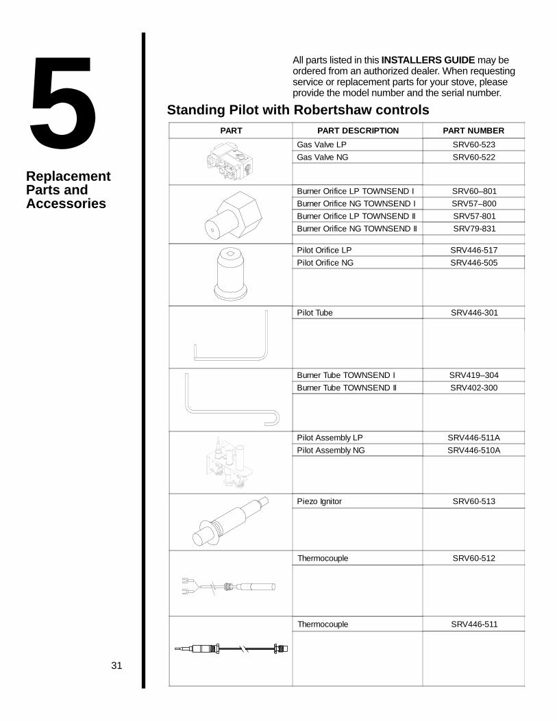
All parts listed in this INSTALLERS GUIDE may beordered from an authorized dealer. When requestingservice or replacement parts for your stove, pleaseprovide the model number and the serial number.
Standing Pilot with Robertshaw controlsPART PART DESCRIPTION PART NUMBER
Gas Valve LP SRV60-523
Gas Valve NG SRV60-522
Burner Orifice LP TOWNSEND I SRV60–801
Burner Orifice NG TOWNSEND I SRV57–800
Burner Orifice LP TOWNSEND II SRV57-801
Burner Orifice NG TOWNSEND II SRV79-831
Pilot Orifice LP SRV446-517
Pilot Orifice NG SRV446-505
Pilot Tube SRV446-301
Burner Tube TOWNSEND I SRV419–304
Burner Tube TOWNSEND II SRV402-300
Pilot Assembly LP SRV446-511A
Pilot Assembly NG SRV446-510A
Piezo Ignitor SRV60-513
Thermocouple SRV60-512
Thermocouple SRV446-511
5ReplacementParts andAccessories

32
Standing Pilot with S.I.T. controls only
PART PART DESCRIPTION PART NUMBER
Piezo Ignitor SRV60-513
Thermopile SRV60-512
Thermocouple SRV571-511
Valve LP SRV571-501Valve NG SRV571-500
Burner Tube Townsend I SRV419-304Burner Tube Townsend II SRV402-300
Pilot Tube SRV571-301
Pilot Orifice LP SRV571-517Pilot Orifice NG SRV571-516
Pilot Assembly LP SRV571-511APilot Assembly NG SRV571-510A

33
Both Robertshaw & S.I.T. Standing Pilot Replacement Parts
Glass Specifications: Townsend I 13 3/8” x 14” CeramicTownsend II 14 3/4” x 21 1/2” Ceramic
PART PART DESCRIPTION PART NUMBER
Burner LP/NG Townsend I SRV419-327A
Burner LP Townsend II SRV402-175A
Burner NG Townsend II SRV402-181A
Flat Head Screw Townsend I SRV402-800
Flat Head Screw Townsend II SRV402-802
On/Off Rocker Switch SRV60–525A
Glass Assembly - TOWNSEND I SRV419-600A
Glass Assembly - TOWNSEND II SRV402-600A
3/16" Allen Wrench SRV402-801

34
Both Robertshaw & S.I.T. Replacement PartsPART PART DESCRIPTION PART NUMBER
Upper Front Log - TOWNSEND I SRV446-715
Left Front Log - TOWNSEND I SRV446-703
Rear Log - TOWNSEND II SRV446-701
Front Log - TOWNSEND II SRV446-704
Right Front Log - TOWNSEND IRight Middle Log - TOWNSEND II
SRV446-714
Left Middle Log - TOWNSEND II SRV446-702
Top Log - TOWNSEND II SRV402-701
Rear Log - TOWNSEND I SRV419-705

35
AccessoriesACCESSORY PART DESCRIPTION PART NUMBER
Fan Kit GFK-160A
GFK-230
Remote Control Kit RC-SMART
SMART-STAT
RC-MLT
Wall Switch Kit
- Off White WSK-21
- White WSK-21-W