
Hawk 1000 - Cleaver-Brookscleaverbrooks.com/docs/manuals/750-366-Hawk1000.pdf · 2019-05-03 · The...
104
750-366 01/2019 Hawk 1000 Boiler Control Operation Manual
Transcript of Hawk 1000 - Cleaver-Brookscleaverbrooks.com/docs/manuals/750-366-Hawk1000.pdf · 2019-05-03 · The...
750-36601/2019
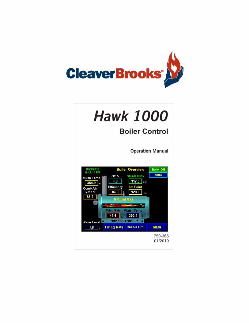
Hawk 1000Boiler Control
Operation Manual

TO: Owners, Operators and/or Maintenance Personnel
This operating manual presents information that will help to properly operate and care for the equipment. Study its con-tents carefully. The unit will provide good service and continued operation if proper operating and maintenance instruc-tions are followed. No attempt should be made to operate the unit until the principles of operation and all of the components are thoroughly understood.
It is the responsibility of the owner to train and advise not only his or her personnel, but the contractors' personnel who are servicing, repairing, or operating the equipment, in all safety aspects.
Cleaver-Brooks equipment is designed and engineered to give long life and excellent service on the job. The electrical and mechanical devices supplied as part of the unit were chosen because of their known ability to perform; however, proper operating techniques and maintenance procedures must be followed at all times.
Any "automatic" features included in the design do not relieve the attendant of any responsibility. Such features merely free him of certain repetitive chores and give him more time to devote to the proper upkeep of equipment.
It is solely the operator’s responsibility to properly operate and maintain the equipment. No amount of written instruc-tions can replace intelligent thinking and reasoning and this manual is not intended to relieve the operating personnel of the responsibility for proper operation. On the other hand, a thorough understanding of this manual is required before attempting to operate, maintain, service, or repair this equipment.
Operating controls will normally function for long periods of time and we have found that some operators become lax in their daily or monthly testing, assuming that normal operation will continue indefinitely. Malfunctions of controls lead to uneconomical operation and damage and, in most cases, these conditions can be traced directly to carelessness and deficiencies in testing and maintenance.
The operation of this equipment by the owner and his operating personnel must comply with all requirements or regula-tions of his insurance company and/or other authority having jurisdiction. In the event of any conflict or inconsistency between such requirements and the warnings or instructions contained herein, please contact Cleaver-Brooks before pro-ceeding.

Cleaver-BrooksHAWK 1000 Boiler Control
Operation Manual
Manual Part No. 750-36601/2019
Please direct purchase orders for replacement manuals to your local Cleaver-Brooks authorized representative


CONTENTSSection 1General
Introduction ............................................................................................... 1-2System Description ..................................................................................... 1-3Hawk 1000 System Features ....................................................................... 1-4Program Numbers ....................................................................................... 1-4Safety Provisions and Diagnostics ................................................................. 1-5Inputs and Outputs...................................................................................... 1-6
Section 2System Components
Overview ...................................................................................................2-2Controller ..................................................................................................2-2Human-Machine Interface (HMI) .................................................................2-3Communications ........................................................................................2-4Sensor Inputs ............................................................................................2-6
Section 3Hardware Checkout
Control Panel ..............................................................................................3-2Modbus Actuators ......................................................................................3-7
Section 4System Configuration
Introduction ............................................................................................. 4-2Main Menu .............................................................................................. 4-3Boiler Overview ........................................................................................ 4-4System Configuration ................................................................................ 4-5Email Setup.............................................................................................. 4-25PanelView Plus Setup ................................................................................ 4-26Remote Monitoring .................................................................................... 4-34
Section 5Commissioning
Commissioning the Actuators . . . . . . . . . . . . . . . . . . . . . . . . . . . . . . . . . . . .5-2Setting Combustion - Parallel Positioning . . . . . . . . . . . . . . . . . . . . . . . . . . . .5-4Setting Combustion - Single Point Positioning . . . . . . . . . . . . . . . . . . . . . . . . .5-7Setting Combustion - Low/High/Low . . . . . . . . . . . . . . . . . . . . . . . . . . . . . . .5-7Firing Rate Screen . . . . . . . . . . . . . . . . . . . . . . . . . . . . . . . . . . . . . . . . . . .5-8Alarms and Limits . . . . . . . . . . . . . . . . . . . . . . . . . . . . . . . . . . . . . . . . . . .5-11Setpoints . . . . . . . . . . . . . . . . . . . . . . . . . . . . . . . . . . . . . . . . . . . . . . . . . .5-13O2 Trim . . . . . . . . . . . . . . . . . . . . . . . . . . . . . . . . . . . . . . . . . . . . . . . . . .5-15Drive Data . . . . . . . . . . . . . . . . . . . . . . . . . . . . . . . . . . . . . . . . . . . . . . . . .5-16Ethernet Configuration . . . . . . . . . . . . . . . . . . . . . . . . . . . . . . . . . . . . . . . .5-16Two Boiler Lead Lag. . . . . . . . . . . . . . . . . . . . . . . . . . . . . . . . . . . . . . . . . 5-17Thermal Shock Routine. . . . . . . . . . . . . . . . . . . . . . . . . . . . . . . . . . . . . . . 5-20
Section 6Diagnostics and Troubleshooting
System Monitoring and Diagnostics . . . . . . . . . . . . . . . . . . . . . . . . . . . . . . .6-2Alarms . . . . . . . . . . . . . . . . . . . . . . . . . . . . . . . . . . . . . . . . . . . . . . . . . . . .6-5PLC Status . . . . . . . . . . . . . . . . . . . . . . . . . . . . . . . . . . . . . . . . . . . . . . . . .6-9
Section 7Parts
Hawk 1000 Parts List . . . . . . . . . . . . . . . . . . . . . . . . . . . . . . . . . . . . . . . . .7-1
APPENDIX A Tag ListAPPENDIX B Loading a PLC Program


www.cleaverbrooks.com
Section 1General
Introduction . . . . . . . . . . . . . . . . . . . . . . . . . . . . . . . . . . . . . . . . . . . . . . . . 1-2System Description . . . . . . . . . . . . . . . . . . . . . . . . . . . . . . . . . . . . . . . . . . . 1-3Hawk 1000 System Features . . . . . . . . . . . . . . . . . . . . . . . . . . . . . . . . . . . . 1-4Program Numbers . . . . . . . . . . . . . . . . . . . . . . . . . . . . . . . . . . . . . . . . . . . . 1-4Safety Provisions and Diagnostics . . . . . . . . . . . . . . . . . . . . . . . . . . . . . . . . . 1-5
Burner Management . . . . . . . . . . . . . . . . . . . . . . . . . . . . . . . . . . . 1-5Boiler Controls . . . . . . . . . . . . . . . . . . . . . . . . . . . . . . . . . . . . . . . . 1-5
Inputs and Outputs. . . . . . . . . . . . . . . . . . . . . . . . . . . . . . . . . . . . . . . . . . . . 1-6
Section 1 — General Hawk 1000
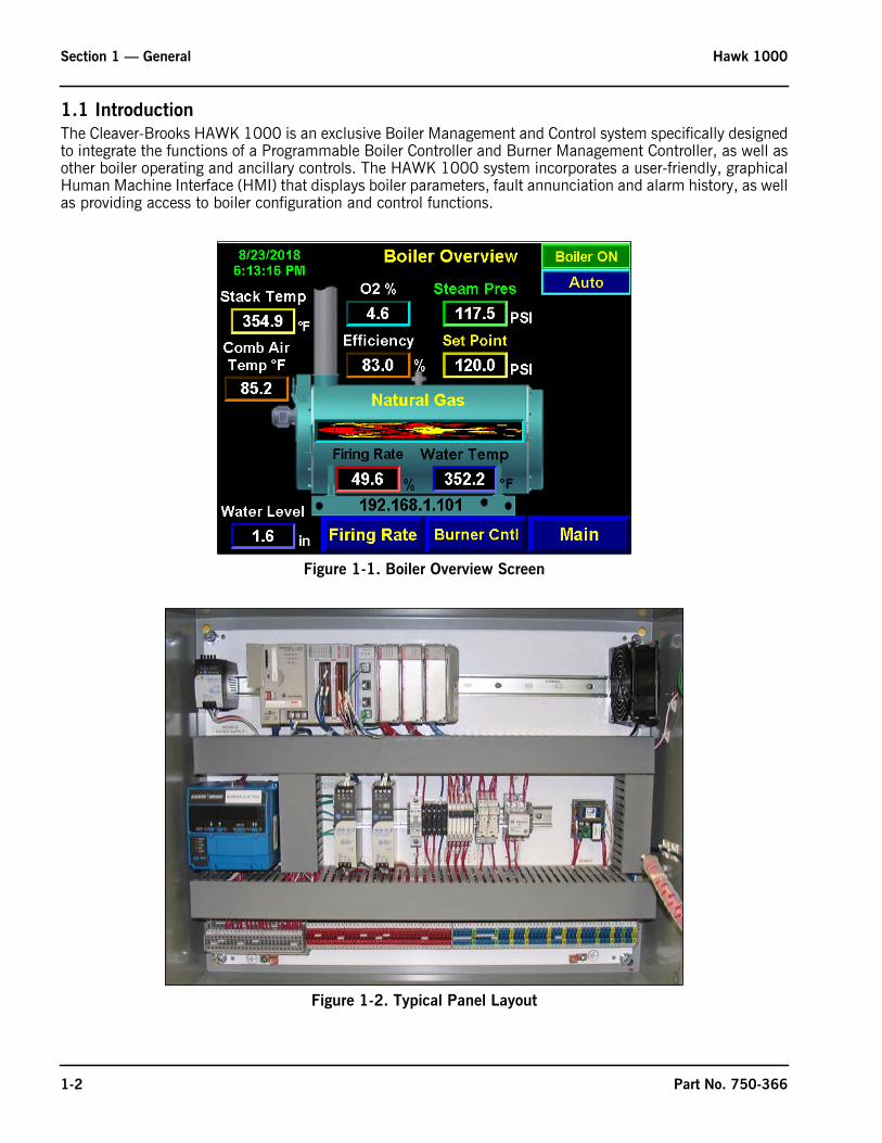
1.1 IntroductionThe Cleaver-Brooks HAWK 1000 is an exclusive Boiler Management and Control system specifically designedto integrate the functions of a Programmable Boiler Controller and Burner Management Controller, as well asother boiler operating and ancillary controls. The HAWK 1000 system incorporates a user-friendly, graphicalHuman Machine Interface (HMI) that displays boiler parameters, fault annunciation and alarm history, as wellas providing access to boiler configuration and control functions.
Figure 1-1. Boiler Overview Screen
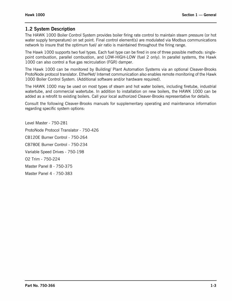
Figure 1-2. Typical Panel Layout
1-2 Part No. 750-366
Hawk 1000 Section 1 — General
1.2 System DescriptionThe HAWK 1000 Boiler Control System provides boiler firing rate control to maintain steam pressure (or hotwater supply temperature) on set point. Final control element(s) are modulated via Modbus communicationsnetwork to insure that the optimum fuel/ air ratio is maintained throughout the firing range.
The Hawk 1000 supports two fuel types. Each fuel type can be fired in one of three possible methods: single-point combustion, parallel combustion, and LOW-HIGH-LOW (fuel 2 only). In parallel systems, the Hawk1000 can also control a flue gas recirculation (FGR) damper.
The Hawk 1000 can be monitored by Building/ Plant Automation Systems via an optional Cleaver-BrooksProtoNode protocol translator. EtherNet/ Internet communication also enables remote monitoring of the Hawk1000 Boiler Control System. (Additional software and/or hardware required).
The HAWK 1000 may be used on most types of steam and hot water boilers, including firetube, industrialwatertube, and commercial watertube. In addition to installation on new boilers, the HAWK 1000 can beadded as a retrofit to existing boilers. Call your local authorized Cleaver-Brooks representative for details.
Consult the following Cleaver-Brooks manuals for supplementary operating and maintenance informationregarding specific system options:
Level Master - 750-281
ProtoNode Protocol Translator - 750-426
CB120E Burner Control - 750-264
CB780E Burner Control - 750-234
Variable Speed Drives - 750-198
O2 Trim - 750-224
Master Panel 8 - 750-375
Master Panel 4 - 750-383
Part No. 750-366 1-3

Section 1 — General Hawk 1000
1.3 Hawk 1000 System Features• Burner Control controls burner start and shutdown sequencing and flame and interlock monitoring• Compatible with CB780E and CB120E Burner Controls and Flame Scanners• Boiler Control monitors and displays connected boiler parameters (operating pressure or temperature, stack
temperature, shell water temperature, O2% etc.)• 6” color touch/keypad Human Machine Interface (HMI)• Optimized boiler firing rate control• Alarm/Fault Indication and History -- first out annunciation with time stamp and displayed in order of fault occurrence• Dual set point capability• Thermal shock protection (includes warm-up routine, low fire hold & hot stand-by operation)• Available input for any ONE of the following: remote modulation, remote set point, or Level Master water level interface• Available input for any ONE of the following: water temp (Steam)• Return Temp or Outdoor reset (hot water boilers)• Remote Modulation by communications (EtherNet)• Remote Set Point by communications (EtherNet)• Boiler efficiency calculation• Assured Low Fire Cut Off• External Interlock with auxiliary devices (fresh air damper/louvers, circulating pumps, etc.)• High stack temperature alarm and shutdown• Built-in two-boiler lead/lag capability• EtherNet communications• Three firing modes: Single-point, parallel, or LOW-HIGH-LOW on Fuel 2• Revert to Pilot control function (requires CB120E burner control)• Supports control of a flue gas recirculation (FGR) damper• Supports the control of a 2nd gaseous fuel actuator (Both Gaseous Fuels)• OPC server software for building/plant automation system interface• Remote monitoring software• O2 monitoring and O2 trim (Option)• Variable Speed Drive on combustion air fan (with bypass) (Option)• Combustion Air Temperature Monitoring (Option)• Email and text messaging for alarms/faults• Force Hot Standby by HMI
1.4 Program NumbersHawk 1000 PLC and HMI programs can be identified by the following program numbers:
PLC Standard Program: 98500509_001_xxxPLC Standard Metric Program: 98500509_001_xxx_Metric6” HMI Program: 98500670_xxx6” HMI Metric Program: 98500695_xxx
1-4 Part No. 750-366

Hawk 1000 Section 1 — General
1.5 Safety Provisions and Diagnostics1.5.1 Burner Management
• Utilizes CB780E or CB120E Burner Control• Communicates with the PLC via Modbus• Burner Control Status, Faults and Diagnostics displayed on HMI or panel mounted burner control• Flame condition monitoring using either IR or UV Flame Scanner
1.5.2 Boiler Controls• Operating and Modulating Controls• Monitors Low Water Cut-Off• Monitors Burner Control alarm terminal• Non-Recycle Limit Relay de-energizes on PLC system errors or faults• Transmitter input signal out of range alarms• Actuator Modbus communication fault diagnostics• Password protected system configuration and system set up screens• Alarm Management incorporated into door-mounted HMI• Password protection of Programmable Controller Logic• Optional Variable Frequency Drive (VFD) fault shutdown
Figure 1-3. FSG / Burner Control screen
CB780E
CB120E
Part No. 750-366 1-5

Section 1 — General Hawk 1000
1-6 Part No. 750-366
1.6 Inputs and Outputs
Processor 1769-L24ER-QBFC1B - Slot 0Embedded I/O - Slot 1-3
Dig IN Dig OUT Anlg IN Anlg OutHigh Limit Control I1/0ALWCO I1/1Low Fuel 1 Pressure/Low Oil Temp I1/2High Fuel 1 Pressure/High Oil Temp I1/3Low Fuel 2 Pressure I1/4High Fuel 2 Pressure I1/5Oil Drawer Switch I1/6Atomizing Air Pressure Low I1/7Combustion Air Pressure Low I1/8High Water (ST) or Flow Sw. (HW) I1/9VSD Bypass I1/10Combustion Air Pressure High I1/11Spare I1/12Auxiliary Alarm 1 I1/13Auxiliary Alarm 2 I1/14Auxiliary Alarm 3 I1/152 Boiler Lead Lag Master Start Slave Boiler O1/0Ready for Lead/Lag O1/1To Stand Alone Draft O1/2Spare(s) O1/3-O1/15Steam Pres (ST) / Supply Temp (HW) I2/0Stack Temp I2/1Water Temp (ST) / Outdoor Temp (HW) / Return Temp (HW) I2/2Water Level (ST) / Rem Mod / Rem Set Point I2/3VSDControl O2/0Firing Rate or Two Boiler Llag Control O2/1High Speed Counter (NOT USED) Slot 3
Slot 4 Slot 5 Slot 6 Slot 7SM2
ModbusModule
Slot 4
I5/0 Blower Terminal O6/0 Recycle Limit (RLR) I7/0 VSD FeedbackI5/1 Purge O6/1 Start Ext. Device (FAD) I7/1 O2 SignalI5/2 O2 Analyzer Status (Yokogawa) O6/2 Non-Recycle Limit (NRLR) I7/2 Comb Air TempI5/3 VSD Status O6/3 Prove Low Fire I7/3 Common Header Press (ST) Temp (HW)I5/4 Force to Low Fire O6/4 Revert To Pilot (Fireye CB120E only) I5/5 Ready To Start/ Limits Closed O6/5 Prove High Fire / Open High Fire Oil Valve 2I5/6 Ext. Device Start Interlock (FAD) O6/6 Alarm BellI5/7 ALFCO O6/7 Open High Fire Oil Valve 1I5/8 Pilot TerminalI5/9 Main Fuel Terminal
I5/10 Fuel 1 SelectedI5/11 Fuel 2 SelectedI5/12 Burner Control Alarm TerminalI5/13 Low Water AlarmI5/14 Slave Boiler Available/ Sel Rem Mod / Sel Set PointI5/15 Burner Switch

www.cleaverbrooks.com
Section 2System Components
Overview . . . . . . . . . . . . . . . . . . . . . . . . . . . . . . . . . . . . . . . . . . . . . . . . . . 2-2Base Unit . . . . . . . . . . . . . . . . . . . . . . . . . . . . . . . . . . . . . . . . . . . . . . . . . . 2-2Human-Machine Interface (HMI) . . . . . . . . . . . . . . . . . . . . . . . . . . . . . . . . . . 2-3Communications . . . . . . . . . . . . . . . . . . . . . . . . . . . . . . . . . . . . . . . . . . . . . 2-4
Modbus . . . . . . . . . . . . . . . . . . . . . . . . . . . . . . . . . . . . . . . . . . . . 2-4Ethernet . . . . . . . . . . . . . . . . . . . . . . . . . . . . . . . . . . . . . . . . . . . . 2-5USB . . . . . . . . . . . . . . . . . . . . . . . . . . . . . . . . . . . . . . . . . . . . . . 2-5
Sensor Inputs . . . . . . . . . . . . . . . . . . . . . . . . . . . . . . . . . . . . . . . . . . . . . . . 2-6Steam Systems: . . . . . . . . . . . . . . . . . . . . . . . . . . . . . . . . . . . . . . 2-6Hot Water systems: . . . . . . . . . . . . . . . . . . . . . . . . . . . . . . . . . . . . 2-6

Section 2 — System Components Hawk 1000
2-2
2.1 OverviewThe principal components of the HAWK 1000 Boiler Control System are the Programmable Logic Controller (PLC), Touch Screen Human Machine Interface (HMI), and the Flame Safety Control. The system also includes 24VDC power supplies and various relays and circuit breakers.
1. Base Unit1a. L24ER Programmable Logic Controller (PLC)1b. Embedded I/O
2. SM2 Modbus Communications Module3. Digital Inputs4. Digital Outputs5. Analog Inputs (optional)6. Burner Control7. Power supplies8. Circuit breakers, relays, fuses, etc.9. ALWCO control
The HAWK 1000 Boiler Controller is factory pre-programmed to work with most Cleaver-Brooks firetube and watertube boilers, yet allows easy configuration for specific boiler applications. The Boiler Controller program logic is password secured, ensuring tamper- proof controller operation. The Touch Screen HMI provides user- friendly access to firing rate control functions, boiler diagnostics and alarm history, as well as connected operating parameters. Burner management is handled by the proven CB780E or optional CB120E Flame Safety Control.
2.2 Base UnitThe Base Unit consists of the Processor (CPU) which holds the program logic and configuration for the boiler controller and embedded I/O modules which consist of discrete inputs, discrete outputs, and analog inputs. The program logic is password-secured at the factory.
The SM2 module handles the Modbus communications between the PLC and other devices.
Figure 2-1. Hawk 1000 Panel
1b 2 3 5
6 86
1
1a
7
9
4
Part No. 750-366

Hawk 1000 Section 2 — System Components
The Module Power Supply powers the Base Unit and the I/O modules. The remainder of the PLC rack is for the discrete input and output modules, and for analog input module (optional).
I/O modules are used to send and receive control and communication signals to/from other parts of the system.
A Right End Cap Terminator is required to complete the modular communication bus. It attaches to the right side of the last module in the rack.
An optional analog input module can be added to the PLC to provide additional functionality.
NOTE: The PLC program expects each device to be in a specific slot location. The HAWK 1000 controls will not function unless all devices are properly installed and configured.
2.3 Human-Machine Interface (HMI)
The HMI displays numerous boiler parameters at a glance and provides easy menu navigation for configuring system parameters, setting of combustion, monitoring the boiler processes, and managing and annunciating system alarms.
The HMI communicates with the PLC via Ethernet and is powered by a 24VDC din-rail mounted power supply.
DISCRETE and ANALOG Signal TypesDiscrete inputs/outputs are used for signals taking on only one of two possible states (on/off, open/close, etc.). The input state is represented by a bit (0 or 1) in the control logic. Example:
Boiler Ready (yes/no)Analog signals can assume almost infinite values within the fixed analog input/ output current range of 4-20 mA. The Hawk 1000 PLC converts this current value to a range in engineering units. Example:
Steam Pressure (0-150 PSI)
Slot Module
1769-L24ER-QBFC1B Processor0
1
2
3
4
5
6
7
Embedded Discrete Inputs/Outputs
Embedded Analog Inputs/Outputs
Embedded High Speed Counter
SM2 Modbus Module
Digital Input Module
Relay Output Module
Analog Input Module (4 ch. - optional)
BASEUNIT
SD CARDSLOT
ETHERNET
POWER
BATTERY
USBDEVICE PORT
USBHOST PORT
Figure 2-2. PanelView connections
Part No. 750-366 2-3
Section 2 — System Components Hawk 1000
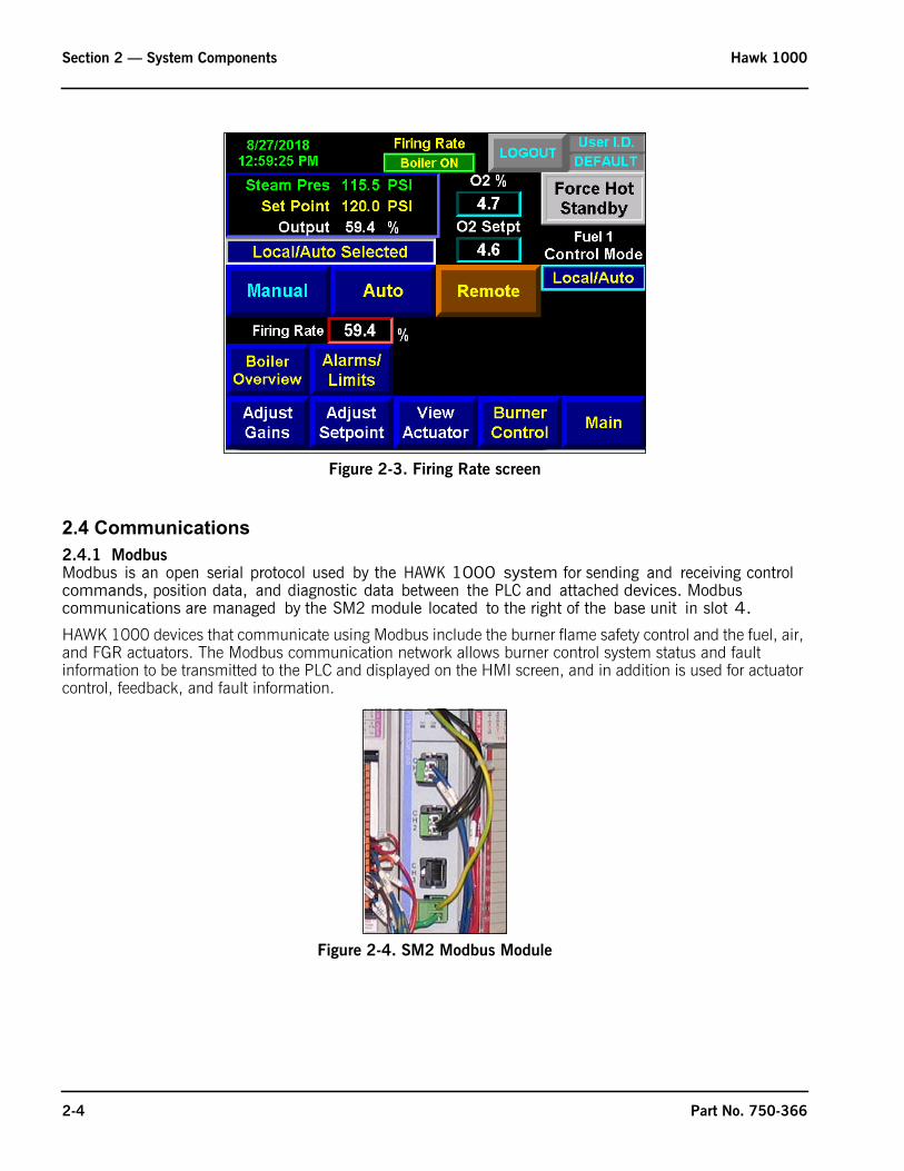
2.4 Communications2.4.1 ModbusModbus is an open serial protocol used by the HAWK 1000 system for sending and receiving control commands, position data, and diagnostic data between the PLC and attached devices. Modbus communications are managed by the SM2 module located to the right of the base unit in slot 4.
HAWK 1000 devices that communicate using Modbus include the burner flame safety control and the fuel, air, and FGR actuators. The Modbus communication network allows burner control system status and fault information to be transmitted to the PLC and displayed on the HMI screen, and in addition is used for actuator control, feedback, and fault information.
Figure 2-3. Firing Rate screen
Figure 2-4. SM2 Modbus Module
2-4 Part No. 750-366

Hawk 1000 Section 2 — System Components
2.4.2 EthernetThe HAWK 1000 uses Ethernet for several communication functions:
• Communication between the PLC and HMI. The Ethernet cable connecting the PLC and HMI can be either a straight through or a crossover type.
• Connection of the boiler control system to an existing infrastructure, i.e. plant Local Area Network (LAN)
• Integration with a Building/Plant Automation System (BAS)
• Remote monitoring of boiler control system via the customer's Wide Area Network (WAN) or via the Internet
• Connection of a laptop for diagnostics
• Email or texting of boiler alarms to plant or service personnel
Ethernet/IP is also used for control functions. Individual boiler controllers may be networked to facilitate lead/lag control, with a single BAS interface for multiple boiler systems.
• Networking multiple boiler controllers with a single BAS interface• Writing remote setpoint or remote start/stop of boiler• Writing remote firing rate of boiler• Networking two boiler controllers with Cleaver Brooks two boiler lead lag• Networking multiple boiler controllers with a Cleaver-Brooks Master Panel
2.4.3 USBUSB communications are used to connect a laptop computer for diagnostic purposes.
The HMI has 2 USB ports that may be used for file transfer. The HMI USB ports also support keyboard and mouse input.
Figure 2-5. L24ER Communication Ports
Ethernet ports (bottom of Base Unit)
PORT 1
PORT 2
0 1 2 3 4 5 6 7
8 9 10 11 12 13 14 15
0 1 2 3 4 5 6 7
8 9 10
A0 B0 Z0
A1 B1 Z1
0 2 FUSE
1 3 OK11 12 13 14 15
HIG
H S
PEED
COU
NTE
R
INO
UT
DC
INPU
T
24VD
CSI
NK\
SOU
RCE
24VD
CSO
URC
E
OU
TPU
TD
C
+24VDC COM FG
0 1 2 3 4 5 6 7
8 9 10 11 12 13 14 15
0 1 2 3 4 5 6 7
8 9 10
A0 B0 Z0
A1 B1 Z1
0 2 FUSE
1 3 OK11 12 13 14 15
HIG
H S
PEED
COU
NTE
R
INO
UT
DC
INPU
T
24VD
CSI
NK\
SOU
RCE
24VD
CSO
URC
E
OU
TPU
TD
C
+24VDC COM FG
00
01
02
03
04
05
06
07
NC
+V
00
01
02
03
04
05
06
07
COM0
COM0
08
09
10
11
12
13
14
15
NC
+V
08
09
10
11
12
13
14
15
COM1
COM1
A0+
B0+
Z0+
A1+
B1+
Z1+
+V
OUT1
OUT0
COM COM
A0-
B0-
Z0-
A1-
B1-
Z1-
+V
0UT3
Vin0+
Vin2+
VOUT0+I
OUT0+
VOUT1+
Iin3+
Vin1+Iin1+
Iin1+
Vin3+
CJC-
CJC+
V/Iin1-
V/Iin3-
V/Iin0-
V/Iin2-
Iin0+
Iin2+
OUT2
COMCOM
DC IN HSC
DC OUT ANALOG
00:00:BC:2E:69:F6
L24ER
QBFC1B
USBPORT
Part No. 750-366 2-5

Section 2 — System Components Hawk 1000
2.5 Sensor InputsThe following table shows the sensors available as standard and as options for steam systems (ST) and for hot water (HW) systems:
All systems use RTDs with a transmitter to produce 4-20mA output for temperature detection.
2.5.1 Steam Systems:
Steam Pressure is the primary sensor input to the HAWK 1000 Controller in a Steam System. It transmits a 4-20mA process variable signal to the Controller that is used to control Firing Rate and the Operating Limit Control.
Stack Flue Gas Temperature is used for High Stack Temperature alarms and shutdown. It is also used in the boiler efficiency calculation.
Water Temperature (mandatory on steam boilers) measures boiler-shell water temperature and is used for thermal shock protection and hot standby control on steam boilers. The standard location for the thermowell is a 1/2” NPT coupling at the right-hand side center-line of the boiler shell. If this location is not available, an unused feedwater connection may be used.
Water Level sensor is OPTIONAL on steam boilers, but must be a CB Level Master.
Steam Header Pressure sensor is optional on steam boilers configured as two boiler Lead Lag master.
2.5.2 Hot Water systems:
Supply Temperature is the primary sensor input to the HAWK 1000 Controller in a Hot Water system. It transmits a 4-20mA process variable signal to the Controller that is used to control Firing Rate and the Operating Limit Control.
Outdoor Temperature is used in Hot Water Systems with the Outdoor Temperature Reset Option.
Return Temperature is used in Hot Water Systems with the Return Temperature option and is monitor only.
Header Water Temperature sensor is optional on steam boilers configured as two boiler Lead Lag master.
NOTE: The Outdoor Temperature and Return Temperature sensors use the same input. One or the other can be used with the Hawk 1000, but not both.
Sensor System Standard OptionalSteam Pressure ST YesStack Temperature ST & HW YesWater Temperature ST YesWater Level ST YesSupply Temperature HW YesOutdoor Temperature HW YesReturn Temperature HW YesComb. Air Temperature ST & HW YesSteam Header Pressure for Two Boiler Lead Lag Master ST YesHeader Water Temp for Two Boiler Lead Lag Master HW Yes
2-6 Part No. 750-366

www.cleaverbrooks.com
Section 3Hardware Checkout
Control Panel . . . . . . . . . . . . . . . . . . . . . . . . . . . . . . . . . . . . . . . . . . . . . 3-2DIN Rail Latch and Expansion I/O Module Locking Levers . . . . . . 3-2Panel and Field Wiring Terminations . . . . . . . . . . . . . . . . . . . . . 3-3SM2 Module DIP Switch . . . . . . . . . . . . . . . . . . . . . . . . . . . . . 3-3Burner Control Modbus Address and Baud Rate - CB780E . . . . . 3-4Burner Control Modbus Address and Baud Rate - CB120E . . . . . 3-6PLC Switch . . . . . . . . . . . . . . . . . . . . . . . . . . . . . . . . . . . . . . 3-7
Modbus Actuators . . . . . . . . . . . . . . . . . . . . . . . . . . . . . . . . . . . . . . . . . 3-7Mounting . . . . . . . . . . . . . . . . . . . . . . . . . . . . . . . . . . . . . . . . 3-7Electrical Connections . . . . . . . . . . . . . . . . . . . . . . . . . . . . . . . 3-7Setting The Modbus Node Address . . . . . . . . . . . . . . . . . . . . . . 3-8Power/ Communications LED . . . . . . . . . . . . . . . . . . . . . . . . . . 3-9Moving The Actuator . . . . . . . . . . . . . . . . . . . . . . . . . . . . . . . . 3-9

Section 3 — Hardware Checkout Hawk 1000
3.1 Control PanelThis section will cover the initial system checkout to be done prior to configuring and commissioning the system through the HMI menu system.
It is necessary to confirm that all of the integral components and interconnecting wiring are in place and secure. Vibration and jarring from transport or installation may have loosened components or wiring terminals. It is good practice to check all system components for integrity and tightness prior to initial power-up of the system. Any external interlock and remote signal wiring should also be connected to the boiler controller.
3.1.1 DIN Rail Latch and Expansion I/O Module Locking LeversBefore powering up the control system for the first time, check that all the DIN rail latches and expansion module locking levers are in place (see Figure 3-1 and Figure 3-2).
The module locking levers should all be securely seated to the left.
The base unit and expansion modules do not support removal and insertion under power. While the PLC system is under power, any break in the connection between the power supply and the base unit (i.e. removing the power supply, base unit, or an expansion module) will clear processor memory including the user program. Ensure that the electrical power is OFF before removing or inserting any PLC device.
Figure 3-1. DIN rail latches
Figure 3-2. Expansion I/O Module locking levers
Important!
3-2 Part No. 750-366

Hawk 1000 Section 3 — Hardware Checkout
3.1.2 Panel and Field Wiring TerminationsCheck that all factory wiring connections are tight and that field wiring terminations are completed and secure.
3.1.3 SM2 Module DIP SwitchVerify that the SM2 Module DIP switch setting is as shown below (the top switch is to the left, the bottom switch is to the right).
Figure 3-3. Check all wiring and connections
Figure 3-4. SM2 module DIP switch setting
DIP switchsettings: Top L,Bottom R
Part No. 750-366 3-3

Section 3 — Hardware Checkout Hawk 1000
3.1.4 Burner Control Modbus Address and Baud Rate - CB780EThe CB780E Modbus node address should be set to 05 and the baud rate to 9600. Settings are made using the 780E keypad display.
Press the left three buttons of the keypad display module for one second, then release.
DISPLAY Setup will appear.
Press the two ENTER buttons at the same time.
Press down arrow until MB ADDRESS is displayed.
Press ENTER buttons at the same time.
Press down arrow twice.
Set Modbus address to 05 by using up and down arrow keys.
Press ENTER buttons at the same time.
3-4 Part No. 750-366

Hawk 1000 Section 3 — Hardware Checkout
Press down arrow key to save changes.
Press down arrow key until MB BAUD is displayed.
Press ENTER buttons at the same time.
Press down arrow to select.
Using up or down arrow key select 9600.
Press ENTER keys at the same time.
Part No. 750-366 3-5

Section 3 — Hardware Checkout Hawk 1000
Press down arrow key to save changes.
Press ENTER buttons at the same time.
Press upper arrow key to exit.
3.1.5 Burner Control Modbus Address and Baud Rate - CB120E
The CB120E has built-in Modbus capability; for proper communications the ModBus baud rate and node address need to be correctly set. To check the settings, the CB120E must be powered.
Press the <BACK> or <NEXT> key on the CB120E display until the screen displays PROGRAM SETUP>.
3-6 Part No. 750-366

Hawk 1000 Section 3 — Hardware Checkout
Press the <MODE> then the <NEXT> key until the screen displays BAUD RATE.
Press <MDFY> and use the <BACK> or <NEXT> key to change to 4800. Press <MDFY> to save.
Press the <NEXT> key until UNIT ADDRESS # is displayed. To change the unit address, use the <BACK> or <NEXT> key to change to 5. Press <MDFY> to save.
Press <MODE> to exit the menu.
3.1.6 PLC SwitchVerify that the PLC switch is in the RUN position.
The boiler will not operate if the switch is in the PROG position.
The boiler will immediately stop if the switch is moved to the PROG position.
The switch must be in the PROG position and the Burner switch set to OFF before the PLC program can be copied to a blank SD card in “Logix folder” format.
The switch can be in either PROG or RUN position when copying a PLC program from a SD card containing a Logix folder. No other files should be present on the SD card. The Logix folder must be located at the root directory of the SD card (see Appendix B for program loading procedure).
3.2 Modbus Actuators3.2.1 MountingFasten the actuator using bolts through the mounting bracket, threaded into the face of the actuator. Be sure that the mounting surface rests flat against the mounting bracket and is secure.
The actuator output drive shaft should be connected to the valve shaft with a suitable coupling. The coupling may be connected with set screws and pinned in position or secured with a key.
3.2.2 Electrical ConnectionsThe actuators are intended to have one cable connection on the incoming side, (from the previous actuator or the Hawk panel) and one cable connection on the outgoing side, to the next actuator. The cable connectors and mounting plugs are keyed to ensure that the pins all line up correctly. To connect the cable, align the pins and the key and push into place. Turn the threaded collar clockwise to tighten and secure the cable. Secure the cables such that the cables are not pinched and do not interfere with the mechanical movement of the actuated devices.
It is recommended that the actuator drive shaft remain decoupled from the valve shaft (or damper level) until the actuator Modbus address is properly set, the wiring is proven, and the direction of rotation to open the valve/ damper is determined.
Figure 3-5. PLC switch & SD slot
SD CARDSLOT
RUN/REM/PROGSWITCH
24
Part No. 750-366 3-7
Section 3 — Hardware Checkout Hawk 1000
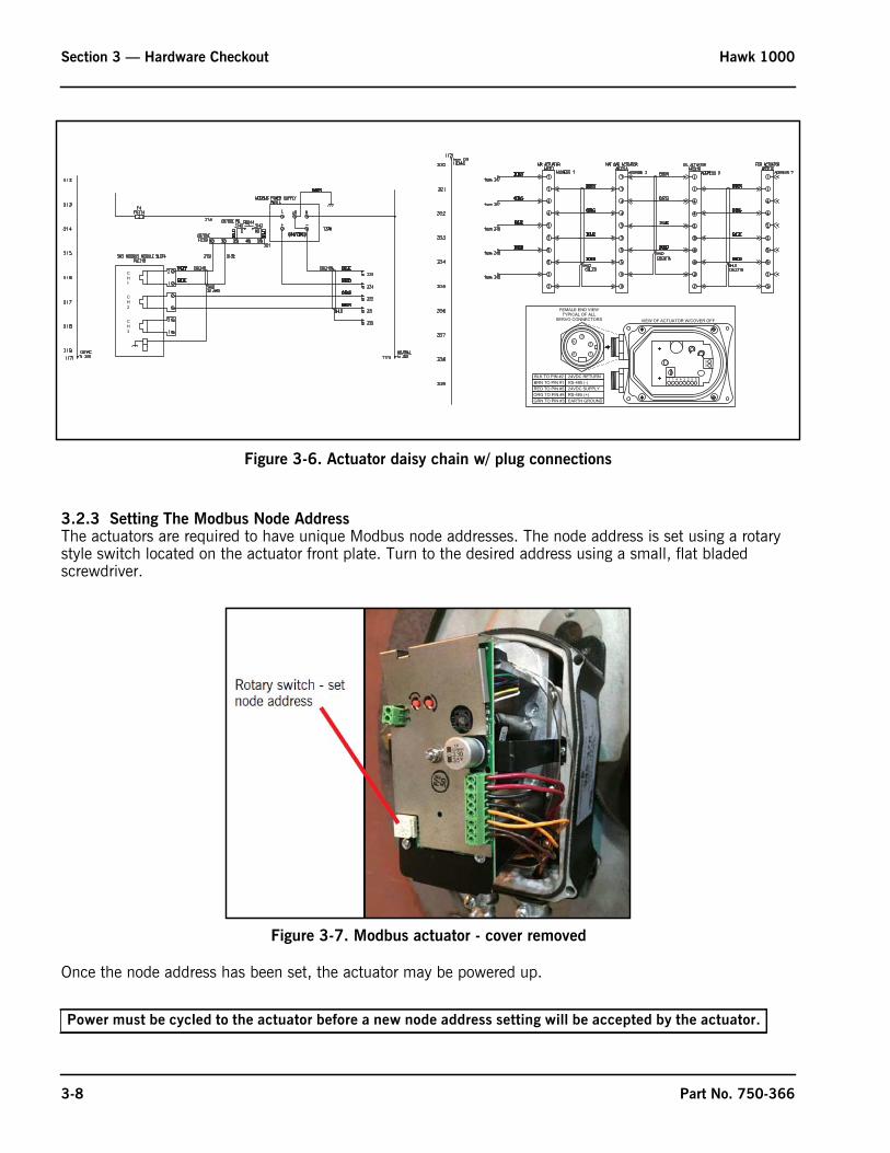
Figure 3-6. Actuator daisy chain w/ plug connections
3.2.3 Setting The Modbus Node AddressThe actuators are required to have unique Modbus node addresses. The node address is set using a rotary style switch located on the actuator front plate. Turn to the desired address using a small, flat bladed screwdriver.
Once the node address has been set, the actuator may be powered up.
Power must be cycled to the actuator before a new node address setting will be accepted by the actuator.
CH1
CH2
CH3
VIEW OF ACTUATOR W/COVER OFF
FEMALE END VIEWTYPICAL OF ALL
SERVO CONNECTORS
BLK TO PIN #2 24VDC RETURNBRN TO PIN #1 RS-485 (-)RED TO PIN #5 24VDC SUPPLYORG TO PIN #4 RS-485 (+)GRN TO PIN #3 EARTH GROUND
Figure 3-7. Modbus actuator - cover removed
3-8 Part No. 750-366

Hawk 1000 Section 3 — Hardware Checkout
Actuator Node Address Table:
3.2.4 Power/ Communications LEDEach actuator has a green Power/ Communications LED. The LED can assume one of three states:
OFF - check that 24 VDC power is present. The LED is also OFF when pressing either the CCW or CW red pushbutton.
ON Solid - power present but no commands received from PLC. ON Solid is the normal state for an actuator not required by the PLC at the time - such as the Fuel 2 Actuator when the Fuel Selector is in the Fuel 1 position.
Rapid Flickering - actuator is responding to PLC commands and sending position data.
3.2.5 Moving The ActuatorThe actuator can be moved clockwise or counterclockwise by pressing either one of two red buttons located on the actuator (Figure 3-8). One red button moves the actuator shaft clockwise, and the other moves the actuator shaft counter-clockwise. The servo will automatically stop when it reaches the end of its travel.
Moving of actuators manually should only be done when the main fuel valve is closed. Moving the actuators manually while the main fuel valve is open will generate a fault.
Releasing the manual pushbutton will allow the PLC to automatically command the actuators to position; therefore the buttons should not be used during commissioning, but only as a troubleshooting tool.
Actuator AddressAir Actuator 1Fuel 1 Actuator 22nd Fuel 1 Actuator 3Fuel 2 Actuator 52nd Fuel 2 Actuator 6FGR Actuator 7
There are open/ close pushbuttons on the actuator calibration screen on the HMI. These pushbuttons should be used when calibrating the actuators.
Clockwise or counter-clockwise actuator shaft rotation is deduced from the viewing perspective shown in Figure 3-8.
Part No. 750-366 3-9

Section 3 — Hardware Checkout Hawk 1000
Figure 3-8. Actuator manual pushbuttons
3-10 Part No. 750-366
www.cleaverbrooks.com
Section 4System Configuration
Introduction . . . . . . . . . . . . . . . . . . . . . . . . . . . . . . . . . . . . . . . . . . .4-2Logging In . . . . . . . . . . . . . . . . . . . . . . . . . . . . . . . . . . . . . . .4-2
Main Menu . . . . . . . . . . . . . . . . . . . . . . . . . . . . . . . . . . . . . . . . . . . .4-3Boiler Overview . . . . . . . . . . . . . . . . . . . . . . . . . . . . . . . . . . . . . . . . .4-4System Configuration . . . . . . . . . . . . . . . . . . . . . . . . . . . . . . . . . . . . .4-5
Logging In . . . . . . . . . . . . . . . . . . . . . . . . . . . . . . . . . . . . . . .4-6Fuel Configuration . . . . . . . . . . . . . . . . . . . . . . . . . . . . . . . . .4-11Flame Safeguard . . . . . . . . . . . . . . . . . . . . . . . . . . . . . . . . . .4-12Analog Inputs . . . . . . . . . . . . . . . . . . . . . . . . . . . . . . . . . . . .4-13CB Master Lead Lag . . . . . . . . . . . . . . . . . . . . . . . . . . . . . . .4-14CB 2 Boiler Lead Lag . . . . . . . . . . . . . . . . . . . . . . . . . . . . . .4-14Remote Modulation/Remote Set Point . . . . . . . . . . . . . . . . . . .4-16Actuator Selection . . . . . . . . . . . . . . . . . . . . . . . . . . . . . . . . .4-18Variable Frequency Drive . . . . . . . . . . . . . . . . . . . . . . . . . . . .4-19Options . . . . . . . . . . . . . . . . . . . . . . . . . . . . . . . . . . . . . . . .4-19Configuration Summary . . . . . . . . . . . . . . . . . . . . . . . . . . . . .4-24
Email Setup . . . . . . . . . . . . . . . . . . . . . . . . . . . . . . . . . . . . . . . . . .4-25SMTP Configuration . . . . . . . . . . . . . . . . . . . . . . . . . . . . . . .4-25Text/Email Contact List . . . . . . . . . . . . . . . . . . . . . . . . . . . . .4-25
PanelView Plus Setup . . . . . . . . . . . . . . . . . . . . . . . . . . . . . . . . . . . .4-26Change the Date and Time . . . . . . . . . . . . . . . . . . . . . . . . . . .4-26Installing a PV+ Program . . . . . . . . . . . . . . . . . . . . . . . . . . .4-28
Remote Monitoring . . . . . . . . . . . . . . . . . . . . . . . . . . . . . . . . . . . . .4-34

Section 4 — System Configuration Hawk 1000
4.1 IntroductionThe Hawk 1000 is equipped with a 6" color touch screen Human Machine Interface (HMI). The HMI along with the Burner Control display are the points of interface for the operator to monitor and control the boiler, and for the technician to configure and set up the system.
This section describes the HMI screens and their functions.
For information on the Burner Control (Flame Safeguard), refer to one of the following CB publications:
CB120E Burner Control 750-264
CB780E Burner Control 750-234
4.1.1 Logging InCertain actions on the HMI require a password before allowing user input. The Hawk 1000 employs two levels of security: Operator, and Service. When a password is required, the login entry window is displayed.
Pressing <User Name> or <Password> will bring up an alphanumeric keypad. Use this to enter your user name and password. A USB keyboard may also be used.
Figure 4-1. Firing Rate Screen
Figure 4-2. Login Keypad
4-2 Part No. 750-366

Hawk 1000 Section 4 — System Configuration
4.2 Main MenuThe Main Menu (Figure 4-3) is the first screen to appear when power is applied to the system. A header section at the top of the screen shows the current date and time, the user login status, a logout button and an alarm bell if an alarm is present. The rest of the screen consists of screen navigation buttons.
When the system is powered on for the first time, the <System Config>* button will indicate “System Config Required”. The screen will indicate “Commissioning Not Done” until initial configuration and commissioning have been completed. Note also that some screen buttons will not yet be available.
*In this manual, screen buttons on the HMI are identified by the button description with arrows on either side (e. g. <Main>).
Figure 4-3. Main Menu
Figure 4-4. Main Menu (system configuration required)
Part No. 750-366 4-3

Section 4 — System Configuration Hawk 1000
4.3 Boiler OverviewThe Boiler Overview display (Figure 4-5) serves as the main point of interface for the operator. The primary purpose of the display is to monitor the current status of the boiler.
Figure 4-5. Boiler Overview Screen
FIRETUBE
FLEXTUBE
MODEL 4/5
HOT WATER BOILERSSTEAM BOILERS
4-4 Part No. 750-366

Hawk 1000 Section 4 — System Configuration
4.4 System ConfigurationThe first step in commissioning t h e b o i l e r is to configure the control system options. The following items are configurable when in system configuration:
Note that if a configuration setting is marked with an asterisk and the setting is changed the Combustion Curves will be erased.
2 Configuration Summary screens are available. Configured values will be shown for all parameters.
If the <Confirm Options (Required)> pushbutton is visible, it must be pressed to accept the new system configuration.
Note: The boiler will not start while you are in a System Configuration screen.
! Caution
If System Configuration is entered with the boiler running, a safety shutdown will occur. Repeated shutdowns or nuisance shutdowns can cause premature equipment failure.
! Caution
The following screens should only be accessed by qualified personnel. Selections should never be made while the boiler is in operation.
• Boiler Media Steam or Hot Water• Boiler Type - Firetube, Flextube or M4/M5 boiler• Safety Valve Setpoint• NOx Level (PPM)• Number of Fuels• Fuel 1 Fuel Type• Fuel 1 Control Type (Parallel or Single Point)• Fuel 1 Turndown• Fuel 2 Fuel Type• Fuel 2 Control Type (Parallel, Single Point, or
Low High)• Fuel 2 Turndown• Flame Safeguard Selection• Revert to Pilot (CB120E Only)• Revert to Pilot Signal Select (CB120E Only)• Analog Input I:2.2• Remote Modulation/Setpoint Signal Selection• Actuator Selection• VFD Option Selection (requires additional
analog input module Slot 7)• VFD Bypass Option Selection
• O2 Analyzer (when this option is selected, type of analyzer must be specified - requires additional analog input module Slot 7)
• O2 Trim• Low O2 Shutdown Option• Hot Standby Option Selection• Combustion Air Temp Option Selection (requires
additional analog input module Slot 7)• Level Master Option selection (Steam Boiler)• Return Water Temperature (hot water only)• Outdoor Temp Reset Selection (hot water only)• Selectable overview screen graphic - Firetube,
Flextube, or M4/M5 boiler• 2 Boiler Lead Lag / Master Panel Lead Lag select• Remote Modulation Source select (Analog Input
/ Communications)• Remote Setpoint source select (Analog Input /
Communications)• Dual Set Point• Enter customer name, boiler ID and serial
number, Alarm Input #1-3 name if enabled.
Part No. 750-366 4-5

Section 4 — System Configuration Hawk 1000
Note: The firing rate will be put into manual mode upon entering System Configuration.
4.4.1 Logging InA login is required in order to access System Configuration. Pressing <System Config Required> from the Main screen will display the following:
Any time a gray button appears, a user I.D. and password are required for user input.
Pressing <System Config> will bring up the following screen:
Pressing <User Name> or <Password> will bring up an alphanumeric keypad. Use this (or the HMI hardware keypad) to enter your user name and password. A USB keyboard may also be used.
Type the password (user name) followed by the Enter key.
Figure 4-6. Enter System Configutration
Figure 4-7. Login Screen
4-6 Part No. 750-366

Hawk 1000 Section 4 — System Configuration
When a valid user name and password have been entered, the following screen will appear:
Figure 4-9. System Configuration (user logged in)
Pressing <System Config Required> displays a final warning:
Figure 4-8. Keypad
Part No. 750-366 4-7

Section 4 — System Configuration Hawk 1000
Press <Next> to begin the configuration process. The first step is selection of Boiler Media and Boiler Type.
In this example, “Firetube” is selected as the boiler type. After selecting the boiler media (steam or hot water) additional screen buttons will become available. Selecting “Steam” will bring up buttons for steam transmitter span, safety valve setpoint, and NOx level. To change the default values, press the desired button and a keypad will appear allowing user input.
Selecting boiler type and media will also bring up the <Next> button, allowing the user to advance to the next configuration screen.
The user must be logged in at the appropriate password level to change configuration data. If the user tries to change configuration data without having proper access rights, a pop-up window will appear and a password will be requested.
Figure 4-10. System Config Warning
Figure 4-11. Select Boiler Media & Type
4-8 Part No. 750-366

Hawk 1000 Section 4 — System Configuration
Figure 4-12. Boiler Media selected
If a valid user name and password are entered, the operator will be allowed to change data. The current user login status can be seen in the top right corner of each screen.
The color of the pushbutton will also indicate if the user has proper access rights.
Pressing the button of the value that needs modifying will pop-up a numeric keypad, allowing the operator to enter the new value. Notice that there is a range of valid entries at the top of the numeric keypad. An out-of-range entry will show up in red and require re-entering an acceptable value.
Enter the desired value and press the Enter key. If the entry is valid, the value will be accepted and the keypad will disappear.
Figure 4-13. Onscreen Keypad
Boiler MediaSelect Steam or Hot Water depending on the type of system.
KEYPAD INVALID ENTRY
Part No. 750-366 4-9

Section 4 — System Configuration Hawk 1000
Boiler TypeThe Boiler Type will display the proper Boiler graphic on the Boiler overview screen. The three choices for Boiler Type are: Firetube, Flextube and M4/M5
Boiler Type is also used to set limits on the maximum entry allowed for Safety Valve Setpoint (steam) or Max Rated Temperature (hot water).
Maximum Rated Temperature (Hot Water)
All Types = Between 200-400 Deg F
Safety Valve Setpoint (steam)
On a steam boiler, the proper safety valve setting should correspond to the pressure setting of the steam safety valve(s) on the boiler.
A hot water boiler is configured similarly. The max rated temperature of the boiler should be entered. This number should not exceed the maximum design temperature of the boiler. Default for hot water boilers is 250º F. Contact your local Cleaver-Brooks representative if you do not know the maximum temperature rating of your boiler.
Steam Transmitter Span The span setting for the steam transmitter is adjustable. The Steam Transmitter Span value cannot be set lower than the Safety Valve Setpoint and cannot be set higher than 1000. Initially the Steam Transmitter Span is populated with a default value:
In hot water systems the supply temperature transmitter is not scalable. The transmitters used must be rated to accommodate the required range:
If the Max Rated Temperature O 250 Deg F the Supply Temp Transmitter is set to 50-300 Deg F.
If the Max Rated Temperature > 250 Deg F the Supply Temp Transmitter is set to 50-500 Deg F.
Safety Valve Setpoint MaxFiretube 400 psiFlextube 250 psiM4/M5 675 psi
! Warning
The safety valve setting is critical to the proper operation of the boiler. An incorrect setting could lead to unsafe operation.
Safety Valve Setpoint Steam Transmitter Span15.0 psi or less 15.015.1 to 150.0 150.0150.1 to 300.0 300.0300.1 to 500.0 500.0500.1 to 600.0 600.0600.1 or greater Safety Valve Setpoint
4-10 Part No. 750-366

Hawk 1000 Section 4 — System Configuration
NOx Level (PPM)
Enter the NOx Level for this specific job.
NOx Level can range from 5-150 PPM and is initialized with a value of 60.0 PPM.
Note: On Steam Boilers If NOx Level is less than 60.0 PPM Remote Setpoint and Dual Setpoint Options are Not Available.
When all configurable items on this screen have valid entries, the <Next> button will appear, allowing System Configuration to continue. The next screen is fuel configuration, where number and type of fuels, turndown, and combustion control method are selected.
4.4.2 Fuel Configuration
Figure 4-14. Fuel configuration
Number of Fuels
Enter the Number of Fuels for this application.
Acceptable values are either 1 or 2. High/Low control method MUST be fuel 2.
If the system has only one fuel and that fuel is Oil, the number of fuels must be selected as 2 and Oil must be Fuel 2. Fuel 1 Actuator does not require commissioning.
Fuel 1/Fuel 2 Type
Select the Fuel type for each fuel for this specific job
When pressing the Fuel Type push button a selector is displayed
The up/down arrows can be used to select the correct fuel. Press the enter key to accept the selection.
Fuel 1/Fuel 2 Turndown
Enter the Turndown for each fuel for this specific application.
The turndown entry affects the boiler efficiency calculations - it has no impact on the burner's actual turndown. Turndown ratio is established during burner commissioning by a qualified burner technician.
Part No. 750-366 4-11

Section 4 — System Configuration Hawk 1000
Fuel 1/Fuel 2 Control Method
Select the type of control method for each fuel for this specific job.
Acceptable values for fuel 1 are Parallel Positioning or Single Point positioning.
Acceptable values for fuel 2 are Parallel Positioning, Single Point positioning or Low/High.
Note - Single Point positioning cannot be selected in conjunction with parallel positioning.
When fuel configuration is complete, press <Next> to go to Flame Safeguard configuration.
4.4.3 Flame Safeguard
Figure 4-15. FSG screen
Flame Safeguard
Select the type of Flame Safeguard used for the specific job.
The CB780E and CB120E are the two selections available on the Hawk 1000
If CB120E is selected the Revert to Pilot Option is available (not available on the CB780E).
Revert to Pilot
The Revert to Pilot selection is made by pressing the <Revert to Pilot> push button until “Yes” is displayed on the pushbutton.
If Revert to Pilot is selected there are two ways to initiate the Revert to Pilot sequence - either by Process Variable (Steam Pressure/Supply Temperature) or by Digital Input.
If Process Variable is selected the setpoint for Revert to Pilot must be entered from the Setpoint Screen - see Section 5 E - Setpoints for more details.
If Digital Input is selected, when discrete input I:5.7 ALFCO is turned off, Revert to Pilot will be initiated (as long as the boiler is not currently in hot standby or warmup mode).
4-12 Part No. 750-366
Hawk 1000 Section 4 — System Configuration
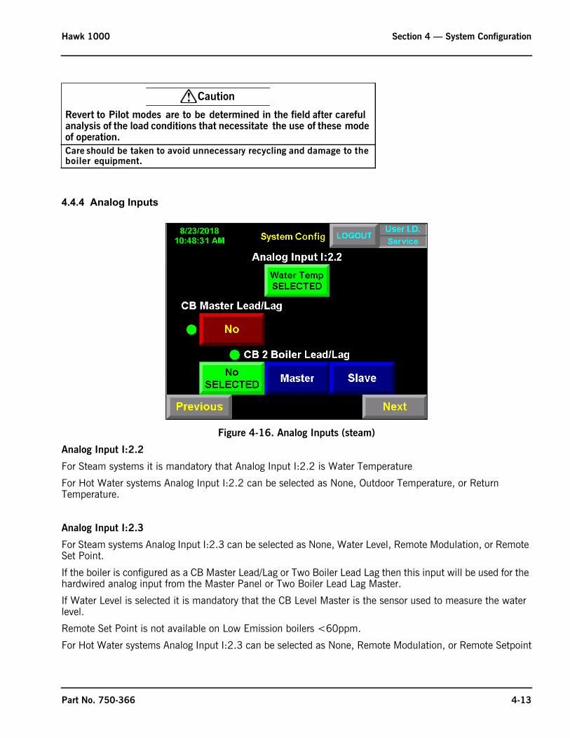
4.4.4 Analog Inputs
Figure 4-16. Analog Inputs (steam)
Analog Input I:2.2
For Steam systems it is mandatory that Analog Input I:2.2 is Water Temperature
For Hot Water systems Analog Input I:2.2 can be selected as None, Outdoor Temperature, or Return Temperature.
Analog Input I:2.3
For Steam systems Analog Input I:2.3 can be selected as None, Water Level, Remote Modulation, or Remote Set Point.
If the boiler is configured as a CB Master Lead/Lag or Two Boiler Lead Lag then this input will be used for the hardwired analog input from the Master Panel or Two Boiler Lead Lag Master.
If Water Level is selected it is mandatory that the CB Level Master is the sensor used to measure the water level.
Remote Set Point is not available on Low Emission boilers <60ppm.
For Hot Water systems Analog Input I:2.3 can be selected as None, Remote Modulation, or Remote Setpoint
! Caution
Revert to Pilot modes are to be determined in the field after careful analysis of the load conditions that necessitate the use of these mode of operation.Care should be taken to avoid unnecessary recycling and damage to the boiler equipment.
Part No. 750-366 4-13

Section 4 — System Configuration Hawk 1000
If Analog Input I:2.3 is used for Remote Modulation or Remote Set Point then neither Remote Modulation by communications or Remote Setpoint by communications are available.
4.4.5 CB Master Lead LagIf the boiler will be utilized in a CB Master Panel control system, select <CB Master Lead Lag>. The boiler controller will need the proper wiring connections with the master controller to function properly. See the CB Master Panel manual (#750-375) for further information on Master Lead/Lag configuration and operation.
The figure below shows the different system configuration options available.
Figure 4-17. CB Master Lead Lag
Note that with CB Master Lead Lag enabled, certain boiler configuration selections will be automatically determined and their buttons deactivated (signified by a gray button).
4.4.6 CB 2 Boiler Lead LagFor 2 Boiler Lead Lag select Master or Slave. If the boiler controller being configured has the header transmitter connected to it, this boiler will be the “Master” - if not, it will be the “Slave” (“Master” as used here should not be confused with the CB Master Lead Lag option above).
If Master is selected, the 2 Boiler Lead Lag Setup and Control screens will now be available from the Main Menu.
CB 2 Boiler Lead Lag is available Hardwired or by Communications beginning with PLC program revision 98500509_001_011 (or 98500509_001_012 metric).
Note that with CB 2 Boiler Lead Lag enabled, certain boiler configuration selections will be automatically determined and their buttons deactivated (signified by a gray button).
MASTER SELECTED [WATER LEVEL, REM MOD,
[DUAL SETPOINT DISALLOWED] [HOT STANDBY SELECTED]
REM SP DISALLOWED]
4-14 Part No. 750-366
Hawk 1000 Section 4 — System Configuration
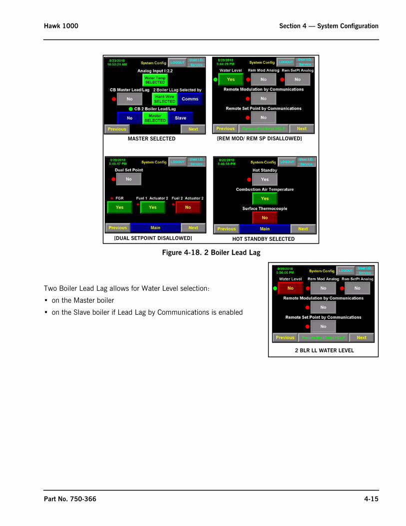
Figure 4-18. 2 Boiler Lead Lag
Two Boiler Lead Lag allows for Water Level selection:
• on the Master boiler
• on the Slave boiler if Lead Lag by Communications is enabled
MASTER SELECTED [REM MOD/ REM SP DISALLOWED]
[DUAL SETPOINT DISALLOWED] HOT STANDBY SELECTED
2 BLR LL WATER LEVEL
Part No. 750-366 4-15

Section 4 — System Configuration Hawk 1000
4.4.7 Remote Modulation/Remote Set PointSignals for Remote Modulation or Remote Setpoint can be provided by either an analog input signal or written directly into the PLC by communications (Ethernet).
Remote Modulation by Analog Input
This configures the Boiler Controller to receive a remote 4-20mA signal on input I:2.3 to control the firing rate of the boiler.
The signal is scaled from 0-100%, (4ma = Low Fire and 20ma = High Fire).
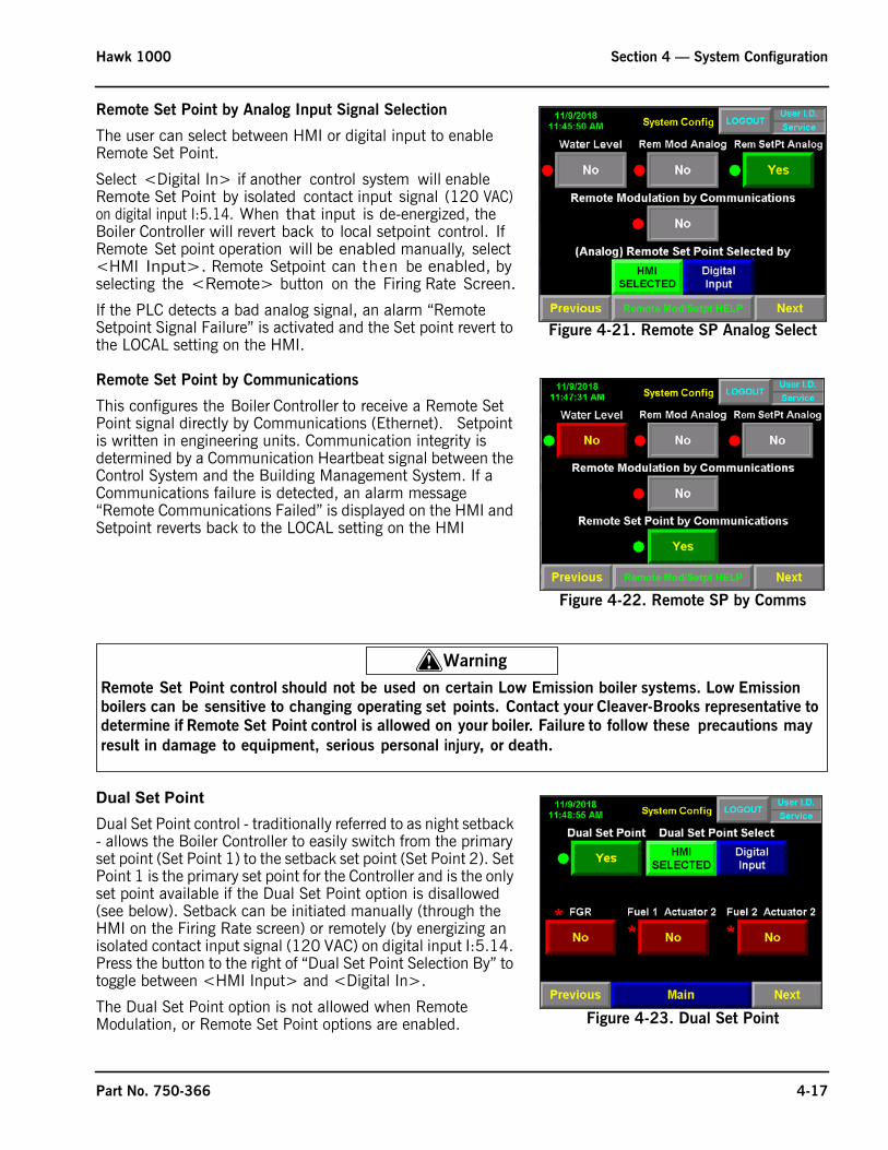
Remote Modulation by Analog Input Signal Selection
The user can select between HMI or digital input to enable Remote Modulation.
Select <Digital In> if another control system will enable Remote Modulation by isolated contact input signal (120 VAC) on digital input I:5.14. When that input is de-energized, the Boiler Controller will revert back to local firing rate control. If Remote Modulation operation will be enabled manually, select <HMI Input>. Remote Modulation can then be enabled, by selecting the <Remote> button on the Firing Rate Screen.
If the PLC detects a bad analog signal, an alarm “Remote Modulation Signal Failure” is activated and the Firing Rate revert to the LOCAL setting on the HMI.
Remote Modulation by Communications
This configures the Boiler Controller to receive a Remote Modulation signal directly by Communications (Ethernet). Modulation units range from 0-100%. Communication integrity is determined by a Communication Heartbeat signal between the Control System and the Building Management System. If a Communications failure is detected, an alarm message “Remote Communications Failed” is displayed on the HMI and Modulation reverts back to the LOCAL setting on the HMI
Remote Set Point by Analog Input
This configures the Boiler Controller to receive a remote 4-20mA signal on input I:2.3 to vary the set point of the boiler.
Note: Remote Setpoint is not allowed for low emission s team boilers.
With Remote Setpoint selected, the analog signal can be scaled to the engineering units on the “Alarm and Limits” Screen, by setting the Remote Setpoint Scaling values (zero and span) of the remote 4-20mA signal
Figure 4-19. Remote Modulation signal select
Figure 4-20. Remote Mod/Setpoint by Communications
4-16 Part No. 750-366
Hawk 1000 Section 4 — System Configuration
Remote Set Point by Analog Input Signal Selection
The user can select between HMI or digital input to enable Remote Set Point.
Select <Digital In> if another control system will enable Remote Set Point by isolated contact input signal (120 VAC) on digital input I:5.14. When that input is de-energized, the Boiler Controller will revert back to local setpoint control. If Remote Set point operation will be enabled manually, select <HMI Input>. Remote Setpoint can then be enabled, by selecting the <Remote> button on the Firing Rate Screen.
If the PLC detects a bad analog signal, an alarm “Remote Setpoint Signal Failure” is activated and the Set point revert to the LOCAL setting on the HMI.
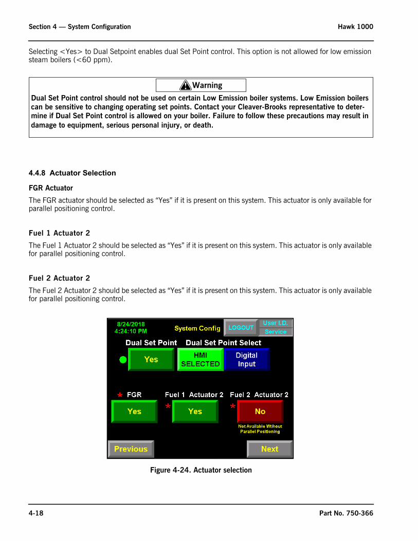
Remote Set Point by Communications
This configures the Boiler Controller to receive a Remote Set Point signal directly by Communications (Ethernet). Setpoint is written in engineering units. Communication integrity is determined by a Communication Heartbeat signal between the Control System and the Building Management System. If a Communications failure is detected, an alarm message “Remote Communications Failed” is displayed on the HMI and Setpoint reverts back to the LOCAL setting on the HMI
Dual Set PointDual Set Point control - traditionally referred to as night setback - allows the Boiler Controller to easily switch from the primary set point (Set Point 1) to the setback set point (Set Point 2). Set Point 1 is the primary set point for the Controller and is the only set point available if the Dual Set Point option is disallowed (see below). Setback can be initiated manually (through the HMI on the Firing Rate screen) or remotely (by energizing an isolated contact input signal (120 VAC) on digital input I:5.14. Press the button to the right of “Dual Set Point Selection By” to toggle between <HMI Input> and <Digital In>.
The Dual Set Point option is not allowed when Remote Modulation, or Remote Set Point options are enabled.
Figure 4-21. Remote SP Analog Select
Figure 4-22. Remote SP by Comms
! Warning
Remote Set Point control should not be used on certain Low Emission boiler systems. Low Emission boilers can be sensitive to changing operating set points. Contact your Cleaver-Brooks representative to determine if Remote Set Point control is allowed on your boiler. Failure to follow these precautions may result in damage to equipment, serious personal injury, or death.
Figure 4-23. Dual Set Point
Part No. 750-366 4-17
Section 4 — System Configuration Hawk 1000
Selecting <Yes> to Dual Setpoint enables dual Set Point control. This option is not allowed for low emission steam boilers (<60 ppm).
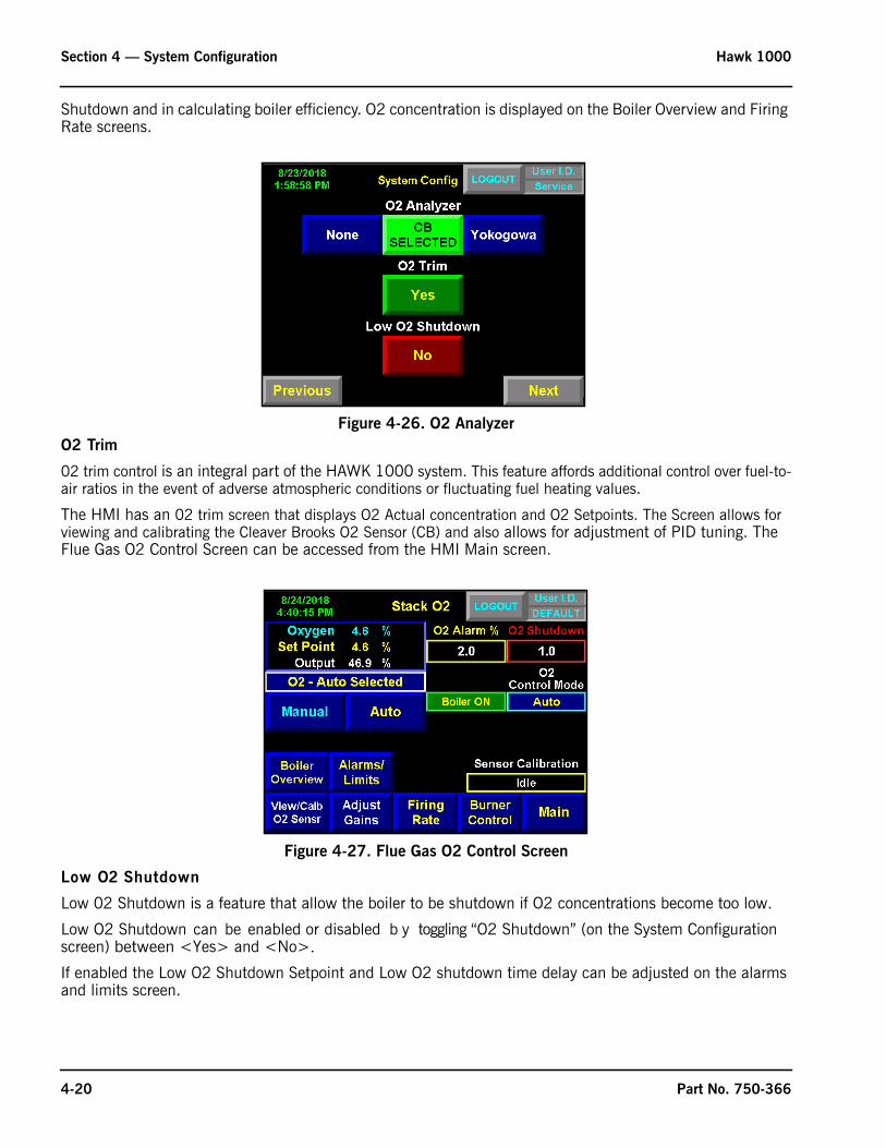
4.4.8 Actuator Selection
FGR Actuator
The FGR actuator should be selected as “Yes” if it is present on this system. This actuator is only available for parallel positioning control.
Fuel 1 Actuator 2
The Fuel 1 Actuator 2 should be selected as “Yes” if it is present on this system. This actuator is only available for parallel positioning control.
Fuel 2 Actuator 2
The Fuel 2 Actuator 2 should be selected as “Yes” if it is present on this system. This actuator is only available for parallel positioning control.
Figure 4-24. Actuator selection
! Warning
Dual Set Point control should not be used on certain Low Emission boiler systems. Low Emission boilers can be sensitive to changing operating set points. Contact your Cleaver-Brooks representative to deter-mine if Dual Set Point control is allowed on your boiler. Failure to follow these precautions may result in damage to equipment, serious personal injury, or death.
4-18 Part No. 750-366

Hawk 1000 Section 4 — System Configuration
4.4.9 Variable Frequency Drive
VFD Type
Select the appropriate VFD Type for this specific job.
The available options are None, PowerFlex, and Other Mfg.
Selecting <PowerFlex> assumes you are using either the PowerFlex 400, PowerFlex 70 Enhanced, or PowerFlex 700 Vector drive.
All drives types use 4-20mA command and feedback.
VFD Bypass
VFD Bypass should be selected “Yes” if VFD Bypass is on this specific job.
An Air/Fuel curve must be configured for each fuel while in bypass mode.
VFD bypass allows the boiler system the ability to keep the combustion blower motor running even if the Variable Frequency Drive is taken out of the loop for any reason.
Figure 4-25. VFD screen
Variable Frequency Drive for Combustion Air Fan Motor
Variable frequency drives (VFDs) offer many benefits to reduce energy costs and extend the life of mechanical equipment.
The optional Variable Frequency Drive (VFD; see Figure 2-7) controls the speed of the combustion air fan motor for the purposes of improving boiler efficiency and reducing electrical energy consumption.
4.4.10 Options
Oxygen Analyzer
The Oxygen (O2) Analyzer (See Figure 2-8) is available for monitoring stack flue gas oxygen concentration. The O2 Analyzer transmits an analog signal to the controller. The O2 signal is used for Low O2 alarms, Low O2
Part No. 750-366 4-19
Section 4 — System Configuration Hawk 1000
Shutdown and in calculating boiler efficiency. O2 concentration is displayed on the Boiler Overview and Firing Rate screens.
O2 Trim
02 trim control is an integral part of the HAWK 1000 system. This feature affords additional control over fuel-to-air ratios in the event of adverse atmospheric conditions or fluctuating fuel heating values.
The HMI has an 02 trim screen that displays O2 Actual concentration and O2 Setpoints. The Screen allows for viewing and calibrating the Cleaver Brooks O2 Sensor (CB) and also allows for adjustment of PID tuning. The Flue Gas O2 Control Screen can be accessed from the HMI Main screen.
Low O2 Shutdown
Low 02 Shutdown is a feature that allow the boiler to be shutdown if O2 concentrations become too low.
Low O2 Shutdown can be enabled or disabled b y toggling “O2 Shutdown” (on the System Configuration screen) between <Yes> and <No>.If enabled the Low O2 Shutdown Setpoint and Low O2 shutdown time delay can be adjusted on the alarms and limits screen.
Figure 4-26. O2 Analyzer
Figure 4-27. Flue Gas O2 Control Screen
4-20 Part No. 750-366

Hawk 1000 Section 4 — System Configuration
Hot Standby
The Hot Standby function maintains a minimum water temperature to keep the boiler in a state of readiness for a load demand. While operating, the boiler remains at the minimum firing rate and cycles on-and-off relative to the Hot Standby water temperature set point. This set point is configured on the Setpoints screen (accessed from the Main Screen).
Hot Standby can be enabled or disabled by Pressing the “Hot Standby” button to toggle between <Yes> and <No>. The boiler overview and firing rate screens will indicate when the boiler is in hot standby.
Hot Stand-By can be initiated manually by pressing <Force Hot Standby> on the Firing Rate screen. The boiler will remain in standby until the button is again pressed.
If two boiler Lead Lag or CB Master Panel Lead Lag is selected, Hot Standby is automatically enabled and cannot be changed by the user.
If two boiler Lead Lag or CB Master Panel Lead Lag is selected and the control is operating in Remote Mode, Force Hot Standby is automatically disabled and cannot be enabled by the user.
See Section 5 - Commissioning for more on Hot Standby.
Figure 4-29. Hot Standby
Figure 4-28. Low O2 Shutdown
Overview - Hot Standby Force Hot Standby
Part No. 750-366 4-21
Section 4 — System Configuration Hawk 1000
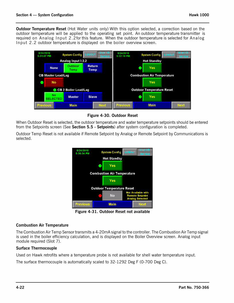
Outdoor Temperature Reset (Hot Water units only) With this option selected, a correction based on the outdoor temperature will be applied to the operating set point. An outdoor temperature transmitter is required on Analog Input 2.2for this feature. When the outdoor temperature is selected for Analog Input 2.2 outdoor temperature is displayed on the boiler overview screen.
Figure 4-30. Outdoor Reset
When Outdoor Reset is selected, the outdoor temperature and water temperature setpoints should be entered from the Setpoints screen (See Section 5.5 - Setpoints) after system configuration is completed.
Outdoor Temp Reset is not available if Remote Setpoint by Analog or Remote Setpoint by Communications is selected.
Combustion Air Temperature
The Combustion Air Temp Sensor transmits a 4-20mA signal to the controller. The Combustion Air Temp signal is used in the boiler efficiency calculation, and is displayed on the Boiler Overview screen. Analog input module required (Slot 7).
Surface Thermocouple
Used on Hawk retrofits where a temperature probe is not available for shell water temperature input.
The surface thermocouple is automatically scaled to 32-1292 Deg F (0-700 Deg C).
Figure 4-31. Outdoor Reset not available
4-22 Part No. 750-366

Hawk 1000 Section 4 — System Configuration
Boiler Information
The customer name, boiler ID, and boiler serial number and can be entered. This information is displayed on the System Information Screen. To enter this information, press the text display button beneath the description. An alphanumeric keypad pop-up window appears.
Figure 4-33. Boiler information
Once all the information is entered, press the carriage return button. The Boiler ID and Serial Number are each limited to 20 characters, including spaces.
Auxiliary Alarm 1-3
If the system has auxiliary alarms the text that is displayed when the alarm is triggered can be entered. To enter this information, press the text display button beneath the description. An alphanumeric keypad pop-up window appears.
Once all the information is entered, press the carriage return button. The auxiliary alarms are each limited to 20 characters, including spaces.
Auxiliary alarm 1 must be wired to Slot 1 Input 13
Figure 4-32. Combustion Air Temp, Surface Thermocouple select
Part No. 750-366 4-23

Section 4 — System Configuration Hawk 1000
Auxiliary alarm 2 must be wired to Slot 1 Input 14
Auxiliary alarm 3 must be wired to Slot 1 Input 15
For example: If Auxiliary Alarm 1 is entered as Low Water Flow and Discrete Input I:1.13 is “On” the alarm displayed on the HMI for Auxiliary Alarm 1 will read “Aux 1 - Low Water Flow”.
Figure 4-34. Aux inputs
4.4.11 Configuration SummaryOnce the System Configuration settings have been entered the entries can be viewed from the System Configuration Summary screens.
Note: The “Confirm Options” push button is only visible if this is a new system configuration or a system configuration parameter marked with an asterisk has been changed.
Figure 4-35. Configuration summary
To complete system configuration, press the <Confirm Options> pushbutton on the Options Summary Screen.
The Configuration selections may be changed after the HAWK 1000 is installed. However, for many of the options, additional hardware is required to make the function work. Please refer to the parts section for the required hardware.
After confirming the current configuration, press <Main> to return to the Main screen.
Page 1 Page 2
4-24 Part No. 750-366

Hawk 1000 Section 4 — System Configuration
4.5 Email SetupEmail or text messages can be send directly from the PanelView Plus, provided SMTP Server Configuration has been completed.
The PV+ 7 must be at firmware revision 9.0 or greater.
4.5.1 SMTP Configuration
SMTP (Simple Mail Transfer Protocol) is a standard protocol for the exchange of electronic mail over the Internet. It will be the user’s responsibility to determine the SMTP server information for email configuration; an example configuration is shown below. A help screen is available (press <SMTP Help>). User’s IT personnel should be consulted if necessary.
4.5.2 Text/Email Contact ListThe HMI will store up to six email addresses. Each can be receive enabled (WILL SEND) or disabled (WILL NOT SEND). Enabled addresses will receive an email for every alarm activation.
Press <Email Help> for assistance in configuring this page, or consult the appropriate IT personnel.
Figure 4-36. Configuration Confirmed
Figure 4-37. SMTP Configuration (example)
Part No. 750-366 4-25

Section 4 — System Configuration Hawk 1000
4.6 PanelView Plus SetupThe PanelView Plus terminal has onboard software to perform and configure terminal operations. To access the internal PanelView settings (PanelView Configuration Mode) press <PV+ Config> on the Hawk Main Screen.
4.6.1 Change the Date and TimeSelect Terminal Settings>Time/Date/Regional Settings>Date. The current date appears in the Year, Month, and Day fields.
Press the Year, Month, and Day buttons to change the values. Press <OK> when done.
To change the time, Select Terminal Settings>Time/Date/Regional Settings>Time. values.Press the Hour, Minute, and Seconds buttons to change the values. Press <OK> when done.
To change the time zone, select Terminal Settings>Time/Date/Regional Settings>Time Zone.
Figure 4-38. Email List
Figure 4-39. Date Settings
4-26 Part No. 750-366

Hawk 1000 Section 4 — System Configuration
Press the Daylight Savings button to enable or disable daylight savings for the selected time zone. Daylight Savings is set to Yes for all time zones except for Japanese, which does not support daylight savings.
Daylight savings changes are not permanently applied until you close the Time Zone screen.
Press the <Use Daylight Savings> button to select Yes or No. Click OK when done, then <OK> again to return to Terminal Settings.
Figure 4-40.
Figure 4-41.
Part No. 750-366 4-27
Section 4 — System Configuration Hawk 1000
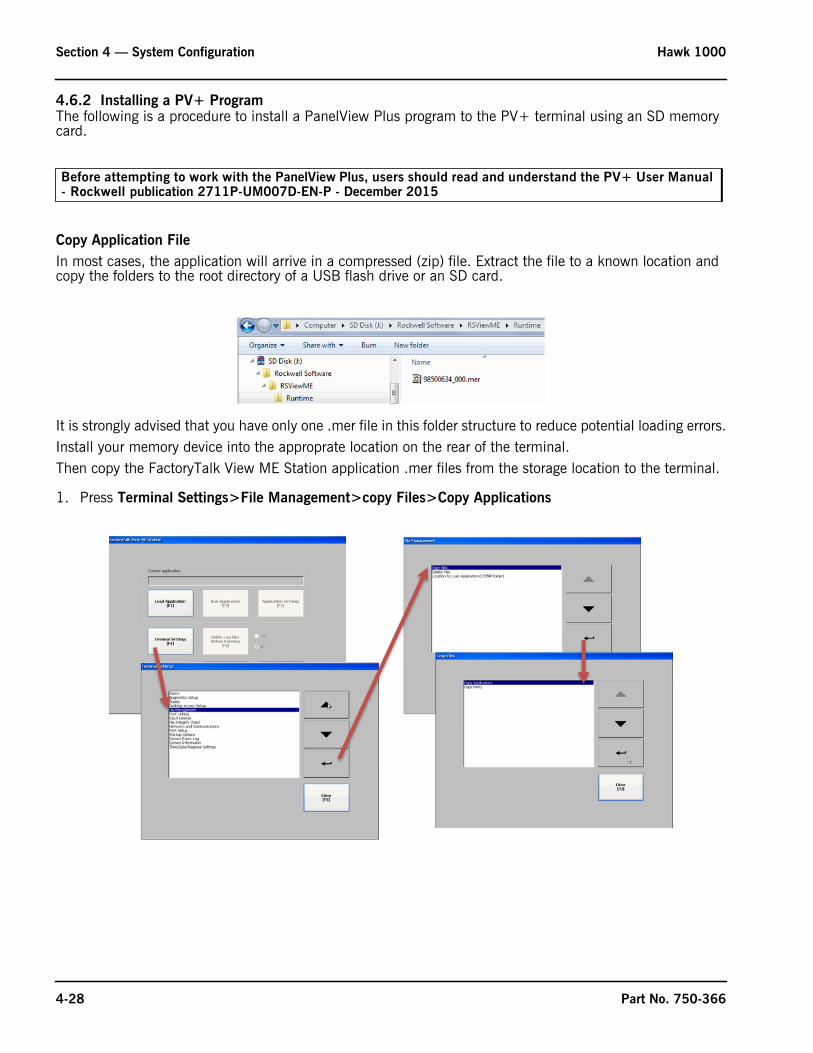
4.6.2 Installing a PV+ ProgramThe following is a procedure to install a PanelView Plus program to the PV+ terminal using an SD memory card.
Copy Application FileIn most cases, the application will arrive in a compressed (zip) file. Extract the file to a known location and copy the folders to the root directory of a USB flash drive or an SD card.
It is strongly advised that you have only one .mer file in this folder structure to reduce potential loading errors.Install your memory device into the approprate location on the rear of the terminal.Then copy the FactoryTalk View ME Station application .mer files from the storage location to the terminal.
1. Press Terminal Settings>File Management>copy Files>Copy Applications
Before attempting to work with the PanelView Plus, users should read and understand the PV+ User Manual - Rockwell publication 2711P-UM007D-EN-P - December 2015
4-28 Part No. 750-366

Hawk 1000 Section 4 — System Configuration
2. Press Source to select the location of the file you want to copy:
• External Storage 1 - SD card loaded in the card slot of the terminal
• External Storage 2 - USB flash drive connected to a USB host port
3. Select a file from the storage location.4. Press Destination on the same dialog box. 5. Press Destination to select the location to copy the file. The destination must be different than the source
location, and should be Internal Storage.
6. Press Copy to copy the selected file to the destination. If the file exists, you are asked if you want to overwrite the file.
7. Select Yes or No.8. Return to the FactoryTalk View Machine Edition Configuration Dialog box by pressing Close as required.
Part No. 750-366 4-29

Section 4 — System Configuration Hawk 1000
Load ApplicationIt is recommended that prior to loading an application that the terminal Ethernet is connected to only the PLC Ethernet. Do not connect to the plant network until the configuration is complete.To run a FactoryTalk View ME .mer application on the terminal, you must first load the application. You can load the application from internal storage or nonvolatile memory in the terminal, an SD card, or a USB flash drive. However, it is recommended that you always copy and run the application from the internal storage.Follow these steps to load and run an application.1. Press Load Application from the FactoryTalk View ME Station dialog box.
2. Press Source to select the location of the file you want to load:
• Internal Storage - nonvolatile memory of the terminal (preferred).
• External Storage 1 - SD card loaded in the card slot of the terminal.
• External Storage 2 - USB flash drive connected to a USB host port.
3. Select the .mer file from the list by using the up and down cursor keys.
Note: There should only be one application loaded on the terminal to eliminate the possibility of loading the incorrect application. Refer to Delete Application section to remove unused applications.
4. Press Load to load the selected application.
4-30 Part No. 750-366

Hawk 1000 Section 4 — System Configuration
You are asked if you want to replace the terminal's communication configuration with the configuration in the application.
5. Select Yes or No.
Select Yes to use the communication settings in the application. Use this option if this is a new installation. The PLC processor communications path will use IP address 192.168.1.101.
Select No to use the communication settings of the terminal. Use this option if you are running the application on a previously configured system in which the PLC processor communications path was changed.
6. To run the application that you loaded, press Run Application on the FactoryTalk View ME Station dialog box.
TIP: Applications generate log files (trends, alarm history, etc). To delete log files before running an application, select Delete Log Files Before Running on the Configuration Mode dialog box. Deleting log files reclaims terminal memory. It is recommended to select No.
Part No. 750-366 4-31
Section 4 — System Configuration Hawk 1000
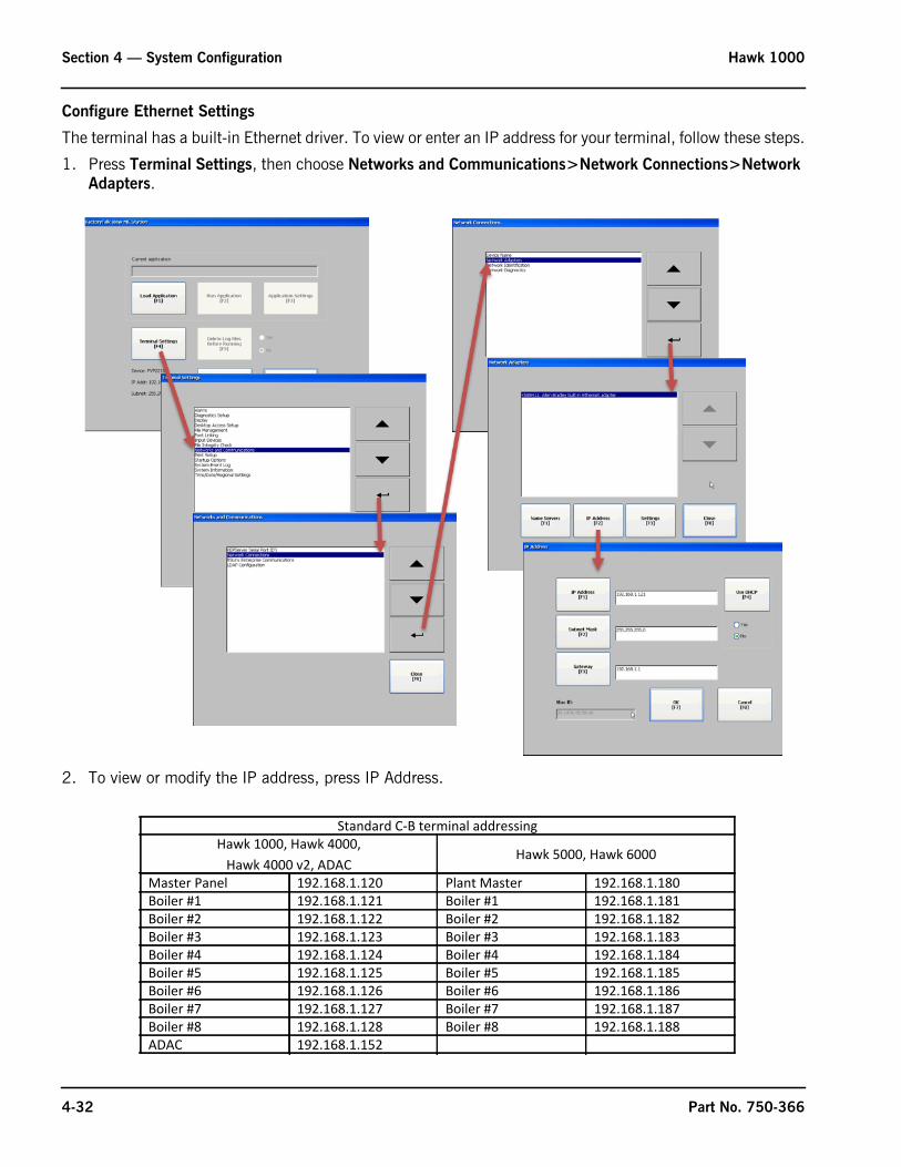
Configure Ethernet Settings
The terminal has a built-in Ethernet driver. To view or enter an IP address for your terminal, follow these steps.
1. Press Terminal Settings, then choose Networks and Communications>Network Connections>Network Adapters.
2. To view or modify the IP address, press IP Address.
Standard C-B terminal addressingHawk 1000, Hawk 4000,
Hawk 4000 v2, ADACHawk 5000, Hawk 6000
Master Panel 192.168.1.120 Plant Master 192.168.1.180Boiler #1 192.168.1.121 Boiler #1 192.168.1.181Boiler #2 192.168.1.122 Boiler #2 192.168.1.182Boiler #3 192.168.1.123 Boiler #3 192.168.1.183Boiler #4 192.168.1.124 Boiler #4 192.168.1.184Boiler #5 192.168.1.125 Boiler #5 192.168.1.185Boiler #6 192.168.1.126 Boiler #6 192.168.1.186Boiler #7 192.168.1.127 Boiler #7 192.168.1.187Boiler #8 192.168.1.128 Boiler #8 192.168.1.188ADAC 192.168.1.152
4-32 Part No. 750-366

Hawk 1000 Section 4 — System Configuration
3. To enable or disable DHCP assignment of addresses, press Use DHCP. Select No.If DHCP is enabled or set to Yes, IP addresses are automatically assigned to newly attached devices on the network. Cleaver-Brooks does not use this selection.
If DHCP is disabled or set to No, you can manually enter the IP address. Press IP Address, Subnet Mask, and Gateway to enter IP formatted addresses. For Cleaver-Brooks systems, you must select this option.
4. Press OK when done.
If prompted, reset the device from the FactoryTalk View ME Station dialog box.5. Press Close.
Change the communications path
The application is generally sent with the communications path set to the default PLC IP address. Should this need changing to satisfy customer's network requirements:
1. Press Terminal Settings>Networks and Communications>RSLinx Enterprise Communications.
2. Select the controller in the tree.
Note: The 1769-L32E and 1769-L35E processors will be seen differently than the 1769-L24ER, 1769-L30ER, and 1769-L33ER. Select the path accordingly.• For the 1769-L32E and 1769-L35E processors, if the PLC program number is not highlighted, use the arrow keys to
do so.
• For the 1769-L24ER, 1769-L30ER, and 1769-L33ER processors, if the controller is not highlighted, use the arrow keys to do so.
Part No. 750-366 4-33

Section 4 — System Configuration Hawk 1000
4.6.3 Viewing the PV+ FirmwareTo check the PV+ firmware version, from the Configuration Mode main screen, go to Terminal Settings> System Information> About FactoryTalk View ME Station.
4.7 Remote MonitoringThe PanelView Plus HMI provides Web Server functionality, allowing for easy access to plant floor HMI applications. There is no need to install any additional Rockwell software on the browser computer.
Once you have an Ethernet connection between a computer and the PanelView Plus terminal, simply choose a web browser such as Internet Explorer or Google Chrome and type in the IP address of the HMI running the application you wish to view. Note there can only be one connection to an HMI at a time.
Figure 4-43. Remote monitoring
Figure 4-42. View Firmware
4-34 Part No. 750-366
www.cleaverbrooks.com
Section 5Commissioning
Commissioning the Actuators . . . . . . . . . . . . . . . . . . . . . . . . . . . . . . . . . . . . . . . . . . . . . . . . 5-2Setting Combustion - Parallel Positioning . . . . . . . . . . . . . . . . . . . . . . . . . . . . . . . . . . . . . . . . 5-4
Store Purge . . . . . . . . . . . . . . . . . . . . . . . . . . . . . . . . . . . . . . . . . . . . . . . . . . . . 5-5Store Lightoff . . . . . . . . . . . . . . . . . . . . . . . . . . . . . . . . . . . . . . . . . . . . . . . . . . . 5-6Curve Setup . . . . . . . . . . . . . . . . . . . . . . . . . . . . . . . . . . . . . . . . . . . . . . . . . . . 5-6
Setting Combustion - Single Point Positioning . . . . . . . . . . . . . . . . . . . . . . . . . . . . . . . . . . . . . 5-7VFD or O2 Trim . . . . . . . . . . . . . . . . . . . . . . . . . . . . . . . . . . . . . . . . . . . . . . . . . 5-7No VFD or O2 Trim . . . . . . . . . . . . . . . . . . . . . . . . . . . . . . . . . . . . . . . . . . . . . . 5-7
Setting Combustion - Low/High/Low . . . . . . . . . . . . . . . . . . . . . . . . . . . . . . . . . . . . . . . . . . . 5-7Firing Rate Screen . . . . . . . . . . . . . . . . . . . . . . . . . . . . . . . . . . . . . . . . . . . . . . . . . . . . . . . . 5-8
Remote Setpoint/Remote Modulation . . . . . . . . . . . . . . . . . . . . . . . . . . . . . . . . . . 5-10Alarms and Limits . . . . . . . . . . . . . . . . . . . . . . . . . . . . . . . . . . . . . . . . . . . . . . . . . . . . . . . . 5-11
High Stack Temperature . . . . . . . . . . . . . . . . . . . . . . . . . . . . . . . . . . . . . . . . . . . 5-11Low O2 . . . . . . . . . . . . . . . . . . . . . . . . . . . . . . . . . . . . . . . . . . . . . . . . . . . . . . 5-11Low Steam Pressure . . . . . . . . . . . . . . . . . . . . . . . . . . . . . . . . . . . . . . . . . . . . . . 5-11FR Limit, SP Limiting, Remote SP Scaling, Extended Pre-Purge, External Device Timer 5-11Mod. Rate Limiter, Max. O2 Correct, Remote Shutdown by Comms. . . . . . . . . . . . . 5-12Stack Low Temp. Hold . . . . . . . . . . . . . . . . . . . . . . . . . . . . . . . . . . . . . . . . . . . . 5-12
Setpoints . . . . . . . . . . . . . . . . . . . . . . . . . . . . . . . . . . . . . . . . . . . . . . . . . . . . . . . . . . . . . . . 5-13Operating Setpoint . . . . . . . . . . . . . . . . . . . . . . . . . . . . . . . . . . . . . . . . . . . . . . . 5-13Outdoor Temperature Reset (Hot Water only) . . . . . . . . . . . . . . . . . . . . . . . . . . . . . 5-13Hot Standby. . . . . . . . . . . . . . . . . . . . . . . . . . . . . . . . . . . . . . . . . . . . . . . . . . . . 5-14Revert to Pilot (CB 120E only) . . . . . . . . . . . . . . . . . . . . . . . . . . . . . . . . . . . . . . 5-14
O2 Trim . . . . . . . . . . . . . . . . . . . . . . . . . . . . . . . . . . . . . . . . . . . . . . . . . . . . . . . . . . . . . . . 5-15Drive Data . . . . . . . . . . . . . . . . . . . . . . . . . . . . . . . . . . . . . . . . . . . . . . . . . . . . . . . . . . . . . 5-16Ethernet Configuration. . . . . . . . . . . . . . . . . . . . . . . . . . . . . . . . . . . . . . . . . . . . . . . . . . . . . . 5-16Two Boiler Lead Lag . . . . . . . . . . . . . . . . . . . . . . . . . . . . . . . . . . . . . . . . . . . . . . . . . . . . . . . 5-17
Lead Lag Setup . . . . . . . . . . . . . . . . . . . . . . . . . . . . . . . . . . . . . . . . . . . . . . . . . 5-19Lead Lag Control . . . . . . . . . . . . . . . . . . . . . . . . . . . . . . . . . . . . . . . . . . . . . . . . 5-20
Thermal Shock Routine . . . . . . . . . . . . . . . . . . . . . . . . . . . . . . . . . . . . . . . . . . . . . . . . . . . . . 5-20

Section 5 — Commissioning Hawk 1000
5.1 Commissioning the ActuatorsWhen system configuration is complete, the <Calibrate Actuators> button will be available on the Main screen and will indicate “Required”.
Figure 5-1. Actuator calibration required
Press <Calibrate Actuators> for the Actuator Commissioning screen, where air, fuel, and FGR actuators can be individually selected for commissioning. On this screen, press <Commission Actuator> for the desired actuator and read the warning screen which follows. In this example we will be commissioning the air actuator.
Figure 5-2. Actuator commissioning
NOTE: Any combustion curves previously stored for the current fuel will be erased once the actuator commissioning process has begun. Press <Enable Air Actuator Commissioning> on the warning screen to continue.
First select the direction of rotation of the actuator shaft. This is the direction of rotation to open the actuator when looking at the actuator from the perspective of the actuator circuit board (or circuit board cover).
Actuator Commissioning Screen Warning
5-2 Part No. 750-366

Hawk 1000 Section 5 — Commissioning
Figure 5-3. Actuator rotation
The default direction of rotation is counterclockwise for air and all fuels, and clockwise for FGR.
This screen also indicates the actuator torque rating (read via Modbus by the PLC).
Press <Next> after confirming the actuator direction of rotation. Next store the open and closed positions of the actuator. Using the <Actuator Close (Open)> buttons, move the actuator to its fully open or closed position (either position may be stored first). With the actuator fully open (closed), press <Store Open (Close)>.
Figure 5-4. Actuator stroke
Note: CCW rotation means the closed position will be greater than the open position. CW rotation means the open position will be greater than the closed position.
The actuator position is given in units of degrees x 10.
Valid range is 0 - 1100 units (0-110 degrees). Open and closed positions must be greater than 100 units (10 degrees) apart. If these conditions are not met, a “Configuration Invalid” error will result, and reconfiguration of the actuator will be required.
<Test Close> and <Test Open> will move the actuator to the stored close/open position with a single press of the button.
When valid data have been entered, the <Save Air Actuator Configuration> button will appear. Press to save data, then press <Next Actuator> and repeat the above steps.
Part No. 750-366 5-3

Section 5 — Commissioning Hawk 1000
Figure 5-5. Verify actuator calibration
5.2 Setting Combustion - Parallel PositioningWhen actuators for the currently selected fuel have been calibrated, the <Set Combustion> button will be available on the Main screen. To begin the procedure, press <Set Combustion> and observe the warning that follows.
Figure 5-6. Begin combustion setup
Press <I READ THE WARNING - I AM QUALIFIED> to continue. An additional warning screen will appear, notifying the user that the boiler Operating Limit Relay will be de-energized during combustion setup.
Press <Confirm Combustion Setup> to continue.
Invalid Data Save Data
Main Screen Warning
2nd Warning
5-4 Part No. 750-366

Hawk 1000 Section 5 — Commissioning
5.2.1 Store PurgeThe first step is to store the Purge position. A help screen is available to guide the user through storing the Purge (and Lightoff) positions:
Figure 5-7. Purge/Lightoff help
For a valid Purge position the air actuator must be greater than 80% open. To position the actuators in setting combustion, first press the button for the desired actuator on the Combustion Setup screen.
Figure 5-8. Combustion Setup
Next, use the <Dec> and <Inc> buttons to move the air actuator to the desired position.
Figure 5-9. Adjust actuator
Press toadjustactuator
Part No. 750-366 5-5
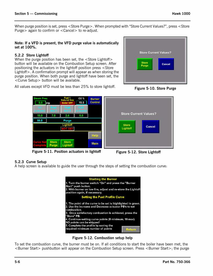
Section 5 — Commissioning Hawk 1000
When purge position is set, press <Store Purge>. When prompted with “Store Current Values?”, press <Store Purge> again to confirm or <Cancel> to re-adjust.
Note: If a VFD is present, the VFD purge value is automatically set at 100%.
5.2.2 Store LightoffWhen the purge position has been set, the <Store Lightoff> button will be available on the Combustion Setup screen. After positioning the actuators in the lightoff position press <Store Lightoff>. A confirmation prompt will appear as when storing the purge position. When both purge and lightoff have been set, the <Curve Setup> button will be available.
All values except VFD must be less than 25% to store lightoff.
5.2.3 Curve SetupA help screen is available to guide the user through the steps of setting the combustion curve:
Figure 5-12. Combustion setup help
To set the combustion curve, the burner must be on. If all conditions to start the boiler have been met, the <Burner Start> pushbutton will appear on the Combustion Setup screen. Press <Burner Start>; the purge
Figure 5-10. Store Purge
Figure 5-11. Position actuators in lightoff Figure 5-12. Store Lightoff
5-6 Part No. 750-366
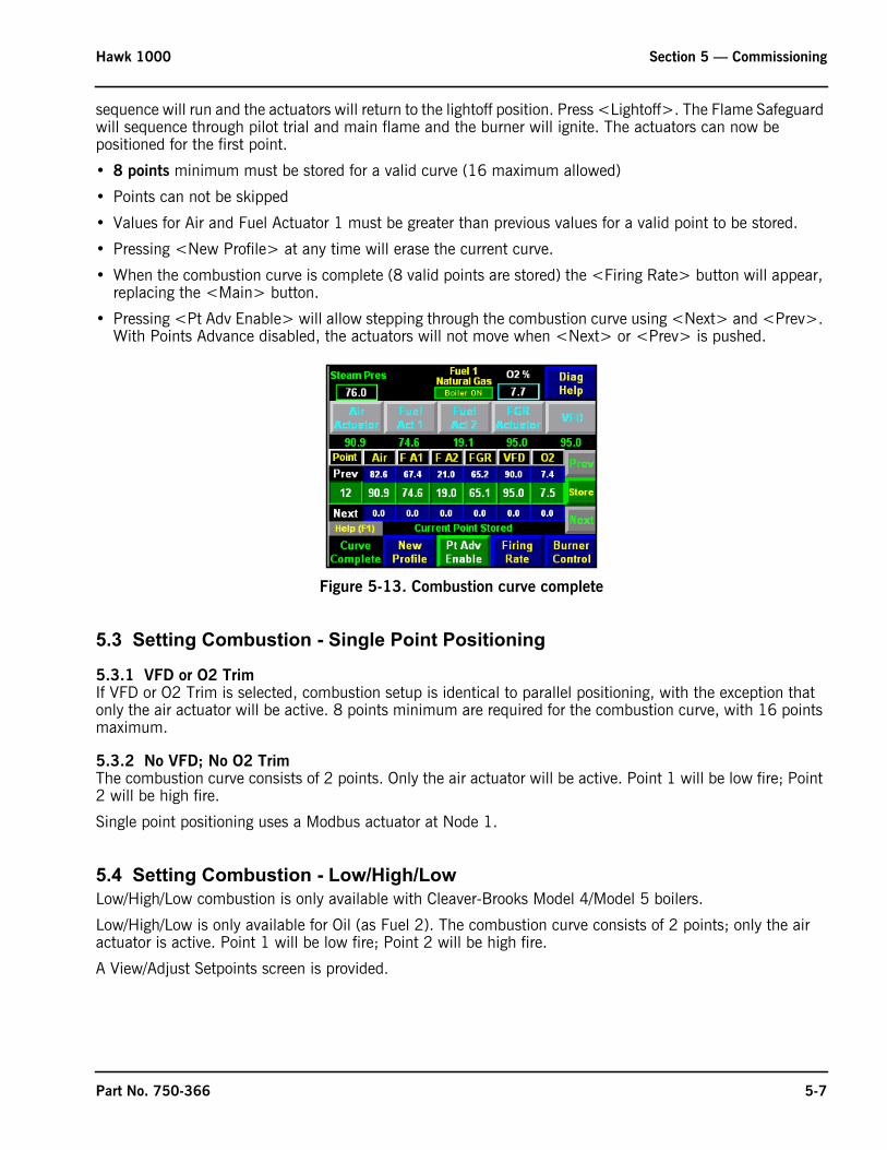
Hawk 1000 Section 5 — Commissioning
sequence will run and the actuators will return to the lightoff position. Press <Lightoff>. The Flame Safeguard will sequence through pilot trial and main flame and the burner will ignite. The actuators can now be positioned for the first point.
• 8 points minimum must be stored for a valid curve (16 maximum allowed)
• Points can not be skipped
• Values for Air and Fuel Actuator 1 must be greater than previous values for a valid point to be stored.
• Pressing <New Profile> at any time will erase the current curve.
• When the combustion curve is complete (8 valid points are stored) the <Firing Rate> button will appear, replacing the <Main> button.
• Pressing <Pt Adv Enable> will allow stepping through the combustion curve using <Next> and <Prev>. With Points Advance disabled, the actuators will not move when <Next> or <Prev> is pushed.
Figure 5-13. Combustion curve complete
5.3 Setting Combustion - Single Point Positioning
5.3.1 VFD or O2 TrimIf VFD or O2 Trim is selected, combustion setup is identical to parallel positioning, with the exception that only the air actuator will be active. 8 points minimum are required for the combustion curve, with 16 points maximum.
5.3.2 No VFD; No O2 TrimThe combustion curve consists of 2 points. Only the air actuator will be active. Point 1 will be low fire; Point 2 will be high fire.
Single point positioning uses a Modbus actuator at Node 1.
5.4 Setting Combustion - Low/High/LowLow/High/Low combustion is only available with Cleaver-Brooks Model 4/Model 5 boilers.
Low/High/Low is only available for Oil (as Fuel 2). The combustion curve consists of 2 points; only the air actuator is active. Point 1 will be low fire; Point 2 will be high fire.
A View/Adjust Setpoints screen is provided.
Part No. 750-366 5-7
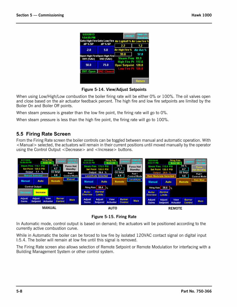
Section 5 — Commissioning Hawk 1000
Figure 5-14. View/Adjust Setpoints
When using Low/High/Low combustion the boiler firing rate will be either 0% or 100%. The oil valves open and close based on the air actuator feedback percent. The high fire and low fire setpoints are limited by the Boiler On and Boiler Off points.
When steam pressure is greater than the low fire point, the firing rate will go to 0%.
When steam pressure is less than the high fire point, the firing rate will go to 100%.
5.5 Firing Rate ScreenFrom the Firing Rate screen the boiler controls can be toggled between manual and automatic operation. With <Manual> selected, the actuators will remain in their current positions until moved manually by the operator using the Control Output <Decrease> and <Increase> buttons.
Figure 5-15. Firing Rate
In Automatic mode, control output is based on demand; the actuators will be positioned according to the currently active combustion curve.
While in Automatic the boiler can be forced to low fire by isolated 120VAC contact signal on digital input I:5.4. The boiler will remain at low fire until this signal is removed.
The Firing Rate screen also allows selection of Remote Setpoint or Remote Modulation for interfacing with a Building Management System or other control system.
MANUAL AUTO REMOTE
5-8 Part No. 750-366

Hawk 1000 Section 5 — Commissioning
Figure 5-16. Remote Signal Fail
In the event of a bad remote signal, an alarm message will appear on the screen and the control will revert to Local/Auto mode.
The <Adjust Gains> button accesses the system PID tuning. Default values are: P=5, I=5, D=0.
Figure 5-17. Adjust Gains
<Adjust Setpoint> allows adjustment of Setpoint 1 and Setpoint 2 (if dual setpoint is configured).
Figure 5-18. Adjust Setpoint
<View Actuator> shows setpoint and feedback signals for all configured actuators.
Part No. 750-366 5-9

Section 5 — Commissioning Hawk 1000
Figure 5-19. View Actuators
The <Manipulate Actuators> button allows the actuators to travel through 0-100% of firing rate to verify all actuators are positioning correctly at the current firing rate. To use this feature, the Burner Switch must be OFF and firing rate must be in MANUAL mode. While manipulating the actuators, output and firing rate are not rate limited.
5.5.1 Remote Setpoint/Remote ModulationIf Remote Setpoint or Remote Modulation is configured, the appropriate display and controls will appear on the Firing Rate screen.
Figure 5-20. Remote Setpoint/Remote Modulation
Remote modulation by digital input is configured. Digital input is on and Remote Mod selected.
Remote modulation by digital input. Digital input is off; firing rate reverts to local control
Remote mod. by Comms
Remote setpoint by Digital Input.
Remote setpoint by Comms.
Remote setpoint by HMI.
Remote mod. by HMI
Remote setpoint by digital input. Digital input is off; setpoint reverts to local control
5-10 Part No. 750-366

Hawk 1000 Section 5 — Commissioning
5.6 Alarms and LimitsAlarms with configurable parameters and firing rate/setpoint limits can be edited from this screen. Configurable items include the following:
5.6.1 High Stack TemperatureSelect Alarm and Shutdown points.
5.6.2 Low O2Select Low O2 Alarm, Shutdown, and Alarm Delay points. Low O2 Alarm only available with selection of an O2 analyzer. Shutdown only available if selected in the System Configuration menu.
5.6.3 Low Steam PressureSelect Low Steam Pressure setpoint and Audible Yes/No. Alarm horn or bell must be available for audible alarms.
5.6.4 Firing Rate Limit, Setpoint Limiting, Remote SP Scaling, Extended Pre-Purge, External Device TimerThe Firing Rate Limit value can be used to limit the maximum control output from the HAWK 1000. A value of zero will not allow the boiler to go above low fire.
Set Point Limiting - The minimum and maximum allowable setpoint values can be set here. The high and low limit points affect the Set Point and the On and Off points on the setpoint screen.
Remote Set Point Scaling - The HAWK 1000 allows a remote 4-20 mA input signal to vary the setpoint. The remote setpoint scaling enables the operator to zero and span the signal. The zero value will correspond to a
remote signal of 4 mA. The span value will correspond to a remote signal of 20 mA. Remote setpoint may be enabled by a remote digital input signal or from the HMI Firing Rate screen.
Extended Pre-Purge Time extends pre-purge by up to 180 seconds.
External Device Timer allows the Start External Device (FAD) Output to remain energized for a period of time (3-60 minutes) after a boiler shutdown.
Figure 5-21. Alarms and Limits - Low O2
Figure 5-22. Alarms and Limits - Low Steam Pressure
Figure 5-23. Alarms and Limits - Firing Rate Limit
Part No. 750-366 5-11

Section 5 — Commissioning Hawk 1000
5.6.5 Mod. Rate Limiter, Max. O2 Correct, Remote Shutdown by Comms.
Modulation rate limiting increases/decreases the rate of change of firing rate output. The value entered is the number of seconds the control output will take to go between 0-100%
Maximum O2 Trim Correction is the value plus or minus that the VFD or Air Actuator can correct (+/- 10% maximum).
Remote Shutdown by Communications allows for remote start/stop of the boiler. If this feature is enabled, the <On Comms Failure...> setting determines what the boiler will do upon a failure of remote communications (shut down or remain in its last state).
Two help screens are available for Remote Shutdown.
5.6.6 Stack Low Temp. Hold
This feature is only available with FGR. Selectable to hold FGR only or FGR and firing rate (FGR & Firing Rate must be selected for 20 ppm or less systems). “FGR Posn w/ Low Stk Temp” must be set for every combustion curve (4 maximum) and must be lower than the FGR low fire point.
If Stack Low Temp. Hold and FGR Only are enabled and the stack temperature is below the “Stack Low Temp Hold” setpoint, the boiler is allowed to modulate while the FGR actuator is forced to the “FGR Posn w/Low Stk Temp” position. When the stack temperature rises above the setpoint for the “Delay Seconds” period, FGR will release and go to the firing rate commanded position.
If Stack Low Temp. Hold and Firing Rate are enabled and the stack temperature is below the “Stack Low Temp Hold” Set Point, the boiler is held at low fire while the FGR actuator is forced to the “FGR Posn w/Low Stk Temp” position. When the stack temperature rises above the set point
Figure 5-24. Alarms and Limits - Mod. Rate Limiter
Figure 5-25. Remote Shutdown Help
REMOTE SHUTDOWN HELP
REMOTE SD HEARTBEAT HELP
Figure 5-26. Alarms and Limits - Stack Low Temp Hold
5-12 Part No. 750-366
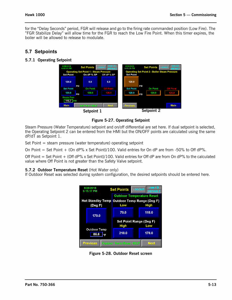
Hawk 1000 Section 5 — Commissioning
for the “Delay Seconds” period, FGR will release and go to the firing rate commanded position (Low Fire). The ”FGR Stabilize Delay” will allow time for the FGR to reach the Low Fire Point. When this timer expires, the boiler will be allowed to release to modulate.
5.7 Setpoints5.7.1 Operating Setpoint
Figure 5-27. Operating Setpoint
Steam Pressure (Water Temperature) setpoint and on/off differential are set here. If dual setpoint is selected, the Operating Setpoint 2 can be entered from the HMI but the ON/OFF points are calculated using the same dP/dT as Setpoint 1.
Set Point = steam pressure (water temperature) operating setpoint
On Point = Set Point + (On dP% x Set Point)/100. Valid entries for On dP are from -50% to Off dP%.
Off Point = Set Point + (Off dP% x Set Point)/100. Valid entries for Off dP are from On dP% to the calculated value where Off Point is not greater than the Safety Valve setpoint.
5.7.2 Outdoor Temperature Reset (Hot Water only)If Outdoor Reset was selected during system configuration, the desired setpoints should be entered here.
Figure 5-28. Outdoor Reset screen
Setpoint 1 Setpoint 2
Part No. 750-366 5-13

Section 5 — Commissioning Hawk 1000
Figure 5-29. Outdoor reset curve
5.7.3 Hot StandbyHot Standby when active will cycle the boiler on if the shell water temperature (steam boilers) or supply water temperature (hot water boilers) drops 5 degrees F below the “Hot Standby Temp”. The boiler will remain at low fire until the shell (supply) water temperature reaches the “Hot Standby Temp” at which time the boiler will turn off. I:5.7 ALFCO must be turned off to initiate Hot Standby.
Hot Standby can be initiated manually by pressing <Force Hot Standby> (on the Firing Rate Screen).
5.7.4 Revert to Pilot (CB 120E only)Revert to Pilot (RTP) reduces cycling by eliminating the purge sequence.
When RTP is initiated the boiler returns to low fire, output O:6.4 is energized, and the Revert to Pilot signal is sent to the flame safeguard. The RTP sequence is managed by the FSG: pilot is energized, and upon proof of pilot the main gas valve de-energizes and the boiler remains on pilot. When demand returns or digital input I:5.7 is ON the main gas valve is energized.
When RTP is on a “Rev to Pilot” indicator will appear on the Overview and Firing Rate screens.
Initiated by process variable
If ‘Initiate by process variable’ is selected, Revert to Pilot is initiated when steam pressure is greater than or equal to “Revert to Pilot Pressure” and de-activated when steam pressure is below the boiler “On Point”.
-60 -40 -20 0 20 40 60 80175
180
185
190
195
200
205
Setpoint
OutdoorTemperature
OUTDOOR RESET CURVE
Set point is linear in relation to the outdoor temperature.Range for outdoor temperature transmitter is 4 ma = -50 deg F, 20 ma = 900 deg F.In this example:Outdoor Temp Range Low = 0 deg FSet Point Range High = 200 deg FOutdoor Temp Range High = 60 deg FSet Point Range Low = 180 deg F
5-14 Part No. 750-366

Hawk 1000 Section 5 — Commissioning
Revert to Pilot Pressure = Off Point - (Revert to Pilot dP% x Off Point) [ensures that the RTP setting is always less than or equal to the boiler off point]
Revert to Pilot Pressure must be greater than the boiler operating Setpoint or boiler On Point, whichever is greater.
Figure 5-30. Revert to Pilot
Initiated by digital input
If ‘Initiate by digital input’ is selected, the above screen will not be shown; Revert to Pilot will be initiated when digital input I:5.7 ALFCO is OFF.
5.8 O2 TrimIf O2 Trim was selected and an analyzer specified during system configuration, the <Flue Gas O2 Control> button will appear on the Main screen.
Figure 5-31. O2 Trim
O2 Trim is accomplished by means of the air actuator, or by the VFD if present (if VFD is in Bypass, the air actuator is used). A manual operating mode is provided for diagnostic or testing purposes.The CB O2 analyzer requires calibration on power up, or if one week has elapsed since the last calibration. If using the Yokogawa analyzer, the PLC will expect a “Sensor OK” input from the analyzer at input I:5.2.Once the O2 sensor is calibrated or “Sensor OK” input is on, the O2 setpoint is captured when setting combustion curves.
Part No. 750-366 5-15

Section 5 — Commissioning Hawk 1000
PID control of O2 Trim is provided. Values can be adjusted by pressing <Adjust Gains>. Defaults are P=3, I=5, and D=0.
Figure 5-32. O2 Calibration
5.9 Drive DataIf a VFD is present, <Drive Data> will display a read-only screen showing drive output and feedback, Low/High/Lightoff settings, and current running frequency.
5.10 Ethernet ConfigurationIn order to configure the Ethernet port, the PLC switch must be in REM and the RUN LED must be GREEN.
Multiple boilers on the same Ethernet network require unique IP addresses. To change a boiler’s configuration, press the desired field in the “Set New Ethernet Configuration” area. If user is logged in at the proper level, a numeric keypad will appear. Enter the new data and press the enter key (or use the PV+ keypad). When finished, go to <Set Enet Config> and when prompted with “Set PLC Ethernet Port Configuration?” press <Yes>.
O2 Calibration Calibration Help Screen
5-16 Part No. 750-366
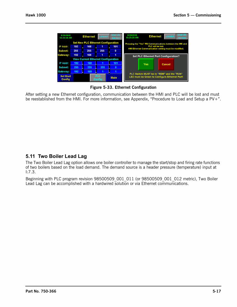
Hawk 1000 Section 5 — Commissioning
Figure 5-33. Ethernet Configuration
After setting a new Ethernet configuration, communication between the HMI and PLC will be lost and must be reestablished from the HMI. For more information, see Appendix, “Procedure to Load and Setup a PV+”.
5.11 Two Boiler Lead LagThe Two Boiler Lead Lag option allows one boiler controller to manage the start/stop and firing rate functions of two boilers based on the load demand. The demand source is a header pressure (temperature) input at I:7.3.
Beginning with PLC program revision 98500509_001_011 (or 98500509_001_012 metric), Two Boiler Lead Lag can be accomplished with a hardwired solution or via Ethernet communications.
Part No. 750-366 5-17

Section 5 — Commissioning Hawk 1000
Figure 5-34. Typical Two Boiler Lead/Lag system (hard wired)
Figure 5-35. Two Boiler Lead/Lag by Communications
If 2 Boiler Lead Lag Master is enabled in the Configuration section, two additional screens (for Lead Lag Setup and Lead Lag Control) will be available.
5-18 Part No. 750-366

Hawk 1000 Section 5 — Commissioning
5.11.1 Lead Lag SetupSelect Modulation - Select Lead Lag (steam boilers only) or Unison modulation.
Select Lead Lag - Select Master boiler as Lead and Slave boiler as Lag, or Master as Lag and Slave as Lead.
Lag Boiler settings:
Start Point - Control output percentage of the Lead boiler at which the “Start delay” timer is activated. Valid values are from “Stop Point” to 100%.
Start Delay - This time delay is activated when Lead boiler control output is greater than “Start Point” setting. After the time delay has expired the Lag boiler is commanded to start. Valid values are from 0 to 600 seconds.
Stop Point - Control output percentage of the Lead boiler at which the “Stop Delay” timer is activated. Valid values are from 0 to “Start Point”.
Stop Delay - This time delay relay is activated when the Lead's boiler control output is less then “Stop Point” setting. After the time delay has expired, the Lag boiler is commanded to stop. Valid values are from 0 to 600 seconds.
Shutdown Delay - This is the length of time that the Lag boiler is allowed to run after the “Stop Delay” has expired. Valid values are from 0 to 600 seconds.
Modulation Start - Control output to the Lead boiler at which the Lag boiler starts modulation. This parameter is only applicable to Lead/Lag modulation. Valid values are from 0 to 100%.
Header Steam Pressure (Water Temp.) settings - Set the Lead Lag Set Point, On Differential, and Off Differential.
Remote Set Point Enable - Select if using a remote set point signal at I2/14.
Sequencing - If enabled, will automatically rotate the Lead and Lag boilers after Number of Days.
If two boiler lead lag master is enabled and is via communications an additional screen will be available to set the IP address of the slave boiler. The IP address of the slave boiler must be entered from the 2 Boiler Slave IP Setup Screen.
Figure 5-37. Slave IP Setup
Figure 5-36. 2 Boiler Lead Lag Setup
SLAVE IP NOT SET SLAVE IP SET
Part No. 750-366 5-19

Section 5 — Commissioning Hawk 1000
5.11.2 Lead Lag Control
The Lead Lag control screen has Auto/Manual controls and graphic displays showing operational data for each boiler and for the Lead Lag System.
Note: In order for either boiler to be part of the lead lag sequence, <Remote> must be selected under “Control Mode” on the boiler’s firing rate screen.
Lead Lag Modulation - The lag boiler starts when the lead boiler’s firing rate signal reaches the Start Point (and the Start Delay has expired). The lag boiler starts modulating after the lead boiler reaches the configured Modulation Start point. The lag boiler is commanded to stop when the lead boiler’s firing rate signal reaches the Stop Point (and the Stop Delay has expired).
In the event of a header sensor failure, master and slave boilers will revert to local firing rate control.
Unison Modulation - Firing rates for both boilers are equal. Hot Water systems must use unison modulation.
5.12 Thermal Shock RoutineTo protect against thermal shock, the Hawk 1000 incorporates a routine to prevent the boiler water temperature from rising too rapidly on a cold startup.
Steam boilers
Thermal shock protection is activated when the boiler water temperature is below 60% of the steam saturation temperature at set point. If the boiler is in thermal shock protection and released for modulation, and water temperature is above the hot standby off temperature*, a timer is activated. The boiler firing rate is incremented once every 126 seconds. Thermal shock is deactivated when boiler water temperature reaches 90% of the saturated temperature at set point.
It will not be re-activated unless temperature drops below 60% of the steam saturation temperature with the fuel valve terminal de-energized, or if the fuel valve has been de-energized for more than 8 hours.
For Hot Water Boilers
Thermal shock protection is activated when actual water temperature is below minimum temperature (150F for Firetube or 120F for FLX). If the boiler is in thermal shock protection and released for modulation, and water temperature is above the hot standby off temperature*, a timer is activated. The boiler firing rate is incremented once every 60 seconds. Thermal shock is deactivated when hot water temperature reaches 90% of set point.
It will not be re-activated until temperature drops below minimum temperature with the fuel valve terminal de-energized, or if the fuel valve has been de-energized for more than 8 hours.
*If fuel valve is energized for more than 1 hour (Steam) or 10 minutes (Hot Water) and water temperature is still below standby temperature setting, firing rate will start ramping up as described.
Figure 5-38. Lead Lag Control
5-20 Part No. 750-366

www.cleaverbrooks.com
Section 6Diagnostics and Troubleshooting
System Monitoring and Diagnostics . . . . . . . . . . . . . . . . . . . . . . . . . . . . . 6-2Boiler Overview . . . . . . . . . . . . . . . . . . . . . . . . . . . . . . . . . . . 6-2Burner Control . . . . . . . . . . . . . . . . . . . . . . . . . . . . . . . . . . . . 6-2System Information . . . . . . . . . . . . . . . . . . . . . . . . . . . . . . . . . 6-3PLC Info . . . . . . . . . . . . . . . . . . . . . . . . . . . . . . . . . . . . . . . . 6-3Diagnostic Screens . . . . . . . . . . . . . . . . . . . . . . . . . . . . . . . . . 6-4PLC I/O Status. . . . . . . . . . . . . . . . . . . . . . . . . . . . . . . . . . . . . 6-4Combustion Curve Data . . . . . . . . . . . . . . . . . . . . . . . . . . . . . . 6-4
Alarms . . . . . . . . . . . . . . . . . . . . . . . . . . . . . . . . . . . . . . . . . . . . . . . . . 6-5Troubleshooting. . . . . . . . . . . . . . . . . . . . . . . . . . . . . . . . . . . . 6-6
PLC Status. . . . . . . . . . . . . . . . . . . . . . . . . . . . . . . . . . . . . . . . . . . . . . . 6-9

Section 6 — Diagnostics and Troubleshooting Hawk 1000
6.1 System Monitoring and Diagnostics6.1.1 Boiler OverviewThe Hawk 1000 has a number of features for monitoring system performance and diagnosing problems.
The Boiler Overview screen shows the primary operating details of the boiler and is accessible from the Main screen.
Figure 6-1. Overview screen
6.1.2 Burner ControlThe Burner Control screen gives details on the installed Flame Safeguard (CB780 or CB120).
Figure 6-2. Burner Control screens
The status of the Flame Safety control is shown as well as the status of the inputs that allow the boiler to start.
The following flame safety status and boiler inputs are shown on the Burner Control screen:Burner Switch - Indicates position of the burner switch.Load Demand - When starting the boiler, there is a load demand if the system pressure (steam) or temperature (hot water) is below the “On Point”. When system Pressure/Temperature exceeds the OFF point, “No Demand”
Burner Control - CB780 Burner Control - CB120
6-2 Part No. 750-366

Hawk 1000 Section 6 — Diagnostics and Troubleshooting
is indicated. When the system Pressure/Temperature drops below the “On Point”, load demand will again be displayed.Limits -This is an indication of the status of the running interlocks on the boiler. External Interlock - Feedback input from external interlock. When there is a load demand, and the burner switch and limits are closed, the HAWK 1000 has isolated contacts (2.5A @ 125VAC) for output to an external interlock device (e.g. fresh air damper, circulating pump). The boiler will start once the external interlock is proven.
Note: The external interlock must be jumped if not used
ALFCO - Assured Low Fire Cut-Off. An external isolated start-stop contact can be provided to shut down the boiler. This contact will drive the boiler to low fire prior to shut down.Note: The ALFCO must be jumped if not used.
6.1.3 System InformationPress <System Information> from the Main screen to access. This screen shows boiler identification information, the currently loaded programs for the PLC and HMI, elapsed time and cycles since last startup, and network address information.
Figure 6-3. System Information
6.1.4 PLC Info
Figure 6-4. PLC Info
This screen duplicates the L24 Status LEDs and in addition shows the current PLC firmware revision, serial number, and PLC switch position.
Part No. 750-366 6-3

Section 6 — Diagnostics and Troubleshooting Hawk 1000
6.1.5 Diagnostic ScreensPress <Diagnostic> on the Main screen for the diagnostic screen menu. Select an item from the menu to show a detailed view of the corresponding program logic. Items in green are TRUE and those in white are FALSE.
6.1.6 PLC I/O StatusThe PLC I/O Status screen shows the status of all PLC inputs and outputs. Digital I/O points indicate On or Off; analog I/O indicate Raw (analog signal in mA or Volts) and Value (corresponding value in engineering units).
6.1.7 Combustion Curve DataThis screen shows the combustion curve for the selected fuel.
Figure 6-5. Diagnostics screen
Figure 6-6. PLC I/O Status
Figure 6-7. Combustion Curve
6-4 Part No. 750-366

Hawk 1000 Section 6 — Diagnostics and Troubleshooting
6.2 AlarmsIf an alarm is active the alarm bell will be visible on all screens:
The bell signals the following conditions depending on its appearance:
Press the alarm bell or <Alarms> from the Main Screen to access the Alarm screen.
This screen can be toggled between <Active Alarms> and <Alarm History>. The Alarm History will store up to 200 alarms. The history can be cleared (password required) by pressing <Clear Alarm History>.
<Alarm Silence> will turn the alarm bell off until another alarm becomes active.
Yellow flashing Warning - alarm not silenced
Yellow solid Warning - alarm silenced
Red flashing Fault - alarm not silenced
Red solid Fault - alarm silenced
Figure 6-8. Alarm Screen
Part No. 750-366 6-5
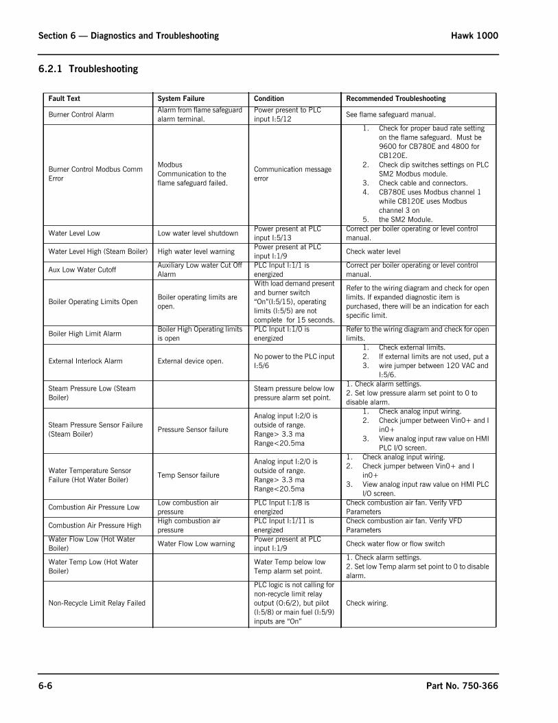
Section 6 — Diagnostics and Troubleshooting Hawk 1000
6.2.1 Troubleshooting
Fault Text System Failure Condition Recommended Troubleshooting
Burner Control AlarmAlarm from flame safeguard alarm terminal.
Power present to PLC input I:5/12
See flame safeguard manual.
Burner Control Modbus Comm Error
ModbusCommunication to the flame safeguard failed.
Communication message error
1. Check for proper baud rate setting on the flame safeguard. Must be 9600 for CB780E and 4800 for CB120E.
2. Check dip switches settings on PLC SM2 Modbus module.
3. Check cable and connectors.4. CB780E uses Modbus channel 1
while CB120E uses Modbus channel 3 on
5. the SM2 Module.
Water Level Low Low water level shutdownPower present at PLC input I:5/13
Correct per boiler operating or level control manual.
Water Level High (Steam Boiler) High water level warning Power present at PLC input I:1/9
Check water level
Aux Low Water CutoffAuxiliary Low water Cut Off Alarm
PLC Input I:1/1 is energized
Correct per boiler operating or level control manual.
Boiler Operating Limits OpenBoiler operating limits are open.
With load demand present and burner switch “On”(I:5/15), operating limits (I:5/5) are not complete for 15 seconds.
Refer to the wiring diagram and check for open limits. If expanded diagnostic item is purchased, there will be an indication for each specific limit.
Boiler High Limit AlarmBoiler High Operating limits is open
PLC Input I:1/0 is energized
Refer to the wiring diagram and check for open limits.
External Interlock Alarm External device open.No power to the PLC input I:5/6
1. Check external limits.2. If external limits are not used, put a 3. wire jumper between 120 VAC and
I:5/6.
Steam Pressure Low (Steam Boiler)
Steam pressure below low pressure alarm set point.
1. Check alarm settings.2. Set low pressure alarm set point to 0 to disable alarm.
Steam Pressure Sensor Failure (Steam Boiler)
Pressure Sensor failure
Analog input I:2/0 is outside of range.Range> 3.3 maRange<20.5ma
1. Check analog input wiring.2. Check jumper between Vin0+ and I
in0+3. View analog input raw value on HMI
PLC I/O screen.
Water Temperature Sensor Failure (Hot Water Boiler)
Temp Sensor failure
Analog input I:2/0 is outside of range.Range> 3.3 maRange<20.5ma
1. Check analog input wiring.2. Check jumper between Vin0+ and I
in0+3. View analog input raw value on HMI PLC
I/O screen.
Combustion Air Pressure LowLow combustion air pressure
PLC Input I:1/8 is energized
Check combustion air fan. Verify VFD Parameters
Combustion Air Pressure HighHigh combustion air pressure
PLC Input I:1/11 is energized
Check combustion air fan. Verify VFD Parameters
Water Flow Low (Hot Water Boiler)
Water Flow Low warning Power present at PLC input I:1/9
Check water flow or flow switch
Water Temp Low (Hot Water Boiler)
Water Temp below low Temp alarm set point.
1. Check alarm settings.2. Set low Temp alarm set point to 0 to disable alarm.
Non-Recycle Limit Relay Failed
PLC logic is not calling for non-recycle limit relay output (O:6/2), but pilot (I:5/8) or main fuel (I:5/9) inputs are “On”
Check wiring.
6-6 Part No. 750-366

Hawk 1000 Section 6 — Diagnostics and Troubleshooting
Recycle Limit Relay Failed
PLC logic is not calling for recycle limit relay output (O:6/0), but pilot (I:5/8) or main fuel (I:5/9) inputs are “On”
Check wiring.
Water Level Signal Failure (Steam Boiler)
Water Level Sensor failure
With water Level option selected Analog input I:2/3 is outside of range.Range> 3.3 maRange<20.5ma
1. Check analog input wiring.2. Measure analog input.3. Check jumper between Vin0+ and I
in0+4. View analog input Raw value on the HMI
PLC I/O status screen.
Remote Modulation Signal Failure
Remote Mod Signal Failed
With remote mod by analog, CB Master LLag, or 2 Boiler LLag Slave option selected, Analog input I:2/3 is outside of range.Range> 3.3 maRange<20.5ma
With 2 Boiler LLag Slave by comms selected main Header loss is via communication
1. Check analog input wiring.2. Measure analog input.3. Check jumper between Vin0+ and I
in0+4. View analog input Raw value on the HMI
PLC I/O status screen.5. Verify System Configuration settings on
HMI
1. Verify that the 2 Boiler Lead Lag Master Header Transmitter analog input I:7.3 is OK.
Remote Set Point Signal FailureRemote Setpoint Signal Failed
With remote setpoint option selected Analog input I:2/3 is outside of range.Range> 3.3 maRange<20.5ma
1. Check analog input wiring.2. Measure analog input.3. Check jumper between Vin0+ and I
in0+4. View analog input Raw value on the
HMI PLC I/O status screen.5. Verify System Configuration settings on
HMI.
Low Oxygen in Flue Gas Low Oxygen level in flue gas O2 level below alarm set point or below 0.5%.
1. Check combustion.2. From system config screen check if
correct O2 analyzer is selected.3. Check analyzer wiring.4. Verify O2 Calibration voltage if CB
analyzer5. is selected.
Low Oxygen in Flue Gas Shutdown
Low Low Oxygen level in flue gas
O2 level below Shutdown set point.
1. Check combustion.2. From system config screen check if
correct O2 analyzer is selected.3. Check analyzer wiring.4. Verify O2 Calibration voltage if CB
analyzer5. is selected.
O2 Sensor Calibration FailedO2 analyzer calibration failed (Only applicable to CB O2 analyzer)
O2 signal (input I:7/2) must be between 4 and 6.5 VDC during calibration
1. Check wiring.Repeat calibration.
Fuel 1 Pressure Low Low fuel1 gas pressurePLC Input I:1/2 is energized (Fuel 1 is Selected)
Check gas pressure regulator.
Fuel 1 Pressure High High fuel1 gas pressurePLC Input I:1/3 is energized (Fuel 1 is Selected)
Check gas pressure regulator.
Fault Text System Failure Condition Recommended Troubleshooting
Part No. 750-366 6-7

Section 6 — Diagnostics and Troubleshooting Hawk 1000
No Fuel Selected Fuel is not selected
With burner switch “On” PLC Input I:5/15 energized, PLC inputs I:5/10 and I:5/11 are de-energized or are both energized.
Check wiring. Depending on the Number of Fuels selected either, None of the Fuel Selected PLC inputs are on, or more than one Fuel Selected PLC inputs are on.
Fuel 2 Temperature Low Low heavy oil temperaturePLC Input I:1/2 is energized (Fuel 2 is Selected)
Check oil temperature.
Fuel 2 Temperature High High heavy oil temperaturePLC Input I:1/3 is energized (Fuel 2 is Selected)
Check oil temperature.
Fuel 2 Pressure Low Low fuel oil pressurePLC Input I:1/4 is energized
Check oil pressure.
Fuel 2 Pressure High High fuel oil pressurePLC Input I:1/5 is energized
Check oil pressure.
Oil Drawer Switch Not MadeFuel oil gun is not in position
PLC Input I:1/6 is energized
Check oil gun position.
Atomizing Air Pressure Low Low atomizing air pressurePLC Input I:1/7 is energized
Check atomizing air compressor
Stack Temperature High AlarmHigh flue gas temperature at the boiler outlet.
Flue gas temperature I:2/1 is above high temperature alarm setting.
1. Check for proper alarm setting.2. Deposits on the pressure vessel
surface.3. Faulty temperature sensor.
Stack Temperature High Shutdown
High flue gas temperature at the boiler outlet.
Flue gas temperature I:2/1) is above high temperature shutdown setting
1. Check for proper shutdown setting.2. Deposits on the pressure vessel
surface.3. Faulty temperature sensor.
Aux 1 – “User Defined Alarm”PLC Input I:1/13 is energized
1. Job Specific User defined alarm.2. Defined on system config screen
Aux 2 – “User Defined Alarm”PLC Input I:1/14 is energized
1. Job Specific User defined alarm.2. Defined on system config screen
Aux 3 – “User Defined Alarm”PLC Input I:1/15 is energized
1. Job Specific User defined alarm.2. Defined on system config screen
Air/xxx Actuator Position Deviation
Combustion air actuator failed to go to position
Difference between commanded and actual position is not within acceptable limits.
1. Check air damper for binding.2. Check alignment.3. Check wiring connections.4. Replace actuator.
Air/xxx Actuator Feedback LowAir actuator position feedback is low
Actuator feedback signal is lower than -2.0%
1. Check air damper for binding.2. Check alignment.3. Check wiring connections.4. Re-commission actuator (Fuel curve
will be lost).5. Replace actuator
Fault Text System Failure Condition Recommended Troubleshooting
6-8 Part No. 750-366

Hawk 1000 Section 6 — Diagnostics and Troubleshooting
6.3 PLC Status The L24E has a bank of multi-state LEDs to indicate the controller’s operating status and communication activities. See tables below.
Table 1: PLC Status LEDs
Indicator Status DescriptionRUN Off The controller is in Program or Test mode.
Green The controller is in Run mode.
FORCE Off No tags contain I/O force values. I/O forces are inactive (disabled).
Yellow I/O forces are active (enabled). I/O force values may or may not exist.
Flashing yellow One or more input or output addresses have been forced to an On or Off condition, but the forces have not been enabled.
I/O Off The controller does not contain a project.
Green The controller is communicating with all of the devices in its I/O configuration.
Flashing green One or more devices in the I/O configuration of the controller are not responding.
Flashing red One of the following conditions exists:• The controller is not communicating with any devices.• A fault has occurred on the controller
OK Off No power is applied.
Green The controller is OK.
Flashing green The controller is storing a project to or loading a project from the SD card.
Red The controller detected a nonrecoverable major fault and cleared the project from memory.
Flashing red One of the following:• The controller requires a firmware update.• A major recoverable fault occurred on the controller.• A nonrecoverable major fault occurred on the controller and cleared the program from memory. • A controller firmware update is in process.
Dim green to red Save to Flash at power-down.
Table 2: PLC Communication LEDs
Indicator Status Description
Ethernet Network Status (NS)
Off The port is not initialized; it does not have an IP address and is operating in BOOTP or DHCP mode.
Green The port has an IP address and CIP connections are established.
Flashing green The port has an IP address, but no CIP connections are established.
Red The port has detected that the assigned IP address is already in use.
Flashing red/green The port is performing its power-up self test.
Part No. 750-366 6-9
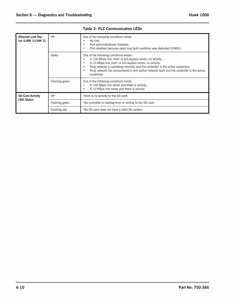
Section 6 — Diagnostics and Troubleshooting Hawk 1000
Ethernet Link Sta-tus (LINK 1/LINK 2)
Off One of the following conditions exists:• No link.• Port administratively disabled.• Port disabled because rapid ring fault condition was detected (LINK2).
Green One of the following conditions exists:• A 100 Mbps link (half- or full-duplex) exists, no activity.• A 10 Mbps link (half- or full-duplex) exists, no activity.• Ring network is operating normally and the controller is the active supervisor.• Ring network has encountered a rare partial network fault and the controller is the active
supervisor.
Flashing green One of the following conditions exists:• A 100 Mbps link exists and there is activity.• A 10 Mbps link exists and there is activity.
SD Card Activity (SD) Status
Off There is no activity to the SD card.
Flashing green The controller is reading from or writing to the SD card.
Flashing red The SD card does not have a valid file system.
Table 2: PLC Communication LEDs
6-10 Part No. 750-366

Section 7Parts
PLC, I/O, HMI
ACTUATORS
MISC.
Qty Part Number Description1 880-06780-000 Hawk 1000 Kit1 833-10039-000 PLC Processor
1 833-06001-000 6 Inch PV+ 7 Touch Screen
1 833-02842-000 Digital Input Module
1 833-02872-000 Relay Module
1 833-03099-000 Modbus Module SM2
2 826-00111-000 Ethernet Cable
1 832-03957-000 Power Supply120 Watt
1 832-02037-000 Power Supply 240 Watt use w/ CB O2 Trim
Qty Part Number Description1 945-00259-000 Modbus FX04-1, 3 ft-lb (4 N-m)
(Use on Fuel and FGR valves, except in High Torque applications)
1 945-00260-000 Modbus FX20-1, 15 ft-lb (20 N-m) (Use On Combustion Air Damper, except in High Torque applications)
1 945-00261-000 Modbus FX50-1, 37 ft-lb (50 N-m)
600” 826-00205-000 Cable, 5 conductor,18 AWG
826-00206-000 Connector, female, straight, 7/8” screw connection - Two required per actuator
Qty Part Number Description1 833-02835-000 1769-IF4 Analog Current Input Module (req. w/ O2 Trim, VFD, or Combustion Air Temp option)
1 833-10116-000 9300-ENA Ethernet Appliance Router
1 817-05166-000 Temperature Sensor, 8" Probe, -50-900 Deg F
1 833-09181-000 Ethernet Switch, Rockwell Stratix 5 Port, 1783-US05T
1 833-09163-000 Ethernet Switch, Rockwell Stratix, 8 Port, 1783-US08T
1
1 817-05166-000 Temperature Sensor, 8" Probe, -50-900 Deg F
1 008-02998-000 Transmitter mounting, Outdoor Reset
1 836-00627-000 Bundled Kit - Gas Oil Selector
www.cleaverbrooks.com

Section 7 — Parts Hawk 1000
FSG
STEAM TRANSMITTERS
Qty Part Number Description880-02117-000 CB-780E w / IR Scanner Kit
1 833-03517-000 CB-780E Programmer
1 833-02725-000 Wiring Sub-Base
1 833-03495-000 Infared Amplifier
1 833-02730-000 Purge Timer Card
1 817-04133-000 Scanner IR 817-1742
880-02118-000 CB-780E w / UV Scanner Kit1 833-03517-000 CB-780E Programmer
1 833-02725-000 Wiring Sub-Base
1 833-02724-000 U.V. Amplifier
1 833-02730-000 Purge Timer Card
1 817-01743-000 Flame Detector UV
880-02097-000 CB-120E w / IR Scanner Kit1 833-03708-000 Chassis/Amplifier
1 833-03153-000 Wiring Sub-Base open with terminal block
1 833-03143-000 Programmer
1 833-03151-000 Display
1 833-03516-000 ED-512 communications cable 4 foot long
1 817-01933-000 IR Scanner 817-2261
880-02096-000 CB-120E w / UV Scanner Kit1 833-03135-000 Chassis/Amplifier
1 833-03153-000 Wiring Sub-Base open with terminal block
1 833-03143-000 Programmer
1 833-03151-000 Display
1 833-03516-000 ED-512 communications cable 4 foot long
1 817-02262-000 UV Detector
Qty Part Number Description1 817-04866-000 E&H PMC131-A22F1Q4H
1 817-00001-000 E&H PMC131-A22F1Q4N
1 817-04867-000 E&H PMC131-A22F1Q4R
1 817-09908-000 E&H PMC131-A22F1Q4S
1 817-09909-000 E&H PMC131-A22F1Q4T
Steam Transmitters (Optional)
1 817-04873-000 PMP51-1CQW9/0 (includes Isolation Valve)
1 817-00002-000 PMP51-1R5E5/0 (includes Isolation Valve)
1 817-04874-000 PMP51-1JAN0/0 (includes Isolation Valve)
1 817-04875-000 PMP51-E9K7/115 (includes Isolation Valve)
1 817-04876-000 PMP51-E9K7/101 (Specify Range) (includes Valve)
1 817-04877-000 PMP51-E9K7/139 (Specify Range) (includes Valve)
1 817-04878-000 PMP51-E9K7/125 (Specify Range) (includes Valve)
1 817-09768-000 PMP51-E9K7/142 (includes Isolation Valve)
1 817-05429-000 St boiler shell temp - NON HART 2.5" Immersion Length Carbon Steel Thermowell, no LCD Display1 817-05430-000 St boiler shell temp - HART 2" Immersion Length Carbon Steel Thermowell, LCD Display
7-2 Part No. 750-366
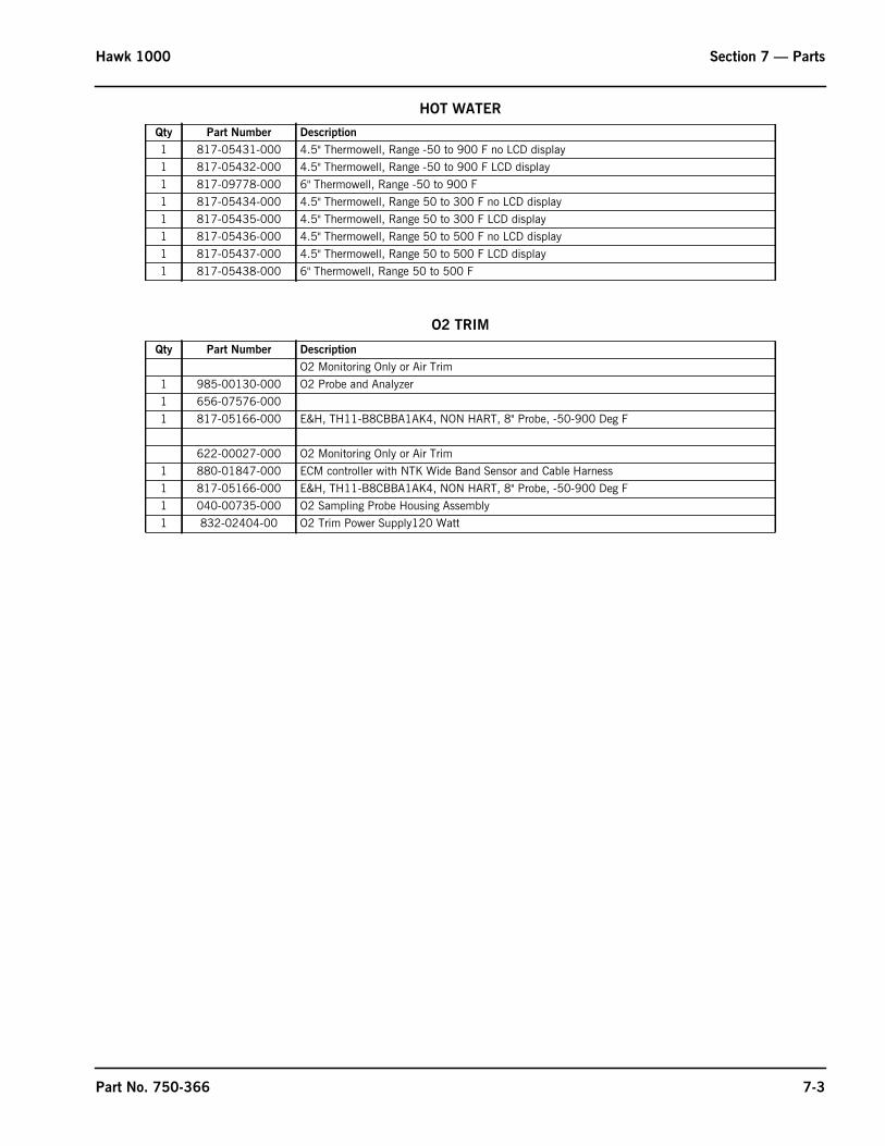
Hawk 1000 Section 7 — Parts
HOT WATER
O2 TRIM
Qty Part Number Description1 817-05431-000 4.5" Thermowell, Range -50 to 900 F no LCD display
1 817-05432-000 4.5" Thermowell, Range -50 to 900 F LCD display
1 817-09778-000 6" Thermowell, Range -50 to 900 F
1 817-05434-000 4.5" Thermowell, Range 50 to 300 F no LCD display
1 817-05435-000 4.5" Thermowell, Range 50 to 300 F LCD display
1 817-05436-000 4.5" Thermowell, Range 50 to 500 F no LCD display
1 817-05437-000 4.5" Thermowell, Range 50 to 500 F LCD display
1 817-05438-000 6" Thermowell, Range 50 to 500 F
Qty Part Number DescriptionO2 Monitoring Only or Air Trim
1 985-00130-000 O2 Probe and Analyzer
1 656-07576-000
1 817-05166-000 E&H, TH11-B8CBBA1AK4, NON HART, 8" Probe, -50-900 Deg F
622-00027-000 O2 Monitoring Only or Air Trim
1 880-01847-000 ECM controller with NTK Wide Band Sensor and Cable Harness
1 817-05166-000 E&H, TH11-B8CBBA1AK4, NON HART, 8" Probe, -50-900 Deg F
1 040-00735-000 O2 Sampling Probe Housing Assembly
1 832-02404-00 O2 Trim Power Supply120 Watt
Part No. 750-366 7-3

Section 7 — Parts Hawk 1000
7-4 Part No. 750-366

Hawk 1000 APPENDIX A
APPENDIX A — HAWK 1000 MASTER TAG LIST
Grayed out items not applicable to Hawk 1000
FPC-N34 Modbus FPC-N35PLC Tagname
Point Name BACnet Data Type
BACnet Object Id
N2 Data Type
N2 Point Address
Modbus Register
Data Type Lon Name Lon SNVT Type
AB[0].0 Drive Fault BI 1 DI 1 10001 Boolean nvoDrvFlt_XXX SNVT_switchAB[0].1 Modbus Comm Error BI 2 DI 2 10002 Boolean nvoModCmEr_XXX SNVT_switchAB[0].2 Lo Water BI 3 DI 3 10003 Boolean nvoLoater_XXX SNVT_switchAB[0].3 Burner Control Alm BI 4 DI 4 10004 Boolean nvoBrnCtrAlm_XXX SNVT_switchAB[0].4 Boiler Limits Open BI 5 DI 5 10005 Boolean nvoBlrLimOpn_XXX SNVT_switchAB[0].5 Hi Stack Temp Alm BI 6 DI 6 10006 Boolean nvoHiStkTpAl_XXX SNVT_switchAB[0].6 Hi Stack Temp Shutdown BI 7 DI 7 10007 Boolean nvoHiStTpShd_XXX SNVT_switchAB[0].7 External Interlock BI 8 DI 8 10008 Boolean nvoExtIntrlk_XXX SNVT_switchAB[0].8 I/O module fault BI 9 DI 9 10009 Boolean nvoIOModFlt_XXX SNVT_switchAB[0].9 Steam Sensor Fail BI 10 DI 10 10010 Boolean nvoStmSenFl_XXX SNVT_switchAB[0].10 Air Actuator Out Of Pos Alm BI 11 DI 11 10011 Boolean nvoArAcPosAl_XXX SNVT_switchAB[0].11 NG Actuator Out Of Pos Alm BI 12 DI 12 10012 Boolean nvoNGAcPosAl_XXX SNVT_switchAB[0].12 F/A Ratio Controller Fault BI 13 DI 13 10013 Boolean nvoFARatCtFl_XXX SNVT_switchAB[0].13 No Fuel Selected BI 14 DI 14 10014 Boolean nvoNoFlSel_XXX SNVT_switchAB[0].14 Lo ControlLogix Battery BI 15 DI 15 10015 Boolean nvoLoPLCBat_XXX SNVT_switchAB[0].15 Non Recycle Limit Relay Fail BI 16 DI 16 10016 Boolean nvoNoRcLmRlF_XXX SNVT_switchAB[1].0 Recyle Limit Relay Fail BI 17 DI 17 10017 Boolean nvoRecLmRlFl_XXX SNVT_switchAB[1].1 Remote Modulation Signal Fail BI 18 DI 18 10018 Boolean nvoRemMdSgFl_XXX SNVT_switchAB[1].2 Header Pressure Sensor Fail BI 19 DI 19 10019 Boolean nvoHdPrSnFl_XXX SNVT_switchAB[1].3 Temperature Channel 0-5 Failure BI 20 DI 20 10020 Boolean nvoTpCh0_5Fl_XXX SNVT_switchAB[1].4 Lo O2 Alm BI 21 DI 21 10021 Boolean nvoLoO2Alm_XXX SNVT_switchAB[1].5 Hi Limit Alm BI 22 DI 22 10022 Boolean nvoHiLimAlm_XXX SNVT_switchAB[1].6 ALWCO BI 23 DI 23 10023 Boolean nvoALWCO_XXX SNVT_switchAB[1].7 Lo Gas Pressure/Lo Oil Temp BI 24 DI 24 10024 Boolean nvoLoGsPrOTp_XXX SNVT_switchAB[1].8 Hi Gas Pressure/Hi Oil Temp BI 25 DI 25 10025 Boolean nvoHiGsPrOTp_XXX SNVT_switchAB[1].9 Lo Oil Pressure BI 26 DI 26 10026 Boolean nvoLoOilPrs_XXX SNVT_switchAB[1].10 Hi Oil Pressure BI 27 DI 27 10027 Boolean nvoHiOilPrs_XXX SNVT_switchAB[1].11 Oil Drawer Switch Not Made BI 28 DI 28 10028 Boolean nvoOilDrwrSw_XXX SNVT_switchAB[1].12 Lo Atomizing Air Pressure BI 29 DI 29 10029 Boolean nvoLoAtmArPr_XXX SNVT_switchAB[1].13 Lo Combustion Air Pressure BI 30 DI 30 10030 Boolean nvoLoComArPr_XXX SNVT_switchAB[1].14 AUX Alm 1 BI 31 DI 31 10031 Boolean nvoAUXAlm1_XXX SNVT_switchAB[1].15 AUX Alm 2 BI 32 DI 32 10032 Boolean nvoAUXAlm2_XXX SNVT_switchAB[2].0 Blower On BI 33 DI 33 10033 Boolean nvoBlwOn_XXX SNVT_switchAB[2].1 Purge Input BI 34 DI 34 10034 Boolean nvoPrgIn_XXX SNVT_switchAB[2].2 Release To Modulate Input BI 35 DI 35 10035 Boolean nvoRel2ModIn_XXX SNVT_switchAB[2].3 Lo Fire Switch BI 36 DI 36 10036 Boolean nvoLoFirSw_XXX SNVT_switchAB[2].4 Hi Fire Switch BI 37 DI 37 10037 Boolean nvoHiFirSw_XXX SNVT_switchAB[2].5 Ready to start/Limits Closed BI 38 DI 38 10038 Boolean nvoRdy2Str_XXX SNVT_switchAB[2].6 External Start Interlock BI 39 DI 39 10039 Boolean nvoExtStInlk_XXX SNVT_switchAB[2].7 ALFCO BI 40 DI 40 10040 Boolean nvoALFCO_XXX SNVT_switchAB[2].8 Pilot BI 41 DI 41 10041 Boolean nvoPilot_XXX SNVT_switchAB[2].9 Main Fuel Valve Open BI 42 DI 42 10042 Boolean nvoMnFlVlvOp_XXX SNVT_switchAB[2].10 Fuel 1 Selected BI 43 DI 43 10043 Boolean nvoFl1Sel_XXX SNVT_switchAB[2].11 Fuel 2 Selected BI 44 DI 44 10044 Boolean nvoFl2Sel_XXX SNVT_switchAB[2].12 Heart Beat To BMS BI 45 DI 45 10045 Boolean nvoHrtBtBMS_XXX SNVT_switchAB[2].13 LWCO Shutdown BI 46 DI 46 10046 Boolean nvoLWCOShdn_XXX SNVT_switchAB[2].14 Remote Enable Input BI 47 DI 47 10047 Boolean nvoRmEnblInp_XXX SNVT_switchAB[2].15 Burner Switch BI 48 DI 48 10048 Boolean nvoBrnSw_XXX SNVT_switchAB[3].0 Recycle Limit Relay BI 49 DI 49 10049 Boolean nvoRecLimRel_XXX SNVT_switchAB[3].1 External Device Start BI 50 DI 50 10050 Boolean nvoExtDevSt_XXX SNVT_switchAB[3].2 Non Recycle Limit Relay BI 51 DI 51 10051 Boolean nvoNoRecLmRl_XXX SNVT_switchAB[3].3 Drive to Lo Fire (FARC) BI 52 DI 52 10052 Boolean nvoDrv2LoFir_XXX SNVT_switchAB[3].4 Start Slave Blr (2 Blr LL) BI 53 DI 53 10053 Boolean nvoStrtSlvBl_XXX SNVT_switchAB[3].5 Load Demand Output BI 54 DI 54 10054 Boolean nvoLdDemOut_XXX SNVT_switchAB[3].6 Alm Output BI 55 DI 55 10055 Boolean nvoAlmOut_XXX SNVT_switchAB[3].7 Boiler Ready (LL) BI 56 DI 56 10056 Boolean nvoBlrRdyLL_XXX SNVT_switchAB[3].8 Boiler Load Demand BI 57 DI 57 10057 Boolean nvoBlrLdDem_XXX SNVT_switchAB[3].9 Firing Rate Remote/Llag BI 58 DI 58 10058 Boolean nvoFrRatRmLL_XXX SNVT_switchAB[3].10 Firing Rate Manual BI 59 DI 59 10059 Boolean nvoFirRatMan_XXX SNVT_switchAB[3].11 Firing Rate Auto BI 60 DI 60 10060 Boolean nvoFrRatAuto_XXX SNVT_switchAB[3].12 Hot Stand By BI 61 DI 61 10061 Boolean nvoHotStndBy_XXX SNVT_switchAB[3].13 Warm Up BI 62 DI 62 10062 Boolean nvoWarmUp_XXX SNVT_switchAB[3].14 Fuel 3 Selected BI 63 DI 63 10063 Boolean nvoFl3Sel_XXX SNVT_switchAB[3].15 Aux Alm 3 BI 64 DI 64 10064 Boolean nvoAuxAlm3_XXX SNVT_switchAB[4].0 Steam or Hot Water 1 = Steam BI 65 DI 65 10065 Boolean nvoStm_HWtr_XXX SNVT_switchAB[4].1 Level Master Present BI 66 DI 66 10066 Boolean nvoLvlMstPrs_XXX SNVT_switchAB[4].2 Variable Speed Drive Present BI 67 DI 67 10067 Boolean nvoVarSpDrPr_XXX SNVT_switchAB[4].3 Economizer Present BI 68 DI 68 10068 Boolean nvoEcPrs_XXX SNVT_switchAB[4].4 Combustion Air Temp Present BI 69 DI 69 10069 Boolean nvoCmArTpPrs_XXX SNVT_switchAB[4].5 Economizer Inlet FW Sensor Present BI 70 DI 70 10070 Boolean nvoEInFwSnPr_XXX SNVT_switchAB[4].6 O2 Analyzer Present BI 71 DI 71 10071 Boolean nvoO2AnlzrPr_XXX SNVT_switchAB[4].7 Feedwater or Return Temp Present BI 72 DI 72 10072 Boolean nvoFdWRtTpPr_XXX SNVT_switchAB[4].8 Outdoor Reset Selected BI 73 DI 73 10073 Boolean nvoOutResSel_XXX SNVT_switchAB[4].9 Parallel Posing Selected BI 74 DI 74 10074 Boolean nvoParPosSel_XXX SNVT_switchAB[4].10 Two Boiler Lead Lag Master Select BI 75 DI 75 10075 Boolean nvo2BLLMstSl_XXX SNVT_switchAB[4].11 Two Boiler Lead Lag Slave Select BI 76 DI 76 10076 Boolean nvo2BLLSlvSl_XXX SNVT_switch
Part No. 750-366 A-1
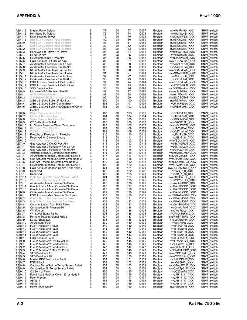
APPENDIX A Hawk 1000
AB[4].12 Master Panel Select BI 77 DI 77 10077 Boolean nvoMstPnlSel_XXX SNVT_switchAB[4].13 Hot Stand By Select BI 78 DI 78 10078 Boolean nvoHotStbySl_XXX SNVT_switchAB[4].14 Dual Setpoint Select BI 79 DI 79 10079 Boolean nvoDualSPSel_XXX SNVT_switchAB[4].15 Slot 8 Ch 0 Analog Input Selected BI 80 DI 80 10080 Boolean nvoSlCh0AISl_XXX SNVT_switchAB[5].0 Slot 8 Ch 1 Analog Input Selected BI 81 DI 81 10081 Boolean nvoSlCh1AISl_XXX SNVT_switchAB[5].1 Slot 8 Ch 2 Analog Input Selected BI 82 DI 82 10082 Boolean nvoSlCh2AISl_XXX SNVT_switchAB[5].2 Slot 8 Ch 3 Analog Input Selected BI 83 DI 83 10083 Boolean nvoSlCh3AISl_XXX SNVT_switchAB[5].3 Honeywell or Fireye 1 = Fireye BI 84 DI 84 10084 Boolean nvoHnywFreye_XXX SNVT_switchAB[5].4 Hi Water Alm BI 85 DI 85 10085 Boolean nvoHiWtrAlm_XXX SNVT_switchAB[5].5 Oil Actuator Out Of Pos Alm BI 86 DI 86 10086 Boolean nvoOlAcPsAlm_XXX SNVT_switchAB[5].6 FGR Actuator Out Of Pos Alm BI 87 DI 87 10087 Boolean nvoFGRAcPsAl_XXX SNVT_switchAB[5].7 Air Actuator Feedback Fail Lo Alm BI 88 DI 88 10088 Boolean nvoAAcFdLoAl_XXX SNVT_switchAB[5].8 Air Actuator Feedback Fail Hi Alm BI 89 DI 89 10089 Boolean nvoAAcFdHiAl_XXX SNVT_switchAB[5].9 NG Actuator Feedback Fail Lo Alm BI 90 DI 90 10090 Boolean nvoNGAFdLoAl_XXX SNVT_switchAB[5].10 NG Actuator Feedback Fail Hi Alm BI 91 DI 91 10091 Boolean nvoNGAFdHiAl_XXX SNVT_switchAB[5].11 Oil Actuator Feedback Fail Lo Alm BI 92 DI 92 10092 Boolean nvoOilFdLoAl_XXX SNVT_switchAB[5].12 Oil Actuator Feedback Fail Hi Alm BI 93 DI 93 10093 Boolean nvoOilFdHiAl_XXX SNVT_switchAB[5].13 FGR Actuator Feedback Fail Lo Alm BI 94 DI 94 10094 Boolean nvoFGRFdLoAl_XXX SNVT_switchAB[5].14 FGR Actuator Feedback Fail Hi Alm BI 95 DI 95 10095 Boolean nvoFGRFdHiAl_XXX SNVT_switchAB[5].15 VSD Deviation Alm BI 96 DI 96 10096 Boolean nvoVSDDevAlm_XXX SNVT_switchAB[6].0 Increase MSG Register Size Bit BI 97 DI 97 10097 Boolean nvoIncMSGReg_XXX SNVT_switchAB[6].1 Air/Fuel Deviation Alm BI 98 DI 98 10098 Boolean nvoArFlDevAl_XXX SNVT_switchAB[6].2 2nd Stage CEC Economizer Selected BI 99 DI 99 10099 Boolean nvo2StCECEcS_XXX SNVT_switchAB[6].3 2 Brl L-L Slave Boiler IP Not Set BI 100 DI 100 10100 Boolean nvoFl3AcPsAl_XXX SNVT_switchAB[6].4 2 Brl L-L Slave Boiler Comm Error BI 101 DI 101 10101 Boolean nvoFl3AFdLoA_XXX SNVT_switchAB[6].5 2 Brl L-L Slave Boiler Not Capable of Comm
ControlBI 102 DI 102 10102 Boolean nvoFl3AFdHiA_XXX SNVT_switch
AB[6].6 Stack Pressure Input Fail BI 103 DI 103 10103 Boolean nvoStkPrInFl_XXX SNVT_switchAB[6].7 Hi Stack Pressure Alm BI 104 DI 104 10104 Boolean nvoHiStkPrAl_XXX SNVT_switchAB[6].8 Stack Damper Not Open Alm BI 105 DI 105 10105 Boolean nvoStDpNtOAl_XXX SNVT_switchAB[6].9 O2 Calibration Failed BI 106 DI 106 10106 Boolean nvoO2ClRtFld_XXX SNVT_switchAB[6].10 Lo Steam Pressure/Water Temp Alm BI 107 DI 107 10107 Boolean nvoLoStPWTAl_XXX SNVT_switchAB[6].11 Processor Test Fail Alm BI 108 DI 108 10108 Boolean nvoPrTstFlAl_XXX SNVT_switchAB[6].12 O2 Trim Internal Alm BI 109 DI 109 10109 Boolean nvoO2TrmInAl_XXX SNVT_switchAB[6].13 Firetube or Flextube 1 = Flextube BI 110 DI 110 10110 Boolean nvoFir_FlxTb_XXX SNVT_switchAB[6].14 Reserved for Cleaver Brooks BI 111 DI 111 10111 Boolean nvoAB_6_14_XXX SNVT_switchAB[6].15 VSD Limits Internal Alm BI 112 DI 112 10112 Boolean nvoVSDLmInAl_XXX SNVT_switchAB[7].0 Gas Actuator 2 Out Of Pos Alm BI 113 DI 113 10113 Boolean nvoGsAc2PsAl_XXX SNVT_switchAB[7].1 Gas Actuator 2 Feedback Fail Lo Alm BI 114 DI 114 10114 Boolean nvoGsAc2LoAl_XXX SNVT_switchAB[7].2 Gas Actuator 2 Feedback Fail Hi Alm BI 115 DI 115 10115 Boolean nvoGsAc2HiAl_XXX SNVT_switchAB[7].3 Actuator Modbus Communication Error BI 116 DI 116 10116 Boolean nvoAcModCmEr_XXX SNVT_switchAB[7].4 Air Actuator Modbus Comm Error Node 1 BI 117 DI 117 10117 Boolean nvoAAcMdCEr1_XXX SNVT_switchAB[7].5 Gas Actuator Modbus Comm Error Node 2 BI 118 DI 118 10118 Boolean nvoGsAMdCEr2_XXX SNVT_switchAB[7].6 Gas Act 2 Modbus Comm Error Node 3 BI 119 DI 119 10119 Boolean nvoGsA2MdCE3_XXX SNVT_switchAB[7].7 Oil Actuator Modbus Comm Error Node 5 BI 120 DI 120 10120 Boolean nvoOAcMdCEr5_XXX SNVT_switchAB[7].8 FGR Actuator Modbus Comm Error Node 7 BI 121 DI 121 10121 Boolean nvoFGRAMdCE7_XXX SNVT_switchAB[7].9 Reserved BI 122 DI 122 10122 Boolean nvoAB_7_9_XXX SNVT_switchAB[7].10 Reserved BI 123 DI 123 10123 Boolean nvoAB_7_10_XXX SNVT_switchAB[7].11 2nd Stg Outlet Wtr Temp Sensor Failed BI 124 DI 124 10124 Boolean nvo2StOtWTSF_XXX SNVT_switchAB[7].12 Wtr Temp Second Stg Out Hi BI 125 DI 125 10125 Boolean nvoWT2StOtHi_XXX SNVT_switchAB[7].13 Air Actuator Man Override Btn Press BI 126 DI 126 10126 Boolean nvoAAcMnOBPr_XXX SNVT_switchAB[7].14 Gas Actuator 1 Man Override Btn Press BI 127 DI 127 10127 Boolean nvoGAc1MOBPr_XXX SNVT_switchAB[7].15 Gas Actuator 2 Man Override Btn Press BI 128 DI 128 10128 Boolean nvoGAc2MOBPr_XXX SNVT_switchAB[8].0 Oil Actuator Man Override Btn Press BI 129 DI 129 10129 Boolean nvoOAcMnOBPr_XXX SNVT_switchAB[8].1 FGR Actuator Man Override Btn Press BI 130 DI 130 10130 Boolean nvoFGRAMnOBP_XXX SNVT_switchAB[8].2 Fuel 3 Act 1 Man Override Btn Press BI 131 DI 131 10131 Boolean nvoFl3A1MOBP_XXX SNVT_switchAB[8].3 Fuel 3 Act 2 Man Override Btn Press BI 132 DI 132 10132 Boolean nvoFl3A2MOBP_XXX SNVT_switchAB[8].4 Communication from BMS Failed BI 133 DI 133 10133 Boolean nvoComBMSFld_XXX SNVT_switchAB[8].5 Combustion Air Pressure Hi BI 134 DI 134 10134 Boolean nvoComArPrHi_XXX SNVT_switchAB[8].6 Wtr FLo Lo BI 135 DI 135 10135 Boolean nvoWtrFloLo_XXX SNVT_switchAB[8].7 Wtr Level Signal Failed BI 136 DI 136 10136 Boolean nvoWtLvSgFld_XXX SNVT_switchAB[8].8 Remote Setpoint Signal Failed BI 137 DI 137 10137 Boolean nvoRmSPSgFld_XXX SNVT_switchAB[8].9 Lo O2 Shutdown BI 138 DI 138 10138 Boolean nvoLoO2Shdn_XXX SNVT_switchAB[8].10 Air Actuator Fault BI 139 DI 139 10139 Boolean nvoAirAcFlt_XXX SNVT_switchAB[8].11 Fuel 1 Actuator 1 Fault BI 140 DI 140 10140 Boolean nvoFl1Ac1Flt_XXX SNVT_switchAB[8].12 Fuel 1 Actuator 2 Fault BI 141 DI 141 10141 Boolean nvoFl1Ac2Flt_XXX SNVT_switchAB[8].13 Fuel 2 Actuator 1 Fault BI 142 DI 142 10142 Boolean nvoFl2Ac1Flt_XXX SNVT_switchAB[8].14 Fuel 2 Actuator 2 Fault BI 143 DI 143 10143 Boolean nvoFl2Ac2Flt_XXX SNVT_switchAB[8].15 FGR Actuator Fault BI 144 DI 144 10144 Boolean nvoFGRAcFlt_XXX SNVT_switchAB[9].0 Fuel 2 Actuator 2 Pos Deviation BI 145 DI 145 10145 Boolean nvoFl2Ac2PsD_XXX SNVT_switchAB[9].1 Fuel 2 Actuator 2 Feedback Lo BI 146 DI 146 10146 Boolean nvoFl2Ac2FLo_XXX SNVT_switchAB[9].2 Fuel 2 Actuator 2 Feedback Hi BI 147 DI 147 10147 Boolean nvoFl2Ac2FHi_XXX SNVT_switchAB[9].3 Fuel 2 Actuator 2 Man PB Press BI 148 DI 148 10148 Boolean nvoF2A2MnPBP_XXX SNVT_switchAB[9].4 VFD Feedback Lo BI 149 DI 149 10149 Boolean nvoVFDFdbkLo_XXX SNVT_switchAB[9].5 VFD Feedback Hi BI 150 DI 150 10150 Boolean nvoVFDFdbkHi_XXX SNVT_switchAB[9].6 Master PIDE Instruction Fault BI 151 DI 151 10151 Boolean nvoMPIDEInFl_XXX SNVT_switchAB[9].7 FGEN Fault BI 152 DI 152 10152 Boolean nvoFGENFlt_XXX SNVT_switchAB[9].8 Outdoor Temp/Retrun Temp Sensor Failed BI 153 DI 153 10153 Boolean nvoOTmpRTpFl_XXX SNVT_switchAB[9].9 Combustion Air Temp Sensor Failed BI 154 DI 154 10154 Boolean nvoCmATpSnFl_XXX SNVT_switchAB[9].10 O2 Sensor Fault BI 155 DI 155 10155 Boolean nvoO2SenFlt_XXX SNVT_switchAB[9].11 Fuel2 Act 2 Modbus Comm Error Node 6 BI 156 DI 156 10156 Boolean nvoAB_9_11_XXX SNVT_switchAB[9].12 Fault Present BI 157 DI 157 10157 Boolean nvoAB_9_12_XXX SNVT_switchAB[9].13 AB[9]13 BI 158 DI 158 10158 Boolean nvoAB_9_13_XXX SNVT_switchAB[9].14 AB[9]14 BI 159 DI 159 10159 Boolean nvoAB_9_14_XXX SNVT_switchAB[9].15 Hawk 1000 system BI 160 DI 160 10160 Boolean nvoH1000Sys_XXX SNVT_switch
A-2 Part No. 750-366

Hawk 1000 APPENDIX A
AR[0] Flame Strength Honeywell AI 1 AI 1 30001 Real nvoFlmStrHny_XXX SNVT_count_fAR[1] Combustion Air Fan Speed AI 2 AI 2 30003 Real nvoCmArFnSpd_XXX SNVT_count_fAR[2] AR[2] AI 3 AI 3 30005 Real nvoAR_2__XXX SNVT_count_fAR[3] Boiler Efficiency AI 4 AI 4 30007 Real nvoBlrEff_XXX SNVT_lev_percentAR[4] Firing Rate AI 5 AI 5 30009 Real nvoFirRat_XXX SNVT_lev_percentAR[5] O2 Level AI 6 AI 6 30011 Real nvoO2Lvl_XXX SNVT_lev_percentAR[6] SP Steam Pressure/Wtr Temp AI 7 AI 7 30013 Real nvoSPStPWtTp_XXX SNVT_count_fAR[7] Wtr Level AI 8 AI 8 30015 Real nvoWtrLvl_XXX SNVT_press_fAR[8] Steam Pressure or Hot Wtr Temp AI 9 AI 9 30017 Real nvoStPrHWTmp_XXX SNVT_count_fAR[9] AR[9] AI 10 AI 10 30019 Real nvoAR_9_XXX SNVT_count_fAR[10] Stack Temp Before Economizer AI 11 AI 11 30021 Real nvoStkTpBfEc_XXX SNVT_temp_pAR[11] Combustion Air Temp AI 12 AI 12 30023 Real nvoComAirTmp_XXX SNVT_temp_pAR[12] Wtr Temp Shell/Outdoor Temp AI 13 AI 13 30025 Real nvoWtTpShl_XXX SNVT_temp_pAR[13] FeedWtr Temp/Econ Wtr Out Temp AI 14 AI 14 30027 Real nvoFdWtTp_XXX SNVT_temp_pAR[14] Stack Temp After Econ/Return HW AI 15 AI 15 30029 Real nvoStkTmpEco_XXX SNVT_temp_pAR[15] Economizer Wtr In Temp AI 16 AI 16 30031 Real nvoEcWtInTmp_XXX SNVT_temp_pAR[16] AI Slot8 Ch0 Value 2Stg Econ Temp IN AI 17 AI 17 30033 Real nvoAISlCh0Vl_XXX SNVT_count_fAR[17] AI Slot8 Ch1 Value 2Stg Econ Temp OUT AI 18 AI 18 30035 Real nvoAISlCh1Vl_XXX SNVT_count_fAR[18] AI Slot8 Ch2 Value (EU) AI 19 AI 19 30037 Real nvoAISlCh2Vl_XXX SNVT_count_fAR[19] AI Slot8 Ch3 Value (EU) AI 20 AI 20 30039 Real nvoAISlCh3Vl_XXX SNVT_count_fAR[20] Safety Valve Setting or Max Wtr Temp AI 21 AI 21 30041 Real nvoSftVlvSet_XXX SNVT_count_fAR[21] Header Pressure or Temp 2 Boiler LL AI 22 AI 22 30043 Real nvoHdPrTpBLL_XXX SNVT_count_fAR[22] SP 2 Boiler LL AI 23 AI 23 30045 Real nvoSP2BlrLL_XXX SNVT_count_fAR[23] Boiler Off Point AI 24 AI 24 30047 Real nvoBlrOffPt_XXX SNVT_count_fAR[24] Boiler On Point AI 25 AI 25 30049 Real nvoBlrOnPt_XXX SNVT_count_fAR[25] Condensate Return Valve Output Command AI 26 AI 26 30051 Real nvoCdRtVOtCm_XXX SNVT_lev_percentAR[26] Makeup Bypass Valve Output Command AI 27 AI 27 30053 Real nvoMkByVOtCm_XXX SNVT_lev_percentAR[27] Slot8 Ch0 FLo Total AI 28 AI 28 30055 Real nvoSlC0FlTo_XXX SNVT_count_fAR[28] Slot8 Ch1 FLo Total AI 29 AI 29 30057 Real nvoSlC1FlTo_XXX SNVT_count_fAR[29] Slot8 Ch2 FLo Total AI 30 AI 30 30059 Real nvoSlC2FlTo_XXX SNVT_count_fAR[30] Slot8 Ch3 FLo Total AI 31 AI 31 30061 Real nvoSlC3FlTo_XXX SNVT_count_fAR[31] AR[31] AI 32 AI 32 30063 Real nvoAR_31_XXX SNVT_count_fAR[32] AR[32] AI 33 AI 33 30065 Real nvoAR_32_XXX SNVT_count_fAR[33] AR[33] AI 34 AI 34 30067 Real nvoAR_33_XXX SNVT_count_fAR[34] AR[34] AI 35 AI 35 30069 Real nvoAR_34_XXX SNVT_count_fAR[35] AR[35] AI 36 AI 36 30071 Real nvoAR_35_XXX SNVT_count_fAR[36] AR[36] AI 37 AI 37 30073 Real nvoAR_36_XXX SNVT_count_fAR[37] AR[37] AI 38 AI 38 30075 Real nvoAR_37_XXX SNVT_count_fAR[38] AR[38] AI 39 AI 39 30077 Real nvoAR_38_XXX SNVT_count_fAR[39] AR[39] AI 40 AI 40 30079 Real nvoAR_39_XXX SNVT_count_fAR[40] AR[40] AI 41 AI 41 30081 Real nvoAR_40_XXX SNVT_count_fAR[41] AR[41] AI 42 AI 42 30083 Real nvoAR_41_XXX SNVT_count_fAR[42] AR[42] AI 43 AI 43 30085 Real nvoAR_42_XXX SNVT_count_fAR[43] AR[43] AI 44 AI 44 30087 Real nvoAR_43_XXX SNVT_count_fAR[44] AR[44] AI 45 AI 45 30089 Real nvoAR_44_XXX SNVT_count_fAR[45] AR[45] AI 46 AI 46 30091 Real nvoAR_45_XXX SNVT_count_fAR[46] AR[46] AI 47 AI 47 30093 Real nvoAR_46_XXX SNVT_count_fAR[47] AR[47] AI 48 AI 48 30095 Real nvoAR_47_XXX SNVT_count_fAR[48] AR[48] AI 49 AI 49 30097 Real nvoAR_48_XXX SNVT_count_fAR[49] AR[49] AI 50 AI 50 30099 Real nvoAR_49_XXX SNVT_count_fAI[0] Burner Control Status Line 1 Honeywell AI 52 AI 52 30102 Single Integer nvoBSt1Hnywl_XXX SNVT_count_fAI[1] Burner Control Status Line 2 Honeywell AI 53 AI 53 30103 Single Integer nvoBSt2Hnywl_XXX SNVT_count_fAI[2] Burner Control Status Line 1 Fireye AI 54 AI 54 30104 Single Integer nvoBSt1Freye_XXX SNVT_count_fAI[3] Burner Control Status Line 2 Fireye AI 55 AI 55 30105 Single Integer nvoBSt2Freye_XXX SNVT_count_fAI[4] Flame Signal Fireye AI 56 AI 56 30106 Single Integer nvoFlSgFrey_XXX SNVT_count_fAI[5] Fuel 1Type AI 57 AI 57 30107 Single Integer nvoFl1Type_XXX SNVT_count_fAI[6] Fuel 2 Type AI 58 AI 58 30108 Single Integer nvoFl2Type_XXX SNVT_count_fAI[7] Fuel 3 Type AI 59 AI 59 30109 Single Integer nvoFl3Type_XXX SNVT_count_fAI[9] Elapsed Time (First 16 Bits) AI 61 AI 61 30111 Single Integer nvoElpTm1_XXX SNVT_time_hourAI[10] Elapsed Time (Second 16 Bits) AI 62 AI 62 30112 Single Integer nvoElpTm2_XXX SNVT_time_hourAI[11] Number Of Cycles (First 16 Bits) AI 63 AI 63 30113 Single Integer nvoNumCyc1_XXX SNVT_count_fAI[12] Number Of Cycles (Second 16 Bits) AI 64 AI 64 30114 Single Integer nvoNumCyc2_XXX SNVT_count_fAI[13] AI[13] AI 65 AI 65 30115 Single Integer nvoAI_13_XXX SNVT_count_fAI[14] AI[14] AI 66 AI 66 30116 Single Integer nvoAI_14_XXX SNVT_count_fAD[0] Elapsed Time AI 67 AI 67 30117 Double Integer nvoElapTim_XXX SNVT_time_hourAD[1] Number Of Cycles AI 68 AI 68 30119 Double Integer nvoNumCyc_XXX SNVT_count_fAWB[0].0 Heart Beat From BMS BV 1 DO 1 00001 Boolean nviHtBtFrBMS_XXX SNVT_switchAWB[0].1 Remote Start From BMS BV 2 DO 2 00002 Boolean nviRmStFrBMS_XXX SNVT_switchAWB[0].2 AWB[0]2 BV 3 DO 3 00003 Boolean nviAWB_0_2_XXX SNVT_switchAWB[0].3 AWB[0]3 BV 4 DO 4 00004 Boolean nviAWB_0_3_XXX SNVT_switchAWB[0].4 AWB[0]4 BV 5 DO 5 00005 Boolean nviAWB_0_4_XXX SNVT_switchAWB[0].5 AWB[0]5 BV 6 DO 6 00006 Boolean nviAWB_0_5_XXX SNVT_switchAWB[0].6 AWB[0]6 BV 7 DO 7 00007 Boolean nviAWB_0_6_XXX SNVT_switchAWB[0].7 AWB[0]7 BV 8 DO 8 00008 Boolean nviAWB_0_7_XXX SNVT_switchAWB[0].8 AWB[0]8 BV 9 DO 9 00009 Boolean nviAWB_0_8_XXX SNVT_switchAWB[0].9 AWB[0]9 BV 10 DO 10 00010 Boolean nviAWB_0_9_XXX SNVT_switchAWB[0].10 AWB[0]10 BV 11 DO 11 00011 Boolean nviAWB_0_10_XXX SNVT_switchAWB[0].11 AWB[0]11 BV 12 DO 12 00012 Boolean nviAWB_0_11_XXX SNVT_switchAWB[0].12 AWB[0]12 BV 13 DO 13 00013 Boolean nviAWB_0_12_XXX SNVT_switchAWB[0].13 AWB[0]13 BV 14 DO 14 00014 Boolean nviAWB_0_13_XXX SNVT_switchAWB[0].14 AWB[0]14 BV 15 DO 15 00015 Boolean nviAWB_0_14_XXX SNVT_switchAWB[0].15 AWB[0]15 BV 16 DO 16 00016 Boolean nviAWB_0_15_XXX SNVT_switchAWB[1].0 AWB[1]0 BV 17 DO 17 00017 Boolean nviAWB_1_0_XXX SNVT_switchAWB[1].1 AWB[1]1 BV 18 DO 18 00018 Boolean nviAWB_1_1_XXX SNVT_switchAWB[1].2 AWB[1]2 BV 19 DO 19 00019 Boolean nviAWB_1_2_XXX SNVT_switchAWB[1].3 AWB[1]3 BV 20 DO 20 00020 Boolean nviAWB_1_3_XXX SNVT_switch
Part No. 750-366 A-3
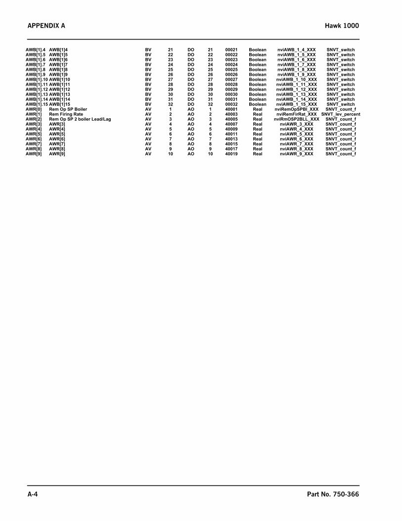
APPENDIX A Hawk 1000
AWB[1].4 AWB[1]4 BV 21 DO 21 00021 Boolean nviAWB_1_4_XXX SNVT_switchAWB[1].5 AWB[1]5 BV 22 DO 22 00022 Boolean nviAWB_1_5_XXX SNVT_switchAWB[1].6 AWB[1]6 BV 23 DO 23 00023 Boolean nviAWB_1_6_XXX SNVT_switchAWB[1].7 AWB[1]7 BV 24 DO 24 00024 Boolean nviAWB_1_7_XXX SNVT_switchAWB[1].8 AWB[1]8 BV 25 DO 25 00025 Boolean nviAWB_1_8_XXX SNVT_switchAWB[1].9 AWB[1]9 BV 26 DO 26 00026 Boolean nviAWB_1_9_XXX SNVT_switchAWB[1].10 AWB[1]10 BV 27 DO 27 00027 Boolean nviAWB_1_10_XXX SNVT_switchAWB[1].11 AWB[1]11 BV 28 DO 28 00028 Boolean nviAWB_1_11_XXX SNVT_switchAWB[1].12 AWB[1]12 BV 29 DO 29 00029 Boolean nviAWB_1_12_XXX SNVT_switchAWB[1].13 AWB[1]13 BV 30 DO 30 00030 Boolean nviAWB_1_13_XXX SNVT_switchAWB[1].14 AWB[1]14 BV 31 DO 31 00031 Boolean nviAWB_1_14_XXX SNVT_switchAWB[1].15 AWB[1]15 BV 32 DO 32 00032 Boolean nviAWB_1_15_XXX SNVT_switchAWR[0] Rem Op SP Boiler AV 1 AO 1 40001 Real nviRemOpSPBl_XXX SNVT_count_fAWR[1] Rem Firing Rate AV 2 AO 2 40003 Real nviRemFirRat_XXX SNVT_lev_percentAWR[2] Rem Op SP 2 boiler Lead/Lag AV 3 AO 3 40005 Real nviRmOSP2BLL_XXX SNVT_count_fAWR[3] AWR[3] AV 4 AO 4 40007 Real nviAWR_3_XXX SNVT_count_fAWR[4] AWR[4] AV 5 AO 5 40009 Real nviAWR_4_XXX SNVT_count_fAWR[5] AWR[5] AV 6 AO 6 40011 Real nviAWR_5_XXX SNVT_count_fAWR[6] AWR[6] AV 7 AO 7 40013 Real nviAWR_6_XXX SNVT_count_fAWR[7] AWR[7] AV 8 AO 8 40015 Real nviAWR_7_XXX SNVT_count_fAWR[8] AWR[8] AV 9 AO 9 40017 Real nviAWR_8_XXX SNVT_count_fAWR[9] AWR[9] AV 10 AO 10 40019 Real nviAWR_9_XXX SNVT_count_f
A-4 Part No. 750-366

Hawk 1000 APPENDIX B
APPENDIX B — LOADING A PLC PROGRAM
Loading a Hawk PLC program from an SD card to an L33ER or L24ER processor.
Required Hardware:
• SD card: Every PLC processor should come with an SD card from Rockwell Automation.
• SD Card Reader
• Laptop Computer
1.If the PLC program file is in .zip format it must beextracted.
2.Use your computer SD card reader or connect an externalSD card reader to the computer.
3.Select the Logix .zip file and right mouse click.
4.Select Open with WinZip (or another extraction program)
5.From WinZip select Extract.
6.Navigate to the location of the SD card that will be used to transfer the Logix folder to the PLC. SelectExtract.
Part No. 750-366 B-1

APPENDIX B Hawk 1000
7.Close the WinZip program.
8.The Logix folder should now be extracted to the SD card. The logix folder must be at the root directory ofthe SD card. No other files should be present on the SD card. Use Windows Explorer to verify the Logix folderon the SD card.
9.Use the Remove Hardware tool to safely eject the SD card from the computer.
B-2 Part No. 750-366

Hawk 1000 APPENDIX B
10. Install the SD card into the PLC SD card slot. The PLC switch should be in REM.
11.Cycle power to the PLC.
12.The transfer from the SD card to the PLC processor will begin. Please bepatient while the installation is in progress, the whole process from power upto completion may take up to 3 Minutes. Prematurely ending the SD card loadprocess may render the PLC unuseable!
13.During the transfer process the OK Led on the PLC will be solid RED. TheSD Led will begin to flash GREEN indicating that the PLC is reading from theSD card. Upon completion, the RUN and OK Led's should be solid GREEN. Ifrun Led is NOT Solid Green put PLC switch to RUN.
14.Remove the SD card from the PLC SD card slot.
15.If the SD card has come from the factory or if the program was taken fromthe CB Portal, loading from the SD card will install PLC firmware, the PLCprogram, and set the IP address of the PLC to 192.168.1.101.
Part No. 750-366 B-3