Hawk 5000 - Cleaver-Brookscleaverbrooks.com/products-and-solutions/controls...HAWK 5000 750-349 1-1...
88
750-349 08/2014 Hawk 5000 Industrial Watertube Boiler Control Operation, Service, and Parts
Transcript of Hawk 5000 - Cleaver-Brookscleaverbrooks.com/products-and-solutions/controls...HAWK 5000 750-349 1-1...
750-34908/2014
Hawk 5000Industrial Watertube Boiler Control
Operation, Service, and Parts
ii
TO: Owners, Operators and/or Maintenance Personnel
This operating manual presents information that will help to properly operate and care for the equipment. Study its con-tents carefully. The unit will provide good service and continued operation if proper operating and maintenance instruc-tions are followed. No attempt should be made to operate the unit until the principles of operation and all of the components are thoroughly understood.
It is the responsibility of the owner to train and advise not only his or her personnel, but the contractors' personnel who are servicing, repairing, or operating the equipment, in all safety aspects.
Cleaver-Brooks equipment is designed and engineered to give long life and excellent service on the job. The electrical and mechanical devices supplied as part of the unit were chosen because of their known ability to perform; however, proper operating techniques and maintenance procedures must be followed at all times.
Any "automatic" features included in the design do not relieve the attendant of any responsibility. Such features merely free him of certain repetitive chores and give him more time to devote to the proper upkeep of equipment.
It is solely the operator’s responsibility to properly operate and maintain the equipment. No amount of written instruc-tions can replace intelligent thinking and reasoning and this manual is not intended to relieve the operating personnel of the responsibility for proper operation. On the other hand, a thorough understanding of this manual is required before attempting to operate, maintain, service, or repair this equipment.
Operating controls will normally function for long periods of time and we have found that some operators become lax in their daily or monthly testing, assuming that normal operation will continue indefinitely. Malfunctions of controls lead to uneconomical operation and damage and, in most cases, these conditions can be traced directly to carelessness and deficiencies in testing and maintenance.
The operation of this equipment by the owner and his operating personnel must comply with all requirements or regula-tions of his insurance company and/or other authority having jurisdiction. In the event of any conflict or inconsistency between such requirements and the warnings or instructions contained herein, please contact Cleaver-Brooks before pro-ceeding.
iii
Cleaver-BrooksHAWK 5000
Industrial Watertube Boiler Control
Operation, Service, and Parts
Manual Part No. 750-34908/2014
Please direct purchase orders for replacement manuals to your local Cleaver-Brooks authorized representative

iv
HAWK 5000Industrial Water-Tube Boiler Controls
Operation, Service & Parts Manual
CONTENTS
1. System Overview . . . . . . . . . . . . . . . . . . . . . . . . . . . . . . . . . . . . . 1-1Introduction . . . . . . . . . . . . . . . . . . . . . . . . . . . . . . . . . . . . . . . . 1-1System Description . . . . . . . . . . . . . . . . . . . . . . . . . . . . . . . . . . . 1-1
2. Specifications. . . . . . . . . . . . . . . . . . . . . . . . . . . . . . . . . . . . . . . . 2-1
3. System Components . . . . . . . . . . . . . . . . . . . . . . . . . . . . . . . . . . . 3-1PLC Hardware Components. . . . . . . . . . . . . . . . . . . . . . . . . . . . . . 3-1Burner Management Control Hardware Components. . . . . . . . . . . . . 3-2Panel-Door Components . . . . . . . . . . . . . . . . . . . . . . . . . . . . . . . . 3-2Sensors. . . . . . . . . . . . . . . . . . . . . . . . . . . . . . . . . . . . . . . . . . . . 3-3
4. Initial System Checkout. . . . . . . . . . . . . . . . . . . . . . . . . . . . . . . . . 4-1Pre-power Up Checks . . . . . . . . . . . . . . . . . . . . . . . . . . . . . . . . . . 4-1Post-Power Up Checks . . . . . . . . . . . . . . . . . . . . . . . . . . . . . . . . . 4-1
5. System Configuration . . . . . . . . . . . . . . . . . . . . . . . . . . . . . . . . . . 5-1Security Login/ Logout . . . . . . . . . . . . . . . . . . . . . . . . . . . . . . . . . 5-1System Configuration Displays . . . . . . . . . . . . . . . . . . . . . . . . . . . . 5-3Changing the PLC and PV+ Ethernet Address . . . . . . . . . . . . . . . . 5-11PLC Process Variable Input Definition . . . . . . . . . . . . . . . . . . . . . . 5-13
6. Fuel Commissioning Process . . . . . . . . . . . . . . . . . . . . . . . . . . . . . 6-1Introduction. . . . . . . . . . . . . . . . . . . . . . . . . . . . . . . . . . . . . . . . . 6-1Calibrating Actuators . . . . . . . . . . . . . . . . . . . . . . . . . . . . . . . . . . 6-1Set Combustion . . . . . . . . . . . . . . . . . . . . . . . . . . . . . . . . . . . . . . 6-4Tune Controls . . . . . . . . . . . . . . . . . . . . . . . . . . . . . . . . . . . . . . 6-11
7. Operating the Boiler from the Human Machine Interface . . . . . . . . . . 7-1Introduction. . . . . . . . . . . . . . . . . . . . . . . . . . . . . . . . . . . . . . . . . 7-1Monitoring the Burner Management Control . . . . . . . . . . . . . . . . . . 7-1Monitoring the Boiler . . . . . . . . . . . . . . . . . . . . . . . . . . . . . . . . . . 7-2Control of Operating Set Points . . . . . . . . . . . . . . . . . . . . . . . . . . . 7-3Alarm Management . . . . . . . . . . . . . . . . . . . . . . . . . . . . . . . . . . . 7-5Monitor PLC I/O . . . . . . . . . . . . . . . . . . . . . . . . . . . . . . . . . . . . . . 7-6Set Limits . . . . . . . . . . . . . . . . . . . . . . . . . . . . . . . . . . . . . . . . . . 7-8Auto-Recycle . . . . . . . . . . . . . . . . . . . . . . . . . . . . . . . . . . . . . . . . 7-9Thermal Shock Protection . . . . . . . . . . . . . . . . . . . . . . . . . . . . . . . 7-9Flow Totalization . . . . . . . . . . . . . . . . . . . . . . . . . . . . . . . . . . . . 7-10
8. Troubleshooting . . . . . . . . . . . . . . . . . . . . . . . . . . . . . . . . . . . . . . 8-1Processor (PLC) . . . . . . . . . . . . . . . . . . . . . . . . . . . . . . . . . . . . . . 8-1Analog I/O Modules . . . . . . . . . . . . . . . . . . . . . . . . . . . . . . . . . . . 8-2Digital I/O Modules . . . . . . . . . . . . . . . . . . . . . . . . . . . . . . . . . . . 8-3
v
Power Supply . . . . . . . . . . . . . . . . . . . . . . . . . . . . . . . . . . . . . . . 8-3PanelView Plus . . . . . . . . . . . . . . . . . . . . . . . . . . . . . . . . . . . . . . 8-3PLC Battery Replacement . . . . . . . . . . . . . . . . . . . . . . . . . . . . . . 8-3Boiler will not start (Recycle Limit Relay) . . . . . . . . . . . . . . . . . 8-5Boiler will not start (Non-Recycle Limit Relay) . . . . . . . . . . . . . 8-5Analog Input Channel Bad Quality . . . . . . . . . . . . . . . . . . . . . . . 8-5
AppendicesA. PowerFlex 400 Drive Parameters
B. Procedure To Load Program And Set Up PanelView PlusC. Procedure To Set Actuator StrokeD. Boiler START/ STOP Sequence
E. Hawk 5000 I/O ListF. Hawk 5000 Alarm List
G. Parts
vi
HAWK 5000
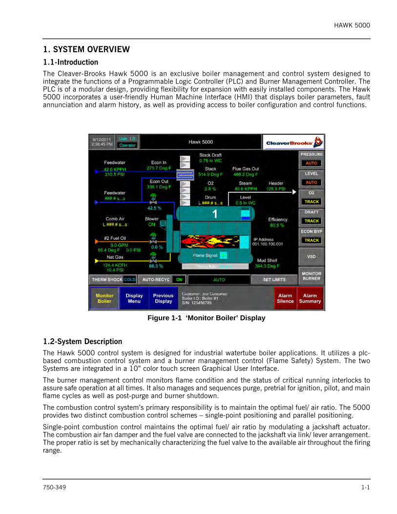
1. SYSTEM OVERVIEW1.1-IntroductionThe Cleaver-Brooks Hawk 5000 is an exclusive boiler management and control system designed tointegrate the functions of a Programmable Logic Controller (PLC) and Burner Management Controller. ThePLC is of a modular design, providing flexibility for expansion with easily installed components. The Hawk5000 incorporates a user-friendly Human Machine Interface (HMI) that displays boiler parameters, faultannunciation and alarm history, as well as providing access to boiler configuration and control functions.
Figure 1-1 ‘Monitor Boiler’ Display
1.2-System DescriptionThe Hawk 5000 control system is designed for industrial watertube boiler applications. It utilizes a plc-based combustion control system and a burner management control (Flame Safety) System. The twoSystems are integrated in a 10” color touch screen Graphical User Interface.
The burner management control monitors flame condition and the status of critical running interlocks toassure safe operation at all times. It also manages and sequences purge, pretrial for ignition, pilot, and mainflame cycles as well as post-purge and burner shutdown.
The combustion control system’s primary responsibility is to maintain the optimal fuel/ air ratio. The 5000provides two distinct combustion control schemes – single-point positioning and parallel positioning.
Single-point combustion control maintains the optimal fuel/ air ratio by modulating a jackshaft actuator.The combustion air fan damper and the fuel valve are connected to the jackshaft via link/ lever arrangement.The proper ratio is set by mechanically characterizing the fuel valve to the available air throughout the firingrange.
750-349 1-1
HAWK 5000
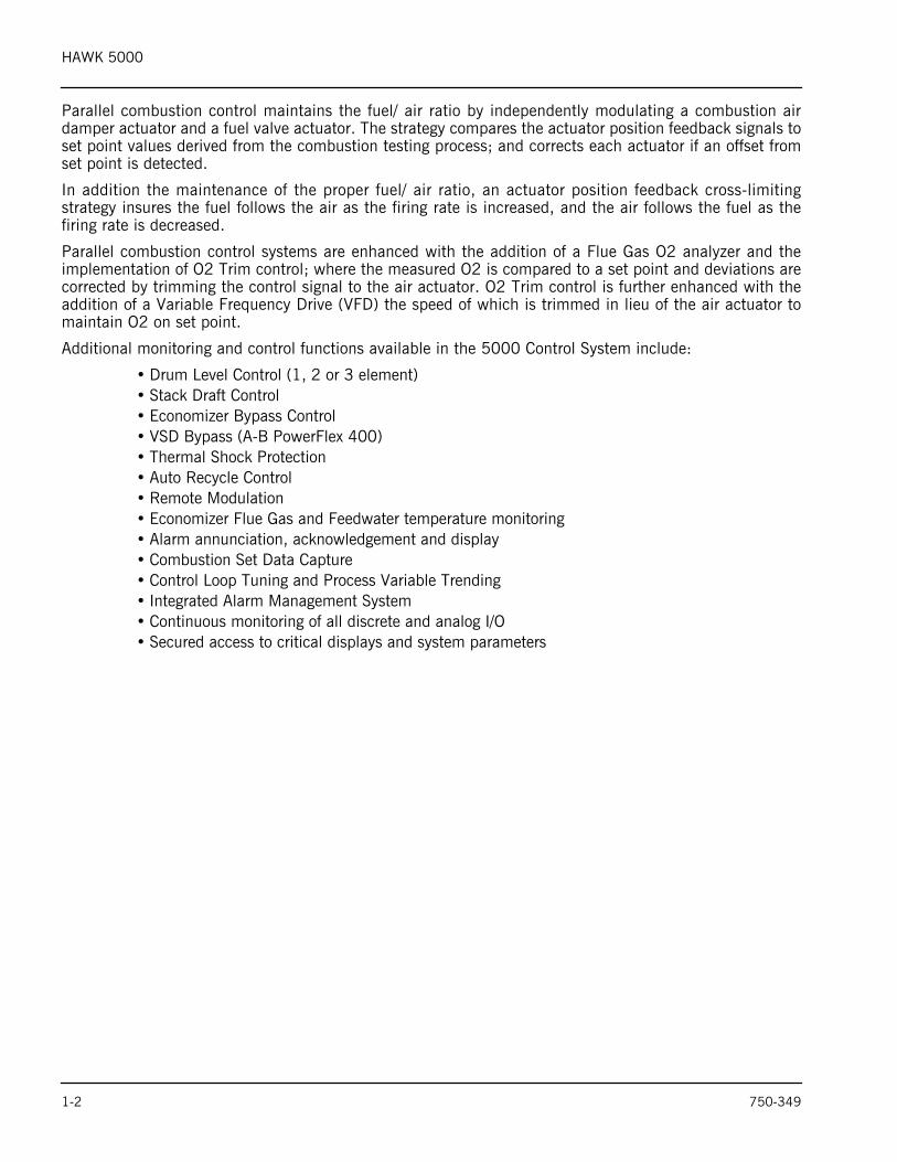
Parallel combustion control maintains the fuel/ air ratio by independently modulating a combustion airdamper actuator and a fuel valve actuator. The strategy compares the actuator position feedback signals toset point values derived from the combustion testing process; and corrects each actuator if an offset fromset point is detected.
In addition the maintenance of the proper fuel/ air ratio, an actuator position feedback cross-limitingstrategy insures the fuel follows the air as the firing rate is increased, and the air follows the fuel as thefiring rate is decreased.
Parallel combustion control systems are enhanced with the addition of a Flue Gas O2 analyzer and theimplementation of O2 Trim control; where the measured O2 is compared to a set point and deviations arecorrected by trimming the control signal to the air actuator. O2 Trim control is further enhanced with theaddition of a Variable Frequency Drive (VFD) the speed of which is trimmed in lieu of the air actuator tomaintain O2 on set point.
Additional monitoring and control functions available in the 5000 Control System include:
• Drum Level Control (1, 2 or 3 element)• Stack Draft Control• Economizer Bypass Control• VSD Bypass (A-B PowerFlex 400)• Thermal Shock Protection• Auto Recycle Control• Remote Modulation• Economizer Flue Gas and Feedwater temperature monitoring• Alarm annunciation, acknowledgement and display• Combustion Set Data Capture • Control Loop Tuning and Process Variable Trending• Integrated Alarm Management System• Continuous monitoring of all discrete and analog I/O• Secured access to critical displays and system parameters
1-2 750-349
HAWK 5000
750-349 2-1
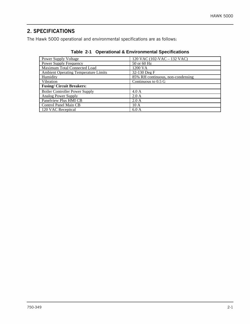
2. SPECIFICATIONSThe Hawk 5000 operational and environmental specifications are as follows:
Table 2-1 Operational & Environmental SpecificationsPower Supply Voltage 120 VAC (102-VAC – 132 VAC)Power Supply Frequency 50 or 60 HzMaximum Total Connected Load 1200 VAAmbient Operating Temperature Limits 32-130 Deg FHumidity 85% RH continuous, non-condensingVibration Continuous to 0.5 GFusing/ Circuit Breakers:Boiler Controller Power Supply 4.0 AAnalog Power Supply 2.0 APanelview Plus HMI CB 2.0 AControl Panel Main CB 10 A120 VAC Recepitcal 6.0 A

HAWK 5000
2-2 750-349
HAWK 5000
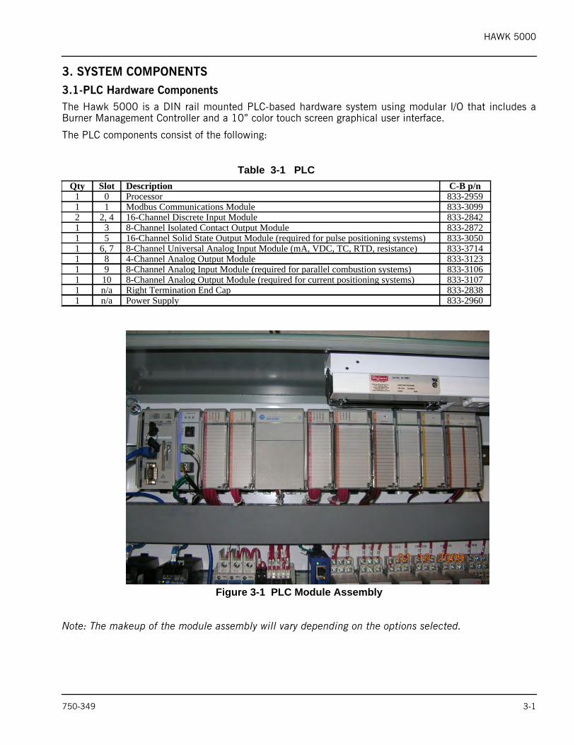
3. SYSTEM COMPONENTS3.1-PLC Hardware ComponentsThe Hawk 5000 is a DIN rail mounted PLC-based hardware system using modular I/O that includes aBurner Management Controller and a 10” color touch screen graphical user interface.
The PLC components consist of the following:
Figure 3-1 PLC Module Assembly
Note: The makeup of the module assembly will vary depending on the options selected.
Table 3-1 PLCQty Slot Description C-B p/n
1 0 Processor 833-29591 1 Modbus Communications Module 833-30992 2, 4 16-Channel Discrete Input Module 833-28421 3 8-Channel Isolated Contact Output Module 833-28721 5 16-Channel Solid State Output Module (required for pulse positioning systems) 833-30501 6, 7 8-Channel Universal Analog Input Module (mA, VDC, TC, RTD, resistance) 833-37141 8 4-Channel Analog Output Module 833-31231 9 8-Channel Analog Input Module (required for parallel combustion systems) 833-31061 10 8-Channel Analog Output Module (required for current positioning systems) 833-31071 n/a Right Termination End Cap 833-28381 n/a Power Supply 833-2960
750-349 3-1
HAWK 5000
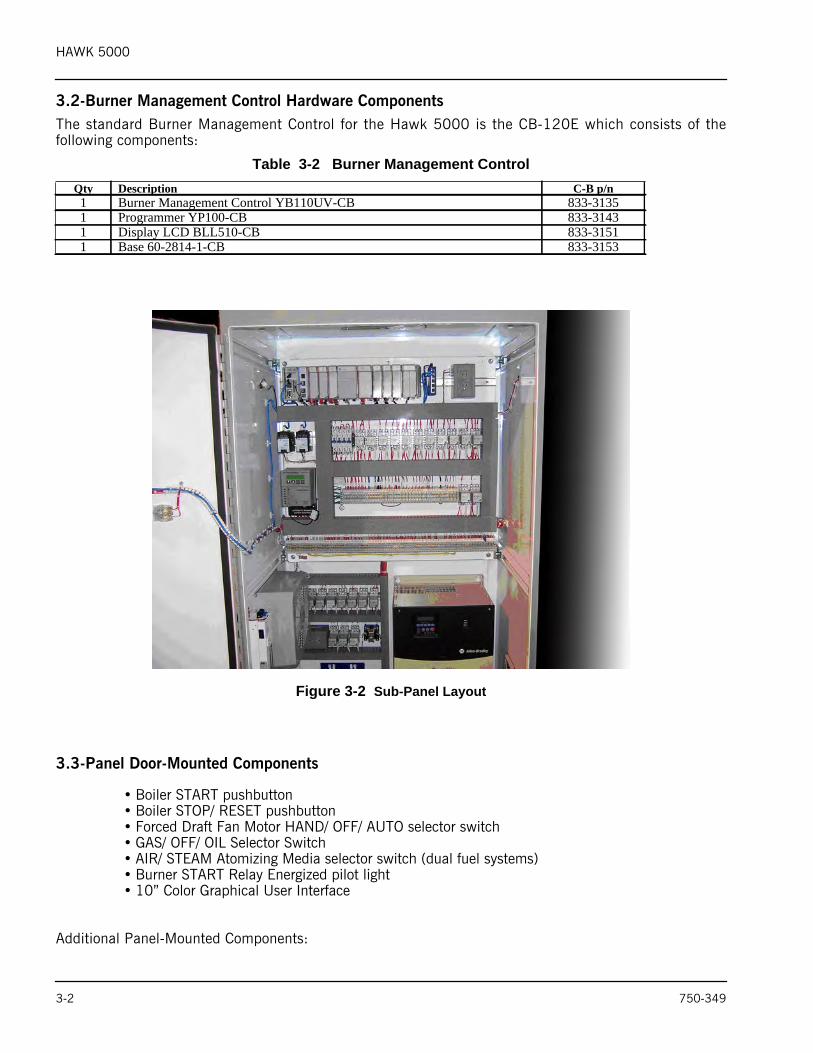
3.2-Burner Management Control Hardware ComponentsThe standard Burner Management Control for the Hawk 5000 is the CB-120E which consists of thefollowing components:
Table 3-2 Burner Management Control
Figure 3-2 Sub-Panel Layout
3.3-Panel Door-Mounted Components
• Boiler START pushbutton• Boiler STOP/ RESET pushbutton• Forced Draft Fan Motor HAND/ OFF/ AUTO selector switch• GAS/ OFF/ OIL Selector Switch• AIR/ STEAM Atomizing Media selector switch (dual fuel systems)• Burner START Relay Energized pilot light• 10” Color Graphical User Interface
Additional Panel-Mounted Components:
Qty Description C-B p/n1 Burner Management Control YB110UV-CB 833-31351 Programmer YP100-CB 833-31431 Display LCD BLL510-CB 833-31511 Base 60-2814-1-CB 833-3153
3-2 750-349
HAWK 5000
Table 3-3
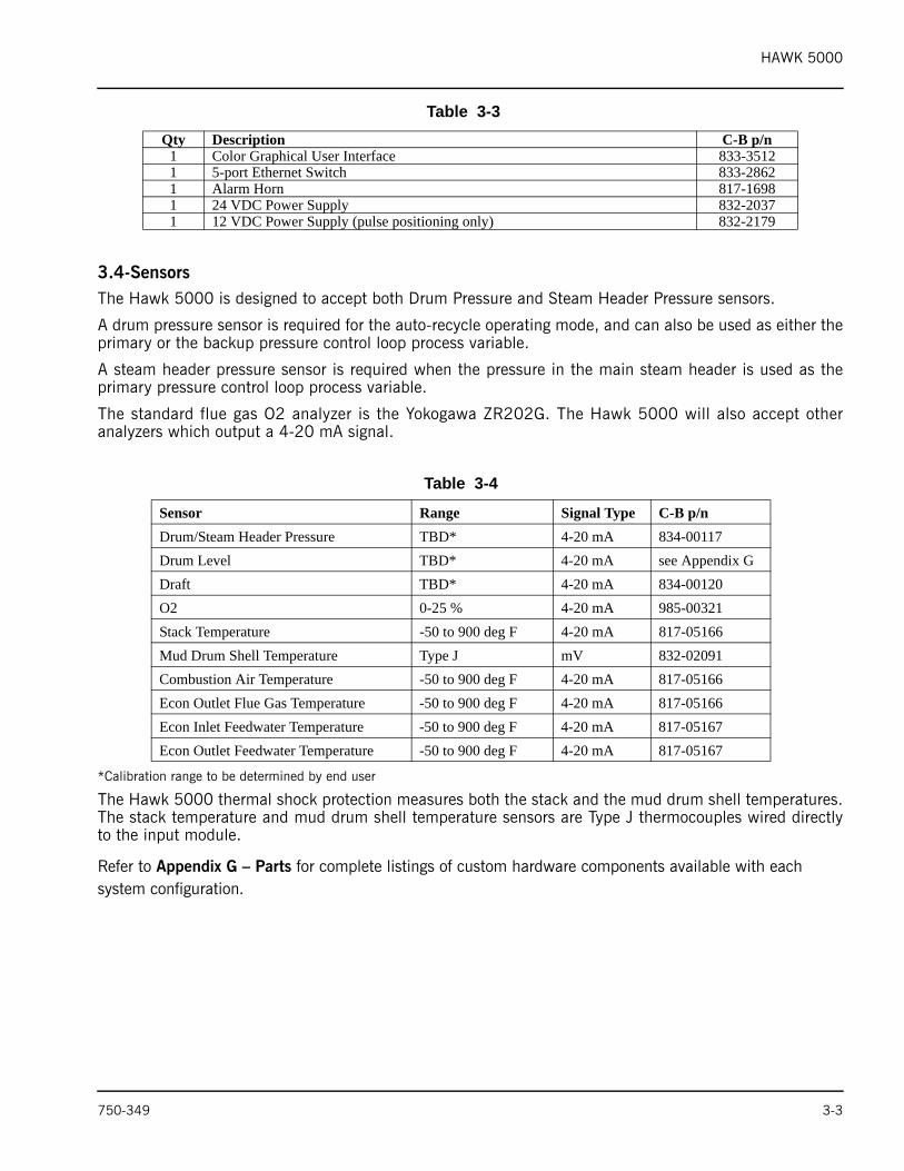
3.4-SensorsThe Hawk 5000 is designed to accept both Drum Pressure and Steam Header Pressure sensors.
A drum pressure sensor is required for the auto-recycle operating mode, and can also be used as either theprimary or the backup pressure control loop process variable.
A steam header pressure sensor is required when the pressure in the main steam header is used as theprimary pressure control loop process variable.
The standard flue gas O2 analyzer is the Yokogawa ZR202G. The Hawk 5000 will also accept otheranalyzers which output a 4-20 mA signal.
*Calibration range to be determined by end user
The Hawk 5000 thermal shock protection measures both the stack and the mud drum shell temperatures.The stack temperature and mud drum shell temperature sensors are Type J thermocouples wired directlyto the input module.
Refer to Appendix G – Parts for complete listings of custom hardware components available with each system configuration.
Qty Description C-B p/n1 Color Graphical User Interface 833-35121 5-port Ethernet Switch 833-28621 Alarm Horn 817-16981 24 VDC Power Supply 832-20371 12 VDC Power Supply (pulse positioning only) 832-2179
Table 3-4
Sensor Range Signal Type C-B p/nDrum/Steam Header Pressure TBD* 4-20 mA 834-00117Drum Level TBD* 4-20 mA see Appendix GDraft TBD* 4-20 mA 834-00120O2 0-25 % 4-20 mA 985-00321Stack Temperature -50 to 900 deg F 4-20 mA 817-05166Mud Drum Shell Temperature Type J mV 832-02091Combustion Air Temperature -50 to 900 deg F 4-20 mA 817-05166Econ Outlet Flue Gas Temperature -50 to 900 deg F 4-20 mA 817-05166Econ Inlet Feedwater Temperature -50 to 900 deg F 4-20 mA 817-05167Econ Outlet Feedwater Temperature -50 to 900 deg F 4-20 mA 817-05167
750-349 3-3

HAWK 5000
3-4 750-349
HAWK 5000
4. INITIAL SYSTEM CHECKOUT4.1-Pre-Power-Up ChecksPrior to commissioning the Hawk 5000 Control System it is necessary to confirm that all of the integralcomponents and interconnecting wiring are in place and secure. Vibration and jarring from transport orinstallation may have loosened components or wiring terminals. It is good practice to check all systemcomponents for integrity and tightness prior to the initial power-up of the system.
All external interlocks, control devices, and process instrumentation should first be checked for properinstallation and wired properly into the system.
Remove any packing material and shipping fasteners.
Check that all I/O module DIN rail latches, and all module bus locking levers are properly engaged.
Verify modbus communication cables are properly connected to the SM2 modbus communications module,and to the Flame Safeguard and VSD (optional).
Verify the PLC and PanelView Plus GUI are both connected via Cat5 Ethernet cable to the Ethernet switch.
4.2-Post-power-up ChecksVerify Flame Safeguard modbus address is set to 5 and the baud rate to 4800. Verify the CH3 LED on theSM2 Modbus Communications Module (CH1 if CB780E) is flashing – indicating communication isestablished to the PLC.
In systems equipped with a Power-Flex 400 VSD, verify the drives’ modbus address is set to 4 and the baudrate to 9600. Verify the CH2 LED on the SM2 Modbus Communications Module is flashing – indicatingcommunication is established to the PLC. Set all applicable drive parameters.
Verify PLC key-switch is in the RUN position and the RUN, I/O and OK LED’s are solid green.
Verify the OK LED’s on all analog I/O modules are solid green, and the green power LED on the PA4 powersupply lit.
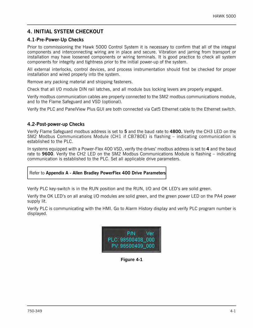
Verify PLC is communicating with the HMI. Go to Alarm History display and verify PLC program number isdisplayed.
Figure 4-1
Refer to Appendix A - Allen Bradley PowerFlex 400 Drive Parameters
750-349 4-1

HAWK 5000
4-2 750-349
HAWK 5000
5. SYSTEM CONFIGURATION5.1-Security Login/ LogoutThe Graphical User Interface utilizes a four tier security system. Each tier is identified by a User I.D.; eachUser I.D. has a unique 4 digit numeric password.
1.Blank (no user currently logged in)2.Operator3.Service4.CB
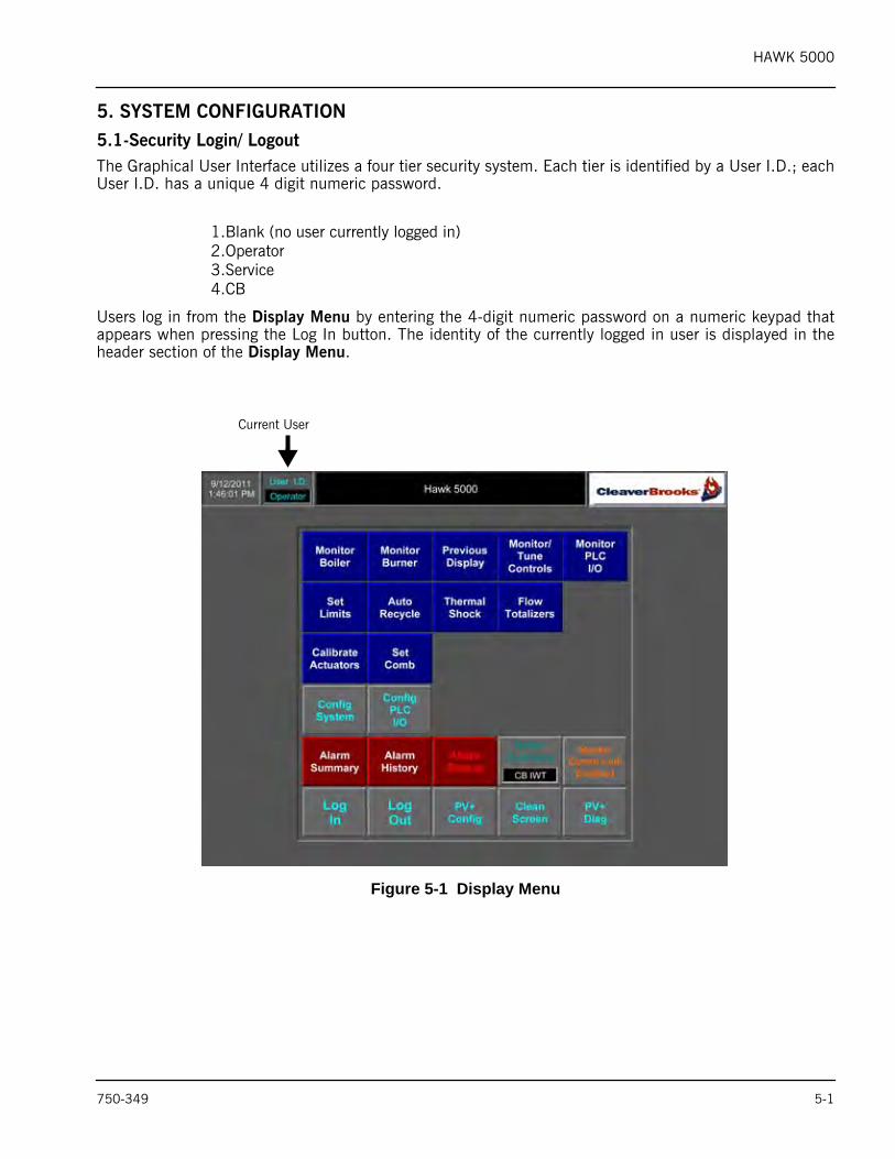
Users log in from the Display Menu by entering the 4-digit numeric password on a numeric keypad thatappears when pressing the Log In button. The identity of the currently logged in user is displayed in theheader section of the Display Menu.
Figure 5-1 Display Menu
Current User
750-349 5-1
HAWK 5000
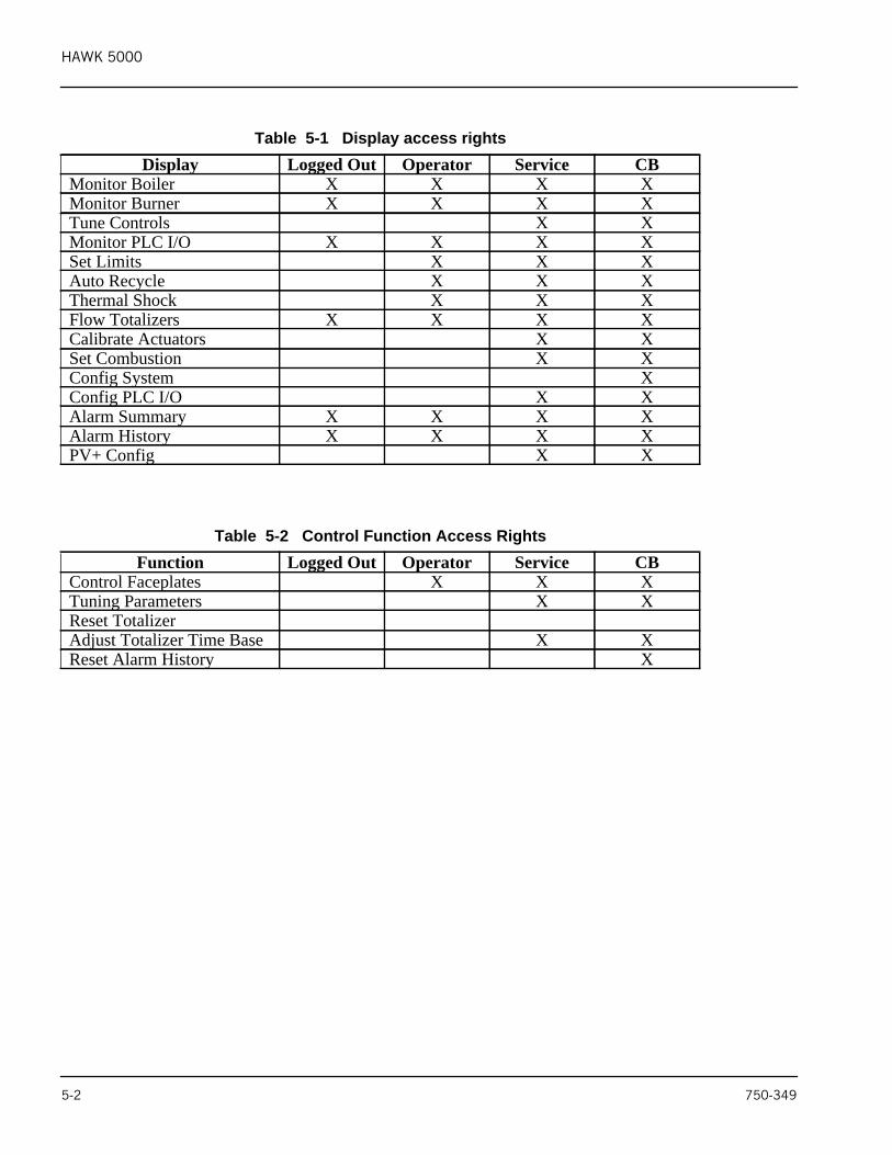
Table 5-1 Display access rightsDisplay Logged Out Operator Service CB
Monitor Boiler X X X XMonitor Burner X X X XTune Controls X XMonitor PLC I/O X X X XSet Limits X X XAuto Recycle X X XThermal Shock X X XFlow Totalizers X X X XCalibrate Actuators X XSet Combustion X XConfig System XConfig PLC I/O X XAlarm Summary X X X XAlarm History X X X XPV+ Config X X
Table 5-2 Control Function Access RightsFunction Logged Out Operator Service CB
Control Faceplates X X XTuning Parameters X XReset TotalizerAdjust Totalizer Time Base X XReset Alarm History X
5-2 750-349

HAWK 5000
5.2-System Configuration Displays
This section describes the general functionality of the user-selectable options presented on the SystemConfiguration displays and identifies the process inputs each option requires.
Refer to Section 7 - Operating the Boiler from the Graphical User Interface - for more detailed descriptionsof the options’ control functionality.
Access to the Config System button requires logging in with the User I.D. of “CB”. Upon successful log in,the following messages are displayed. Please read all screen messages carefully before proceeding.
Figure 5-2 Warning Message
After reading the warning messages proceed to the System Config 1 display by pressing System Config.
For options requiring a specific I/O module, check that the module is indeed present and located in itsproper slot BEFORE selecting that option.
Failure to do so will fault the processor if the module is not present and require the PLC program to bereloaded.
To System Config 1 screen
750-349 5-3
HAWK 5000
System Configuration 1
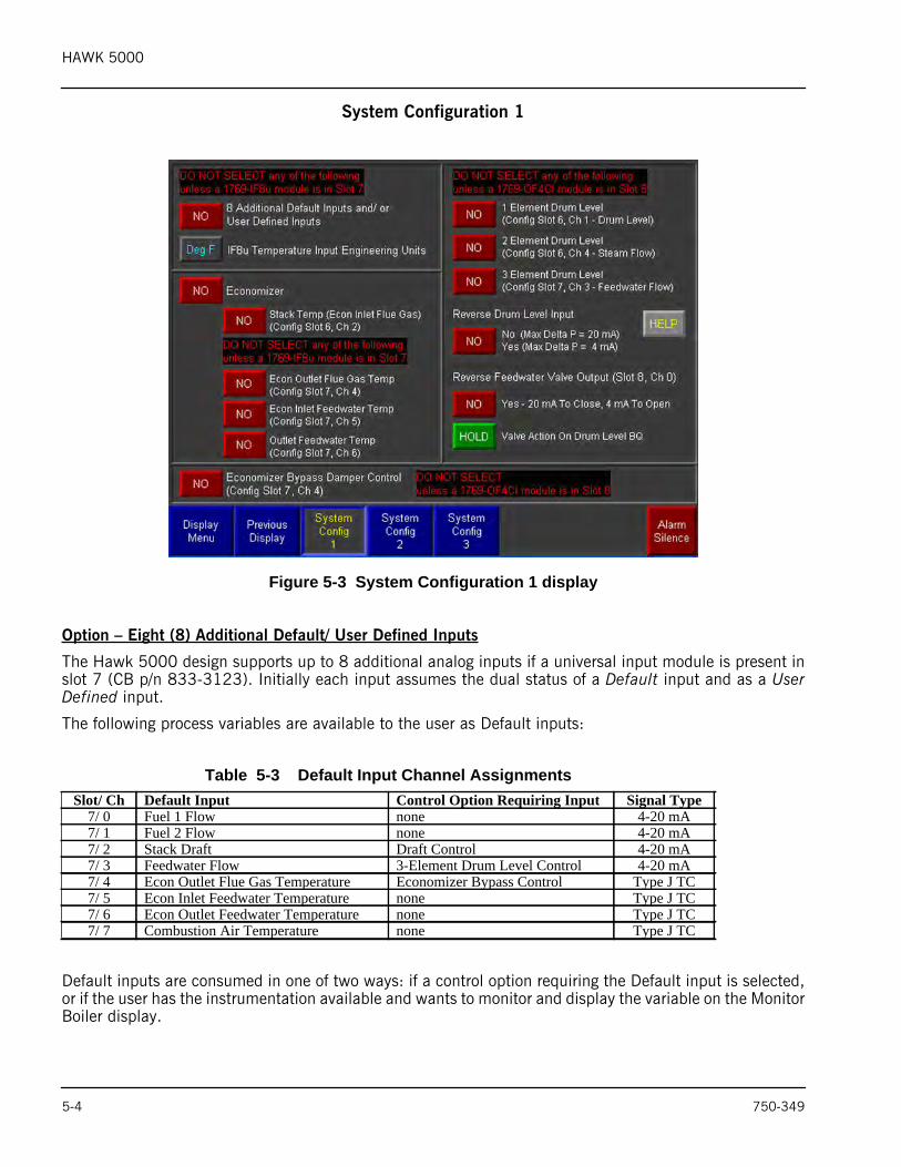
Figure 5-3 System Configuration 1 display
Option – Eight (8) Additional Default/ User Defined Inputs
The Hawk 5000 design supports up to 8 additional analog inputs if a universal input module is present inslot 7 (CB p/n 833-3123). Initially each input assumes the dual status of a Default input and as a UserDefined input.
The following process variables are available to the user as Default inputs:
Default inputs are consumed in one of two ways: if a control option requiring the Default input is selected,or if the user has the instrumentation available and wants to monitor and display the variable on the MonitorBoiler display.
Table 5-3 Default Input Channel AssignmentsSlot/ Ch Default Input Control Option Requiring Input Signal Type
7/ 0 Fuel 1 Flow none 4-20 mA7/ 1 Fuel 2 Flow none 4-20 mA7/ 2 Stack Draft Draft Control 4-20 mA7/ 3 Feedwater Flow 3-Element Drum Level Control 4-20 mA7/ 4 Econ Outlet Flue Gas Temperature Economizer Bypass Control Type J TC7/ 5 Econ Inlet Feedwater Temperature none Type J TC7/ 6 Econ Outlet Feedwater Temperature none Type J TC7/ 7 Combustion Air Temperature none Type J TC
5-4 750-349
HAWK 5000
For example Default input Feedwater Flow is automatically consumed when selecting the 3-Element DrumLevel Control option. The Default input Fuel 1 Flow would be consumed if the user wanted to wire a newor existing Fuel 1 Flow transmitter into the system.
As Default inputs are consumed the number of User Defined inputs available decreases. For a detaileddescription on how to configure a User Defined input refer to Section 5.4 – PLC Process Variable InputDefinition.
All Default inputs are automatically displayed on the Monitor Boiler display (Figure 1-1).
Option – Economizer
When selecting the Economizer option a graphical symbol of an economizer appears in the outlet ductsection of the Monitor Boiler display. The user can also select for display the instrumentation measuringinlet and outlet flue gas and feedwater temperatures.
Option – Economizer Bypass Damper Control
As illustrated in Table 5-3, selecting Economizer Bypass Damper Control consumes the Default input EconOutlet Flue Gas Temperature. The input is compared to an adjustable set point value, and if the input isless than set point the damper is modulated closed. If the input is greater than set point the damper ismodulated full open.
Before selecting the Economizer Bypass Damper Control option, verify a 4-channel analog output moduleis present in Slot 8 (CB p/n 833-3123). The bypass damper is wired to field terminals connected to slot 8,channel 2.
Note that Economizer Bypass Damper Control is not available in systems utilizing single-point combustioncontrol.
Option – Drum Level Control
There are three (3) Drum Level Control options: 1-Element, 2-Element, and 3-Element.
1-Element consumes the fixed input Drum Level which is permanently assigned to slot 6, channel 1. Alongwith fixed input Drum Level, 2-Element consumes the fixed input Steam Flow which is permanentlyassigned to slot 6, channel 5. Along with the fixed inputs Drum Level and Steam Flow, 3-Element consumesthe Default input Feedwater Flow which is assigned to slot 7, channel 4.
Before selecting a Drum Level Control option, verify a 4-channel analog output module is present in slot 8(CB p/n 833-3123). The Feedwater FCV is wired to field terminals connected to slot 8, channel 0.
The Drum Level section includes the following additional selections:
• Reverse the Drum Level input signal (press the Help button for details).• Reverse the control output signal to the Feedwater FCV.• Specify the Feedwater FCV action if the Drum Level input is out of range.
750-349 5-5
HAWK 5000
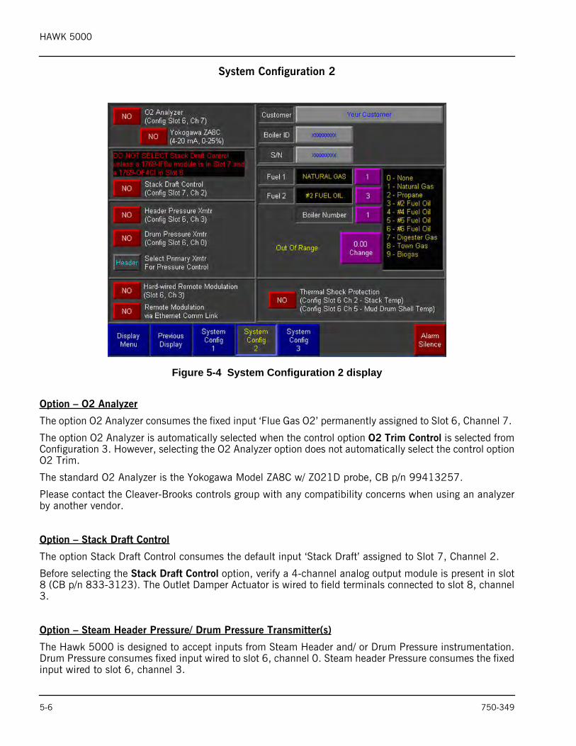
System Configuration 2
Figure 5-4 System Configuration 2 display
Option – O2 Analyzer
The option O2 Analyzer consumes the fixed input ‘Flue Gas O2’ permanently assigned to Slot 6, Channel 7.
The option O2 Analyzer is automatically selected when the control option O2 Trim Control is selected fromConfiguration 3. However, selecting the O2 Analyzer option does not automatically select the control optionO2 Trim.
The standard O2 Analyzer is the Yokogawa Model ZA8C w/ Z021D probe, CB p/n 99413257.
Please contact the Cleaver-Brooks controls group with any compatibility concerns when using an analyzerby another vendor.
Option – Stack Draft Control
The option Stack Draft Control consumes the default input ‘Stack Draft’ assigned to Slot 7, Channel 2.
Before selecting the Stack Draft Control option, verify a 4-channel analog output module is present in slot8 (CB p/n 833-3123). The Outlet Damper Actuator is wired to field terminals connected to slot 8, channel3.
Option – Steam Header Pressure/ Drum Pressure Transmitter(s)
The Hawk 5000 is designed to accept inputs from Steam Header and/ or Drum Pressure instrumentation.Drum Pressure consumes fixed input wired to slot 6, channel 0. Steam header Pressure consumes the fixedinput wired to slot 6, channel 3.
5-6 750-349
HAWK 5000
The Drum Pressure input is required for the Auto-Recycle Control function and can also be used to controlSteam Pressure in the following scenarios:
a) System without a Steam Header Pressure instrument.b) System with a Steam Header Pressure instrument as the primary and Drum Pressure as the backup.
A Steam Header Pressure sensor cannot be used in systems with a hard-wired Remote Modulation input.
Scenario (b) requires the user to select a primary instrument with a control included in the group and shownbelow.
Option – Remote Modulation
The Hawk 5000 is designed to accept a remote modulation input from a plant master; two user selectablemethods are available to receive the input:
a) Hard-wired 4-20 mA input signalb) Ethernet Communication Link
Option (b) is required when using the Hawk Master Panel.
Selecting option (a) will consume fixed input Remote Modulation, wired to Slot 6, Channel 3.
Option (a) cannot be selected in systems using a Steam Header Pressure instrument.
Option – Thermal Shock Protection
The Hawk 5000 Thermal Shock Protection scheme considers both stack temperature and mud drum shelltemperature in its calculations to determine if a boiler is warm enough to take up a load. Both inputs arerequired for thermal shock protection.
Thermal Shock Protection consumes two fixed inputs: Stack Temperature (wired to Slot 6, Channel 2) andMud Drum Shell Temperature (wired to Slot 6, Channel 6).
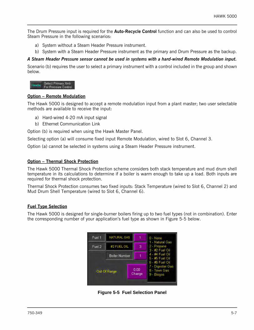
Fuel Type Selection
The Hawk 5000 is designed for single-burner boilers firing up to two fuel types (not in combination). Enterthe corresponding number of your application’s fuel type as shown in Figure 5-5 below.
Figure 5-5 Fuel Selection Panel
750-349 5-7
HAWK 5000
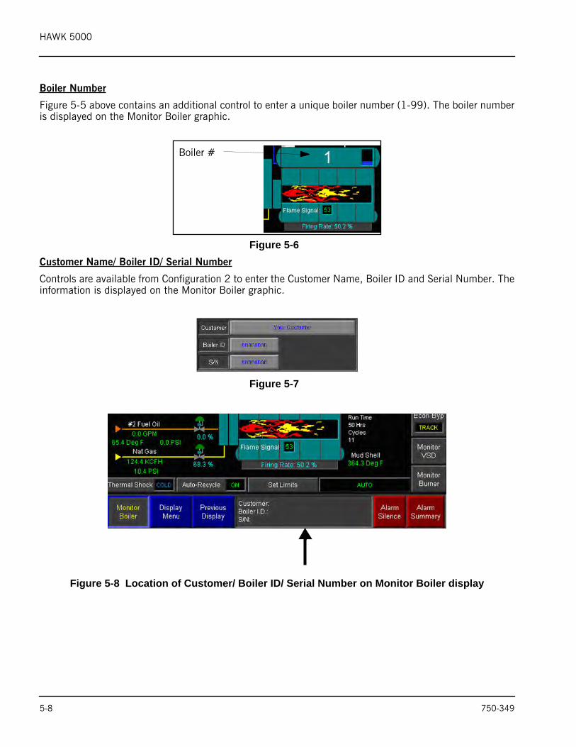
Boiler Number
Figure 5-5 above contains an additional control to enter a unique boiler number (1-99). The boiler numberis displayed on the Monitor Boiler graphic.
Figure 5-6 Customer Name/ Boiler ID/ Serial Number
Controls are available from Configuration 2 to enter the Customer Name, Boiler ID and Serial Number. Theinformation is displayed on the Monitor Boiler graphic.
Figure 5-7
Figure 5-8 Location of Customer/ Boiler ID/ Serial Number on Monitor Boiler display
Boiler #
5-8 750-349
HAWK 5000
System Configuration 3
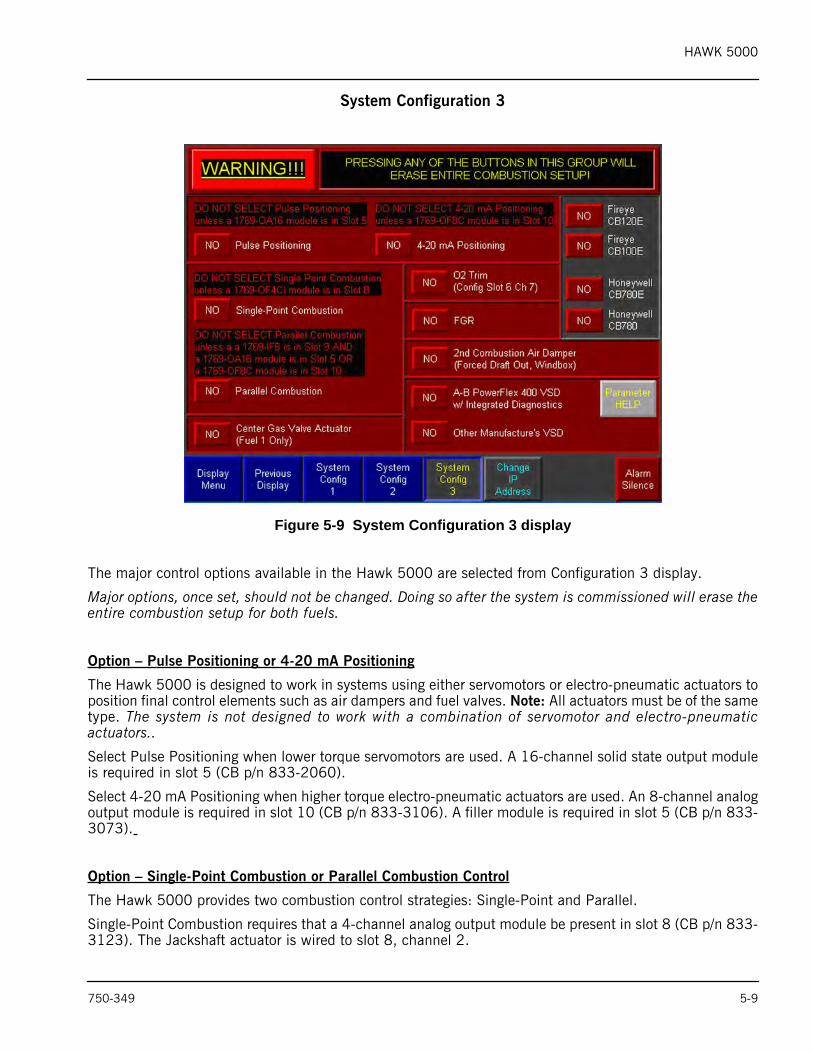
Figure 5-9 System Configuration 3 display
The major control options available in the Hawk 5000 are selected from Configuration 3 display.
Major options, once set, should not be changed. Doing so after the system is commissioned will erase theentire combustion setup for both fuels.
Option – Pulse Positioning or 4-20 mA Positioning
The Hawk 5000 is designed to work in systems using either servomotors or electro-pneumatic actuators toposition final control elements such as air dampers and fuel valves. Note: All actuators must be of the sametype. The system is not designed to work with a combination of servomotor and electro-pneumaticactuators..
Select Pulse Positioning when lower torque servomotors are used. A 16-channel solid state output moduleis required in slot 5 (CB p/n 833-2060).
Select 4-20 mA Positioning when higher torque electro-pneumatic actuators are used. An 8-channel analogoutput module is required in slot 10 (CB p/n 833-3106). A filler module is required in slot 5 (CB p/n 833-3073).
Option – Single-Point Combustion or Parallel Combustion Control
The Hawk 5000 provides two combustion control strategies: Single-Point and Parallel.
Single-Point Combustion requires that a 4-channel analog output module be present in slot 8 (CB p/n 833-3123). The Jackshaft actuator is wired to slot 8, channel 2.
750-349 5-9
HAWK 5000
Note that Single-Point Combustion is not an available option in systems utilizing the Economizer BypassControl option because they share the same output channel.
Parallel Combustion requires that either a 16-channel solid state output module be present in slot 5 (pulsepositioning) or an 8-channel analog output module be present in slot 9 (4-20 mA positioning).
In both pulse and 4-20 mA systems an 8-channel analog input module is required in slot 9 (CB p/n 833-3106). The purpose of the module is to input the actuator position feedback signals into the system. Notealso that the feedback signal wiring method to the module will be different for servos (0-10 VDC) andelectro-pneumatic actuators (4-20 mA).
Option – Center Gas Valve Actuator
The Hawk 5000 is designed to support burner designs that use lance gas and center (core) gas actuators– both servo and electro-pneumatic. Selecting this option activates the PLC logic to characterize and controlthe output to the actuator.
Option – 2nd Combustion Air Damper Actuator
The Hawk 5000 is designed to support burner designs that use a 2nd Combustion Air Damper actuator (FDInlet/Outlet, Windbox). Selecting this option activates the PLC logic to characterize and control the actuator.
Option – 2nd FGR Damper Actuator
The Hawk 5000 is designed to support burner designs that utilize Flue Gas Recirculation (FGR) to controlNOx. Both servo and electro-pneumatic actuators are supported. Selecting this option activates the PLClogic to characterize and control the output to the actuator.
Option – AB PowerFlex VSD or Other Manufacturer’s VSD
The standard VSD is the AB PowerFlex 400 with built-in modbus communication port. The modbus linkallows for the integration of drive diagnostic data and alarms into Hawk 5000 HMI displays designedspecifically to support the drive.
The Hawk 5000 can control VSDs by other manufacturers but the Modbus communications feature isturned off, as are the integrated diagnostics.
All VSDs regardless of manufacture must be able to receive and send the following commands:
• Input a 4-20 mA speed reference signal• Output a 4-20 mA speed feedback signal• Input a dry contact START/ RUN signal
The maximum speed setting for all VSDs regardless of manufacture is 60 Hz.
Selecting the VSD option activates the PLC logic to characterize and control the output to the drive.
Option – O2 Trim Control
The option O2 Trim Control consumes the fixed input Flue Gas O2 permanently assigned to slot 6, channel7. The standard O2 Analyzer is the Yokogawa Model ZA8C w/ Z021D probe, CB p/n 99413257.
O2 Trim Control makes continuous corrections to the position of the combustion air damper to maintain O2on set point. In systems with a VSD continuous corrections are made to the VSD speed reference signal.
5-10 750-349
HAWK 5000
Option – Burner Management Control
The Hawk 5000 supports both the latest and legacy versions of the burner management controls providedby Honeywell and Fireye. Selecting one of the above enables the Modbus communications link between theburner management controller and the Hawk 5000 PLC. The standard burner management control is theCB120E. Refer to Publication 750-264 for details.
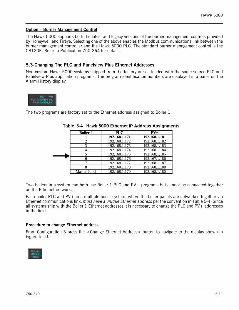
5.3-Changing The PLC and Panelview Plus Ethernet AddressesNon-custom Hawk 5000 systems shipped from the factory are all loaded with the same source PLC andPanelview Plus application programs. The program identification numbers are displayed in a panel on theAlarm History display
The two programs are factory set to the Ethernet address assigned to Boiler 1.
Two boilers in a system can both use Boiler 1 PLC and PV+ programs but cannot be connected togetheron the Ethernet network.
Each boiler PLC and PV+ in a multiple boiler system, where the boiler panels are networked together viaEthernet communications link, must have a unique Ethernet address per the convention in Table 5-4. Sinceall systems ship with the Boiler 1 Ethernet addresses it is necessary to change the PLC and PV+ addressesin the field.
Procedure to change Ethernet address
From Configuration 3 press the <Change Ethernet Address> button to navigate to the display shown inFigure 5-10.
Table 5-4 Hawk 5000 Ethernet IP Address AssignmentsBoiler # PLC PV+
1 192.168.1.171 192.168.1.1812 192.168.1.172 192.168.1.1823 192.168.1.173 192.168.1.1834 192.168.1.174 192.168.1.1845 192.168.1.175 192,168,1,1856 192.168.1.176 192.167.1.1867 192.168.1.177 192.168.1.1878 192.168.1.178 192.168.1.188
Master Panel 192.168.1.170 192.168.1.180
750-349 5-11
HAWK 5000
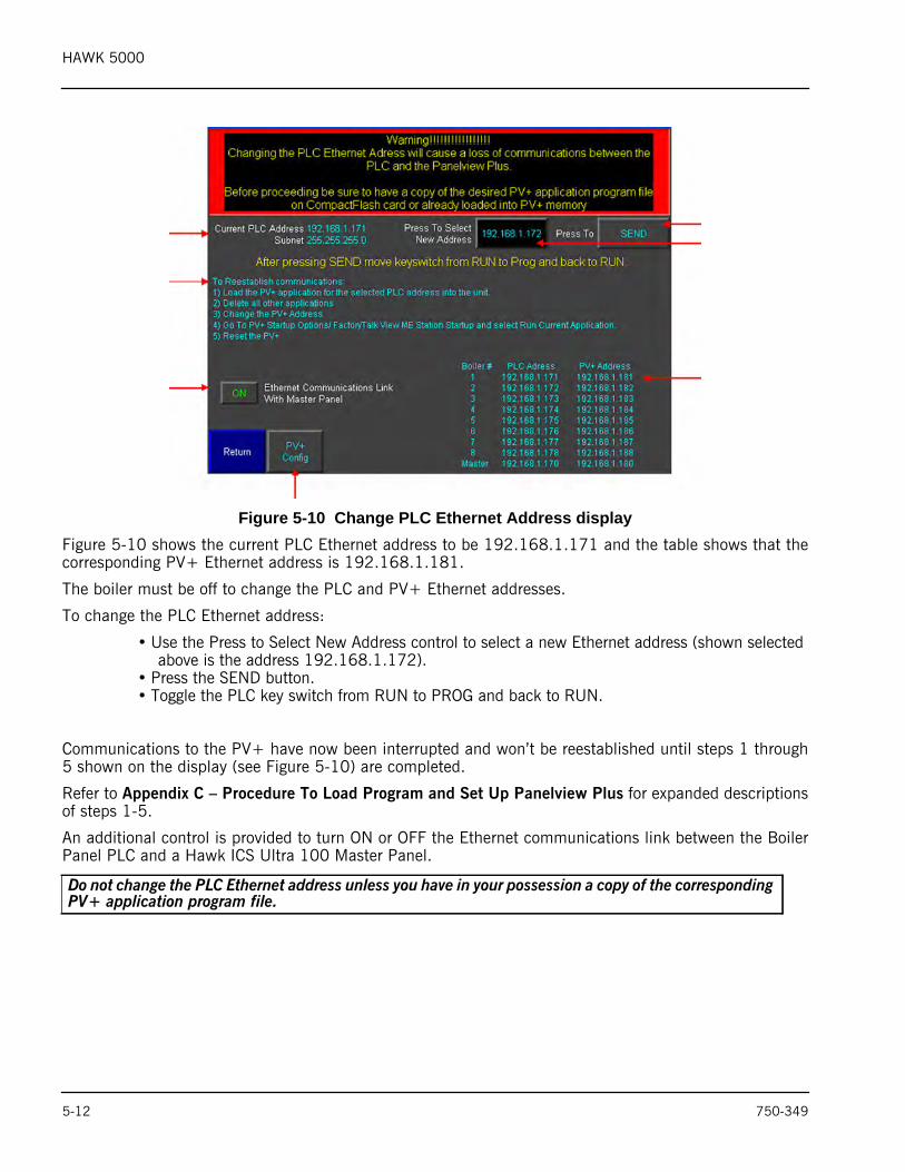
Figure 5-10 Change PLC Ethernet Address displayFigure 5-10 shows the current PLC Ethernet address to be 192.168.1.171 and the table shows that thecorresponding PV+ Ethernet address is 192.168.1.181.
The boiler must be off to change the PLC and PV+ Ethernet addresses.
To change the PLC Ethernet address:
• Use the Press to Select New Address control to select a new Ethernet address (shown selected above is the address 192.168.1.172).
• Press the SEND button.• Toggle the PLC key switch from RUN to PROG and back to RUN.
Communications to the PV+ have now been interrupted and won’t be reestablished until steps 1 through5 shown on the display (see Figure 5-10) are completed.
Refer to Appendix C – Procedure To Load Program and Set Up Panelview Plus for expanded descriptionsof steps 1-5.
An additional control is provided to turn ON or OFF the Ethernet communications link between the BoilerPanel PLC and a Hawk ICS Ultra 100 Master Panel.
Do not change the PLC Ethernet address unless you have in your possession a copy of the corresponding PV+ application program file.
5-12 750-349
HAWK 5000
5.4-PLC Process Variable Input DefinitionThe Ultra 100 Boiler Control System design provides maximum flexibility in regards to the connection ofboth existing and new process instrumentation supplied by the major control instrumentation manufacturestoday. The system utilizes the Spectrum Controls Universal Input Module (CB p/n 833-3714) which can beconfigured to accept eight (8) voltage, current, or thermocouple inputs, or a maximum of four (4) RTD orresistance inputs.
All Ultra 100 system configurations have a universal module located in Slot 6. The process variables shownin Table 5-5 are used for control and are thereby fixed.
The Ultra 100 system configuration can include a second universal module located in slot 7. The 8 availablechannels can be configured as User Defined inputs, or as Default inputs. Table 5-6 shows the Default inputchannel assignments and the Control Option requiring the input.
Refer to System Configuration 1 (page 5-4) for more information on Default and User Defined inputs.
Process Variable Input Definition
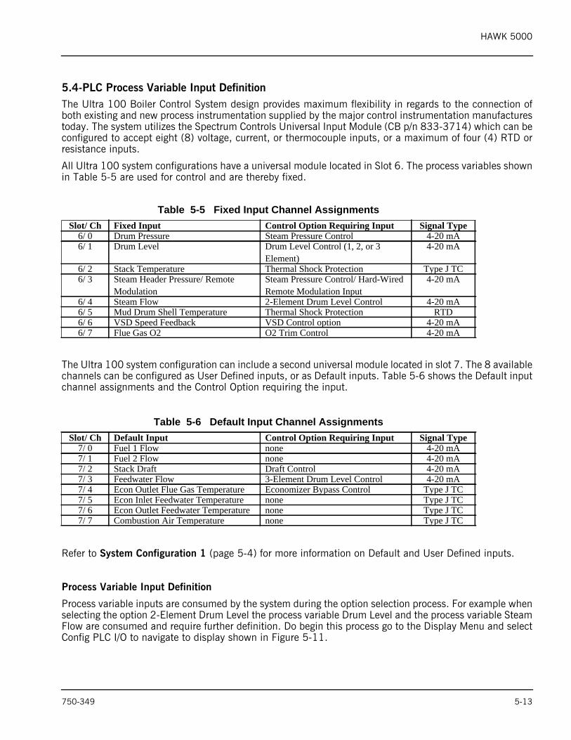
Process variable inputs are consumed by the system during the option selection process. For example whenselecting the option 2-Element Drum Level the process variable Drum Level and the process variable SteamFlow are consumed and require further definition. Do begin this process go to the Display Menu and selectConfig PLC I/O to navigate to display shown in Figure 5-11.
Table 5-5 Fixed Input Channel AssignmentsSlot/ Ch Fixed Input Control Option Requiring Input Signal Type
6/ 0 Drum Pressure Steam Pressure Control 4-20 mA6/ 1 Drum Level Drum Level Control (1, 2, or 3
Element)4-20 mA
6/ 2 Stack Temperature Thermal Shock Protection Type J TC6/ 3 Steam Header Pressure/ Remote
ModulationSteam Pressure Control/ Hard-Wired Remote Modulation Input
4-20 mA
6/ 4 Steam Flow 2-Element Drum Level Control 4-20 mA6/ 5 Mud Drum Shell Temperature Thermal Shock Protection RTD6/ 6 VSD Speed Feedback VSD Control option 4-20 mA6/ 7 Flue Gas O2 O2 Trim Control 4-20 mA
Table 5-6 Default Input Channel AssignmentsSlot/ Ch Default Input Control Option Requiring Input Signal Type
7/ 0 Fuel 1 Flow none 4-20 mA7/ 1 Fuel 2 Flow none 4-20 mA7/ 2 Stack Draft Draft Control 4-20 mA7/ 3 Feedwater Flow 3-Element Drum Level Control 4-20 mA7/ 4 Econ Outlet Flue Gas Temperature Economizer Bypass Control Type J TC7/ 5 Econ Inlet Feedwater Temperature none Type J TC7/ 6 Econ Outlet Feedwater Temperature none Type J TC7/ 7 Combustion Air Temperature none Type J TC
750-349 5-13
HAWK 5000
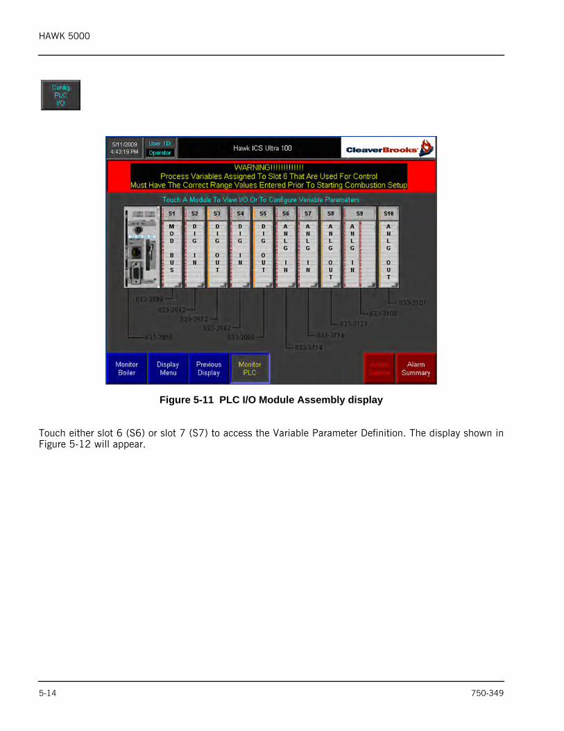
Figure 5-11 PLC I/O Module Assembly display
Touch either slot 6 (S6) or slot 7 (S7) to access the Variable Parameter Definition. The display shown inFigure 5-12 will appear.
5-14 750-349
HAWK 5000
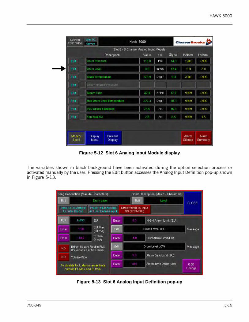
Figure 5-12 Slot 6 Analog Input Module display
The variables shown in black background have been activated during the option selection process oractivated manually by the user. Pressing the Edit button accesses the Analog Input Definition pop-up shownin Figure 5-13.
Figure 5-13 Slot 6 Analog Input Definition pop-up
750-349 5-15
HAWK 5000
Figure 5-13 shows the Analog Input Definition for the process variable ‘Drum Level’. Values have beenentered for the following parameters:
• EU – Engineering Units• EUMax – Value of input at 20 mA in engineering units• EUMin – Value of input at 4 mA in engineering units • HIGH Alarm Limit – in engineering units• HIGH Alarm Description• LOW Alarm Limit – in engineering units• LOW Alarm Description• Alarm Deadband• Alarm Time Delay
For variables of type ‘flow’ the following additional controls are provided:
• Extract Square Root in PLC (differential pressure flow instruments)• Flow Totalization
Table 5-7 Process Variables used for ControlSlot/ Ch Process Variable Control Option
6/ 0 Drum Pressure Drum Pressure Control6/ 1 Drum Level 1, 2, or 3 Element Drum Level Control6/ 2 Stack Temperature Thermal Shock Protection6/ 3 Steam Header Pressure Steam Header Pressure Control6/ 4 Steam Flow 2 or 3 Element Drum Level Control6/ 5 Mud Drum Shell Temperature Thermal Shock Protection6/ 6 VSD Speed Feedback VSD Control6/ 7 Flue Gas O2 O2 Trim7/ 2 Stack Draft Draft Control7/ 3 Feedwater Flow 3 Element Drum Level Control7/ 4 Econ Outlet Flue Gas Temp Economizer Bypass Control
Certain process variables used for control must be properly defined prior to commissioning theboiler. The variables requiring definition will vary depending on the options selected.Undefined variables will produce a warning message on the Main Menu as shown below.
Table 5-7 lists all of the process variables that fall into this category along with the associatedcontrol options.
5-16 750-349
HAWK 5000
6. FUEL COMMISSIONING PROCESS6.1-IntroductionFuel Commissioning is required in systems where the Parallel Combustion Control option is selected. FuelCommissioning is not required for the Single-Point Combustion Control option. Proceed to Appendix E–Boiler START/ STOP Sequence for the steps to follow when commissioning a Single-Point system.
Fuel Commissioning is only possible after all of the process variables associated with the control of theboiler are properly configured. For a full list of these process variables and the control loops involved, referto Table 5-7. The actual process variables requiring configuration are fully dependent on the optionsselected in the System Configuration process. Refer to Section 5 for a full discussion of that process.
The Fuel Commissioning process consists of three steps: Actuator Calibration, Set Combustion, and ControlLoop Tuning.
6.2-Actuator CalibrationOn new boiler installations actuator travel will be preset from the factory for 90 degrees rotation. On serviceconversions the actuators are shipped loose and will require setting of the actuator stroke.
Refer to Appendix D – Procedure To Set Actuator Stroke for details.
After setting the stroke, the actuator is ready for calibration. The Actuator Calibration process is required toidentify the range of travel of an actuator in terms of its feedback voltage signal when the actuator isconnected to its final control element (i.e. fuel valve or air damper).
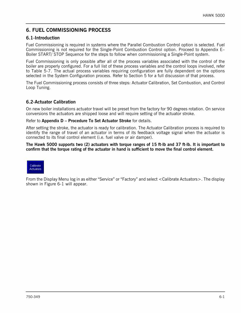
The Hawk 5000 supports two (2) actuators with torque ranges of 15 ft-lb and 37 ft-lb. It is important toconfirm that the torque rating of the actuator in hand is sufficient to move the final control element.
From the Display Menu log in as either “Service” or “Factory” and select <Calibrate Actuators>. The displayshown in Figure 6-1 will appear.
750-349 6-1
HAWK 5000
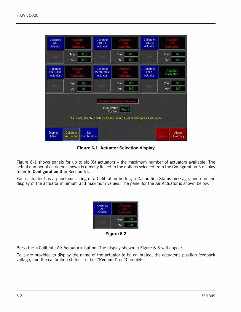
Figure 6-1 Actuator Selection display
Figure 6-1 shows panels for up to six (6) actuators – the maximum number of actuators available. Theactual number of actuators shown is directly linked to the options selected from the Configuration 3 display(refer to Configuration 3 in Section 5).
Each actuator has a panel consisting of a Calibration button, a Calibration Status message, and numericdisplay of the actuator minimum and maximum values. The panel for the Air Actuator is shown below.
Figure 6-2
Press the <Calibrate Air Actuator> button. The display shown in Figure 6-3 will appear.
Cells are provided to display the name of the actuator to be calibrated, the actuator’s position feedbackvoltage, and the calibration status – either “Required” or “Complete”.
6-2 750-349
HAWK 5000
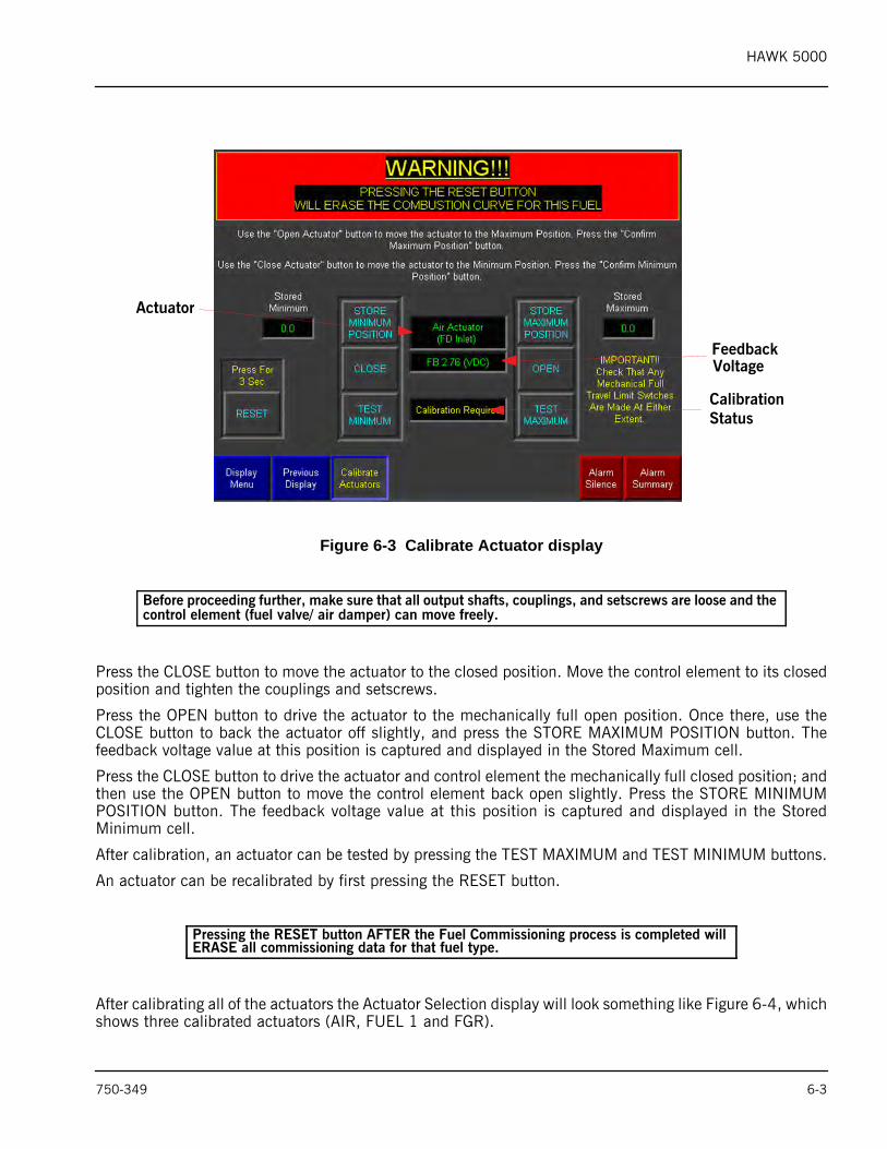
Figure 6-3 Calibrate Actuator display
Press the CLOSE button to move the actuator to the closed position. Move the control element to its closedposition and tighten the couplings and setscrews.
Press the OPEN button to drive the actuator to the mechanically full open position. Once there, use theCLOSE button to back the actuator off slightly, and press the STORE MAXIMUM POSITION button. Thefeedback voltage value at this position is captured and displayed in the Stored Maximum cell.
Press the CLOSE button to drive the actuator and control element the mechanically full closed position; andthen use the OPEN button to move the control element back open slightly. Press the STORE MINIMUMPOSITION button. The feedback voltage value at this position is captured and displayed in the StoredMinimum cell.
After calibration, an actuator can be tested by pressing the TEST MAXIMUM and TEST MINIMUM buttons.
An actuator can be recalibrated by first pressing the RESET button.
After calibrating all of the actuators the Actuator Selection display will look something like Figure 6-4, whichshows three calibrated actuators (AIR, FUEL 1 and FGR).
Before proceeding further, make sure that all output shafts, couplings, and setscrews are loose and the control element (fuel valve/ air damper) can move freely.
Pressing the RESET button AFTER the Fuel Commissioning process is completed will ERASE all commissioning data for that fuel type.
Actuator
FeedbackVoltage
CalibrationStatus
750-349 6-3
HAWK 5000
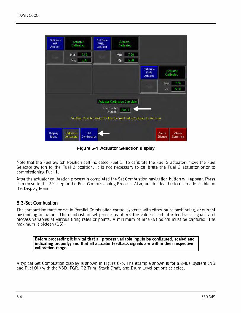
Figure 6-4 Actuator Selection display
Note that the Fuel Switch Position cell indicated Fuel 1. To calibrate the Fuel 2 actuator, move the FuelSelector switch to the Fuel 2 position. It is not necessary to calibrate the Fuel 2 actuator prior tocommissioning Fuel 1.
After the actuator calibration process is completed the Set Combustion navigation button will appear. Pressit to move to the 2nd step in the Fuel Commissioning Process. Also, an identical button is made visible onthe Display Menu.
6.3-Set CombustionThe combustion must be set in Parallel Combustion control systems with either pulse positioning, or currentpositioning actuators. The combustion set process captures the value of actuator feedback signals andprocess variables at various firing rates or points. A minimum of nine (9) points must be captured. Themaximum is sixteen (16).
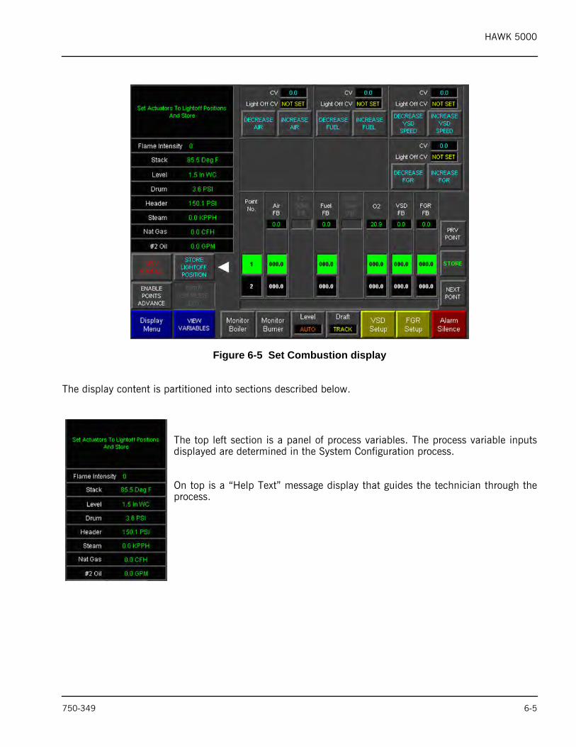
A typical Set Combustion display is shown in Figure 6-5. The example shown is for a 2-fuel system (NGand Fuel Oil) with the VSD, FGR, O2 Trim, Stack Draft, and Drum Level options selected.
Before proceeding it is vital that all process variable inputs be configured, scaled and indicating properly; and that all actuator feedback signals are within their respective calibration range.
6-4 750-349
HAWK 5000
Figure 6-5 Set Combustion display
The display content is partitioned into sections described below.
The top left section is a panel of process variables. The process variable inputsdisplayed are determined in the System Configuration process.
On top is a “Help Text” message display that guides the technician through theprocess.
750-349 6-5
HAWK 5000
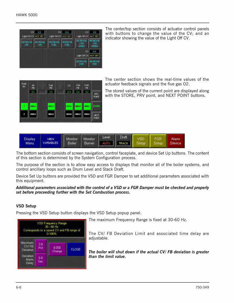
The center/top section consists of actuator control panelswith buttons to change the value of the CV; and anindicator showing the value of the Light Off CV.
The center section shows the real-time values of theactuator feedback signals and the flue gas O2.
The stored values of the current point are displayed alongwith the STORE, PRV point, and NEXT POINT buttons.
The bottom section consists of screen navigation, control faceplate, and device Set Up buttons. The contentof this section is determined by the System Configuration process.
The purpose of the section is to allow easy access to displays that monitor all of the boiler systems, andcontrol ancillary loops such as Drum Level and Stack Draft.
Device Set Up buttons are provided the VSD and FGR Damper to set additional parameters associated withthis equipment.
Additional parameters associated with the control of a VSD or a FGR Damper must be checked and properlyset before proceeding further with the Set Combustion process.
VSD Setup
Pressing the VSD Setup button displays the VSD Setup popup panel.
The maximum Frequency Range is fixed at 30-60 Hz.
The CV/ FB Deviation Limit and associated time delay areadjustable.
The boiler will shut down if the actual CV/ FB deviation is greaterthan the limit value.
6-6 750-349
HAWK 5000
FGR Setup
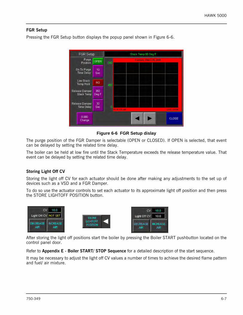
Pressing the FGR Setup button displays the popup panel shown in Figure 6-6.
Figure 6-6 FGR Setup dislayThe purge position of the FGR Damper is selectable (OPEN or CLOSED). If OPEN is selected, that eventcan be delayed by setting the related time delay.
The boiler can be held at low fire until the Stack Temperature exceeds the release temperature value. Thatevent can be delayed by setting the related time delay.
Storing Light Off CV
Storing the light off CV for each actuator should be done after making any adjustments to the set up ofdevices such as a VSD and a FGR Damper.
To do so use the actuator controls to set each actuator to its approximate light off position and then pressthe STORE LIGHTOFF POSITION button.
After storing the light off positions start the boiler by pressing the Boiler START pushbutton located on thecontrol panel door.
Refer to Appendix E - Boiler START/ STOP Sequence for a detailed description of the start sequence.
It may be necessary to adjust the light off CV values a number of times to achieve the desired flame patternand fuel/ air mixture.
750-349 6-7
HAWK 5000
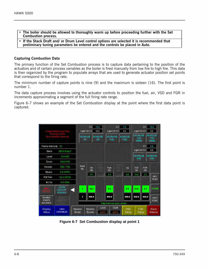
Capturing Combustion Data
The primary function of the Set Combustion process is to capture data pertaining to the position of theactuators and of certain process variables as the boiler is fired manually from low fire to high fire. This datais then organized by the program to populate arrays that are used to generate actuator position set pointsthat correspond to the firing rate.
The minimum number of capture points is nine (9) and the maximum is sixteen (16). The first point isnumber 1.
The data capture process involves using the actuator controls to position the fuel, air, VSD and FGR inincrements approximating a segment of the full firing rate range.
Figure 6-7 shows an example of the Set Combustion display at the point where the first data point iscaptured.
Figure 6-7 Set Combustion display at point 1
• The boiler should be allowed to thoroughly warm up before proceeding further with the Set Combustion process.
• If the Stack Draft and/ or Drum Level control options are selected it is recommended that preliminary tuning parameters be entered and the controls be placed in Auto.
6-8 750-349
HAWK 5000
The STORE button has been pressed as indicated by the text message “Data Point has been stored”. Theactuator CV values have changed from their respective light off values as have the feedback values. Theprocess variables O2, Steam Flow, Gas Flow, Drum and Header Pressure have also changed.
The Drum Level and Stack Draft control loops are in Auto.
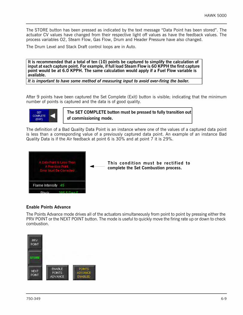
After 9 points have been captured the Set Complete (Exit) button is visible; indicating that the minimumnumber of points is captured and the data is of good quality.
The definition of a Bad Quality Data Point is an instance where one of the values of a captured data pointis less than a corresponding value of a previously captured data point. An example of an instance BadQuality Data is if the Air feedback at point 6 is 30% and at point 7 it is 29%.
Enable Points Advance
The Points Advance mode drives all of the actuators simultaneously from point to point by pressing either the PRV POINT or the NEXT POINT button. The mode is useful to quickly move the firing rate up or down to check combustion.
It is recommended that a total of ten (10) points be captured to simplify the calculation of input at each capture point. For example, if full load Steam Flow is 60 KPPH the first capture point would be at 6.0 KPPH. The same calculation would apply if a Fuel Flow variable is available.It is important to have some method of measuring input to avoid over-firing the boiler.
The SET COMPLETE button must be pressed to fully transition out of commissioning mode.
This condit ion must be rect i f ied tocomplete the Set Combustion process.
750-349 6-9
HAWK 5000
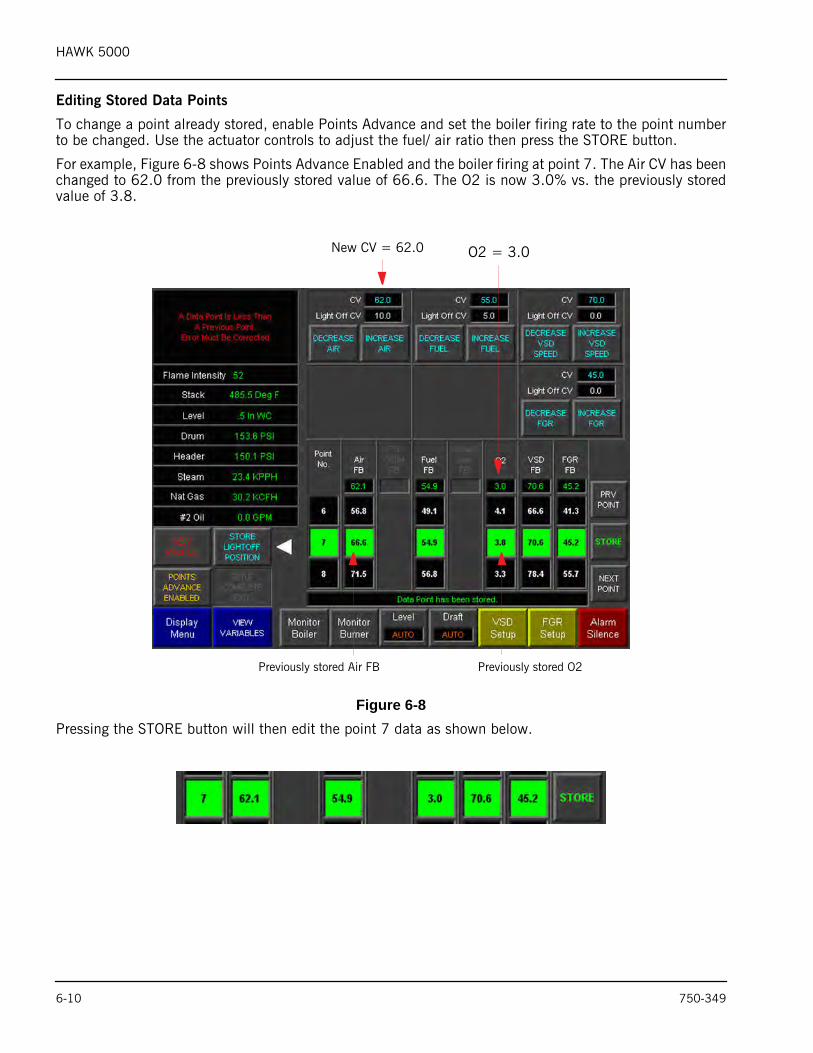
Editing Stored Data Points
To change a point already stored, enable Points Advance and set the boiler firing rate to the point numberto be changed. Use the actuator controls to adjust the fuel/ air ratio then press the STORE button.
For example, Figure 6-8 shows Points Advance Enabled and the boiler firing at point 7. The Air CV has beenchanged to 62.0 from the previously stored value of 66.6. The O2 is now 3.0% vs. the previously storedvalue of 3.8.
Figure 6-8 Pressing the STORE button will then edit the point 7 data as shown below.
New CV = 62.0 O2 = 3.0
Previously stored Air FB Previously stored O2
6-10 750-349
HAWK 5000
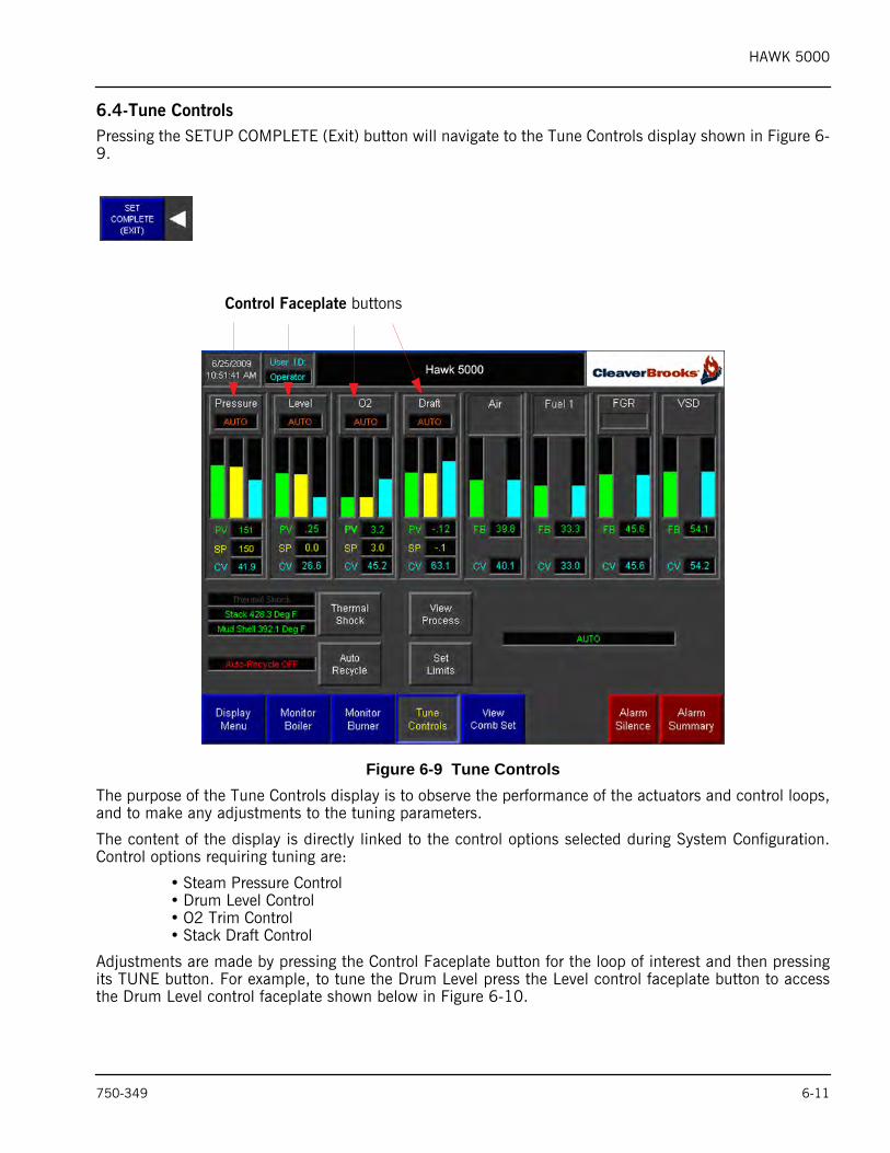
6.4-Tune ControlsPressing the SETUP COMPLETE (Exit) button will navigate to the Tune Controls display shown in Figure 6-9.
Figure 6-9 Tune ControlsThe purpose of the Tune Controls display is to observe the performance of the actuators and control loops,and to make any adjustments to the tuning parameters.
The content of the display is directly linked to the control options selected during System Configuration.Control options requiring tuning are:
• Steam Pressure Control• Drum Level Control• O2 Trim Control• Stack Draft Control
Adjustments are made by pressing the Control Faceplate button for the loop of interest and then pressingits TUNE button. For example, to tune the Drum Level press the Level control faceplate button to accessthe Drum Level control faceplate shown below in Figure 6-10.
Control Faceplate buttons
750-349 6-11
HAWK 5000
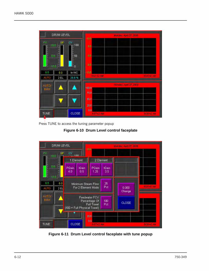
Figure 6-10 Drum Level control faceplate
Figure 6-11 Drum Level control faceplate with tune popup
Press TUNE to access the tuning parameter popup
6-12 750-349
HAWK 5000
7. OPERATING THE BOILER FROM THE HUMAN MACHINE INTERFACE7.1-IntroductionThe Cleaver-Brooks Hawk 5000 utilizes a 10” color touch-screen Human Machine Interface (HMI)programmed to combine the monitoring of the Combustion Control and Burner Management Control intoone user interface.
In addition to monitoring these systems, the HMI is programmed to service all incoming alarms, and toprovide the operator with controls to adjust set points and other performance parameters; and to enablecontrol functions as Auto-Recycle and Thermal Shock Protection.
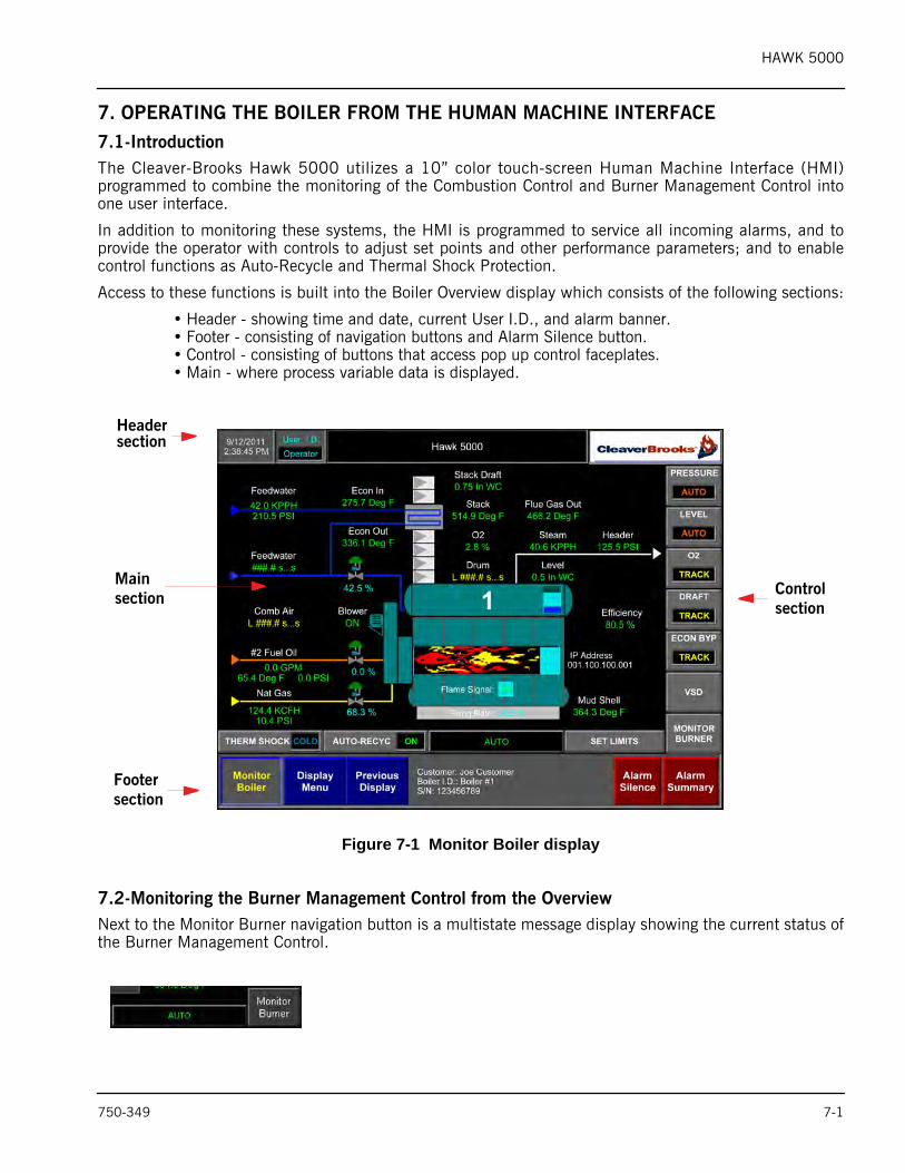
Access to these functions is built into the Boiler Overview display which consists of the following sections:
• Header - showing time and date, current User I.D., and alarm banner.• Footer - consisting of navigation buttons and Alarm Silence button.• Control - consisting of buttons that access pop up control faceplates.• Main - where process variable data is displayed.
Figure 7-1 Monitor Boiler display
7.2-Monitoring the Burner Management Control from the OverviewNext to the Monitor Burner navigation button is a multistate message display showing the current status ofthe Burner Management Control.
Headersection
Mainsection
Footersection
Controlsection
750-349 7-1
HAWK 5000
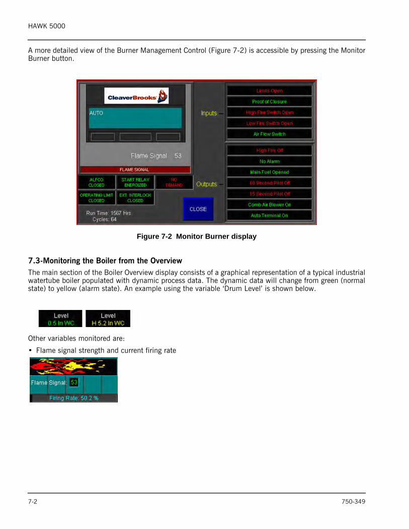
A more detailed view of the Burner Management Control (Figure 7-2) is accessible by pressing the MonitorBurner button.
Figure 7-2 Monitor Burner display
7.3-Monitoring the Boiler from the OverviewThe main section of the Boiler Overview display consists of a graphical representation of a typical industrialwatertube boiler populated with dynamic process data. The dynamic data will change from green (normalstate) to yellow (alarm state). An example using the variable ‘Drum Level’ is shown below.
Other variables monitored are:
• Flame signal strength and current firing rate
7-2 750-349
HAWK 5000
• Output signals to control valves & blower motor status
• Processor IP Address, Run Time, # of Cycles
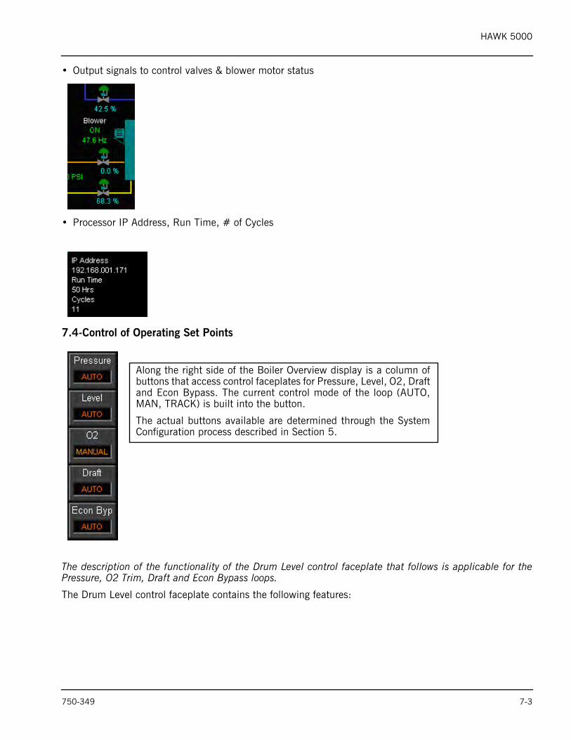
7.4-Control of Operating Set Points
The description of the functionality of the Drum Level control faceplate that follows is applicable for thePressure, O2 Trim, Draft and Econ Bypass loops.
The Drum Level control faceplate contains the following features:
Along the right side of the Boiler Overview display is a column ofbuttons that access control faceplates for Pressure, Level, O2, Draftand Econ Bypass. The current control mode of the loop (AUTO,MAN, TRACK) is built into the button.
The actual buttons available are determined through the SystemConfiguration process described in Section 5.
750-349 7-3
HAWK 5000
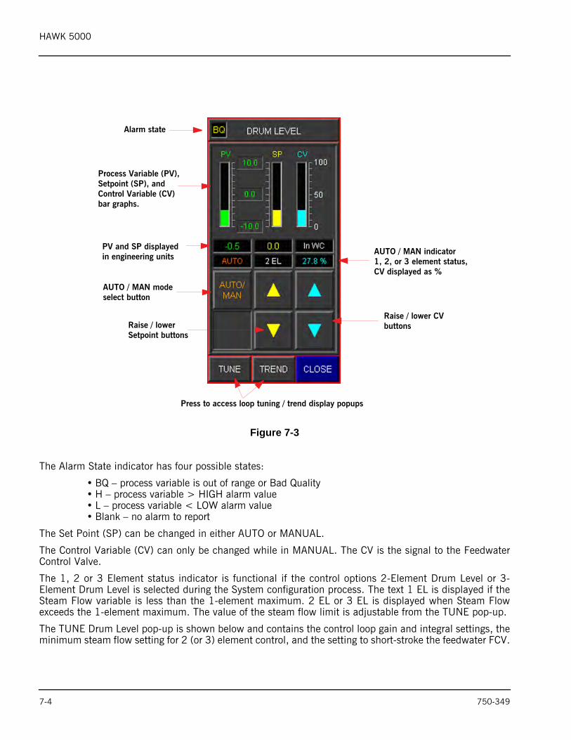
Figure 7-3
The Alarm State indicator has four possible states:
• BQ – process variable is out of range or Bad Quality• H – process variable > HIGH alarm value• L – process variable < LOW alarm value• Blank – no alarm to report
The Set Point (SP) can be changed in either AUTO or MANUAL.
The Control Variable (CV) can only be changed while in MANUAL. The CV is the signal to the FeedwaterControl Valve.
The 1, 2 or 3 Element status indicator is functional if the control options 2-Element Drum Level or 3-Element Drum Level is selected during the System configuration process. The text 1 EL is displayed if theSteam Flow variable is less than the 1-element maximum. 2 EL or 3 EL is displayed when Steam Flowexceeds the 1-element maximum. The value of the steam flow limit is adjustable from the TUNE pop-up.
The TUNE Drum Level pop-up is shown below and contains the control loop gain and integral settings, theminimum steam flow setting for 2 (or 3) element control, and the setting to short-stroke the feedwater FCV.
Alarm state
Process Variable (PV),Setpoint (SP), and Control Variable (CV)bar graphs.
PV and SP displayedin engineering units
AUTO / MAN modeselect button
AUTO / MAN indicator1, 2, or 3 element status,CV displayed as %
Raise / lowerSetpoint buttons
Raise / lower CVbuttons
Press to access loop tuning / trend display popups
7-4 750-349
HAWK 5000
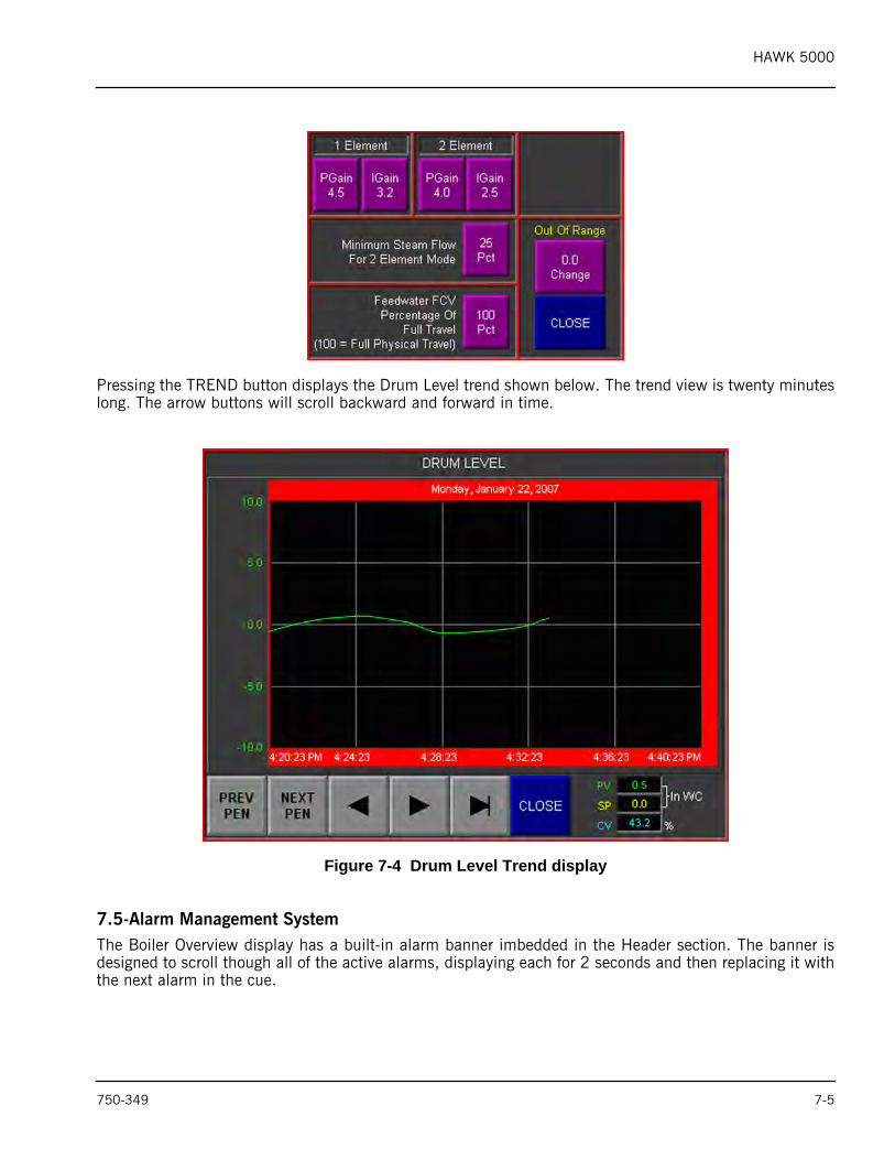
Pressing the TREND button displays the Drum Level trend shown below. The trend view is twenty minuteslong. The arrow buttons will scroll backward and forward in time.
Figure 7-4 Drum Level Trend display
7.5-Alarm Management SystemThe Boiler Overview display has a built-in alarm banner imbedded in the Header section. The banner isdesigned to scroll though all of the active alarms, displaying each for 2 seconds and then replacing it withthe next alarm in the cue.
750-349 7-5
HAWK 5000
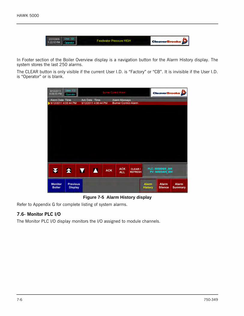
In Footer section of the Boiler Overview display is a navigation button for the Alarm History display. Thesystem stores the last 250 alarms.
The CLEAR button is only visible if the current User I.D. is “Factory” or “CB”. It is invisible if the User I.D.is “Operator” or is blank.
Figure 7-5 Alarm History displayRefer to Appendix G for complete listing of system alarms.
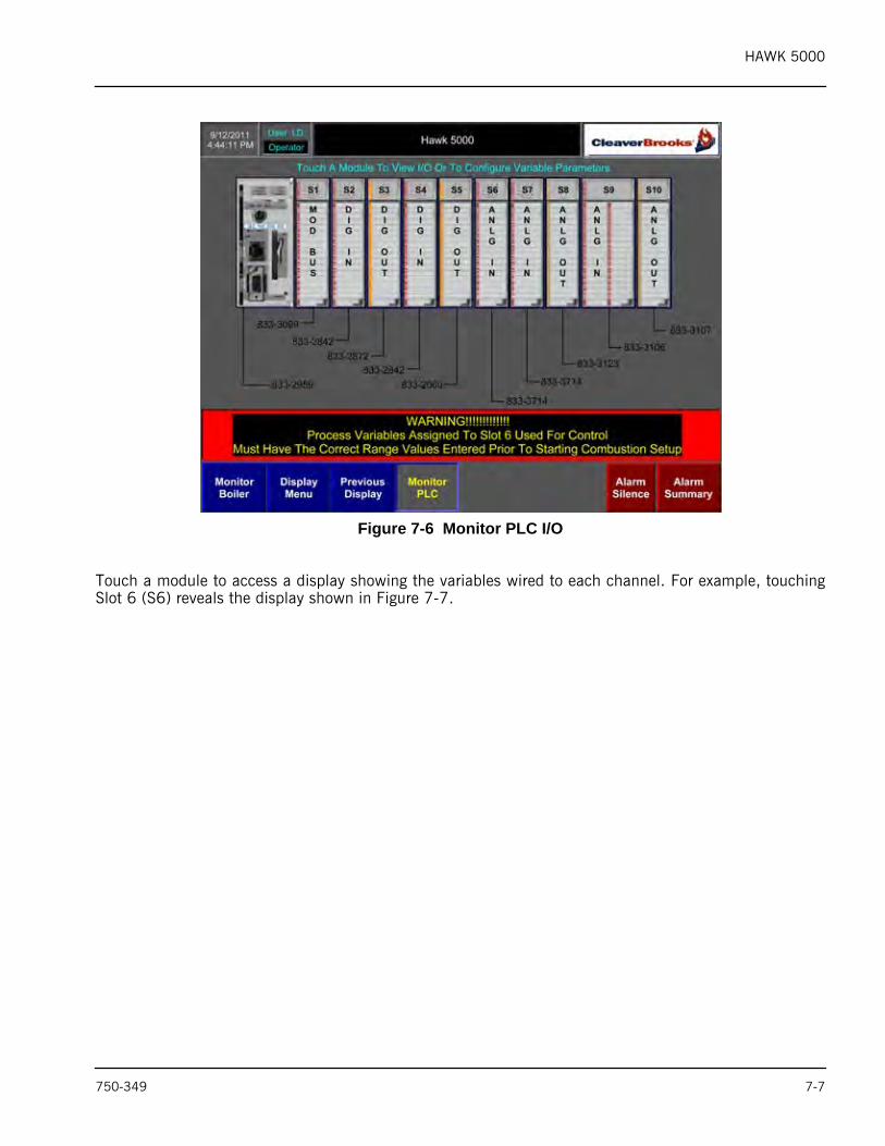
7.6- Monitor PLC I/OThe Monitor PLC I/O display monitors the I/O assigned to module channels.
7-6 750-349
HAWK 5000
Figure 7-6 Monitor PLC I/O
Touch a module to access a display showing the variables wired to each channel. For example, touchingSlot 6 (S6) reveals the display shown in Figure 7-7.
750-349 7-7
HAWK 5000
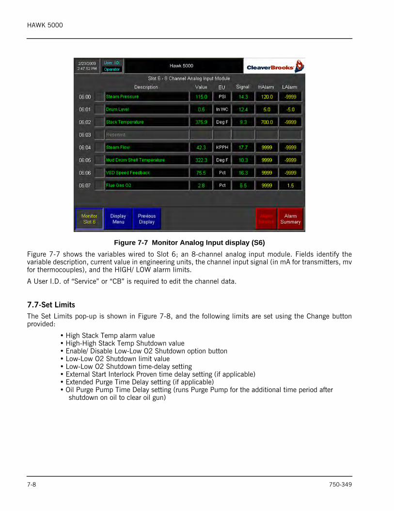
Figure 7-7 Monitor Analog Input display (S6)Figure 7-7 shows the variables wired to Slot 6; an 8-channel analog input module. Fields identify thevariable description, current value in engineering units, the channel input signal (in mA for transmitters, mvfor thermocouples), and the HIGH/ LOW alarm limits.
A User I.D. of “Service” or “CB” is required to edit the channel data.
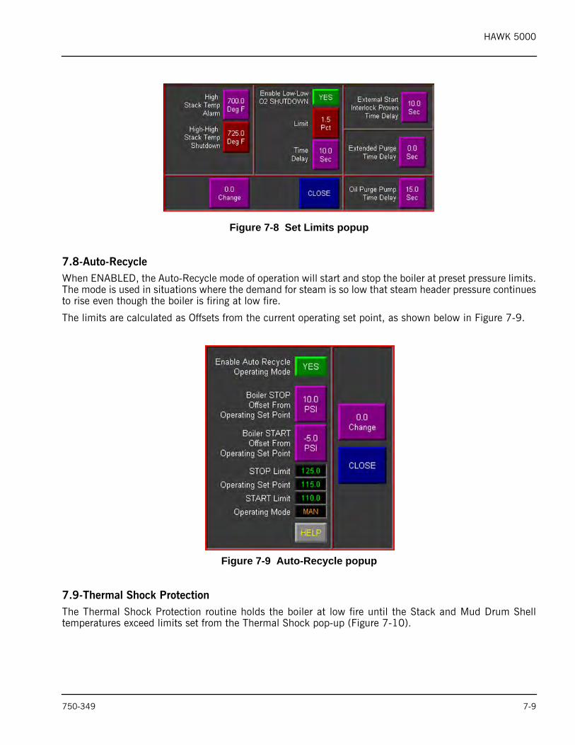
7.7-Set LimitsThe Set Limits pop-up is shown in Figure 7-8, and the following limits are set using the Change buttonprovided:
• High Stack Temp alarm value• High-High Stack Temp Shutdown value • Enable/ Disable Low-Low O2 Shutdown option button• Low-Low O2 Shutdown limit value• Low-Low O2 Shutdown time-delay setting• External Start Interlock Proven time delay setting (if applicable)• Extended Purge Time Delay setting (if applicable)• Oil Purge Pump Time Delay setting (runs Purge Pump for the additional time period after
shutdown on oil to clear oil gun)
7-8 750-349
HAWK 5000
Figure 7-8 Set Limits popup
7.8-Auto-RecycleWhen ENABLED, the Auto-Recycle mode of operation will start and stop the boiler at preset pressure limits.The mode is used in situations where the demand for steam is so low that steam header pressure continuesto rise even though the boiler is firing at low fire.
The limits are calculated as Offsets from the current operating set point, as shown below in Figure 7-9.
Figure 7-9 Auto-Recycle popup
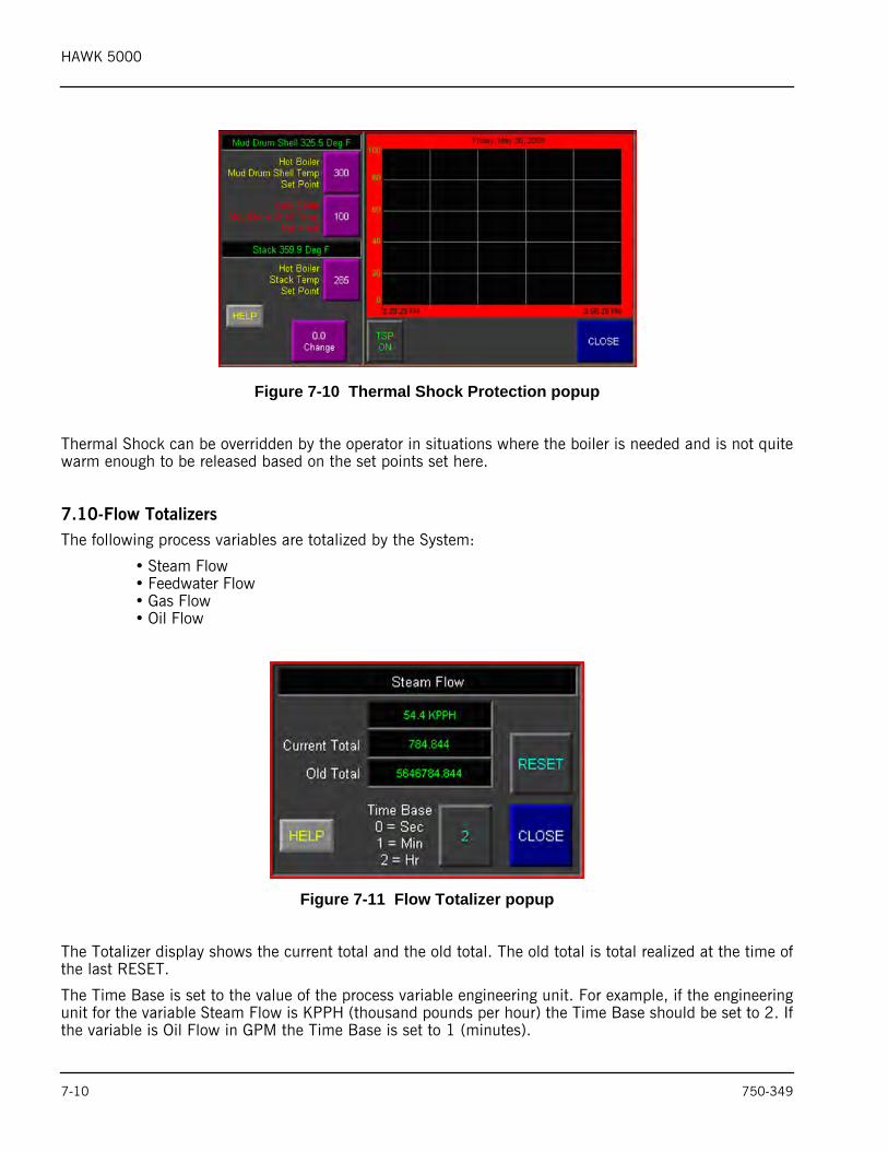
7.9-Thermal Shock ProtectionThe Thermal Shock Protection routine holds the boiler at low fire until the Stack and Mud Drum Shelltemperatures exceed limits set from the Thermal Shock pop-up (Figure 7-10).
750-349 7-9
HAWK 5000
Figure 7-10 Thermal Shock Protection popup
Thermal Shock can be overridden by the operator in situations where the boiler is needed and is not quitewarm enough to be released based on the set points set here.
7.10-Flow TotalizersThe following process variables are totalized by the System:
• Steam Flow• Feedwater Flow• Gas Flow• Oil Flow
Figure 7-11 Flow Totalizer popup
The Totalizer display shows the current total and the old total. The old total is total realized at the time ofthe last RESET.
The Time Base is set to the value of the process variable engineering unit. For example, if the engineeringunit for the variable Steam Flow is KPPH (thousand pounds per hour) the Time Base should be set to 2. Ifthe variable is Oil Flow in GPM the Time Base is set to 1 (minutes).
7-10 750-349
HAWK 5000
8. TROUBLESHOOTINGTo avoid communication problems between the PLC and its associated components, ensure that all unitsare properly assembled on the DIN rail. Two locking tabs attach each module to the rail.
The PLC, power supply, and I/O modules are connected to each other with module bus locking levers. Alllocking levers should be completely to the left. Unlocked levers will cause the modules to the right of theunlocked lever to be disabled.
8.1-Processor (PLC)The PLC has a key switch which is used for programming purposes. The key should not be kept in the PLCbut should be available in the cabinet for service personnel. If the key is installed while the system isoperating, the key switch must be in the RUN position.
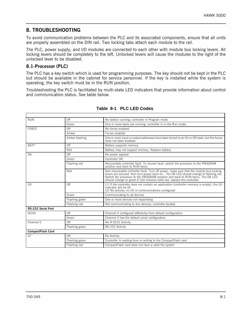
Troubleshooting the PLC is facilitated by multi-state LED indicators that provide information about controland communication status. See table below.
Table 8-1 PLC LED Codes
RUN Off No task(s) running; controller in Program mode
Green One or more tasks are running; controller is in the Run mode.
FORCE Off No forces enabled
Amber Forces enabled
Amber flashing One or more input or output addresses have been forced to an On or Off state, but the forces have not been enabled.
BATT Off Battery supports memory
Red Battery may not support memory. Replace battery.
OK Off No power applied
Green Controller OK
Flashing red Recoverable controller fault. To recover fault, switch the processor to the PROGRAM position and back to RUN twice.
Red Non-recoverable controller fault: Turn off power, make sure that the module bus locking levers are secured, then turn power back on.. The OK LED should change to flashing red. Switch the processor to the PROGRAM position and back to RUN twice. The OK LED should change to green.If LED remains solid red, replace the controller.
I/O Off (1) If the controller does not contain an application (controller memory is empty), the I/O indicator will be off.(2) No activity; no I/O or communications configured
Green Communicating to all devices
Flashing green One or more devices not responding
Flashing red Not communicating to any devices; controller faulted.
RS-232 Serial Port
DCH0 Off Channel 0 configured differently from default configuration
Green Channel 0 has the default serial configuration
Channel 0 Off No R-S232 Activity
Flashing green RS-232 Activity
CompactFlash Card
CF Off No Activity
Flashing green Controller is reading from or writing to the CompactFlash card
Flashing red CompactFlash card does not have a valid file system
750-349 8-1
HAWK 5000
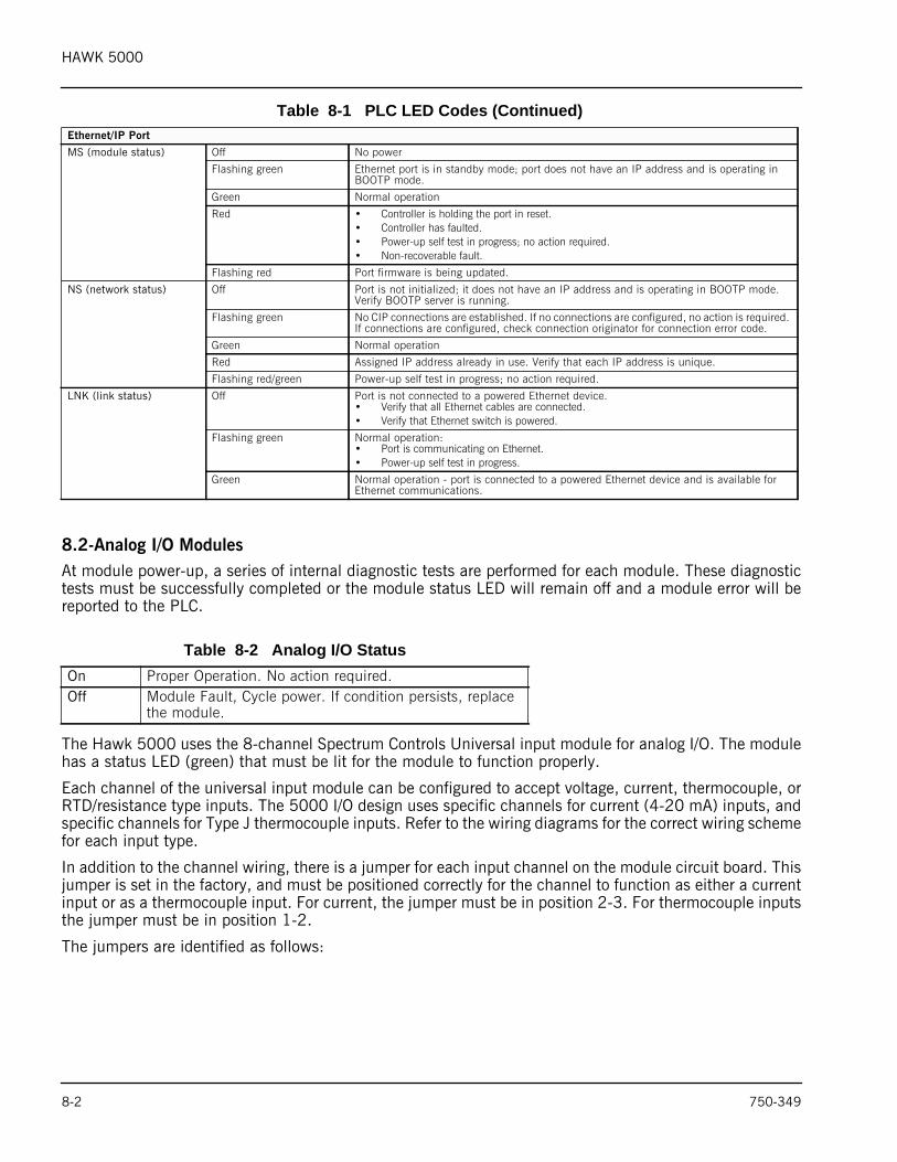
8.2-Analog I/O ModulesAt module power-up, a series of internal diagnostic tests are performed for each module. These diagnostictests must be successfully completed or the module status LED will remain off and a module error will bereported to the PLC.
The Hawk 5000 uses the 8-channel Spectrum Controls Universal input module for analog I/O. The modulehas a status LED (green) that must be lit for the module to function properly.
Each channel of the universal input module can be configured to accept voltage, current, thermocouple, orRTD/resistance type inputs. The 5000 I/O design uses specific channels for current (4-20 mA) inputs, andspecific channels for Type J thermocouple inputs. Refer to the wiring diagrams for the correct wiring schemefor each input type.
In addition to the channel wiring, there is a jumper for each input channel on the module circuit board. Thisjumper is set in the factory, and must be positioned correctly for the channel to function as either a currentinput or as a thermocouple input. For current, the jumper must be in position 2-3. For thermocouple inputsthe jumper must be in position 1-2.
The jumpers are identified as follows:
Ethernet/IP Port
MS (module status) Off No power
Flashing green Ethernet port is in standby mode; port does not have an IP address and is operating in BOOTP mode.
Green Normal operation
Red • Controller is holding the port in reset.• Controller has faulted.• Power-up self test in progress; no action required.• Non-recoverable fault.
Flashing red Port firmware is being updated.
NS (network status) Off Port is not initialized; it does not have an IP address and is operating in BOOTP mode. Verify BOOTP server is running.
Flashing green No CIP connections are established. If no connections are configured, no action is required. If connections are configured, check connection originator for connection error code.
Green Normal operation
Red Assigned IP address already in use. Verify that each IP address is unique.
Flashing red/green Power-up self test in progress; no action required.
LNK (link status) Off Port is not connected to a powered Ethernet device.• Verify that all Ethernet cables are connected.• Verify that Ethernet switch is powered.
Flashing green Normal operation:• Port is communicating on Ethernet.• Power-up self test in progress.
Green Normal operation - port is connected to a powered Ethernet device and is available for Ethernet communications.
Table 8-2 Analog I/O StatusOn Proper Operation. No action required.Off Module Fault, Cycle power. If condition persists, replace
the module.
Table 8-1 PLC LED Codes (Continued)
8-2 750-349
HAWK 5000
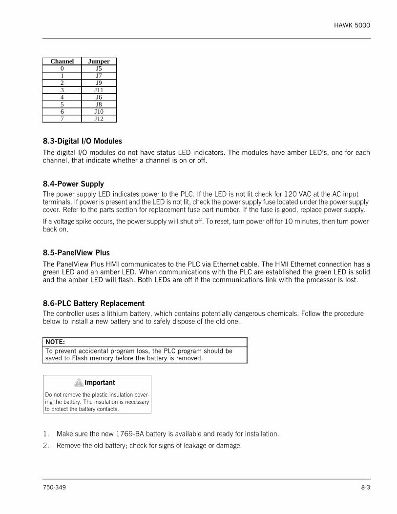
8.3-Digital I/O ModulesThe digital I/O modules do not have status LED indicators. The modules have amber LED’s, one for eachchannel, that indicate whether a channel is on or off.
8.4-Power SupplyThe power supply LED indicates power to the PLC. If the LED is not lit check for 120 VAC at the AC input terminals. If power is present and the LED is not lit, check the power supply fuse located under the power supply cover. Refer to the parts section for replacement fuse part number. If the fuse is good, replace power supply.
If a voltage spike occurs, the power supply will shut off. To reset, turn power off for 10 minutes, then turn power back on.
8.5-PanelView PlusThe PanelView Plus HMI communicates to the PLC via Ethernet cable. The HMI Ethernet connection has agreen LED and an amber LED. When communications with the PLC are established the green LED is solidand the amber LED will flash. Both LEDs are off if the communications link with the processor is lost.
8.6-PLC Battery ReplacementThe controller uses a lithium battery, which contains potentially dangerous chemicals. Follow the procedure below to install a new battery and to safely dispose of the old one.
1. Make sure the new 1769-BA battery is available and ready for installation.
2. Remove the old battery; check for signs of leakage or damage.
Channel Jumper0 J51 J72 J93 J114 J65 J86 J107 J12
NOTE:To prevent accidental program loss, the PLC program should be saved to Flash memory before the battery is removed.
Important!Do not remove the plastic insulation cover-ing the battery. The insulation is necessary to protect the battery contacts.
750-349 8-3
HAWK 5000
3. Install a new 1769-BA battery.
Note: If control power is cycled while battery is removed, the L32E and L35E processors will have immediate program loss.
Note: When the battery LED is red, order a replacement battery immediately (for the L32E and L35E processor part # 808-00020).
4. Write the battery date on the door of the controller.
5. Check the BATTERY LED on the front of the controller:
• If the BATTERY LED is OFF, proceed to step 6.
• If the BATTERY LED remains on after installing a new battery, contact your Cleaver-Brooks representative.
6. Dispose of the old battery according to state and local regulations.
! CautionThe 1769-BA is the only battery compatible with the L32E and L35E controllers. Installing a different battery may damage the controller.
Important!Do not incinerate or dispose of lithium batteries in general trash collection. They may explode or rupture violently. Follow state and local regulations for disposal of these materials. You are legally responsible for hazards created while disposing of your battery.
Warning!When the battery is connected or discon-nected an electrical arc can occur. Ensure that the area is free of explosion hazards before proceeding.
Warning!When replacing battery 110V power is present. Proceed with caution.
8-4 750-349
HAWK 5000
8.7-Boiler will not start (Recycle Limit Relay)PLC logic starts the boiler by energizing the Recycle Limit Relay (RLR) via discrete output on slot 3 channel0. The following conditions must be met to energize the relay:
• Boiler Start pilot light is lit.• External start interlock proven (jumper this input if not used.)• Boiler Outlet Damper proven open (systems with Draft control option only)
8.8-Boiler will not start (Non-Recycle Limit Relay)The NRLR must be energized for the boiler to start, and PLC logic energizes the NRLR via discrete outputon slot 3 channel 2. The following conditions must be met to energize the relay:
• Actuator Calibration process is complete.• Lightoff positions stored.• No RLR fault detected.• Actuators proven in lightoff positions.• Combustion curve data integrity check passed. (Parallel systems only)• No I/O module fault detected.• No Burner Control alarm detected.• Major control options have been selected. (parallel or single-point; pulse or current positioning) • No Low-Low O2 condition detected. (systems with O2 analyzer and Low-Low O2 Shutdown option
turned on.)• No High-High Furnace Pressure condition detected.• No High-High Stack Temperature condition detected. (systems with Stack Temperature input activated
and High-High Stack Temp shutdown option turned on)
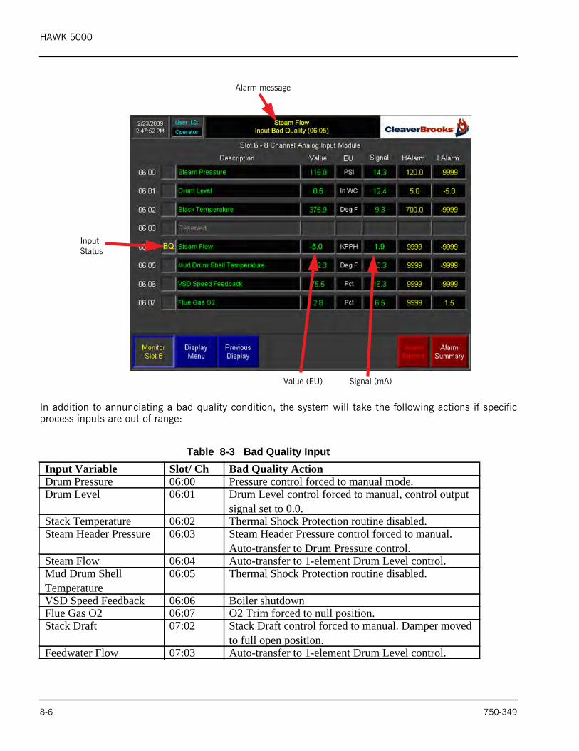
8.9-Analog Input Channel Bad QualityEach analog input is continuously checked for signal quality. Good quality inputs are within the range of3.2 to 20.7 mA, and a bad quality input would fall outside of these limits.
If an input is detected as bad quality the condition is annunciated and the status text “BQ” displayed. Thefigure below shows the input ‘Steam Flow’ as bad quality.
750-349 8-5
HAWK 5000
In addition to annunciating a bad quality condition, the system will take the following actions if specificprocess inputs are out of range:
Table 8-3 Bad Quality Input Input Variable Slot/ Ch Bad Quality ActionDrum Pressure 06:00 Pressure control forced to manual mode.Drum Level 06:01 Drum Level control forced to manual, control output
signal set to 0.0.Stack Temperature 06:02 Thermal Shock Protection routine disabled.Steam Header Pressure 06:03 Steam Header Pressure control forced to manual.
Auto-transfer to Drum Pressure control. Steam Flow 06:04 Auto-transfer to 1-element Drum Level control.Mud Drum Shell Temperature
06:05 Thermal Shock Protection routine disabled.
VSD Speed Feedback 06:06 Boiler shutdownFlue Gas O2 06:07 O2 Trim forced to null position.Stack Draft 07:02 Stack Draft control forced to manual. Damper moved
to full open position.Feedwater Flow 07:03 Auto-transfer to 1-element Drum Level control.
Alarm message
Input Status
Value (EU) Signal (mA)
8-6 750-349
HAWK 5000
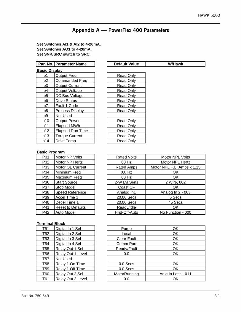
Appendix A — PowerFlex 400 Parameters
Set Switches AI1 & AI2 to 4-20mA.Set Switches AO1 to 4-20mA.Set SNK/SRC switch to SRC.
Par. No. Parameter Name Default Value W/HawkBasic Display
b1 Output Freq Read Onlyb2 Commanded Freq Read Onlyb3 Output Current Read Onlyb4 Output Voltage Read Onlyb5 DC Bus Voltage Read Onlyb6 Drive Status Read Onlyb7 Fault 1 Code Read Onlyb8 Process Display Read Onlyb9 Not Usedb10 Output Power Read Onlyb11 Elapsed MWh Read Onlyb12 Elapsed Run Time Read Onlyb13 Torque Current Read Onlyb14 Drive Temp Read Only
Basic ProgramP31 Motor NP Volts Rated Volts Motor NPL VoltsP32 Motor NP Hertz 60 Hz Motor NPL HertzP33 Motor OL Current Rated Amps Motor NPL F.L. Amps x 1.15P34 Minimum Freq 0.0 Hz OKP35 Maximum Freq 60 Hz OKP36 Start Source 2-W Lvl Sens 2 Wire, 002P37 Stop Mode Coast,CF OKP38 Speed Reference Analog In1 Analog In 2 - 003P39 Accel Time 1 20.00 Secs 5 SecsP40 Decel Time 1 20.00 Secs 45 SecsP41 Reset to Defaults Ready/Idle OKP42 Auto Mode Hnd-Off-Auto No Function - 000
Terminal BlockT51 Digital In 1 Sel Purge OKT52 Digital In 2 Sel Local OKT53 Digital In 3 Sel Clear Fault OKT54 Digital In 4 Sel Comm Port OKT55 Relay Out 1 Sel Ready/Fault OKT56 Relay Out 1 Level 0.0 OKT57 Not UsedT58 Relay 1 On Time 0.0 Secs OKT59 Relay 1 Off Time 0.0 Secs OKT60 Relay Out 2 Sel MotorRunning Anlg In Loss - 011T61 Relay Out 2 Level 0.0 OK
Part No. 750-349 A-1
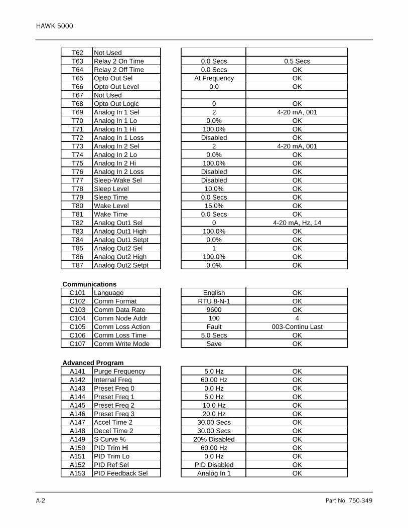
HAWK 5000
T62 Not UsedT63 Relay 2 On Time 0.0 Secs 0.5 SecsT64 Relay 2 Off Time 0.0 Secs OKT65 Opto Out Sel At Frequency OKT66 Opto Out Level 0.0 OKT67 Not UsedT68 Opto Out Logic 0 OKT69 Analog In 1 Sel 2 4-20 mA, 001T70 Analog In 1 Lo 0.0% OKT71 Analog In 1 Hi 100.0% OKT72 Analog In 1 Loss Disabled OKT73 Analog In 2 Sel 2 4-20 mA, 001T74 Analog In 2 Lo 0.0% OKT75 Analog In 2 Hi 100.0% OKT76 Analog In 2 Loss Disabled OKT77 Sleep-Wake Sel Disabled OKT78 Sleep Level 10.0% OKT79 Sleep Time 0.0 Secs OKT80 Wake Level 15.0% OKT81 Wake Time 0.0 Secs OKT82 Analog Out1 Sel 0 4-20 mA, Hz, 14T83 Analog Out1 High 100.0% OKT84 Analog Out1 Setpt 0.0% OKT85 Analog Out2 Sel 1 OKT86 Analog Out2 High 100.0% OKT87 Analog Out2 Setpt 0.0% OK
CommunicationsC101 Language English OKC102 Comm Format RTU 8-N-1 OKC103 Comm Data Rate 9600 OKC104 Comm Node Addr 100 4C105 Comm Loss Action Fault 003-Continu LastC106 Comm Loss Time 5.0 Secs OKC107 Comm Write Mode Save OK
Advanced ProgramA141 Purge Frequency 5.0 Hz OKA142 Internal Freq 60.00 Hz OKA143 Preset Freq 0 0.0 Hz OKA144 Preset Freq 1 5.0 Hz OKA145 Preset Freq 2 10.0 Hz OKA146 Preset Freq 3 20.0 Hz OKA147 Accel Time 2 30.00 Secs OKA148 Decel Time 2 30.00 Secs OKA149 S Curve % 20% Disabled OKA150 PID Trim Hi 60.00 Hz OKA151 PID Trim Lo 0.0 Hz OKA152 PID Ref Sel PID Disabled OKA153 PID Feedback Sel Analog In 1 OK
A-2 Part No. 750-349
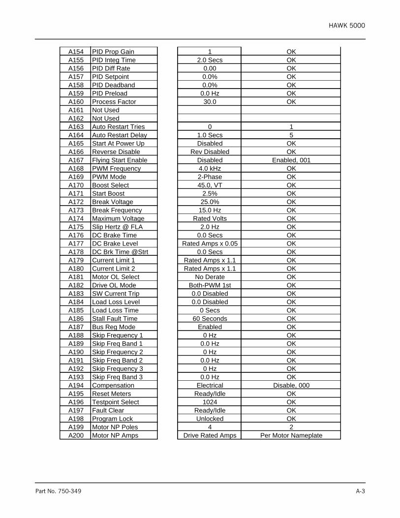
HAWK 5000
A154 PID Prop Gain 1 OKA155 PID Integ Time 2.0 Secs OKA156 PID Diff Rate 0.00 OKA157 PID Setpoint 0.0% OKA158 PID Deadband 0.0% OKA159 PID Preload 0.0 Hz OKA160 Process Factor 30.0 OKA161 Not UsedA162 Not UsedA163 Auto Restart Tries 0 1A164 Auto Restart Delay 1.0 Secs 5A165 Start At Power Up Disabled OKA166 Reverse Disable Rev Disabled OKA167 Flying Start Enable Disabled Enabled, 001A168 PWM Frequency 4.0 kHz OKA169 PWM Mode 2-Phase OKA170 Boost Select 45.0, VT OKA171 Start Boost 2.5% OKA172 Break Voltage 25.0% OKA173 Break Frequency 15.0 Hz OKA174 Maximum Voltage Rated Volts OKA175 Slip Hertz @ FLA 2.0 Hz OKA176 DC Brake Time 0.0 Secs OKA177 DC Brake Level Rated Amps x 0.05 OKA178 DC Brk Time @Strt 0.0 Secs OKA179 Current Limit 1 Rated Amps x 1.1 OKA180 Current Limit 2 Rated Amps x 1.1 OKA181 Motor OL Select No Derate OKA182 Drive OL Mode Both-PWM 1st OKA183 SW Current Trip 0.0 Disabled OKA184 Load Loss Level 0.0 Disabled OKA185 Load Loss Time 0 Secs OKA186 Stall Fault Time 60 Seconds OKA187 Bus Reg Mode Enabled OKA188 Skip Frequency 1 0 Hz OKA189 Skip Freq Band 1 0.0 Hz OKA190 Skip Frequency 2 0 Hz OKA191 Skip Freq Band 2 0.0 Hz OKA192 Skip Frequency 3 0 Hz OKA193 Skip Freq Band 3 0.0 Hz OKA194 Compensation Electrical Disable, 000A195 Reset Meters Ready/Idle OKA196 Testpoint Select 1024 OKA197 Fault Clear Ready/Idle OKA198 Program Lock Unlocked OKA199 Motor NP Poles 4 2A200 Motor NP Amps Drive Rated Amps Per Motor Nameplate
Part No. 750-349 A-3
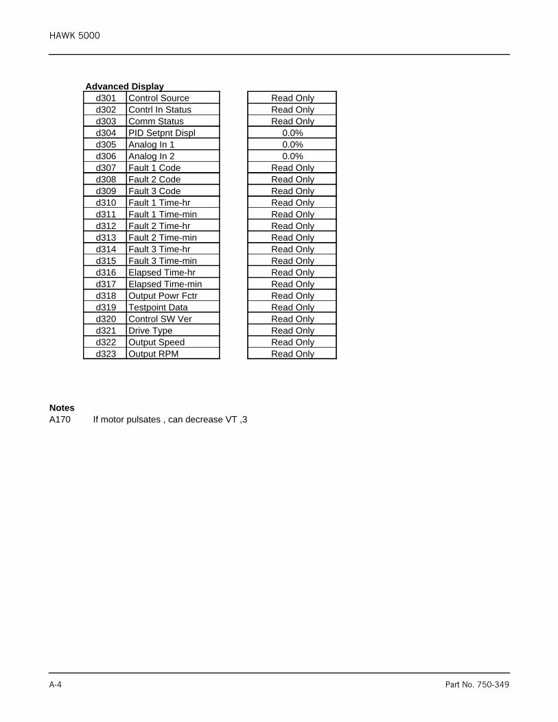
HAWK 5000
Advanced Displayd301 Control Source Read Onlyd302 Contrl In Status Read Onlyd303 Comm Status Read Onlyd304 PID Setpnt Displ 0.0%d305 Analog In 1 0.0%d306 Analog In 2 0.0%d307 Fault 1 Code Read Onlyd308 Fault 2 Code Read Onlyd309 Fault 3 Code Read Onlyd310 Fault 1 Time-hr Read Onlyd311 Fault 1 Time-min Read Onlyd312 Fault 2 Time-hr Read Onlyd313 Fault 2 Time-min Read Onlyd314 Fault 3 Time-hr Read Onlyd315 Fault 3 Time-min Read Onlyd316 Elapsed Time-hr Read Onlyd317 Elapsed Time-min Read Onlyd318 Output Powr Fctr Read Onlyd319 Testpoint Data Read Onlyd320 Control SW Ver Read Onlyd321 Drive Type Read Onlyd322 Output Speed Read Onlyd323 Output RPM Read Only
NotesA170 If motor pulsates , can decrease VT ,3
A-4 Part No. 750-349

HAWK 5000
Part No. 750-349 B-1
Appendix B - Procedure to Load Program and Set Up PanelView Plus HMI
1. Copy the Rockwell Software folder from its location on the server to a compactflash card that you use to load standard Panelviews. There should be nothing else on the card but this folder.
2. Power up the PV+ and insert compact flash card into slot provided.3. Touch Terminal Settings [F4].4. From Terminal Settings, select File Management.5. Select Copy Files.6. Select Copy Applications.7. Using the Source [F1] button, select External Storage 1 (the green bullet should move down to that selection).
Use the up/down buttons to select the application you want to load and then press the Destination [F2] button.8. From the Copy Applications Destination screen, the green bullet should be on Internal Storage. If it’s not it
should be. Press the Copy [F2] button. 9. After the file is copied you should be back in the Copy Applications screen. Press Cancel [F8]. 10. You should now be on the Copy Files screen. Press Close [8].11. You should now be on the File Management screen. Press Close [F8].12. You should now be back on the Terminal Settings screen. Select Networks and Communications.13. From the Networks and Communications screen select Network Connections.14. From the Network Connections screen select Network Adaptors.15. From The Network Adaptors screen press IP Address [F2].16. From the IP Address screen select Use DHCP [F4]. The green bullet should be in the No position and the IP
Address [F1] button should be black.17. Press IP Address [F1] and enter the IP address with the keypad provided. The IWT100 IP addressing scheme
for the PV+ is 192.168.1.181 thru 192.168.1.188 for boilers 1 thru 8. 18. Press Subnet Mask [F2] and enter 255.255.255.00019. Press Gateway [F3] and enter 192.168.1.120. After entering IP Address, Subnet, and Gateway, press the Ok [F7].21. From the Adapters screen press Ok [F7].22. From Network Adaptors screen press Close [F8].23. From the Network Connections screen press Close [F8].24. From the Network and Cnnections screen press Close [F8]. 25. From the Terminal Setting screen press Close [F8]. 26. You should now be on the FactoryTalk View ME Station screen. Press Load Application [F1]. 27. Load the application from Internal Storage by pressing the Load [F2] button.28. You should back on the FactoryTalk View ME Station screen. Press Terminal Settings [F4].29. Select Startup Options and then select FactoryTalk View ME Station Startup.30. Using the On Startup [F1] button, put the green bullet to Run Current Application. Then press Ok [F7].31. You should now be on the Startup Options screen. Press Close [F8].32. You should now be on the Terminal Settings screen. Press Close [F8].
You should now be on the FactoryTalk View ME Station screen. Press Run Application [F2].

HAWK 5000
B-2 Part No. 750-349
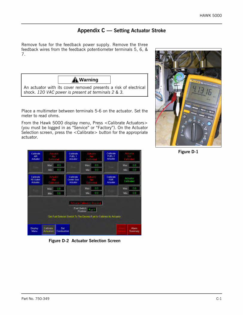
HAWK 5000
Appendix C — Setting Actuator Stroke
Remove fuse for the feedback power supply. Remove the threefeedback wires from the feedback potentiometer terminals 5, 6, &7.
Place a multimeter between terminals 5-6 on the actuator. Set themeter to read ohms.
From the Hawk 5000 display menu, Press <Calibrate Actuators>(you must be logged in as “Service” or “Factory”). On the ActuatorSelection screen, press the <Calibrate> button for the appropriateactuator.
Figure D-2 Actuator Selection Screen
Figure D-1
! WarningAn actuator with its cover removed presents a risk of electricalshock. 120 VAC power is present at terminals 2 & 3.
Part No. 750-349 C-1
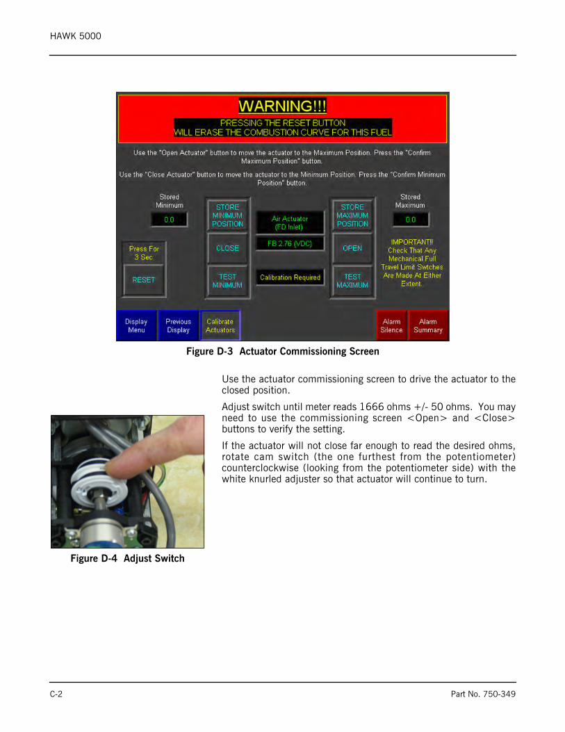
HAWK 5000
Use the actuator commissioning screen to drive the actuator to theclosed position.
Adjust switch until meter reads 1666 ohms +/- 50 ohms. You mayneed to use the commissioning screen <Open> and <Close>buttons to verify the setting.
If the actuator will not close far enough to read the desired ohms,rotate cam switch (the one furthest from the potentiometer)counterclockwise (looking from the potentiometer side) with thewhite knurled adjuster so that actuator will continue to turn.
Figure D-3 Actuator Commissioning Screen
Figure D-4 Adjust Switch
C-2 Part No. 750-349
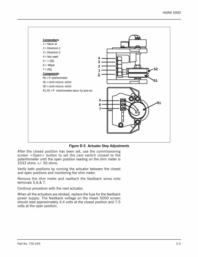
HAWK 5000
After the closed position has been set, use the commissioningscreen <Open> button to set the cam switch closest to thepotentiometer until the open position reading on the ohm meter is3333 ohms +/- 50 ohms.
Verify both positions by running the actuator between the closedand open positions and monitoring the ohm meter.
Remove the ohm meter and reattach the feedback wires ontoterminals 5,6,& 7.
Continue procedure with the next actuator.
When all the actuators are stroked, replace the fuse for the feedbackpower supply. The feedback voltage on the Hawk 5000 screenshould read approximately 4.4 volts at the closed position and 7.5volts at the open position.
Figure D-5 Actuator Stop Adjustments
Connections1 = Neutr al
2 = Direction 1
3 = Direction 2
4 = Not used
5 = + (S2)
6 = Wiper
7 = (S1)
ComponentsR1 = P otentiometer
S1 = Limit micros witch
S2 = Limit micros witch
F1, F2 = P otentiometer secur ity scre ws
4321
R1
S1
S2
567
Part No. 750-349 C-3

HAWK 5000
C-4 Part No. 750-349
HAWK 5000
Appendix D – Hawk 5000 START/ STOP Sequence
To understand fully the sequence of operation, please refer to the following documentation:
• Hawk 5000 Wiring Diagrams
• CB-120E Burner Management Control Manual
• Hawk 5000 Manual
Please note that all terminal numbers that are referenced below are on the wiring base of the Burner Management Control, unless otherwise noted.A constant 120 VAC should be available to the L1-L2 terminals of the wiring base of the Burner Management Control.
Control Panel Primary Components:• Combustion Control System (CCS) Programmable Logic Controller (PLC)
• Burner Management Control
Control Panel Operators and Indicators:• Burner STOP/ RESET Pushbutton PB-112A
• Burner START Pushbutton PB-112B
• Burner START pilot light PL-112
• E-Stop Pushbutton PB-112C
• Atomizing Media Selector Switch
• Fuel Selector Switch H-200
• Proof of Closure Test Pushbutton
• Forced Draft Fan H-O-A Switch HS-217
• Low Water Alarm Light L-308
• High Water Alarm Light L-313
• Alarm Light L-511
Boiler Start Sequence – Firing Natural Gas (Fuel Selector in Gas Position)1. Press Burner START pushbutton PB-112B. Burner START relay CR-112 will energize if the following
conditions are met:• Burner Management Control Lockout relay CR-223 is de-energized.
• E-Stop pushbutton PB-112C not engaged.
• FD Fan Current Sensing Relays CSR-1,2,3 are de-energized.
2. Energizing CR-112 will apply power to Burner Management Control terminal 3 if the following conditions are met:
• Recycle Limit relay CR-502 energized.
• Main Fuel block valves are proved closed (Burner Management Control circuit L1-13 closed).
Part No. 750-349 D-1
HAWK 5000
3. With power applied to terminal 3, the following running interlocks must be satisfied to close Burner Management Control running interlock circuit 3-P:
• Aux Low Water Cutoff (ALWCO)
• Low Water Cutoff #1 (LWCO-1)
• Low Water Cutoff #2 (LWCO-2)
• Low Gas Pressure Switch (LGPS)
• High Gas Pressure Switch (HGPS)
• High Steam Pressure Cutoff switch (HSP)
• High High Steam Pressure Cutoff switch (HHSP)
• High Furnace Pressure switch (BPES)
• Non-Recycle Limit Relay CR-504 energized (NRLR)
• Combustion Air Pressure Switch closed (CAPS)
4. With power applied to Burner Management Control terminal 3 and running interlock circuit 3-P closed, Burner Management Control terminal M is turned on and energizes Blower Motor START relay CR-218. CR-218 turns on the blower motor. The Outlet damper is commanded open prior to purge.
5. With power applied to terminal M, Burner Management Control terminal X will turn on and apply power to PLC input 2:1 (go to PURGE command). The PLC then outputs the purge signal to the combustion air damper actuator.
6. The Burner Management Control purge timer will start when Burner Management Control circuit M-8 is made (High Fire Proven). The following conditions must be met to close circuit M-8:
• PLC detects combustion air damper and boiler outlet damper are in the purge position and energizes PLC output 3:4, which energizes High Fire Proven relay CR-506.
• Proof Purge Air Pressure switch (PAPS) is closed.
7. When the Burner Management Control purge timer times out (30 secs.), Burner Management Control terminal X opens and terminal 12 closes, applying power to PLC input 2:14 (go to LOW FIRE command). The PLC then outputs low fire signals to the combustion air damper and fuel valve actuator. The Outlet damper remains open.
8. Burner Management Control terminal 5 (Pilot Trial for Ignition) will turn on when Burner Management Control circuit M-D is made (Low Fire Proven). The following condition must be met to close circuit M-D:
9. PLC detects all actuators are in their low fire positions and turns on PLC output 3:3. Output 3:3 energizes Low Fire Proven relay CR-505 the contacts of which close Burner Management Control circuit M-8.
10.When Burner Management Control terminal 5 is turned on power will be applied to CR-224, the ignition transformer, gas pilot valves GPV-1 and GPV-2, and the gas pilot vent valve GPVV. If the Low Pilot Gas Pressure Switch opens during the Pilot Trial for Ignition, the burner will shutdown and alarm. If the switch opens at any other time, the condition will only be alarmed. This will allow the operator the opportunity to correct the condition before another light-off sequence is required if the burner is already firing.
11.When the flame scanner detects sufficient pilot flame intensity to prove pilot, Burner Management Control terminal 7 is turned on (Main Trial for Ignition) applying power to CR-227, main gas valves MGV-1 and MGV-2, and to the main gas valve vent valve MGVV.
12.When the flame scanner detects sufficient flame intensity to prove main flame, Burner Management Control terminal 5 is turned off de-energizing the pilot valves and the normally open pilot vent valve.
13.If sufficient flame intensity is proven for 10 seconds, Burner Management Control terminal 12 (Low Fire) is turned off and terminal 11 (Release to Modulate) is turned on. The outlet damper begins automatic
D-2 Part No. 750-349
HAWK 5000
control to maintain the boiler draft set point. Terminal 11 then powers PLC input 2:2 which releases the boiler from low fire hold to control pressure on set point.
Boiler Start Sequence – Firing #2 Oil (Fuel Selector in Oil Position)1. Turn the Atomizing Media switch to “Local” or “Plant Air” and open/close the appropriate atomizing air
supply valves. If “Local” is selected, install the boiler air pump belt. Verify that oil is at the proper pressure in the main supply loop and open the oil supply & return valves.
2. Check that the burner oil gun is in place and that the oil gun interlock switch is made.3. Press Burner START pushbutton PB-112B. Burner START relay CR-112 will energize if the following
conditions are met:• Burner Management Control Lockout relay CR-223 is de-energized.
• E-Stop pushbutton PB-112C not engaged.
• FD Fan Current Sensing Relays CSR-1,2,3 are de-energized.
4. Energizing CR-112 will apply power to Burner Management Control terminal 3 if the following conditions are met:
• Recycle Limit relay CR-502 energized.
• Main Fuel block valves are proved closed (Burner Management Control circuit L1-13 closed).
5. With power applied to terminal 3, the following running interlocks must be satisfied to close Burner Management Control running interlock circuit 3-P:
• Aux Low Water Cutoff (ALWCO)
• Low Water Cutoff #1 (LWCO-1)
• Low Water Cutoff #2 (LWCO-2)
• Atomizing Air Pressure Switch A (AAPS-A)
• Atomizing Air Pressure Switch B (AAPS-B)
• Low Oil Pressure Switch (LOPS)
• High Oil Pressure Switch (HOPS)
• Oil Gun Inserted position Switch (ODS) CR-117 energized
• High Steam Pressure Cutoff switch (HSP)
• High High Steam Pressure Cutoff switch (HHSP)
• High Furnace Pressure Switch (BPES)
• Non-Recycle Limit Relay CR-504 energized (NRLR)
• Combustion Air Pressure Switch closed (CAPS)
6. With power applied to Burner Management Control terminal 3 and running interlock circuit 3-P closed, Burner Management Control terminal M is turned on and energizes Blower Motor START relay CR-218. CR-218 turns on the blower motor. If “Plant Air” is selected, the Plant Air Solenoid Valve (PASV) will also be energized. The Outlet damper is commanded open prior to purge.
7. With power applied to terminal M, Burner Management Control terminal X will turn on and apply power to PLC input 2:1 (go to PURGE command). The PLC then outputs the purge signal to the combustion air damper actuator.
8. The Burner Management Control purge timer will start when Burner Management Control circuit M-8 is made (High Fire Proven). The following conditions must be met to close circuit M-8:
Part No. 750-349 D-3
HAWK 5000
• PLC detects combustion air damper is in its purge position and energizes PLC output 3:4, which energizes High Fire Proven relay CR-506.
• Proof Purge Air Pressure switch (PAPS) is closed.
• Outlet damper is proven to be in the open position.
9. When the Burner Management Control purge timer times out Burner Management Control terminal X opens and terminal 12 closes, applying power to PLC input 2:14 (go to LOW FIRE command). The PLC then outputs low fire signals to the combustion air damper and fuel valve actuator. The outlet damper remains open.
10.Burner Management Control terminal 5 (Pilot Trial for Ignition) will turn on when Burner Management Control circuit M-D is made (Low Fire Proven). The following condition must be met to close circuit M-D:
• PLC detects all actuators are in their low fire positions and turns on PLC output 3:3. Output 3:3 energizes Low Fire Proven relay CR-505 the contacts of which close Burner Management Control circuit M-8.
11.When Burner Management Control terminal 5 is turned on power will be applied to CR-224, the ignition transformer, to gas pilot valves GPV-1 and GPV-2, and the gas pilot vent valve GPVV. If the Low Pilot Gas Pressure Switch (LPGPS) opens during the Pilot Trial for Ignition, the burner will shutdown and alarm. If the switch opens at any other time, the condition will be alarmed but the burner will remain firing. This will allow the operator the opportunity to correct the condition before another light-off sequence is required.
12.When the flame scanner detects sufficient pilot flame intensity to prove pilot, Burner Management Control terminal 7 is turned on (Main Trial for Ignition) applying power to main gas valves OV-1 and OV-2.
13. When the flame scanner detects sufficient flame intensity to prove main flame, Burner Management Control terminal 5 is turned off shutting of the pilot valves and opening the pilot vent valve.
14.If sufficient flame intensity is proven for 10 seconds, Burner Management Control terminal 12 (Low Fire) is turned off and terminal 11 (Release to Modulate) is turned on. The outlet damper begins automatic control of the boiler draft set point. Terminal 11 then powers PLC input 2:2 which releases the boiler from low fire hold to control pressure on set point.
Boiler Stop Sequence – Both Fuels1. Press Burner STOP pushbutton PB-112A. Burner START relay CR-112 will de-energize, removing power
from Burner Management Control terminal 3.2. With power off of terminal 3, Burner Management Control terminal 7 is turned off closing the main fuel
valves. The outlet damper is commanded open during the entire post purge sequence.3. Power remains on Burner Management Control terminal M during the post-purge period (15 sec.). When
post purge is complete, terminal M is turned off, stopping the combustion air blower motor and de-energizing the Plant Air Solenoid Valve if it has been selected. The outlet damper is commanded to the closed position once post purge has been completed.
LockoutsWhen a safety shutdown occurs, the flame safeguard will lockout and the alarm will be displayed on HMI.The non-volatile memory of the flame safeguard will remember the status of the control even if a powerfailure occurs. The Burner Management Control is reset by pressing the “Burner Stop/Reset” button on theboiler control panel door.
IMPORTANT – The cause for the lockout should always be determined and investigated prior to resettingthe flame safeguard.
D-4 Part No. 750-349
HAWK 5000
Safety Shutdowns:
1. If the running interlock circuit does not close (3-P), the control will lockout and the blower motor will be de-energized. If the interlock circuit opens during a start-up or firing period, all fuel valves will be de-energized and the control will lockout.
2. If pilot flame is not detected during the 10 seconds trial for ignition period the pilot valve and ignition transformer will be de-energized and the control will lockout on safety.
3. If main flame is not detected at the end of the main flame trial for ignition period, all fuel valves will be de-energized and the control will lockout on safety.
4. If the main flame fails during firing cycle, all fuel valves will be de-energized within 4 seconds after loss of flame signal and the control will lockout on safety.A flame seen at an improper time will cause a lockout.
5. If the proven high fire circuit (M-8) has not closed after a (10) minute “Hold” period at the start of pre-purge, the control will lockout.
6. If the low fire circuit (M-D) has not closed after a (10) minute “Hold” period at the end of pre-purge, the control will lockout.
7. If the fuel valve end switch or proof of closure switch connected to terminal 13 opens during stand-by or purge, the control will lockout.
8. The following conditions will cause opening of NRLR:• Feedback voltage position signal for air actuator or fuel actuator is below 90% of the minimum position
set during actuator commissioning
• Feedback voltage position signal for air actuator or fuel actuator is above 110% of the maximum position set during actuator commissioning
• During run period deviation between commanded and actual actuator (fuel or air) position exceed 5% on high fire and 1% for low fire for 20 seconds
• With actuators in the other than minimum or maximum position, allowable deviation is interpolated between 1 and 5%.
• Boiler stack temperature is above the high stack temperature shutdown set point.
Part No. 750-349 D-5

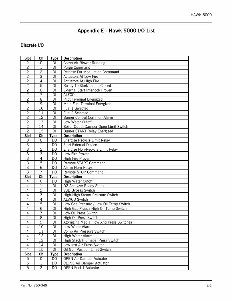
HAWK 5000
Appendix E - Hawk 5000 I/O List
Discrete I/O
Slot Ch Type Description2 0 DI Comb Air Blower Running2 1 DI Purge Command2 2 DI Release For Modulation Command2 3 DI Actuators At Low Fire2 4 DI Actuators At High Fire2 5 DI Ready To Start/ Limits Closed2 6 DI External Start Interlock Proven2 7 DI ALFCO2 8 DI Pilot Terminal Energized2 9 DI Main Fuel Terminal Energized2 10 DI Fuel 1 Selected2 11 DI Fuel 2 Selected2 12 DI Burner Control Common Alarm2 13 DI Low Water Cutoff2 14 DI Boiler Outlet Damper Open Limit Switch2 15 DI Burner START Relay Energized
Slot Ch Type Description3 0 DO Energize Recycle Limit Relay3 1 DO Start External Device3 2 DO Energize Non-Recycle Limit Relay3 3 DO Low Fire Proven3 4 DO High Fire Proven3 5 DO Remote START Command3 6 DO Alarm Horn Relay3 7 DO Remote STOP Command
Slot Ch Type Description4 0 DO High Water Cutoff4 1 DI O2 Analyzer Ready Status4 2 DI VSD Bypass Switch4 3 DI High-High Steam Pressure Switch4 4 DI ALWCO Switch4 5 DI Low Gas Pressure / Low Oil Temp Switch4 6 DI High Gas Press / High Oil Temp Switch4 7 DI Low Oil Press Switch4 8 DI High Oil Press Switch4 9 DI Atomizing Media Flow And Press Switches4 10 DI Low Water Alarm4 11 DI Comb Air Pressure Switch4 12 DI High Water Alarm4 13 DI High Stack (Furnace) Press Switch4 14 DI Low Inst Air Press Switch4 15 DI Oil Gun Position Limit Switch
Slot Ch Type Description5 0 DO OPEN Air Damper Actuator5 1 DO CLOSE Air Damper Actuator5 2 DO OPEN Fuel 1 Actuator
Part No. 750-349 E-1
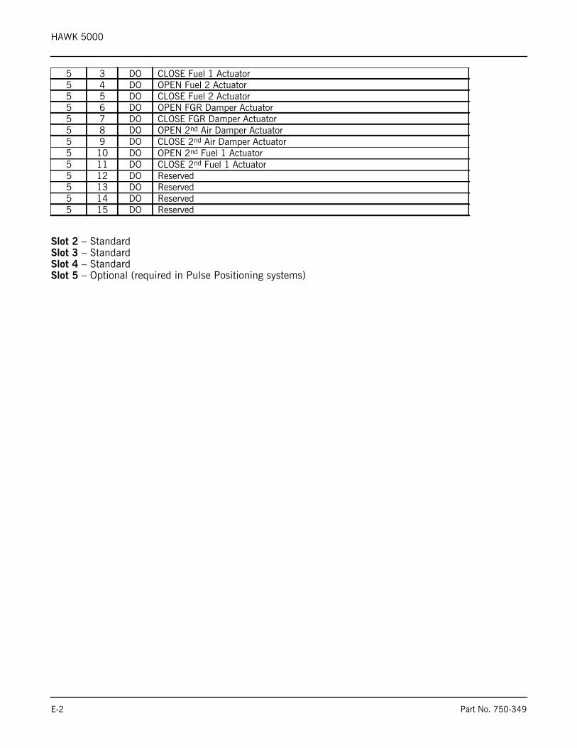
HAWK 5000
Slot 2 – StandardSlot 3 – StandardSlot 4 – StandardSlot 5 – Optional (required in Pulse Positioning systems)
5 3 DO CLOSE Fuel 1 Actuator5 4 DO OPEN Fuel 2 Actuator5 5 DO CLOSE Fuel 2 Actuator5 6 DO OPEN FGR Damper Actuator5 7 DO CLOSE FGR Damper Actuator5 8 DO OPEN 2nd Air Damper Actuator5 9 DO CLOSE 2nd Air Damper Actuator5 10 DO OPEN 2nd Fuel 1 Actuator5 11 DO CLOSE 2nd Fuel 1 Actuator5 12 DO Reserved5 13 DO Reserved5 14 DO Reserved5 15 DO Reserved
E-2 Part No. 750-349
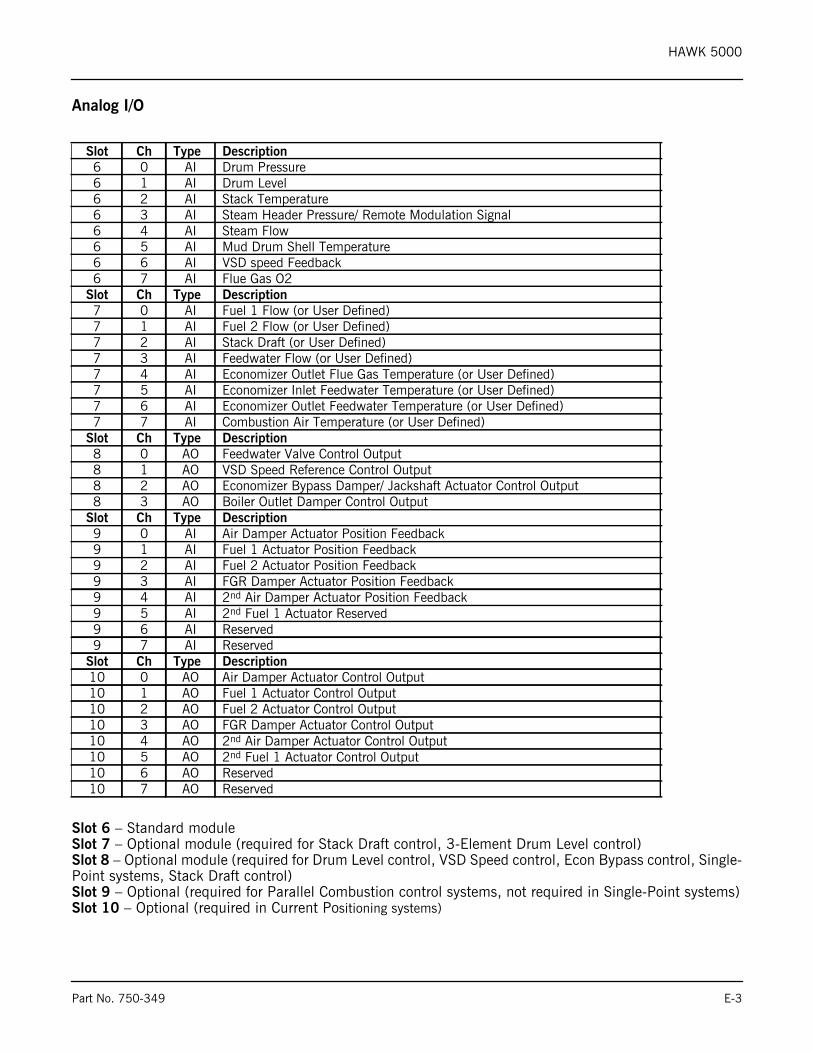
HAWK 5000
Analog I/O
Slot 6 – Standard moduleSlot 7 – Optional module (required for Stack Draft control, 3-Element Drum Level control) Slot 8 – Optional module (required for Drum Level control, VSD Speed control, Econ Bypass control, Single-Point systems, Stack Draft control)Slot 9 – Optional (required for Parallel Combustion control systems, not required in Single-Point systems)Slot 10 – Optional (required in Current Positioning systems)
Slot Ch Type Description6 0 AI Drum Pressure6 1 AI Drum Level6 2 AI Stack Temperature6 3 AI Steam Header Pressure/ Remote Modulation Signal6 4 AI Steam Flow6 5 AI Mud Drum Shell Temperature6 6 AI VSD speed Feedback6 7 AI Flue Gas O2
Slot Ch Type Description7 0 AI Fuel 1 Flow (or User Defined)7 1 AI Fuel 2 Flow (or User Defined)7 2 AI Stack Draft (or User Defined)7 3 AI Feedwater Flow (or User Defined)7 4 AI Economizer Outlet Flue Gas Temperature (or User Defined)7 5 AI Economizer Inlet Feedwater Temperature (or User Defined)7 6 AI Economizer Outlet Feedwater Temperature (or User Defined)7 7 AI Combustion Air Temperature (or User Defined)
Slot Ch Type Description8 0 AO Feedwater Valve Control Output8 1 AO VSD Speed Reference Control Output8 2 AO Economizer Bypass Damper/ Jackshaft Actuator Control Output8 3 AO Boiler Outlet Damper Control Output
Slot Ch Type Description9 0 AI Air Damper Actuator Position Feedback9 1 AI Fuel 1 Actuator Position Feedback9 2 AI Fuel 2 Actuator Position Feedback9 3 AI FGR Damper Actuator Position Feedback9 4 AI 2nd Air Damper Actuator Position Feedback9 5 AI 2nd Fuel 1 Actuator Reserved9 6 AI Reserved9 7 AI Reserved
Slot Ch Type Description10 0 AO Air Damper Actuator Control Output10 1 AO Fuel 1 Actuator Control Output10 2 AO Fuel 2 Actuator Control Output10 3 AO FGR Damper Actuator Control Output10 4 AO 2nd Air Damper Actuator Control Output10 5 AO 2nd Fuel 1 Actuator Control Output10 6 AO Reserved10 7 AO Reserved
Part No. 750-349 E-3

HAWK 5000
E-4 Part No. 750-349
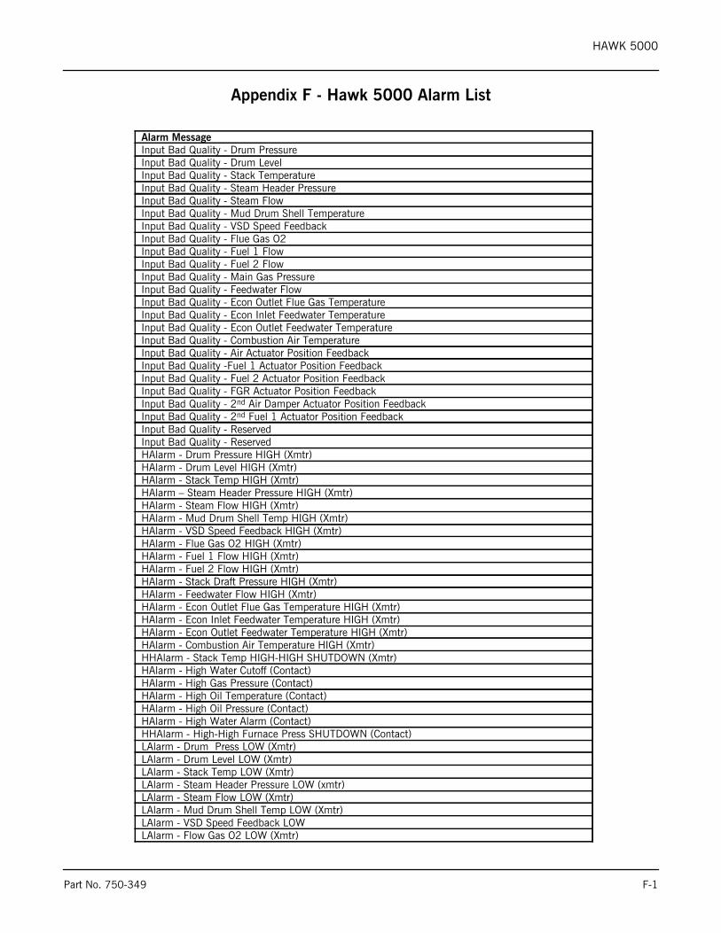
HAWK 5000
Appendix F - Hawk 5000 Alarm List
Alarm MessageInput Bad Quality - Drum PressureInput Bad Quality - Drum LevelInput Bad Quality - Stack TemperatureInput Bad Quality - Steam Header PressureInput Bad Quality - Steam FlowInput Bad Quality - Mud Drum Shell TemperatureInput Bad Quality - VSD Speed FeedbackInput Bad Quality - Flue Gas O2Input Bad Quality - Fuel 1 FlowInput Bad Quality - Fuel 2 FlowInput Bad Quality - Main Gas PressureInput Bad Quality - Feedwater FlowInput Bad Quality - Econ Outlet Flue Gas TemperatureInput Bad Quality - Econ Inlet Feedwater TemperatureInput Bad Quality - Econ Outlet Feedwater TemperatureInput Bad Quality - Combustion Air TemperatureInput Bad Quality - Air Actuator Position FeedbackInput Bad Quality -Fuel 1 Actuator Position FeedbackInput Bad Quality - Fuel 2 Actuator Position FeedbackInput Bad Quality - FGR Actuator Position FeedbackInput Bad Quality - 2nd Air Damper Actuator Position FeedbackInput Bad Quality - 2nd Fuel 1 Actuator Position FeedbackInput Bad Quality - ReservedInput Bad Quality - ReservedHAlarm - Drum Pressure HIGH (Xmtr)HAlarm - Drum Level HIGH (Xmtr)HAlarm - Stack Temp HIGH (Xmtr)HAlarm – Steam Header Pressure HIGH (Xmtr)HAlarm - Steam Flow HIGH (Xmtr)HAlarm - Mud Drum Shell Temp HIGH (Xmtr)HAlarm - VSD Speed Feedback HIGH (Xmtr)HAlarm - Flue Gas O2 HIGH (Xmtr)HAlarm - Fuel 1 Flow HIGH (Xmtr)HAlarm - Fuel 2 Flow HIGH (Xmtr)HAlarm - Stack Draft Pressure HIGH (Xmtr)HAlarm - Feedwater Flow HIGH (Xmtr)HAlarm - Econ Outlet Flue Gas Temperature HIGH (Xmtr)HAlarm - Econ Inlet Feedwater Temperature HIGH (Xmtr)HAlarm - Econ Outlet Feedwater Temperature HIGH (Xmtr)HAlarm - Combustion Air Temperature HIGH (Xmtr)HHAlarm - Stack Temp HIGH-HIGH SHUTDOWN (Xmtr)HAlarm - High Water Cutoff (Contact)HAlarm - High Gas Pressure (Contact)HAlarm - High Oil Temperature (Contact)HAlarm - High Oil Pressure (Contact)HAlarm - High Water Alarm (Contact)HHAlarm - High-High Furnace Press SHUTDOWN (Contact)LAlarm - Drum Press LOW (Xmtr)LAlarm - Drum Level LOW (Xmtr)LAlarm - Stack Temp LOW (Xmtr)LAlarm - Steam Header Pressure LOW (xmtr)LAlarm - Steam Flow LOW (Xmtr)LAlarm - Mud Drum Shell Temp LOW (Xmtr)LAlarm - VSD Speed Feedback LOWLAlarm - Flow Gas O2 LOW (Xmtr)
Part No. 750-349 F-1
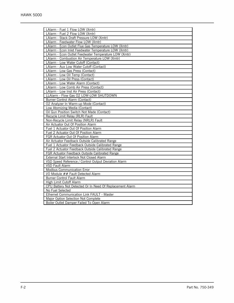
HAWK 5000
LAlarm - Fuel 1 Flow LOW (Xmtr)LAlarm - Fuel 2 Flow LOW (Xmtr)LAlarm - Stack Draft Pressure LOW (Xmtr)LAlarm - Feedwater Flow LOW (Xmtr)LAlarm - Econ Outlet Flue Gas Temperature LOW (Xmtr)LAlarm - Econ Inlet Feedwater Temperature LOW (Xmtr)LAlarm - Econ Outlet Feedwater Temperature LOW (Xmtr)LAlarm - Combustion Air Temperature LOW (Xmtr)LAlarm - Low Water Cutoff (Contact)LAlarm - Aux Low Water Cutoff (Contact)LAlarm - Low Gas Press (Contact)LAlarm - Low Oil Temp (Contact)LAlarm - Low Oil Press (Contact)LAlarm - Low Water Alarm (Contact)LAlarm - Low Comb Air Press (Contact)LAlarm - Low Inst Air Press (Contact)LLAlarm - Flow Gas O2 LOW-LOW SHUTDOWNBurner Control Alarm (Contact)O2 Analyzer In Warm-up Mode (Contact)Low Atomizing Media (Contact)Oil Gun Position Switch Not Made (Contact)Recycle Limit Relay (RLR) FaultNon-Recycle Limit Relay (NRLR) FaultAir Actuator Out Of Position AlarmFuel 1 Actuator Out Of Position AlarmFuel 2 Actuator Out Of Position AlarmFGR Actuator Out Of Position AlarmAir Actuator Feedback Outside Calibrated RangeFuel 1 Actuator Feedback Outside Calibrated RangeFuel 2 Actuator Feedback Outside Calibrated RangeFGR Actuator Feedback Outside Calibrated RangeExternal Start Interlock Not Closed AlarmVSD Speed Reference / Control Output Deviation AlarmVSD Fault AlarmModbus Communication ErrorI/O Module ## Fault Detected AlarmBurner Control Fault AlarmHigh Limit Cutoff AlarmCPU Battery Not Detected Or In Need Of Replacement AlarmNo Fuel SelectedEthernet Communication Link FAULT - MasterMajor Option Selection Not CompleteBoiler Outlet Damper Failed To Open Alarm
F-2 Part No. 750-349
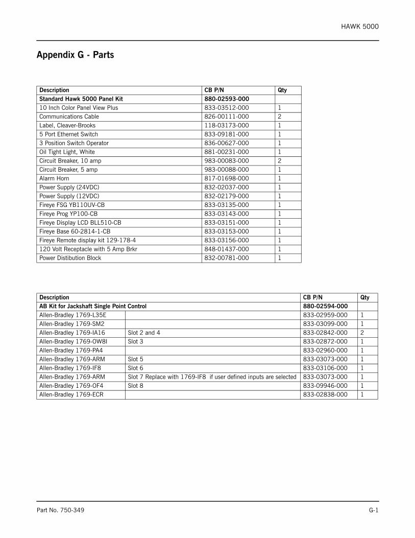
HAWK 5000
Appendix G - Parts
Description CB P/N QtyStandard Hawk 5000 Panel Kit 880-02593-00010 Inch Color Panel View Plus 833-03512-000 1Communications Cable 826-00111-000 2Label, Cleaver-Brooks 118-03173-000 15 Port Ethernet Switch 833-09181-000 13 Position Switch Operator 836-00627-000 1Oil Tight Light, White 881-00231-000 1Circuit Breaker, 10 amp 983-00083-000 2Circuit Breaker, 5 amp 983-00088-000 1Alarm Horn 817-01698-000 1Power Supply (24VDC) 832-02037-000 1Power Supply (12VDC) 832-02179-000 1Fireye FSG YB110UV-CB 833-03135-000 1Fireye Prog YP100-CB 833-03143-000 1Fireye Display LCD BLL510-CB 833-03151-000 1Fireye Base 60-2814-1-CB 833-03153-000 1Fireye Remote display kit 129-178-4 833-03156-000 1120 Volt Receptacle with 5 Amp Brkr 848-01437-000 1Power Distibution Block 832-00781-000 1
Description CB P/N QtyAB Kit for Jackshaft Single Point Control 880-02594-000Allen-Bradley 1769-L35E 833-02959-000 1Allen-Bradley 1769-SM2 833-03099-000 1Allen-Bradley 1769-IA16 Slot 2 and 4 833-02842-000 2Allen-Bradley 1769-OW8I Slot 3 833-02872-000 1Allen-Bradley 1769-PA4 833-02960-000 1Allen-Bradley 1769-ARM Slot 5 833-03073-000 1Allen-Bradley 1769-IF8 Slot 6 833-03106-000 1Allen-Bradley 1769-ARM Slot 7 Replace with 1769-IF8 if user defined inputs are selected 833-03073-000 1Allen-Bradley 1769-OF4 Slot 8 833-09946-000 1Allen-Bradley 1769-ECR 833-02838-000 1
Part No. 750-349 G-1
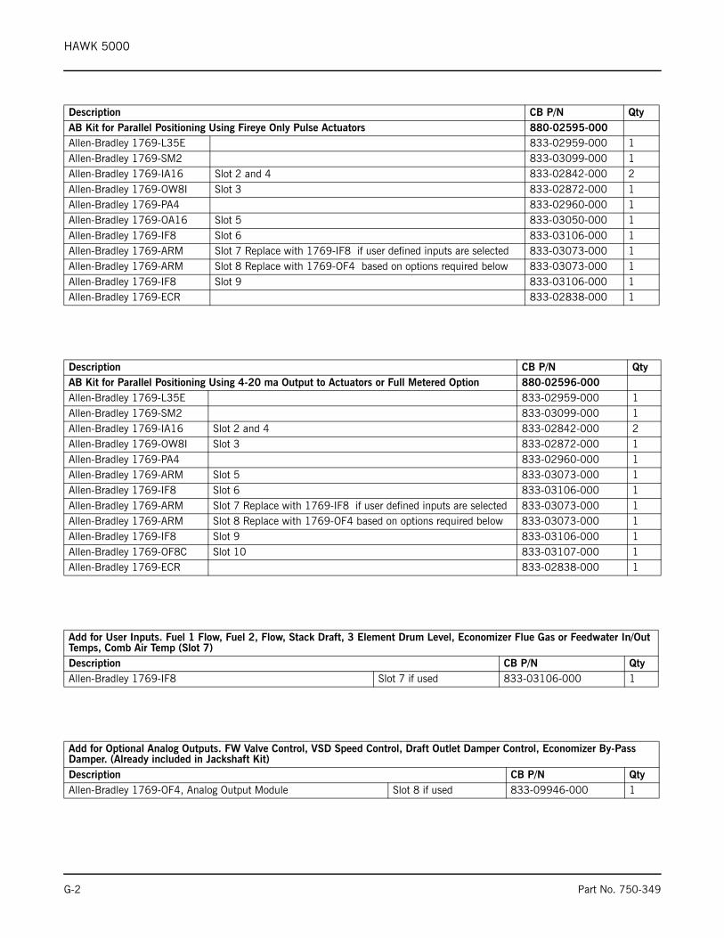
HAWK 5000
Description CB P/N QtyAB Kit for Parallel Positioning Using Fireye Only Pulse Actuators 880-02595-000Allen-Bradley 1769-L35E 833-02959-000 1Allen-Bradley 1769-SM2 833-03099-000 1Allen-Bradley 1769-IA16 Slot 2 and 4 833-02842-000 2Allen-Bradley 1769-OW8I Slot 3 833-02872-000 1Allen-Bradley 1769-PA4 833-02960-000 1Allen-Bradley 1769-OA16 Slot 5 833-03050-000 1Allen-Bradley 1769-IF8 Slot 6 833-03106-000 1Allen-Bradley 1769-ARM Slot 7 Replace with 1769-IF8 if user defined inputs are selected 833-03073-000 1Allen-Bradley 1769-ARM Slot 8 Replace with 1769-OF4 based on options required below 833-03073-000 1Allen-Bradley 1769-IF8 Slot 9 833-03106-000 1Allen-Bradley 1769-ECR 833-02838-000 1
Description CB P/N QtyAB Kit for Parallel Positioning Using 4-20 ma Output to Actuators or Full Metered Option 880-02596-000Allen-Bradley 1769-L35E 833-02959-000 1Allen-Bradley 1769-SM2 833-03099-000 1Allen-Bradley 1769-IA16 Slot 2 and 4 833-02842-000 2Allen-Bradley 1769-OW8I Slot 3 833-02872-000 1Allen-Bradley 1769-PA4 833-02960-000 1Allen-Bradley 1769-ARM Slot 5 833-03073-000 1Allen-Bradley 1769-IF8 Slot 6 833-03106-000 1Allen-Bradley 1769-ARM Slot 7 Replace with 1769-IF8 if user defined inputs are selected 833-03073-000 1Allen-Bradley 1769-ARM Slot 8 Replace with 1769-OF4 based on options required below 833-03073-000 1Allen-Bradley 1769-IF8 Slot 9 833-03106-000 1Allen-Bradley 1769-OF8C Slot 10 833-03107-000 1Allen-Bradley 1769-ECR 833-02838-000 1
Add for User Inputs. Fuel 1 Flow, Fuel 2, Flow, Stack Draft, 3 Element Drum Level, Economizer Flue Gas or Feedwater In/Out Temps, Comb Air Temp (Slot 7)Description CB P/N QtyAllen-Bradley 1769-IF8 Slot 7 if used 833-03106-000 1
Add for Optional Analog Outputs. FW Valve Control, VSD Speed Control, Draft Outlet Damper Control, Economizer By-Pass Damper. (Already included in Jackshaft Kit)Description CB P/N QtyAllen-Bradley 1769-OF4, Analog Output Module Slot 8 if used 833-09946-000 1
G-2 Part No. 750-349
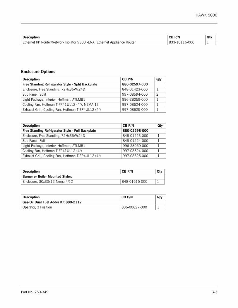
HAWK 5000
Enclosure Options
Description CB P/N QtyEthernet I/P Router/Network Isolator 9300 -ENA Ethernet Appliance Router 833-10116-000 1
Description CB P/N QtyFree Standing Refrigerator Style - Split Backplate 880-02597-000Enclosure, Free Standing, 72Hx36Wx24D 848-01423-000 1Sub Panel, Split 997-08594-000 2Light Package, Interior, Hoffman, ATLMB1 996-28059-000 1Cooling Fan, Hoffman T-FP41UL12 (4"), NEMA 12 997-08624-000 1Exhaust Grill, Cooling Fan, Hoffman T-EP4UL12 (4") 997-08625-000 1
Description CB P/N QtyFree Standing Refrigerator Style - Full Backplate 880-02598-000Enclosure, Free Standing, 72Hx36Wx24D 848-01423-000 1Sub Panel, Full 848-01424-000 1Light Package, Interior, Hoffman, ATLMB1 996-28059-000 1Cooling Fan, Hoffman T-FP41UL12 (4") 997-08624-000 1Exhaust Grill, Cooling Fan, Hoffman T-EP4UL12 (4") 997-08625-000 1
Description CB P/N QtyBurner or Boiler Mounted Style'sEnclosure, 30x30x12 Nema 4/12 848-01615-000 1
Description CB P/N QtyGas-Oil Dual Fuel Adder Kit 880-2112Operator, 3 Position 836-00627-000 1
Part No. 750-349 G-3
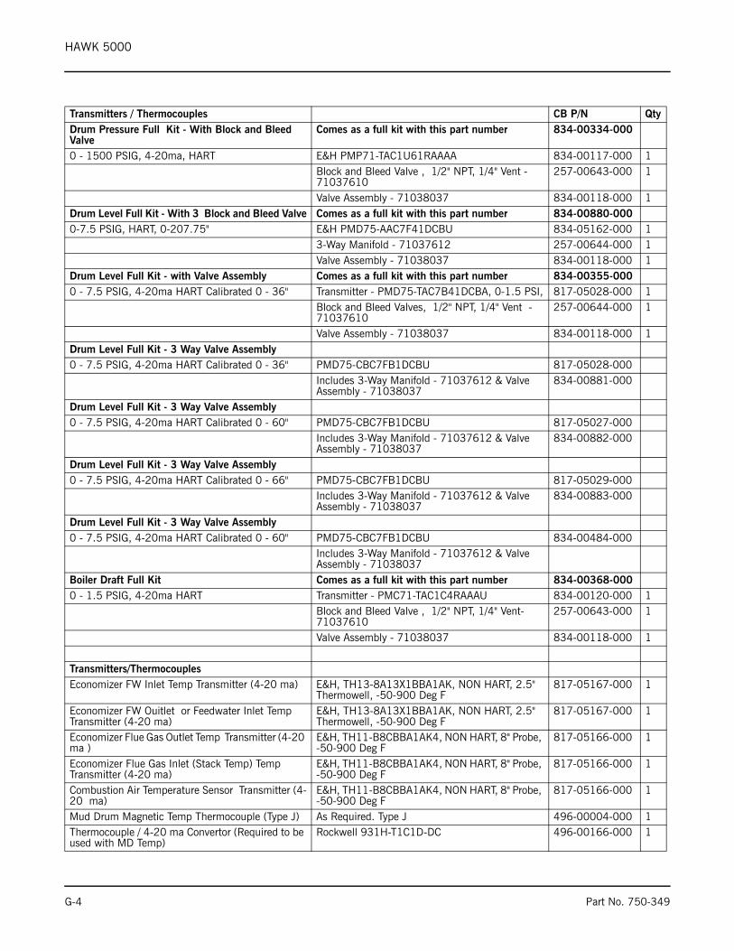
HAWK 5000
Transmitters / Thermocouples CB P/N QtyDrum Pressure Full Kit - With Block and Bleed Valve
Comes as a full kit with this part number 834-00334-000
0 - 1500 PSIG, 4-20ma, HART E&H PMP71-TAC1U61RAAAA 834-00117-000 1Block and Bleed Valve , 1/2" NPT, 1/4" Vent -71037610
257-00643-000 1
Valve Assembly - 71038037 834-00118-000 1Drum Level Full Kit - With 3 Block and Bleed Valve Comes as a full kit with this part number 834-00880-0000-7.5 PSIG, HART, 0-207.75" E&H PMD75-AAC7F41DCBU 834-05162-000 1
3-Way Manifold - 71037612 257-00644-000 1Valve Assembly - 71038037 834-00118-000 1
Drum Level Full Kit - with Valve Assembly Comes as a full kit with this part number 834-00355-0000 - 7.5 PSIG, 4-20ma HART Calibrated 0 - 36" Transmitter - PMD75-TAC7B41DCBA, 0-1.5 PSI, 817-05028-000 1
Block and Bleed Valves, 1/2" NPT, 1/4" Vent - 71037610
257-00644-000 1
Valve Assembly - 71038037 834-00118-000 1Drum Level Full Kit - 3 Way Valve Assembly0 - 7.5 PSIG, 4-20ma HART Calibrated 0 - 36" PMD75-CBC7FB1DCBU 817-05028-000
Includes 3-Way Manifold - 71037612 & Valve Assembly - 71038037
834-00881-000
Drum Level Full Kit - 3 Way Valve Assembly0 - 7.5 PSIG, 4-20ma HART Calibrated 0 - 60" PMD75-CBC7FB1DCBU 817-05027-000
Includes 3-Way Manifold - 71037612 & Valve Assembly - 71038037
834-00882-000
Drum Level Full Kit - 3 Way Valve Assembly0 - 7.5 PSIG, 4-20ma HART Calibrated 0 - 66" PMD75-CBC7FB1DCBU 817-05029-000
Includes 3-Way Manifold - 71037612 & Valve Assembly - 71038037
834-00883-000
Drum Level Full Kit - 3 Way Valve Assembly0 - 7.5 PSIG, 4-20ma HART Calibrated 0 - 60" PMD75-CBC7FB1DCBU 834-00484-000
Includes 3-Way Manifold - 71037612 & Valve Assembly - 71038037
Boiler Draft Full Kit Comes as a full kit with this part number 834-00368-0000 - 1.5 PSIG, 4-20ma HART Transmitter - PMC71-TAC1C4RAAAU 834-00120-000 1
Block and Bleed Valve , 1/2" NPT, 1/4" Vent- 71037610
257-00643-000 1
Valve Assembly - 71038037 834-00118-000 1
Transmitters/ThermocouplesEconomizer FW Inlet Temp Transmitter (4-20 ma) E&H, TH13-8A13X1BBA1AK, NON HART, 2.5"
Thermowell, -50-900 Deg F817-05167-000 1
Economizer FW Ouitlet or Feedwater Inlet Temp Transmitter (4-20 ma)
E&H, TH13-8A13X1BBA1AK, NON HART, 2.5" Thermowell, -50-900 Deg F
817-05167-000 1
Economizer Flue Gas Outlet Temp Transmitter (4-20 ma )
E&H, TH11-B8CBBA1AK4, NON HART, 8" Probe, -50-900 Deg F
817-05166-000 1
Economizer Flue Gas Inlet (Stack Temp) Temp Transmitter (4-20 ma)
E&H, TH11-B8CBBA1AK4, NON HART, 8" Probe, -50-900 Deg F
817-05166-000 1
Combustion Air Temperature Sensor Transmitter (4-20 ma)
E&H, TH11-B8CBBA1AK4, NON HART, 8" Probe, -50-900 Deg F
817-05166-000 1
Mud Drum Magnetic Temp Thermocouple (Type J) As Required. Type J 496-00004-000 1Thermocouple / 4-20 ma Convertor (Required to be used with MD Temp)
Rockwell 931H-T1C1D-DC 496-00166-000 1
G-4 Part No. 750-349
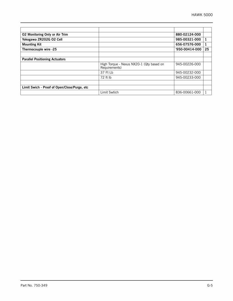
HAWK 5000
O2 Monitoring Only or Air Trim 880-02124-000Yokogawa ZR202G O2 Cell 985-00321-000 1Mounting Kit 656-07576-000 1Thermocouple wire -25 '950-00414-000 25
Parallel Positioning ActuatorsHigh Torque - Nexus NX20-1 (Qty based on Requirements)
945-00226-000
37 Ft Lb 945-00232-00072 ft lb 945-00233-000
Limit Swich - Proof of Open/Close/Purge, etcLimit Swtich 836-00661-000 1
Part No. 750-349 G-5

e-mail: [email protected] Address: http://www.cleaverbrooks.com