HAWE product range – Contentsdownloads.hawe.com/k/k177-en.pdf · HAWE product range – Contents...
299
HAWE Products Our current product range
Transcript of HAWE product range – Contentsdownloads.hawe.com/k/k177-en.pdf · HAWE product range – Contents...
HAWE Products Our current product range

HAWE product range – Contents
2/299 HAWE Products - 04-2017-5.1 © HAWE Hydraulik SE
1 Pumps 8
1.1 Hydraulic pumps 8
1.2 Hydraulic Unit 36
2 Valves 64
2.1 Directional spool valves 64
2.2 Directional seated valves 104
2.3 Pressure control valves 158
2.4 Flow valves 202
2.5 Check valves 228
3 Hydraulic cylinders and hydraulicmotors 250
Hydraulic clamps type HSE and HSA 252
Axial piston motor type M60N 254
4 Hydraulic accessories 256
Diaphragm accumulator type AC 258
Piston type accumulator type HPS 260
Pressure switch type DG, electronic pressuretransducer type DT 262
Pressure lter type PFM 264
Fittings 266
Compact hydraulic power packs type KA and KAW
Proportional directional spool valves type PSL and PSV
Hydraulic clamps type HSE and HSA
Pressure switches type DG and analogous electronic pressure transducers
Programmable logic valve controlstype PLVC

© HAWE Hydraulik SE HAWE Products - 04-2017-5.1 3/299
5 Electronics 268
Line connector with economy circuit type MSD andothers 270
Proportional amplifier type EV 272
Proportional amplifier type EV2S 274
Programmable logic valve control type PLVC, CAN-IO 276
6 Appendix 278
Hydraulic uids – notes for selection 278
Formulas and units 285
Contact ofces and representatives 290
Headquarters
HAWE Hydraulik SE
Streitfeldstr. 25
81673 München, Germany
Postfach 800804 81608 München, Germany
Tel. +49 89 37 91 00 - 1000
Fax: +49 89 37 91 00 - 9 1000
e-mail: [email protected]
www.hawe.com
4/299 HAWE Products - 04-2017-5.1 © HAWE Hydraulik SE
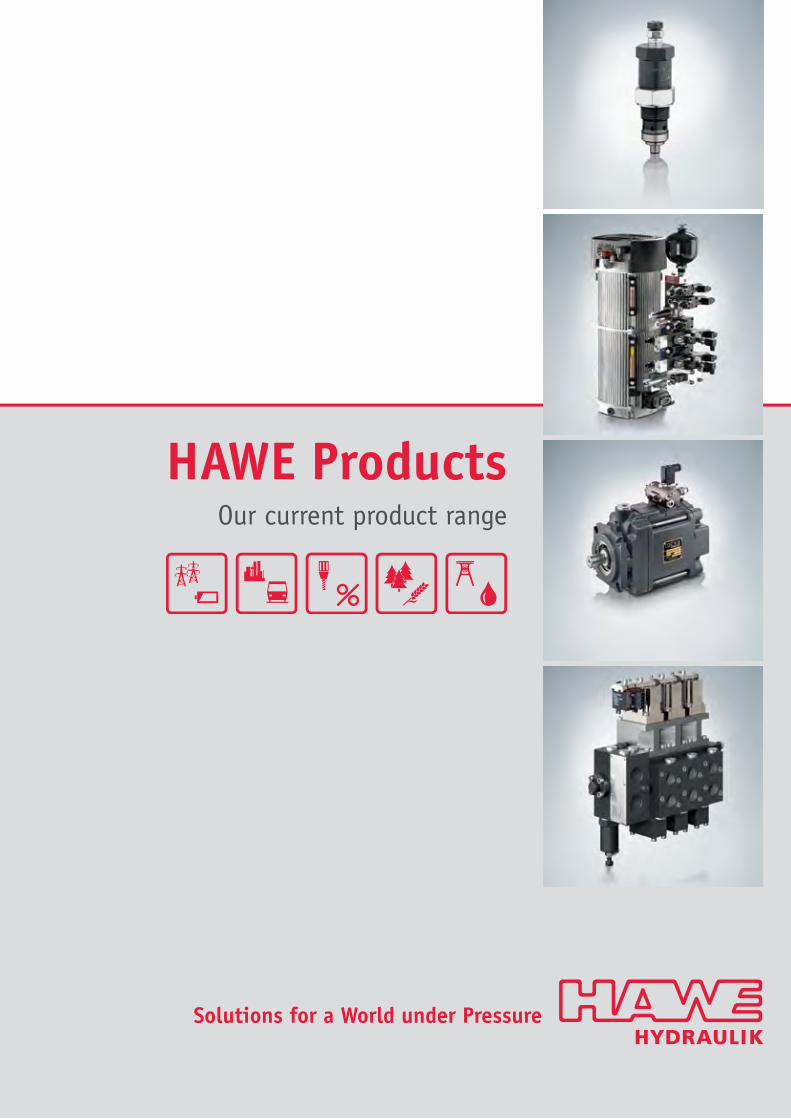
HAWE Hydraulik produces and develops hydraulic components and solutions for many sectors of the mechanical engineering and plant engineering
industries. HAWE also helps to resolve global problems regarding energy, infrastructure, efcient production, nutrition and resources.
View of the Alps from the HAWE plant in Kaufbeuren, Germany
With over 65 years’ experience and a focus on constantly incorporating new technologies, HAWE is a responsible partner for you when it comes to
conserving resources, reducing costs, making machinery safer and developing innovative ideas.
The product range includes constant and variable pumps, hydraulic power packs, valves, sensors and accessories. The modular system is
complemented by electronic components which are perfectly coordinated with the hydraulic components and simplify control, signal evaluation
and fault detection. All pressurised parts are made from steel, which allows for pressures of up to 700 bar and guarantees that components are
durable, safe and compact in mid-pressure ranges.
As a result, HAWE Hydraulik products offer concrete benets for manufacturers and their customers thanks to the consistent modular design which
has been tailored to solutions for a world under pressure. “Solutions for a World under Pressure”

Introduction
© HAWE Hydraulik SE HAWE Products - 04-2017-5.1 5/299
Information about this compact product catalogue
This compact catalogue is structured according to nomenclature and offers an initial overview of the available components and their performancedata. Thanks to our approach of consistently designing all components based on a modular system, our components can be easily combined toform space-saving units offering added value.If your requirements are not covered by the product range shown here, we will also be glad to design bespoke hydraulic solutions.Your HAWE sales representative or sales partner can provide additional technical documentation, drawings or 3D models for individualcomponents and even complete solutions. They will be glad to assist you with selecting and configuring your system, commissioning and service.The contact data for the contact partner in your region is attached and can also be found at HAWE Hydraulik SE - Global Website.
Compactoil immersed hydraulic power packswith valve mounting
Axial piston pumpswith high power density
Zero-leakage seated valvesup to 700 bar
Directional spool valvesmodular and flexible

6/299 HAWE Products - 04-2017-5.1 © HAWE Hydraulik SE
HAWE - Intelligent solutions to tackle global problems
Stationary hydraulics
In machine tools, testing machinery and many other industrial applications, tensioning and clamping functions are often actuated using
hydraulics. In addition to the high output density and energy-efcient drive concept, the integrated monitoring functions also prove particularly
useful during operation.
Compact hydraulic power packs in standby mode, a speed-controlled drive concept and an accumulator charging mode are just some of the
methods used to increase system efficiency. What's more, zero-leakage directional seated valves, high pressure and intelligent control by the
electronics system open up other application elds such as hydraulic tools and renewable energy.
Introduction
© HAWE Hydraulik SE HAWE Products - 04-2017-5.1 7/299
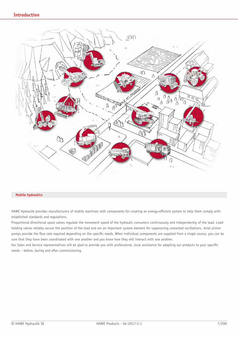
Mobile hydraulics
HAWE Hydraulik provides manufacturers of mobile machines with components for creating an energy-efcient system to help them comply with
established standards and regulations.
Proportional directional spool valves regulate the movement speed of the hydraulic consumers continuously and independently of the load. Load-
holding valves reliably secure the position of the load and are an important system element for suppressing unwanted oscillations. Axial piston
pumps provide the ow rate required depending on the specic needs. When individual components are supplied from a single source, you can be
sure that they have been coordinated with one another and you know how they will interact with one another.
Our Sales and Service representatives will be glad to provide you with professional, local assistance for adapting our products to your specic
needs – before, during and after commissioning.

Pumps
8/299 HAWE Products - 04-2017-5.1 © HAWE Hydraulik SE
1.1 Hydraulic pumps
Radial piston pump type R, RG and RZ 12
Variable displacement axial piston pump type V30E 16
Variable displacement axial piston pump type V30D 20
Variable displacement axial piston pump type V80M 24
Variable displacement axial piston pump type V60N 26
Variable displacement axial piston pump type K60N 30
Air-driven hydraulic pump type LP 32
Hand pump type H, HE and HD 34
Radial piston pump type R and RG
Variable displacement axial piston pump
type V60N
© HAWE Hydraulik SE HAWE Products - 04-2017-5.1 9/299
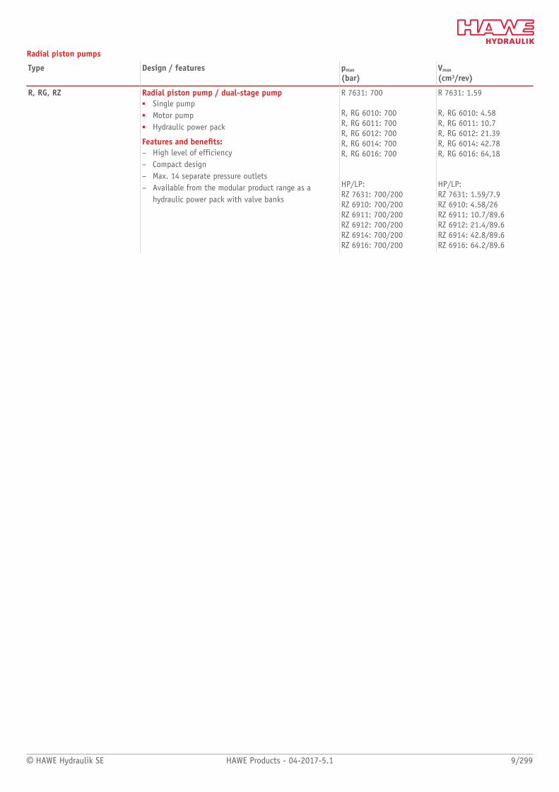
Radial piston pumps
Type Design / features pmax
(bar)Vmax
(cm3/rev)
R, RG, RZ Radial piston pump / dual-stage pump■ Single pump■ Motor pump■ Hydraulic power pack
Features and benets:– High level of efficiency– Compact design– Max. 14 separate pressure outlets– Available from the modular product range as a
hydraulic power pack with valve banks
R 7631: 700
R, RG 6010: 700R, RG 6011: 700R, RG 6012: 700R, RG 6014: 700R, RG 6016: 700
HP/LP:RZ 7631: 700/200RZ 6910: 700/200RZ 6911: 700/200RZ 6912: 700/200RZ 6914: 700/200RZ 6916: 700/200
R 7631: 1.59
R, RG 6010: 4.58R, RG 6011: 10.7R, RG 6012: 21.39R, RG 6014: 42.78R, RG 6016: 64,18
HP/LP:RZ 7631: 1.59/7.9RZ 6910: 4.58/26RZ 6911: 10.7/89.6RZ 6912: 21.4/89.6RZ 6914: 42.8/89.6RZ 6916: 64.2/89.6
10/299 HAWE Products - 04-2017-5.1 © HAWE Hydraulik SE
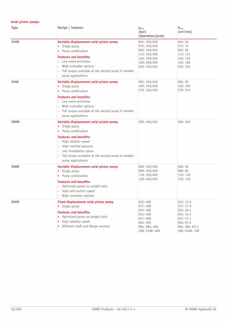
Axial piston pumps
Type Design / features pmax
(bar)(Operation/peak)
Vmax
(cm3/rev)
V30D Variable displacement axial piston pump■ Single pump■ Pump combination
Features and benets:– Low-noise emissions– Wide controller options– Full torque available at the second pump in tandem
pump applications
045: 350/420075: 350/420095: 350/420115: 250/300140: 350/420160: 250/300250: 350/420
045: 45075: 75095: 95115: 115140: 140160: 160250: 250
V30E Variable displacement axial piston pump■ Single pump■ Pump combination
Features and benets:– Low noise emissions– Wide controller options– Full torque available at the second pump in tandem
pump applications
095: 350/420160: 350/420270: 350/420
095: 95160: 160270: 270
V80M Variable displacement axial piston pump■ Single pump■ Pump combination
Features and benets:– High rotation speed– High nominal pressure– Less installation space– Full torque available at the second pump in tandem
pump applications
200: 400/450 200: 202
V60N Variable displacement axial piston pump■ Single pump■ Pump combination
Features and benets:– Optimized power-to-weight ratio– High self-suction speed– Wide controller options
060: 350/400090: 350/400110: 350/400130: 400/450
060: 60090: 90110: 110130: 130
K60N Fixed displacement axial piston pump■ Single pump
Features and benets:■ Optimized power-to-weight ratio■ High rotation speed■ Different shaft and ange versions
012: 400017: 400025: 400034: 400047: 400064: 400084, 984: 400108, 9108: 400
012: 12.6017: 17.0025: 25.4034: 34.2047: 47.1064: 63.5084, 984: 83.5108, 9108: 108
© HAWE Hydraulik SE HAWE Products - 04-2017-5.1 11/299
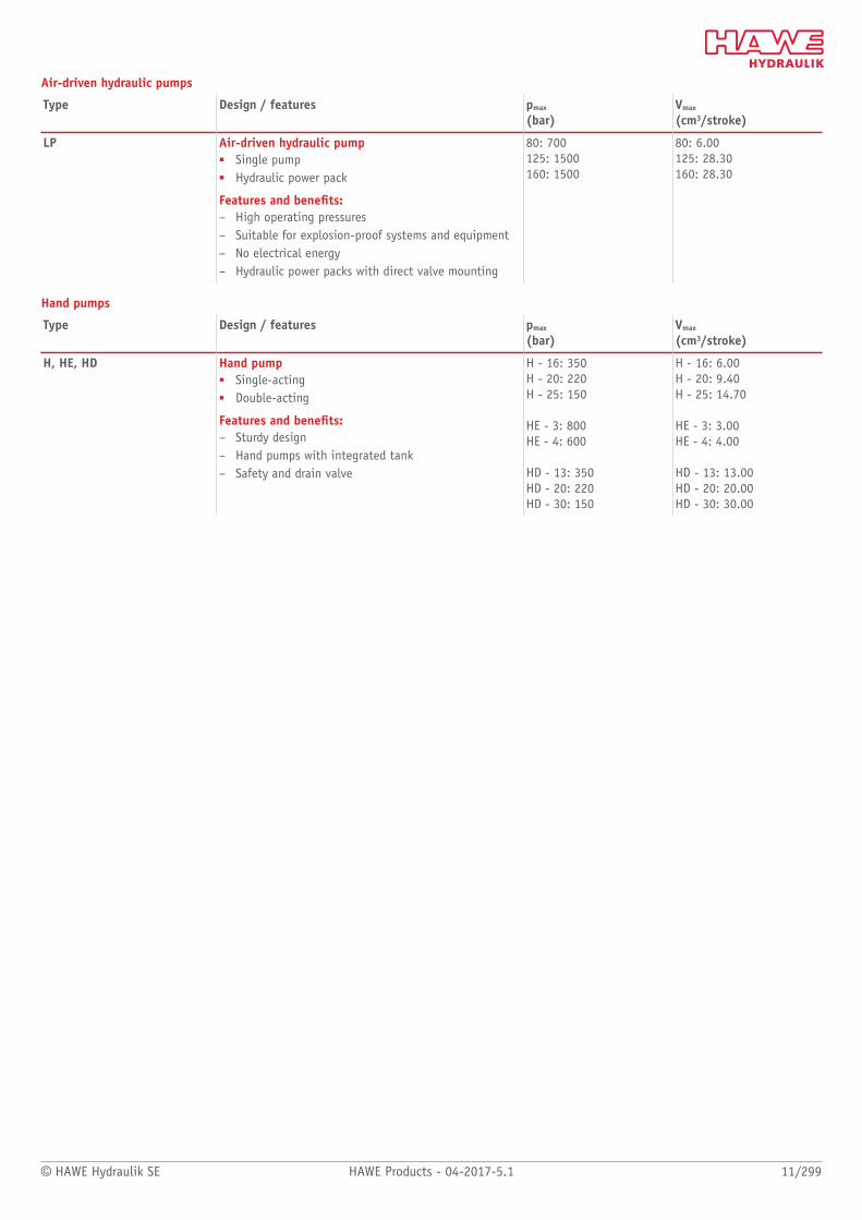
Air-driven hydraulic pumps
Type Design / features pmax
(bar)Vmax
(cm3/stroke)
LP Air-driven hydraulic pump■ Single pump■ Hydraulic power pack
Features and benets:– High operating pressures– Suitable for explosion-proof systems and equipment– No electrical energy– Hydraulic power packs with direct valve mounting
80: 700125: 1500160: 1500
80: 6.00125: 28.30160: 28.30
Hand pumps
Type Design / features pmax
(bar)Vmax
(cm3/stroke)
H, HE, HD Hand pump■ Single-acting■ Double-acting
Features and benets:– Sturdy design– Hand pumps with integrated tank– Safety and drain valve
H - 16: 350H - 20: 220H - 25: 150
HE - 3: 800HE - 4: 600
HD - 13: 350HD - 20: 220HD - 30: 150
H - 16: 6.00H - 20: 9.40H - 25: 14.70
HE - 3: 3.00HE - 4: 4.00
HD - 13: 13.00HD - 20: 20.00HD - 30: 30.00

Individual pumps
12/299 HAWE Products - 04-2017-5.1 © HAWE Hydraulik SE
1.1 Radial piston pump type R, RG and RZ
Radial piston pumps are a type of hydraulic pump. They consist of valve-controlled pump
cylinders that are arranged radially.
The radial piston pump type R, RG and RZ has a closed pump housing. Therefore, besides
use as a motor pump outside an oil tank, installation in the container of a hydraulic power
pack is also possible. The radial piston pump is available with several pressure outlets
which enable the same or several different volumetric ows. Type RZ is a classic dual-stage
pump consisting of a radial piston pump and a gear pump. The radial piston pump type RG
has plain bearings which have a longer storage life. This type is therefore used in extreme
operating conditions.
Extremely high volumetric ows can be achieved by arranging up to 6 radials in parallel.
When the radial piston pump is used in the hydraulic power pack, it is suitable for use as a
highly compact control system. Connection blocks and valve banks can be mounted on the
cover plate of the hydraulic power packs.
Features and benets:■ High level of efficiency■ Compact design■ Max. 14 separate pressure outlets■ Available from the modular product range as a hydraulic power pack with valve banks
Intended applications:■ Press construction■ Jig construction■ Testing and laboratory devices■ Lubricating systems
Nomen-clature:
Radial piston pump
Design: Single pump ; dual-stage pump
pmax: 700 bar
Qmax: 91.2 l/min
Vg: 64.18 cm³/rev
Design and order coding example
RZ 0,9 / 2 - 16
Sizes Delivery ow gear pump [lpm]
Basic type, delivery ow [lpm] ■ Type R (version with roller bearing)■ Type RG (version with plain bearing)■ Type RZ (dual-stage pump)
Additional versions:■ With several pressure ports■ With separate ports for the ow of one or two pump elements (Qmax = 4,4 lpm)
e.g. as control oil supply

© HAWE Hydraulik SE HAWE Products - 04-2017-5.1 13/299
Function
Single pump type R and RG Single pump type RZonly high-pressure section, low-pressure section is installed by customer
Single pump type RZHigh and low-pressure section
Pump with several pressure outlets (example for an Singlepump)
General parameters and dimensions
Single pump type R and RG
Single pump type RZ
14/299 HAWE Products - 04-2017-5.1 © HAWE Hydraulik SE
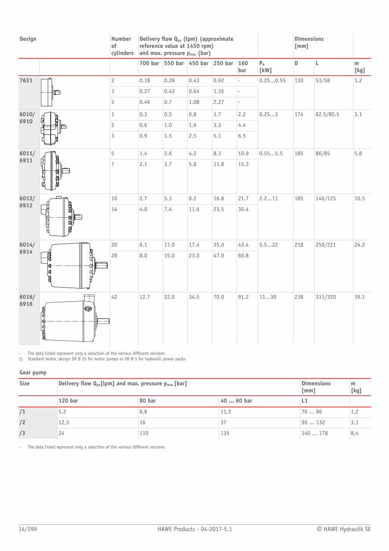
Design Numberofcylinders
Delivery ow Qpu (lpm) (approximatereference value at 1450 rpm) and max. pressure pmax (bar)
Dimensions[mm]
700 bar 550 bar 450 bar 250 bar 160bar
PN
[kW]D L m
[kg]
2 0.18 0.28 0.43 0.92 -
3 0.27 0.42 0.64 1.35 -
7631
5 0.46 0.7 1.08 2.27 -
0.25...0.55 130 53/58 3.2
1 0.3 0.5 0.8 1.7 2.2
2 0.6 1.0 1.6 3.3 4.4
6010/6910
3 0.9 1.5 2.5 5.1 6.5
0.25...3 174 82.5/85.5 3.1
5 1.4 2.6 4.2 8.3 10.96011/6911
7 2.1 3.7 5.8 11.8 15.3
0.55...5.5 185 86/85 5.8
10 2.7 5.3 8.2 16.8 21.76012/6912
14 4.0 7.4 11.6 23.5 30.4
2.2...11 185 146/125 10.5
20 6.1 11.0 17.4 35.0 43.46014/6914
28 8.0 15.0 23.0 47.0 60.8
5.5...22 218 250/221 24.2
6016/6916
42 12.7 22.0 34.5 70.0 91.2 11...30 238 311/320 39.1
- The data listed represent only a selection of the various different versions1) Standard motor, design IM B 35 for motor pumps or IM B 5 for hydraulic power packs
Gear pump
Size Delivery ow Qpu[lpm] and max. pressure pmax [bar] Dimensions [mm]
m[kg]
120 bar 80 bar 40 ... 60 bar L1
/1 5,2 8,8 11,3 70 ... 86 1,2
/2 12,3 16 37 96 ... 132 3,1
/3 24 110 135 140 ... 178 8,4
- The data listed represent only a selection of the various different versions
© HAWE Hydraulik SE HAWE Products - 04-2017-5.1 15/299
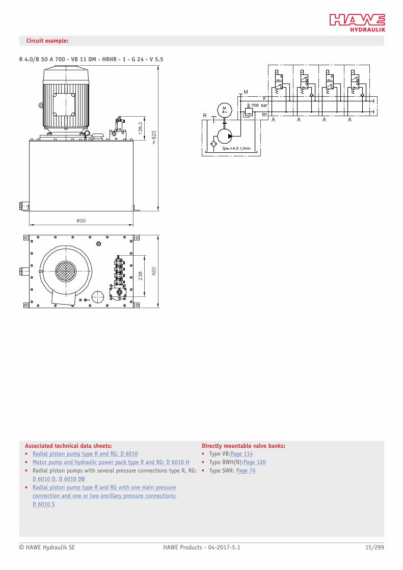
Associated technical data sheets:■ Radial piston pump type R and RG: D 6010■ Motor pump and hydraulic power pack type R and RG: D 6010 H■ Radial piston pumps with several pressure connections type R, RG:
D 6010 D, D 6010 DB■ Radial piston pump type R and RG with one main pressure
connection and one or two ancillary pressure connections:D 6010 S
Directly mountable valve banks:■ Type VB:Page 114■ Type BWH(N):Page 120■ Type SWR: Page 76
Circuit example:
R 4.0/B 50 A 700 - VB 11 DM - HRHR - 1 - G 24 - V 5.5

Individual pumps
16/299 HAWE Products - 04-2017-5.1 © HAWE Hydraulik SE
1.1 Variable displacement axial piston pump type V30E
Variable displacement axial piston pumps operate according to the bent axis principle. They
adjust the geometric output volume from maximum to zero. As a result they vary the ow
rate that is provided to the loads.
The axial piston pump type V30E is designed for open circuits in mobile hydraulics and
operate according to the swash plate principle. They are available with the option of a
thru-shaft for operating additional hydraulic pumps in series.
The sturdy pump is particularly suitable for continuous operation in challenging applica-
tions. The range of pump controllers allows the axial piston pump to be used in a variety of
applications.
Features and benets:■ Low noise emissions■ Wide controller options■ Full torque available at the second pump in tandem pump applications
Intended applications:■ Machines for forestry and agricultural purposes■ Cranes and lifting equipment■ Construction machines
Nomen-clature:
Axial piston pumpVariable pump
Design: Single pump Multiple pump
pmax: System pressure: 350 barPeak pressure: 420 bar
Vg max : 270 cm³/rev
Design and order coding example
V30E - 095 R S F N - 1 - 2 - XX /LSP /120 - 200
Pressure specification [bar]
Torque setting [Nm]
Controllers See section "Controller"
Release
swash plate angle indicator With/without swash plate angle indicator
Housing version With/without thru-shaft
Seal material ■ NBR (N)■ EPDM (E)■ FKM (V, C)
Flange version ■ Flange ISO 3019-2 (G)■ Flange SAE J744 (F, W)
Shaft version ■ Spline shaft DIN 5480 (D)■ Parallel key (K)■ Spline shaft SAE J744 (S, U)
Rotating direction Anti-clockwise (L), clockwise (R)
Nominal size
Basic type

© HAWE Hydraulik SE HAWE Products - 04-2017-5.1 17/299
Function
Single pump Multiple pump
Controller
Pressure controller:■ Pressure controller (P, Pb)■ Electro-proportional pressure controller (P-PMVPS)
Flow controller■ Load-sensing controller with integrated pressure limitation (LSP, LSPb)■ Load-sensing controller with integrated pressure limitation and electric pump direction switching (LSP-BVPM)■ Electro-hydraulic ow controller with integrated pivoting angle pick-up and control electronics for adjustment of setpoint and actual value
(EM.CH)
Power controller:■ Power controller (L)■ Power controller (Lf, Lf1)

18/299 HAWE Products - 04-2017-5.1 © HAWE Hydraulik SE
General parameters and dimensions
Drain port Suction port
Pressure port
(connection locations for clockwise operation)
1 Drain port
2 Suction port
3 Pressure connection
Parameters
Geom. delivery volume
Nominal pressure
Max.rotationspeed
Dimensions [mm] approx.
m[kg]
Vg
[cm³/rev]pnom (pmax)[bar]
n[rpm]
L L1 H H1 B (with controller)
V30E - 095 95 2500 296 75 236 36 190 57
V30E - 160 160 2100 332 75 273 36 212 77
V30E - 270 270
350 (420)
1800 399 88 326 36 266 129
Ports
Pressure connection Suction port Drain port
V30E - 095 1 1/4" SAE J518 2 1/2" SAE J518 G 3/4
V30E - 160 1 1/4" SAE J518 2 1/2" SAE J518 G 3/4
V30E - 270 1 1/2" SAE J518 3" SAE J518 G 1
© HAWE Hydraulik SE HAWE Products - 04-2017-5.1 19/299
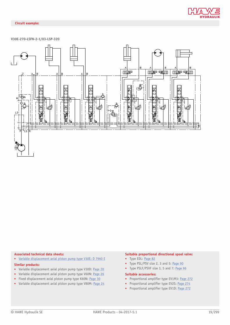
Associated technical data sheets:■ Variable displacement axial piston pump type V30E: D 7960 E
Similar products:■ Variable displacement axial piston pump type V30D: Page 20■ Variable displacement axial piston pump type V60N: Page 26■ Fixed displacement axial piston pump type K60N: Page 30■ Variable displacement axial piston pump type V80M: Page 24
Suitable proportional directional spool valve:■ Type EDL: Page 82■ Type PSL/PSV size 2, 3 and 5: Page 90■ Type PSLF/PSVF size 3, 5 and 7: Page 96
Suitable accessories:■ Proportional amplifier type EV1M3: Page 272■ Proportional amplifier type EV2S: Page 274■ Proportional amplifier type EV1D: Page 272
Circuit example:
V30E-270-LSFN-2-1/03-LSP-320

Individual pumps
20/299 HAWE Products - 04-2017-5.1 © HAWE Hydraulik SE
1.1 Variable displacement axial piston pump type V30D
Variable displacement axial piston pumps operate according to the bent axis principle. They
adjust the geometric output volume from maximum to zero. As a result they vary the ow
rate that is provided to the loads.
The axial piston pump type V30D is designed for open circuits in industrial hydraulics and
operate according to the swash plate principle. They are available with the option of a
thru-shaft for operating additional hydraulic pumps in series.
The sturdy pump is particularly suitable for continuous operation in challenging applica-
tions. The range of pump controllers allows the axial piston pump to be used in a variety of
applications.
Features and benets:■ Low-noise emissions■ Wide controller options■ Full torque available at the second pump in tandem pump applications
Intended applications:■ Presses■ Industrial plants■ Marine cranes and winches■ Power pack assembly
Nomen-clature:
Axial piston pumpVariable pump
Design: Single pump Multiple pump
pmax: System pressure: 350 barPeak pressure: 420 bar
Vg max : 250 cm³/rev
Design and order coding example
V30D - 095 R SF N - 1 - 1 - XX /LN -2 /120 - 200
Pressure specification [bar]
Torque setting [Nm]
Additional versions e.g. stroke limitation
Controller See section "Controller"
Release
swash plate angle indicator With/without swash plate angle indicator
Housing version With/without thru-shaft
Seal material ■ NBR (N)■ EPDM (E)■ FKM (V)
Shaft version/ange version ■ Spline shaft DIN 5480 (D)■ Spline shaft SAE J744 (S)■ Parallel key (K)
Rotating direction Anti-clockwise (L), clockwise (R)
Nominal size
Basic type
© HAWE Hydraulik SE HAWE Products - 04-2017-5.1 21/299
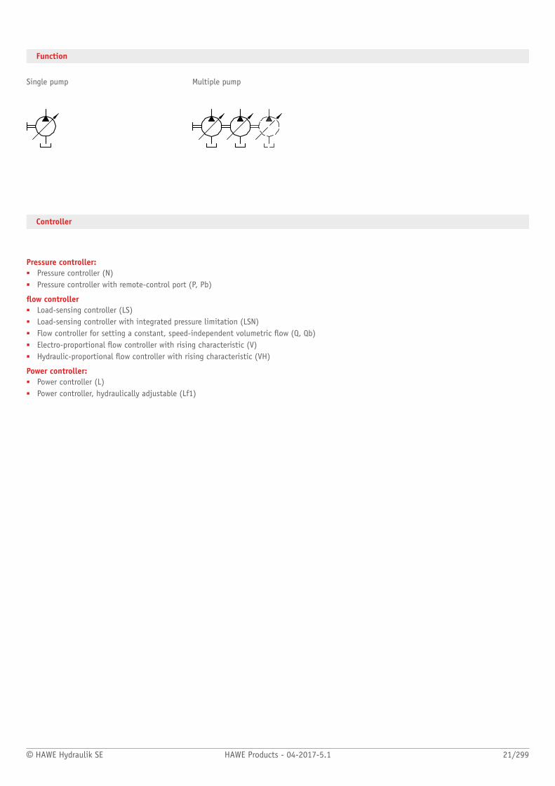
Function
Single pump Multiple pump
Controller
Pressure controller:■ Pressure controller (N)■ Pressure controller with remote-control port (P, Pb)
ow controller■ Load-sensing controller (LS)■ Load-sensing controller with integrated pressure limitation (LSN)■ Flow controller for setting a constant, speed-independent volumetric ow (Q, Qb)■ Electro-proportional ow controller with rising characteristic (V)■ Hydraulic-proportional ow controller with rising characteristic (VH)
Power controller:■ Power controller (L)■ Power controller, hydraulically adjustable (Lf1)

22/299 HAWE Products - 04-2017-5.1 © HAWE Hydraulik SE
General parameters and dimensions
Drain port Suction port
Pressure port
(connection locations for clockwise operation)
1 Drain port
2 Suction port
3 Pressure connection
Parameters
Geom. delivery volume
Nominal pressure
Max rotationspeed
Dimensions [mm]
m[kg]
Vg
[cm³/rev]pnom (pmax)[bar]
n[rpm]
L L1 H H1 B (with controller)
V30D - 045 45 2600 268 68 150 82 160 40 (46)
V30D - 075 75 2400 310 80 170 86 178 60 (66)
V30D - 095 95
350 (420)
2200 341 93 196 87 196 70 (76)
V30D - 115 115 250 (300)1) 2000 341 93 196 87 196 70 (76)
V30D - 140 140 350 (420) 2200 363 90 212 85 212 85 (91)
V30D - 160 160 250 (300)1) 1900 363 90 212 85 212 85 (91)
V30D - 250 265 350 (420) 1800 432 115 224 97 272 130 (136)
1) Higher pressures are possible with reduced delivery ow
Ports
Pressure connection Suction port Drain port
V30D - 045 3/4" SAE J518 1 1/2" SAE J518 G 1/2
V30D - 075 1" SAE J518 2" SAE J518 G 3/4
V30D - 095 1 1/4" SAE J518 2" SAE J518 G 3/4
V30D - 115 1 1/4" SAE J518 2" SAE J518 G 3/4
V30D - 140 1 1/4" SAE J518 2 1/2" SAE J518 G 3/4
V30D - 160 1 1/4" SAE J518 2 1/2" SAE J518 G 3/4
V30D - 250 1 1/2" SAE J518 3" SAE J518 M 33x 2

© HAWE Hydraulik SE HAWE Products - 04-2017-5.1 23/299
Associated technical data sheets:■ Variable displacement axial piston pump type V30D: D 7960,
Similar products:■ Variable displacement axial piston pump type V30E: Page 16■ Variable displacement axial piston pump type V60N: Page 26■ Fixed displacement axial piston pump type K60N: Page 30■ Variable displacement axial piston pump type V80M: Page 24
Suitable proportional directional spool valve:■ Type EDL: Page 82■ Type PSL/PSV 2, 3 and 5: Page 90■ Type PSLF/PSVF 3, 5 and 7: Page 96
Suitable accessories:■ Proportional amplifier type EV1M3: Page 272■ Proportional amplifier type EV2S: Page 274■ Proportional amplifier type EV1D: Page 272
Circuit example:
V30D-250-LSN-2-1/05-LSN-320

Individual pumps
24/299 HAWE Products - 04-2017-5.1 © HAWE Hydraulik SE
1.1 Variable displacement axial piston pump type V80M
Variable displacement axial piston pumps operate according to the bent axis principle. They
adjust the geometric output volume from maximum to zero. As a result they vary the ow
rate that is provided to the loads.
The axial piston pump type V80M is designed for open circuits in mobile hydraulics and
operate according to the swash plate principle. They are available with the option of a
thru-shaft for operating additional hydraulic pumps in series.
The sturdy pump is particularly suitable for continuous operation in challenging applica-
tions. The range of pump controllers allows the axial piston pump to be used in a variety of
applications.
Features and benets:■ High speed■ High nominal pressure■ Less installation space■ Full torque available at the second pump in tandem pump applications
Intended applications:■ Machines for forestry and agricultural purposes■ Cranes and lifting equipment■ Construction machines
Nomenclature: Axial piston pump
Version: Single pumpMultiple pump
pmax: System pressure: 400 barPeak pressure: 450 bar
Vg max : 202 cm3/rev
Design and order coding example
V80M - 200 R S F N - 1 - 1 - XX /LN -2 /120 - 200
Pressure specification [bar]
Torque setting [Nm]
Additional versions
Controller See section "Controller"
Release
swash plate angle indicator With/without swash plate angle indicator
Versions with housing With/without thru-shaft
Seals ■ NBR (N)■ FKM (V)
Flange version ■ DIN (W)■ SAE (F)
Shaft version ■ Spline shaft (DIN 5480) (D)■ Spline shaft and ange SAE (S)
Rotating direction Counter clockwise (L), clockwise (R)
Nominal size
Basic type
Function
Single pump Multiple pump
© HAWE Hydraulik SE HAWE Products - 04-2017-5.1 25/299
Associated technical data sheets:■ Variable displacement axial piston pump V80M: D 7962 M
Similar products:■ Variable displacement axial piston pump type V30D: Page 20■ Variable displacement axial piston pump type V30E: Page 16■ Variable displacement axial piston pump type V60N: Page 26■ Fixed displacement axial piston pump type K60N: Page 30
Suitable prop. directional spool valve:■ Type EDL: Page 82■ Type PSL/PSV size 2, 3 and 5: Page 90■ Type PSLF/PSVF size 3, 5 and 7: Page 96
Suitable accessories:■ Proportional amplifier type EV1M3: Page 272■ Proportional amplifier type EV2S: Page 274■ Proportional amplifier type EV1D: Page 272
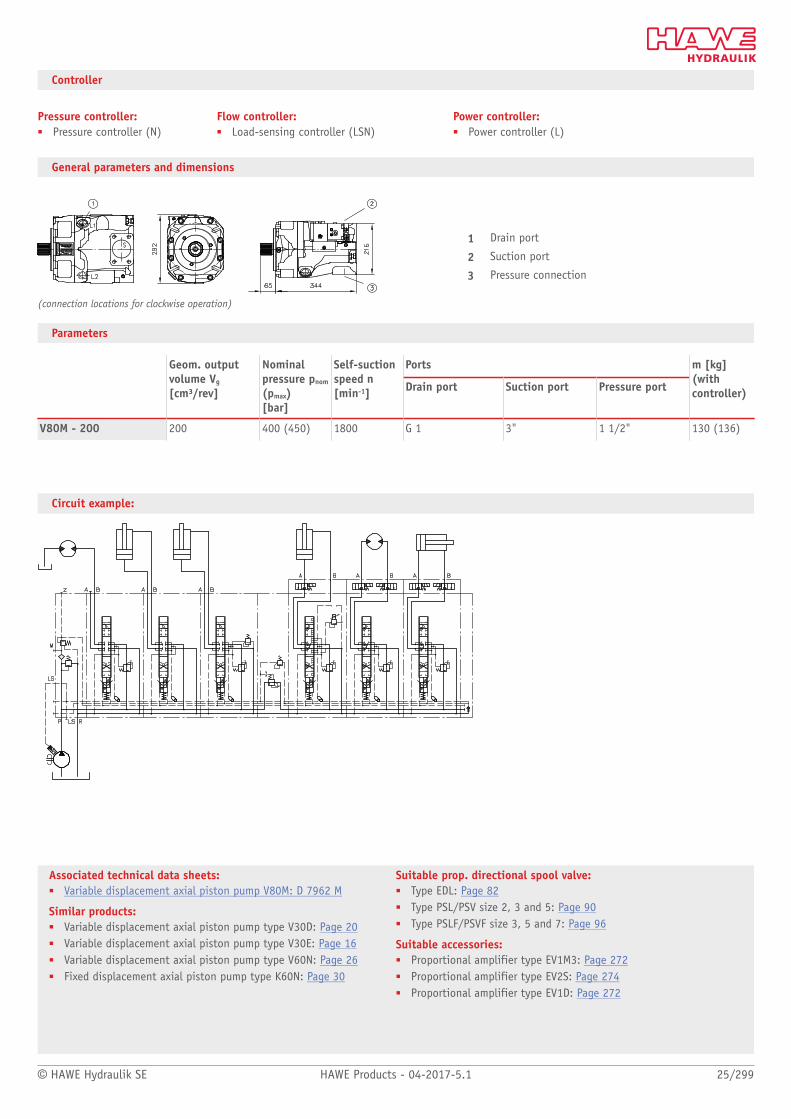
Controller
Pressure controller:■ Pressure controller (N)
Flow controller:■ Load-sensing controller (LSN)
Power controller:■ Power controller (L)
General parameters and dimensions
(connection locations for clockwise operation)
1 Drain port
2 Suction port
3 Pressure connection
Parameters
PortsGeom. outputvolume Vg
[cm³/rev]
Nominalpressure pnom
(pmax)[bar]
Self-suctionspeed n[min-1] Drain port Suction port Pressure port
m [kg](withcontroller)
V80M - 200 200 400 (450) 1800 G 1 3" 1 1/2" 130 (136)
Circuit example:

Individual pumps
26/299 HAWE Products - 04-2017-5.1 © HAWE Hydraulik SE
1.1 Variable displacement axial piston pump type V60N
Variable displacement axial piston pumps operate according to the bent axis principle. They
adjust the geometric output volume from maximum to zero. As a result they vary the ow
rate that is provided to the loads.
The axial piston pump type V60N is designed for open circuits in mobile hydraulics and
operate according to the swash plate principle. They are available with the option of a
thru-shaft for operating additional hydraulic pumps in series.
The pump is tted above all to the power take-off on commercial vehicle transmissions.
The range of pump controllers allows the axial piston pump to be used in a variety of
applications.
Features and benets:■ Optimized power-to-weight ratio■ High self-suction speed■ Wide controller options
Intended applications:■ Municipal trucks■ Cranes and lifting equipment■ Machines for forestry and agricultural purposes■ Truck-mounted concrete pumps
Nomen-clature:
Axial piston pumpVariable pump
Design: Single pump Multiple pump
pmax: System pressure: 400 barPeak pressure: 450 bar
Vg max: 130 cm³/rev
Design and order coding example
V60N - 110 R S F N - 1 - 0 - 03 /LSNR -2 - 320
Pressure specification [bar]
Stroke limitation With/without max. stroke limitation
Controller See section "Controller"
Release
Additional function
Housing version ■ Axial ports■ Radial ports with thru-shaft■ Radial ports
Seal material ■ NBR (N), FKM (V)
Flange version ■ Flange ISO 7653-1985 (Y, P)■ Flange ISO 3019-2 (G)■ Flange SAE J744 (X, Z, F)
Shaft version ■ ISO 14 parallel key splined shaft (D)■ Spline shaft DIN 5480 (M)■ Spline shaft SAE J744 (H, U, T, S, Q)
Rotating direction Anti-clockwise (L), clockwise (R)
Nominal size
Basic type

© HAWE Hydraulik SE HAWE Products - 04-2017-5.1 27/299
Function
Controller
Pressure controller■ Pressure controller (NR)■ Electro-proportional pressure controller with rising characteristic (PR)■ Electro-proportional pressure controller with falling characteristic (P1R)
Flow controller■ Load-sensing controller with integrated pressure limitation (LSNR, LSNRT)■ Flow controller for setting a constant, speed-independent volumetric ow (QNR)■ Electro-proportional ow controller with rising characteristic (V)■ Electro-proportional ow controller with falling characteristic (V1)
Power controller■ Power controller (L, /ZL)
28/299 HAWE Products - 04-2017-5.1 © HAWE Hydraulik SE
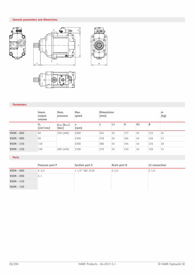
General parameters and dimensions
Parameters
Geom. outputvolume
Nom. pressure
Max. speed
Dimensions [mm]
m[kg]
Vg
[cm³/rev]pnom (pmax)[bar]
n[rpm]
L L1 H H1 B
V60N - 060 60 2500 254 55 177 45 115 24
V60N - 090 90 2300 278 55 184 45 120 27
V60N - 110 110
350 (400)
2200 280 55 194 45 125 30
V60N - 130 130 400 (450) 2100 270 55 210 45 130 31
Ports
Pressure port P Suction port S Drain port D LS connection
V60N - 060 G 3/4
V60N - 090
V60N - 110
V60N - 130
G 1
1 1/2" SAE J518 G 3/4 G 1/4

© HAWE Hydraulik SE HAWE Products - 04-2017-5.1 29/299
Associated technical data sheets:■ Variable displacement axial piston pump type V60N: D 7960 N
Similar products:■ Variable displacement axial piston pump type V30D:Page 20■ Variable displacement axial piston pump type V30E: Page 16■ Fixed displacement axial piston pump type K60N:Page 30■ Variable displacement axial piston pump type V80M:Page 24
Suitable prop. directional spool valves:■ Type EDL: Page 82■ Type PSL/PSV size 2, 3 and 5: Page 90■ Type PSLF/PSVF size 3, 5 and 7: Page 96
Suitable accessories:■ Proportional amplifier type EV1M3: Page 272■ Proportional amplifier type EV2S: Page 274■ Proportional amplifier type EV1D: Page 272
Circuit example:
V60N-130 RSFN-1-0-03 / LSNR-2-250PSV 31/D280-2 PSV 31-1– A 2 L 25/25/EA1/2– A 2 H 40/40/EA1/2 DRH– A 2 L 25/25/EA1/2– A 2 H 3/3 A 100 B 100/EA1/2 AL-0-D 4/120-BL-0-D 4/120– A 2 H 3/3/EA1/2 DRH– E 18-G 24
– A2 L 25/25/EA1/2– A2 L 25/25/EA1/2– A2 H 3/3/EA1/2 DRH– A2 H 3/3/EA1/2 DRH– E 1 - G24

Individual pumps
30/299 HAWE Products - 04-2017-5.1 © HAWE Hydraulik SE
1.1 Variable displacement axial piston pump type K60N
Fixed displacement axial piston pumps operate according to the bent axis principle. They
have a constant output volume and therefore deliver a constant ow rate at a specic
rotation speed.
The axial piston pump type K60N is designed for open circuits in mobile hydraulics and
operates based on the bent axis principle.
The pump is tted mainly to the power take-off on commercial vehicle transmissions.
Features and benets:■ Optimized power-to-weight ratio■ High rotation speed■ Different shaft and ange versions
Intended applications:■ Machines for forestry and agricultural purposes■ Cranes and lifting equipment■ Truck-mounted concrete pumps■ Municipal trucks
Nomen-clature:
Axial piston pumpConstant pump
Design: Single pump
pmax: 400 bar
Vg max: 108 cm3/rev
Design and order coding example
K60N - 064 R S F N - S - F12
Additional versions Bypass valve
Seal material ■ NBR (N), FKM (V)
Flange version ■ DIN ISO 7653 (Y)■ SAE-C, SAE-B J 744 (F)
Shaft version ■ ISO 14 parallel key splined shaft (D)■ SAE-C, SAE-B J 744 spline shaft (S)
Rotating direction Counter clockwise (L), clockwise (R)
Nominal size
Basic type
Function
© HAWE Hydraulik SE HAWE Products - 04-2017-5.1 31/299
Associated technical data sheets:■ Fixed displacement axial piston pump type K60N: D 7960 K
Similar products:■ Variable displacement axial piston pump type V30D: Page 20■ Variable displacement axial piston pump type V30E: Page 16■ Variable displacement axial piston pump type V60N: Page 26■ Variable displacement axial piston pump type V80M: Page 24■ Axial piston motor type M60N: Page 254
Suitable prop. directional spool valves:■ Type EDL: Page 82■ Type PSL/PSV size 2, 3 and 5: Page 90■ Type PSLF/PSVF size 3, 5 and 7: Page 96
Suitable load-holding valves:■ Type LHK, LHDV, LHT: Page 198
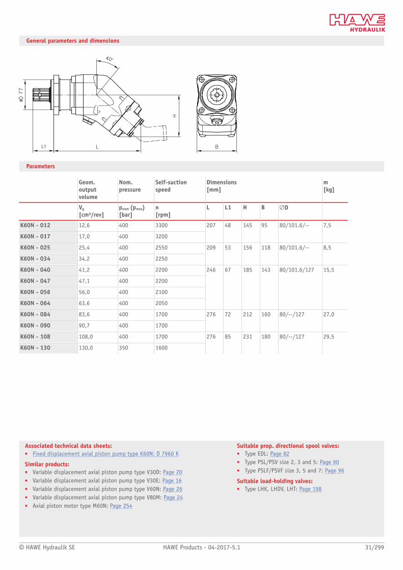
General parameters and dimensions
Parameters
Geom.outputvolume
Nom. pressure
Self-suction speed
Dimensions [mm]
m[kg]
Vg
[cm³/rev]pnom (pmax)[bar]
n[rpm]
L L1 H B #D
K60N - 012 12,6 400 3300
K60N - 017 17,0 400 3200
207 48 145 95 80/101.6/-- 7,5
K60N - 025 25,4 400 2550
K60N - 034 34,2 400 2250
209 53 156 118 80/101.6/-- 8,5
K60N - 040 41,2 400 2200
K60N - 047 47,1 400 2200
K60N - 056 56,0 400 2100
K60N - 064 63,6 400 2050
246 67 185 143 80/101.6/127 15,5
K60N - 084 83,6 400 1700
K60N - 090 90,7 400 1700
276 72 212 160 80/--/127 27,0
K60N - 108 108,0 400 1700
K60N - 130 130,0 350 1600
276 85 231 180 80/--/127 29,5

Individual pumps
32/299 HAWE Products - 04-2017-5.1 © HAWE Hydraulik SE
1.1 Air-driven hydraulic pump type LP
Air-driven hydraulic power packs are pneumatically driven, reciprocally acting plunger
pumps. They operate as pneumatic pressure ampliers with oscillating movement and
automatic stroke reversal control.
The air-driven hydraulic pump type LP can generate up to 1500 bar. It is available as an
single pump or as a hydraulic power pack with different tank sizes and valve banks. The
delivery ow is dependent on the air pressure set and the ow resistance currently present.
It can decay to standstill.
Applications are in laboratory presses, in xture design, in lubrication systems or in
potentially explosive atmospheres.
Features and benets:■ High operating pressures■ Suitable for explosion-proof systems and equipment
No electrical energy■ Hydraulic power packs with direct valve mounting
Intended applications:■ Construction and construction materials machinery■ xture design■ Testing and laboratory equipment
Nomen-clature:
Air driven hydraulic pumps
Design: Single pump
phydraulicmax : 1500 bar
pairmax : 10 bar
Qmax: 12 l/min
Design and order coding example
LP 125 - 16 E /S 81
Additional elements ■ Suction parts for hydraulic pumps
Design Hydraulic pump■ Ready-to-connect version■ Individual version for self-installation
Basic type, size Type LP, size 80, 125, 160
Function

© HAWE Hydraulik SE HAWE Products - 04-2017-5.1 33/299
Associated technical data sheets:■ Air-driven hydraulic pump type LP: D 7280■ Hydraulic power pack type LP: D 7280 H
Valve banks :■ Type VB:Page 114■ Type BWH(N):Page 120
General parameters and dimensions
Basic type andsize
pmax
[bar]Pressure ratio
Geom. volumeper doublestrokeVhydr [cm³]
Tapped port (air) Pipediameter for pressureconnection (hydr)
Dimensions [mm]
m[kg]
H H1 B T
8 700 1 : 200 1.5
...
LP80-
16 240 1 : 24 6
G 1/4Æ6 mm
119 94 121 85 5
8 1500 1 : 243 2
...
LP125-
30 160 1 : 16 28.3
G 3/8Æ8 mm, Æ10 mm
159 114 156 135 8.5
8 1500 1 : 400 2
...
LP160-
30 265 1 : 24 28.3
G 1/2 Æ8 mm, Æ10 mm
228 136 156 175 11.5

Individual pumps
34/299 HAWE Products - 04-2017-5.1 © HAWE Hydraulik SE
1.1 Hand pump type H, HE and HD
Hand pumps are a type of hydraulic pump. They generate a ow rate manually.
The hand pump type H and HE is single-acting. It draws in oil in one direction and pumps
it in the opposite direction. The hand pump type HD is double-acting. It pumps and draws
in the same quantity of oil in the pressure line during the forward and backward movement
of the hand lever. The hand pump type H, HE and HD is available for pipe connection and
manifold mounting.
The hand pump is particularly suitable as an emergency pump or for test benches.
Features and benets:■ Sturdy design■ Hand pumps with integrated tank■ Safety and drain valve
Intended applications:■ Shipbuilding■ Mining machinery■ xture design■ Testing and laboratory equipment Nomen-
clature:Piston pump
Design: Single acting hand pumpDouble acting hand pump
pmax: 800 bar
Vmax : 30 cm3/stroke
Design and order coding example
HD 13 AS - K 0,5 - 110
Pressure setting (bar)
With/without tank Usable volume Vuse. 0,35 l and 0,5 l
Additional elements ■ Drain valve (A)■ Pressure limiting valve (xed or manually adjustable) (S)
Basic type, size Type H (single-acting, open design), Type HE (single-acting, encapsulated design) Type HD (double-acting, encapsulated design)
■ With/without pressure resistant suction port■ Versions for manifold mounting
Function
Design with pressure limiting valve and drain valve

© HAWE Hydraulik SE HAWE Products - 04-2017-5.1 35/299
Associated technical data sheets::■ Manual pump type H, HD and HE: D 7147/1
General parameters and dimensions
H.. HE.. and HD..
pmax [bar] Vmax [cm³/stroke] Tapped ports (BSPP) m [kg]
P S
H 16 350 6
H 20 220 9.4
H 25 150 14.7
G 1/4 G 1/4 3.1
HE 3 800 3
HE 3 800 3
HD 13 350 13
HD 20 220 20
HD 30 150 30
G 1/4 G 1/4 and G 3/8 4.8
Pumps
36/299 HAWE Products - 04-2017-5.1 © HAWE Hydraulik SE
1.2 Hydraulic Unit
Compact hydraulic power pack type NPC 40
Compact hydraulic power pack type HC and HCW 42
Compact hydraulic power pack type KA and KAW 46
Compact hydraulic power pack type MPN 50
Compact hydraulic power pack type HK, HKF and HKL 54
Standard hydraulic power pack type FXU 58
Air-driven hydraulic power pack type LP 60
Connection block type A, B and C 62
Compact UnitModel KA und KAW
Compact unitModel HK, HKF und HKL

© HAWE Hydraulik SE HAWE Products - 04-2017-5.1 37/299
Compact hydraulic power packs
Type Design / tank volume (l) pmax
(bar)Vmax
(cm3/rev)
NPC Radial piston pump■ With integrated electric motor■ Direct current supply■ Suitable for short period operation
– Fill volume 1.0– Usable volume 0.65
11: 75012: 750
11: 0.4612: 0.46
HC, HCW Radial piston or gear pump■ With integrated electric motor■ 3-phase or AC version■ Suitable for intermittent operation
– Vertical approx. 1.16 – 2.5– Usable volume approx. 0.50 – 1.5
HP/LP:1: 700/1802: 700/180
1: 0.762: 1.59
KA, KAW Radial piston or gear pump■ With integrated electric motor■ 3-phase or AC version■ Suitable for intermittent operation
KA 2– Fill volume approx. 3.9 – 11.1– Vertical approx. 1.85 – 8.95
KA 4– Fill volume approx. 13 – 31– Vertical approx. 5 – 25
HP/LP:2: 700/1804: 700/180
HP/LP:2: 3.61/7.94: 9.17/30.2
MP, MPN Radial piston pump and/or gear pump■ With integrated electric motor■ Single-circuit or dual-circuit pump■ Suitable for intermittent or load/no load operation
– Fill volume approx. 17 – 100– Usable volume approx. 10 – 75
HP/LP:MP - 1: 700/220MP - 2: 700/200
MPN - 4: 700/220
HP/LP:MP - 1: 0.95/4.76MP - 2: 1.59/26
MPN - 4: 9.17/60
HK, HKF, HKL Radial piston pump and/or gear pump■ With integrated electric motor■ 3-phase version■ Suitable for continuous and intermittent operation
HK 2– Fill volume approx. 2.77– Usable volume approx. 0.85
HK 3– Fill volume approx. 4.65 – 6.1– Usable volume approx. 1.45 – 2.90
HK 4, HKF 4– Fill volume approx. 5.8 – 15.4– Usable volume approx. 1.9 – 11.1
HKL 3– Fill volume approx. 3.7 – 13– Usable volume approx. 1.7 – 9.1
HP/LP:HK - 2: 700HK - 3: 700/180HK - 4: 700/180
HKF - 4: 700/180
HKL - 3: 700/180
HP/LP:HK - 2: 1.59HK - 3: 4.58/4.8HK - 4: 9.17/17.0
HKF - 4: 9.17/17.0
HKL - 3: 6.11/14.5

38/299 HAWE Products - 04-2017-5.1 © HAWE Hydraulik SE
Standard hydraulic power packs
Type Design / tank volume (l) pmax
(bar)Vmax
(cm3/rev)
FXU Radial piston pump / dual-stage pump■ Standard hydraulic power pack
– Fill volume approx. 26-650
R: 700Z: 260RZ: 700/200
R: 64.2Z: 63RZ: 64.2/89.6
A, B, CConnection blockModel A, B, C
Connection blocks■ For connecting to the Hydraulic Unit■ Pumping Units
– Flange valve for Pipe connection or Valve assembly
700 20
LP Air-driven hydraulic pump■ Single pump■ Hydraulic power pack
– Fill volume approx. 5.8–33– Usable volume approx. 3.8–28
80: 700125: 700160: 700
80: 6.00125: 28.30160: 28.30

39/299 - -5.1 © HAWE Hydraulik SE

40/299 HAWE Products - 04-2017-5.1 © HAWE Hydraulik SE
1.2 Compact hydraulic power pack type NPC
Compact hydraulic power packs are a type of hydraulic power pack. They are characterised
by a highly compact design, since the motor shaft of the electric motor also acts as the
pump shaft.
The ready-for-connection compact hydraulic power pack type NPC is suitable for hydraulic
systems with operating mode S2. Type NPC includes a DC motor. The power pack is available
in a horizontal or vertical version. Either single-circuit systems or dual-circuit systems can
be selected. A radial piston pump or an external gear pump can be used as a hydraulic
pump.
The compact hydraulic power pack type NPC is suitable for use as a highly compact control
system, since the pressure-limiting valve is integrated and valve banks can be directly
mounted.
Features and benets:■ Very low space requirements and easy to transport■ Supplied with direct current at 12V DC or 24V DC■ Particularly suited to mobile applications and construction site operation■ Long lifetime and excellent reliability achieved by using radial piston pumps■ Environmentally sound thanks to low oil ll volumes and minimum cost of disposal■ Low costs for hydraulic uid■ Co-ordinated range of valves and accessories from the modular system
Intended applications:■ Riveting■ Brakes for wind power plants■ Hydraulic jigs■ Crimping■ Embossing
Nomen-clature:
Radial piston pump with integrated electricmotor (DC)
Design: Oil immersed compact hydraulic power packFor short period operation
pmax: 750 bar
Qmax: 1.36 lpm(Vg max = 0.76 cm3/rev)
Design and order coding example
NPC 11 / 0,87 - 1/170 - R - G12 BWN 1 - NN - 35 - 1 - G12
Valve assembly ■ BWN1, BWH1, VB01■ Can be directly assembled without connection blocks according to
D 7470 B/1, D 7302
Motor voltage 12V DC or 24V DC
Check valve With/without check valve
Pressure limiting valve and setting ■ 1 = Fixed■ 2 = Manually adjustable
Delivery ow [lpm]
Basic type, size Type NPC, size 11 and 12
© HAWE Hydraulik SE HAWE Products - 04-2017-5.1 41/299
Associated technical data sheets:■ Compact hydraulic power pack type NPC: D 7940
Directly mountable valve banks:■ Type VB: Page 114■ Type BWH, BWN: Page 120
■ Pressure switches type DG: Page 262■ Electronic pressure transducer type DT: D 5440 T/1, D 5440 T/2
Function
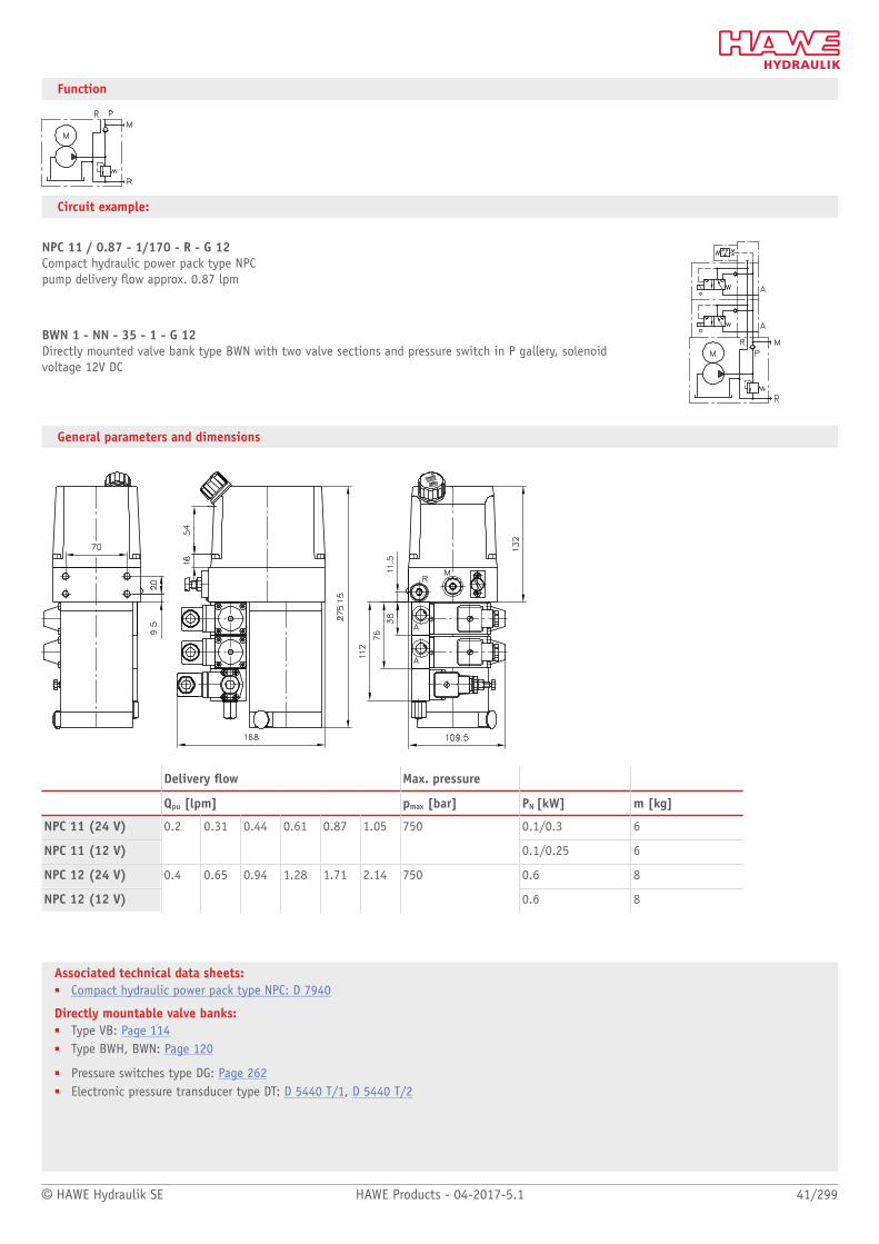
Circuit example:
NPC 11 / 0.87 - 1/170 - R - G 12Compact hydraulic power pack type NPC pump delivery ow approx. 0.87 lpm
BWN 1 - NN - 35 - 1 - G 12Directly mounted valve bank type BWN with two valve sections and pressure switch in P gallery, solenoidvoltage 12V DC
General parameters and dimensions
Delivery ow Max. pressure
Qpu [lpm] pmax [bar] PN [kW] m [kg]
NPC 11 (24 V) 0.1/0.3 6
NPC 11 (12 V)
0.2 0.31 0.44 0.61 0.87 1.05 750
0.1/0.25 6
NPC 12 (24 V) 0.6 8
NPC 12 (12 V)
0.4 0.65 0.94 1.28 1.71 2.14 750
0.6 8

Compact hydraulic power packs
42/299 HAWE Products - 04-2017-5.1 © HAWE Hydraulik SE
1.2 Compact hydraulic power pack type HC and HCW
Compact hydraulic power packs are a type of hydraulic power pack. They are characterised
by a highly compact design, since the motor shaft of the electric motor also acts as the
pump shaft.
The ready-for-connection compact hydraulic power pack type HC and HCW includes an
electric drive which runs in oil. The stator is securely attached to the housing (tank). The
compact hydraulic power pack is suitable for hydraulic systems with the operating modes
S2 or S3. The heat is dissipated via surface convection so that no external cooler is usually
necessary.
A radial piston pump or external gear pump can be used as a hydraulic pump.
The compact hydraulic power pack type type HC and HCW is suitable as a highly compact
control system, since connection blocks and valve banks can be directly mounted.
Features and benets:■ Long lifetime and high pressures thanks to use
of radial piston pumps■ Low oil ll volumes make it environmentally sound thanks to small amount of oil
to be disposed of and low costs for hydraulic uid■ Co-ordinated range of valves and accessories from modular system■ Suitable for vertical and horizontal installation
Intended applications:■ Clamping systems on machine tools and jigs■ Rivets and clinching equipment■ Welding robots
Nomen-clature:
Radial piston or gear pump with integratedelectric motor (three-phase or alternatingcurrent design)
Design: Oil immersed hydraulic power pack forintermittent service (S3-service)
pmax: Radial piston pump 700 barGear pump 180 bar
Qmax: Radial piston pump 4.4 lpm (Vg = 1.6 cm3/rev) Gear pump approx. 3.4 lpm (Vg = 1.3 cm3/rev)
Vusable max: 8 l
Design and order coding example
HC24 /0,6 - A1/400 - BWH1F-HH-1-1-G24 - 400V 50 Hz
Motor voltage 3 ~ 400V 50 Hz, 3 ~ 460V 60 Hz 1 ~ 230V 50 Hz, 1 ~ 110V 60 Hz (3~phase motor)
Optional directly mounted directional valve bank
Connection block
Pump version Single circuit pump■ Radial piston pump H (3-, 5- or 6-cylinders)
oder Gear pump Z
Basic type, size Type HC (3-phase motor) and type HCW (single-phase-motor, power reduction of 30 ... 50% depending on size), size 1 to 2,type HCG (direct current motor), size 1
■ Lying at low installation Heights (Model HC..L)■ Alternative standing version■ Usable volume Vusable 0.5 l to 1.5 l■ With/without uid level gauge■ With DC-motor (Type HCG) for short time operation

© HAWE Hydraulik SE HAWE Products - 04-2017-5.1 43/299
Function
Example circuit:
HC 24/0.64
Pump unit type HC, size 24, pump delivery ow approx. 0.64 lpm
- A1/400
Connection block type A and pressure-limiting valve (400 bar)
- BWH1F - RH1 - 1 - 1 - G 24
Directly mounted valve bank type BWH 1
BWH1F-RH-1-1-G24
HC24/0.64 A1/400

44/299 HAWE Products - 04-2017-5.1 © HAWE Hydraulik SE
General parameters and dimensions
Radial piston pump (3 cylinders) Gear pump
Max.pressure Delivery ow
Max.pressure Delivery ow Dimensions [mm]
pmax
[bar]
Qpu
[lpm]50 Hz
Qpu
[lpm]60 Hz
pmax
[bar]
Qpu
[lpm]50 Hz
Qpu
[lpm]60 Hz
PN
[kW] 1)m [kg] 2) H B T
HC 14 700 - 160 0.2 - 1.05 0.2 - 1.2 - - - 0.18
HC 12 600 - 120 0.4 - 2.15 0.5 - 2.5 - - - 0.25
6.3 197 120 120
HC 24 700 - 185 0.27 - 2.27 0.3 - 2.7 150 0.4 - 1.6 0.5 - 1.9 0.55
HC 22 700 - 140 0.52 - 4.41 0.6 - 5.3 150 0.9 - 3.4 1.1 - 4 0.55
10.1 243 148 148
1) The actual power consumption depends on the respective operation pressure and can be up to 1.5 x PN
2) Without oil lling

© HAWE Hydraulik SE HAWE Products - 04-2017-5.1 45/299
Associated technical data sheets:■ Compact hydraulic power pack type HC and HCW: D 7900■ Compact hydraulic power pack type HCG: D 7900 G
Connection blocks:■ Type A, B and C: Page 62
Directly mountable valve banks:■ Type VB: Page 114■ Type BWH, BWN: Page 120
Directly mountable valve banks:■ Type BA: Page 144■ Type BVH: Page 124
Circuit example:
HC 24/0.64 - A2/400 - BWH 1 F 1-DH3 R/230-33-G24 - 3x400V 50Hz
1 Compact hydraulic power pack2 Connection block3 Adapter plate4 Valve section5 End plate
Compact hydraulic power packs
46/299 HAWE Products - 04-2017-5.1 © HAWE Hydraulik SE
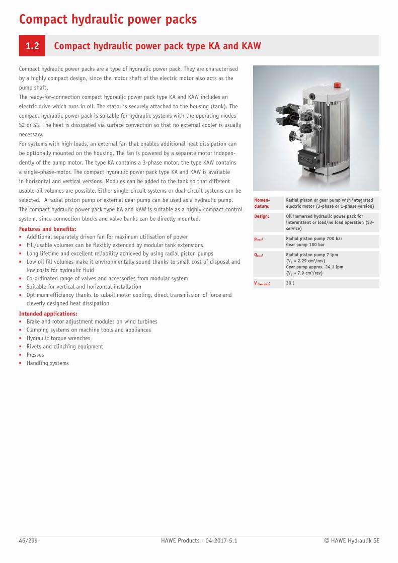
1.2 Compact hydraulic power pack type KA and KAW
Compact hydraulic power packs are a type of hydraulic power pack. They are characterised
by a highly compact design, since the motor shaft of the electric motor also acts as the
pump shaft.
The ready-for-connection compact hydraulic power pack type KA and KAW includes an
electric drive which runs in oil. The stator is securely attached to the housing (tank). The
compact hydraulic power pack is suitable for hydraulic systems with the operating modes
S2 or S3. The heat is dissipated via surface convection so that no external cooler is usually
necessary.
For systems with high loads, an external fan that enables additional heat dissipation can
be optionally mounted on the housing. The fan is powered by a separate motor indepen-
dently of the pump motor. The type KA contains a 3-phase motor, the type KAW contains
a single-phase-motor. The compact hydraulic power pack type KA and KAW is available
in horizontal and vertical versions. Modules can be added to the tank so that different
usable oil volumes are possible. Either single-circuit systems or dual-circuit systems can be
selected. A radial piston pump or external gear pump can be used as a hydraulic pump.
The compact hydraulic power pack type KA and KAW is suitable as a highly compact control
system, since connection blocks and valve banks can be directly mounted.
Features and benets:■ Additional separately driven fan for maximum utilisation of power■ Fill/usable volumes can be exibly extended by modular tank extensions■ Long lifetime and excellent reliability achieved by using radial piston pumps■ Low oil ll volumes make it environmentally sound thanks to small cost of disposal and
low costs for hydraulic uid■ Co-ordinated range of valves and accessories from modular system■ Suitable for vertical and horizontal installation■ Optimum efficiency thanks to suboil motor cooling, direct transmission of force and
cleverly designed heat dissipation
Intended applications:■ Brake and rotor adjustment modules on wind turbines■ Clamping systems on machine tools and appliances■ Hydraulic torque wrenches■ Rivets and clinching equipment■ Presses■ Handling systems
Nomen-clature:
Radial piston or gear pump with integratedelectric motor (3-phase or 1-phase version)
Design: Oil immersed hydraulic power pack forintermittent or load/no load operation (S3-service)
pmax: Radial piston pump 700 bar Gear pump 180 bar
Qmax: Radial piston pump 7 lpm (Vg = 2.29 cm3/rev) Gear pump approx. 24.1 lpm (Vg = 7.9 cm3/rev)
V tank max: 30 l
© HAWE Hydraulik SE HAWE Products - 04-2017-5.1 47/299
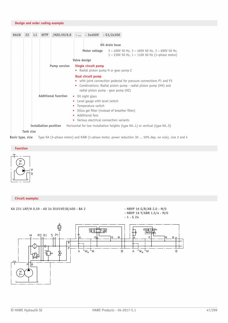
Design and order coding example
KA28 22 L1 KFTP /HZ0,59/8,8 - ... - 3x400V - G1/2x300
Oil drain hose
Motor voltage 3 ~ 400V 50 Hz, 3 ~ 460V 60 Hz, 3 ~ 690V 50 Hz, 1 ~ 230V 50 Hz, 1 ~ 110V 60 Hz (1~phase motor)
Valve design
Pump version Single circuit pump■ Radial piston pump H or gear pump Z
Dual circuit pump■ with joint connection pedestal for pressure connections P1 and P3■ Combinations: Radial piston pump - radial piston pump (HH) and
radial piston pump - gear pump (HZ)
Additional function ■ Oil sight glass■ Level gauge with level switch■ Temperature switch■ Silica gel lter (instead of breather lter)■ Additional fans■ Various electrical connection variants
Installation position Horizontal for low installation heights (type KA..L) or vertical (type KA..S)
Tank size
Basic type, size Type KA (3~phase motor) and KAW (1~phase motor, power reduction 30 ... 50% dep. on size), size 2 and 4
Function
Circuit example:
KA 231 LKP/H 0.59 - AX 34 D101VE1B/400 - BA 2 - NBVP 16 G/R/AB 2.0 - M/0 - NBVP 16 Y/ABR 1.5/4 - M/0 - 1 - G 24

48/299 HAWE Products - 04-2017-5.1 © HAWE Hydraulik SE
General parameters and dimensions
3-cylinder radial piston pump 6-cylinder radial piston pump Gear pump
pmax
[bar]
Qmax
[lpm] 50 Hz
Qmax
[lpm] 60 Hz
pmax
[bar]
Qmax
[lpm] 50 Hz
Qmax
[lpm] 60 Hz pmax[bar]
Qmax
[lpm] 50 Hz
Qmax
[lpm] 60 Hz
PN
[kW]
KA 21 700 - 45 0,63 -10,02
0,76 -12,05
360 - 55 1,26 - 7,84 1,52 - 9,42 170 - 60 2,23 - 6,7 2,68 - 8,04 0,55
KA 22 700 - 140 0,63 - 0,02 0,76 -12,05
700 - 180 1,26 - 7,84 1,52 - 9,42 170 - 55 2,23 -22,04
2,68 -26,47
1,1
KA 23 700 - 60 0,31 - 4,89 0,37 - 5,93 485 - 30 0,62 - 9,79 0,75 -11,85
170 - 50 1,09 - 4,90 1,32 - 5,94 0,37
KA 24 700 - 160 0,31 - 4,89 0,37 - 5,93 700 - 80 0,62 - 9,79 0,75 -11,85
170 - 65 1,09 -10,74
1,32 -13,04
0,75
KA 26 700 - 160 0,63 -10,02
0,76 -12,05
700 - 205 1,26 - 7,84 1,52 - 9,42 170 - 65 2,23 -22,04
2,68 -26,47
1,4
KA 28 700 - 185 0,31 - 4,89 0,37 - 5,93 700 - 90 0,62 - 9,79 0,75 -11,85 170 - 75 1,09 -10,74
1,32 -13,04
1.2
3-cylinder radial piston pump 6-cylinder radial piston pump Gear pump
pmax
[bar]
Qmax
[lpm] 50 Hz
Qmax
[lpm] 60 Hz
pmax
[bar]
Qmax
[lpm] 50 Hz
Qmax
[lpm] 60 Hz pmax[bar]
Qmax
[lpm] 50 Hz
Qmax
[lpm] 60 Hz
PN
[kW]
- 2.6KA 42 700 - 220 0.84 - 11.8 2.0 - 14.4 700 - 110 3.3 - 23.8 4.0 - 28.9 200 - 130 1.6 - 18.0 2.0 - 22.0
- 3.9
- 1,5
- 2,2
KA 44 700 - 220 1.6 - 5.98 1,01 - 7,25 700 - 110 1,68 -11,97
2,04 -14,53
200 - 130 0,84 - 9,1 1,01 - 11,1
- 3,0

© HAWE Hydraulik SE HAWE Products - 04-2017-5.1 49/299
Associated technical data sheets:■ Compact hydraulic power packs type KA:
D 8010, D 8010-4
Similar products:■ Type HC, HCG: Page 42
Suitable connection blocks:■ Type A, B and C: Page 62
Directly mountable valve banks:■ Type VB: Page 114■ Type BWH, BWN:Page 120■ Type SWR, SWS: Page 76■ Type BA: Page 144■ Type BVH: Page 124
Circuit example:
KA 281 S16K/H3.61-FSHS-24VDC-A 14/230 -BVH 11 W/CZ52/117GM/B3.5H -82 - AC1002/130/3A -XM 24 3x400V 50Hz

Compact hydraulic power packs
50/299 HAWE Products - 04-2017-5.1 © HAWE Hydraulik SE
1.2 Compact hydraulic power pack type MPN
Compact hydraulic power packs are a type of hydraulic power pack. They are characterised
by a highly compact design, since the motor shaft of the electric motor also acts as the
pump shaft.
The ready-for-connection compact hydraulic power pack type MPN and MPNW includes an
electric drive which runs in oil. The stator is securely attached to the housing (tank). The
compact hydraulic power pack is suitable for hydraulic systems with the operating modes
S2 or S3. The heat is dissipated via surface convection so that no external cooler is usually
necessary.
The type MPN contains a 3-phase motor, the type MPNW contains a single-phase-motor.
Different tank sizes enable different usable oil quantities. Either single-circuit systems
or dual-circuit systems can be selected. A radial piston pump , an external gear pump or
internal gear pump can be used as a hydraulic pump.
The compact hydraulic power pack type MPN and MPNW is suitable as a highly compact
control system, since connection blocks and valve banks can be directly mounted.
Features and benets:■ Intermittent or load/no load operation (S2-/S3-/S6-service)■ Long lifetime and excellent reliability achieved by using radial piston pumps■ Low oil ll volumes make it environmentally sound thanks to small cost of disposal and
low costs for hydraulic uid■ Two-stage valves and switch units for press control systems can be directly ange
mounted■ Co-ordinated range of valves and accessories from modular system■ Dual-circuit pumps available
Intended applications:■ Brake and rotor adjustment modules on wind turbines■ Counterbalance as well as machine tools■ Presses and other shaping machines■ Handling and clamping systems on machine tools and xtures■ Lubrication systems
Nomen-clature:
Radial piston and/or gear pump withintegrated motor single or dual-circuit pump
Design: Oil immersed hydraulic power pack for intermittent or load/no load operation (S2-/S3-/S6-service)
pmax: Radial piston pump 700 bar (high pressure),gear pump 220 bar (low pressure)
Qmax: 12.4 lpm (high pressure) (Vg = 9.17 cm3/rev)83 lpm (low pressure) (Vg = 61 cm3/rev)
Vt max: 100 l

© HAWE Hydraulik SE HAWE Products - 04-2017-5.1 51/299
Design and order coding example
MPN 44 - H 1,5 - B10.20 D - ... - 3 ~ 230V 50 Hz
Motor voltage 3 ~ 230/400V Δγ 50 Hz, 3 ~ 500V γ 50 Hz, 1 ~ 230V 50 Hz, 1 ~ 110V 60 Hz (single-phase-motor)
Valve mounting
Additional options ■ Level gauge■ Level switch■ Temperature switch■ Various means of electrical connection
Design ■ For installation in self-made oil tanks: as single pump or cover plate version■ With tank, usable volume Vusable 10 l to 75 l
Pump version Single-circuit pump■ Radial piston pump H or gear pump Z■ Internal gear pump IZ
Dual-circuit pump■ Combinations:
■ Radial piston pump - radial piston pump (HH)■ Radial piston pump - gear pump (HZ)
Basic type, size Type MPN (3-phase motor) and MPNW (single-phase motor)Depending on the size, single-phase motor has 30 to 50% less power
Function
Single stage pump Dual stage pump(radial piston pump, gear pump) (radial piston/gear pump,
gear pump/gear pump)
Installation pump
Hydraulic power pack(incl. tank)
Installation pump
Hydraulic power pack(incl. tank)
Circuit example:

52/299 HAWE Products - 04-2017-5.1 © HAWE Hydraulik SE
General parameters and dimensions
Single-circuit pump, dual-circuit pump(without tank)
Compact hydraulic power pack(tank with mounted valves)
Radial piston pump (3 cyl.) Gear pump
Max.pressure Delivery ow
Max.pressure Delivery ow Dimensions [mm]
pmax
[bar]
Qpu
[lpm]50 Hz
Qpu
[lpm]60 Hz
pmax
[bar]
Qpu
[lpm]50 Hz
Qpu
[lpm]60 Hz
PN
[kW]1)m [kg]2) H12) H2max ÆD
MPN 42 700 - 250 2,39 - 7,33 2,87 - 8,8 200 - 60 8,46 - 30,02 10,2 - 36,02 2,1
MPN 44 700 - 250 1,53 - 5,37 1,84 - 6,44 200 - 55 5,37 - 25,99 6,4 - 31,19 2,1
12,9 251/258 431
MPN 46 700 - 250 3,16 - 11,12 3,8 - 13,34 200 - 40 12,41 - 71,73 14,89 - 86,08 3,0
MPN 48 700 - 330 2,36 - 4,06 2,83 - 4,87 220 - 60 4,16 - 34,91 4,99 - 41,89 3,0
18,5 274/281 454
MPN 404 700 - 340 3,1 - 3,49 3,7 - 4,19 220 - 45 2,7 - 68,16 2,25 - 81,79 4,2 26,4 298/313 486
165
1) The actual power consumption is dependent on the respective operation pressure and can be up to 1.5xPN
2) Values apply to radial piston pump/gear pump versions
Version with tank:
Size Tank size H [mm] W [mm] D [mm]
B 25 458 402 250
B 55 470 560 350
B 110 495 560 350
B 25 L 283 623 250
MPN 4.
B 55 L 305 560 350

© HAWE Hydraulik SE HAWE Products - 04-2017-5.1 53/299
Associated technical data sheets:■ Compact hydraulic power pack type MPN and MPNW: D 7207
Connection blocks:■ Type A, B and C: Page 62
Flange-mountable valve banks:■ Type VB: Page 114■ Type BWH, BWN: Page 120■ Type BA: Page 144■ Type BVH: Page 124
Circuit example:
MPN 44-Z 8.8-B 10 KT -AS 1 F 3/160 -BA 2 -NBVP 16 G/R-GM/NZP 16 LZY 5/50-G 8 MA/GM/3-X 84 V-DG 5E-250-1/4 -NBVP 16 G-GM/NZP 16 LZY 5/50-G 8 MA/GM/3-X 84 V-DG 62 -1-G 24 -X 84 V-9/250 -3 x 400/230 V 50 Hz
Compact hydraulic power packs
54/299 HAWE Products - 04-2017-5.1 © HAWE Hydraulik SE
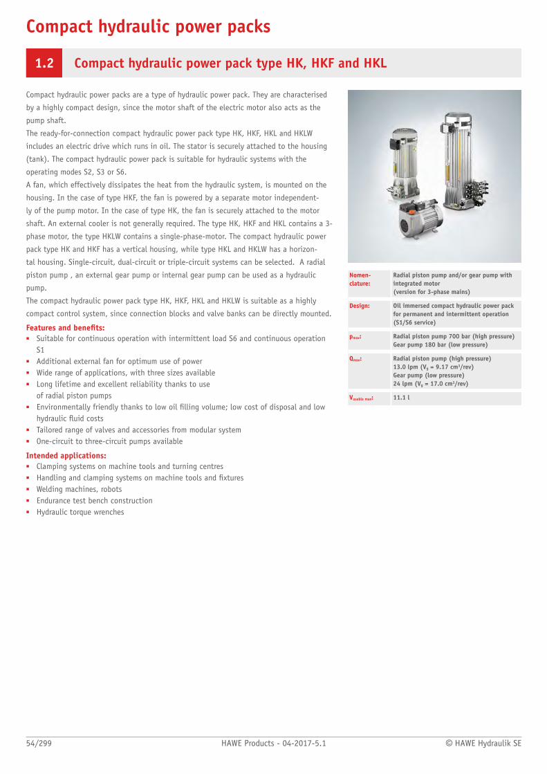
1.2 Compact hydraulic power pack type HK, HKF and HKL
Compact hydraulic power packs are a type of hydraulic power pack. They are characterised
by a highly compact design, since the motor shaft of the electric motor also acts as the
pump shaft.
The ready-for-connection compact hydraulic power pack type HK, HKF, HKL and HKLW
includes an electric drive which runs in oil. The stator is securely attached to the housing
(tank). The compact hydraulic power pack is suitable for hydraulic systems with the
operating modes S2, S3 or S6.
A fan, which effectively dissipates the heat from the hydraulic system, is mounted on the
housing. In the case of type HKF, the fan is powered by a separate motor independent-
ly of the pump motor. In the case of type HK, the fan is securely attached to the motor
shaft. An external cooler is not generally required. The type HK, HKF and HKL contains a 3-
phase motor, the type HKLW contains a single-phase-motor. The compact hydraulic power
pack type HK and HKF has a vertical housing, while type HKL and HKLW has a horizon-
tal housing. Single-circuit, dual-circuit or triple-circuit systems can be selected. A radial
piston pump , an external gear pump or internal gear pump can be used as a hydraulic
pump.
The compact hydraulic power pack type HK, HKF, HKL and HKLW is suitable as a highly
compact control system, since connection blocks and valve banks can be directly mounted.
Features and benets:■ Suitable for continuous operation with intermittent load S6 and continuous operation
S1■ Additional external fan for optimum use of power■ Wide range of applications, with three sizes available■ Long lifetime and excellent reliability thanks to use
of radial piston pumps■ Environmentally friendly thanks to low oil lling volume; low cost of disposal and low
hydraulic uid costs■ Tailored range of valves and accessories from modular system■ One-circuit to three-circuit pumps available
Intended applications:■ Clamping systems on machine tools and turning centres■ Handling and clamping systems on machine tools and xtures■ Welding machines, robots■ Endurance test bench construction■ Hydraulic torque wrenches
Nomen-clature:
Radial piston pump and/or gear pump withintegrated motor (version for 3-phase mains)
Design: Oil immersed compact hydraulic power packfor permanent and intermittent operation(S1/S6 service)
pmax: Radial piston pump 700 bar (high pressure)Gear pump 180 bar (low pressure)
Qmax: Radial piston pump (high pressure) 13.0 lpm (Vg = 9.17 cm3/rev)Gear pump (low pressure) 24 lpm (Vg = 17.0 cm3/rev)
Vusable max: 11.1 l

© HAWE Hydraulik SE HAWE Products - 04-2017-5.1 55/299
Design and order coding example
HK 34 8 LST - H 3,6 3 x 400V 50Hz
Motor voltage 3 ~ 230/400V Δγ 50 Hz, 3 ~ 265/460V Δγ 60 Hz 1 ~ 230V 50 Hz, 1 ~ 115V 60 Hz (1~phase motor)
Pump version Single circuit pump■ Radial piston pump H, gear pump Z, internal gear pump IZ
Dual circuit pump with joint connection pedestal for pressure ports P1 and P3■ Combinations:
■ Radial piston pump - radial piston pump (HH)■ Radial piston pump - gear pump (HZ)
Dual circuit pump with separate connection pedestals■ Radial piston pump H or gear pump Z
Additional functions ■ Temperature and level switch, single or double version■ Additional leakage port (Type HK 4.L)
Tank size Type HK: Usable volume Vusable 0.85 l to15.4 l, Type HKL: Usable volume Vusable 1.7 l to 9.1 l
■ Various ller neck designs
Basic type, size Type HK, size 2 to 4, type HKF (with auxiliary blower for increased cooling), size 4Type HKL (3~phase motor) and HKLW (1~phase motor), size 3
Additional versions:■ With molded motor■ With frequency-controlled drive
Function
Single stage pump Dual stage pump(radial piston pump, or gear pump)
(radial piston/radial piston pump, or gear pump/gear pump, or radial piston pump/gear pump)
Joint pump pedestal Separate pump pedestals
Triple-circuit pump(only radial piston pump)
Separate pump pedestals

56/299 HAWE Products - 04-2017-5.1 © HAWE Hydraulik SE
General parameters and dimensions
HK..Terminal box
(only with type HK 4.)Pump pedestal 2
Pump pedestal 1
1 Terminal box
2 Pump pedestal 2 (only for type HK 4.)
3 Pump pedestal 1
HKL..
Radial piston pump Gear pump
Max.pressure Delivery ow
Max.pressure Delivery ow Dimensions [mm]
pmax
[bar]
Qpu
[lpm]50 Hz
Qpu
[lpm]60 Hz
pmax
[bar]
Qpu
[lpm]50 Hz
Qpu
[lpm]60 Hz
PN
[kW]1) Hmax B Tm [kg]
HK 24 700 - 220 0.46 - 1.77 0.55 - 2.12 - - - 0.55 340 196 196 13
HK 33 560 - 100 1.25 - 6.5 1.5 - 7.8 170 - 100 2.7 - 6.9 3.24 - 8.28 0.8 405 212 212 20.5
HK 34 700 - 170 1.25 - 6.5 1.5 - 7.8 170 - 160 2.7 - 6.9 3.24 - 8.28 1.1 405 212 212 20.5
HK(F) 43 610 - 90 2.08 - 13.1 3.36 - 15.72 170 - 80 4.5 - 16 3.29 - 19.2 1.5 460 240 240 29
HK(F) 44 2.2 460 240 240 29
HK(F) 48
700 - 130 2.08 - 13.1 2.5 - 15.72 170 - 110 4.5 - 24 3.29 - 28.8
3 833 240 240 40
HKL(W) 32
HKL(W) 34
700 - 220 1.65 - 8.7 1.98 - 10.44 170 - 130 2.7 - 11.3 3.24 - 13.56 1.8 358 617 196 19.2
HKL 38 700 - 220 1.65 - 8.7 1.98 - 10.44 170 - 130 2.7 - 11.3 3.24 - 13.56 2.2 358 617 196 22.2
1) The actual power consumption is dependent on the respective operation pressure and can be up to 1.5 x PN

© HAWE Hydraulik SE HAWE Products - 04-2017-5.1 57/299
Associated technical data sheets:■ Compact hydraulic power pack type HK 4: D 7600-4■ Compact hydraulic power pack type HK 3: D 7600-3■ Compact hydraulic power pack type HK 2: D 7600-2■ Compact hydraulic power pack type HKL and HKLW: D 7600-3L
Connection blocks:■ Type A, B and C: Page 62
Directly mountable valve banks:■ Type VB: Page 114■ Type BWH, BWN: Page 120■ Type BA:Page 144■ Type BVH: Page 124
Circuit examples:
HKF 489 D-DT/1P1M-H2.6
-AS1/260
-BWN1F-HH5R-1-G24
-3x400/230V50Hz
Compact hydraulic power pack HKF 489 with level switch with two switch points (coding D-D);
temperature switch (coding T) with Harting plug coding P1 and oil ller (coding M)
HK449/1P1-H 2.5-Z6.9
-AS1/400-G24
-AS1/110-G24
-3x400/230V50Hz
Compact hydraulic power pack HK 44 with radial piston pump H 2.5 and gear pump Z 6.9 on separate pump pedestals,
two connection blocks (type AS1/..) with pressure limiting valve (400 bar and 110 bar) and idle circulation valve (mounting of valve banks
possible)

Hydraulic power pack
58/299 HAWE Products - 04-2017-5.1 © HAWE Hydraulik SE
1.2 Standard hydraulic power pack type FXU
Standard hydraulic power packs are a type of hydraulic power pack. They are characterised
by their very exible design and customer-specic modular adjustment options.
Units of the FXU (Flexunit) range are used to create pressure for stationary oil-hydraulic
installations.
The units have oil containers made either of aluminium or of steel. The pump is located in
the tank. Single pumps or combinations of pumps are possible.
Both radial piston pumps and external gear pumps are used as well as combinations of
external gear pumps with radial piston pumps.
The pumps are installed below the tank cover in an aluminium container or in a steel
container.
Features and benets:■ Hydraulic power pack for continuous operation (S1 operation)■ Long lifetime and excellent reliability when using radial piston pumps■ Low noise production when using gear pumps■ Combinations of radial piston pumps and gear pumps available for dual-stage systems■ Quick to congure due to tailored modular system■ Customer-specic documentation with EPlan Fluid schematic, step model and adjusted
data sheet■ Possible to directly mount all HAWE valve banks
Intended applications:■ Machine tools with a continuous ow rate requirement■ Recycling systems■ Plastics machinery■ Unloading stations in material handling■ Pressing applications such as vulcanising and briquetting■ Incremental launching systems for bridge building
Nomenclature: Standard hydraulic power pack (S1 operation)Single-circuit pump, dual-circuit pumpWith radial piston pump and/or gear pump inthe tank
Version: Radial piston pump and/or gear pump
pmax: HP/LP: 700/280 bar
Qmax: HP/LP: 91/80 lpmRadial piston pump: Vg = 64.2 cm³/revGear pump: Vg = 63 cm³/rev
VTank max: 565 l
Design and order coding example
FXU - Z9 BL 44 - F020/OA - NT1/A - UA - V4,0-3 x 400/230 V 50 Hz - A3/185
Connection block
Motor version, nominal power, nominal voltage
Pedestrial
Monitoring
Filter
Tank Nominal size
Pump Radial piston pump (R...) or gear pump (Z...)
Basic type

© HAWE Hydraulik SE HAWE Products - 04-2017-5.1 59/299
Associated technical data sheets:■ Standard hydraulic power pack type FXU: D 6020■ Radial piston pump type R and RG: D 6010■ Dual-stage pump type RZ: D 6910
Suitable connection blocks■ Connection blocks type A for hydraulic power packs: D 6905 A/1■ Connection blocks type B for hydraulic power packs: D 6905 B■ Connection block type C 5 and C 6: D 6905 C
Flange-mountable valve banks■ Valve bank (nominal size 6) type BA: D 7788■ Valve bank type BNG: D 7788 BNG■ Valve bank (directional seated valve) type BVH: D 7788 BV■ Valve bank (directional seated valve) type VB: D 7302■ Valve bank (directional seated valve) type BWN and BWH:
D 7470 B/1
Function
General parameters and dimensions
BL ... BS ...
Tank size H [mm] L [mm] B [mm] b [mm] c [mm] H1 [mm] Vmax tank [l]
BL 30 291 490 350 326 176 445 26
BL 44 324 515 425 341 241 614.5 40
BL 70 374 605 475 422.5 282.5 659.5 63
BS 100 693 670 528 -- -- 667 90
BS 160 693 910 528 -- -- 759.5 145
BS 250 693 1310 528 -- -- 759.5 225
BS 400 765 1270 904 -- -- 783 360
Standard power packs
60/299 HAWE Products - 04-2017-5.1 © HAWE Hydraulik SE
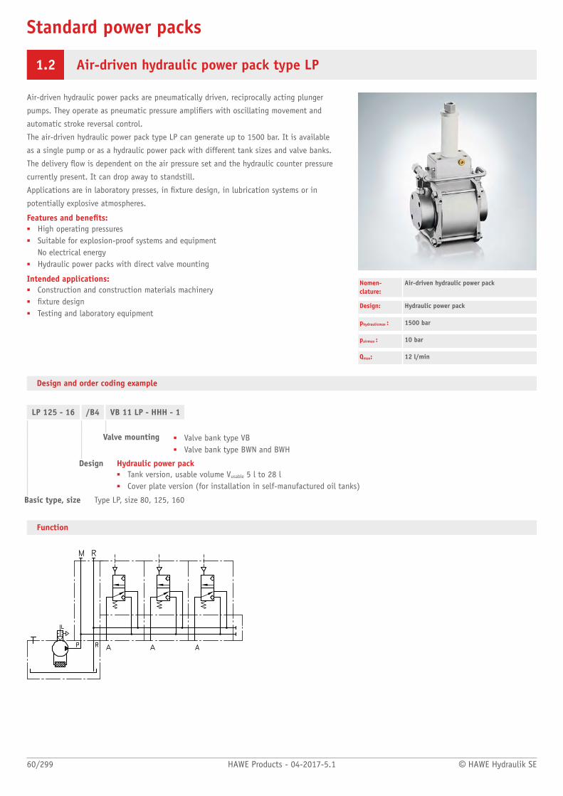
1.2 Air-driven hydraulic power pack type LP
Air-driven hydraulic power packs are pneumatically driven, reciprocally acting plunger
pumps. They operate as pneumatic pressure ampliers with oscillating movement and
automatic stroke reversal control.
The air-driven hydraulic power pack type LP can generate up to 1500 bar. It is available
as a single pump or as a hydraulic power pack with different tank sizes and valve banks.
The delivery ow is dependent on the air pressure set and the hydraulic counter pressure
currently present. It can drop away to standstill.
Applications are in laboratory presses, in xture design, in lubrication systems or in
potentially explosive atmospheres.
Features and benets:■ High operating pressures■ Suitable for explosion-proof systems and equipment
No electrical energy■ Hydraulic power packs with direct valve mounting
Intended applications:■ Construction and construction materials machinery■ xture design■ Testing and laboratory equipment
Nomen-clature:
Air-driven hydraulic power pack
Design: Hydraulic power pack
phydraulicmax : 1500 bar
pairmax : 10 bar
Qmax: 12 l/min
Design and order coding example
LP 125 - 16 /B4 VB 11 LP - HHH - 1
Valve mounting ■ Valve bank type VB■ Valve bank type BWN and BWH
Design Hydraulic power pack■ Tank version, usable volume Vusable 5 l to 28 l■ Cover plate version (for installation in self-manufactured oil tanks)
Basic type, size Type LP, size 80, 125, 160
Function

© HAWE Hydraulik SE HAWE Products - 04-2017-5.1 61/299
Associated technical data sheets:■ Air-driven hydraulic pump type LP: D 7280■ Hydraulic power pack type LP: D 7280 H
Valve banks :■ Type VB:Page 114■ Type BWH(N):Page 120
General parameters and dimensions
Basic type and size B H T h Vmax tank (l) m(kg)
LP 80-..B4 200 242,5 200 94 7 5,7
LP 125-..B4 200 242,5 200 110 5,8 5,7
LP 125-..B10 324 332,5 200 132 16,6 8,5
LP 125-..B25 402 410 250 130 34 15,1
LP 160-..B10 324 332,5 200 132 13,5 8,5
LP 160-..B25 402 410 250 130 33 15,1
Circuit example:
LP 125-10/B 10 D-VB 11 LM-NRN-1-G 24
Hydraulic power pack in tank version with air-driven hydraulic pump type LP125-10,
tank size B10 as well as level switch D (N/C contact) and valve bank type VB11 attached.

Mounted valves
62/299 HAWE Products - 04-2017-5.1 © HAWE Hydraulik SE
1.2 Connection block type A, B and C
A connection block represents the connecting link between the hydraulic power pack and
the hydraulic control. The connection blocks described here are suitable for combining with
compact hydraulic power packs.
A valve bank can be directly attached to the connection block type A such that a compact
hydraulic control unit is produced. As standard the type A contains a pressure-limiting
valve that can be supplemented with a pressure or return line lter, or an idle circulation
valve, among other items. The connection block type B controls single-acting cylinders,
e.g. in pallet lifting equipment. The integrated pressure-limiting valve limits the maximum
lifting force. The lowering speed is adjusted using the integrated throttle. The connection
block type C has only a pump and return port and is used in hydraulic systems with
decentral valve blocks.
The connection blocks type A, B and C can be combined, e.g. with the compact hydraulic
power packs type KA, HK and MPN.
Features and benets:■ Enables compact and sturdy direct mounting of ongoing components at the compact
power packs of HAWE Hydraulik■ Intermediate plates enable versatile addition of other components■ Efcient and space saving solution for mounting individual valves or valve banks to
single and dual circuit pumps■ Pressure/return line lters, pressure-limiting valves, pressure switches, etc. can be
directly integrated
Intended applications:■ Lifting devices■ Machine tools■ Modules for braking or rotor blade adjustment at wind power systems■ Tracking systems for solar panels and parabolic antennas
Nomen-clature:
Connection blocks to the completion ofhydraulic power packs
Design: Add-on valve enabling pipe connection ordirect mounting of valve banks
pmax: System pressure: 700 bar
Qmax: approx. 20 lpm
Design and order coding example
AS3F2 /420 - G24
Solenoid voltage 12V DC, 24V DC, 230V AC
Pressure setting (bar)
Basic type Type A, B, C see table
Function
A B C

© HAWE Hydraulik SE HAWE Products - 04-2017-5.1 63/299
Associated technical data sheets:■ Connection blocks type A for hydraulic
power packs: D 6905 A/1■ Connection block type AX, with unit
approval: D 6905 TUV■ Connection blocks type B for hydraulic
power packs: D 6905 B■ Connection block type C 5 and C 6:
D 6905 C
Suitable compact hydraulic power packs:■ See
"Compact hydraulic power packs" section
Products with sharedconnection pattern:■ Two-stage valves type NE 21: Page 192■ Switch units type CR: Page 152
Suited valve banks for combination:■ Type VB: Page 114■ Type BWH, BWN: Page 120■ Type BA: Page 144■ Type BVH: Page 124
Options, type A, B, C
Type A with pressure-limiting valve (xed or manually adjustable, alsowith unit approval as safety valve for safeguarding hydraulic accumula-tors)
■ For direct pipe connection■ To attach valve banks
Options:■ Check valve in P gallery■ Prop. pressure-limiting valve■ Return line lter, Pressure lter■ Idle circulation valve (solenoid-actuated)■ Shut-off valve, accumulator charging valve
Type B with pressure-limiting valve to actuate single- and double-actingcylinders
■ For direct pipe connection
Options:■ Check valve in P gallery■ Throttle for regulating the drain speed■ Idle circulation valve open or closed in neutral position■ Pressure switch in P gallery■ Pressure dispersal for independent return stroke (type B to DW)
Type C without additional elements
■ For direct pipe connection
Options:■ For pipe connection (pump side) of all type A, B connection blocks
(Type C15, C16 - connection block with hole pattern of the pump,type C36)
Additional versions■ Connection blocks for dual-stage pumps■ Intermediate blocks for dual-stage pumps type S, V, C30■ Spacer plates for single and dual-circuit pumps type U.■ Additional intermediate block for second pressure stage type V, S
General parameters and dimensions
AS ..Example: HK 44/1 - H 2.08 - ASX 3 F2 B/400 - G 24
B..Example: HC 14/1.95 - B 31/180 - EM 11V - 13/3 - G 24

Valves
64/299 HAWE Products - 04-2017-5.1 © HAWE Hydraulik SE
2.1 Directional spool valves
Directional spool valve type SG and SP 68
Directional spool valve type SW, SWP and NSWP 72
Directional spool valve bank type SWR and SWS 76
Directional spool valve type HSF 80
Proportional directional spool valve type EDL 82
Directional spool valve bank type DL 86
Proportional directional spool valves type PSL and PSV 90
Proportional directional spool valve type PSLF, PSLV and SLF 96
Clamping module type NSMD 100
Directional spool valves type SWR and SWS
Proportional directional spool valves type PSL and PSV

© HAWE Hydraulik SE HAWE Products - 04-2017-5.1 65/299
On/off directional spool valve
Type Design / actuation pmax
(bar)Qmax
(lpm)
SG, SP Directional spool valve, single valve■ Single valve for pipe connection■ Individual valve for manifold mounting
– Solenoid– Manual– Mechanical– Pressure-actuated
SG - 0: 400SG - 1: 400SG - 2: 400SG - 3: 400SG - 5: 400
SP - 1: 400SP - 3: 400SP - 5: 400
SG - 0: 12SG - 1: 20SG - 2: 30SG - 3: 50SG - 5: 100
SP - 1: 12SP - 3: 50SP - 5: 100
SW, SWP, NSWP Directional spool valve, single valve■ For pipe connection■ Individual valve for manifold mounting
Directional spool valve, valve bank■ With manifold mounting■ Combination with pump units
– Solenoid
SW - 1: 315SW - 2: 315
SWP - 1: 315SWP - 2: 315
NSWP - 2: 315
SW - 1: 12SW - 2: 25
SWP - 1: 12SWP - 2: 25
NSWP - 2: 25
SWR, SWS Directional spool valve, valve bank■ With series connection■ Combination with pump units
– Solenoid
SWR - 1: 315
SWS - 2: 315
SWR - 1: 12
SWS - 2: 25
HSF Directional spool valve, single valve■ Individual valve for manifold mounting
– Electro-hydraulic– Hydraulic
3: 4004: 400
3: 804: 160
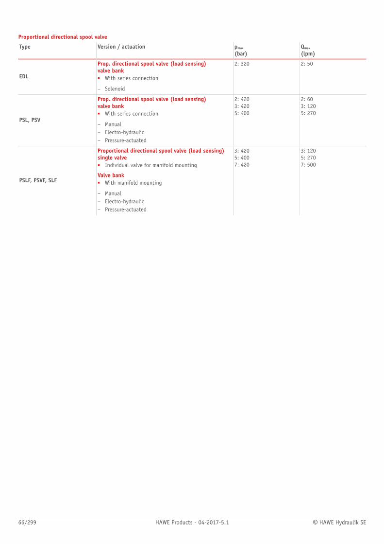
66/299 HAWE Products - 04-2017-5.1 © HAWE Hydraulik SE
Proportional directional spool valve
Type Version / actuation pmax
(bar)Qmax
(lpm)
EDL
Prop. directional spool valve (load sensing)valve bank■ With series connection
– Solenoid
2: 320 2: 50
PSL, PSV
Prop. directional spool valve (load sensing)valve bank■ With series connection
– Manual– Electro-hydraulic– Pressure-actuated
2: 4203: 4205: 400
2: 603: 1205: 270
PSLF, PSVF, SLF
Proportional directional spool valve (load sensing)single valve■ Individual valve for manifold mounting
Valve bank■ With manifold mounting
– Manual– Electro-hydraulic– Pressure-actuated
3: 4205: 4007: 420
3: 1205: 2707: 500

© HAWE Hydraulik SE HAWE Products - 04-2017-5.1 67/299
Valve combinations
Type Version / actuation pmax
(bar)Qmax
(lpm)
NSMD
Combination of directional spool valve and pressure-reducing valveAs single valve■ Individual valve for manifold mounting
As valve bank■ Valve banks are available with type BA
– electro-magnetic
2: 120 2: 80

Directional spool valves
68/299 HAWE Products - 04-2017-5.1 © HAWE Hydraulik SE
2.1 Directional spool valve type SG and SP
Directional spool valves are a type of directional valve. They control the direction of
movement and the velocity of single and double-acting hydraulic consumers.
The directional spool valve type SG is available as a single valve for pipe connection. Type
SP is available as a valve for manifold mounting. Due to the robust design the directional
spool valve type SG and SP reaches operating pressures up to 400 bar. It is of versatile use
due to different types of actuation.
Intended applications include mobile hydraulics, in particular in special vehicles, in
municipal trucks and in shipbuilding.
Features and benets:■ Sturdy design■ Suited for maritime applications■ Various actuation variants
Intended applications:■ Mining machinery■ Cranes and lifting equipment■ Ship building■ Road vehicle
Nomen-clature:
Directional spool valve
Design: Single valve for pipe connectionIndividual valve for manifold mounting
Actuation: Solenoid
Manual■ With automatic spring return■ With detent
Mechanical■ Roller head■ Pin head
Pressure-actuated■ (Individual and combined with manual
operation)■ Hydraulic■ Pneumatic
pmax: 400 bar
Qmax: 100 l/min

© HAWE Hydraulik SE HAWE Products - 04-2017-5.1 69/299
Design and order coding example
SP 1SG 3
DE 3E
- A- MD 3/24 - 120
Pressure setting pressure limiting valve [bar]
Actuation mode
Pressure limiting valve
Function ■ Parallel- or series connection■ Directional spool valves either with positive (blocked between switching positions) or
negative (slightly oating position) overlap■ SP 1 with/without check valve insert
Basic type and size Directional spool valve SG 0 to 5, SP 1, SP 3, SP 5Directional spool valves type SP for manifold mounting, sizes 1, 3, 5
Function
Basic symbol
SG SP
Individual valve for pipe connection Individual valve for manifold mounting
With pressure-limiting valve
Circuit symbol
G C D E N W R V Z U
L F H Y S X
- Circuit symbol Z, U, X: only for size 2, 3 and 5
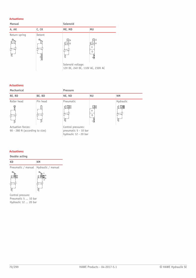
70/299 HAWE Products - 04-2017-5.1 © HAWE Hydraulik SE
Actuations:
Manual Solenoid
A, AK C, CK ME, MD MU
Return spring Detent
Solenoid voltage:12V DC, 24V DC, 110V AC, 230V AC
Actuations:
Mechanical Pressure
RE, RD BE, BD NE, ND NU NM
Roller head Pin head Pneumatic Hydraulic
Actuation forces: 90 - 280 N (according to size)
Control pressures: pneumatic 5 - 10 bar hydraulic 12 - 20 bar
Actuations:
Double acting
KD KM
Pneumatic / manual Hydraulic / manual
Control pressure: Pneumatic 5 ... 10 barHydraulic 12 ... 20 bar
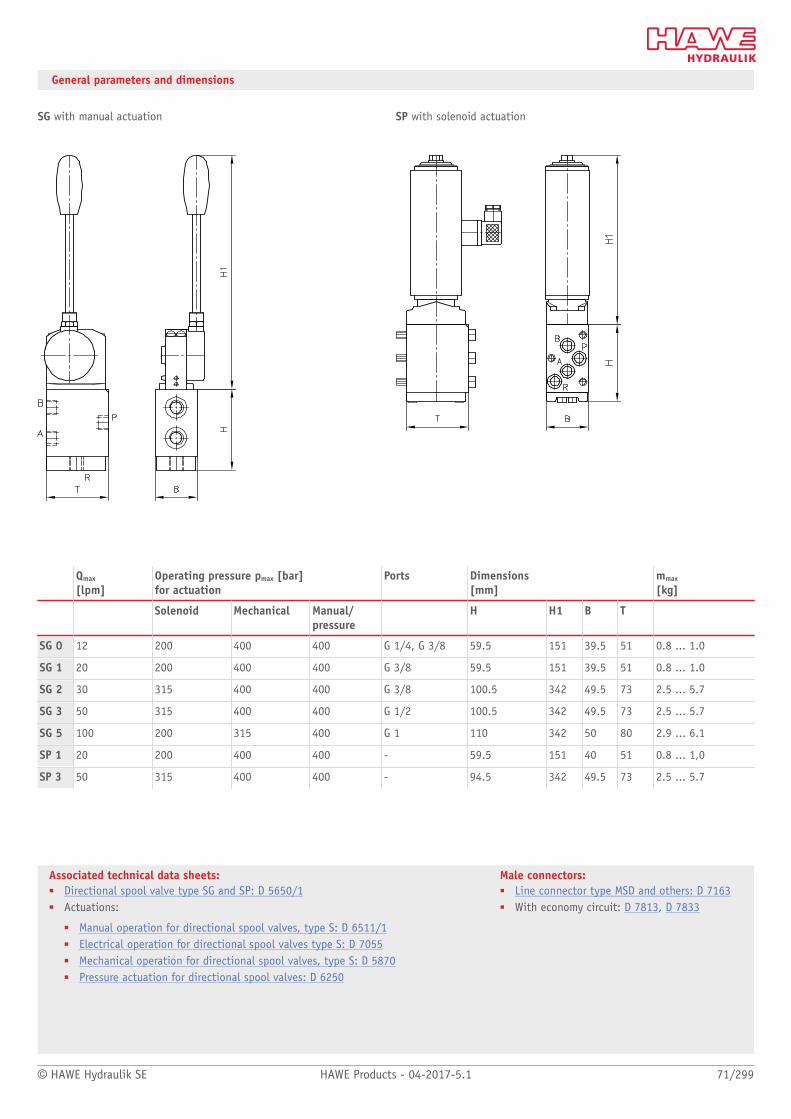
© HAWE Hydraulik SE HAWE Products - 04-2017-5.1 71/299
Associated technical data sheets:■ Directional spool valve type SG and SP: D 5650/1■ Actuations:
■ Manual operation for directional spool valves, type S: D 6511/1■ Electrical operation for directional spool valves type S: D 7055■ Mechanical operation for directional spool valves, type S: D 5870■ Pressure actuation for directional spool valves: D 6250
Male connectors:■ Line connector type MSD and others: D 7163■ With economy circuit: D 7813, D 7833
General parameters and dimensions
SG with manual actuation SP with solenoid actuation
Qmax
[lpm]Operating pressure pmax [bar] for actuation
Ports Dimensions [mm]
mmax
[kg]
Solenoid Mechanical Manual/ pressure
H H1 B T
SG 0 12 200 400 400 G 1/4, G 3/8 59.5 151 39.5 51 0.8 ... 1.0
SG 1 20 200 400 400 G 3/8 59.5 151 39.5 51 0.8 ... 1.0
SG 2 30 315 400 400 G 3/8 100.5 342 49.5 73 2.5 ... 5.7
SG 3 50 315 400 400 G 1/2 100.5 342 49.5 73 2.5 ... 5.7
SG 5 100 200 315 400 G 1 110 342 50 80 2.9 ... 6.1
SP 1 20 200 400 400 - 59.5 151 40 51 0.8 ... 1,0
SP 3 50 315 400 400 - 94.5 342 49.5 73 2.5 ... 5.7

Directional spool valves
72/299 HAWE Products - 04-2017-5.1 © HAWE Hydraulik SE
2.1 Directional spool valve type SW, SWP and NSWP
Directional spool valves are a type of directional valve. They control the direction of
movement and the velocity of single and double-acting hydraulic consumers.
The directional spool valve type NSWP and SWP is available as a manifold mounting valve.
Type NSWP is available with a nominal size 6 hole pattern (NG 6). Type SW is available as
a single valve for pipe connection. The directional spool valve type NSWP can be exibly
adapted to different control tasks by means of additional functions in the pump line and/or
on the consumer side (e.g. restrictors, restrictor check valves).
Intended applications for the directional spool valve type NSWP, SWP and SW include
industrial hydraulics, in particular machine tools.
Features and benets:■ Compact valve banks possible■ Proportional functions easy to control■ Large range of variants■ Can be combined with NG6 sub-plates (type BA2)
Intended applications:■ Machine tools■ Construction and construction materials machinery■ Offshore and marine technology■ Road vehicles
Nomen-clature:
Directional spool valve
Design: Individual valve for pipe connectionIndividual manifold mounting valveValve bank manifold mountingCombination with hydraulic power packs
Actuation: Solenoid
pmax: 315 bar
Qmax: 25 l/min
Design and order coding example
NSWP2 G /M /R / ABR1,0 /50 /G24 - 3/8
Single connection block for direct installation in the pipe G 3/8 (type NSWP andSWP2)
Voltage of the actuation solenoids 12V DC, 24V DC, 110V AC, 230V AC
■ Solenoids with various plug versions
Pressure switch or pressure gauge at A or B
Additional elements at A and/or B Restrictor check valve or orice
Additional elements at P Check valve or orice
Solenoid version ■ black/white solenoid or proportional solenoid■ Solenoid with detent■ Solenoid version conforming ATEX (pmax = 210 bar)
Function ■ Indiv. valve with check valve or orice in gallery P and/or check valve in gallery R (type SWP)■ Indiv. valve with 6/2-way function
Basic type, size Directional spool valve SW, SWP size 1 and 2 NSWP size 2, connection hole pattern NG 6 (CETOP)

© HAWE Hydraulik SE HAWE Products - 04-2017-5.1 73/299
Function
Sub-plate for pipe connection
- 1/4 S(R) - 3/8
Sub-plate with pressure limiting valve1) Sub-plate2)
1) Only for type SWP 12) Only for type NSWP and SWP 2
Valve sections
Basic symbol
Individual valve
SW SWP / NSWP
Valve sections
Circuit symbol
May be connected either in parallel or in series within a valve bank
G D E O C3) N B W K Q R3) U3)
Only connected in series within a valve bank (only type SW1) Spool for proportional adjustment
L F H S Y G D
3) Only for type SWR 1

74/299 HAWE Products - 04-2017-5.1 © HAWE Hydraulik SE
General parameters and dimensions
SW SWP/NSWP2
1 Single connection block
2 Pressure-limiting valve
Qmax
[lpm]pmax
[bar]Ports Dimensions
[mm]m[kg]
H B T Individualdirectional spoolvalve
Sub-plate
SW/SWP 1 12 315 G 1/4 77 ... 90 40 40 ... 44 1.1 ... 1.5 0.6 ... 0.7
SW/SWP 2 G 3/8, G 1/4
NSWP2
25 315
NG 6
78 ...- 82.5 60 ... 70 40 ... 45 1.1 ... 2.4 0.8
Circuit example 1:
BA2-A5 -NSWP2G/M/03/NZP16V/PQ20/0 -NSWP2G/M/R/B1,0 -NSWP2K/M/20/0 -NSWP2K/M/20/NZP16Q33/0 -2-L24
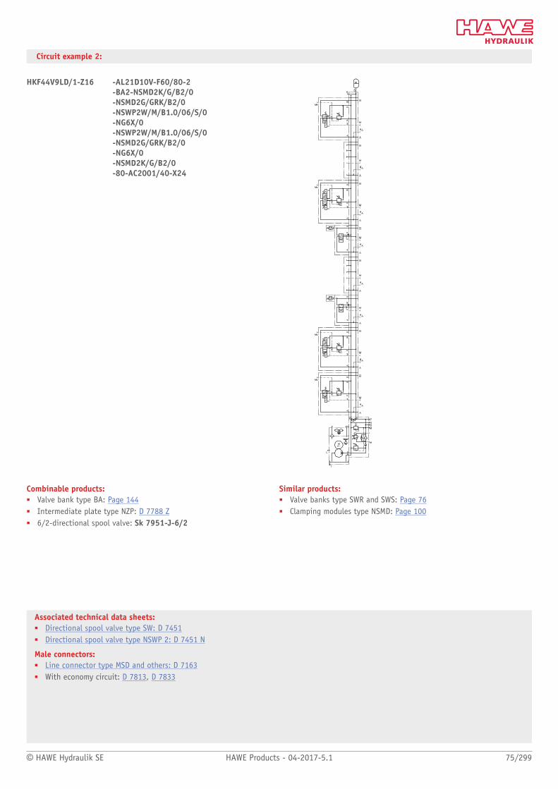
© HAWE Hydraulik SE HAWE Products - 04-2017-5.1 75/299
Associated technical data sheets:■ Directional spool valve type SW: D 7451■ Directional spool valve type NSWP 2: D 7451 N
Male connectors:■ Line connector type MSD and others: D 7163■ With economy circuit: D 7813, D 7833
Circuit example 2:
HKF44V9LD/1-Z16 -AL21D10V-F60/80-2-BA2-NSMD2K/G/B2/0 -NSMD2G/GRK/B2/0-NSWP2W/M/B1.0/06/S/0-NG6X/0-NSWP2W/M/B1.0/06/S/0-NSMD2G/GRK/B2/0-NG6X/0-NSMD2K/G/B2/0-80-AC2001/40-X24
Combinable products:■ Valve bank type BA: Page 144■ Intermediate plate type NZP: D 7788 Z■ 6/2-directional spool valve: Sk 7951-J-6/2
Similar products:■ Valve banks type SWR and SWS: Page 76■ Clamping modules type NSMD: Page 100

Directional spool valve
76/299 HAWE Products - 04-2017-5.1 © HAWE Hydraulik SE
2.1 Directional spool valve bank type SWR and SWS
Directional spool valves are a type of directional valve. They control the direction of
movement and the velocity of single and double-acting hydraulic consumers.
The directional spool valve bank type SWS is available with series connection. The
consumers can be operated with on-off or proportional control. Versions are available
for usage in potentially explosive atmospheres. By means of additional functions in the
pump line, in the intermediate plates (longitudinal and sandwich valve combination) and
ancillary blocks the directional spool valve bank can be exibly adapted to different control
tasks.
Intended applications include mobile hydraulics, in particular civil engineering, agricultural
engineering and material handling.
Features and benets:■ Can be combined for forklift trucks with lifting modules■ Suitable for constant pressure systems■ Proportional movements can also be controlled independently of the load■ Extensive range of ancillary blocks■ Compact and extremely space-saving dimensions
Intended applications:■ Material handling■ Wind turbines■ Construction and construction materials■ Handling and assembly techn.■ Municipal trucks
Nomen-clature:
Directional spool valve
Design: Valve bankCombination with hydraulic power packs
Actuation: Solenoid
pmax: 315 bar
Qmax: 25 l/min
Design and order coding example
SWR1 A-6/230 - GG - 1 - G24
Solenoid voltage 12V DC, 24V DC, 110V AC, 230V AC
■ Solenoids with various plug versions
End plate ■ Additional ports P and/or R (P can be blocked)■ Idle circulation valve (ON/OFF, proportional)■ End spool valve
Valve sections ■ Directional spool valve■ Additional options for the valve sections:
■ Options upstream (orice, ow controller)■ Consumer-side additional functions in ancillary block, e.g. double check valves, shock valves (load-
holding valves etc.)
Connection block/adapter plate ■ Pressure limiting valve (for pipe connection)■ Idle circulation valve■ 3-way ow controller
Basic type, size Type SWR 1 and SWS 2

© HAWE Hydraulik SE HAWE Products - 04-2017-5.1 77/299
Function
Connection blocks:
A 6 F/D
With xed pressure limiting valve (for pipe connection)
For direct mounting onto hydraulic power packs(type KA, HC, MP, HK)
Valve sections:
Basic symbol Symbol
SWR 1 SWS 2 G D E O C N B W K Q R U
1 Ancillary block with additional
function
(on the consumer side)
2 Actuation
3 Additional function
(on the pump side)
Spool valves suited for prop. actuation
G D
Additional versions for valve sections:■ b/w solenoids with stroke limitation■ prop. solenoids with stroke limitation■ solenoids also available in ATEX-compliant version (pmax = 210 bar)
End plates (SWR 1/SWS 2):
Series With circulation valve With lockable pump output
Ancillary block type SWS 2 with additional functions (consumer side):
Releasable check valve Shock valve Sequence valve Over center valve
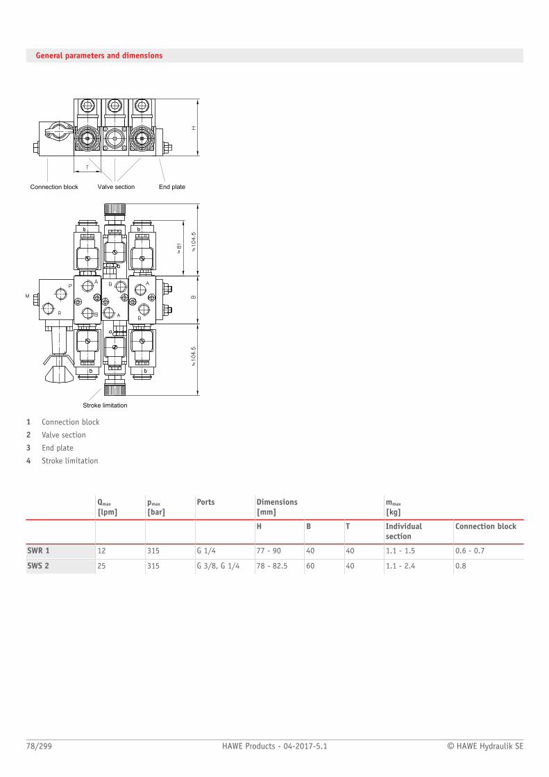
78/299 HAWE Products - 04-2017-5.1 © HAWE Hydraulik SE
General parameters and dimensions
Connection block Valve section End plate
Stroke limitation
1 Connection block
2 Valve section
3 End plate
4 Stroke limitation
Qmax
[lpm]pmax
[bar]Ports Dimensions
[mm]mmax
[kg]
H B T Individualsection
Connection block
SWR 1 12 315 G 1/4 77 - 90 40 40 1.1 - 1.5 0.6 - 0.7
SWS 2 25 315 G 3/8, G 1/4 78 - 82.5 60 40 1.1 - 2.4 0.8

© HAWE Hydraulik SE HAWE Products - 04-2017-5.1 79/299
Associated technical data sheets:■ Directional spool valve type SW: D 7451■ Directional spool valve bank type SWS: D 7951
Suited products for combination:■ Pressure switches type DG3.., DG5.E: Page 262
Similar products:■ Proportional directional spool valve type EDL: Page 82
Suitable male connectors:■ Line connector type MSD and others: D 7163■ With economy circuit: D 7813, D 7833/1■ Proportional amplifier type EV2S: Page 274
Circuit example:
SWS 2 A 7/200
Valve bank type SWS, size 2, connection block with pressure-limiting valve (manually adjustable, set to 200 bar)
- G/M/2/2 RH
1. Valve section with circuit symbol G with solenoid actuation, no additional function in P gallery, with releasable check valves for A and B in the
ancillary block
- G 10/MPF/DW/2 AL B 7/180 BLC 4/140
2. Valve section with circuit symbol G and proportional spool, max. ow rate A and B with 10 lpm, proportional solenoid MP with stroke limitation
for A and B, pressure compensator in P gallery of the basic block (DW), ancillary block with load-holding valve for A (set to 180 bar) and for B (set
to 140 bar)
- E/M/R/2 AN100 BN 100-1-G 24
3. Valve section with circuit symbol E and solenoid actuation, a check valve in the P gallery, ancillary block featuring shock and servo-suction
valves for ports A and B (set to 100 bar), standard end plate, solenoid voltage 24V DC

Directional spool valve
80/299 HAWE Products - 04-2017-5.1 © HAWE Hydraulik SE
2.1 Directional spool valve type HSF
Directional spool valves are a type of directional valve. They control the direction of
movement and the velocity of single and double-acting hydraulic consumers.
The directional spool valve type HSF is a manifold mounting valve. Due to the robust
design, it reaches operating pressures of up to 400 bar.
Adjustable threaded throttles are used to adjust the response time. Harsh switching
operations and decompression surges, particularly in the event of high pressure and large
consumer volumes, can be avoided this way.
Features and benets:■ Smooth switching for large ow rate■ Suitable for high pressures due to steel housing
Intended applications:■ Mining machinery (incl. oil production)■ Cranes and lifting equipment■ Construction and construction materials machinery■ Material handling (industrial trucks, etc.)
Nomen-clature:
Directional spool valve
Design: Individual valve for manifold mounting
Actuation: Electro-hydraulicHydraulic
pmax: 400 bar
Qmax: 160 l/min
Design and order coding example
HSF4 /C321 - L - 1 - G24 - 300
Pressure setting pressure limiting valve [bar]
Solenoid voltage 12V DC, 24V DC, 98V DC, 205V DC, 110V AC, 230V AC
End plate Internal or external control oil return
Valve sections With/without adjustable switching speed
Connection block ■ With/without pressure limiting valve (Fixed or manually adjustable)■ Internal or external control oil supply (max. 160 bar)
Basic type and size Type HSF: Manifold mounting

© HAWE Hydraulik SE HAWE Products - 04-2017-5.1 81/299
Associated technical data sheets::■ Directional spool valve type PSL and PSV: D 7700-2; D 7700-3■ Directional spool valve type HSF: D 7493 E■ Directional spool valve type HSL: D 7493 L
Male connectors:■ Line connector type MSD and others: D 7163■ With economy circuit: D 7813, D 7833/1
Function
Valve sections:
Basic symbol Symbol
HSF G D E C W B L H F
Manifold mounting valve All ow pattern symbols also available with adjustable response time
General parameters and dimensions
Qmax
[l/min]pmax
[bar]Dimensions[mm]
m [kg]
H B T
HSF 3 80 400 137 59 126 2,8
HSF 4 160 400 157 70 184 5

Directional spool valve
82/299 HAWE Products - 04-2017-5.1 © HAWE Hydraulik SE
2.1 Proportional directional spool valve type EDL
Proportional directional spool valves are a type of directional valve. They control the
direction of movement and the velocity of individual or multiple hydraulic consumers
actuated simultaneously. Control is independent of the load and continuous.
The directional spool valve type EDL with series connection is actuated directly. The ow
rates for the individual consumers can be individually adjusted. The proportional direction-
al spool valve can be exibly adapted to different control tasks by means of additional
functions in the intermediate plates and ancillary blocks.
The directional spool valve type EDL can be combined directly with the proportional
directional spool valve type PSL and PSV in size 2 and is therefore suitable for constant and
variable pump systems. It is used in mobile hydraulics, in particular in civil engineering
and agricultural engineering.
Features and benets:■ One valve for different control functions and small ow quantities■ Energy-saving closed-centre systems■ Compact and lightweight design■ Modular system can be directly combined with type PSL/PSV-2
Intended applications:■ Construction and construction materials machinery■ Cranes and lifting equipment■ Machines for forestry and agricultural purposes■ Municipal trucks
Nomenclature: DirectlyProp. directional spool valves as per load-sensing principle
Version: Valve bank in series connection
Actuation: solenoid-actuated
pmax: 320 bar
Qmax. consumer: 48 l/min
Qpu max: 100 l/min
Design and order coding example
EDL - DA2 L 40/25 E /2 - G24
Solenoid voltage 12V DC, 24V DC
■ Actuated via prop. amplifier or PLVC
Ancillary blocks
Confirmation Type E, EI
Volumetric ow Volumetric ow indicator, side A, B (3...40)
Spool Type L, H
Spool block Section with inow controller
Basic type Type EDL: directly actuated proportional directional spool valve
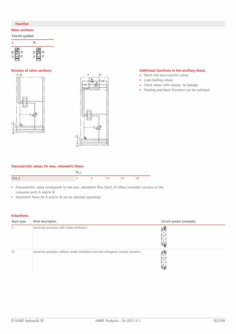
© HAWE Hydraulik SE HAWE Products - 04-2017-5.1 83/299
Function
Valve sections:
Circuit symbol
L H
Versions of valve sections: Additional functions in the ancillary block:■ Shock and servo-suction valves■ Load-holding valves■ Check valves with release, no leakage■ Floating and block functions can be switched
Characteristic values for max. volumetric ows:
QA, B
Size 2 3 6 10 25 40
■ Characteristic value corresponds to the max. volumetric ow [lpm] of inow controller versions at theconsumer ports A and/or B
■ Volumetric ows for A and/or B can be selected separately
Actuations:
Basic type Brief description Circuit symbol (example)
E electrical actuation with stroke limitation
EI electrical actuation without stroke limitation and with emergency manual actuation

84/299 HAWE Products - 04-2017-5.1 © HAWE Hydraulik SE
General parameters and dimensions
PSL/EDL
1 Connection block
2 Valve section
3 End plate
Flow[lpm]
Oper.pressure[bar]
Ports Dimensions[mm]
m[kg]
Qmax Qpu max pmax P, R A, B H H1 B T Per valvesection1)
EDL 3 ... 40 80 320 G 1/2, 3/4-16 UNF-2B
G 3/8, 3/4-16 UNF-2B
241 80 40 64 1.8 ... 2.9
1) Dep. on actuation and additional functions

© HAWE Hydraulik SE HAWE Products - 04-2017-5.1 85/299
Associated technical data sheets:■ Proportional directional spool valve type EDL: D 8086■ Proportional directional spool valve, type PSL and PSV size 2: D 7700-2■ Proportional directional spool valve, type PSL, PSM and PSV size 3: D 7700-3■ Proportional directional spool valve, type PSL, PSM and PSV size 5: D 7700-5■ Connection block type HMPL and HMPV for proportional directional spool valve: D 7700 H
Circuit example:
PSV 3-2
- DA2L40/25/E/2
- DA2L25/16/E/24l-0-A4/210-Bl0-B4/210
- E4-G24

Directional spool valve
86/299 HAWE Products - 04-2017-5.1 © HAWE Hydraulik SE
2.1 Directional spool valve bank type DL
Throttling directional spool valves are a type of directional valve. They continuously and
manually meter the ow rate in hydraulic systems with single and double-acting consumers.
The throttling directional spool valve type DL inuences the speed of the consumer by
throttling the pump circulation via a parallel circuit (bypass control). The close t of
the spool in the throttling directional spool valve means that the leakage is limited to a
minimum for lifting functions.
The throttling directional spool valve type DL is suitable for applications in material
handling and for lifting equipment.
Features and benets:■ Compact design with up to 10 segments■ Various actuation variants for manual actuation■ Simple pressure reductions in downstream sections using intermediate plates■ Combinations possible for controlling lifting devices
Intended applications:■ Material handling (industrial trucks, etc.)■ Machines for agricultural and forestry purposes■ Construction and construction materials machinery■ Road vehicle
Nomen-clature:
Throttling directional spool valve
Design: Valve bank design with integrated bypasspump circulation control
Actuation: Manual■ Return spring, detent
pmax: 315
Qmax: 90
Design and order coding example
DL3 1 - 3 - GGD - B/E1 - 2 - 210
Pressure specification [bar]
End plate
Actuation, mounting
Valve sections ■ Directional spool valve■ Valve section options:
■ Intermediate plate with pressure-limiting valve for all downstream valve sections■ Additional functions on the consumer side in the ancillary block (e.g. double check valves, shock
valves, load-holding valves etc.) (size 3)
Port size G 1/4, G 3/8, G 1/2 (BSPP)
Connection block ■ With/without pressure limiting valve■ With shock valve
Basic type, size Type DL, sizes 1 to 4
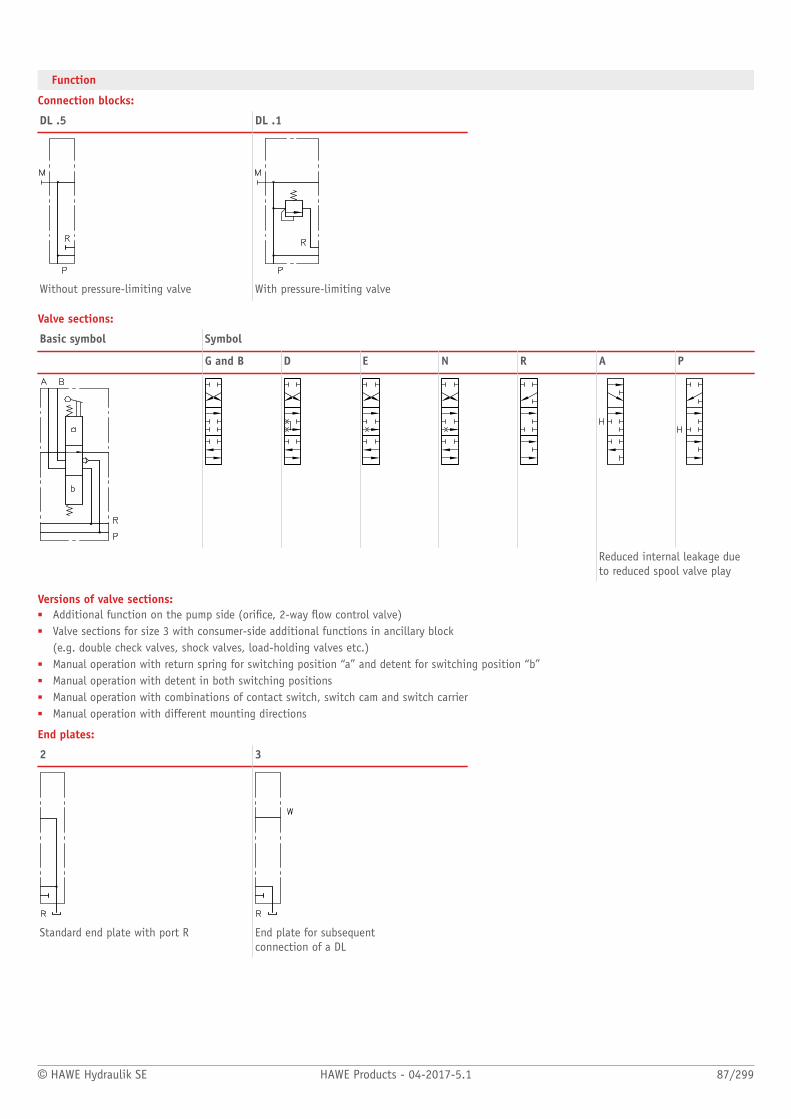
© HAWE Hydraulik SE HAWE Products - 04-2017-5.1 87/299
Function
Connection blocks:
DL .5 DL .1
Without pressure-limiting valve With pressure-limiting valve
Valve sections:
Basic symbol Symbol
G and B D E N R A P
Reduced internal leakage dueto reduced spool valve play
Versions of valve sections:■ Additional function on the pump side (orice, 2-way ow control valve)■ Valve sections for size 3 with consumer-side additional functions in ancillary block
(e.g. double check valves, shock valves, load-holding valves etc.)■ Manual operation with return spring for switching position “a” and detent for switching position “b”■ Manual operation with detent in both switching positions■ Manual operation with combinations of contact switch, switch cam and switch carrier■ Manual operation with different mounting directions
End plates:
2 3
Standard end plate with port R End plate for subsequent connection of a DL

88/299 HAWE Products - 04-2017-5.1 © HAWE Hydraulik SE
General parameters and dimensions
Connection blockValve sections
End plate
1 Connection block
2 Valve section
3 End plate
Qmax
[lpm]pmax
[bar]Ports Dimensions
[mm]m[kg]
Characteris-tic value
A, B H, P, R H B T
DL 1 12 ... 16 315 1 G 1/4 G 1/4 192 31,5 45 0,5
1 G 1/4 G 3/8DL 2 20 ... 30 315
2 G 3/8 G 3/8
278 34,5 50 0,85
2 G 3/8 G 1/2DL 3 30 ... 60 250
3 G 1/2 G 1/2
351 39,5 60 1,4
DL 4 90 250 3 G 1/2 G 3/4 368 39,5 70 1,8
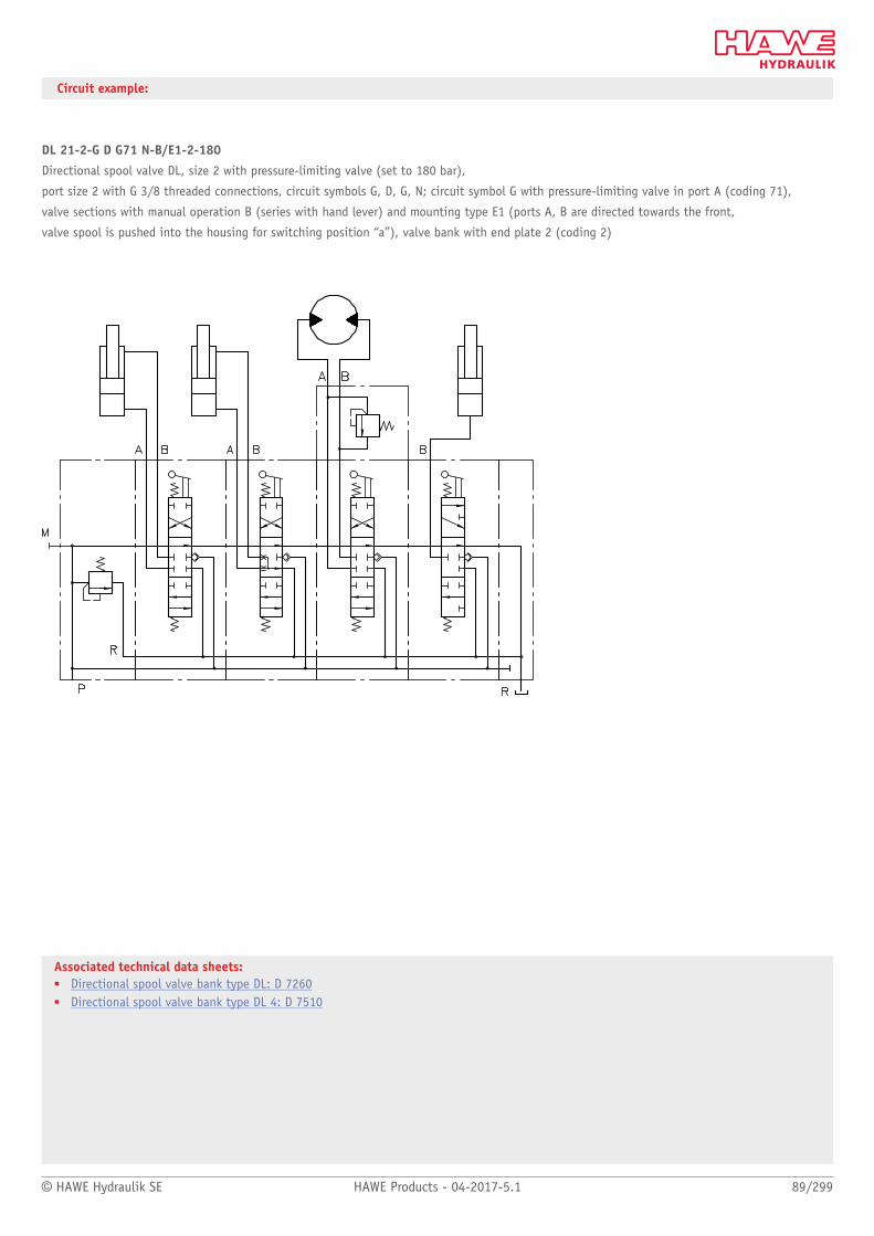
© HAWE Hydraulik SE HAWE Products - 04-2017-5.1 89/299
Associated technical data sheets:■ Directional spool valve bank type DL: D 7260■ Directional spool valve bank type DL 4: D 7510
Circuit example:
DL 21-2-G D G71 N-B/E1-2-180
Directional spool valve DL, size 2 with pressure-limiting valve (set to 180 bar),
port size 2 with G 3/8 threaded connections, circuit symbols G, D, G, N; circuit symbol G with pressure-limiting valve in port A (coding 71),
valve sections with manual operation B (series with hand lever) and mounting type E1 (ports A, B are directed towards the front,
valve spool is pushed into the housing for switching position “a”), valve bank with end plate 2 (coding 2)

Directional spool valves
90/299 HAWE Products - 04-2017-5.1 © HAWE Hydraulik SE
2.1 Proportional directional spool valves type PSL and PSV
Proportional directional spool valves are a type of directional valve. They control the
direction of movement and the velocity of individual or multiple hydraulic consumers
actuated simultaneously. Control is independent of the load and continuous.
The proportional directional spool valve type PSL is suitable for constant pump systems
and type PSV for variable pump systems with a pressure/ow controller. The volumetric
ows and load pressures for the individual consumers can be individually adjusted. The
proportional directional spool valve type PSL and PSV can be adapted to various control
tasks, e.g. for safety functions. All sizes can be combined with each other.
The proportional directional spool valve type PSL and PSV is used in mobile hydraulics,
in particular in crane and lifting equipment, construction and mining machinery, drilling
equipment as well as in offshore and marine technology.
Features and benets:■ One product for various control functions and volume quantities■ Energy-saving Closed-Center systems■ Compact and lightweight design■ Modular system with wide range of design variants
Intended applications:■ Construction/construction material machinery■ Mining machinery (incl. oil production)■ Cranes and lifting equipment■ Machines for forestry and agricultural purposes■ Municipal machinery
Nomenclature: Prop. directional spool valves as per load-sensing principle
Version: Valve bank in series connection
Actuation: Manual■ Return spring■ Detent
Electro-hydraulic, pressure-actuated■ Hydraulic■ Pneumatic
pmax: 400 bar
Qmax. consumer: 240 l/min
Qpu max: 300 lpm
Design and order coding example
PSL41F /380 - 3 - A2J40/40/EA/3 - E4 - G24
Solenoid voltage 12V DC, 24V DC
■ Actuated via prop. amplifier or PLVC■ Solenoids with various plug versions■ Explosion proof solenoids
End plates
Valve sections with actuation
Size
Connection block ■ Various connection threads■ Pressure limiting valve (piloted main pressure limiting valve)■ Suited for both constant and variable displacement pump systems (type PSM)
Basic type Type PSL (hydraulic oil supply by constant pump), sizes 2, 3 and 5Type PSV (hydraulic oil supply by variable pump), sizes 2, 3 and 5Type HMPL (hydraulic oil supply by constant pump) for industrial trucks, sizes 2 and 3Type HMPV (hydraulic oil supply by variable pump) for industrial trucks, sizes 2 and 3

© HAWE Hydraulik SE HAWE Products - 04-2017-5.1 91/299
Function
Connection blocks:
PSL PSV HMPL (HMPV)
1 Pilot pressure regulating valve
2 2/2-way solenoid valve
Connection block for constant pump systemswith integrated 3-way controller, pressure-limiting valve and LS shutdown
Connection block for variable pump systems withor without pressure-limiting valve
Connection block for constant delivery pumpwith incorporated proportional seated valve forlifting and lowering
Additional versions of connection blocks:■ 2/2-way solenoid valve for randomly switching the pump direction■ Additional damping option of the 3-way/pump controller■ Additional isolation valve to minimise the pump direction resistance■ Version with additional shut-off valve for the pump line, can be switched randomly■ Proportionally adjustable pressure limitation
Valve sections:
Basic symbols Circuit symbol
L M F H J B R O G

92/299 HAWE Products - 04-2017-5.1 © HAWE Hydraulik SE
Versions of valve sections:■ Load pressure signal outputs at A, B; A and B together■ 3/3 directional spool valve with 2-way input and output controller■ Version with and without 2-way inow controller■ Function deactivation feature■ Secondary pressure-limiting valves (can be selected for A
and/or B)■ Prop. Pressure limitation of individual functions■ Version with ancillary blocks■ Intermediate plates for various additional functions■ Combination of various sizes possible in one valve bank■ Version with EX solenoid for use in potentially
explosive areas■ Version with explosion-proof, intrinsically safe
magnets for mining applications■ Version with CAN actuation
Additional functions in the ancillary block:■ Shock and servo-suction valves■ Load-holding valves■ Differential circuits■ Check valves with release, zero-leakage■ Floating and block functions can be switched■ Proportional seated valves in accordance with D 7490/1 for lifting
and lowering functions with plunger cylinders
Characteristic values for max. volumetric ows:
QA, B
Size 2 3 6 10 16 25 40
Size 3 3 6 10 16 25 40 63 80
Size 5 16 25 40 63 80 120 160
■ Characteristic value corresponds to the max. volumetric ow [lpm] of inow controller versions at theconsumer ports A and/or B
■ Volumetric ows for A and/or B can be selected separately■ Increasing the control pressure enables 60 lpm (size 2), 120 lpm (size 3)
and 240 lpm (size 5) per consumer port side.■ Version with 2-way inow controller and check valve function, or damping elements

© HAWE Hydraulik SE HAWE Products - 04-2017-5.1 93/299
Actuations:
Basic type Brief description Circuit symbol (example)
A Manual actuation
C Detent (continuous)
EEA
Electro-hydraulic actuation in combination with manual operation
EI CANEA CAN
CAN: Actuation variant with CAN control in combination with manual operation
H, PHA, PA
Hydraulic and pneumatic actuation in combination with manual operation
HEA Combination of H, E and A actuation
Combination of electro-hydraulic and manual actuation
Intermediate plates:■ Electrically or hydraulically actuated shut-off valve for all downstream consumers■ With pressure-limiting valve to limit the operation pressure of all downstream valves■ For random switchable reduction of the volumetric ow of all downstream consumers■ Priority module, size 3
End plates:
E1 E2
Standard end plate With additional Y-port for LS-input signal
Additional versions of end plates:■ End plate with internal leakage oil routing (no T gallery)■ End plates with additional P and R gallery■ Adapter plate to combine size 5 and 3 (coding ZPL 53), size 5 and 2
(coding ZPL 52) and size 3 and 2 (coding ZPL 32)■ End plate with integrated connection block function for dual-pump/dual-circuit systems

94/299 HAWE Products - 04-2017-5.1 © HAWE Hydraulik SE
General parameters and dimensions
Valve section
End plate
Connection block
1 Connection block
2 Valve section
3 End plate
Flow[lpm]
Oper.pressure[bar]
Ports Dimensions[mm]
m[kg]
Qmax Qpu max pmax P, R A, B H H1 B T Per valvesection1)
PSL/PSV 2 3 ... 54 80 420 G 1/2, 3/4-16 UNF-2B
G 3/8, 3/4-16 UNF-2B
272 150 40 60 1.8 ... 2.9
PSL/PSV 3 3 ... 120 200 420 G 1/2, G 3/4, G 1, 1 1/16-12 UNF-2B
G 1/2, G 3/4, 7/8-14 UNF-2B
364 195 50 80 3.3 ... 4.1
PSL/PSV 5 16 ... 240 300 400 G 1, G 1 1/4, 1 5/8-12 UN-2B
G 1, 5/16-12 UNF-2B
400 224 62.5 100 3.7 ... 4.5
1) Dep. on actuation and additional functions

© HAWE Hydraulik SE HAWE Products - 04-2017-5.1 95/299
Associated technical data sheets:■ Proportional directional spool valve, type PSL and PSV size 2:
D 7700-2■ Proportional directional spool valve, type PSL, PSM and PSV size
3: D 7700-3■ Proportional directional spool valve, type PSL, PSM and PSV size
5: D 7700-5■ Actuation for proportional directional spool valves type PSL/PSV:
D 7700 CAN
Associated technical data sheets:■ Connection block type HMPL and HMPV for proportional direction-
al spool valve: D 7700 H■ Proportional directional spool valve type EDL: D 8086
Circuit example:
PSL 41/350 - 3 -32 J 25/16 A300 F1/EA -42 O 80/63 C250/EA -42 J 63/63 A100 B120 F3/EA -31 L 40/16/A
- E2 - G24
Type PSL valve bank for constant pumpsystemsConnection block:
– Coding for thread size (here 4 = G 3/4)
– Coding for pilot pressure-reducing valve(here 1)
– Coding for set pressure at pressure-limiting valve (here 350 bar)
Size: 3
1. Valve section: (exemplary for all subsequent valve sections):
– Directional spool valve block with coding for consumer connection size (here3 = G 1/2)
– Coding for the type of directional spool valve block (here 2)– Circuit symbol (here J)– Coding for max. consumer volumetric ow to ports A and B (here 25 and 16
lpm)– Coding of additional functions (here A 300; secondary pressure-limiting valve
at port A set to 300 bar, function deactivated for port A (here F1))– Coding for actuation type (here EA)
End plate:
– Coding for end plate (here E2)– Coding for 24V DC solenoid
voltage (here G24)
Products suitable for combination:■ Load-holding valves type LHT, LHDV: Page 198■ Joystick: Proportional pressure-reducing valve type KFB 01: D 6600-01
Additional electrical components:■ Proportional amplifier:Page 272■ Programmable logic valve control type PLVC: Page 276■ CAN node type CAN-IO: Page 276■ Other electronic accessories See "Electronics"
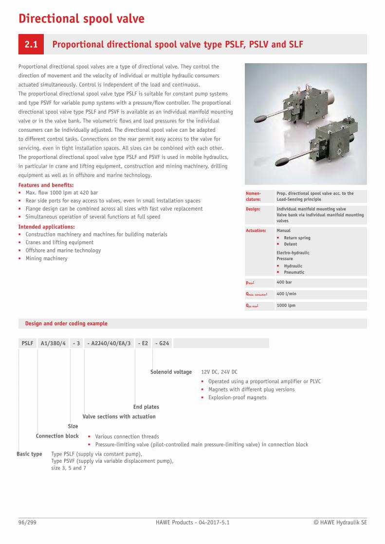
Directional spool valve
96/299 HAWE Products - 04-2017-5.1 © HAWE Hydraulik SE
2.1 Proportional directional spool valve type PSLF, PSLV and SLF
Proportional directional spool valves are a type of directional valve. They control the
direction of movement and the velocity of individual or multiple hydraulic consumers
actuated simultaneously. Control is independent of the load and continuous.
The proportional directional spool valve type PSLF is suitable for constant pump systems
and type PSVF for variable pump systems with a pressure/ow controller. The proportional
directional spool valve type PSLF and PSVF is available as an individual manifold mounting
valve or in the valve bank. The volumetric ows and load pressures for the individual
consumers can be individually adjusted. The directional spool valve can be adapted
to different control tasks. Connections on the rear permit easy access to the valve for
servicing, even in tight installation spaces. All sizes can be combined with each other.
The proportional directional spool valve type PSLF and PSVF is used in mobile hydraulics,
in particular in crane and lifting equipment, construction and mining machinery, drilling
equipment as well as in offshore and marine technology.
Features and benets:■ Max. ow 1000 lpm at 420 bar■ Rear side ports for easy access to valves, even in small installation spaces■ Flange design can be combined across all sizes with fast valve replacement■ Simultaneous operation of several functions at full speed
Intended applications:■ Construction machinery and machines for building materials■ Cranes and lifting equipment■ Offshore and marine technology■ Mining machinery
Nomen-clature:
Prop. directional spool valve acc. to the Load-Sensing principle
Design: Individual manifold mounting valveValve bank via individual manifold mountingvalves
Actuation: Manual
■ Return spring■ Detent
Electro-hydraulicPressure
■ Hydraulic■ Pneumatic
pmax: 400 bar
Qmax. consumer: 400 l/min
Qpu max: 1000 lpm
Design and order coding example
PSLF A1/380/4 - 3 - A2J40/40/EA/3 - E2 - G24
Solenoid voltage 12V DC, 24V DC
■ Operated using a proportional amplifier or PLVC■ Magnets with different plug versions■ Explosion-proof magnets
End plates
Valve sections with actuation
Size
Connection block ■ Various connection threads■ Pressure-limiting valve (pilot-controlled main pressure-limiting valve) in connection block
Basic type Type PSLF (supply via constant pump), Type PSVF (supply via variable displacement pump),size 3, 5 and 7

© HAWE Hydraulik SE HAWE Products - 04-2017-5.1 97/299
Function
Connection blocks:
PSLF PSVF
1 Pilot pressure valve
2 2/2-way solenoid valve
Connection block for constant pump systems with integrated 3-waycontroller, pressure-limiting valve and LS shutdown
Connection block for variable pump systems with and without pressure-limiting valve
Additional versions of connection blocks:■ 2/2-way solenoid actuated directional valve for arbitrary idle pump circulation■ Additional damping of the 3-way ow controller or pump controller■ Proportional adjustable pressure limitation
Valve sections:
Basic symbol Circuit symbol
L M F H J B R O G

98/299 HAWE Products - 04-2017-5.1 © HAWE Hydraulik SE
Versions of valve sections:■ Load-signal outlets at A, B; A and B together■ Version with and without 2-way inow controller■ Function deactivation■ Secondary pressure-limiting valves (can be individually selected for A and/or B)■ Proportional pressure limitation of the individual functions■ Sub-plates with different additional functions■ Sub-plates for ancillary blocks■ Sub-plates for combining various sizes■ Combination of various sizes in one valve bank possible■ Version with EX solenoid for use in potentially explosive areas■ Version with explosion-proof, intrinsically safe solenoids for mining applications
Key gures for max. ow rates:
QA, B
Size 3 3 6 10 16 25 40 63 80
Size 5 16 25 40 63 80 120 160
Size 7 120 160 250 320 400
■ Key gure represents the max. ow rate (lpm) at consumer ports A or B for version with inow controller■ Flow rates for A and/or B can be selected individually■ Increasing the control pressure means that 60 lpm (size 2), 120 lpm (size 3), 240 lpm (size 5) and 500 lpm (size 7) is possible per consumer
port side.■ Versions with 2-way inow controller and check valve function
Actuations:
Basic type Brief description Circuit symbol (example)
A Manual operation
C Detent (stepless)
EEA
Electro-hydraulic actuation in combination with manual operation
EI CANEA CAN
CAN: Actuation variant with CAN control in combination with manual operation
H, PHA, PA
Hydraulic and pneumatic actuation in combination with manual operation
HEA Combination of H, E and A actuation
Combination of electro-hydraulic and manual operation
End plates:
E1 E2
Standard end plate Additional Y-input for LS control signal
Additional versions of end plates:■ End plate with internal leakage oil routing (no tank connection)■ End plates with additional R port■ Adapter plate for combining size 5 and 3 (coding ZPL 53)

© HAWE Hydraulik SE HAWE Products - 04-2017-5.1 99/299
Associated technical data sheets:■ Proportional directional spool valve type PSLF, PSVF and SLF:
D 7700-F■ Proportional directional spool valve banks type PSLF and PSVF size
7: D 7700-7F■ Actuation for proportional directional spool valves type PSL/PSV:
D 7700 CAN
General parameters and dimensions
Connection blockValve sections
End plate
1 Connection block
2 Valve sections
3 End plate
Flow[lpm]
Oper.pressure[bar]
Ports Dimensions[mm]
m[kg]
Qmax QPU max pmax P, R A, B H1 B T T1 1) 2)
PSLF/PSVF 3 3 - 120 200 420 G 3/4, 1 1/16-12 UN-2B
G 1/2, G 3/4, 7/8-14 UNF-2B
195 50 80 50 3.3 ... 4.1 6.6 ... 7.6
PSLF/PSVF 5 16 - 210 350 400 G 1, G 1 1/4, SAE 1 1/2"
G 1, SAE 1"
224 62.5 100 100 3.7 ... 4.5 10.9 ... 16.3
PSLF/PSVF 7 120 - 500 1000 400 G 1 1/2, SAE 1 1/2"
G 1 1/4, SAE 1 1/4"
305 106 101 95 13 23
1) Per valve section depending on actuation and additional functions2) Per valve section complete with sub-plate
Products suitable for combination:■ Load-holding valves type LHT, LHDV: Page 198■ Joystick: Proportional pressure-reducing valve type KFB 01: D 6600-01
Additional electrical components:■ Proportional amplifier:Page 272■ Programmable logic valve control type PLVC: Page 276■ CAN node type CAN-IO: Page 276■ Other electronic accessories See "Electronics"

Directional spool valve
100/299 HAWE Products - 04-2017-5.1 © HAWE Hydraulik SE
2.1 Clamping module type NSMD
Clamping modules combine a directional spool valve, pressure reducing valve and pressure
switch.
The clamping module type NSMD has the standard connection pattern nominal size NG
6. It controls power-driven clamping devices, e.g. hydraulically-driven hollow and solid
clamping cylinders for automatic lathes. It regulates the clamping pressure and monitors
it. The clamping pressure is adjusted at the downstream pressure switch using a manual,
mechanical or electrically-proportional adjustment device. A special safety circuit monitors
the switching position of the valve.
Throttling options in the spool end position and/or rapid and creeping movements are
possible as an additional function for one or both consumer ports. The clamping module
type NSMD can be combined with other valves as a valve bank type BA to form a valve
block.
Features and benets:■ Directional valve, pressure-reducing valve and pressure switch in one device■ Adjustment of pressure-reducing valve and pressure switch with an adjustment device
(manual or electro-proportional)■ The controlled pressure is picked up directly at the consumer port■ Valve with connection pattern in accordance with DIN 24340-A6
Intended applications:■ Machine tools (cutting)■ Machine tools (non-cutting) - forming and cutting■ Handling and mounting technology (industrial robots, etc.)
Nomen-clature:
Valve combination consisting of:
■ Directional spool valve (4/3-, 4/2-wayfunction)
■ Pressure reducing valve with trackedpressure switch
Design: Individual valve for manifold mounting(Valve banks with sub-plates type BA areavailable)
Actuation: Solenoid
pmax: 120 bar
Qmax: 25 l/min
Design and order coding example
NSMD 2 D1 /MDA /GRK - G24
Solenoid voltage 12V DC, 24V DC, 110V AC, 230V ACSolenoids with various plug versions
Clamping pressure adjustment, pressure range, switching ow rate
■ Slotted head screw + hexagon nut■ Wing screw + wing nut■ Lockable turning handle■ Electro-proportional adjustment with/without additional
function monitoring
Actuation
Function ■ With pressure switch■ With orice (ow limitation in accumulator mode)
Basic type, size Type NSMD size 2 with connection hole pattern conf. NG 6
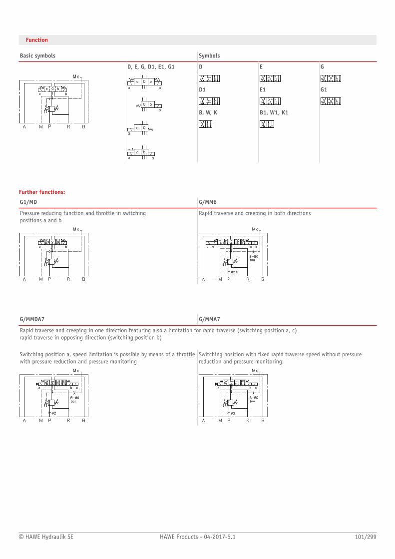
© HAWE Hydraulik SE HAWE Products - 04-2017-5.1 101/299
Function
Basic symbols Symbols
D, E, G, D1, E1, G1 D E G
D1 E1 G1
B, W, K B1, W1, K1
Further functions:
G1/MD G/MM6
Pressure reducing function and throttle in switching positions a and b
Rapid traverse and creeping in both directions
G/MMDA7 G/MMA7
Rapid traverse and creeping in one direction featuring also a limitation for rapid traverse (switching position a, c)rapid traverse in opposing direction (switching position b) Switching position a, speed limitation is possible by means of a throttlewith pressure reduction and pressure monitoring
Switching position with xed rapid traverse speed without pressurereduction and pressure monitoring.

102/299 HAWE Products - 04-2017-5.1 © HAWE Hydraulik SE
General parameters and dimensions
NSMD2 K... NSMD2 G...
Qmax
[lpm]pmax
[bar]Clampingpressurerange [bar]
Trigger ow[lpm]
Connection hole pattern1)
Dimensions[mm]
m[kg]
H B T Individualvalve2)
Additionalfunction
NSMD2 25 120 H: 2 ... 17A: 4 ... 36G: 5 ... 50B: 6 ... 60E: 8 ... 80
1: 1 ... 3-: 2 ... 43: 3 ... 54: 4 .. .65: 5 ... 76: 6 ....87: 7 ... 9
Hole patternconf. DIN 24340-A6
see illustration 2.2 ... 3.8 + 0.6 ... 1.1
1) Mx port: G 1/82) Depending on circuit symbol and actuation type

© HAWE Hydraulik SE HAWE Products - 04-2017-5.1 103/299
Associated technical data sheets:■ Clamping module type NSMD: D 7787
Products:■ Directional valves type NSWP2: Page 72■ Directional seated valves type NBVP16: Page 134
Plates:■ Valve banks type BA2: Page 144■ Intermediate plate type NZP: D 7788 Z
Male connectors:■ Line connector type MSD and others: D 7163■ With economy circuit: D 7813, D 7833
Circuit examples:
NSMD2K/M/GDK/B2.5-G24
Clamping module type NSMD size 2 with standard connection diagram in accordance with DIN 24340-A6, circuit symbol K, detented version,
clamping pressure range G, 5-50 bar and min. switching ow rate 2-4 lpm. Clamping pressure adjustment with a tracked pressure switch is
actuated using a wing bolt and wing nut.
A 2.5 mm # orice is present in the P gallery, 24V DC solenoid voltage.
NSMD2G1/MD/E4VK/B1-G12
Clamping module type NSMD size 2 with standard connection diagram, in accordance with DIN 24340-A6, circuit symbol G1 with pressure monitor-
ing at port A, adjustable throttle position for switching position a and b. Valve for clamping pressure range E, 8-80 bar and switching ow rate 4-6
lpm. Clamping pressure adjustment with a tracked pressure switch is actuated using a self-locking turn knob. A 1 mm # orice is present in the P
gallery, 12V DC solenoid voltage.
Circuit example:
HK 43L/1M-Z 9,8-AL 21F2-F60/70-2-BA 2 - NSMD2K/M/GDK/B2,5/0 - NSMD2D/MMDA7/GDK/B2/0-G24
1 End position control
2 Clamping device
3 Releasable double check valve
4 Stand-still controller
5 Tailstock spindle
6 Releasable check valve
7 End plate
coding 11
8 Clamping module with sub-plate
9 Compact hydraulic power pack with
connection block

Valves
104/299 HAWE Products - 04-2017-5.1 © HAWE Hydraulik SE
2.2 Directional seated valves
Directional seated valve type G, WG and others 108
Valve bank (directional seated valve) type VB 114
Directional seated valve type WN and WH 118
Valve bank (directional seated valve) type BWN and BWH 120
Valve bank (directional seated valve) type BVH 124
Directional seated valve type VZP 128
Directional seated valve type EM and EMP 130
Directional seated valve type BVG, BVP and NBVP 134
Directional seated valve type BVE 138
Directional seated valve type VP 140
Directional seated valve type VH, VHR, and VHP 142
Valve bank (nominal size 6) type BA 144
Lifting/lowering valve type HSV 150
Switch unit type CR 152
Lifting module type HMT and HST 154
Directional seated valve bank type VB
Valve banktype BVH
Directional seated valves type BVG, BVE, BVP and NBVP

© HAWE Hydraulik SE HAWE Products - 04-2017-5.1 105/299
(Solenoid-actuated) seated valves
Type Design / actuation p max
(bar)Q max
(lpm)
G, WG and Others Directional seated valve with various actuations■ Individual valve for manifold mounting
– Solenoid– Pressure-actuated– Manual
0: 5001: 7002: 7003: 4004: 350
0: 61: 122: 253: 654: 120
VB Directional seated valve, zero-leakage, valve bank■ For pipe connection■ Combination with pump units
– Solenoid– Pressure-actuated– Manual
01: 50011: 70021: 70031: 40041: 350
01: 611: 1221: 2531: 6041: 120
WN, WH Directional seated valve, zero-leakage, single valve■ Individual valve for manifold mounting■ Combination with connection block for pipe
connection
– Solenoid
WN - 1: 350
WH - 1: 450WH - 2: 350WH - 3: 350WH - 4: 350
WN - 1: 5
WH - 1: 8WH - 2: 15WH - 3: 30WH - 4: 60
BWH, BWN Directional seated valve, zero-leakage, valve bank■ For pipe connection■ Combination with pump units
– Solenoid
BWN - 1: 350
BWH - 1: 450BWH - 2: 350BWH - 3: 350
BWN - 1: 5
BWH - 1: 8BWH - 2: 15BWH - 3: 30
BVH Version■ Valve bank for pipe connection
– Solenoid
11: 400 11: 20
VZP Directional seated valve, zero-leakage, single valve■ Individual valve for manifold mounting
– Solenoid
1: 450 1: 15
EM, EMP Directional seated valve, zero-leakage, single valve■ Screw-in valve■ Combination with connection block for pipe
connection■ Combination with connection block for swivel tting
– Solenoid
EM - 1: 450EM - 2: 400EM - 3: 400EM - 4: 350
EMP - 2: 400EMP - 3: 400EMP - 4: 350
EM - 1: 20EM - 2: 40EM - 3: 80EM - 4: 160
EMP - 2: 40EMP - 3: 80EMP - 4: 160
BVG, BVP, NBVP Directional seated valve, zero-leakage, single valve■ For pipe connection■ Individual valve for manifold mounting
– Solenoid– Hydraulic– Pneumatic– Manual
1: 400 1: 20
BVE Directional seated valve, zero-leakage, single valve■ Screw-in valve■ Combination with connection block for pipe
connection■ Combination with connection block for manifold
mounting
– Solenoid
1: 5003: 4005: 400
1: 203: 705: 300
VP Directional seated valve, zero-leakage, single valve■ Individual valve for manifold mounting
1: 400 1: 15

106/299 HAWE Products - 04-2017-5.1 © HAWE Hydraulik SE
Type Design / actuation p max
(bar)Q max
(lpm)
– Solenoid– Hydraulic– Pneumatic
VH, VHR, VHP Directional seated valve, zero-leakage■ Single valve for pipe connection■ Individual valve for manifold mounting■ Valve bank
– Manual
VH - 1: 700VH - 2: 500
VHP - 1: 700
VHR - 1: 700VHR - 2: 500
VH - 1: 12VH - 2: 25
VHP - 1: 12
VHR - 1: 12VHR - 2: 25

© HAWE Hydraulik SE HAWE Products - 04-2017-5.1 107/299
Valve combinations
Type Design / actuation p max
(bar)Q max
(lpm)
BA Valve bank■ Directional spool valve■ Directional spool valve■ Directional seated valve
– Solenoid– Pressure-actuated– Manual– Mechanical
2: 500 2: 50
HSV ■ Single valve for pipe connection
– Solenoid
21: 31522: 31561: 35071: 400
21: 2022: 3061: 6071: 120
CR ■ Single valve for pipe connection
– Solenoid– Manual
HP/LP:4: 400/605: 400/60
HP/LP:4: 8/805: 20/160
HMT, HST ■ Valve bank
– Solenoid
HST - 2: 315HST - 3: 315
HMT - 3: 315
HST - 2: 40HST - 3: 80
HMT - 3: 90
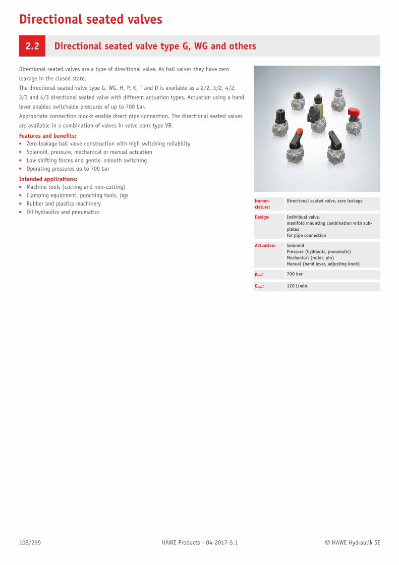
Directional seated valves
108/299 HAWE Products - 04-2017-5.1 © HAWE Hydraulik SE
2.2 Directional seated valve type G, WG and others
Directional seated valves are a type of directional valve. As ball valves they have zero
leakage in the closed state.
The directional seated valve type G, WG, H, P, K, T and D is available as a 2/2, 3/2, 4/2,
3/3 and 4/3 directional seated valve with different actuation types. Actuation using a hand
lever enables switchable pressures of up to 700 bar.
Appropriate connection blocks enable direct pipe connection. The directional seated valves
are available in a combination of valves in valve bank type VB.
Features and benets:■ Zero-leakage ball valve construction with high switching reliability■ Solenoid, pressure, mechanical or manual actuation■ Low shifting forces and gentle, smooth switching■ Operating pressures up to 700 bar
Intended applications:■ Machine tools (cutting and non-cutting)■ Clamping equipment, punching tools, jigs■ Rubber and plastics machinery■ Oil hydraulics and pneumatics
Nomen-clature:
Directional seated valve, zero leakage
Design: Individual valve, manifold mounting combination with sub-plates for pipe connection
Actuation: Solenoid Pressure (hydraulic, pneumatic)Mechanical (roller, pin)Manual (hand lever, adjusting knob)
pmax: 700 bar
Qmax: 120 l/min

© HAWE Hydraulik SE HAWE Products - 04-2017-5.1 109/299
Design and order coding example
G R2 - 3 R - 1/2 - G24
Solenoid voltage 12V DC, 24V DC, 110V AC, 230V AC
Indiv. connection blocks for pipe connection Additional versions:■ Connection blocks with by-pass check valve or pressure limiting valve
between P and R■ Connection block with bridge rectifier circuit. Check valves in
"GRAETZ"-circuitry ensure ow direction through the valve
Additional elements ■ With check valve insert for port P■ With check valve insert for port P■ With return pressure stop for port R■ Position monitoring (size 3 and 4)
Size Size 0 to 4
■ Size 1 also available with industrial connection hole pattern NG 6 (CETOP), type NG■ Size 12 with interchangeable coil■ Size 22 reinforced version 700 bar
Function ■ 2/2-way directional valve (R2, S2)■ 3/2-way directional valve (3, Z3)■ 3/3-way directional valve (21, 39)■ 4/3 directional valve (22, 45, 46, 47, 48, 49)■ 4/2-way directional valve (4, Z4)
Actuation ■ Solenoid (G, WG)■ Hydraulic (H)■ Pneumatic (P)■ Mechanical (K, T, F, D)
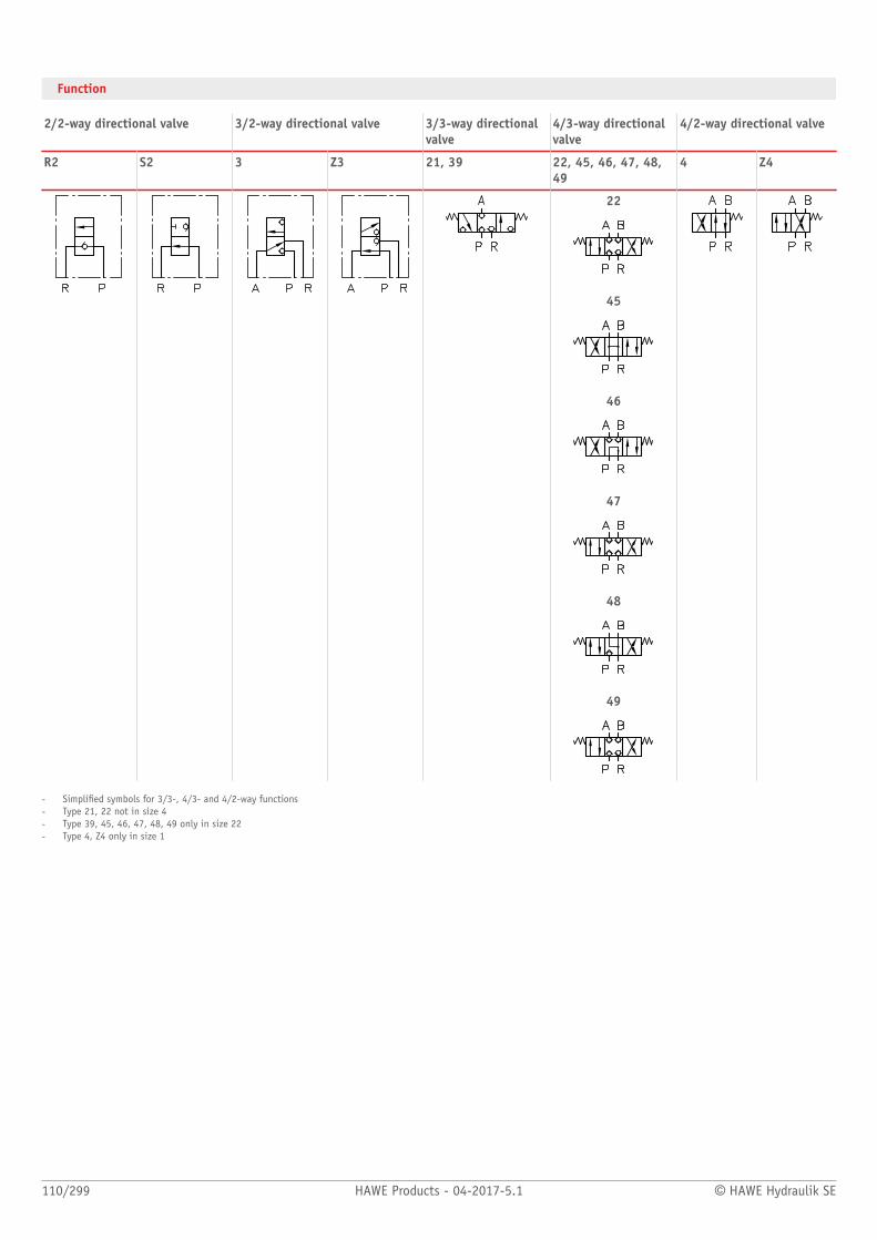
110/299 HAWE Products - 04-2017-5.1 © HAWE Hydraulik SE
Function
2/2-way directional valve 3/2-way directional valve 3/3-way directionalvalve
4/3-way directionalvalve
4/2-way directional valve
R2 S2 3 Z3 21, 39 22, 45, 46, 47, 48,49
4 Z4
22
45
46
47
48
49
- Simplied symbols for 3/3-, 4/3- and 4/2-way functions- Type 21, 22 not in size 4- Type 39, 45, 46, 47, 48, 49 only in size 22- Type 4, Z4 only in size 1
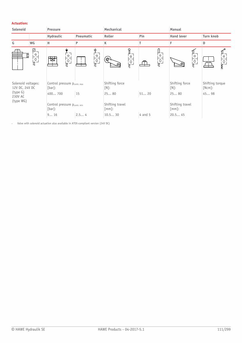
© HAWE Hydraulik SE HAWE Products - 04-2017-5.1 111/299
Actuation:
Solenoid Pressure Mechanical Manual
Hydraulic Pneumatic Roller Pin Hand lever Turn knob
G WG H P K T F D
Control pressure pcontr. max
[bar]:Shifting force [N]:
Shifting force [N]:
Shifting torque [Ncm]:
400... 700 15 25... 80 51... 20 25... 80 45... 98
Control pressure pcontr. min
[bar]:
Shifting travel [mm]:
Shifting travel [mm]:
Solenoid voltages:12V DC, 24V DC (type G) 230V AC (type WG)
9... 16 2.5... 4 10.5... 30 4 and 5 20.5... 45
- Valve with solenoid actuation also available in ATEX-compliant version (24V DC)
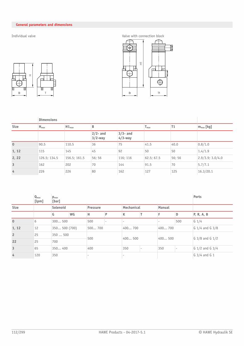
112/299 HAWE Products - 04-2017-5.1 © HAWE Hydraulik SE
General parameters and dimensions
Individual valve Valve with connection block
Dimensions
Size Hmax H1max B Tmax T1 mmax [kg]
2/2- and 3/2-way
3/3- and 4/3-way
0 90.5 110.5 36 75 41.5 40.0 0.8/1.0
1, 12 115 145 45 92 50 50 1.4/1.9
2, 22 126.5; 134.5 156.5; 161.5 56; 56 116; 116 62.5; 67.5 56; 56 2.9/3.9; 3.0/4.0
3 162 202 70 144 91.5 70 5.7/7.1
4 226 226 80 162 127 125 16.3/20.1
Qmax
[lpm]pmax
[bar]Ports
Size Solenoid Pressure Mechanical Manual
G WG H P K T F D P, R, A, B
0 6 300... 500 500 - - - 500 G 1/4
1, 12 12 350... 500 (700) 500... 700 400... 700 400... 700 G 1/4 and G 3/8
2 25 350 ... 500
22 25 700500 400... 500 400... 500 G 3/8 and G 1/2
3 65 350... 400 400 350 - 350 - G 1/2 and G 3/4
4 120 350 - - G 3/4 and G 1

© HAWE Hydraulik SE HAWE Products - 04-2017-5.1 113/299
Associated technical data sheets:■ Directional seated valve type G, WG and others: D 7300■ Directional seated valve type NG, NGW and others: D 7300 N■ Directional seated valve type G, WG and others with position
monitoring: D 7300 H
Valve banks:■ Valve banks type VB: Page 114
Male connectors:■ Line connector type MSD and others: D 7163■ With economy circuit: D 7813, D 7833
Circuit example:
RZ 4.0/2-12.3-B 75-V 5.5
- 3 x 690/400 V 50 Hz
VB 22 AM 1/500
-G 49/U 22
-8 E-2-G 24
GR 2-12-3/8 C-G 24

Directional seated valves
114/299 HAWE Products - 04-2017-5.1 © HAWE Hydraulik SE
2.2 Valve bank (directional seated valve) type VB
A valve bank combines different valves for operating independent consumers.
The valve bank type VB comprises several directional seated valves of type G, WG among
others that are connected in parallel. The directional seated valves as ball valves have zero
leakage in the closed state. They are attached to sub-plates. These sub-plates are clamped
between the inlet section (P and R port) and the end plate via tension rods. Pressure
switches or pressure-limiting valves can be integrated into the pumps and/or consumer
lines.
2/2 and 3/2- 4/2, 3/3 and 4/3 directional seated valves are available with different types
of actuation. The valve bank can be mounted directly to compact hydraulic power packs
using connection blocks.
Features and benets:■ Compact hydraulic controls for high pressure■ Combination with compact hydraulic power packs result in cost efcient
turn-key solutions■ Elimination of time-consuming installation due to combination with hydraulic power
packs■ Simple repairs thanks to modular structure of the systems
Intended applications:■ Machine tools (chipping and non-chipping)■ Clamping, punching and jigs■ Rubber and plastics machinery■ Oil hydraulics and pneumatics
Nomen-clature:
Directional seated valve, zero leakage
Design: Valve bank for pipe connection
Actuation: Solenoid Pressure: Hydraulic, PneumaticManual: Hand lever, Turn knob
pmax: 700 bar
Qmax: 120 l/min
Design and order coding example
VB12 F M DCNR5 1 WG230
Solenoid voltage 12V DC, 24V DC, 110V AC, 230V AC
Port size G 1/4 (1), G 3/8 (2), G 1/2 (3) (BSPP)
Valve sections Symbols: 2/2-way directional valve, 3/2-way directional valve, 3/3-way directional valve, 4/3-way directional valve, 4/2-way directional valve
Valve section options■ Pressure switch for P or the consumer side■ Pressure reducing valve reducing the pressure in the downstream gallery P■ Orices in gallery P and/or return pressure stop in gallery R
Sub-plates■ With 2-way ow controller by-passing to the tank■ Pressure reducing valve reducing the pressure in the downstream gallery P■ With pressure limiting valve and throttle■ With idle circulation valve and/or shuttle valve
Intermediate plates■ With pressure reduction for gallery P or throttle for port A (parallel connection)
Actuation
Connection block/adapter plate ■ For pipe connection■ For direct mounting at compact hydraulic power packs■ For direct mounting at hydraulic power packs
Basic type, size Type VB size 01, 12, 21, 22, 31, 41
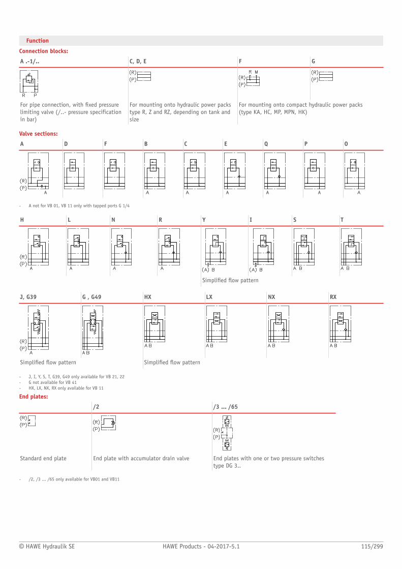
© HAWE Hydraulik SE HAWE Products - 04-2017-5.1 115/299
Function
Connection blocks:
A .-1/.. C, D, E F G
For pipe connection, with xed pressurelimiting valve (/..- pressure specificationin bar)
For mounting onto hydraulic power packstype R, Z and RZ, depending on tank andsize
For mounting onto compact hydraulic power packs (type KA, HC, MP, MPN, HK)
Valve sections:
A D F B C E Q P O
- A not for VB 01, VB 11 only with tapped ports G 1/4
H L N R Y I S T
Simplied ow pattern
J, G39 G , G49 HX LX NX RX
Simplied ow pattern Simplied ow pattern
- J, I, Y, S, T, G39, G49 only available for VB 21, 22- G not available for VB 41- HX, LX, NX, RX only available for VB 11
End plates:
/2 /3 ... /65
Standard end plate End plate with accumulator drain valve End plates with one or two pressure switchestype DG 3..
- /2, /3 ... /65 only available for VB01 and VB11
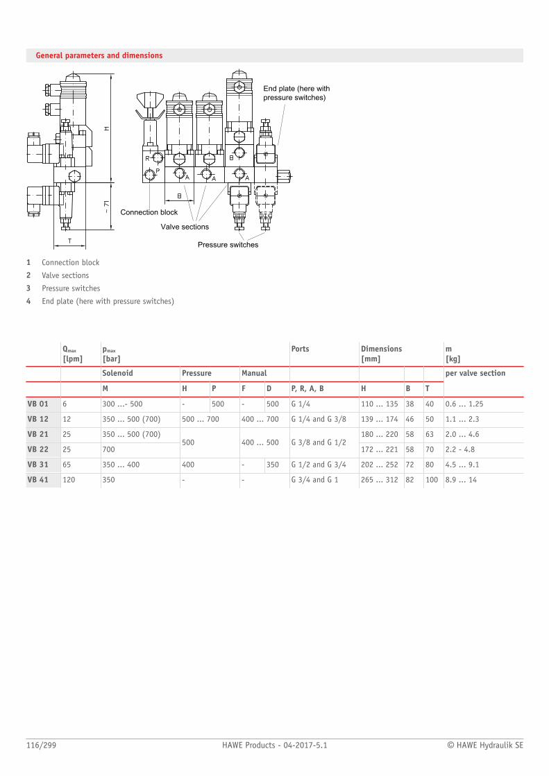
116/299 HAWE Products - 04-2017-5.1 © HAWE Hydraulik SE
General parameters and dimensions
Connection block
Valve sections
Pressure switches
End plate (here withpressure switches)
1 Connection block
2 Valve sections
3 Pressure switches
4 End plate (here with pressure switches)
Qmax
[lpm]pmax
[bar]Ports Dimensions
[mm]m[kg]
Solenoid Pressure Manual
M H P F D P, R, A, B H B T
per valve section
VB 01 6 300 ...- 500 - 500 - 500 G 1/4 110 ... 135 38 40 0.6 ... 1.25
VB 12 12 350 ... 500 (700) 500 ... 700 400 ... 700 G 1/4 and G 3/8 139 ... 174 46 50 1.1 ... 2.3
VB 21 25 350 ... 500 (700) 180 ... 220 58 63 2.0 ... 4.6
VB 22 25 700500 400 ... 500 G 3/8 and G 1/2
172 ... 221 58 70 2.2 - 4.8
VB 31 65 350 ... 400 400 - 350 G 1/2 and G 3/4 202 ... 252 72 80 4.5 ... 9.1
VB 41 120 350 - - G 3/4 and G 1 265 ... 312 82 100 8.9 ... 14
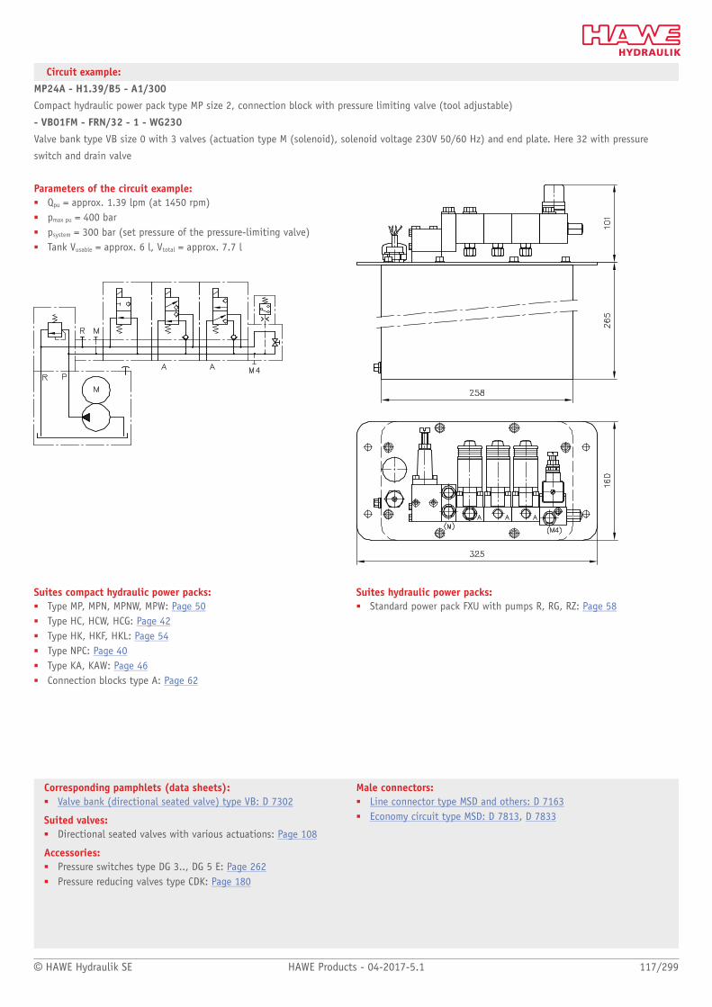
© HAWE Hydraulik SE HAWE Products - 04-2017-5.1 117/299
Corresponding pamphlets (data sheets):■ Valve bank (directional seated valve) type VB: D 7302
Suited valves:■ Directional seated valves with various actuations: Page 108
Accessories:■ Pressure switches type DG 3.., DG 5 E: Page 262■ Pressure reducing valves type CDK: Page 180
Male connectors:■ Line connector type MSD and others: D 7163■ Economy circuit type MSD: D 7813, D 7833
Circuit example:
MP24A - H1.39/B5 - A1/300
Compact hydraulic power pack type MP size 2, connection block with pressure limiting valve (tool adjustable)
- VB01FM - FRN/32 - 1 - WG230
Valve bank type VB size 0 with 3 valves (actuation type M (solenoid), solenoid voltage 230V 50/60 Hz) and end plate. Here 32 with pressure
switch and drain valve
Parameters of the circuit example:■ Qpu = approx. 1.39 lpm (at 1450 rpm)■ pmax pu = 400 bar■ psystem = 300 bar (set pressure of the pressure-limiting valve)■ Tank Vusable = approx. 6 l, Vtotal = approx. 7.7 l
Suites compact hydraulic power packs:■ Type MP, MPN, MPNW, MPW: Page 50■ Type HC, HCW, HCG: Page 42■ Type HK, HKF, HKL: Page 54■ Type NPC: Page 40■ Type KA, KAW: Page 46■ Connection blocks type A: Page 62
Suites hydraulic power packs:■ Standard power pack FXU with pumps R, RG, RZ: Page 58

Directional seated valves
118/299 HAWE Products - 04-2017-5.1 © HAWE Hydraulik SE
2.2 Directional seated valve type WN and WH
Directional seated valves are a type of directional valve. As ball valves they have zero
leakage in the closed state.
The directional seated valves type WN and WH are manifold mounting valves. 2/2 and 3/2
directional seated valves are available. These are also available combined as 3/3 and 4/3
directional seated valves. The type WH contains an internal pressure balance. As a result,
the permissible operating pressure is higher than the type WN.
Appropriate connection blocks enable direct pipe connection. The directional seated valves
are available in a combination of valves in valve bank type BWN and BWH.
Features and benets:■ Excellent price/performance ratio■ Compact design■ Directional seated valves with zero leakage■ Solenoid version with 8-watt technology
Intended applications:■ Machines for forestry and agricultural purposes■ Clamping, punching and jigs■ Clamping equipment, punching tools, jigs■ Process engineering systems
Nomen-clature:
Directional seated valve, zero leakage
Design: Individual valve, manifold mountingcombination with connection blocks for pipeconnection
Actuation: Solenoid
pmax: 450 bar
Qmax: 60 l/min
Design and order coding example
WN1 H 1 - 1/4 - G24
Solenoid voltage 12V DC, 24V DC, 110V AC, 230V AC
■ Versions with M12-plug and 8-Watt solenoid
Single connection block Port size G 1/4, G 3/8, G 1/2 (BSPP)
■ By-pass check valve or pressure limiting valve between P and R
Additional elements ■ Return pressure stop for port R■ Check valve insert for port P■ Pressure limiting valve
Function ■ 2/2-way directional valve (F, D, Q, E)■ 3/2-way directional valve (H, R, M, N)■ 3/3-way directional valve (J, U)■ 4/2-way directional valve (W)
Basic type, size Type WN, size 1Type WH, size 1 to 4
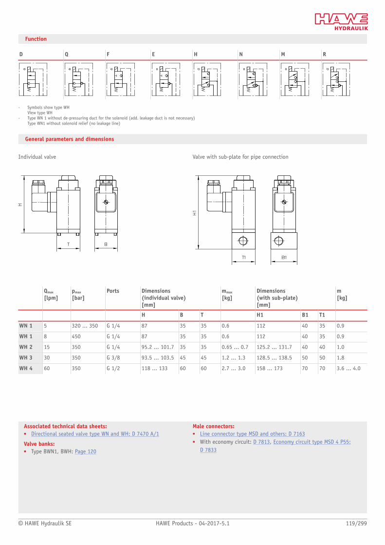
© HAWE Hydraulik SE HAWE Products - 04-2017-5.1 119/299
Associated technical data sheets:■ Directional seated valve type WN and WH: D 7470 A/1
Valve banks:■ Type BWN1, BWH: Page 120
Male connectors:■ Line connector type MSD and others: D 7163■ With economy circuit: D 7813, Economy circuit type MSD 4 P55:
D 7833
Function
D Q F E H N M R
- Symbols show type WHView type WH
- Type WN 1 without de-pressuring duct for the solenoid (add. leakage duct is not necessary)Type WN1 without solenoid relief (no leakage line)
General parameters and dimensions
Individual valve Valve with sub-plate for pipe connection
Qmax
[lpm]pmax
[bar]Ports Dimensions
(individual valve) [mm]
mmax
[kg]Dimensions(with sub-plate) [mm]
m[kg]
H B T H1 B1 T1
WN 1 5 320 ... 350 G 1/4 87 35 35 0.6 112 40 35 0.9
WH 1 8 450 G 1/4 87 35 35 0.6 112 40 35 0.9
WH 2 15 350 G 1/4 95.2 ... 101.7 35 35 0.65 ... 0.7 125.2 ... 131.7 40 40 1.0
WH 3 30 350 G 3/8 93.5 ... 103.5 45 45 1.2 ... 1.3 128.5 ... 138.5 50 50 1.8
WH 4 60 350 G 1/2 118 ... 133 60 60 2.7 ... 3.0 158 ... 173 70 70 3.6 ... 4.0

Directional seated valves
120/299 HAWE Products - 04-2017-5.1 © HAWE Hydraulik SE
2.2 Valve bank (directional seated valve) type BWN and BWH
A valve bank combines different valves for operating independent consumers.
The valve bank type BWN or BWH comprises several directional seated valves of type WN
or WH that are connected in parallel. The directional seated valves as ball valves have zero
leakage in the closed state. They are attached to sub-plates. These sub-plates are clamped
between the inlet section (P and R port) and the end plate via tension rods. Pressure
switches or pressure-limiting valves can be integrated into the pumps and/or consumer
lines.
2/2 and 3/2- directional seated valves . Combined, these are also available as 3/3 and 4/3
directional seated valves. The valve bank can be mounted directly to compact hydraulic
power packs using connection blocks.
Features and benets:■ Modular concept■ Adapter plates for ange-mounting on hydraulic power packs or combination with other
valve types■ With the valve bank version, option to incorporate additional functions in the sub-plate,
such as pressure-limiting valves, pressure switches etc.■ Energy-efcient solutions in connection with hydraulic accumulators
Intended applications:■ Machine tools (chipping and non-chipping)■ Rubber and plastic machinery■ Mining machinery (incl. oil production)■ Rubber and plastics machinery
Nomen-clature:
Directional seated valve, zero leakage
Design: Valve bank
■ For pipe connection■ Combination with hydraulic power packs
Actuation: Solenoid
pmax: 450 bar
Qmax: 30 lpm

© HAWE Hydraulik SE HAWE Products - 04-2017-5.1 121/299
Design and order coding example
BWH2 A-1/300 - FH5N5 - 1 - 1 - G24
Solenoid voltage 12V DC, 24V DC, 110V AC, 230V AC
■ Versions with M12-plug and 8-Watt solenoid
Port size G 1/4, G 3/8 (BSPP)
End plate ■ With one or two pressure switches■ With accumulator drain valve■ With additional pressure limiting valve in gallery P
Valve sections ■ Directional valves type WH or WN■ Valve section options:
■ Return pressure stop■ Pressure switch for the consumer ports or for gallery P■ Pressure limiting valves at the consumer port■ Pressure reducing valve reducing the pressure in the downstream P gallery
■ Additional sections:
■ Pressure reducing valve■ Indiv. sub-plate with pressure switch■ Separation plate for gallery P
Connection block/adapter plates ■ For pipe connection, with/without pressure limiting valve, manually or xed, with/withoutprop. pressure limiting valve
■ For direct mounting at compact hydraulic power packs■ For direct mounting at hydraulic power packs■ Adapter plates for combination with directional valves type BVZP or SWR/SWP
Basic type, size Type BWN, size 1 and type BWH, size 1 to 3
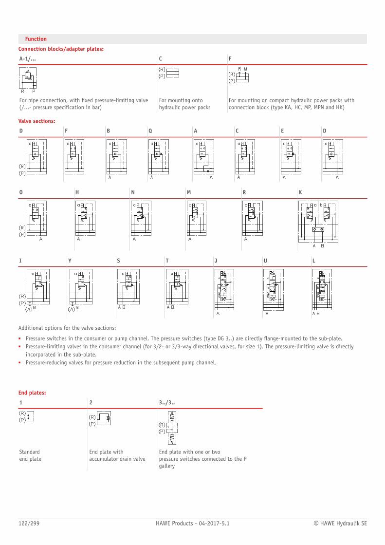
122/299 HAWE Products - 04-2017-5.1 © HAWE Hydraulik SE
Function
Connection blocks/adapter plates:
A-1/... C F
For pipe connection, with xed pressure-limiting valve(/...- pressure specification in bar)
For mounting ontohydraulic power packs
For mounting on compact hydraulic power packs withconnection block (type KA, HC, MP, MPN and HK)
Valve sections:
D F B Q A C E D
O H N M R K
I Y S T J U L
Additional options for the valve sections:
■ Pressure switches in the consumer or pump channel. The pressure switches (type DG 3..) are directly ange-mounted to the sub-plate.■ Pressure-limiting valves in the consumer channel (for 3/2- or 3/3-way directional valves, for size 1). The pressure-limiting valve is directly
incorporated in the sub-plate.■ Pressure-reducing valves for pressure reduction in the subsequent pump channel.
End plates:
1 2 3../3..
Standard end plate
End plate with accumulator drain valve
End plate with one or two pressure switches connected to the Pgallery

© HAWE Hydraulik SE HAWE Products - 04-2017-5.1 123/299
Associated publications:■ Valve bank (directional seated valve) type BWN and BWH:
D 7470 B/1■ Directional seated valve type WN and WH: D 7470 A/1
Connection block:■ Type A: Page 62
Compact hydraulic power packs:■ Type HC, HCW, HCG: Page 42■ Type HK, HKF, HKL: Page 54
■ Type NPC: Page 40■ Type KA, KAW: Page 46
Hydraulic accessories:■ Pressure switches type DG 3.., DG 5E: Page 262■ Pressure reducing valves type CDK: Page 180
General parameters and dimensions
Version for pipe connection:
Connection block
End plate
Pressure switch
Valve sections
1 Connection block
2 Valve sections
3 End plate
4 Pressure switches
Qmax
[lpm]pmax
[bar]PortsP, R, A, B
Dimensions [mm] m [kg]
H T B
BWN 1 5 350 G 1/4 116.5 ... 131.5 38 40 0.8 ... 0.9
BWH 1 8 450 G 1/4 116.5 ... 131.5 38 40 0.8 ... 0.9
BWH 2 15 350 G 1/4 122 ... 157.5 38 50 0.9 ... 1.1
BWH 3 30 350 G 3/8 155.5 ... 168 50 60 1.9 ... 2.4
- Weight m [kg] per individual element: + 0.3 kg per pressure switch tted
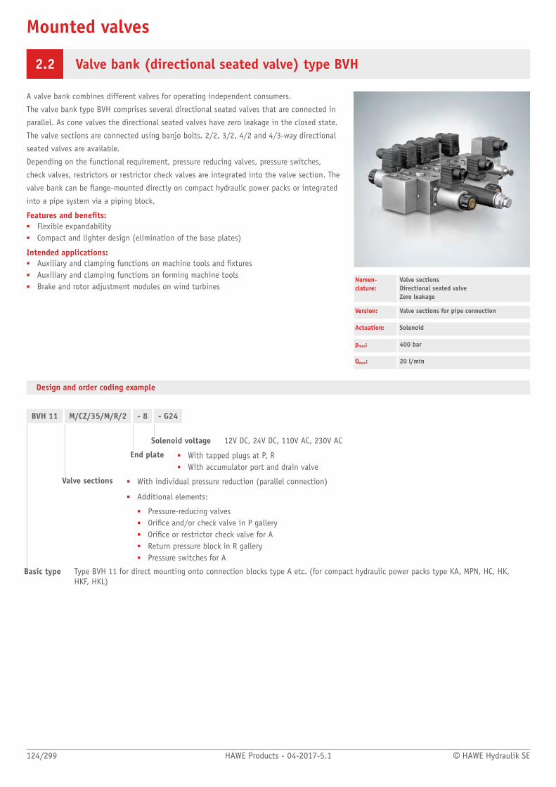
Mounted valves
124/299 HAWE Products - 04-2017-5.1 © HAWE Hydraulik SE
2.2 Valve bank (directional seated valve) type BVH
A valve bank combines different valves for operating independent consumers.
The valve bank type BVH comprises several directional seated valves that are connected in
parallel. As cone valves the directional seated valves have zero leakage in the closed state.
The valve sections are connected using banjo bolts. 2/2, 3/2, 4/2 and 4/3-way directional
seated valves are available.
Depending on the functional requirement, pressure reducing valves, pressure switches,
check valves, restrictors or restrictor check valves are integrated into the valve section. The
valve bank can be ange-mounted directly on compact hydraulic power packs or integrated
into a pipe system via a piping block.
Features and benets:■ Flexible expandability■ Compact and lighter design (elimination of the base plates)
Intended applications:■ Auxiliary and clamping functions on machine tools and xtures■ Auxiliary and clamping functions on forming machine tools■ Brake and rotor adjustment modules on wind turbines
Nomen-clature:
Valve sectionsDirectional seated valveZero leakage
Version: Valve sections for pipe connection
Actuation: Solenoid
pmax: 400 bar
Qmax: 20 l/min
Design and order coding example
BVH 11 M/CZ/35/M/R/2 - 8 - G24
Solenoid voltage 12V DC, 24V DC, 110V AC, 230V AC
End plate ■ With tapped plugs at P, R■ With accumulator port and drain valve
Valve sections ■ With individual pressure reduction (parallel connection)
■ Additional elements:
■ Pressure-reducing valves■ Orice and/or check valve in P gallery■ Orice or restrictor check valve for A■ Return pressure block in R gallery■ Pressure switches for A
Basic type Type BVH 11 for direct mounting onto connection blocks type A etc. (for compact hydraulic power packs type KA, MPN, HC, HK,HKF, HKL)

© HAWE Hydraulik SE HAWE Products - 04-2017-5.1 125/299
Function
Connection blocks/adapter plates:
BVH
Direct mounting onto connection blocks type A etc. for compact hydraulic power packs type KA, MPN, HC, HK, HKF, HKL
Valve sections:
H M W D G
Additional options for the valve sections:
Individual pressure reduction (parallel connection) Pressure lter
BVH 11 H/CZ... BVH 11 W/CZ... BVH 11 G/CZ... BVH 11 ZD
Actuations:
M: Solenoid actuation (pmax= 400 bar)
GM: Solenoid actuation (pmax= 250 bar)
End plates:
-1 -81
Tapped plug at P, R with accumulator port and drain valve

126/299 HAWE Products - 04-2017-5.1 © HAWE Hydraulik SE
General parameters and dimensions
(A1F1/310) - BVH 11 H/M/R/2- BVH 11 M/M/R B2.5/3- BVH 11 W/CZ 5/35/M/R/22 - 81 - G 24Valve section 1 with 3/2-way function circuit symbol H, P check valve (coding R), no pressure switch (coding 2)Valve section 2 with 3/2-way function circuit symbol M, check valve and orice in P gallery (coding R, B, 2, 5) andpressure switch for A (coding 3)Valve section 3 with 4/2-way function circuit symbol W, individual pressure-reducing valve set to 35 bar (codingCZ5/35) and check valve in P gallery (coding R), no pressure switch
Type BVH valve bank fordirect mounting at type Aconnection block
End plate for accumulator port (coding 8) and 24V DC solenoid voltage
Mounted valve type BVH
Qmax
[lpm]pmax
[bar]Ports(BSPP)
Dimensions [mm]
m[kg]
A, B, P, R, M H H1 B T Valve section
BVH 20 400 G 1/4 60 343 40/50 60 0,8

© HAWE Hydraulik SE HAWE Products - 04-2017-5.1 127/299
Associated technical data sheets:■ Valve bank (directional seated valve) type
BVH: D 7788 BV
Compact hydraulic power packs:■ See section
"Compact hydraulic power packs"
Connection blocks:■ Type A: Page 62
Combinable products:■ Directional seated valves type NBVP:
Page 134■ Pressure reducing valves type CDK, DK:
Page 180
Accessories:■ Pressure switches type DG: Page 262■ Hydraulic accumulator type AC: Page 258
Plug:■ Line connector type MSD and others:
D 7163
Circuit example:
KA 281 SKT/Z 9.8 - AX 3 F 1 E/120- BVH 11 W/M/RH/2- BVH 11 M/CZ5/35/M/RHB 2.5- BVH 11 M/CZ5/35/M/RHB 2.5- 82-X 24 - AC 2001/60/3/A 3x400V 50 Hz
Compact hydraulic power pack type KA1 kW motor power; Connection block with return line lter and TÜV-approved safety valve set to 120 bar
Valve bank type BVH with three valve sections,two clamping functions with individuallyadjustable clamping pressure
Parameters of the circuit example■ QPu = 9.8 lpm (at 1450 rpm)■ pmax Pu = 170 bar■ pSystem = 120 bar■ pswitch-off feature = 50 bar■ Vuse = approx. 3 l

Directional seated valves
128/299 HAWE Products - 04-2017-5.1 © HAWE Hydraulik SE
2.2 Directional seated valve type VZP
Directional seated valves are a type of directional valve. The seated valve type VZP is a
manifold mounting valve. Zero-leakage ball-seated and cone-seated valves of the same size
are combined.
The twin layout of the 3/2 and 2/2-way directional seated valves means that all functional
elements for valve function and actuation share one housing, making them very compact.
Depending on the pairing, these valves can realise either one 4/4, 4/3 or 3/3-way
function, or two independent 3/2 and 2/2-way individual functions. Compared with
individual valves for manifold mounting of conventional layout, the advantages are lower
spatial requirements and the possibility of directly mounting pressure switches for monitor-
ing the consumer pressure. A particularly compact option is to combine several valves
connected in parallel in one valve bank (type BVZP).
Features and benets:■ Good price-performance ratio■ Max. operating pressures up to 450 bar■ Adapter plates for ange-mounting on compact hydraulic power packs■ Option to incorporate additional functions in the sub-plate, such as pressure switches,
throttle and check valve combinations etc.
Intended applications:■ Machine tools (cutting and non-cutting)■ Mining machinery (incl. oil production)■ Clamping equipment, punching tools, jigs■ Rubber and plastics machinery
Nomen-clature:
Directional seated valve, zero leakage
Design: Individual valve, manifold mounting
Actuation: Solenoid
pmax: 450 bar
Qmax: 15 lpm
Design and order coding example
VZP1 H 12B1,0 - G12
Solenoid voltage 12V DC, 24V DC, 110V AC, 230V AC
■ Versions with M12-plug and 8-Watt solenoid
Additional elements ■ Indiv. valves with check valve insert in gallery P■ Indiv. valves with return pressure stop in gallery R■ Pressure switch for the consumer ports
Function ■ 4/2-way functions via directional spool valve■ 4/3-way directional seated valve (G, D, E, O)■ 3/3-way directional seated valve (J, P)■ 2/2- and 3/2-way directional seated valve (F, D - H, M, N, R)
Basic type, size Twin valve type VZP, size 1
■ Connection blocks for pipe connection
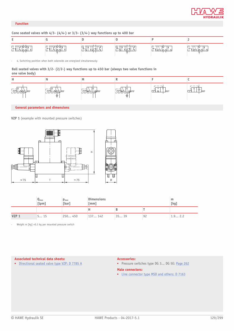
© HAWE Hydraulik SE HAWE Products - 04-2017-5.1 129/299
Associated technical data sheets:■ Directional seated valve type VZP: D 7785 A
Accessories:■ Pressure switches type DG 3.., DG 5E: Page 262
Male connectors:■ Line connector type MSD and others: D 7163
Function
Cone seated valves with 4/3- (4/4-) or 3/3- (3/4-) way functions up to 400 bar
E G D O P J
- 4. Switching position when both solenoids are energized simultaneously
Ball seated valves with 3/2- (2/2-) way functions up to 450 bar (always two valve functions in one valve body)
H N M R F C
General parameters and dimensions
VZP 1 (example with mounted pressure switches)
Qmax
[lpm]pmax
[bar]Dimensions [mm]
m [kg]
H B T
VZP 1 5... 15 250... 450 137... 142 35... 39 92 1.9... 2.2
- Weight m [kg] +0.3 kg per mounted pressure switch

Directional seated valves
130/299 HAWE Products - 04-2017-5.1 © HAWE Hydraulik SE
2.2 Directional seated valve type EM and EMP
Directional seated valves are a type of directional valve. As cone valves they are tightly
sealed without leakage in the closed state.
The directional seated valves type EM and EMP are screw-in valves. 2/2 directional
seated valves with direct or pilot-controlled electromagnetic actuation are available. The
directional seated valve type EM is available as a directional valve or damped switching
(soft-shift). Type EMP is a proportionally actuated directional seated valve with throttle
function.
Appropriate connection blocks make possible direct pipe connection or manifold mounting.
You can obtain additional components, e.g. a drain valve, bypass throttle valve, pressure
switch or ow control valve.
Features and benets:■ Zero leakage in blocked state■ Directly switching up to approx. 3 lpm and piloted up to 160 lpm■ Minimized ow resistance even at high ow rate■ Long lifetime due to hardened valve seats
Intended applications:■ Cranes and lifting equipment■ Road construction industry■ Materials handling, industrial trucks etc.■ Handling and assembly robots, etc.
Nomen-clature:
Directional seated valve, zero leakage
Design: Screw-in valve CombinationCombination with connection block for pipeconnectionCombination with connection block for swivelttingCombination with connection block formanifold mounting
Actuation: Solenoid
pmax: 450 bar
Qmax: 160 lpm
Design and order coding example
EM 21 V - 3/8 - G24
Solenoid voltage 12V DC, 24V DC, 110V AC, 230V AC
Versions with■ Versions with M12-plug and 8-Watt solenoid■ Quarter-turn plug, plugs of Co. KOSTAL or AMP
Connection blocks Versions with■ Drain valve■ Drain valve and drop-rate braking valve■ Drain valve and by-pass check valve■ Bypass- throttle■ Pressure switch■ 2-way ow controller
Function ■ V - 2/2-way valve (NC-type)■ S - 2/2-way valve (NO-type)
Basic type, size ■ Type EM: Directional valve, size 1 to 4■ Type EMP: Prop. valve, size 1 to 4

© HAWE Hydraulik SE HAWE Products - 04-2017-5.1 131/299
Function
Flow in arrowed direction Arbitrary owdirection
Flow in arrowed direction Arbitrary owdirection
Energized open Energized closed
Directly actuated
EM .1 D EM .1 DS
Pilot actuated
EM .1 V EMP .1 V EM .2 V EM .1 S EMP .1 S EM .2 S
Circuit example:
HMPL 5 US 1/PVPV/250-3
- A2 L 25/25/EI/3 BL 5 D7/120
- 32 L 25/25 C160/EI
- 32 L 63/63 C220/EI
- E4 - AMP 12 K4

132/299 HAWE Products - 04-2017-5.1 © HAWE Hydraulik SE
General parameters and dimensions
Screw-in valve Valve compl. with connection block for pipe connection
1 Screw-in valve
1 Connection block
Screw-in valve Valve with connection block
Qmax
[lpm]pmax
[bar]G m
[kg]Ports Dimensions
[mm]m[kg]
H1 H2 B T
EM 11 (D, DS) 5 450 M 14 x 1.5 0.3 G 1/4 40 approx.120
20 35 0.6
EM 21 (D, DS) 3 400 M 18 x 1.5 0.35 G 1/4 50 approx.120
30 45 0.7
G 1/4 20 35EM 1.. (V, S) 20 450 M 14 x 1.5 0.3
G 3/8
40 approx.120
25 45
0.6
G 3/8 45EM/EMP 2.. (V, S) 40 400 M 18 x 1.5 0.35
G 1/2
50 approx.120
30
50
0.7
G 1/2 55EM/EMP 3.. (V, S) 80 400 M 18 x 1.5 0.4
G 3/4
60 approx.133
40
60
1.0
G 3/4 40 65EM/EMP 4.. (V, S) 160 400 M 33 x 2 0.6
G 1
70 approx.150
50 70
1.2
- Pressure above 300 bar only with manifolds made of steel. Pay attention to the possibly reduced rigidity of the thread with other materials (e.g. cast, aluminium).

© HAWE Hydraulik SE HAWE Products - 04-2017-5.1 133/299
Associated technical data sheets:■ Directional seated valves type EM, EMP: D 7490/1, D 7490/1 E
Accessories:■ Pressure switches type DG 3.., DG 5E: Page 262■ Drop-rate braking valves type SB, SQ, SJ: Page 210■ Suitable proportional ampliers: Page 272
Male connectors:■ Line connector type MSD and others: D 7163■ With economy circuit: D 7813, D 7833■ Proportional amplifier type EV2S: Page 274
Circuit example:
KA 442 LFK/HH 13.1/13.1-SS-A 1 F 3/200-BA 2 -NBVP 16 G/R-GM/NZP 16 TSPG/TB 0/3 -NBVP 16 G/R-GM/3-2-G 24-X 84 G-9/250-3 x 400/230V 50 Hz-4.0 kW/24V DC
Suitable products:■ Intermediate plates NG 6 type NZP: D 7788 Z■ Connection blocks type HMPL and HMPV: Page 90■ Lifting/lowering valves type HSV: Page 150■ Lifting modules type HST, HMT etc.: Page 154
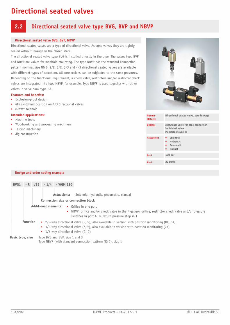
Directional seated valves
134/299 HAWE Products - 04-2017-5.1 © HAWE Hydraulik SE
2.2 Directional seated valve type BVG, BVP and NBVP
Directional seated valve BVG, BVP, NBVP
Directional seated valves are a type of directional valve. As cone valves they are tightly
sealed without leakage in the closed state.
The directional seated valve type BVG is installed directly in the pipe. The valves type BVP
and NBVP are valves for manifold mounting. The type NBVP has the standard connection
pattern nominal size NG 6. 2/2, 3/2, 3/3 and 4/3 directional seated valves are available
with different types of actuation. All connections can be subjected to the same pressures.
Depending on the functional requirement, a check valve, restrictors and/or restrictor check
valves are integrated into type NBVP, for example. Type NBVP is used together with other
valves in valve bank type BA.
Features and benets:■ Explosion-proof design■ 4th switching position on 4/3 directional valves■ 8-Watt solenoid
Intended applications:■ Machine tools■ Woodworking and processing machinery■ Testing machinery■ Jig construction
Nomen-clature:
Directional seated valve, zero leakage
Design: Individual valve for pipe connection Individual valve, Manifold mounting
Actuation: ■ Solenoid■ Hydraulic■ Pneumatic■ Manual
pmax: 400 bar
Qmax: 20 l/min
Design and order coding example
BVG1 - R /B2 - 1/4 - WGM 230
Actuations: Solenoid, hydraulic, pneumatic, manual
Connection size or connection block
Additional elements ■ Orice in one port■ NBVP: orice and/or check valve in the P gallery, orice, restrictor check valve and/or pressure
switches in port A, B, return pressure stop in T
Function ■ 2/2-way directional valve (R, S), also available in version with position monitoring (RK, SK)■ 3/2-way directional valve (Z, Y), also available in version with position monitoring (ZK)■ 4/3-way directional valve (G, D)
Basic type, size Type BVG and BVP, size 1 and 3Type NBVP (with standard connection pattern NG 6), size 1

© HAWE Hydraulik SE HAWE Products - 04-2017-5.1 135/299
Actuations:
Solenoid Hydraulic
Solenoid voltages: 12V DC, 24V DC, 110V AC, 230V AC
■ BVP 1, NBVP16 also available in ATEX-compliant version■ Version with M12 plug and 8-watt solenoid
Control pressure:pcontr. min = 24 bar pcontr max = 320 bar
Pneumatic Manual
Control pressure:pcontr. min = 2... 3.5 bar pcontr. max = 15 bar
Actuation torque:approx. 1.5 ... 3 Nm
Function
R RK S SK Z
- Further circuit symbols available
ZK Y G D
- additional switching symbols available- G, D: only for type NBVP16- Versions with contact switch for position monitoring

136/299 HAWE Products - 04-2017-5.1 © HAWE Hydraulik SE
General parameters and dimensions
BVG BVP, NBVP
Version for pipe connection (solenoid actuation)
Version for base manifold mounting (hydraulic actuation)
Qmax[lpm] pmax[bar] Ports Dimensions [mm] mmax [kg]
A, B, C Hmax Bmax Tmax
BVG 1 60 40 1.6
BVP 1
20 400/2501) G 1/4, G 3/8 115 (130)
35 39 1.0
NBVP 16 20 400/2501) NG 6 230 45 45 2.1
1) with solenoid actuation GM.. and WGM
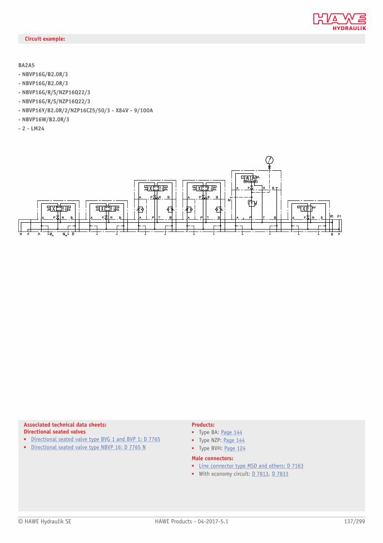
© HAWE Hydraulik SE HAWE Products - 04-2017-5.1 137/299
Associated technical data sheets: Directional seated valves■ Directional seated valve type BVG 1 and BVP 1: D 7765■ Directional seated valve type NBVP 16: D 7765 N
Products:■ Type BA: Page 144■ Type NZP: Page 144■ Type BVH: Page 124
Male connectors:■ Line connector type MSD and others: D 7163■ With economy circuit: D 7813, D 7833
Circuit example:
BA2A5
- NBVP16G/B2.0R/3
- NBVP16G/B2.0R/3
- NBVP16G/R/S/NZP16Q22/3
- NBVP16G/R/S/NZP16Q22/3
- NBVP16Y/B2.0R/2/NZP16CZ5/50/3 - X84V - 9/100A
- NBVP16W/B2.0R/3
- 2 - LM24

Directional seated valves
138/299 HAWE Products - 04-2017-5.1 © HAWE Hydraulik SE
2.2 Directional seated valve type BVE
Directional seated valves are a type of directional valve. As cone valves they are tightly
sealed without leakage in the closed state.
The directional seated valve type BVE is a screw-in valve. 2/2 and 3/2 directional seated
valves are available. All connections can be subjected to the same pressures.
Optionally a version for highly viscous media (e.g. lubricating grease) is available.
Appropriate connection blocks make possible direct pipe connection or manifold mounting.
Features and benets:■ Any ow direction■ No interaction between actuation elements and medium■ No resinification or sticking as a result of increased temperatures is possible.■ For highly viscous media (e.g. lubricating grease)
Intended applications:■ Lubrication systems■ Mining machinery■ Construction and construction material machinery■ Handling and mounting technology Nomenclature: Directional seated valve, zero leakage
Design: Individual valve for pipe connectionIndividual valve for manifold mounting
Actuation: Solenoid
pmax: 500 bar
Qmax: 300 l/min
Design and order coding example
BVE1 - R -B1,0 - G 24 - 3/8
Port size or connection block Version■ With threaded connection■ For manifold mounting
Solenoid voltages 12 V DC, 24 V DC, 110 V AC, 230 V AC
Versions with■ M12 plug and 8 watt solenoid■ AMP, DEUTSCH plugs
Additional elements ■ Orice in one port
Function ■ 2/2-way directional valve (R, S)■ 3/2-way directional valve (Z)
Basic type, size Type BVE, size 1, 3 and 5
Actuations:
Solenoid

© HAWE Hydraulik SE HAWE Products - 04-2017-5.1 139/299
Associated technical data sheets:Directional seated valves■ Directional seated valve type BVE: D 7921
Similar products■ Type BA: Page 144■ Type NZP: Page 144■ Type BVH: Page 124■ Type BVG, BVP, NBVP: Page 134
Suitable male connectors:■ Line connector type MSD and others: D 7163■ With economy circuit: D 7813, D 7833
Function
R S Z
General parameters and dimensions
Qmax [lpm] pmax [bar] Dimensions [mm] mmax [kg]
Hmax Bmax
BVE 1 20 500 121 37 0,4
BVE 3 70 400 122,5 45 0,7
BVE 5 300 400 206,5 72 1,5

Directional seated valves
140/299 HAWE Products - 04-2017-5.1 © HAWE Hydraulik SE
2.2 Directional seated valve type VP
Directional seated valves are a type of directional valve. As cone valves they are tightly
sealed without leakage in the closed state.
The directional seated valve type VP is a valve for manifold mounting. 2/2, 3/2 and 4/2
directional seated valves with different types of actuation are available. All connections
can be subjected to the same pressures.
The directional seated valve type VP is suitable above all for highly viscous media (e.g.
lubricating grease). Appropriate connection blocks make possible direct pipe connection.
Features and benets:■ Any ow direction■ No interaction between actuation elements and medium■ No sticking or resinification as a result of increased temperatures is possible.■ Suitable for highly viscous media (e.g. lubricating grease)■ Explosion-proof version
Intended applications:■ Lubricating systems■ Mining machinery■ Construction and construction materials machinery■ Handling and assembly technology
Nomen-clature:
Directional seated valve, zero leakage
Design: Manifold mounting
Actuation: Solenoid Hydraulic Pneumatic
pmax: 400 bar
Qmax: 15 l/min
Design and order coding example
VP1 - R - 3/4 - G24
Actuation ■ Solenoid■ Mechanical: roller, feeler■ Manual: lever, turn-knob
Optional connection block For direct pipe connection
Function 2/2-way directional seated valve (R, S)3/2-way directional seated valve (Z)4/2-way directional seated valve (W, G)
Basic type, size Type VP, size 1
■ Versions conforming ATEX
Actuation:
Solenoid Hydraulic Pneumatic
Solenoid voltage: 12V DC; 24V DC; 110V AC, 230V AC
Control pressure: pcontrol min = 24 bar pcontrol max = 320 bar
Control pressure: pcontrol min = 2 ... 3.5 bar pcontrol max = 15 bar

© HAWE Hydraulik SE HAWE Products - 04-2017-5.1 141/299
Associated technical data sheets:■ Directional seated valve type VP: D 7915
Similar products:■ Directional seated valve type BVG1, BVP1, NBVP16:
Page 134■ Directional seated valve type BVE:
Page 138
Male connectors:■ Line connector type MSD and others: D 7163■ With economy circuit: D 7813, D 7833
Function
R S Z G W
General parameters and dimensions
Individual valveExample: VP1R-G24
Valve with sub-plateExample: VP1W-3/4-WG 230
Qmax
[lpm]pmax
[bar]Ports Dimensions
[mm]mmax
[kg]
A, B, C Hmax Bmax Tmax
VP 1 127 40 50 1.0
VP 1 with sub-plate
15 400 G 1/4, G 3/8, G 3/4
147 ... 177 50 ... 100 45 ... 80 1.5 ... 2.2
- Hmax: Values apply for electro-magnetic actuation

Directional seated valves
142/299 HAWE Products - 04-2017-5.1 © HAWE Hydraulik SE
2.2 Directional seated valve type VH, VHR, and VHP
Directional seated valves are a type of directional valve. As ball valves they have zero
leakage in the closed state.
A hand lever operates the eccentric shaft that controls the plunger for opening or closing
the valve seats. The actuation is undertaken via the hand lever with automatic centring in
the neutral position or with a notch. The directional seated valve type VH is suitable for
pipe connection. The directional seated valve bank type VHR comprises several valves of
type VH that have been clamped together connected in parallel via a tension rod to form
a valve bank. The directional seated valve type VHP is available as a manifold mounting
valve.
Features and benets:■ Pressures up to 700 bar manually switchable■ Actuation using hand lever with automatic centring in zero position
or with notch■ Different arrangements in valve bank possible■ Leakage-free seated valve technology
Intended applications:■ Construction and construction materials machinery■ Offshore and marine technology■ Process engineering systems■ Oil hydraulics and pneumatics
Nomen-clature:
Directional seated valve, zero leakage
Design: Individual valve for pipe connection Individual valve, manifold mounting,bankable
Actuation: Manual
pmax: 700 bar
Qmax: 25 l/min
Design and order coding example
VH 1VHR 1
H1G1/N1/E2
Function/valve sections with actuation Hand lever with automatic return (1) or detent (2)
Additional versions:■ Actuation with contact switch for neutral position monitoring (K),
optionally for single valves and valve banks
Basic type, size Type VH (Individual valve for pipe connection) Type VHP (Individual valve, manifold mounting) Type VHR (Valve bank) Size 1 and 2
Actuation:
Return spring Detent
Symbol type VHR..
- Return spring : automatic return to neutral position only up to approx. 50 bar. At pressures over 50 ... 700 bar the lever must be reset manually.

© HAWE Hydraulik SE HAWE Products - 04-2017-5.1 143/299
Associated technical data sheets:■ Directional seated valve type VH, VHP and VHR: D 7647
Similar products:■ Directional seated valve type NBVP 16: D 7765 N
Function
Basic symbols Symbol
VH VHP VHR G E M N D H L S
- On type VHR max. 7 or 5 valves (size 1 or 2) can be combined- Type H, L and S only as single valve, not for type VHR
General parameters and dimensions
Individual valve VH.. Valve bank VHR..
Qmax [lpm] pmax [bar] Ports Dimensions [mm] m [kg]
H H1 B T Valve section
VH 1, VHP 1, VHR 1 12 700 G 1/4 50 172 50 90 1.6
VH 2, VHR 2 25 500 G 3/8 60 162 60 120 3

Mounted valves
144/299 HAWE Products - 04-2017-5.1 © HAWE Hydraulik SE
2.2 Valve bank (nominal size 6) type BA
A valve bank combines different valves for operating independent consumers.
The directional valve bank type BA consists of several valve sections that are tted to sub-
plates with NG 6. Using these items compact control blocks can be assembled exibly.
The intermediate plates type NZP make possible additional functions and contain, e.g.,
pressure-reducing valves, shock valves, load-holding valves etc. An intermediate plate can
be inserted between the sub-plate and the valve. The valve bank type BA can be ange-
mounted directly on the compact hydraulic power pack.
Features and benets:■ Sub-plates for exible combination of directional valve types with NG 6 (CETOP)
standard connection pattern■ Valve bank can be ange mounted directly on the connection block of a compact
hydraulic power pack or connected as a separately arranged valve bank for pipeconnection
■ Pressure switches and/or any other monitoring elements can be connected directly■ Additional elements, such as orices, throttles and check valves for connections P, R, A
and B can be integrated■ Hydraulic accumulator can be mounted directly
Intended applications:■ Clamping systems on machine tools and equipment■ Process control on deforming machine tools■ Brake and rotor adjustment modules on wind turbines
Nomenclature: Sub-plates/directional seated valve, zero leakage
Version: Valve section with sub-plates for pipeconnection
Actuation: SolenoidPressure-operated
■ Hydraulic■ Pneumatic
ManualMechanical
■ Pin■ Roller
pmax: 500 bar
Qmax: 50 lpm
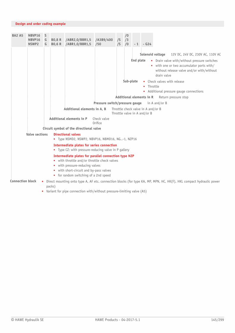
© HAWE Hydraulik SE HAWE Products - 04-2017-5.1 145/299
Design and order coding example
BA2 A5 NBVP16NBVP16NSWP2
SGG
B0,8 RB0,6 R
/ABR2,0/BBR1,5/ABR1,0/BBR1,5
/A3B9/400/50
/S/S
/0/3/0 - 1 - G24
Solenoid voltage 12V DC, 24V DC, 230V AC, 110V AC
End plate ■ Drain valve with/without pressure switches■ with one or two accumulator ports with/
without release valve and/or with/withoutdrain valve
Sub-plate ■ Check valves with release■ Throttle■ Additional pressure gauge connections
Additional elements in R Return pressure stop
Pressure switch/pressure gauge in A and/or B
Additional elements in A, B Throttle check valve in A and/or BThrottle valve in A and/or B
Additional elements in P Check valveOrice
Circuit symbol of the directional valve
Valve sections Directional valves■ Type NSMD2, NSWP2, NBVP16, NBMD16, NG..-1, NZP16
Intermediate plates for series connection■ Type CZ: with pressure-reducing valve in P gallery
Intermediate plates for parallel connection type NZP■ with throttle and/or throttle check valves■ with pressure-reducing valves■ with short-circuit and by-pass valves■ for random switching of a 2nd speed
Connection block ■ Direct mounting onto type A, AF etc. connection blocks (for type KA, MP, MPN, HC, HK(F), HKL compact hydraulic powerpacks)
■ Variant for pipe connection with/without pressure-limiting valve (A5)
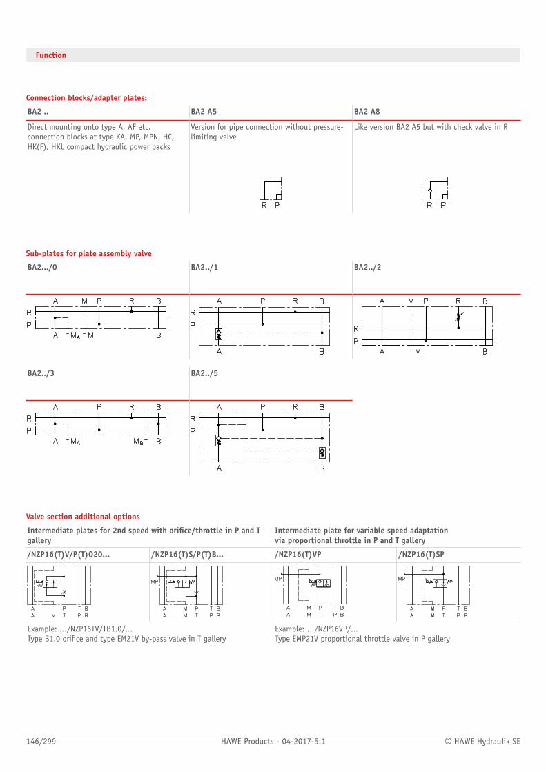
146/299 HAWE Products - 04-2017-5.1 © HAWE Hydraulik SE
Function
Connection blocks/adapter plates:
BA2 .. BA2 A5 BA2 A8
Direct mounting onto type A, AF etc.connection blocks at type KA, MP, MPN, HC,HK(F), HKL compact hydraulic power packs
Version for pipe connection without pressure-limiting valve
Like version BA2 A5 but with check valve in R
Sub-plates for plate assembly valve
BA2.../0 BA2../1 BA2../2
BA2../3 BA2../5
Valve section additional options
Intermediate plates for 2nd speed with orice/throttle in P and Tgallery
Intermediate plate for variable speed adaptation via proportional throttle in P and T gallery
/NZP16(T)V/P(T)Q20... /NZP16(T)S/P(T)B... /NZP16(T)VP /NZP16(T)SP
Example: .../NZP16TV/TB1.0/... Type B1.0 orice and type EM21V by-pass valve in T gallery
Example: .../NZP16VP/... Type EMP21V proportional throttle valve in P gallery

© HAWE Hydraulik SE HAWE Products - 04-2017-5.1 147/299
Intermediate plate (series connection) with pressure-reducingvalve for pressure reduction of the subsequent P gallery
Intermediate plates (parallel connection) with pressure-reducing valve in P gallery
.../CZ... .../NZP16(26)CZ...
Example: BAZ-CZ2/180/5R Type CDK3 pressure-reducing valve set to 180 bar with check valve
Example: .../NZP16CZ08/350/B0.8R/... Type CDK0.8 pressure-reducing valve set to 350 bar with orice andcheck valve in P gallery
Actuations:
M: Solenoid actuation (pmax= 400 bar) P: Pneumatic
GM: Solenoid actuation (pmax= 250 bar) A: Manual actuation
H: Hydraulic actuation T: Pin
K: Roller
End plates
-1 -6 -422 -8 -80/-8W -880(88W)/...
Series withdrain valve
with drain valve andpressure switches
with accumulator portand drain valve
with accumulator portand release valve
with two accumulatorports and release valve
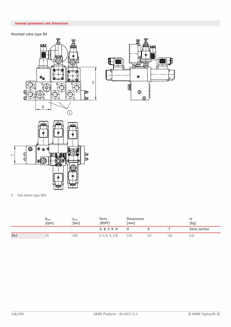
148/299 HAWE Products - 04-2017-5.1 © HAWE Hydraulik SE
General parameters and dimensions
Mounted valve type BA
1 Sub-plates type BA2
Qmax
[lpm]pmax
[bar]Ports(BSPP)
Dimensions [mm]
m[kg]
A, B, P, R, M H B T Valve section
BA2 20 400 G 1/4, G 3/8 139 50 60 0,8

© HAWE Hydraulik SE HAWE Products - 04-2017-5.1 149/299
Associated technical data sheets:■ Valve bank (nominal size 6) type BA:
D 7788■ Intermediate plate type NZP: D 7788 Z
Suitable compact hydraulic power packs:■ See chapter on hydraulic power packs
Suitable connection block:■ Type A: Page 62
Combined products:■ Clamping module type NSMD: D 7787■ Directional spool valves type NSWP:
Page 72■ Directional spool valve type SWPN:
D 7451 AT■ Directional seated valves type NBVP:
Page 134
Suitable accessories:■ Pressure switches type DG: Page 262■ Hydraulic accumulator type AC: Page 258
Suitable plugs:■ Line connector type MSD and others:
D 7163
Circuit example:
HK 449 LDT/1 - Z16 - AL21R F2 - F/50/60 - 7/45
- BA2- NSMD2W/GRK/B2.0/0 - NSMD2W/GRK/B2.0/0 - NSWP2D/B2.0/20/1 - NBVP16G/0- 8 - AC2001/35 - L24
Type HK compact hydraulic power packsize 4; connection block with accumulator charging valve, setting: 50 bar,pressure-limiting valve, setting: 60 bar, lter and pressure switch, setting: 45 bar Parameters of the example circuit:■ QPu = 16 lpm (at 1450 rpm)■ pmax Pu = 110 bar■ pSystem = 60 bar
(pressure-limiting valve setting)■ pswitch-off feature = 50 bar■ Vload = approximately 5 l
Type BA2 valve bank with four industrialstandard valves mounted on sub-plates, twoclamping functions for work piece clampingwith combined option to adjust pressure andpressure switches, two additional functions forindexing and tool clamping

Directional seated valves
150/299 HAWE Products - 04-2017-5.1 © HAWE Hydraulik SE
2.2 Lifting/lowering valve type HSV
Lifting-lowering valves are a combination of directional valves and metering valves.
The valve block type HSV provides the function of a 2/2-way directional seated valve with
electrical actuation for lowering the load. Adjustable throttle valves or ow control valves
independent of the load control the lowering speed. An integrated pressure-limiting valve
limits the permissible load.
The lifting/lowering valve type HSV is used to control lifting equipment with single-acting
cylinders.
Features and benets:■ Optimum control of lifting and lowering function■ High pressures up to 400 bar■ Zero leakage to prevent unwanted lowering of loads and platforms■ Integrated overpressure protection
Intended applications:■ Cranes and lifting equipment■ Materials handling■ Road vehicle■ Mining machinery
Nomen-clature:
Valve combination consisting of:■ 2/2-way directional seated valve,
solenoid actuated■ Pressure-limiting valve■ Check valve optional■ Throttle or 2-way ow control valve
Design: Individual valve for pipe connection
Actuation: Solenoid
pmax: 400 bar
Qmax: 120 l/min
Design and order coding example
HSV 21 - R1 - R-150 - G24
Solenoid voltage 12 V DC, 24 V DC, 110 V AC, 230 V ACHSV 21 and HSV 22 also in explosion-proof version
Pressure limiting valve Manually adjustable or xed, pressure setting in bar
Function
Basic type, size Type HSV, sizes 2 and 7
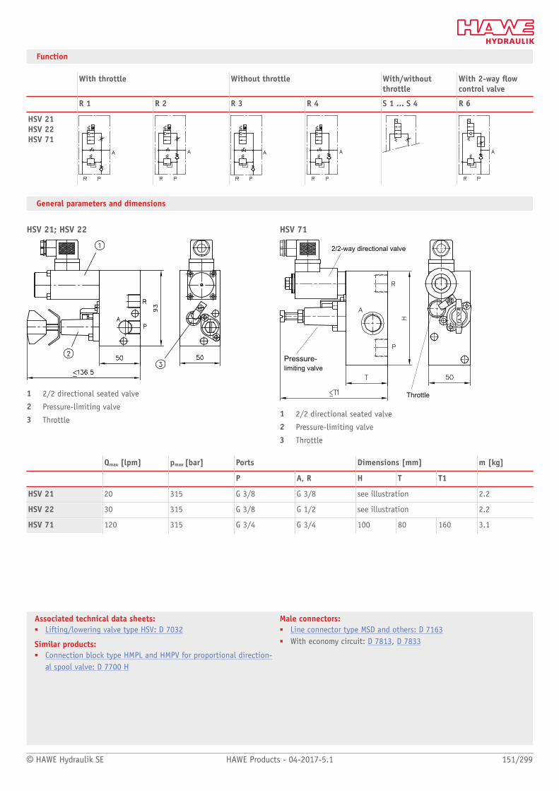
© HAWE Hydraulik SE HAWE Products - 04-2017-5.1 151/299
Associated technical data sheets:■ Lifting/lowering valve type HSV: D 7032
Similar products:■ Connection block type HMPL and HMPV for proportional direction-
al spool valve: D 7700 H
Male connectors:■ Line connector type MSD and others: D 7163■ With economy circuit: D 7813, D 7833
Function
With throttle Without throttle With/withoutthrottle
With 2-way owcontrol valve
R 1 R 2 R 3 R 4 S 1 ... S 4 R 6
HSV 21HSV 22HSV 71
General parameters and dimensions
HSV 21; HSV 22
1 2/2 directional seated valve
2 Pressure-limiting valve
3 Throttle
HSV 71
2/2-way directional valve
Pressure- limiting valve
Throttle
1 2/2 directional seated valve
2 Pressure-limiting valve
3 Throttle
Qmax [lpm] pmax [bar] Ports Dimensions [mm] m [kg]
P A, R H T T1
HSV 21 20 315 G 3/8 G 3/8 see illustration 2.2
HSV 22 30 315 G 3/8 G 1/2 see illustration 2.2
HSV 71 120 315 G 3/4 G 3/4 100 80 160 3.1
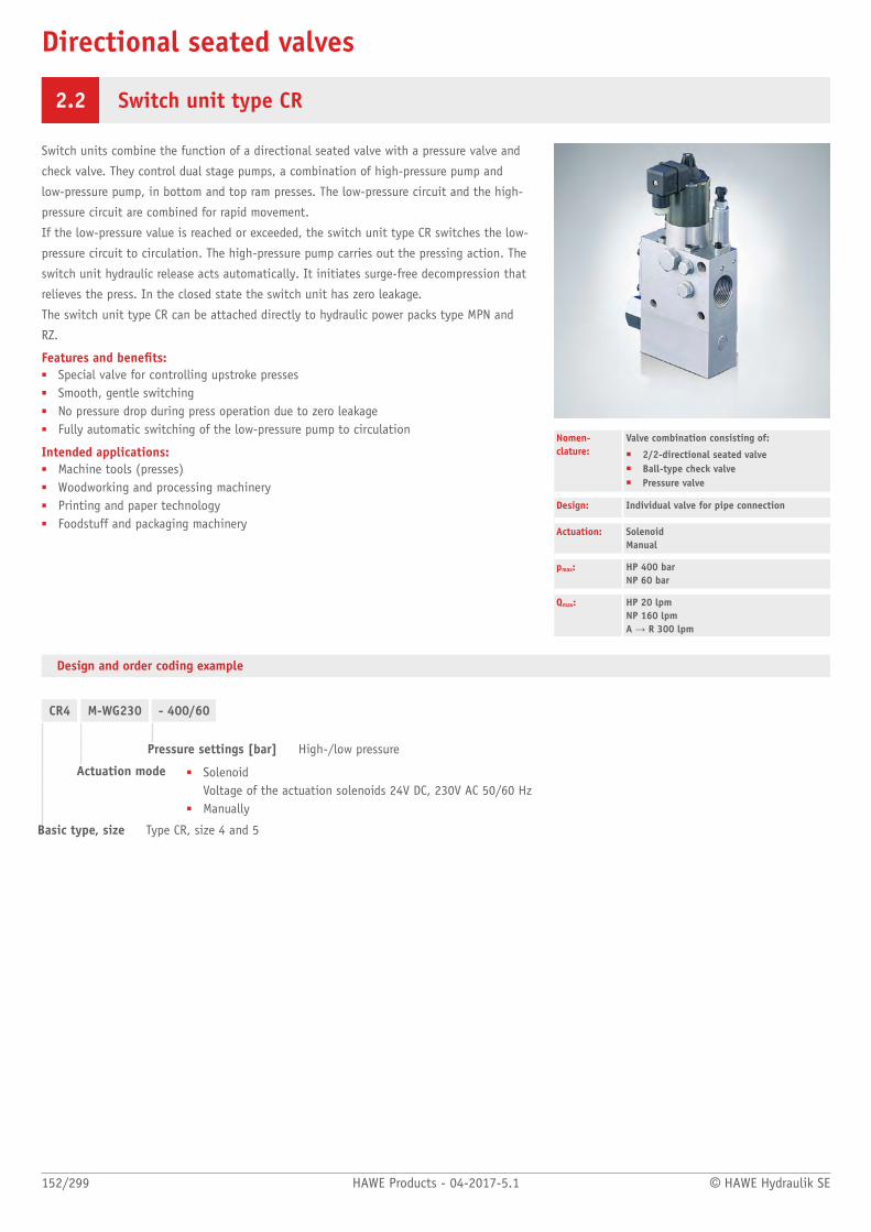
Directional seated valves
152/299 HAWE Products - 04-2017-5.1 © HAWE Hydraulik SE
2.2 Switch unit type CR
Switch units combine the function of a directional seated valve with a pressure valve and
check valve. They control dual stage pumps, a combination of high-pressure pump and
low-pressure pump, in bottom and top ram presses. The low-pressure circuit and the high-
pressure circuit are combined for rapid movement.
If the low-pressure value is reached or exceeded, the switch unit type CR switches the low-
pressure circuit to circulation. The high-pressure pump carries out the pressing action. The
switch unit hydraulic release acts automatically. It initiates surge-free decompression that
relieves the press. In the closed state the switch unit has zero leakage.
The switch unit type CR can be attached directly to hydraulic power packs type MPN and
RZ.
Features and benets:■ Special valve for controlling upstroke presses■ Smooth, gentle switching■ No pressure drop during press operation due to zero leakage■ Fully automatic switching of the low-pressure pump to circulation
Intended applications:■ Machine tools (presses)■ Woodworking and processing machinery■ Printing and paper technology■ Foodstuff and packaging machinery
Nomen-clature:
Valve combination consisting of:
■ 2/2-directional seated valve■ Ball-type check valve■ Pressure valve
Design: Individual valve for pipe connection
Actuation: Solenoid Manual
pmax: HP 400 barNP 60 bar
Qmax: HP 20 lpmNP 160 lpmA → R 300 lpm
Design and order coding example
CR4 M-WG230 - 400/60
Pressure settings [bar] High-/low pressure
Actuation mode ■ Solenoid Voltage of the actuation solenoids 24V DC, 230V AC 50/60 Hz
■ Manually
Basic type, size Type CR, size 4 and 5

© HAWE Hydraulik SE HAWE Products - 04-2017-5.1 153/299
Associated technical data sheets:■ Switch unit type CR: D 7150
Similar products:■ Two-stage valves type NE: Page 192
Hydraulic power packs:■ Compact hydraulic power packs type MP, MPN, MPNW, MPW: Page 50
Male connectors:■ Line connector type MSD and others: D 7163
Function
CR 4M; CR 5M CR 4H
General parameters and dimensions
CR 4M
1 Actuating solenoid
2 Pressure-limiting valve
CR 4H
Qmax
[lpm]pmax
[bar]Ports Dimensions
[mm]m [kg]
HP NP A→R HP NP A and R HP NP M H B T
CR 4M 8 80 200 400 (0) ... 60 G 1 G 1/4 G 3/4 G 1/4 247.5 50 100 5.2
CR 4H 8 80 200 400 (0) ... 60 G 1 G 1/4 G 3/4 G 1/4 202 50 100 4.7
CR 5M 20 160 300 400 (0) ... 60 G 1 1/4 G 3/8 G 1 G 1/4 277.5 63 135 10.0

Directional seated valves
154/299 HAWE Products - 04-2017-5.1 © HAWE Hydraulik SE
2.2 Lifting module type HMT and HST
Lifting modules or hoist control valves are a combination of directional valves and pressure
control valves. They are used to control a lifting function. The ow rate is controlled or
limited proportionally both on lifting and also on lowering.
In the lifting module type HMT and HST directional seated valves are used that ensure the
load is held securely. Two-way ow control valves are used to limit the maximum ow rate.
Valve sections of type SWS can be attached space-savingly to the lifting module to control
additional functions. The lifting module type HMT and HST is suitable for use in industrial
trucks and agricultural machinery.
Features and benets:■ Flexible design for xed or variable displacement pump systems■ Low spatial requirements due to steel design■ Flexible combination with directional valves
Intended applications:■ Materials handling (industrial trucks etc.)■ Cranes and lifting equipment■ Road vehicle
Nomenclature: Valve combination according to type consisting of:
■ 2-way ow control valves■ 2-way seated valves■ Directional spool functions
Design: Valve bank
Actuation: Solenoid
pmax: 315 bar
Qmax: 90 lpm
Design and order coding example
HMT34D - 1/250 - G/MP/0/2 - 31EP - G 24
End plate ■ With two P ports and one R port■ With prop. idle circulation valve■ With solenoid valve for the parking brake
Valve sections, ancillary- and intermediate blocks
Various intermediate blocks for mast tilting, mast shifting, auxiliary hydraulicsDirectional valve sections type SWR 1 with additional functions Directional valve sections type SWS 2
Connection block Pressure setting [bar] of the pressure limiting valve
Additional versions■ Connection blocks type SWR, SWS
■ With ow divider■ With/without pressure limiting valve■ With shut-off valve for P and H (lift)
Basic type Lifting modules and hoist control valves

© HAWE Hydraulik SE HAWE Products - 04-2017-5.1 155/299
Drive concept and application:
Drive concept Application
1 2 Scissor lift Miniature stacker, Walkiestacker
Counter balance truck
Reachtruck
Order picker (warehouse)
no man aloft man aloft
HST x x x x x x x x
HMT x x x x (x)
Drive concepts:■ 1: Constant pump, lifting/lowering via a controller (throttle)■ 2: Lifting via a speed-controlled pump, lowering via a controller (throttle)
Circuit example:
HMT 34-1/200-70F
-G/M/0/2 AN40 BN130
-D/M/0/02
-31E-P12/G 24
Lifting module type HMT, size 3, port size 4 with pressure-limiting valve (set to 200 bar), output controller with 70 l control orice closed in
normal position; segment G with shock and servo-suction valves (set values 40 and 130 bar) in ancillary block; end plate with idle circulation
valve open in neutral position, proportional solenoid voltage for ow control valves 12V DC, solenoid voltage for directional spool valve and
directional seated valves 24V DC
Main lift
Tilting
Adjustment
1 Main stroke
2 Tilt
3 Fork adjustment

156/299 HAWE Products - 04-2017-5.1 © HAWE Hydraulik SE
Function
Lifting modules and connection blocks:
HST HMT
Intermediate blocks (main and initial lift):
Size 2 Size 3
D T2 G/M/DW/2 AN... BN... T2
- Size 2: Hole pattern SWR 1, size 3: Hole pattern SWR 2/SWS 2
End plates:
Size 2 and 3 Size 2 and 3 Size 3 Size 3
1 2 21E 31E
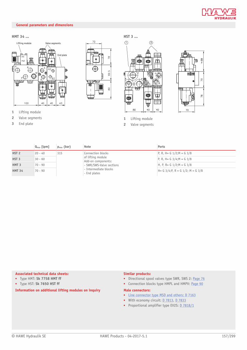
© HAWE Hydraulik SE HAWE Products - 04-2017-5.1 157/299
Associated technical data sheets:■ Type HMT: Sk 7758 HMT ff■ Type HST: Sk 7650 HST ff
Information on additional lifting modules on inquiry
Similar products:■ Directional spool valves type SWR, SWS 2: Page 76■ Connection blocks type HMPL and HMPV: Page 90
Male connectors:■ Line connector type MSD and others: D 7163■ With economy circuit: D 7813, D 7833■ Proportional amplifier type EV2S: D 7818/1
General parameters and dimensions
HMT 34 ...
Lifting module Valve segments
End plate
1 Lifting module
2 Valve segments
3 End plate
HST 3 ...
1 Lifting module
2 Valve segments
Qmax [lpm] pmax (bar) Note Ports
HST 2 20 - 40 P, R, H= G 1/2;M = G 3/8
HST 3 30 - 60 P, R, H= G 3/4;M = G 3/8
HMT 3 70 - 90 H, P, R= G 1/2;M = G 3/8
HMT 34 70 - 90
315 Connection blocks of lifting moduleAdd-on components: - SWR/SWS-Valve sections - Intermediate blocks - End plates
H= G 3/4;P, R = G 1/2; M = G 3/8
Valves
158/299 HAWE Products - 04-2017-5.1 © HAWE Hydraulik SE
2.3 Pressure control valves
Pressure-limiting valve type MV, SV and DMV 162
Pressure control valve type CMV, CMVZ, CSV and CSVZ 166
Pressure-limiting valve, pilot-controlled type DV, AS etc. 168
Sequence valves with check valve type VR 170
Proportional pressure-limiting valve type PMV and PDV 172
Pressure-reducing valve type ADC, ADM, ADME and AM 174
Pressure-reducing valve type ADM and VDM 176
Pressure-reducing valve type CDK, CLK, DK, DLZ and DZ 180
Proportional pressure-reducing valve type PM and PMZ 184
Proportional pressure-reducing valve type PDM 186
Proportional pressure-reducing valve type KFB and FB 188
Pressure-controlled shut-off valve type CNE 190
Two-stage valve type NE 192
Shut-off valve type LV and ALZ 194
Pressure-dependent shut-off valve type DSV and CDSV 196
Load-holding valve type LHK, LHDV and LHT 198
Directly controlled pressure-limiting and
sequence valves type MV, SV
Proportional pressure-limiting valves type PMV and PDV

© HAWE Hydraulik SE HAWE Products - 04-2017-5.1 159/299
Pressure-limiting and sequence valves (also proportional)
Type Design / adjustability pmax
(bar)Qmax
(lpm)
MV, SV, DMV ■ Single valve for pipe connection or manifoldmounting
■ Screw-in valve, installation kit
– Fixed– Adjustable
MVG - 13: 700MVG - 14: 700
MV, SV - 4: 700MV, SV - 5: 700MV, SV - 6: 700MV, SV - 8: 700
DMV - 4: 350DMV - 5: 350DMV - 6: 350DMV - 8: 315
MVG - 13: 8MVG - 14: 8
MV, SV - 4: 20MV, SV - 5: 40MV, SV - 6: 70MV, SV - 8: 160
DMV - 4: 20DMV - 5: 40DMV - 6: 75DMV - 8: 160
CMV(Z), CSV(Z) ■ Screw-in valve
– Fixed– Adjustable
CMV - 1: 500CMV - 2: 500CMV - 3: 500
CSV - 2: 315CSV - 3: 315
CSVZ - 2: 315
CMVZ - 2: 500
CMV - 1: 20CMV - 2: 40CMV - 3: 60
CSV - 2: 40CSV - 3: 60
CSVZ - 2: 40
CMVZ - 2: 40
DV, AS ■ Single valve for pipe connection or manifoldmounting
– Fixed– Adjustable
DV - 3: 420DV - 4: 420DV - 5: 420
AS - 3: 350AS - 4: 350AS - 5: 350
DV - 3: 40DV - 4: 80DV - 5: 120
AS - 3: 50AS - 4: 80AS - 5: 120
VR ■ Insert valve■ Housing version
– Fixed
1: 3152: 3153: 3154: 315
1: 152: 403: 654: 120
PMV, PDV ■ Single valve for pipe connection or manifoldmounting
– Electro-proportional
PMV - 4: 700PMV - 5: 450PMV - 6: 320PMV - 8: 180
PDV - 3: 350PDV - 4: 350PDV - 5: 350
PMV - 4: 16PMV - 5: 60PMV - 6: 75PMV - 8: 120
PDV - 3: 40PDV - 4: 80PDV - 5: 120

160/299 HAWE Products - 04-2017-5.1 © HAWE Hydraulik SE
Pressure reducing valves (also proportional)
Type Design / adjustability pmax/pA
(bar)Qmax
(lpm)
ADC, ADM, ADME, AM
■ Screw-in valve■ For pipe connection
– Fixed
ADC 1: 300/25
ADM 1: 315/70
ADME 1: 315/70
AM 1: 400/100
ADC 1: 2
ADM 1: 10
ADME 1: 8
AM 1: 2
ADM, VDM
■ Single valve for pipe connection or manifoldmounting
■ Directly controlled or pilot-controlled
– Fixed– Adjustable
ADM 1: 315/70ADM 11: 320/250ADM 21: 320/250ADM 22: 320/250ADM 32: 320/250ADM 33: 320/250
VDM 3: 400/300VDM 4: 400/300VDM 5: 400/300
ADM 1: 10ADM 11: 12ADM 21: 25ADM 22: 25ADM 32: 60ADM 33: 60
VDM 3: 40VDM 4: 70VDM 5: 120
CDK, CLK, DK, DLZ, DZ
■ Screw-in valve according to the 2-way principle■ Combination with connection block
– Fixed– Adjustable
CDK - 3: 500/450
CLK - 3: 500/450
DLZ - 3: 400/380
DK - 3: 500/450
DZ - 3: 500/450
CDK - 3: 22
CLK - 3: 22
DLZ - 3: 22
DK - 3: 22
DZ - 3: 22
PM, PMZ
■ Installation kit■ Individual valve for manifold mounting
– Electro-proportional
PM - 1: 40/30PM - 11: 40/30PM - 12: 40/30PM - 22: 40/30
PMZ - 1: 40/30
PM - 1: 2PM - 11: 2PM - 12: 2PM - 22: 2
PMZ - 1: 2
PDM
■ Single valve for pipe connection or manifoldmounting
– Electro-proportional
11: 320/32012: 320/32021: 320/18022: 320/1803: 350/3504: 350/3505: 350/350
11: 1212: 1221: 2022: 203: 404: 805: 120
KFB, FB■ Single valve for pipe connection
– Manual
01: 120/30 01: 2
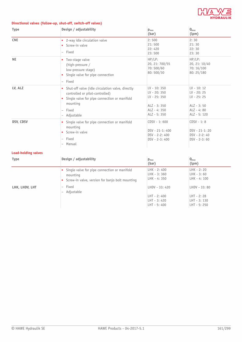
© HAWE Hydraulik SE HAWE Products - 04-2017-5.1 161/299
Directional valves (follow-up, shut-off, switch-off valves)
Type Design / adjustability pmax
(bar)Qmax
(lpm)
CNE ■ 2-way idle circulation valve■ Screw-in valve
– Fixed
2: 50021: 50022: 42023: 500
2: 3021: 3022: 3023: 30
NE ■ Two-stage valve(high-pressure /low-pressure stage)
■ Single valve for pipe connection
– Fixed
HP/LP:20, 21: 700/5570: 500/6080: 500/30
HP/LP:20, 21: 10/4070: 16/10080: 25/180
LV, ALZ ■ Shut-off valve (idle circulation valve, directlycontrolled or pilot-controlled)
■ Single valve for pipe connection or manifoldmounting
– Fixed– Adjustable
LV - 10: 350LV - 20: 350LV - 25: 350
ALZ - 3: 350ALZ - 4: 350ALZ - 5: 350
LV - 10: 12LV - 20: 25LV - 25: 25
ALZ - 3: 50ALZ - 4: 80ALZ - 5: 120
DSV, CDSV ■ Single valve for pipe connection or manifoldmounting
■ Screw-in valve
– Fixed– Manual
CDSV - 1: 600
DSV - 21-1: 400DSV - 2-2: 400DSV - 2-3: 400
CDSV - 1: 8
DSV - 21-1: 20DSV - 2-2: 40DSV - 2-3: 60
Load-holding valves
Type Design / adjustability pmax
(bar)Qmax
(lpm)
LHK, LHDV, LHT
■ Single valve for pipe connection or manifoldmounting
■ Screw-in valve, version for banjo bolt mounting
– Fixed– Adjustable
LHK - 2: 400LHK - 3: 360LHK - 4: 350
LHDV - 33: 420
LHT - 2: 400LHT - 3: 420LHT - 5: 400
LHK - 2: 20LHK - 3: 60LHK - 4: 100
LHDV - 33: 80
LHT - 2: 28LHT - 3: 130LHT - 5: 250

Pressure control valves
162/299 HAWE Products - 04-2017-5.1 © HAWE Hydraulik SE
2.3 Pressure-limiting valve type MV, SV and DMV
Pressure-limiting valves and sequence valves are types of pressure control valves. Pressure-
limiting valves safeguard the system against excessive system pressure or limit the
operation pressure. Sequence valves generate a constant pressure difference between the
inlet and outlet ow.
Type MV and SV is a directly controlled valve that is damped as standard. Versions that
correspond to the Pressure Equipment Directive are also available.
Features and benets:■ Operating pressures up to 700 bar■ Various adjustment options■ Numerous configurations
Intended applications:■ General hydraulic systems■ Test benches■ Hydraulic tools
Nomen-clature:
Pressure-limiting valve,sequence valve (directly controlled)
Design: Individual valve for pipe connection Screw-in valve Individual manifold mounting valve Assembly kit
Adjustment: Fixed Manually adjustable
pmax: 700 bar
Qmax: 160 lpm
Design and order coding example
MVS 52 B R X - 650
Pressure setting ]
Optionally without dampening (X)
Adjustability (while pressurized) ■ xed■ Manually adjustable■ Adjustable with turn knob (self-locking/lockable)
Pressure range and volumetric ow Pressure ranges A, B, C, E and F
Basic type, size Type MV.., DMV.. and SV..
Additional versions■ Pressure-limiting valves with unit approval (TÜV valves) (type MVX, MVSX, MVEX, MVPX, SVX,
size 4, 5 and 6)■ Various actuations: ball head for controls via cam, lever etc. (type MVG and MVP only)
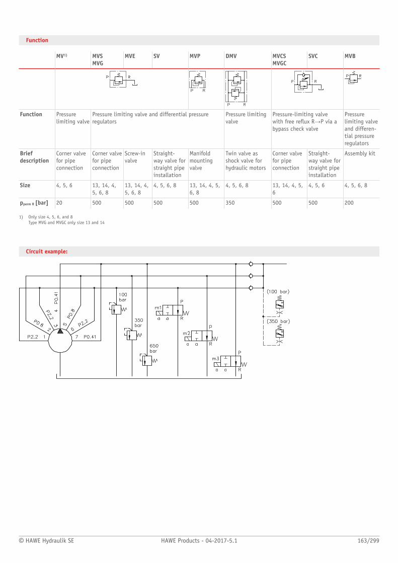
© HAWE Hydraulik SE HAWE Products - 04-2017-5.1 163/299
Function
MV1) MVSMVG
MVE SV MVP DMV MVCSMVGC
SVC MVB
Function Pressurelimiting valve
Pressure limiting valve and differential pressureregulators
Pressure limitingvalve
Pressure-limiting valvewith free reux R→P via abypass check valve
Pressurelimiting valveand differen-tial pressureregulators
Briefdescription
Corner valvefor pipeconnection
Corner valvefor pipeconnection
Screw-invalve
Straight-way valve forstraight pipeinstallation
Manifoldmountingvalve
Twin valve asshock valve forhydraulic motors
Corner valvefor pipeconnection
Straight-way valve forstraight pipeinstallation
Assembly kit
Size 4, 5, 6 13, 14, 4,5, 6, 8
13, 14, 4,5, 6, 8
4, 5, 6, 8 13, 14, 4, 5,6, 8
4, 5, 6, 8 13, 14, 4, 5,6
4, 5, 6 4, 5, 6, 8
pperm R [bar] 20 500 500 500 500 350 500 500 200
1) Only size 4, 5, 6, and 8Type MVG and MVGC only size 13 and 14
Circuit example:

164/299 HAWE Products - 04-2017-5.1 © HAWE Hydraulik SE
General parameters and dimensions
MV, MVS DMV
MVG SV, SVC
See following table for dimensions

© HAWE Hydraulik SE HAWE Products - 04-2017-5.1 165/299
Associated technical data sheets:■ Pressure-limiting valve type MV, SV and DMV: D 7000/1■ Pressure-limiting valve and pre-load valve type MVG, MVE and
MVP: D 3726■ Pressure-limiting valve (installation kit) type MV: D 7000 E/1■ Multiple pressure-limiting valve type MV: D 7000 M■ Pressure-limiting valve, with unit approval type MV .X: D 7000 TUV
Similar products:■ Pressure control valves for screwing in type CMV, CSV: Page 166■ Pilot-controlled pressure control valves type DV: Page 168■ Pilot-controlled pressure control valves type A: Page 168
Size Dimensions [mm]
m[kg]
Size Pressure range/Flow
Ports1)
Hmax B/SW Tmax
4 126 24 48 0.3
5 142 29 60 0.4
6 164 36 70 0.7
MV, MVS, MVCS, MVE
8 208 40 60 2.0
4 F: 80/20 E: 160/20 C: 315/20 B: 500/20 A: 700/12
G 1/4, G 3/8
4 107 40 52 0.7
5 123 50 65 1.3
6 142.5 60 75 1.8
DMV
8 192 80 96 4.5
5 F: 80/40 E: 160/40 C: 315/40 B: 500/40 A: 700/20
G 3/8, G 1/2
4 102 28 35 0.3
5 113 32 40 0.5
6 133 35 50 0.8
8 172 50 60 1.6
6 F: 80/75 E: 160/75 C: 315/75 B: 500/75 A: 700/40
G 1/2 G 3/4MVP
13, 14 82 29 50 0.3
MVE 13, 14 75 SW 27 - 0.1
8 E: 160/160 C: 315/160Bi: 500/160A: 700/75
G 3/4, G 1
MVG, MVGC 13, 14 94 20 42 0.3 13 H: 700/5 G 1/4
4 - SW 22 87 0.2
5 - SW 27 108 0.4
SV, SVC
6 - SW 32 132 0.9
SV 8 - SW 41 157 0.9
14 N: 50/8 M: 200/8 H: 400/8
G 1/4
1) For pipe connection versions only
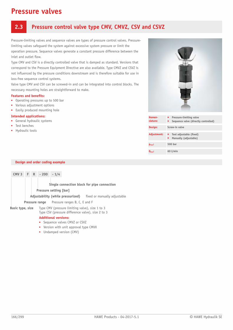
Pressure valves
166/299 HAWE Products - 04-2017-5.1 © HAWE Hydraulik SE
2.3 Pressure control valve type CMV, CMVZ, CSV and CSVZ
Pressure-limiting valves and sequence valves are types of pressure control valves. Pressure-
limiting valves safeguard the system against excessive system pressure or limit the
operation pressure. Sequence valves generate a constant pressure difference between the
inlet and outlet ow.
Type CMV and CSV is a directly controlled valve that is damped as standard. Versions that
correspond to the Pressure Equipment Directive are also available. Type CMVZ and CSVZ is
not inuenced by the pressure conditions downstream and is therefore suitable for use in
loss-free sequence control systems.
Valve type CMV and CSV can be screwed-in and can be integrated into control blocks. The
necessary mounting holes are straightforward to make.
Features and benets:■ Operating pressures up to 500 bar■ Various adjustment options■ Easily produced mounting hole
Intended applications:■ General hydraulic systems■ Test benches■ Hydraulic tools
Nomen-clature:
■ Pressure-limiting valve■ Sequence valve (directly controlled)
Design: Screw-in valve
Adjustment: ■ Tool adjustable (xed)■ Manually (adjustable)
pmax: 500 bar
Qmax: 60 l/min
Design and order coding example
CMV 3 F R - 200 - 1/4
Single connection block for pipe connection
Pressure setting [bar]
Adjustability (while pressurized) xed or manually adjustable
Pressure range Pressure ranges B, C, E and F
Basic type, size Type CMV (pressure limiting valve), size 1 to 3 Type CSV (pressure difference valve), size 2 to 3
Additional versions:■ Sequence valves CMVZ or CSVZ■ Version with unit approval type CMVX■ Undamped version (CMV)
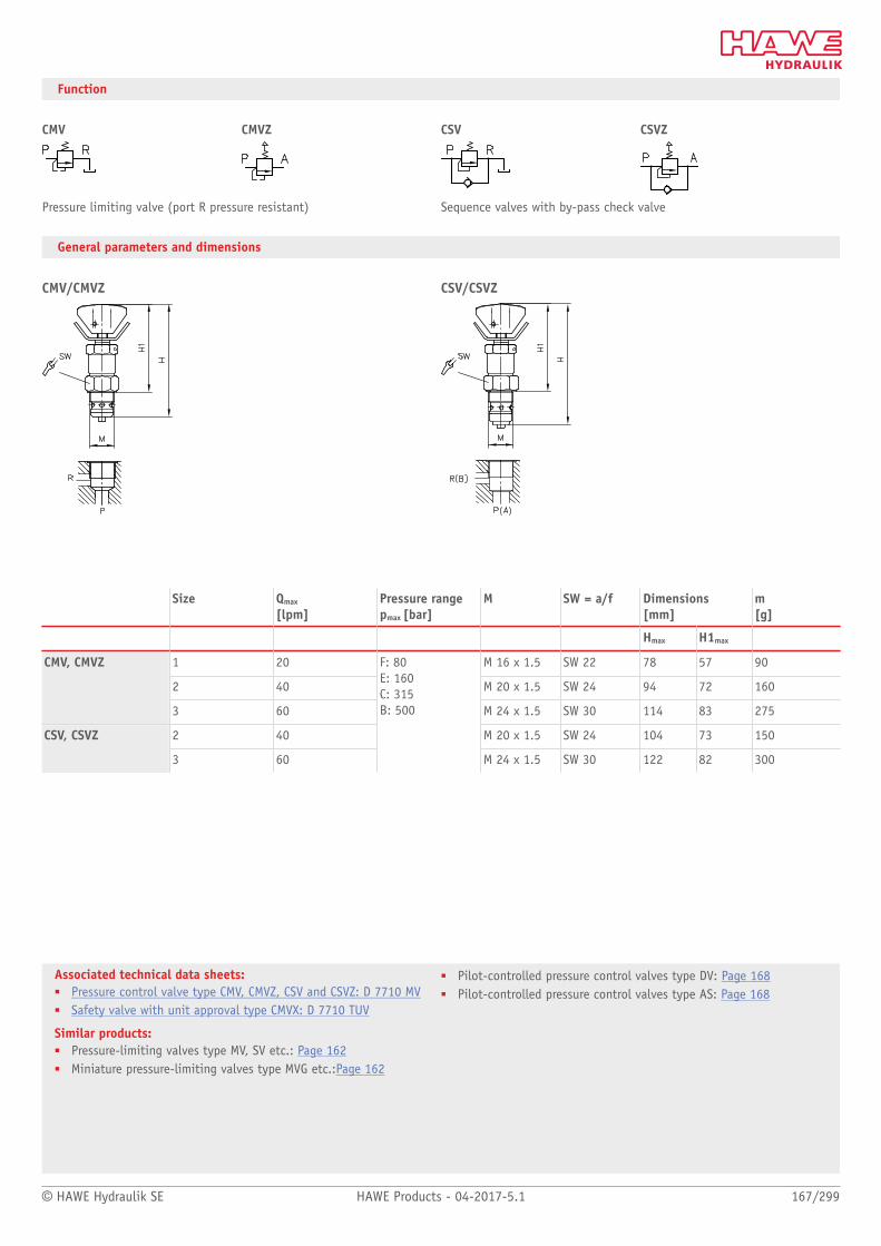
© HAWE Hydraulik SE HAWE Products - 04-2017-5.1 167/299
Associated technical data sheets:■ Pressure control valve type CMV, CMVZ, CSV and CSVZ: D 7710 MV■ Safety valve with unit approval type CMVX: D 7710 TUV
Similar products:■ Pressure-limiting valves type MV, SV etc.: Page 162■ Miniature pressure-limiting valves type MVG etc.:Page 162
■ Pilot-controlled pressure control valves type DV: Page 168■ Pilot-controlled pressure control valves type AS: Page 168
Function
CMV CMVZ CSV CSVZ
Pressure limiting valve (port R pressure resistant) Sequence valves with by-pass check valve
General parameters and dimensions
CMV/CMVZ CSV/CSVZ
Size Qmax
[lpm]Pressure rangepmax [bar]
M SW = a/f Dimensions[mm]
m[g]
Hmax H1max
1 20 M 16 x 1.5 SW 22 78 57 90
2 40 M 20 x 1.5 SW 24 94 72 160
CMV, CMVZ
3 60 M 24 x 1.5 SW 30 114 83 275
2 40 M 20 x 1.5 SW 24 104 73 150CSV, CSVZ
3 60
F: 80 E: 160 C: 315 B: 500
M 24 x 1.5 SW 30 122 82 300

Pressure valves
168/299 HAWE Products - 04-2017-5.1 © HAWE Hydraulik SE
2.3 Pressure-limiting valve, pilot-controlled type DV, AS etc.
Pressure-limiting valves are a type of pressure control valve. They safeguard the system
against excessive system pressure or limit the operation pressure.
The pressure-limiting valve type DV and AS is pilot-controlled. Type AS also has an
additional check valve in the consumer port.
Features and benets:■ Various adjustment options■ Various additional functions
Intended applications:■ General hydraulic systems■ Test benches
Nomen-clature:
Pressure-limiting valveSequence valveSwitch-off/release valve (pilot-controlled)
Design: Single valve for pipe connectionIndividual valve for manifold mounting
Adjustment: Tool adjustable (xed)Manually (adjustable)
pmax: 420 bar
Qmax: 120 l/min
Design and order coding example
DV3 G H R - WN 1F- 24 - 200
Pressure setting [bar]
2/2-way directional seated valve Optionally with mounted 2/2-way directional seated valve for arbitrary idle circulation
Adjustability in operation xed or manually adjustable (R)
■ Various actuations for the pilot valve: ball head for controls via cam, lever etc. (type DV, DVE)
Pressure range ■ N: 2 to 100 bar■ H: 5 to 420 bar
Line connection Pipe connection or manifold mounting
Basic type, size Type DV (internal control oil drain), Type DVE (external control oil drain), Type DF (valve for remote control), size 3 to 5Type AS (additional check valve), size 3 to 5Type AE (release valve), size 3 to 5
Additional versions:■ Additional switching combinations with the types AS and AE

© HAWE Hydraulik SE HAWE Products - 04-2017-5.1 169/299
Associated technical data sheets:■ Pressure-limiting valve, pilot-controlled type DV, DVE and DF:
D 4350■ Pressure valve with check valve type AL, AE and AS: D 6170
Similar products:■ Pressure-limiting valves type MV, SV etc.: Page 162■ Miniature pressure-limiting valves type MVG etc.: Page 162■ Pressure-limiting valves type CMV(Z): Page 166
Function
DV DVE DF AS AE
Pressure limiting, sequence valve
Follow-up valve Pressure limiting, sequence valve, follow-up valve or 2/2-waydirectional valve (remotecontrolled, depending on the kindof valve connected to port X)
Pressure limiting valve Release valve (remotecontrolled), combined function aspressure limiting valve possible(type ASE)
General parameters and dimensions
DV .. Gc ju m u y w y
1 Pilot valve (can be adjusted
manually)
2 2/2-way solenoid valve (option)
DV .. Pa x d
1 Pilot valve (xed)
AS .. G
1 Pilot valve
AS .. PPilot valve
1 Pilot valve
Type, size Qmax
[lpm]Pressure range:pmax [bar]
Ports Dimensions [mm]
m[kg]
DV, DVE, DF H B B1 T T1
3 50 G 1/2 30 60 - 66 - 1,1 / -
4 80 G 3/4 40 65 60 71 78 1,5 / 2,0
5 120
N: 100 H: 420
G 1 50 80 88 73 81 2,0 / 2,5
Type, size Qmax
[lpm]Pressure range:pmax [bar]
Ports Dimensions [mm]
m[kg]1)
AS, ASE, AE H H1 B B1 T T1
3 50 G 1/2 40 - 60 - 80 - 1,8
4 80 G 3/4 40 40 70 80 94 60 2,2
5 120
M: 200 H: 350/300 (type AE)
G 1 6,3 40 100 94 85 80 4,1
1) Versions for pipe connection/manifold mounting (with installed solenoid valve + 0.6 kg)

Pressure valves
170/299 HAWE Products - 04-2017-5.1 © HAWE Hydraulik SE
2.3 Sequence valves with check valve type VR
Pre-load valves, also called sequence valves are a type of pressure control valve. They
generate a largely constant pressure drop between the inlet and outlet on the valve. In
the opposite direction the ow can pass freely. In the normal position the valve has minor
leakage.
The sequence valve type VR is available as a screw-in valve and in a housing version for in-
line installation.
The primary application area is in return lines for oscillation damping, mainly in lifting
equipment, lifting platforms, handling systems and in lifting gantries as fall protection.
Features and benets:■ Compact screw-in valve
Intended applications:■ Lifting equipment■ Lifting platforms■ Handling technology
Nomen-clature:
Sequence valve
Design: Screw-in valve Combination with housing for pipeconnection
Adjustment: Fixed (non-adjustable)
pmax:Δpmax:
315 bar15 bar
Qmax: 120 l/min
Design and order coding example
VR 3 3 C
Design with housing ■ Cartridge valve■ Versions with housing for pipe connection■ Design with metric ne thread
Pre-load pressure Open-up pressure Δpmax 3 to 15 bar
Basic type, size Type VR, size 1 to 4

© HAWE Hydraulik SE HAWE Products - 04-2017-5.1 171/299
Associated technical data sheets:■ Pre-load check valve type VR: D 7340
Similar products:■ Pressure-limiting valves type MV, SV etc.: Page 162■ Miniature pressure-limiting valves type MVG etc.: Page 162■ Pilot-controlled pressure control valves type DV: Page 168■ Pressure-limiting valves type CMV: Page 166
Function
VR
Screw-in valve Version with housing for pipe connection
General parameters and dimensions
VR 3 3 CInsert valve
VR 4 9 EVersion with housing
VR 1 15 GVersion with housing
Qmax
[lpm]Δpmax
[bar] 1)Dimensions[mm]
m[g]2)
G (BSPP) L L1 L2 SW = a/f
VR 1 15 3, 5, 7, 9, 12, 15 G 1/4 (A) 31 78 66 SW 19 15/120
VR 2 40 3, 5, 7, 9, 12, 15 G 3/8 (A) 36 82 70 SW 22 25/160
VR 3 65 3, 5, 7, 9, 12 G 1/2 (A) 42 96 80 SW 27 40/270
VR 4 120 3, 5, 7, 9, 12 G 3/4 (A) 54 106 100 SW 32 80/400
1) The selected pre-load pressure e.g. opening pressure cannot beltered2) Individual valve/design with housing

Pressure valves
172/299 HAWE Products - 04-2017-5.1 © HAWE Hydraulik SE
2.3 Proportional pressure-limiting valve type PMV and PDV
Proportional pressure-limiting valves are a type of pressure control valve. They remotely
control the pressure in hydraulic systems continuously and electrically.
The pressure-limiting valve type PMV is a directly actuated valve in a spring-loaded ball
version. The pressure can be set to up to 700 bar. The pressure-limiting valve type PDV is
a pilot valve in a piston version, where pressures up to 350 bar can be set. The pressure-
limiting valve type PMV and PDV is available as a single valve for pipe connection or as a
manifold mounting valve.
The proportional pressure-limiting valve is particularly suitable for maximum pressure
limitation in hydraulic systems.
Features and benets:■ Max. operating pressure 700 bar■ Precise control
Intended applications:■ General hydraulics■ Test benches■ Mining machinery
Nomen-clature:
Prop. pressure-limiting valve (directly controlled or piloted)
Design: Individual valve for pipe connection Individual valve Manifold mounting
Adjustment: Electro-proportional
pmax: 700 bar
Qmax: 120 l/min
Design and order coding example
PDV4GPMVP4
H- 44
- G24- G24
Solenoid voltage Prop. solenoid
■ 12V DC, 24V DC■ Control using proportional amplifier or PLVC
Pressure range [bar]
Basic type, port size, size Type PMV (pipe connection), type PMVP (manifold mounting)
■ Optionally with separate control oil supply, i.e. pressure reduction right above 0 bar, zero-leakage in the mainpump circuit (type PMVS, PMVPS)
Type PDV.G (pipe connection), type PDV.P (manifold mounting)
■ Additionally with 2/2-way solenoid valves for arbitrary idle circulation
Function
PMV, PDV
Pipe connection Manifold mounting valve

© HAWE Hydraulik SE HAWE Products - 04-2017-5.1 173/299
Associated technical data sheets:■ Proportional pressure-limiting valve type PMV and PMVP:
D 7485/1■ Proportional pressure-limiting valve type PDV and PDM: D 7486■ Proportional pressure-limiting valve type NPMVP: D 7485 N■ Intermediate plate type NZP: D 7788 Z
Suitable accessories:■ Proportional amplifier type EV1M3: Page 272■ Proportional amplifier type EV2S: "CAN-IO, EV2S-CAN"■ Proportional amplifier type EV1D: Page 272
General parameters and dimensions
PMV PDV..G
PMVP PDV..P
Size Qmax[lpm] Pressure range pmax [bar] Ports 1) Dimensions [mm] m [kg]
H B T
4 16 41: 180 42: 290 43: 440 44: 700
G 1/4, G 3/8 97/95 35 135 1,2 / 1,1
5 60 41: 110 42: 180 43: 270 44: 450
G 1/4, G 3/8, G 1/2 98/95 35/40 140 1.2
6 75 41: 80 42: 130 43: 190 44: 320
G 3/8, G 1/2, G 3/4 102/95 40/50 150/140 1,5/1,3
PMV/PMVP
8 120 41: 45 42: 70 43: 110 44: 180
G 3/4, G 1 107/97 45/60 160/150 1,9/1,7
3 40 G 1/2 96 66 150 1.8
4 80 G 3/4 99.5 71/78 155/150 2,2/2,7
PDV.G/PDV.P
5 120
N: 130 M: 200 H: 350
G 1 104.5 73/81 170/178 2.7/3.2
1) For pipe connection versions only

Pressure valves
174/299 HAWE Products - 04-2017-5.1 © HAWE Hydraulik SE
2.3 Pressure-reducing valve type ADC, ADM, ADME and AM
Pressure reducing valves are a type of pressure control valve. They maintain a largely
constant outlet pressure even at a variable (higher) inlet pressure.
The pressure reducing valve type ADC and AM is suitable for the supply of control circuits
with low oil consumption. These valves feature an override compensation, i.e. acting like
a pressure-limiting valve if the secondary pressure exceeds the set pressure e.g. due to
external forces. There is a design-related leakage ow.
Features and benets:■ Compact design■ Numerous configurations
Intended applications:■ For control oil supply in pilot circuits
Nomen-clature:
Pressure reducing valve
Design: Screw-in valve Valve for pipe connection
Adjustment: Fixed (non-adjustable)
pmax P: 400 bar
pmax A: 100 bar
Qmax: 10 lpm
Design and order coding example
ADC 1 - 25 - 1/4
Design ■ Cartridge valve■ Design with housing for direct pipe connection■ Version with housing for manifold mounting (type AM 11)
Pressure downstream Pressure at port A [bar]
Basic type Type ADC, AM Type ADM, ADME
■ Type ADM 1 adjustable version available
Function
ADC, AM, ADM, ADME
Screw-in valve Pipe installation

© HAWE Hydraulik SE HAWE Products - 04-2017-5.1 175/299
Associated technical data sheets:■ Pressure-reducing valve type ADC, ADM, ADME and AM: D 7458
Similar products:■ Pressure reducing valves type ADM, VDM: Page 176■ Pressure reducing valves type CDK: Page 180
■ Prop. pressure reducing valves type PDM: Page 186■ Miniature prop. pressure reducing valves type PM, PMZ: Page 184
General parameters and dimensions
ADC 1 - 25 AM 1 - 20 - 1/4 ADME 1 - ... ADM 1 - 70Pressure reducing valve typeADC 1 as screw-in valve, pressure at A (on theconsumer side) approx.25 bar
Pressure reducing valve type AM 1, version for pipe connection (threadedconnections G 1/4), pressure at A (on theconsumer side) approx. 20 bar
Pressure reducing valve type ADM 1, version for pipe connection,pressure at A (on the consumer side)approx. 70 bar
Qmax
[lpm]pmax
[bar]Outlet pressure[bar] at A
Ports 1) mmax
[kg]
Screw-in valve Pipe installation
ADC 1 2 300 15, 25 G 1/4 0.03 0.32
AM 1 2 400 20, 30, 40, 100 G 1/4 0.03 0.3
ADM 1 8 ... 10 300 15, 20, 30, 70 G 1/4 - 0.34
ADME 8 300 15, 20, 30 - 0.05 -
1) In version for pipe connection only

Pressure valves
176/299 HAWE Products - 04-2017-5.1 © HAWE Hydraulik SE
2.3 Pressure-reducing valve type ADM and VDM
Pressure reducing valves are a type of pressure control valve. They maintain a largely
constant outlet pressure even at a variable (higher) inlet pressure.
The pressure reducing valve type ADM is directly controlled, the type VDM is hydraulically
pilot-controlled. These valves feature an override compensation, i.e. acting like a pressure-
limiting valve if the secondary pressure exceeds the set pressure e.g. due to external forces.
There is a design-related leakage ow.
Features and benets:■ With safety valve function■ Various adjustment options■ Various additional functions
Intended applications:■ General hydraulics■ Jigs■ Test benches
Nomen-clature:
Pressure reducing valve(directly-controlled or pilot-controlled)
Design: Single valve for pipe connectionIndividual valve for manifold mounting
Adjustment: Tool adjustable (xed)Manually (adjustable)
pmax P: 400 bar
pmax A: 300 bar
Qmax: 120 l/min
Design and order coding example
ADM 22 D R - 250
Pressure setting [bar]
Adjustability in operation ■ Fixed (-)■ Manually adjustable (R)■ Adjustable with turn knob (self-locking -V/lockable -H)
Pressure range Pressure ranges for outlet pressure at A
Basic type, size Type ADM (non-piloted), size 1 to 3
VDM 5 H R - 250
Pressure setting [bar]
Adjustability in operation ■ Fixed (-)■ Manually adjustable (R)
Pressure range Pressure ranges for outlet pressure at A
Basic type, size Type VDM (hydraulically piloted), size 3 to 5
■ Hydraulically piloted pressure-reducing valve type VDX (pressure-limiting valve at port L)

© HAWE Hydraulik SE HAWE Products - 04-2017-5.1 177/299
Function
ADM.. VDM..
Valve for pipe connection Manifold mounting valve Valve for pipe connection Manifold mounting valve
General parameters and dimensions
ADM 22 DR ADM...PVersion for pipe connectionDirectly controlled pressure reducing valve type ADM, size 2 for pipe connection (threaded connections G 3/8, coding 2), pressure range 30 to 120 bar (coding D), manually adjustable pressure (coding R)
Version as manifold mounting valve

178/299 HAWE Products - 04-2017-5.1 © HAWE Hydraulik SE
VDM...G VDM 5 PH - 250Version for pipe connection Version as manifold mounting valve
Pilot-controlled pressure reducing valve type VDM, size 5 for manifold mounting (coding P), pressure range 10 to 400 bar (coding H), pressure xed at 250 bar
1 Pilot valve
Pilot valve
1 Pilot valve
Qmax
[lpm]pmax
[bar]pmax A
[bar]Ports 2) Leakage ow Q
leak [lpm]Dimensions [mm]
mmax
[kg] 3)
H H1 B B1 T T1
ADM 1... 12 G 1/4 <0.05 30 35 45 35 141 - 0.6/0.6
ADM 2.. 25
F: 30D: 120C: 160A: 250
G 1/4, G 3/8 <0.05 30 40 50 40 162 - 0.7/0.85
ADM 3.. 60
300
F: 25D: 100C: 160A: 250
G 3/8, G 1/2 <0.07 30 40 50 40 174 - 1.0/1.1
VDM 3.. 40 G 1/2 30 - 60 - 66 - 1.1/--
VDM 4.. 70 G 3/4 40 40 65 60 71 78 1.5/2.0
VDM 5.. 120
400 N: 100H: 4001)
G 1
<0.4
50 50 80 88 73 81 2.0/2.5
1) Max. pressure difference between inlet and outlet pressure is 300 bar2) For pipe connection versions only3) Versions for pipe connection / manifold mounting
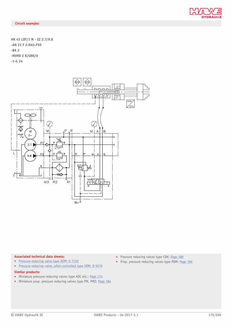
© HAWE Hydraulik SE HAWE Products - 04-2017-5.1 179/299
Associated technical data sheets:■ Pressure-reducing valve type ADM: D 7120■ Pressure-reducing valve, pilot-controlled type VDM: D 5579
Similar products:■ Miniature pressure reducing valves type ADC etc.: Page 174■ Miniature prop. pressure reducing valves type PM, PMZ: Page 184
■ Pressure reducing valves type CDK: Page 180■ Prop. pressure reducing valves type PDM: Page 186
Circuit example:
HK 43 LDT/1 M - ZZ 2.7/9.8
-AN 21 F 2-D45-F50
-BA 2
-NSMD 2 K/GRK/0
-1-G 24

Pressure valves
180/299 HAWE Products - 04-2017-5.1 © HAWE Hydraulik SE
2.3 Pressure-reducing valve type CDK, CLK, DK, DLZ and DZ
Pressure reducing valves are a type of pressure control valve. They maintain a largely
constant outlet pressure even at a variable (higher) inlet pressure.
The pressure reducing valve type CLK features an override compensation, i.e. acting like
a pressure-limiting valve if the secondary pressure exceeds the set pressure e.g. due to
external forces. The pressure reducing valve type DK features a tracked pressure switch, e.g.
pressure and switch are set simultaneously with an adjustment device.
All versions have zero leakage when in the closed state. The valve type CDK and CLK can
be screwed-in and can be integrated into control blocks. The necessary mounting holes are
straightforward to make.
Features and benets:■ Zero leakage in closed state
Intended applications:■ General hydraulic systems■ Jigs■ Test benches
Nomen-clature:
Pressure reducing valve (2-way valve)
Design: Screw-in valve combination with a connectionblock for
■ Pipe connection■ Manifold mounting
Adjustment: FixedManually (adjustable)
pmax: 500 bar
Qmax: 22 l/min
Design and order coding example
CDK 3 -2 R - 250
Pressure setting [bar]
Adjustment ■ Fixed (-)■ Manually adjustable (R)■ Adjustable with turn knob (self-locking -V/lockable -H)
Basic type and pressure range Type CDK, type CLK (with additional override compensation)
■ Screw-in valve■ Version with connection block for pipe connection with/without pressure-limiting valve■ Version with connection block for manifold mounting with/without pressure-limiting valve■ In intermediate plate design NG6 (type NZP)

© HAWE Hydraulik SE HAWE Products - 04-2017-5.1 181/299
DK 2 R /160 /4R
Additional elements Orice/throttle
Pressure setting [bar]
Adjustment ■ Fixed (-)■ Manually adjustable (R)■ Adjustable with turn knob (self-locking -V/lockable -H)
Basic type and pressure range Type DK (with tracked pressure switch)Type DZ with type CDKType DLZ with type CLK
■ With bypass check valve■ Manifold mounting■ Version with connection block for pipe connection
Function
CDK CLK CDK 3. -..-1/4-DG3.
Screw-in valve Version for pipe connection, a pressure switch type DG 3. May be installed asoption, additional port for pressure gauge
CDK 3. -..-P DZ, DLZ DK
Manifold mounting valve Manifold mounting valve, optional with orice/throttle andbypass check valve
Manifold mounting valve with trackedpressure switch

182/299 HAWE Products - 04-2017-5.1 © HAWE Hydraulik SE
General parameters and dimensions
CDK 3.. CLK 3..
CDK 3. -..-1/4-DG3. DK 2.
Qmax[lpm] Pressure range pmax [bar] Ports (BSPP) m [kg]
CDK 3.-..., CLK 3.-... - 0.7
CDK 3. -..-1/4-DG3. G1/4 1.25
CDK 3. -..-P -
DZ..., DLZ..., DK...
6... 22 ..-08:4501)
..-081:5001)
..-1:300 ..
..-11:380 ..
..-2:200 ..
..-21:250 ..
..-5:130 ..
..-51:165
-
1.4
1) Only available as type CDK and DK

© HAWE Hydraulik SE HAWE Products - 04-2017-5.1 183/299
Associated technical data sheets:■ Pressure-reducing valve type CDK: D 7745■ Pressure-reducing valve type CLK: D 7745 L■ Pressure-reducing valve type DK, DZ and DLZ: D 7941
Similar products:■ Pressure reducing valves type ADM, VDM, VDX: Page 176■ Miniature pressure reducing valves type ADC etc.: Page 174■ Prop. pressure reducing valves type PDM: Page 186
Intermediate plates:■ Intermediate plate type NZP: D 7788 Z
Accessories:■ Pressure switches type DG 3., DG 5 E: Page 262
Circuit examples
Example of a version with large ow rate QA→P
Example: QP = 15 lpm [formula]
Example of a version with undesired return ow
Use in the valve bank, shown here with seated valves type BVZP 1
BVZP 1 A - 1/300 - G22/0 - G22/CZ2/100/4/2 - WN1H/10/4 - 1 - 1 - G 24
Application example for large ow rate
1 E.g. type RK 2G in accordance with D 7445
2 Qreturn = 45 lpm
3 QP = 15 lpm
4 Type CDK 3-2-1/4
Application example for undesired return ow
1 E.g. type RK 1E in accordance with D 7445
(shown here screwed into connection A of
the CDK 3 valve)
2 Type CDK 3- 2-1/4-DG 34
Application example in the valve bank
1 Type CDK 3-2-100 shown here incorporat-
ed as
-/CZ 2/100...

Pressure valves
184/299 HAWE Products - 04-2017-5.1 © HAWE Hydraulik SE
2.3 Proportional pressure-reducing valve type PM and PMZ
Proportional pressure-reducing valves are a type of pressure control valve. They remotely
control the pressure in hydraulic systems continually and electrically.
The proportional pressure-reducing valve type PM and PMZ is a directly actuated valve with
a piston and is controlled electro-proportionally. It continuously maintains a constant
pressure on the secondary pressure side, independently of the inlet side. The proportional
pressure-reducing valve type PM is available as a single valve. The proportional pressure-
reducing valve type PMZ is a twin valve.
The proportional pressure-reducing valve type PM and PMZ is particularly suitable for use as
a pilot valve for actuators.
Features and benets:■ Compact design■ Numerous configurations■ Explosion-proof versions
Intended applications:■ For control oil supply in pilot circuits
Nomen-clature:
Prop. pressure reducing valve
Design: Assembly kitIndividual valve Manifold mounting
Adjustment: Electro-proportional
pmax P: 40 bar
pmax A: 30 bar
Qmax: 2 l/min
Design and order coding example
PM 1 - 11 B 0,6 - G24 - NBR
Seals Different materials NGR, FKM, EPDM
Solenoid voltage Prop. solenoid
■ 12V DC, 24V DC■ Control using proportional amplifier or PLVC
Type PMZ also in an explosion-proof version
Additional elements ■ Orice for oscillation damping in A and B■ Return pressure stop in R
Prop. adjustable nominal pressure difference [bar]
Basic type Type PMType PMZ
■ Assembly kit (type PM 1, PMZ 01, PMZ 11)■ For manifold mounting (type PM 11, PM 12)■ Version in valve bank (type PMZ) with up to 10 prop. pressure-reducing valve sections
Function
PM 1 PM 11 PMZ 1 PM 12

© HAWE Hydraulik SE HAWE Products - 04-2017-5.1 185/299
Associated technical data sheets:■ Proportional pressure-reducing valve type PM and PMZ: D 7625
Similar products:■ , Proportional pressure-reducing valve type PDM: Page 186
Suitable accessories:■ Proportional amplifier type EV1M3: Page 272■ Proportional amplifier type EV2S: Page 274■ Proportional amplifier type EV1D: Page 272
General parameters and dimensions
PM 1 PMZ 1
PM 11 PM 12
Design Pressure range (prop. adjustable nom. pressure differenceΔp = pA - pR)[bar]
PM 1 Individual valve 0 ... 30
PMZ 1, PMZ 01
Assembly kit
Twin valve 0 ... 30
PM 11 Individual valve 0 ... 30
PM 12
Valve for manifold mounting
Twin valve 0 ... 30

Pressure valves
186/299 HAWE Products - 04-2017-5.1 © HAWE Hydraulik SE
2.3 Proportional pressure-reducing valve type PDM
Proportional pressure-reducing valves are a type of pressure control valve. They remotely
control the pressure in hydraulic systems continually and electrically.
The proportional pressure-reducing valve type PDM is a piloted valve with a piston and is
controlled electro-proportionally. The valve has an external control oil drain. It continuous-
ly maintains a constant pressure on the secondary pressure side, independently of the inlet
side. The pressure reducing valve is available as a single valve for pipe connection or as a
manifold mounting valve.
The proportional pressure-reducing valve PDM is particularly suitable for dynamic control of
the pressure level in hydraulic systems.
Features and benets:■ Integrated overpressure function
Intended applications:■ General hydraulic systems■ Equipment■ Test benches■ Hydraulic tools
Nomen-clature:
Prop. pressure-reducing valve (directly controlled or piloted)
Design: Individual valve for pipe connection Individual valve Manifold mounting
Adjustment: Electro-proportional
pmax P: 400 bar
pmax A: 350 bar
Qmax: 120 l/min
Design and order coding example
PDMP 2PDM 4 G - 43 - G24
Solenoid voltage Prop. solenoid
■ 12V DC, 24V DC■ Control using proportional amplifier or PLVC
Pressure range Pressure ranges for pressure downstream at A
Basic type, size, design Type PDM (pipe connection), size 11, 21, 22Type PDMP (manifold mounting), size 11, 22Type PDM, size 3 to 5Pipe connection (G), manifold mounting (P)
Function
PDMValve for pipe connection: Manifold mounting valve:
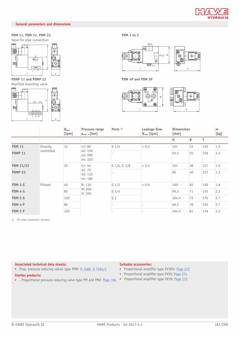
© HAWE Hydraulik SE HAWE Products - 04-2017-5.1 187/299
Associated technical data sheets:■ Prop. pressure reducing valves type PDM: D 7486, D 7584/1
Similar products:■ , Proportional pressure-reducing valve type PM and PMZ: Page 184
Suitable accessories:■ Proportional amplifier type EV1M3: Page 272■ Proportional amplifier type EV2S: Page 274■ Proportional amplifier type EV1D: Page 272
General parameters and dimensions
PDM 11, PDM 21, PDM 22 PDM 3 to 5Valve for pipe connection
PDMP 11 and PDMP 22 PDM 4P and PDM 5PManifold mounting valve
Qmax
[lpm]Pressure rangepmax A [bar]
Ports 1) Leakage ow Qleak [lpm]
Dimensions[mm]
m[kg]
H B T
PDM 11 G 1/4 101 33 150 1.5
PDMP 11
12 41: 80 42: 130 43: 200 44: 320
-
< 0.5
93,5 35 150 1.4
PDM 21/22 G 1/4, G 3/8 101 38 157 1.6
PDMP 22
Directly controlled
20 41: 45 42: 70 43: 110 44: 180
-
< 0.5
96 40 157 1.3
PDM 3 G 40 G 1/2 100 65 150 1.8
PDM 4 G 80 G 3/4 99.5 71 155 2.2
PDM 5 G 120 G 1
< 0.8
104.5 73 170 2.7
PDM 4 P 80 - - 99.5 78 150 2.7
PDM 5 P
Piloted
120
N: 130 M: 200 H: 350
- - 104.5 81 178 3.2
1) For pipe connection versions

Pressure valves
188/299 HAWE Products - 04-2017-5.1 © HAWE Hydraulik SE
2.3 Proportional pressure-reducing valve type KFB and FB
Proportional pressure-reducing valves are a type of pressure control valve. They manually
and continuously operate hydraulic actuators at a distance.
The proportional pressure-reducing valve type FB is available as a single valve for pipe
connection. Type KFB is a valve bank and combines several valves.
The proportional pressure-reducing valve type FB and KFB is primarily used for remote
control of the directional spool valve type PSL or PSV.
Features and benets:■ Sturdy design■ Precise control
Intended applications:■ For control oil supply in pilot circuits
Additional versions:■ With UNF thread
Nomen-clature:
Proportional pressure-reducing valveHydraulic joystick
Design: Single valve / Valve bank in pipe connection
pmax: 30 bar
Qmax: 2 l/min
Design and order coding example
KFB01 A /19 /F 1
Additional elements for actuation Without labelling - with hand lever1 - Without hand lever005 - with hand lever bent at an angle of 5°015 - With hand lever bent at an angle of 15°025 - With hand lever bent at an angle of 25°030 - With hand lever bent at an angle of 30°
Manual operation F - manual operation with return springFC - detent
Pressure range of prop. pressure-reducing valve Pressure ranges4; 5.5; 7; 9; 11; 14; 19; 30
Valve sections A - Front sectionM - Middle sectionE - End section
Basic type, size Type KFB (valve bank)Type FB (single valve)
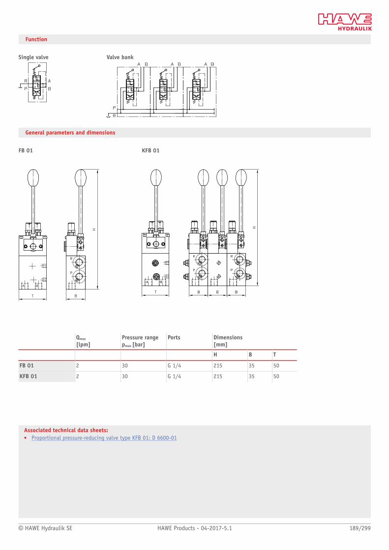
© HAWE Hydraulik SE HAWE Products - 04-2017-5.1 189/299
Associated technical data sheets:■ Proportional pressure-reducing valve type KFB 01: D 6600-01
Function
Single valve Valve bank
General parameters and dimensions
FB 01 KFB 01
Qmax
[lpm]Pressure rangepmax [bar]
Ports Dimensions[mm]
H B T
FB 01 2 30 G 1/4 215 35 50
KFB 01 2 30 G 1/4 215 35 50
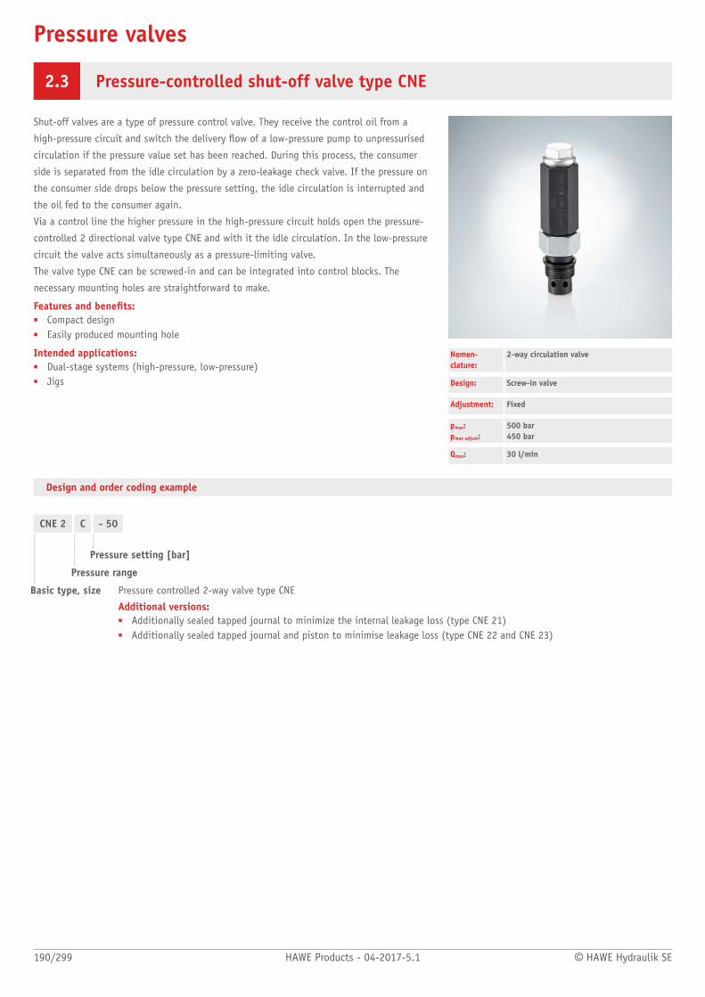
Pressure valves
190/299 HAWE Products - 04-2017-5.1 © HAWE Hydraulik SE
2.3 Pressure-controlled shut-off valve type CNE
Shut-off valves are a type of pressure control valve. They receive the control oil from a
high-pressure circuit and switch the delivery ow of a low-pressure pump to unpressurised
circulation if the pressure value set has been reached. During this process, the consumer
side is separated from the idle circulation by a zero-leakage check valve. If the pressure on
the consumer side drops below the pressure setting, the idle circulation is interrupted and
the oil fed to the consumer again.
Via a control line the higher pressure in the high-pressure circuit holds open the pressure-
controlled 2 directional valve type CNE and with it the idle circulation. In the low-pressure
circuit the valve acts simultaneously as a pressure-limiting valve.
The valve type CNE can be screwed-in and can be integrated into control blocks. The
necessary mounting holes are straightforward to make.
Features and benets:■ Compact design■ Easily produced mounting hole
Intended applications:■ Dual-stage systems (high-pressure, low-pressure)■ Jigs
Nomen-clature:
2-way circulation valve
Design: Screw-in valve
Adjustment: Fixed
pmax:pmax adjust:
500 bar450 bar
Qmax: 30 l/min
Design and order coding example
CNE 2 C - 50
Pressure setting [bar]
Pressure range
Basic type, size Pressure controlled 2-way valve type CNE
Additional versions:■ Additionally sealed tapped journal to minimize the internal leakage loss (type CNE 21)■ Additionally sealed tapped journal and piston to minimise leakage loss (type CNE 22 and CNE 23)

© HAWE Hydraulik SE HAWE Products - 04-2017-5.1 191/299
Associated technical data sheets:■ Pressure-controlled shut-off valve type CNE: D 7710 NE
Similar products:■ Two-stage valves type NE: Page 192■ Switch units type CR: Page 152■ Shut-off valves type LV, ALZ: Page 194■ Directional valves type AE: Page 168
Connection blocks:■ Connection block type A: Page 62
Function
General parameters and dimensions
Qmax
[lpm]Operating pressure pmax [bar] with
Dimensions [mm]
P Z H H1 SW SW1
CNE 2
CNE 21
CNE 23
30 E: 30D:45C:60 B:75 A:90 M:120 L:150
500 70 96 22 24
CNE 22 30 C: 320B: 450
500 120 147 30 27
Circuit example:
HK448/1-HH..-AN21F2
Idle circulation valve integrated in connection block type AN 21 F2 for compact hydraulic power packs type HK with two pump circuits
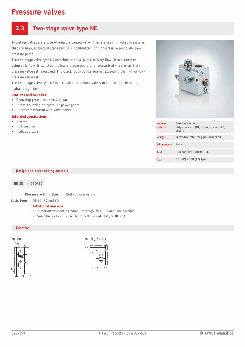
Pressure valves
192/299 HAWE Products - 04-2017-5.1 © HAWE Hydraulik SE
2.3 Two-stage valve type NE
Two-stage valves are a type of pressure control valve. They are used in hydraulic systems
that are supplied by dual stage pumps, a combination of high-pressure pump and low-
pressure pump.
The two-stage valve type NE combines the two pump delivery ows into a common
volumetric ow. It switches the low-pressure pump to unpressurised circulation if the
pressure value set is reached. It protects both pumps against exceeding the high or low-
pressure value set.
The two-stage valve type NE is used with directional valves to control double-acting
hydraulic cylinders.
Features and benets:■ Operating pressures up to 700 bar■ Direct mounting on hydraulic power packs■ Direct combination with valve banks
Intended applications:■ Presses■ Test benches■ Hydraulic tools
Nomen-clature:
Two stage valve (high pressure (HP) / low pressure (LP)stage)
Design: Individual valve for pipe connection
Adjustment: Fixed
pmax: 700 bar (HP) / 80 bar (LP)
Qmax: 25 (HP) / 180 (LP) lpm
Design and order coding example
NE 20 - 650/20
Pressure setting [bar] High- /low pressure
Basic type NE 20, 70 and 80
Additional versions:■ Direct attachment on pump units type MPN, RZ and FXU possible■ Valve banks type BV can be directly mounted (type NE 21)
Function
NE 20 NE 70, NE 80
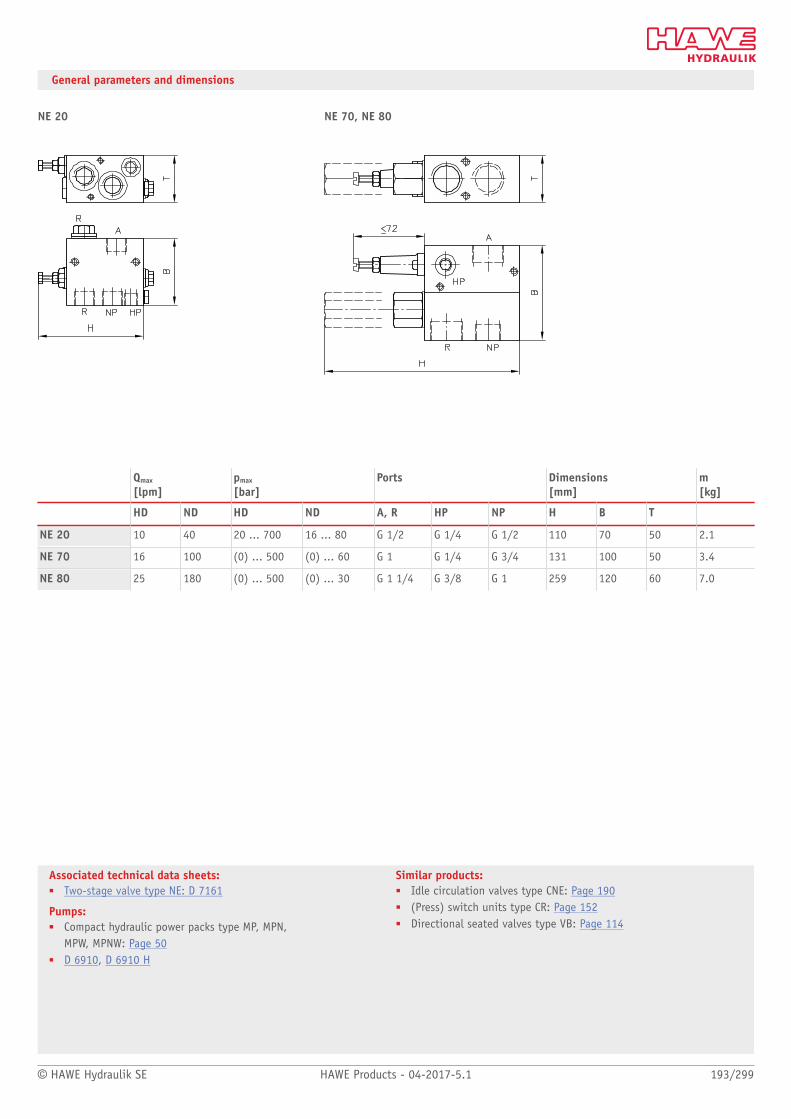
© HAWE Hydraulik SE HAWE Products - 04-2017-5.1 193/299
Associated technical data sheets:■ Two-stage valve type NE: D 7161
Pumps:■ Compact hydraulic power packs type MP, MPN,
MPW, MPNW: Page 50■ D 6910, D 6910 H
Similar products:■ Idle circulation valves type CNE: Page 190■ (Press) switch units type CR: Page 152■ Directional seated valves type VB: Page 114
General parameters and dimensions
NE 20 NE 70, NE 80
Qmax
[lpm]pmax
[bar]Ports Dimensions
[mm]m[kg]
HD ND HD ND A, R HP NP H B T
NE 20 10 40 20 ... 700 16 ... 80 G 1/2 G 1/4 G 1/2 110 70 50 2.1
NE 70 16 100 (0) ... 500 (0) ... 60 G 1 G 1/4 G 3/4 131 100 50 3.4
NE 80 25 180 (0) ... 500 (0) ... 30 G 1 1/4 G 3/8 G 1 259 120 60 7.0

Pressure valves
194/299 HAWE Products - 04-2017-5.1 © HAWE Hydraulik SE
2.3 Shut-off valve type LV and ALZ
Shut-off valves or accumulator charging valves are a type of pressure control valve. They
switch the delivery ow of a pump to unpressurised circulation if the pressure value set is
reached. During this process, the consumer side is separated from the idle circulation by a
zero-leakage check valve. If the pressure drops in the consumer side, the idle circulation is
interrupted and the oil fed to the consumer again.
The shut-off valve type LV and ALZ operates using automatically controlled (pulse indepen-
dent) step switching in the pilot valve.
Features and benets:■ Various means of adjustment■ Various additional functions
Intended applications:■ Test benches■ Accumulator systems■ Hydraulic tools
Nomen-clature:
Shut-off valve(idle circulation valve, directly controlled orpilot-controlled)
Design: Individual valve for pipe connectionIndividual valve Manifold mounting
Adjustment: Fixed manually adjustable
pmax: 350 bar
Qmax: 120 l/min
Design and order coding example
LV 10 PALZ 3 G
DCR
- 180 - 250
Pressure setting [bar]
Pressure range ■ Fixed (-)■ Manually adjustable (R)
Basic type, size, design Type LV, size 10, 20, 25
■ Pipe connection (-)■ Manifold mounting (P)■ Design with low switching hysteresis (type LV 25)
Type ALZ, size 3 to 5
■ Pipe connection (G)■ Manifold mounting (P)
Function
LV, ALZFor pipe connection: Manifold mounting valve:

© HAWE Hydraulik SE HAWE Products - 04-2017-5.1 195/299
Associated technical data sheets:■ Shut-off valve type LV: D 7529■ Shut-off valve type ALZ: D 6170 ALZ■ Pressure valve with check valve type AL, AE and AS: D 6170
Similar products:■ Release valves type AE: Page 168■ Connection blocks type AL: Page 62
General parameters and dimensions
LV .. ALZ .. G ..
1 Size 5: turned by 90°
ALZ .. P ..
Control Qmax
[lpm]Pressure range:pmax [bar]
Ports1) Dimensions [mm]
m[kg]
H B T
LV 10 12 F: 60 E: 140 D: 240 C: 350
G 1/4 155 45 32 0.9
LV 20, LV 25
Direct
25 F: 80 E: 140 D: 220 C: 350
G 3/8 205 50 32 1.2
ALZ 3 G 50 G 1/2 80 40 99 2.0
ALZ 4 G 80 G 3/4 94 40 109 2.4
ALZ 5 G 120 G 1 105 63 135 4.3
ALZ 4 P 80 G 3/4 60 40 119 2.1
ALZ 5 P
Piloted
120
F: 60 E: 140 D: 240 C: 350
G 1 80 40 133 4.3
1) For pipe connection versions only

Pressure valves
196/299 HAWE Products - 04-2017-5.1 © HAWE Hydraulik SE
2.3 Pressure-dependent shut-off valve type DSV and CDSV
Pressure-dependent shut-off valves are a type of pressure control valve. When a set pressure
value is reached and exceeded, they block the ow to consumer line B with zero leakage.
The valves will open again if the pressure on inow side A falls below the set value dened
by the spring tension.
The pressure-dependent shut-off valve type DSV and CDSV is used as a safeguard pressure
gauge, for example.
Features and benets:■ Various adjustment options
Intended applications:■ General hydraulic systems■ Test benches■ (Pressure gauge) protection valve
Nomen-clature:
Shut-off valve
Design: Single valve for pipe connectionIndividual valve for manifold mountingScrew-in valve
Adjustment: Tool adjustable (xed)Manually (adjustable)
pmax: 600 bar
Qmax: 60 l/min
Design and order coding example
CDSV 1 A - 1/4 - 400
Pressure setting [bar]
Design with connection block (-1/4)Cartridge valve (-)
Pressure range Fixed (-) or manually adjustable (R)
Basic type, size Type CDSV (cartridge valve), size 1
DSV 21-1 B - 200
Pressure setting [bar]
Pressure range Fixed (-) or manually adjustable (R)
Basic type, size Type DSV (pipe connection), type DSVP (manifold mounting), size 1, 2, 3

© HAWE Hydraulik SE HAWE Products - 04-2017-5.1 197/299
Associated technical data sheets:■ Pressure-controlled shut-off valve type DSV: D 3990■ Pressure-controlled shut-off valve type CDSV: D 7876
Function
CDSV 1, DSV 2 DSVP 2
DSVP
General parameters and dimensions
CDSV 1 DSV 2-2
1 Manually adjustable
DSVP 21-1
1 Fixed
Design Size Qmax
[lpm]pmax
[bar]Ports Hmax
[mm]SW= a/f
m[kg]
CDSV 1 Screw-in valve 1 10 C: 120 B: 350 A: 600
M 16 x 1.5 69 SW 22 0.13
1 20 D: 40 C: 100 B: 220 A: 600
G 1/4 185 SW 36 0.7
2 40 D: 20 C: 60 B: 120 A: 400
G 3/8 193 SW 36 0.9
DSV 21) Version for pipe connection
3 60 D: 20 C: 60 B: 120 A: 400
G 1/2 193 SW 46 1.1
DSVP 21) Manifold mounting valve 1 20 D: 40 C: 100 B: 220 A: 600
G 1/4 181 - 1.1
1) Manifold mounting valve only in size 1

Pressure valves
198/299 HAWE Products - 04-2017-5.1 © HAWE Hydraulik SE
2.3 Load-holding valve type LHK, LHDV and LHT
Load-holding valves are a type of pressure control valve. They prevent loads on cylinders
or motors dropping in an uncontrolled manner. For this purpose they are pre-loaded with a
pressure setting that is higher than the largest possible load. A hydraulic piston controls
the opening of the valve to achieve the required lowering velocity.
The load-holding valves type LHK and LHT are suitable for applications that are not
particularly prone to oscillations. The load-holding valve type LHDV has special damping
characteristics. It is used particularly in conjunction with proportional directional spool
valves, e.g. type PSL and PSV.
Shock valves and shuttle valves with or without restrictor check valves can be tted in the
load-holding valves type LHK, LHDV and LHT, e.g. to relieve hydraulic brakes with a delay.
Features and benets:■ Operating pressures up to 420 bar■ Various adjustment options■ Various configurations
Intended applications:■ Cranes■ Construction machinery■ Lifting devices
Nomen-clature:
Load holding valve (over center valve, for one sided or alternat-ing load direction) Single or twin valve
Design: Individual or twin valve for pipe connectionIndividual or twin manifold mounting valveScrew-in valveVersion for banjo bolt mounting
pmax: 450 bar
Qmax: 250 l/min
Design and order coding example
LHK44 G - 11 - 160
Pressure setting load-holding pressure [bar]
Design Various housing designs available
Dampening Without/with, or with restrictor check valve
Basic type, size Type LHK (valve only, without shock valve), size 2 to 4
Additional versions:■ Some available with release ratio 1 : 2 and 1 : 7■ Version available as assembly kit
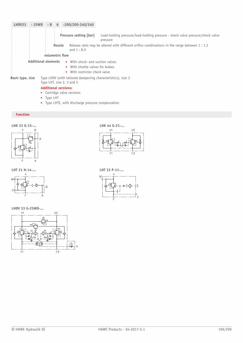
© HAWE Hydraulik SE HAWE Products - 04-2017-5.1 199/299
LHDV33 - 25WD - B 6 -200/200-240/240
Pressure setting [bar] Load-holding pressure/load-holding pressure - shock valve pressure/shock valvepressure
Nozzle Release ratio may be altered with different orice combinations in the range between 1 : 1.2 and 1 : 8.9
volumetric ow
Additional elements ■ With shock- and suction valves■ With shuttle valves for brakes■ With restrictor check valve
Basic type, size Type LHDV (with tailored dampening characteristics), size 3 Type LHT, size 2, 3 and 5
Additional versions:■ Cartridge valve versions■ Type LHT■ Type LHTE, with discharge pressure compensation
Function
LHK 33 G-15-... LHK 44 G-21-...
LHT 21 H-14-... LHT 33 P-11-...
LHDV 33 G-25WD-...

200/299 HAWE Products - 04-2017-5.1 © HAWE Hydraulik SE
General parameters and dimensions
LHK 44 G - 11 - 160 LHDV 33 - 25 WD - B 6 - 200/200 - 240/240Individual valve Twin valve
LHT 33 P - 15Individual valve
Design Qmax
[lpm]pmax
[bar]Pilot ratio Ports Dimensions
[mm]m[kg]
H/H1 B/B1 T/T1
Individual valve 97 32 32 0.5LHK 22
Twin valve2)
20 400 1 : 4.6 G 3/8
98 60 30 2.7
Individual valve 123 40 40 1.0LHK 33
Twin valve2)
60 360 1 : 4.4 G 1/2
125...291 80 40...60 2.7
Individual valve 170 45 45 1.6LHK 44
Twin valve2)
100 350 1 : 4.4 G 3/4
170 90 50 3.5
Individualvalve2)
170 50 40 1.8LHDV 33
Twin valve
80 420 1 : 8...1 : 1.21) G 1/2
170 88 70 4.7
Individual valve 132 40 24.8 1.2LHT 2
Twin valve
25 400 1 : 8, 1 : 4 G 1/4
132 50 24.8 0.8
LHT 3 Individualvalve2)
130 450 1 : 7...1 : 0.53 1) G 1/2 128 70 40 1.6
LHT 5 Individualvalve2)
250 450 1 : 6...1 : 0.791) G 1 113 50 50 1.0
1) Release ratio can be altered simply by changing the orice2) Note: Design may be significantly different to the illustrated version!

© HAWE Hydraulik SE HAWE Products - 04-2017-5.1 201/299
Associated technical data sheets:■ Load-holding valve type LHK: D 7100■ Load-holding valve type LHDV: D 7770■ Load-holding valve type LHT: D 7918
Suitable proportional directional spool valve:■ Proportional directional valves type EDL: Page 90■ Proportional directional valves type PSL, PSV: Page 90■ Proportional directional valves type PSLF, PSVF: Page 96
Circuit example:
LHDV 33-25-D6-180/180-200/200
LHDV 33 P-15-D6-280/300
LHDV 33 P-15-D6-280/300
LHK 33 G-21-... in accordance with D 7100

Valves
202/299 HAWE Products - 04-2017-5.1 © HAWE Hydraulik SE
2.4 Flow valves
Flow control valve type SF, SD and SK 206
Flow control valve (lowering brake valve) type SB, SQ, SJ and DSJ 210
Proportional ow control valve type SE and SEH 212
Flow divider type TQ 216
Restrictors and restrictor check valve type EB, BE, BC 218
Throttle valve type Q, QR, QV and FG 220
Throttle valve type ED, restrictor check valve type RD and RDF 222
Throttle valve and restrictor check valve type CQ, CQR and CQV 224
Throttle valve and shut-off valve type AV, AVT and CAV 226
Flow control valves with electro-proportional
actuation type SE and SEH
Throttles valves type Q, QR, QV and FG

© HAWE Hydraulik SE HAWE Products - 04-2017-5.1 203/299
Flow control valves
Type Design / adjustability pmax
(bar)Qmax
(lpm)
SF, SD, SK 2-way and 3-way ow control valve■ Single valve for pipe connection■ Manifold mounting valve
– Mechanical
SD - 3: 320SD - 4: 320SD - 5: 320
SF - 3: 320SF - 4: 320SF - 5: 320
SK - 3: 320SK - 4: 320SK - 5: 320
SD - 3: 60SD - 4: 90SD - 5: 130
SF - 3: 60SF - 4: 90SF - 5: 130
SK - 3: 60SK - 4: 90SK - 5: 130
SB, SQ, SJ, DSJ 2-way metering valve, drop-rate braking valve■ Screw-in valve■ Combination with housing for pipe connection
– Tool adjustable, xed
SB - 0: 315SB - 1: 315SB - 2: 315SB - 3: 315SB - 4: 315SB - 5: 315
SQ - 0: 315SQ - 1: 315SQ - 2: 315SQ - 3: 315
SJ - 0: 315
DSJ - 1: 315
SB - 0: 15SB - 1: 35SB - 2: 67SB - 3: 150SB - 4: 250SB - 5: 400
SQ - 0: 15SQ - 1: 25SQ - 2: 67SQ - 3: 150
SJ - 0: 15
DSJ - 1: 25
SE, SEH 2-way and 3-way ow control valve■ Single valve for pipe connection■ Manifold mounting valve
– Electro-proportional
SE - 3: 320SE - 4: 320
SEH - 2: 320SEH - 3: 320SEH - 4: 320SEH - 5: 320
SE - 3: 50SE - 4: 90
SEH - 2: 30SEH - 3: 50SEH - 4: 90SEH - 5: 120
Flow dividers
Type Design / adjustability pmax
(bar)Qmax
(lpm)
TQ Flow dividers■ Single valve for pipe connection■ Manifold mounting valve
– Non-adjustable
3: 35043: 35054: 350
3: 7043: 12054: 200

204/299 HAWE Products - 04-2017-5.1 © HAWE Hydraulik SE
Restrictors, restrictor check valves
Type Design / features pmax
(bar)Qmax
(lpm)
EB, BE, BC Restrictor, restrictor check valve■ Plug-in valve■ Screw-in valve■ Combination with housing for pipe connection
EB - 0: 500EB - 1: 500EB - 2: 500EB - 3: 500EB - 4: 500
BE - 0: 500BE - 1: 500BE - 2: 500BE - 3: 500BE - 4: 500
BC - 1: 700BC - 2: 700BC - 3: 500
EB - 0: 6EB - 1: 12EB - 2: 40EB - 3: 100EB - 4: 120
BE - 0: 12BE - 1: 25BE - 2: 40BE - 3: 80BE - 4: 120
BC - 1: 20BC - 2: 35BC - 3: 60

© HAWE Hydraulik SE HAWE Products - 04-2017-5.1 205/299
Throttle valves and throttle shut-off valves
Type Design / adjustability pmax
(bar)Qmax
(lpm)
Q, QR, QV, FG Throttle valve, restrictor check valve■ Screw-in valve■ Single valve for pipe connection■ Angle valve■ Banjo bolt■ Swivel tting
– Tool adjustable
Q, QR - 20: 400Q, QR - 30: 400Q, QR - 40: 400Q, QR - 50: 400Q, QR - 60: 315
QV - 20: 400QV - 30: 400QV - 40: 400QV - 50: 400QV - 60: 315
FG: 320
Q, QR - 20: 12Q, QR - 30: 20Q, QR - 40: 40Q, QR - 50: 60Q, QR - 60: 80
QV - 20: 8QV - 30: 12QV - 40: 20QV - 50: 30QV - 60: 50
FG: 0.8
ED, RD, RDF Throttle valve, restrictor check valve■ Single valve for pipe connection
– Tool adjustable, xed– Manual, adjustable
ED, RD - 11: 500ED, RD - 21: 500ED, RD - 31: 500ED, RD - 41: 500ED, RD - 51: 500
RDF - 11: 500RDF - 21: 500RDF - 31: 500RDF - 41: 500RDF - 51: 500
ED, RD - 11: 15ED, RD - 21: 35ED, RD - 31: 60ED, RD - 41: 100ED, RD - 51: 150
RDF - 11: 15RDF - 21: 35RDF - 31: 60RDF - 41: 100RDF - 51: 150
CQ, CQR, CQV Throttle valve, restrictor check valve■ Screw-in valve
– Tool adjustable
CQ - 2: 700
CQR - 2: 700
CQV - 2: 700
CQ - 2: 50
CQR - 2: 50
CQV - 2: 50
AV, AVT, CAV Throttle and shut-off valve■ Single valve for pipe connection■ Screw-in valve
– Tool adjustable, xed– Manual, adjustable
AV - 2: 500AV - 3: 400
CAV - 1: 500CAV - 2: 500
AVT - 6: 630AVT - 8: 630AVT - 10: 630AVT - 12: 630
AVM - 8: 500AVM - 8L: 315
AV - 2: 40AV - 3: 100
CAV - 1: 15CAV - 2: 25

Flow valves
206/299 HAWE Products - 04-2017-5.1 © HAWE Hydraulik SE
2.4 Flow control valve type SF, SD and SK
Flow control valves are a type of ow valve. They generate a set constant ow rate, largely
independently of the load.
The ow control valve type SD, SF and SK can be freely adjusted with different mechani-
cal actuations. The ow control valve type SD, SF and SK is available as a 2-way and 3-way
ow control valve. For type SD, the adjustment is made using the adjusting knob; for type
SF using the adjusting screw; and for type SK using the roller actuation. The ow control
valve type SD, SF and SK is available as a single valve for pipe connection or as a manifold
mounting valve.
Pressure-limiting valves and randomly switchable idle circulation valves are additional
options. The ow control valve type SD, SF and SK controls the operating speed of the
hydraulic consumers.
Features and benets:■ Various actuation types■ Can also be combined with bypass check valves■ Precise setting
Intended applications:■ Construction machinery■ Machine tools■ General hydraulic systems
Nomen-clature:
2-way ow control valve3-way ow control valve
Design: Individual valves for pipe mounting Manifold mounting
Adjustment: Mechanical
■ Adjusting knob■ Roller actuation■ Setting screw
pmax: 315 bar
Qmax: 130 l/min
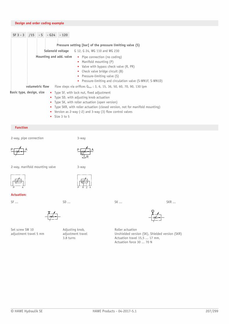
© HAWE Hydraulik SE HAWE Products - 04-2017-5.1 207/299
Design and order coding example
SF 3 - 3 /15 - S - G24 - 120
Pressure setting [bar] of the pressure limiting valve (S)
Solenoid voltage G 12, G 24, WG 110 and WG 230
Mounting and add. valve ■ Pipe connection (no coding)■ Manifold mounting (P)■ Valve with bypass check valve (R, PR)■ Check valve bridge circuit (B)■ Pressure-limiting valve (S)■ Pressure-limiting and circulation valve (S-WN1F, S-WN1D)
volumetric ow Flow steps via orices Qmax : 3, 6, 15, 36, 50, 60, 70, 90, 130 lpm
Basic type, design, size ■ Type SF, with lock nut, xed adjustment■ Type SD, with adjusting knob actuation■ Type SK, with roller actuation (open version)■ Type SKR, with roller actuation (closed version, not for manifold mounting)■ Version as 2-way (-2) and 3-way (3) ow control valves■ Size 3 to 5
Function
2-way, pipe connection 3-way
2-way, manifold mounting valve 3-way
Actuation:
SF ... SD ... SK ... SKR ...
Set screw SW 10adjustment travel 5 mm
Adjusting knob,adjustment travel 3.8 turns
Roller actuation Unshielded version (SK), Shielded version (SKR)Actuation travel 15,5 ... 17 mm, Actuation force 30 ... 70 N

208/299 HAWE Products - 04-2017-5.1 © HAWE Hydraulik SE
General parameters and dimensions
Version for pipe connection Manifold mounting valve
1 Idle circulation valve
2 Pressure-limiting valve
3 Setting screw
1 Adjusting knob
Qmax [lpm]1) Ports2) Dimensions [mm] m [kg]3)
2-way 3-way H H1 L L1 B B1
S. 2-3 50 40 80 93 50 60 1,4 ... 2,1
S. 3-3
0,3 ... 60 G 1/2
50 40 80 93 50 60 1,4 ... 2,1
S. 2-4 60 50 85 100 60 70 2
S. 3-4
0.3 ... 90 G 3/4
60 50 85 100 60 70 2,0 ... 2,6
S. 2-5 70 50 100 106 70 80 3,1
S. 3-5
1,0 ... 130 G 1
70 50 100 106 70 80 2,8 ... 3,7
1) Different Qmax available, see Design and order coding example: "Orice steps"2) For pipe connection versions3) Depending on actuations
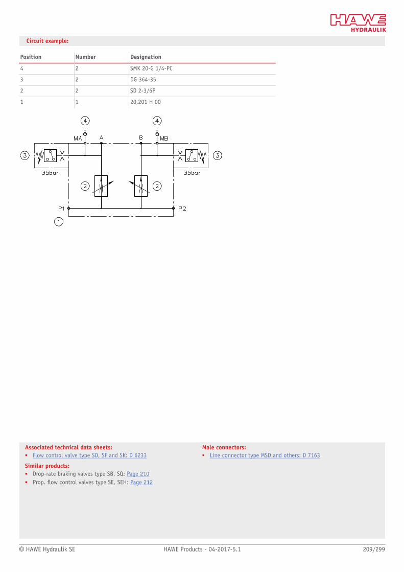
© HAWE Hydraulik SE HAWE Products - 04-2017-5.1 209/299
Associated technical data sheets:■ Flow control valve type SD, SF and SK: D 6233
Similar products:■ Drop-rate braking valves type SB, SQ: Page 210■ Prop. ow control valves type SE, SEH: Page 212
Male connectors:■ Line connector type MSD and others: D 7163
Circuit example:
Position Number Designation
4 2 SMK 20-G 1/4-PC
3 2 DG 364-35
2 2 SD 2-3/6P
1 1 20,201 H 00

Flow valves
210/299 HAWE Products - 04-2017-5.1 © HAWE Hydraulik SE
2.4 Flow control valve (lowering brake valve) type SB, SQ, SJ and DSJ
Flow control valves are a type of ow valve. They generate a set constant ow rate, largely
independently of the load.
The ow control valve type SB and SQ is available as a screw-in cartridge, a housing version
with pipe connection or as a banjo screw version. Type SB has a slightly inclined character-
istic curve for oscillation damping. Type SQ is largely independent of the load.
The freely movable sliding metering orice enables greater ow in the opposite ow
direction. No bypass check valve is therefore required. The ow control valve type SB and
SQ is used to control the lowering speed of single-acting consumers.
Features and benets:■ Oscillation damping and load-independent■ Compact screw-in valve
Intended applications:■ General hydraulic systems■ Industrial trucks■ Lifting equipment
Nomen-clature:
2-way ow control valve (drop rate braking valve)
Design: Screw-in type with housing for in-line installation
Adjustment: Fixed (pre-set) Tool adjustable from outside
pmax: 315 bar
Qmax: 400 lpm
Design and order coding example
SB 2 1 C - 30
Response ow [l/min] Desired factory set response ow within the respective range
Design Adjustable or non adjustable version
■ Screw-in version (C)■ Version with housing for pipe mounting (E, F, G)
Additional versions■ With metric of UNF-thread■ With thread adaptor■ As banjo bolt and/or with swiveling screw tting
Adjustment range Adjustable response ow
Basic type, size Type SB, SQ and SJ, sizeType DSJ, ow control function in both directions for double-acting consumers

© HAWE Hydraulik SE HAWE Products - 04-2017-5.1 211/299
Associated technical data sheets:■ Flow control valve (lowering brake valve) type SB and SQ: D 6920■ Flow control valve type SJ: D 7395■ Flow control valve type CSJ: D 7736■ Flow control valve type DSJ: D 7825
Function
SB, SQ SJ DSJ
General parameters and dimensions
Screw-in valve ...C With housing...GSB, SQ SJ
Coding for adjustment range of the set response ow from ... to ... [lpm] below
Ports Dimensions[mm]
m[g]
1 3 5 7 9 90 G (Series) L L1 max SW= a/f
SB 0 39 78 19 13
SJ 01)
1...1.6 1.6...2.5 2.5...4 4...6.3 6.3...10 10...15 G 1/4 (A)
24 - - 35
SB 1
SQ 1
2.5...4 4...6.3 6.3...10 10...16 16...25 25...35 G 3/8 (A) 43 82 22 23
SB 2
SQ 2
16...21 21...28 28...37 37...50 50...672) - G 1/2 (A) 49 96 27 40
SB 3
SQ 3
37...50 50...67 67...90 90...120 120...1502) - G 3/4 (A) 61 106 32 80
SB 4 80...100 100...125 125...160 160...200 200...250 - G 1 (A) 78 145 41 150
SB 5 170...200 200...236 236...280 280...335 335...400 - G 1 1/4 (A) 94 160 50 300
DSJ 1 1.0...21.0 G 3/8 (A) 39 78 19 30
1) Type SJ 0 without coding: adjust. range 0.25 ... 1.2 l/min2) Not for type SQ..
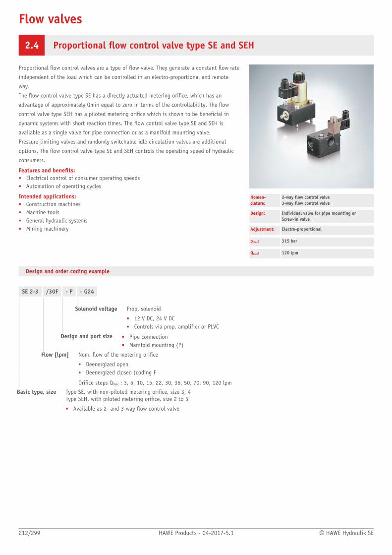
Flow valves
212/299 HAWE Products - 04-2017-5.1 © HAWE Hydraulik SE
2.4 Proportional ow control valve type SE and SEH
Proportional ow control valves are a type of ow valve. They generate a constant ow rate
independent of the load which can be controlled in an electro-proportional and remote
way.
The ow control valve type SE has a directly actuated metering orice, which has an
advantage of approximately Qmin equal to zero in terms of the controllability. The ow
control valve type SEH has a piloted metering orice which is shown to be benecial in
dynamic systems with short reaction times. The ow control valve type SE and SEH is
available as a single valve for pipe connection or as a manifold mounting valve.
Pressure-limiting valves and randomly switchable idle circulation valves are additional
options. The ow control valve type SE and SEH controls the operating speed of hydraulic
consumers.
Features and benets:■ Electrical control of consumer operating speeds■ Automation of operating cycles
Intended applications:■ Construction machines■ Machine tools■ General hydraulic systems■ Mining machinery
Nomen-clature:
2-way ow control valve 3-way ow control valve
Design: Individual valve for pipe mounting or Screw-in valve
Adjustment: Electro-proportional
pmax: 315 bar
Qmax: 120 lpm
Design and order coding example
SE 2-3 /30F - P - G24
Solenoid voltage Prop. solenoid
■ 12 V DC, 24 V DC■ Controls via prop. amplifier or PLVC
Design and port size ■ Pipe connection■ Manifold mounting (P)
Flow [lpm] Nom. ow of the metering orice
■ Deenergized open■ Deenergized closed (coding F
Orice steps Qmax : 3, 6, 10, 15, 22, 30, 36, 50, 70, 90, 120 lpm
Basic type, size Type SE, with non-piloted metering orice, size 3, 4Type SEH, with piloted metering orice, size 2 to 5
■ Available as 2- and 3-way ow control valve
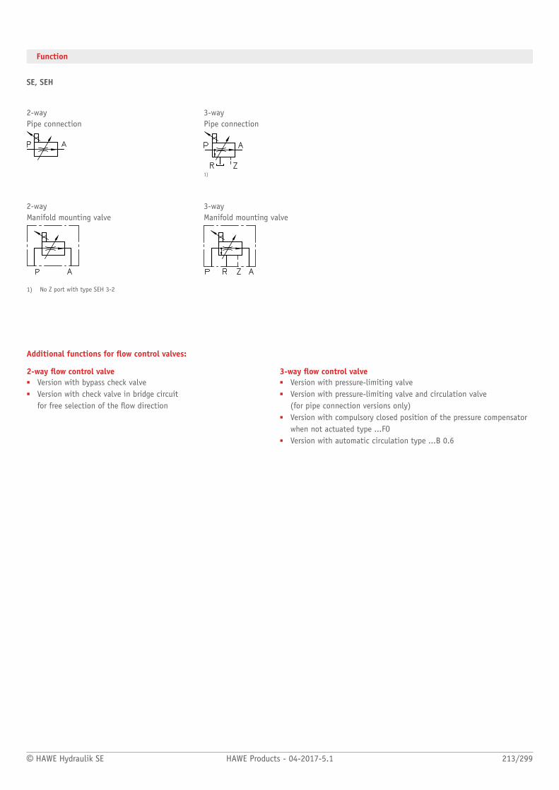
© HAWE Hydraulik SE HAWE Products - 04-2017-5.1 213/299
Function
SE, SEH
2-way 3-wayPipe connection Pipe connection
1)
2-way 3-wayManifold mounting valve Manifold mounting valve
1) No Z port with type SEH 3-2
Additional functions for ow control valves:
2-way ow control valve■ Version with bypass check valve■ Version with check valve in bridge circuit
for free selection of the ow direction
3-way ow control valve■ Version with pressure-limiting valve■ Version with pressure-limiting valve and circulation valve
(for pipe connection versions only)■ Version with compulsory closed position of the pressure compensator
when not actuated type ...FO■ Version with automatic circulation type ...B 0.6

214/299 HAWE Products - 04-2017-5.1 © HAWE Hydraulik SE
General parameters and dimensions
SEH SEVersion for pipe connection Manifold mounting valve
Basic type and size Qmax
[lpm]1)pmax
[bar]Ports2) Dimensions
[mm]mmax
[kg]
2-way 3-way H B T
SE 2-3 SE 3-3 0,3 ... 50 315 G 1/2 110 ... 120 80 ... 91 50 ... 60 2,2
SE 2-4 SE 3-4Directly actuated
0.6 ... 90 315 G 3/4 120 ... 130 85 ...100 60 ... 70 2,2
SEH 2-2 SEH 3-2 0.1 ... 36 315 G 3/8 115 55 ... 70 39 1,6 ... 3,3
SEH 2-33) SEH 3-3 0,3 ... 50 315 G 1/2 92,5 80 ... 93 50 ... 60 1,6 ... 3,3
- SEH 3-4 0,6 ... 90 315 G 3/4 102,5 95 ... 100 60 ... 70 1,6 ... 3,3
- SEH 3-5
Hydraulicallypiloted
1,0 ... 120 315 G 1 112,5 100 70 1,6 ... 3,3
1) Different Qmax available, see Design and order coding example: "Orice steps"2) For pipe connection versions3) For manifold mounting versions only
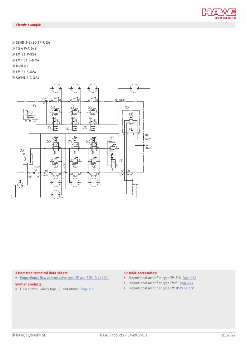
© HAWE Hydraulik SE HAWE Products - 04-2017-5.1 215/299
Associated technical data sheets:■ Proportional ow control valve type SE and SEH: D 7557/1
Similar products:■ Flow control valves type SD and others: Page 206
Suitable accessories:■ Proportional amplifier type EV1M3: Page 272■ Proportional amplifier type EV2S: Page 274■ Proportional amplifier type EV1D: Page 272
Circuit example
; SEHD 3-3/30 FP-X 24
< TQ 4 P-A 5/2
= EM 31 V-X24
> EMP 31 S-X 24
? MVH 6 C
@ EM 31 S-X24
A SWPN 2-G-X24

Flow valves
216/299 HAWE Products - 04-2017-5.1 © HAWE Hydraulik SE
2.4 Flow divider type TQ
Flow dividers are a type of metering valve. They divide or add together a total ow rate
either evenly or using a xed ratio. The consumer pressures have no effect.
The ow divider type TQ is, due to its simple design, an economical solution for simple
dividing tasks, e.g. if two hydraulic consumers with varying loads supplied from one pump
are to be moved simultaneously without interaction.
Intended applications include mobile hydraulics and industrial hydraulics.
Features and benets:■ Excellent dividing accuracy
Intended applications:■ Steering systems■ Synchronous cylinders
Nomen-clature:
Flow dividers
Design: Individual valve for pipe mounting Manifold mounting
Adjustment: Non-adjustable
pmax: 350 bar
Qmax: 200 lpm (nom. total ow)
Design and order coding example
TQ 32 - A- 2,3- 3
Coding Flow indicator
Design ■ A – equal division ratio■ R - with bypass check valve
Basic type, size ■ Pipe connection (no coding)■ Manifold mounting (P)
Type TQ, size 2 to 5
Function
TQ TQ.PPipe connection Manifold mounting valve
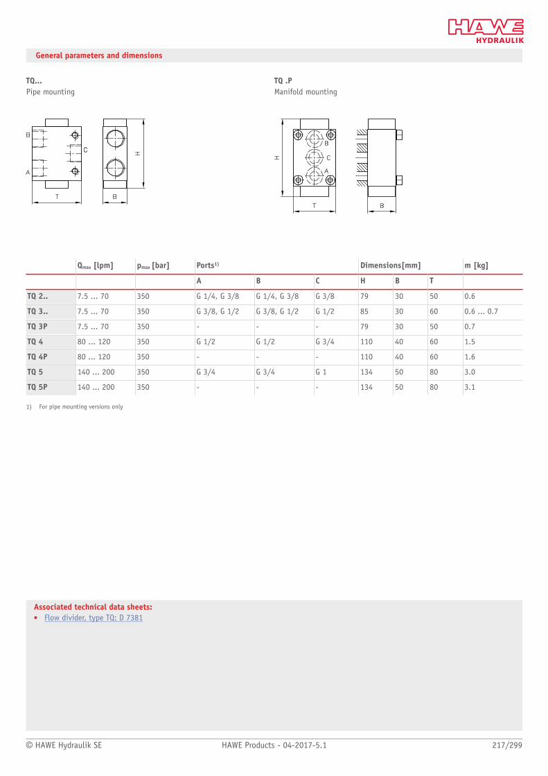
© HAWE Hydraulik SE HAWE Products - 04-2017-5.1 217/299
Associated technical data sheets:■ Flow divider, type TQ: D 7381
General parameters and dimensions
TQ... TQ .PPipe mounting Manifold mounting
Qmax [lpm] pmax [bar] Ports1) Dimensions[mm] m [kg]
A B C H B T
TQ 2.. 7.5 ... 70 350 G 1/4, G 3/8 G 1/4, G 3/8 G 3/8 79 30 50 0.6
TQ 3.. 7.5 ... 70 350 G 3/8, G 1/2 G 3/8, G 1/2 G 1/2 85 30 60 0.6 ... 0.7
TQ 3P 7.5 ... 70 350 - - - 79 30 50 0.7
TQ 4 80 ... 120 350 G 1/2 G 1/2 G 3/4 110 40 60 1.5
TQ 4P 80 ... 120 350 - - - 110 40 60 1.6
TQ 5 140 ... 200 350 G 3/4 G 3/4 G 1 134 50 80 3.0
TQ 5P 140 ... 200 350 - - - 134 50 80 3.1
1) For pipe mounting versions only

Flow valves
218/299 HAWE Products - 04-2017-5.1 © HAWE Hydraulik SE
2.4 Restrictors and restrictor check valve type EB, BE, BC
Restrictors are a type of ow valve. They are used as a local ow resistance that suddenly
reduces the line cross-section. The reduction in the cross-section is very short. As a result,
the ow rate is only dependent on the pressure difference and not on the viscosity.
The restrictor check valve type BE and BC combines the function of a ow valve with a
check valve. The valve is available as a perforated restrictor or as a slotted restrictor. It
limits the ow during the switching of directional valves. E.g. it prevents excessively quick
accumulator emptying.
The orice insert type EB is primarily used in valves for manifold mounting. As such an
additional intermediate plate is not necessary.
Features and benets:■ Max. 700 bar■ Simple design and installation
Intended applications:■ General hydraulics■ Winch controls■ Hydraulic pilot systems
Nomen-clature:
RestrictorRestrictor check valve
Design: Plug-in valveInsert valvesCombination with housing for pipeconnection
pmax: 700 bar
Qmax: 120 l/min
Design and order coding example
BC1 - 0,8 G
Design with housing For pipe connection, type BC, BE (E; F, G)
Orice Hole or slot type orice, diameter in mm
Basic type, size Type BC, size 1 to 3Type BE, size 1 to 4Type EB, size 0 to 4, Orice insert
Additional versions■ Type BC and BE with metric thread
Function
BC BE EBScrew-in valve Orice insert
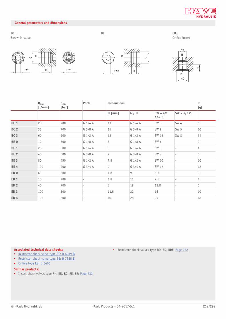
© HAWE Hydraulik SE HAWE Products - 04-2017-5.1 219/299
Associated technical data sheets:■ Restrictor check valve type BC: D 6969 B■ Restrictor check valve type BE: D 7555 B■ Orice type EB: D 6465
Similar products:■ Insert check valves type RK, RB, RC, RE, ER: Page 232
■ Restrictor check valves type RD, ED, RDF: Page 222
General parameters and dimensions
BC.. BE .. EB..Screw-in valve Orice insert
Qmax
[l/min]pmax
[bar]Ports Dimensions m
[g]
H [mm] G / D SW = a/f1/Æd
SW = a/f 2
BC 1 20 700 G 1/4 A 13 G 1/4 A SW 8 SW 4 6
BC 2 35 700 G 3/8 A 15 G 3/8 A SW 9 SW 5 10
BC 3 60 500 G 1/2 A 18 G 1/2 A SW 12 SW 8 24
BE 0 12 500 G 1/8 A 5 G 1/8 A SW 4 - 2
BE 1 25 500 G 1/4 A 6 G 1/4 A SW 5 - 4
BE 2 40 500 G 3/8 A 7 G 3/8 A SW 8 - 6
BE 3 80 450 G 1/2 A 7.5 G 1/2 A SW 10 - 10
BE 4 120 400 G 3/4 A 9 G 3/4 A SW 12 - 18
EB 0 6 500 - 1.8 9 5.6 - 2
EB 1 10 700 - 1.8 11 7.5 - 4
EB 2 40 700 - 9 18 12.8 - 6
EB 3 100 500 - 11.5 22 16 - 10
EB 4 120 500 - 10 28 25 - 18
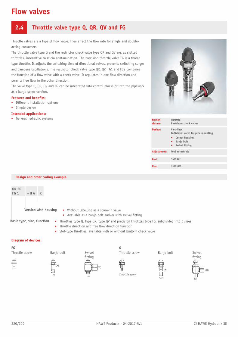
Flow valves
220/299 HAWE Products - 04-2017-5.1 © HAWE Hydraulik SE
2.4 Throttle valve type Q, QR, QV and FG
Throttle valves are a type of ow valve. They affect the ow rate for single and double-
acting consumers.
The throttle valve type Q and the restrictor check valve type QR and QV are, as slotted
throttles, insensitive to micro contamination. The precision throttle valve FG is a thread
type throttle. It adjusts the switching time of directional valves, prevents switching surges
and dampens oscillations. The restrictor check valve type QR, QV, FG1 and FG2 combines
the function of a ow valve with a check valve. It regulates in one ow direction and
permits free ow in the other direction.
The valve type Q, QR, QV and FG can be integrated into control blocks or into the pipework
as a banjo screw version.
Features and benets:■ Different installation options■ Simple design
Intended applications:■ General hydraulic systems Nomen-
clature:Throttle Restrictor check valves
Design: Cartridge Individual valve for pipe mounting
■ Corner housing■ Banjo bolt■ Swivel tting
Adjustment: Tool adjustable
pmax: 400 bar
Qmax: 120 lpm
Design and order coding example
QR 20FG 1 - H 6 K
Version with housing ■ Without labelling as a screw-in valve■ Available as a banjo bolt and/or with swivel tting
Basic type, size, function ■ Throttles type Q, type QR, type QV and precision throttles type FG, subdivided into 5 sizes■ Throttle direction and free ow direction function■ Slot-type throttles, available with or without built-in check valve
Diagram of devices:
FG QThrottle screw Banjo bolt Swivel
ttingThrottle screw Banjo bolt Swivel
tting
Throttle screw
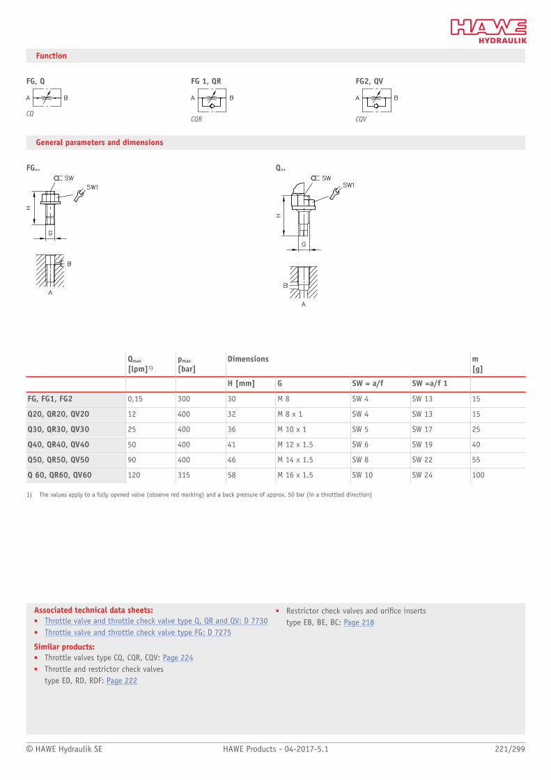
© HAWE Hydraulik SE HAWE Products - 04-2017-5.1 221/299
Associated technical data sheets:■ Throttle valve and throttle check valve type Q, QR and QV: D 7730■ Throttle valve and throttle check valve type FG: D 7275
Similar products:■ Throttle valves type CQ, CQR, CQV: Page 224■ Throttle and restrictor check valves
type ED, RD, RDF: Page 222
■ Restrictor check valves and orice inserts type EB, BE, BC: Page 218
Function
FG, Q FG 1, QR FG2, QV
CQCQR CQV
General parameters and dimensions
FG.. Q..
Qmax
[lpm]1)pmax
[bar]Dimensions m
[g]
H [mm] G SW = a/f SW =a/f 1
FG, FG1, FG2 0,15 300 30 M 8 SW 4 SW 13 15
Q20, QR20, QV20 12 400 32 M 8 x 1 SW 4 SW 13 15
Q30, QR30, QV30 25 400 36 M 10 x 1 SW 5 SW 17 25
Q40, QR40, QV40 50 400 41 M 12 x 1.5 SW 6 SW 19 40
Q50, QR50, QV50 90 400 46 M 14 x 1.5 SW 8 SW 22 55
Q 60, QR60, QV60 120 315 58 M 16 x 1.5 SW 10 SW 24 100
1) The values apply to a fully opened valve (observe red marking) and a back pressure of approx. 50 bar (in a throttled direction)

Flow valves
222/299 HAWE Products - 04-2017-5.1 © HAWE Hydraulik SE
2.4 Throttle valve type ED, restrictor check valve type RD and RDF
Throttle valves are a type of ow valve. They affect the ow rate for single and double-
acting consumers.
The restrictor check valve type RD and RDF combines the function of a ow valve with a
check valve. It regulates in one ow direction and permits free ow in the other direction.
Types ED and RD are adjustable.
The valve type ED, RD and RDF can be integrated directly in the line.
Features and benets:■ Sensitively adjustable■ Wear-resistant
Intended applications:■ General hydraulic systems
Nomen-clature:
Throttle Restrictor check valves
Design: Individual valve for pipe mounting Screw-in valve
Adjustment: Manually adjustable (handle, adjustingknob) Fixed
pmax: 500 bar
Qmax: 130 lpm
Design and order coding example
RD 11RDF 21 /1,0
- K
Adjustability ■ Type ED and RD only■ Without labelling = manually (wing bolt/lock nut)■ K = tool adjustable (setting spindle/lock nut)
Fixed throttles Diameter in mm, type RDF■ 0.4 - 0.6 (in increments of 0.1)■ 0.8 - 2.0 (in increments of 0.2)■ 2.5 - 5.5 (in increments of 0.5)
Basic type, size ■ Type ED, type RD, type RDF, size 1 to 5■ Slot-type throttles, available with or without built-in check valve
Function
ED RD RDF

© HAWE Hydraulik SE HAWE Products - 04-2017-5.1 223/299
Associated technical data sheets:■ Throttle and restrictor check valves
type ED, RD, RDF: D 7540, D 2570
Similar products:■ Throttle valves type Q, QR, QV, FG: Page 220■ Throttle valves type CQ, CQR, CQV: Page 224■ Restrictor check valves type EB, BE, BC: Page 218
General parameters and dimensions
ED.. and RD.. RDF..
1 Tool adjustable
1) Qmax
[lpm]2)pmax
[bar]Ports Dimensions
[mm]m[g]
H B SW = a/f
ED 11.. 23.5
RD 11.. 23.5
RDF 11/..
12 500 G 1/4
-
52 SW 24 180
ED 21.. 24
RD 21.. 24
RDF 21/..
30 500 G 3/8
-
52 SW 27 215
ED 31.. 32.5
RD 31.. 32.5
RDF 31/..
60 500 G 1/2
-
62 SW 32 340
ED 41.. 41
RD 41.. 41
RDF 41/..
80 500 G 3/4
-
72 SW 41 655
ED 51.. 46.5
RD 51.. 46.5
RDF 51/..
130 500 G 1
-
82 SW 46 835
1) The throttle diameter with type RDF canbe only altered by replacing the orice. Depending on size, diameters between 0.6 and 4 mm are available.2) These gures correspond to completely opened throttle and represent a back pressure of approx. 50 bar (throttled direction of ow)

Flow valves
224/299 HAWE Products - 04-2017-5.1 © HAWE Hydraulik SE
2.4 Throttle valve and restrictor check valve type CQ, CQR and CQV
Throttle valves are a type of ow valve. They affect the ow rate for single and double-
acting consumers.
The throttle valve type CQ and the restrictor check valve type CQR and CQV are, as slotted
throttles, insensitive to micro contamination. The restrictor check valve type CQR and CQV
combines the function of a ow valve with a check valve. It regulates in one ow direction
and permits free ow in the other direction. The double spindle sealing enables leakage-
free adjustment, even under pressure.
The valve type CQ, CQR and CQV can be screwed-in and can be integrated into control
blocks. The necessary mounting holes are straightforward to make.
Features and benets:■ Leak-free adjustment under pressure■ Operating pressure up to 700 bar
Intended applications:■ Speed regulation in hydraulic lifting devices
Nomen-clature:
Throttle Restrictor check valves
Design: Screw-in valve
Adjustment: Tool adjustable Manually
pmax: 700 bar
Qmax: 50 l/min
Design and order coding example
CQV 2 - D - 1/4
Single connection blocks ■ For pipe connection (1/4, 3/8)■ Manifold mounting (in combination with type CQ and CQV only)
Adjustability in operation ■ Without labelling = Fixed■ D = Turn knob (with lock nut)■ D3 = Turn knob, diameter 35 mm (without lock nut)
Basic type, size Type CQ, type CQR, type CQV, size 2Slot-type throttles, available with or without built-in check valve
■ Version with precision control range (size 22)■ Version with strong precision control range (size 23; only with turn knob D3)■ Version with pressure compensator (ow control function)

© HAWE Hydraulik SE HAWE Products - 04-2017-5.1 225/299
Associated technical data sheets:■ Throttle valve and throttle check valve type CQ, CQR and CQV:
D 7713
Similar products:■ Throttle and restrictor check valves
type ED, RD, RDF: Page 222■ Throttle valves type Q, QR, QV, FG: Page 220
Function
CQ 2, CQ 22, CQ 23 CQR 2, CQR 22, CQR 23 CQV 2, CQV 22, CQV 23 CQ 2 - P - DW
CQCQR CQV
General parameters and dimensions
CQ 2., CQR 2., CQV 2. D D3
Qmax
[lpm]pmax
[bar]
CQ 2, CQ 22, CQ 23
CQR 2, CQR 22, CQR 23
CQV 2, CQV 22, CQV 23
50 / 30 / 10 700

Flow valves
226/299 HAWE Products - 04-2017-5.1 © HAWE Hydraulik SE
2.4 Throttle valve and shut-off valve type AV, AVT and CAV
Throttle and shut-off valves are a type of metering valve. With the aid of these valves a
pressure drop can be established between the inlet and outlet side. In this way the velocity
of cylinders in accumulator circuits and the ow rate in control circuits can be regulated or
a consumer line completely shut-off (e.g. to protect a pressure gauge).
The throttle and shut-off valve type AV and AVT produces a throttle effect by means of an
annular gap. The valve type CAV, as a slotted throttle, is insensitive to micro contamina-
tion.
The valve type AV is available as a screw-in valve or valve for pipe connection. The type
AVT is mounted in a T-housing and commercially available pipe screw connections permit
direct pipe connection. The valve type CAV can be screwed-in and can be integrated into
manifolds. The necessary mounting holes are straightforward to make.
Features and benets:■ Various configurations■ Sensitive adjustment and complete shut off possible
Intended applications:■ General hydraulic systems
Nomen-clature:
Throttle and shut-off valve with/without by-pass check valve
Design: Individual valve for pipe mounting Screw-in valve
Adjustment: Tool adjustable (xed) Manual (adjustable)
pmax: 630 bar
Qmax: 100 l/min
Design and order coding example
AV 3AVT 10CAV 1V - K - 1/4
Thread size Version with connection block for pipe connection (type CAV)
Means of adjustment FixedManually (adjustable)
Basic type, size Type AV, size 2, 3Type AVT, size 6... 12Type CAV, size 1, 2
Function
AV, AV.E, AVT, CAV CAV..R CAV..V, AV..R, AV..RE
CQV

© HAWE Hydraulik SE HAWE Products - 04-2017-5.1 227/299
Associated technical data sheets:■ Shut-off valve type AVT and AVM: D 7690■ Throttle valve and shut-off valve type AV: D 4583■ Throttle valve and shut-off valve CAV: D 7711
Similar products:■ Throttle and restrictor check valves
type ED, RD, RDF: Page 222■ Throttle valves type Q, QR, QV, FG: Page 220
General parameters and dimensions
AV.. AVT.. CAV.. AV..EValve for pipe connection Screw-in valve
Qmax
[lpm]1)pmax
[bar]Port size Dimensions
[mm]m[kg]
G H H1 H2 B T SW = a/f SW = a/f 1
AV 2 40 500 G 1/2 (BSPP) 145 - - 45 30 - - 0.6
AV 3 100 400 G 3/4 (BSPP) 198 - - 60 40 - - 1.7
AV 2E 40 500 M 28 x 1.5 - 115 25 - - SW 36 - 0.6
AV 3E 100 400 M 40 x 1.5 - 143 38 - - SW 46 - 1.0
AVT 6 12 630 6 mm 91 - - 31 - - - 0.14
AVT 8 25 630 8 mm 94 - - 32 - - - 0.18
AV 10 30 630 10 mm 94 - - 34 - - - 0.23
AVT 12 50 630 12 mm 114 - - 38 - - - 0.32
CAV 1 30 500 M 16 x 1.5 - 42 19 - - SW 17 SW 22 0.05
CAV 2 50 500 M 20 x 1.5 - 51 21 - - SW 22 SW 24 0.07
1) The values apply to a back pressure of approx. 10 bar (in a throttled direction)

Valves
228/299 HAWE Products - 04-2017-5.1 © HAWE Hydraulik SE
2.5 Check valves
Check valve type RK, RB, RC, RE and ER 232
Check valve type CRK and CRB 234
Check valve type B 236
Releasable check valve type CRH and RHC 238
Releasable check valve type HRP 240
Releasable check valve type RH and DRH 242
Check valve and pre-ll valve type F 244
Line rupture protection valve type LB 246
Shuttle valve type WV and WVC 248
Check valve type RK, RB, RC, RE and ER
Check valve and pre-ll valve type F

© HAWE Hydraulik SE HAWE Products - 04-2017-5.1 229/299
Check valves
Type Design pmax
(bar)Qmax
(lpm)
RK, RB, RC, RE, ER Check valve■ Insert valve■ Plug-in valve■ Combination with housing for in-line installation
RK - 0: 700RK - 1: 700RK - 2: 700RK - 3: 500RK - 4: 500RK - 5: 500RK - 6: 420RK - 7: 420RB - 0: 700RB - 1: 700RB - 2: 700RB - 3: 500RB - 4: 500RC - 1: 700RC - 2: 700RC - 3: 500
RE - 0: 500RE - 1: 500RE - 2: 500RE - 3: 450RE - 4: 400
ER - 01: 500ER - 11: 500ER - 12: 500ER - 13: 500ER - 21: 500ER - 31: 500ER - 41: 400
RK - 0: 8RK - 1: 20RK - 2: 50RK - 3: 80RK - 4: 120RK - 5: 240RK - 6: 400RK - 7: 620RB - 0: 8RB - 1: 20RB - 2: 50RB - 3: 80RB - 4: 120RC - 1: 20RC - 2: 35RC - 3: 60
RE - 0: 12RE - 1: 25RE - 2: 40RE - 3: 70RE - 4: 120
ER - 01: 6ER - 11: 12ER - 12: 15ER - 13: 15ER - 21: 30ER - 31: 65ER - 41: 120
CRK, CRB Check valve■ Screw-in valve
CRK - 1: 500CRK - 2: 500CRK - 3: 500
CRB - 1: 500CRB - 2: 500
CRK - 1: 30CRK - 2: 50CRK - 3: 80
CRB - 1: 20CRB - 2: 30
B Check valve■ Single valve for in-line installation
1: 5002: 5003: 5004: 5005: 5006: 5007: 500
1: 152: 203: 304: 455: 756: 1207: 160
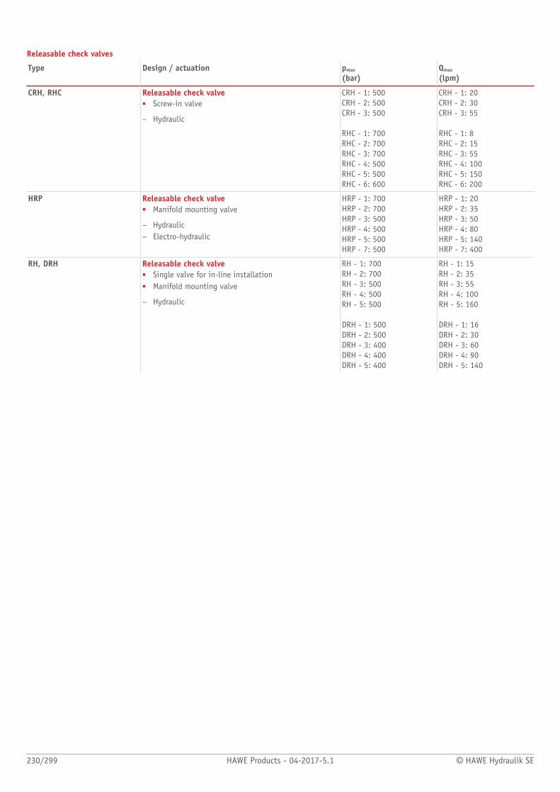
230/299 HAWE Products - 04-2017-5.1 © HAWE Hydraulik SE
Releasable check valves
Type Design / actuation pmax
(bar)Qmax
(lpm)
CRH, RHC Releasable check valve■ Screw-in valve
– Hydraulic
CRH - 1: 500CRH - 2: 500CRH - 3: 500
RHC - 1: 700RHC - 2: 700RHC - 3: 700RHC - 4: 500RHC - 5: 500RHC - 6: 600
CRH - 1: 20CRH - 2: 30CRH - 3: 55
RHC - 1: 8RHC - 2: 15RHC - 3: 55RHC - 4: 100RHC - 5: 150RHC - 6: 200
HRP Releasable check valve■ Manifold mounting valve
– Hydraulic– Electro-hydraulic
HRP - 1: 700HRP - 2: 700HRP - 3: 500HRP - 4: 500HRP - 5: 500HRP - 7: 500
HRP - 1: 20HRP - 2: 35HRP - 3: 50HRP - 4: 80HRP - 5: 140HRP - 7: 400
RH, DRH Releasable check valve■ Single valve for in-line installation■ Manifold mounting valve
– Hydraulic
RH - 1: 700RH - 2: 700RH - 3: 500RH - 4: 500RH - 5: 500
DRH - 1: 500DRH - 2: 500DRH - 3: 400DRH - 4: 400DRH - 5: 400
RH - 1: 15RH - 2: 35RH - 3: 55RH - 4: 100RH - 5: 160
DRH - 1: 16DRH - 2: 30DRH - 3: 60DRH - 4: 90DRH - 5: 140
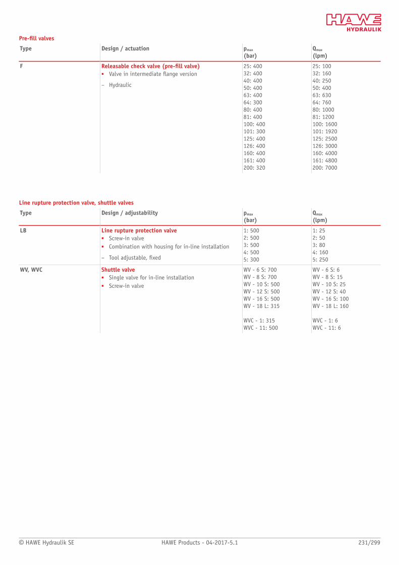
© HAWE Hydraulik SE HAWE Products - 04-2017-5.1 231/299
Pre-ll valves
Type Design / actuation pmax
(bar)Qmax
(lpm)
F Releasable check valve (pre-ll valve)■ Valve in intermediate ange version
– Hydraulic
25: 40032: 40040: 40050: 40063: 40064: 30080: 40081: 400100: 400101: 300125: 400126: 400160: 400161: 400200: 320
25: 10032: 16040: 25050: 40063: 63064: 76080: 100081: 1200100: 1600101: 1920125: 2500126: 3000160: 4000161: 4800200: 7000
Line rupture protection valve, shuttle valves
Type Design / adjustability pmax
(bar)Qmax
(lpm)
LB Line rupture protection valve■ Screw-in valve■ Combination with housing for in-line installation
– Tool adjustable, xed
1: 5002: 5003: 5004: 5005: 300
1: 252: 503: 804: 1605: 250
WV, WVC Shuttle valve■ Single valve for in-line installation■ Screw-in valve
WV - 6 S: 700WV - 8 S: 700WV - 10 S: 500WV - 12 S: 500WV - 16 S: 500WV - 18 L: 315
WVC - 1: 315WVC - 11: 500
WV - 6 S: 6WV - 8 S: 15WV - 10 S: 25WV - 12 S: 40WV - 16 S: 100WV - 18 L: 160
WVC - 1: 6WVC - 11: 6

Check valves
232/299 HAWE Products - 04-2017-5.1 © HAWE Hydraulik SE
2.5 Check valve type RK, RB, RC, RE and ER
Check valves are a type of non-return valve. They block the oil ow in one direction and
open in the opposite direction. In the closed state they have zero leakage.
The check valve type RK, RB, RC and RE can be screwed-in, type ER can be plugged-in. The
spring-loaded ball check valve type RK, RB and ER is very robust and insensitive to soiling.
The spring-loaded plate valve type RC can be screwed-in in any direction and is particularly
suitable for fast switching sequences. Type RE is a plate valve without a spring.
Type ER can be integrated directly in valves for manifold mounting. As such an addition-
al intermediate plate is not necessary for the check valve function. Type RE is suitable for
isolating pressurising loads or as a foot valve for a pump suctuion linde.
Features and benets:■ Operating pressures■ Easily machined mounting holes■ Sturdy■ Type RK, RB also available with different pre-load pressures
Intended applications:■ General hydraulic systems■ Hydraulic pre-loading
Nomen-clature:
Check valve
Design: Insert valvePlug-in valveCombination with housing for pipeconnection
pmax: 700 bar
Qmax: 620 lpm
Design and order coding example
RC 2 - E
Design with housing For pipe connection (E, F, G), type RK, RB and RC
Basic type, size Plug-in check valve Type RK, RB, size 0 ... 7Type RC, size 1 ... 3Type RE, size 0 ... 4Type RE, ER (check valve insert), size 0 to 4
Additional versions:■ Type RK with increased open-up pressure■ Type ER, stainless (size 01 ... 31)■ Type RK, RB, RC and RE with metric thread■ Type RK, RB with UNF thread
Function
RK RB ER RC REBall seated valves Shim type valves
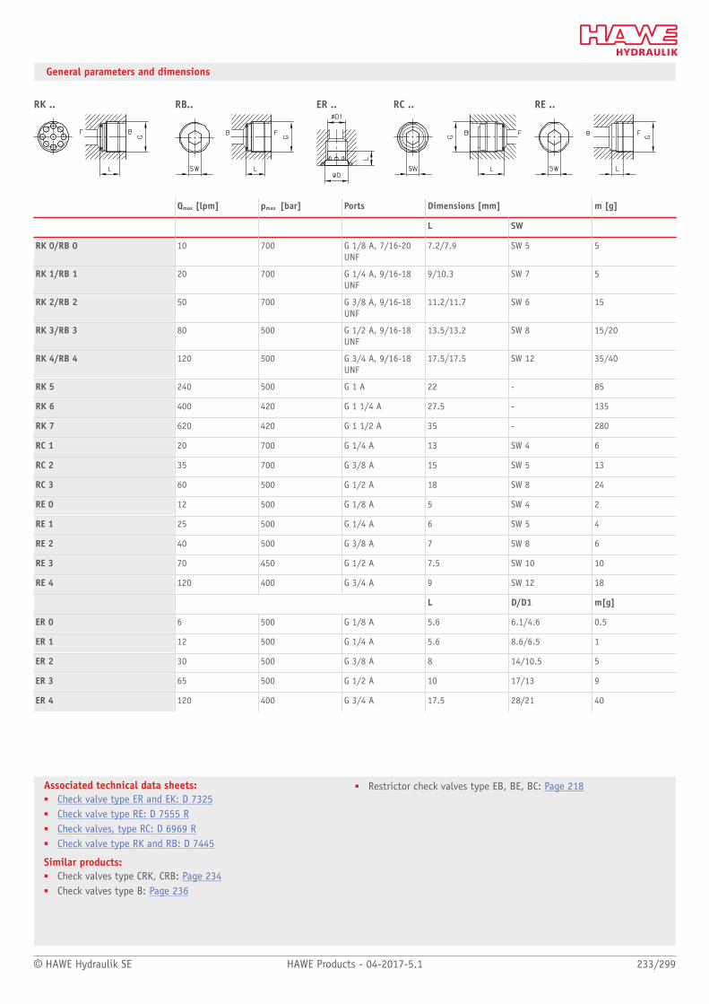
© HAWE Hydraulik SE HAWE Products - 04-2017-5.1 233/299
Associated technical data sheets:■ Check valve type ER and EK: D 7325■ Check valve type RE: D 7555 R■ Check valves, type RC: D 6969 R■ Check valve type RK and RB: D 7445
Similar products:■ Check valves type CRK, CRB: Page 234■ Check valves type B: Page 236
■ Restrictor check valves type EB, BE, BC: Page 218
General parameters and dimensions
RK .. RB.. ER .. RC .. RE ..
Qmax [lpm] pmax [bar] Ports Dimensions [mm] m [g]
L SW
RK 0/RB 0 10 700 G 1/8 A, 7/16-20UNF
7.2/7.9 SW 5 5
RK 1/RB 1 20 700 G 1/4 A, 9/16-18UNF
9/10.3 SW 7 5
RK 2/RB 2 50 700 G 3/8 A, 9/16-18UNF
11.2/11.7 SW 6 15
RK 3/RB 3 80 500 G 1/2 A, 9/16-18UNF
13.5/13.2 SW 8 15/20
RK 4/RB 4 120 500 G 3/4 A, 9/16-18UNF
17.5/17.5 SW 12 35/40
RK 5 240 500 G 1 A 22 - 85
RK 6 400 420 G 1 1/4 A 27.5 - 135
RK 7 620 420 G 1 1/2 A 35 - 280
RC 1 20 700 G 1/4 A 13 SW 4 6
RC 2 35 700 G 3/8 A 15 SW 5 13
RC 3 60 500 G 1/2 A 18 SW 8 24
RE 0 12 500 G 1/8 A 5 SW 4 2
RE 1 25 500 G 1/4 A 6 SW 5 4
RE 2 40 500 G 3/8 A 7 SW 8 6
RE 3 70 450 G 1/2 A 7.5 SW 10 10
RE 4 120 400 G 3/4 A 9 SW 12 18
L D/D1 m[g]
ER 0 6 500 G 1/8 A 5.6 6.1/4.6 0.5
ER 1 12 500 G 1/4 A 5.6 8.6/6.5 1
ER 2 30 500 G 3/8 A 8 14/10.5 5
ER 3 65 500 G 1/2 A 10 17/13 9
ER 4 120 400 G 3/4 A 17.5 28/21 40

Check valves
234/299 HAWE Products - 04-2017-5.1 © HAWE Hydraulik SE
2.5 Check valve type CRK and CRB
Check valves are a type of non-return valve. They block the oil ow in one direction and
open in the opposite direction. In the closed state they have zero leakage.
Features and benets:■ Screw-in valves
Intended applications:■ General hydraulic systems
Nomen-clature:
Check valve
Design: Screw-in valve
pmax: 500 bar
Qmax: 80 l/min
Design and order coding example
CRK 2 - 1/4
Individual connection block for pipe connection
Basic type Check valves type CRK and CRB, size 1 to 3
■ With/without tapped plug■ With/without tapped blockage/plug combination

© HAWE Hydraulik SE HAWE Products - 04-2017-5.1 235/299
Associated technical data sheets:■ Check valve type CRK, CRB and CRH: D 7712
Similar products:■ Check valves RK, RB, RC, RE, ER: Page 232
Function
CRK CRB
CRK CRB
General parameters and dimensions
CRK, CRB
Qmax
[lpm]pmax
[bar]Ports Dimensions m
[g]
G H [mm] SW 1 SW = a/f 2
CRK 1 / CRB 1 30 M 16 x 1.5 31 SW 22 SW 8 70
CRK 2 / CRB 2 50 M 20 x 1.5 35 SW 24 SW 10 110
CRK 3 80
500
M 24 x 1.5 38 SW 30 SW 12 125
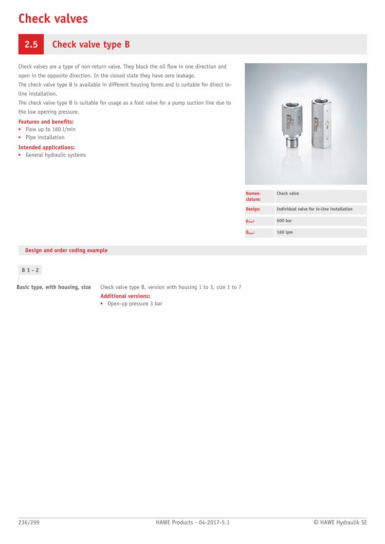
Check valves
236/299 HAWE Products - 04-2017-5.1 © HAWE Hydraulik SE
2.5 Check valve type B
Check valves are a type of non-return valve. They block the oil ow in one direction and
open in the opposite direction. In the closed state they have zero leakage.
The check valve type B is available in different housing forms and is suitable for direct in-
line installation.
The check valve type B is suitable for usage as a foot valve for a pump suction line due to
the low opening pressure.
Features and benets:■ Flow up to 160 l/min■ Pipe installation
Intended applications:■ General hydraulic systems
Nomen-clature:
Check valve
Design: Individual valve for in-line installation
pmax: 500 bar
Qmax: 160 lpm
Design and order coding example
B 1 - 2
Basic type, with housing, size Check valve type B, version with housing 1 to 3, size 1 to 7
Additional versions:■ Open-up pressure 3 bar
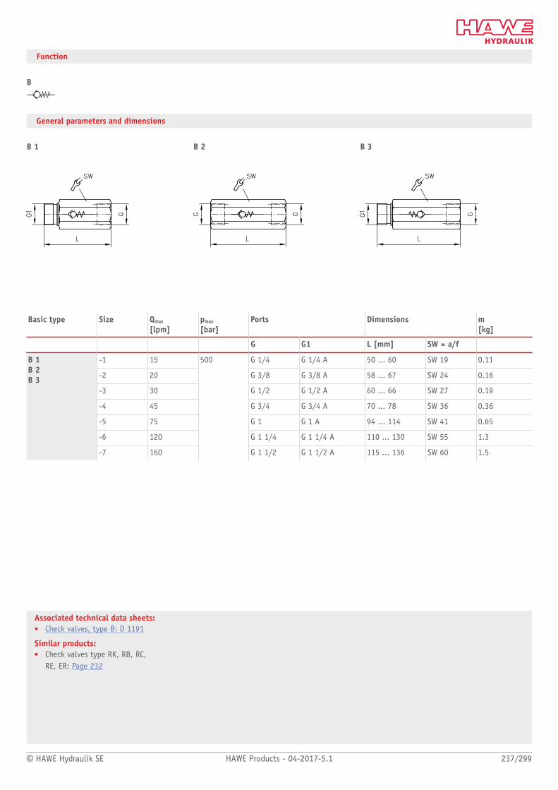
© HAWE Hydraulik SE HAWE Products - 04-2017-5.1 237/299
Associated technical data sheets:■ Check valves, type B: D 1191
Similar products:■ Check valves type RK, RB, RC,
RE, ER: Page 232
Function
B
General parameters and dimensions
B 1 B 2 B 3
Basic type Size Qmax
[lpm]pmax
[bar]Ports Dimensions m
[kg]
G G1 L [mm] SW = a/f
-1 15 G 1/4 G 1/4 A 50 ... 60 SW 19 0.11
-2 20 G 3/8 G 3/8 A 58 ... 67 SW 24 0.16
-3 30 G 1/2 G 1/2 A 60 ... 66 SW 27 0.19
-4 45 G 3/4 G 3/4 A 70 ... 78 SW 36 0.36
-5 75 G 1 G 1 A 94 ... 114 SW 41 0.65
-6 120 G 1 1/4 G 1 1/4 A 110 ... 130 SW 55 1.3
B 1B 2B 3
-7 160
500
G 1 1/2 G 1 1/2 A 115 ... 136 SW 60 1.5

Check valves
238/299 HAWE Products - 04-2017-5.1 © HAWE Hydraulik SE
2.5 Releasable check valve type CRH and RHC
Check valves with hydraulic release are a type of check valve. They block one or both
hydraulic consumer lines or are used as a hydraulically actuated drain or circulation valve.
Check valve type CRH and RHC has zero leakage when closed.
It can be screwed-in and can be integrated into control blocks. The necessary mounting
holes are straightforward to make.
Check valve type CRH and RHC is available with hydraulic release. Hydraulic release
suppresses relief surges that can occur at high pressure and with a large consumer volume.
Features and benets:■ Screw-in valve■ Pressures up to 700 bar■ Flows up to 200 l/min■ Sturdy
Intended applications:■ Industrial hydraulics■ Construction machines
Nomen-clature:
Check valve with hydraulic release
Design: Valve insert Screw-in valve
Actuation: Hydraulic
pmax: 700 bar
Qmax: 200 l/min
Design and order coding example
CRH 3 V
Function Without pre-release (-)With pre-release (V)
Basic type, size Releasable check valve type CRH, size 1 to 3 and type RHC, size 1 to 6
Additional versions:■ With higher pilot ratio (approx. 4.5 : 1)■ With sealed tapped journal and control piston■ Wth hydraulic relieve of the control piston (type RHCE)

© HAWE Hydraulik SE HAWE Products - 04-2017-5.1 239/299
Associated technical data sheets:Releasable check valves■ Check valve type CRK, CRB and CRH: D 7712■ Releasable check valve type RHC and RHCE: D 7165
Similar products:■ Type HRP: Page 240■ Type RH: Page 242
Function
CRH, RHC
CRH
General parameters and dimensions
CRH RHC
Qmax
[lpm]pmax
[bar]Release ratio Ports
(BSPP)Dimensions m
[g]
pa / pz L [mm] SW = a/f 1 SW = a/f 2
CRH 1 30 500 2.6 M 16 x 1.5 47 SW 8 SW 22 60
CRH 2 50 500 2.6 M 20 x 1.5 53 SW 10 SW 24 90
CRH 3 80 500 2.5 M 24 x 1.5 61 SW 12 SW 30 150
RHC 1 15 700 2.6 M 16 x 1.5 32 SW 6 - 20
RHC 2 25 700 2.6 M 20 x 1.5 37.5 SW 8 - 40
RHC 3 55 700 2.5 M 24 x 1.5 47 SW 10 - 70
RHC 4 100 500 2.5 M 30 x 1.5 56 SW 12 - 140
RHC 5 150 500 2.8 M 36 x 1.5 67.5 SW 14 - 250
RHC 6 200 500 2.5 M 42 x 1.5 97 SW 19 - 500

Check valves
240/299 HAWE Products - 04-2017-5.1 © HAWE Hydraulik SE
2.5 Releasable check valve type HRP
Check valves with hydraulic release are a type of check valve. They block one or both
hydraulic consumer lines or are used as a hydraulically actuated drain or circulation valve.
In the closed state the check valve type HRP has zero leakage. A leakage line relieves the
rear of the control piston. Due to this separate relief the control behaviour of the valve is
independent of the pressure in the return.
A solenoid valve can be optionally ange-mounted to arbitrarily control the check valve
with the load pressure on the consumer side. The check valve type HRP is available with a
hydraulic release. Hydraulic release suppresses relief surges that can occur at high pressure
and with a large consumer volume.
Features and benets:■ Manifold mounting valve for pressures up to 700 bar■ Flows up to 400 lpm■ Electrically controlled■ With hydraulic release for smooth switching
Intended applications:■ Industrial and mobile hydraulics
Nomen-clature:
Check valve with hydraulic release
Design: Manifold mounting valve
Actuation: HydraulicElectro-hydraulic
pmax: 700 bar
Qmax: 400 l/min
Design and order coding example
HRP 4 V - B 0,4 - WH 1H B 0,4-G24
Optionally with directly mounted 3/2-way directional seated valve For arbitrary open-up or for use as 2/2-waydirectional seated valve
Optionally with orice insert at control port Z For preventing decompression surges
Function Without pre-release (-)With pre-release (V)
Basic type, size Check valve with hydraulic release HRP, size 1 to 7

© HAWE Hydraulik SE HAWE Products - 04-2017-5.1 241/299
Associated technical data sheets:■ Releasable check valve type HRP: D 5116
Similar products:■ Releasable check valves type RH: Page 242■ Releasable check valve type RHV: D 3056■ Releasable check valves type CRH, RHC: Page 238■ Releasable twin check valves type DRH: Page 242
Function
HRP
General parameters and dimensions
Directly mounted 3/2-way solenoid valve
1 Flange-mounted 3/2-way solenoid valve
Qmax
[lpm]pmax
[bar]Release ratio Dimensions
[mm]m[kg]
pA / pZ H B L
HRP 1 20 700 2.9 20 25 74.5 0.25
HRP 2 35 700 3.9 25 30 78 0.4
HRP 3 50 500 4.3 35 35 83 0.7
HRP 4 80 500 3.8 35 50 103.5 1.2
HRP 5 140 500 4.0 40 60 120.5 1.9
HRP 7 V 400 500 3.0 63 100 190 8.0

Check valves
242/299 HAWE Products - 04-2017-5.1 © HAWE Hydraulik SE
2.5 Releasable check valve type RH and DRH
Check valves with hydraulic release are a type of check valve. They block one or both
hydraulic consumer lines or are used as a hydraulically actuated drain or circulation valve.
In the closed state the check valve type RH and DRH has zero leakage. The type DRH is a
twin check valve for double-acting consumers.
The check valve type RH and DRH is available with a hydraulic release. Hydraulic release
suppresses relief surges that can occur at high pressure and with a large consumer volume.
Features and benets:■ Pressures up to bar■ with hydraulic release for smooth switching
Intended applications:■ Blocking of leak-free hydraulic cylinders■ Return ow relief■ Hydraulically actuated drain or circulation valve
Nomenclature: Check valve with hydraulic releaseor twin check valve
Design: Individual valve for
■ Pipe connection■ Manifold mounting
Adjustment: Hydraulic
pmax: 700 bar
Qmax: 160 l/min
Design and order coding example
RH 3 V
Function Without pre-release (-)With pre-release (V)
Basic type, size Releasable check valve RH, size 1 to 5
DRH 3 LSS - 30 /100
Pre-charge pressure [bar]
Pressure setting [bar]
Basic type, size, function Releasable double check valve DRH, size 1 to 5
Additional versions:■ With pre-release (one or both sides)■ With shock valves (for hydraulic motors)■ With safety valve preventing slow pressure rises■ With leakage port preventing unintended open-up when pressure migrated from the control side■ Manifold mounting version (type DRH3P)
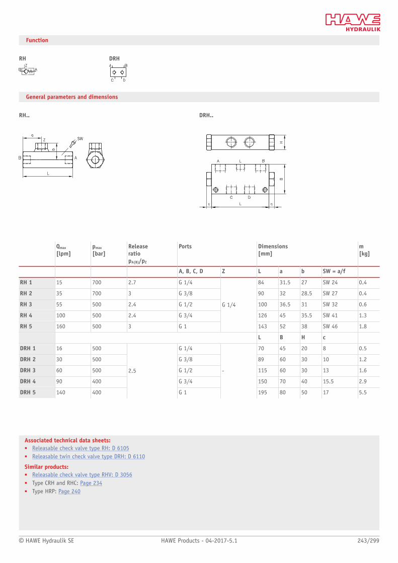
© HAWE Hydraulik SE HAWE Products - 04-2017-5.1 243/299
Associated technical data sheets:■ Releasable check valve type RH: D 6105■ Releasable twin check valve type DRH: D 6110
Similar products:■ Releasable check valve type RHV: D 3056■ Type CRH and RHC: Page 234■ Type HRP: Page 240
Function
RH DRH
General parameters and dimensions
RH.. DRH..
Qmax
[lpm]pmax
[bar]Release ratiopA(B)/pZ
Ports Dimensions [mm]
m [kg]
A, B, C, D Z L a b SW = a/f
RH 1 15 700 2.7 G 1/4 84 31.5 27 SW 24 0.4
RH 2 35 700 3 G 3/8 90 32 28.5 SW 27 0.4
RH 3 55 500 2.4 G 1/2 100 36.5 31 SW 32 0.6
RH 4 100 500 2.4 G 3/4 126 45 35.5 SW 41 1.3
RH 5 160 500 3 G 1
G 1/4
143 52 38 SW 46 1.8
L B H c
DRH 1 16 500 G 1/4 70 45 20 8 0.5
DRH 2 30 500 G 3/8 89 60 30 10 1.2
DRH 3 60 500 G 1/2 115 60 30 13 1.6
DRH 4 90 400 G 3/4 150 70 40 15.5 2.9
DRH 5 140 400
2.5
G 1
-
195 80 50 17 5.5
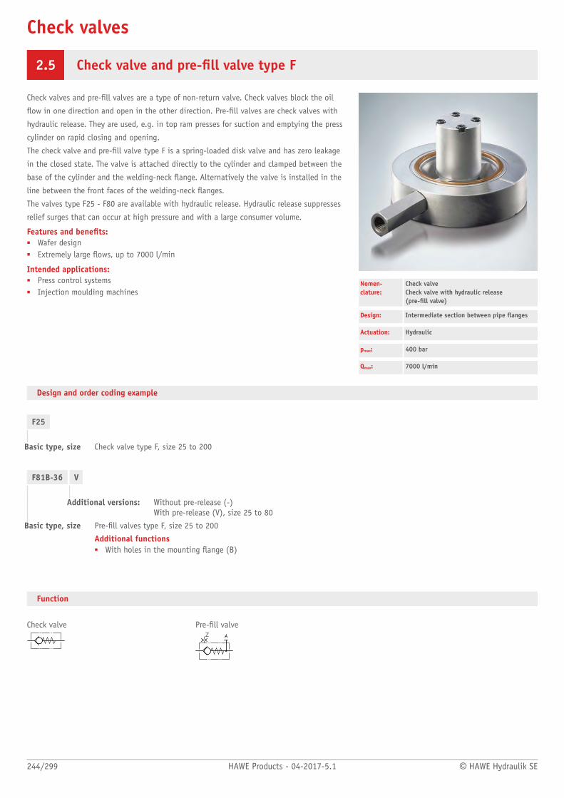
Check valves
244/299 HAWE Products - 04-2017-5.1 © HAWE Hydraulik SE
2.5 Check valve and pre-ll valve type F
Check valves and pre-ll valves are a type of non-return valve. Check valves block the oil
ow in one direction and open in the other direction. Pre-ll valves are check valves with
hydraulic release. They are used, e.g. in top ram presses for suction and emptying the press
cylinder on rapid closing and opening.
The check valve and pre-ll valve type F is a spring-loaded disk valve and has zero leakage
in the closed state. The valve is attached directly to the cylinder and clamped between the
base of the cylinder and the welding-neck ange. Alternatively the valve is installed in the
line between the front faces of the welding-neck anges.
The valves type F25 - F80 are available with hydraulic release. Hydraulic release suppresses
relief surges that can occur at high pressure and with a large consumer volume.
Features and benets:■ Wafer design■ Extremely large ows, up to 7000 l/min
Intended applications:■ Press control systems■ Injection moulding machines
Nomen-clature:
Check valve Check valve with hydraulic release (pre-ll valve)
Design: Intermediate section between pipe anges
Actuation: Hydraulic
pmax: 400 bar
Qmax: 7000 l/min
Design and order coding example
F25
Basic type, size Check valve type F, size 25 to 200
F81B-36 V
Additional versions: Without pre-release (-)With pre-release (V), size 25 to 80
Basic type, size Pre-ll valves type F, size 25 to 200
Additional functions■ With holes in the mounting ange (B)
Function
Check valve Pre-ll valve

© HAWE Hydraulik SE HAWE Products - 04-2017-5.1 245/299
Associated technical data sheets:■ Check valve and pre-ll valve type F: D 6960
General parameters and dimensions
Check valve Pre-ll valve
Qmax
[lpm]pmax
[bar]Release ratio Dimensions
[mm]m[kg]
Check valve Pre-ll valve pA / pZ D H1 H2 H3 Check valve Pre-ll valve
F 25 F 25-12 100 4.3 83 26 36 43 1 1.1
F 32 F 32-16 160 3.6 93 27 45 55 1 1.2
F 40 F 40-20 250 3.9 108 28 48.5 60 1.4 1.7
F 50 F 50-25 400 4.2 128 29 59 72 2 2.4
F 63 F 63-30 630 4.2 143 33.5 69 83 2.8 3.4
F 64 B-30 760 4,2 143 33,5 69 83 2,8 3,4
F 80 F 80-36 1000 4.5 169 38.5 83 97.5 4.4 5.2
F 81 B-36 1200 4,5 169 38,5 83 97,5 4,4 5,2
F 100 F 100-45 1600 4.3 212 44 97 118 9.9 11.7
F 101 B-45 1920 4,3 212 44 97 118 9,9 11,7
F 125 F 125-60 2500 4.3 248 51 127 155 15.8 19.6
F 126 B-60 3000 4.3 248 65 - 175 - 19.7
F 160 F 160-76 4000 4.3 310 70 182 233 43 50
F 161 B-76 4800
400
4.3 310 85 - 245 - 44
F 200 F 200-100 7000 320 4.0 420 150 250 300 114 120

Check valves
246/299 HAWE Products - 04-2017-5.1 © HAWE Hydraulik SE
2.5 Line rupture protection valve type LB
Line rupture protection valves, also called pipe rupture protection valves are a type of
check valve. The valves are normally mounted directly on the cylinder. They prevent
uncontrolled cylinder movement in the event of a pipe rupture or hose break.
The line rupture protection valve type LB offers a high level of safety in the event of
pressure peaks. It features reproducibly accurate and secure closing at the pre-set trigger
ow rate. Higher ow rates cause a plate raised from the valve seat by a spring to be
pressed onto the housing seat by the ow forces and cause the valve to close. A variant
with orice bore in the valve plate permits a low ow rate in the locking direction. Type LB
is available as a screw-in valve or in a housing version for in-line installation.
The line rupture protection valve type LB is used in industrial vehicles, lifting platforms
and lifting equipment.
Features and benets:■ Pressures up to 500 bar
Intended applications:■ Industrial trucks■ Lifting devices
Nomen-clature:
Line rupture safety valve
Design: Insert valveCombination with housing for pipeconnection
Adjustment: Fixed
pmax: 500 bar
Qmax: 160 l/min
Design and order coding example
LB 2 G 1,0 - 25
Response ow [lpm] Trigger volumetric ow QA in l/min
With/without orice Orice diameter 0.5 / 0.8 / 1.0 / 1.2 / 1.5 / 2 (dep. on type and size)
Design ■ Screw-in valve (C)■ Design with housing (F, G)■ Fitting
Basic type, size: Line rupture safety valve type LB, size 2 to 4
■ Version with imperial thread■ Version with metric thread■ Design with UNF thread
Function
LBSimplied DetailedSeries With orice

© HAWE Hydraulik SE HAWE Products - 04-2017-5.1 247/299
Associated technical data sheets:■ Line rapture protection valves, type LB: D 6990■ Line rupture safety valves type LB.E
as a screw joint: Sk 6990 E
General parameters and dimensions
LB ..C LB 11(21)CScrew-in valve
Thread seal ring
LB ..G LB ..F LB 3 ELB 4 E
Valve with housing
Qmax
[lpm]pmax
[bar]Ports Dimensions
[mm]m[g]2)
G G1 L L1 L2 SW = a/f SW =a/f 1
LB 1 (C, G, F) 4 ... 25 500 G 1/4 (A) - 17.5 48 50 a/f 19 - 6 / 70
LB 11 C1) 4 ... 25 700 G 1/4 (A) - 17.5 - - - - 6 / 70
LB 2 (C, G, F) 6.3 ... 50 500 G 3/8 (A) - 21 52 58 a/f 22 - 12 / 100
LB 21 C1) 6.3 ... 45 700 G 3/8 (A) - 25 - - - - 12 / 100
LB 3 (C, G, F) 16 ... 80 500 G 1/2 (A) - 25 60 65 a/f 27 - 21 / 170
LB 4 (C, G, F) 25 ... 160 500 G 3/4 (A) - 30.5 72 78 a/f 36 - 45 / 375
LB 3 ELB 4 E
4 ... 160 500 G 1/4 A - G 3/4 A M18x1.5 - M36x2 - - 46.8 - 64.4 SW 27 - SW 41 SW 7 150/210
LB 5 80 ... 200 300 G 1 - 38 - - - - 102
1) Mounting thread, additionally sealed2) Dimensions for insert valve and/or housing version
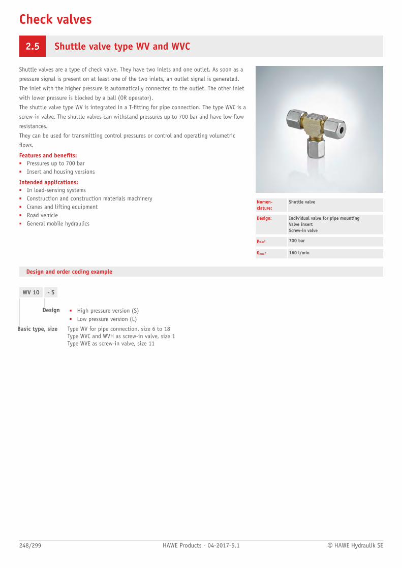
Check valves
248/299 HAWE Products - 04-2017-5.1 © HAWE Hydraulik SE
2.5 Shuttle valve type WV and WVC
Shuttle valves are a type of check valve. They have two inlets and one outlet. As soon as a
pressure signal is present on at least one of the two inlets, an outlet signal is generated.
The inlet with the higher pressure is automatically connected to the outlet. The other inlet
with lower pressure is blocked by a ball (OR operator).
The shuttle valve type WV is integrated in a T-tting for pipe connection. The type WVC is a
screw-in valve. The shuttle valves can withstand pressures up to 700 bar and have low ow
resistances.
They can be used for transmitting control pressures or control and operating volumetric
ows.
Features and benets:■ Pressures up to 700 bar■ Insert and housing versions
Intended applications:■ In load-sensing systems■ Construction and construction materials machinery■ Cranes and lifting equipment■ Road vehicle■ General mobile hydraulics
Nomen-clature:
Shuttle valve
Design: Individual valve for pipe mounting Valve insert Screw-in valve
pmax: 700 bar
Qmax: 160 l/min
Design and order coding example
WV 10 - S
Design ■ High pressure version (S)■ Low pressure version (L)
Basic type, size Type WV for pipe connection, size 6 to 18Type WVC and WVH as screw-in valve, size 1Type WVE as screw-in valve, size 11
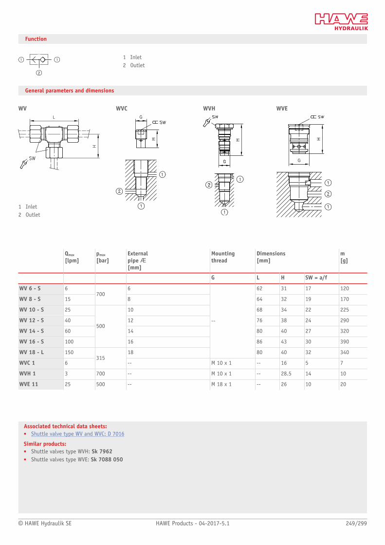
© HAWE Hydraulik SE HAWE Products - 04-2017-5.1 249/299
Associated technical data sheets:■ Shuttle valve type WV and WVC: D 7016
Similar products:■ Shuttle valves type WVH: Sk 7962■ Shuttle valves type WVE: Sk 7088 050
Function
1 Inlet2 Outlet
General parameters and dimensions
WV
1 Inlet2 Outlet
WVC WVH WVE
Qmax
[lpm]pmax
[bar]External pipe Æ[mm]
Mounting thread
Dimensions[mm]
m[g]
G L H SW = a/f
WV 6 - S 6 6 62 31 17 120
WV 8 - S 15700
8 64 32 19 170
WV 10 - S 25 10 68 34 22 225
WV 12 - S 40 12 76 38 24 290
WV 14 - S 60 14 80 40 27 320
WV 16 - S 100
500
16 86 43 30 390
WV 18 - L 150 18
--
80 40 32 340
WVC 1 6315
-- M 10 x 1 -- 16 5 7
WVH 1 3 700 -- M 10 x 1 -- 28.5 14 10
WVE 11 25 500 -- M 18 x 1 -- 26 10 20

Hydraulic cylinders and hydraulic motors
250/299 HAWE Products - 04-2017-5.1 © HAWE Hydraulik SE
Hydraulic clamps type HSE and HSA 252
Axial piston motor type M60N 254
Hydraulic clamps type HSE and HSA
Hydraulic motortype M60N

© HAWE Hydraulik SE HAWE Products - 04-2017-5.1 251/299
Hydraulic cylinders
Type Nomenclature / design pmax
(bar)HStroke
(mm)
HSE, HSA Hydraulic clamps■ Screw-in version■ Manifold mounting
HSE - 12: 500HSE - 16: 500HSE - 20: 500HSE - 24: 500
HSA - 32: 500HSA - 40: 500
HSE - 12: 8HSE - 16: 12HSE - 20: 20HSE - 24: 20
HSA - 32: 20HSA - 40: 25
Hydraulic motors
Type Nomenclature / design pmax
(bar)Vmax
(cm3/rev)
M60N Axial piston xed motor
Intended applications:■ Machines for forestry and agricultural purposes■ Fan drives■ Construction machines■ Municipal trucks
Features and benets:– Optimised power-to-weight ratio– Rotation speed– Different shaft and ange versions
Operation/peak:012: 350/400017: 350/400025: 350/400034: 350/400047: 350/400064: 350/400084: 350/400108: 350/400
012: 12.6017: 17025: 25.4034: 34.2047: 47.1064: 63.5084: 83.6108: 108

Hydraulic cylinders
252/299 HAWE Products - 04-2017-5.1 © HAWE Hydraulik SE
3 Hydraulic clamps type HSE and HSA
Hydraulic clamping cylinder generate a pressure-controlled clamping force at the piston.
Without pressure the clamping pistons return to their initial position.
The clamping cylinder type HSE is a screw-in cylinder. The type HSA is a screw-on cylinder.
Very high forces can be transmitted in a very small space in xtures.
The clamping cylinder type HSE and HSA is used in machine tools, machining centres and
chucks for clamping, fasten, lock or x workpieces, tools or machine structures.
Features and benets:■ Compact design■ Operating pressure up to 500 bar
Intended applications:■ Clamping systems■ Securing systems■ Machine tools
Nomen-clature:
Hydraulic clamps
Design: Screw-in versionManifold mounting
pmax: 500 bar
Fmax: 60000 N
Design and order coding example
HSE 24 - 15
Stroke [mm] Stroke H
Basic type, piston diameter [mm] Screw-in version type HSEManifold mounting version type HSA

© HAWE Hydraulik SE HAWE Products - 04-2017-5.1 253/299
Associated technical data sheets:■ Hydraulic clamps type HSE and HSA: D 4711
Function
HSE, HSA
General parameters and dimensions
HSE .. HSA ..Hydraulic screw-in clamps Manifold mounting hydraulic clamps
Qmax
[lpm]Stroke[mm]
Fmax
[N]Ports Dimensions
[mm]m[kg]
with 500 bar
H H1 SW = a/f A
HSE 12 2 ... 8 5500 M 20 x 1.5 20.5 ... 32.5 - SW 24 - 0.05 ... 0.08
HSE 16 3 ... 12 10000 M 24 x 1.5 26.5 ... 41.5 - SW 24 - 0.08 ... 0.12
HSE 20 4 ... 20 15000 M 30 x 1.5 28.5 ... 56 - SW 30 - 0.14 ... 0.3
HSE 24 5 ... 20 23000 M 36 x 1.5 34 ... 65 - SW 36 - 0.25 ... 0.5
HSA 32 20 40000 - - 71 - 60 1.6
HSA 40
500
25 60000 - - 85 - 70 2.5

Hydraulic cylinders and hydrostatic motors
254/299 HAWE Products - 04-2017-5.1 © HAWE Hydraulik SE
3 Axial piston motor type M60N
Axial piston motors are constant motors. They have a constant displacement and therefore
generate a xed rotation speed dependent on the ow rate.
The axial piston motor type M60N is designed for open and closed circuits and operates
based on the bent axis principle.
The motor is particularly suitable for usage in mobile applications.
Features and benets:■ Optimized power-to-weight ratio■ Rotation speed■ Different shaft and ange versions
Intended applications:■ Machines for forestry and agricultural purposes■ Fan drives■ Construction machines■ Municipal trucks
Nomen-clature:
Axial piston xed motor
Design: Individual motor
pmax: 400 bar
Vg max: 130 cm3/rev
Design and order coding example
M60N - 064 B S F N - S1 00 -G
Ports
Speed sensor With/without speed sensor
Version with housing ■ Axial version■ Radial version
Seals NBR (N), FKM (V), HNBR (H)
Flange version ■ Flange ISO 7653 - 1985■ Flange SAE J744■ Flange ISO 3019 - 2
Shaft version ■ ISO 14 parallel key splined shaft■ SAE J744 parallel key■ SAE J744 spline shaft and ange■ DIN 6885 parallel key
Rotating direction Any (B)
Nominal size
Basic type

© HAWE Hydraulik SE HAWE Products - 04-2017-5.1 255/299
Associated technical data sheets:■ Axial piston motors type M60N: D 7960 M
Similar products:■ Fixed displacement axial piston pumps type K60N: Page 30
Suitable proportional directional spool valve:■ Type EDL: Page 82■ Type PSL/PSV size 2, 3 and 5: Page 90■ Type PSLF/PSVF size 3, 5 and 7: Page 96
Suitable load-holding valves:■ Type LHK, LHDV, LHT: Page 198
Function
General parameters and dimensions
Parameters
Geom. displace-ment
Nom. pressure
Max.speed
Dimensions [mm]
m[kg]
Vg
[cm³/rev]pnom (pmax)[bar]
n[rpm]
L L1 H H1 B #D
M60N- 012 12,6 350 7500 206 46 97 147,8 - 101,6 9
M60N- 017 17,0 350 7500 206 46 97 147,8 - 101,6 9
M60N- 025 25,4 350 5900 206 46 97 147,8 - 101,6 9
M60N- 034 34,2 350 5900 206 46 97 147,8 - 101,6 9
M60N- 040 41,2 350 5300 242 56 97 147,8 - 101,6 9
M60N- 047 47,1 350 5300 242 56 109 172,5 155 127 9
M60N- 056 56,7 350 5300 242 56 109 172,5 155 127 9
M60N- 064 63,5 350 5300 242 56 109 172,5 155 127 9
M60N- 084 83,6 350 4400 264 56/74 129 192.5/205.2 - 127/152.4 18/35
M60N- 090 90,7 350 4400 264 56/74 129 192.5/205.2 - 127/152.4 18/35
M60N- 108 108,0 350 4400 264 56/74 129 192.5/205.2 - 127/152.4 18/35
M60N- 130 130,0 350 4200 264 56/74 129 192.5/205.2 - 127/152.4 18/35

Hydraulic accessories
256/299 HAWE Products - 04-2017-5.1 © HAWE Hydraulik SE
Diaphragm accumulator type AC 258
Piston type accumulator type HPS 260
Pressure switch type DG, electronic pressuretransducer type DT 262
Pressure lter type PFM 264
Fittings 266
Pressure switches type DG and analogous electronic pressure transducers

© HAWE Hydraulik SE HAWE Products - 04-2017-5.1 257/299
Hydraulic accumulators
Type Design / piston diameter p max
(bar)Nominal volume(dm3)
AC Hydraulic accumulators■ Screw-in version
13: 50040: 400202: 250603: 330725: 2501002: 2101035: 3501414: 1402001: 1002002: 2502035: 3502825: 2503225: 210
13: 0.0140: 0.04202: 0.16603: 0.60725: 0.081002: 1.001035: 1.001414: 1.402001: 1.952002: 1.902035: 1.952825: 2.803225: 0.32
HPS Piston type accumulator■ In-line installation
– 50 ... 180 mm
350 0.1 ... 40.00
Hydraulic accessories
Type Nomenclature / design Features p max
(bar)
DG Spring-loaded piston-type pressureswitch, electronic pressure switch■ Manifold mounting■ Screw-in version■ Version for pipe connection■ Electronic (analogue) pressure
transducers
Features and benets:■ Compact design■ Option of integration into the HAWE
modular system■ Operating pressures up to 1000 bar
1, 5E: 6003: 7006: 400
PFM Pressure lter
■ Pressure lter
■ Energy-efcient thanks to low backpressure
■ Long change intervals due to high dirt-holding nominal volume
■ Filter element replacement is simple andclean
250
Fittings Reducing connector, connection tting, screen lter, lter element,pressure gauge■ Screw-in version■ Version for
pipe connection
Features and benets:■ Compact design■ Option of integration into the HAWE
modular system■ Operating pressures up to 700 bar
350 ... 700

Hydraulic accessories
258/299 HAWE Products - 04-2017-5.1 © HAWE Hydraulik SE
4 Diaphragm accumulator type AC
Diaphragm accumulators are a type of hydraulic accumulator. A diaphragm separates the
compressible gas cushion from the hydraulic uid.
The diaphragm accumulator type AC is used as a source of pressurized oil. It supports or
increases the pump delivery ow or stores pressure energy, e.g. for an accumulator charge
circuit.
It is used in clamping hydraulics to compensate for volume changes in the event of
temperature fluctuations, to cover any leakage losses or for oscillation damping.
With the aid of different ttings the hydraulic accumulator type AC can be integrated
into a hydraulic system. Different installation orientations and installation positions are
possible.
Features and benets:■ Compact design■ Option of integration into the HAWE modular system■ Operating pressures up to 500 bar
Intended applications:■ Clamping systems■ Jigs■ Accumulator charging systems
Nomen-clature:
Hydro-pneumatic accumulator
Design: Screw-in version
pmax: 500 bar
Vmax: 3.5 dm3
Design and order coding example
AC 2001 /90 /3A
Connection thread (hydraulic side)
Gas pre-charge pressure [bar]
Basic type, size Hydraulic accumulator type AC
AC 40ACS 13
- 1/4- 1/4
- 200- 50 /110
Setting shut-off valve [bar]
Gas pre-charge pressure [bar]
Connection thread
Basic type, nom. volume Hydraulic miniature accumulator type AC and type ACS with shut-off valve, nom. volume in cm3
Function

© HAWE Hydraulik SE HAWE Products - 04-2017-5.1 259/299
Associated technical data sheets:■ Miniature hydraulic accumulators, type AC: D 7571■ Diaphragm accumulator type AC: D 7969
Hydraulic accessories:■ Fittings type X84: Page 266
Similar products:■ Piston type accumulator type HPS: Page 260
General parameters and dimensions
AC(S) 13 - 1/4 AC 40 - 1/4 AC 0725, AC 202, AC 322, AC 1414
AC 603, AC 1002,AC 2002, AC 2825
1 Shut-off valve
V0
[dm³]pmax
[bar]Max. gas llingpressure p0 [bar]
Ports Dimensions [mm]
m [kg]
H H1 H2 D
Hydraulic miniatureaccumulator
AC 13-1/4 0.013 500 250 G 1/4 A see illustration 0.3
ACS 13-1/4 0.013 500 250 G 1/4 A see illustration 0.3
AC 40-1/4 0.040 400 250 G 1/4 A see illustration 0.65
Hydraulic accumulator
AC 0725/1A 0.075 250 130 G 1/4 A 81 26.5 12 64 0.6
AC 202/2A 0.16 250 130 G 3/8 A 102 26.5 - 74 0.8
AC 322/2A 0.32 210 130 G 3/8 A 101.5 25 12 92.5 1.4
AC 603/3 0.6 330 130 G 1/2 149 23 - 115 3.3
AC 1002/22 1.0 210 130 M 22 x 1,5 151 25 18 136 3.5
AC 1414/2A 1.4 140 130 G 3/8 A 162 25 18 147 4.2
AC 2002/4 1.95 250 130 G 3/4 229 25 - 155 7.5
AC 2825/3 2.8 250 130 G 1/2 246 26.5 18 167 8.2
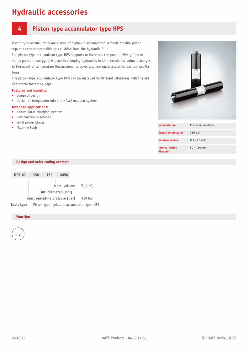
Hydraulic accessories
260/299 HAWE Products - 04-2017-5.1 © HAWE Hydraulik SE
4 Piston type accumulator type HPS
Piston type accumulators are a type of hydraulic accumulator. A freely moving piston
separates the compressible gas cushion from the hydraulic uid.
The piston type accumulator type HPS supports or increases the pump delivery ow or
stores pressure energy. It is used in clamping hydraulics to compensate for volume changes
in the event of temperature fluctuations, to cover any leakage losses or to dampen oscilla-
tions.
The piston type accumulator type HPS can be installed in different situations with the aid
of suitable fastening clips.
Features and benets:■ Compact design■ Option of integration into the HAWE modular system
Intended applications:■ Accumulator charging systems■ Construction machines■ Wind power plants■ Machine tools
Nomenclature: Piston accumulator
Operation pressure: 350 bar
Nominal volume: 0.1 - 40 dm3
Internal pistondiamater:
50 - 180 mm
Design and order coding example
HPS 10 - 350 - 160 - 0050
Nom. volume V0 [dm3]
Int. diameter [mm]
max. operating pressure [bar] 350 bar
Basic type Piston type hydraulic accumulator type HPS
Function
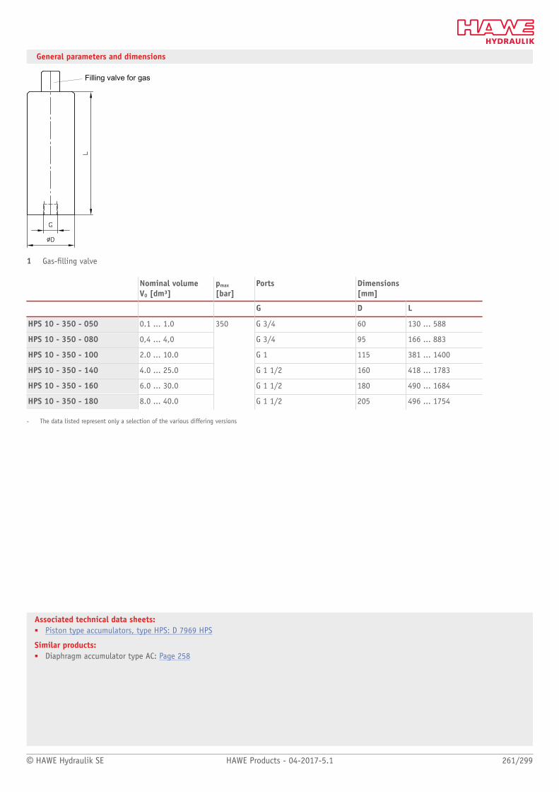
© HAWE Hydraulik SE HAWE Products - 04-2017-5.1 261/299
Associated technical data sheets:■ Piston type accumulators, type HPS: D 7969 HPS
Similar products:■ Diaphragm accumulator type AC: Page 258
General parameters and dimensions
Filling valve for gas
1 Gas-lling valve
Nominal volume V0 [dm³]
pmax
[bar]Ports Dimensions
[mm]
G D L
HPS 10 - 350 - 050 0.1 ... 1.0 G 3/4 60 130 ... 588
HPS 10 - 350 - 080 0,4 ... 4,0 G 3/4 95 166 ... 883
HPS 10 - 350 - 100 2.0 ... 10.0 G 1 115 381 ... 1400
HPS 10 - 350 - 140 4.0 ... 25.0 G 1 1/2 160 418 ... 1783
HPS 10 - 350 - 160 6.0 ... 30.0 G 1 1/2 180 490 ... 1684
HPS 10 - 350 - 180 8.0 ... 40.0
350
G 1 1/2 205 496 ... 1754
- The data listed represent only a selection of the various differing versions
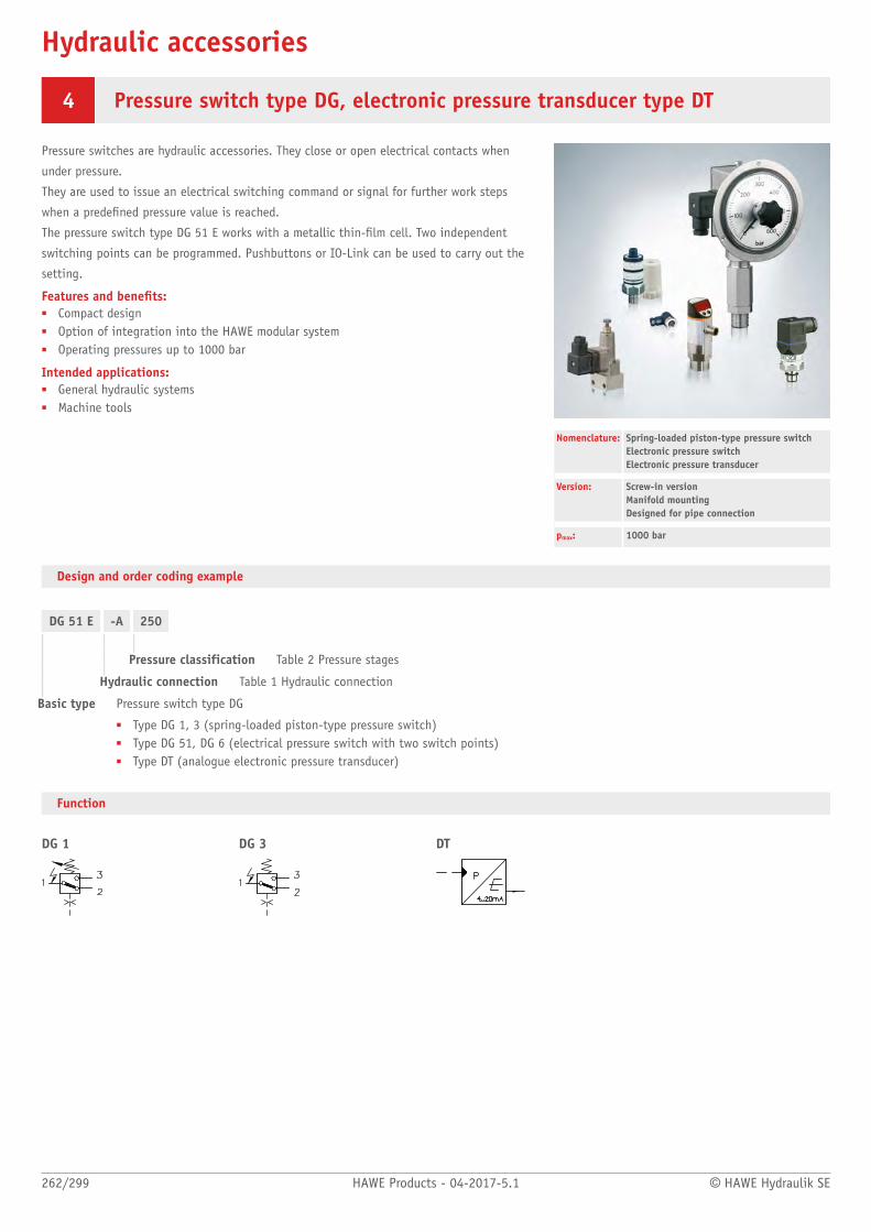
Hydraulic accessories
262/299 HAWE Products - 04-2017-5.1 © HAWE Hydraulik SE
4 Pressure switch type DG, electronic pressure transducer type DT
Pressure switches are hydraulic accessories. They close or open electrical contacts when
under pressure.
They are used to issue an electrical switching command or signal for further work steps
when a predened pressure value is reached.
The pressure switch type DG 51 E works with a metallic thin-lm cell. Two independent
switching points can be programmed. Pushbuttons or IO-Link can be used to carry out the
setting.
Features and benets:■ Compact design■ Option of integration into the HAWE modular system■ Operating pressures up to 1000 bar
Intended applications:■ General hydraulic systems■ Machine tools
Nomenclature: Spring-loaded piston-type pressure switchElectronic pressure switchElectronic pressure transducer
Version: Screw-in version Manifold mountingDesigned for pipe connection
pmax: 1000 bar
Design and order coding example
DG 51 E -A 250
Pressure classification Table 2 Pressure stages
Hydraulic connection Table 1 Hydraulic connection
Basic type Pressure switch type DG
■ Type DG 1, 3 (spring-loaded piston-type pressure switch)■ Type DG 51, DG 6 (electrical pressure switch with two switch points)■ Type DT (analogue electronic pressure transducer)
Function
DG 1 DG 3 DT
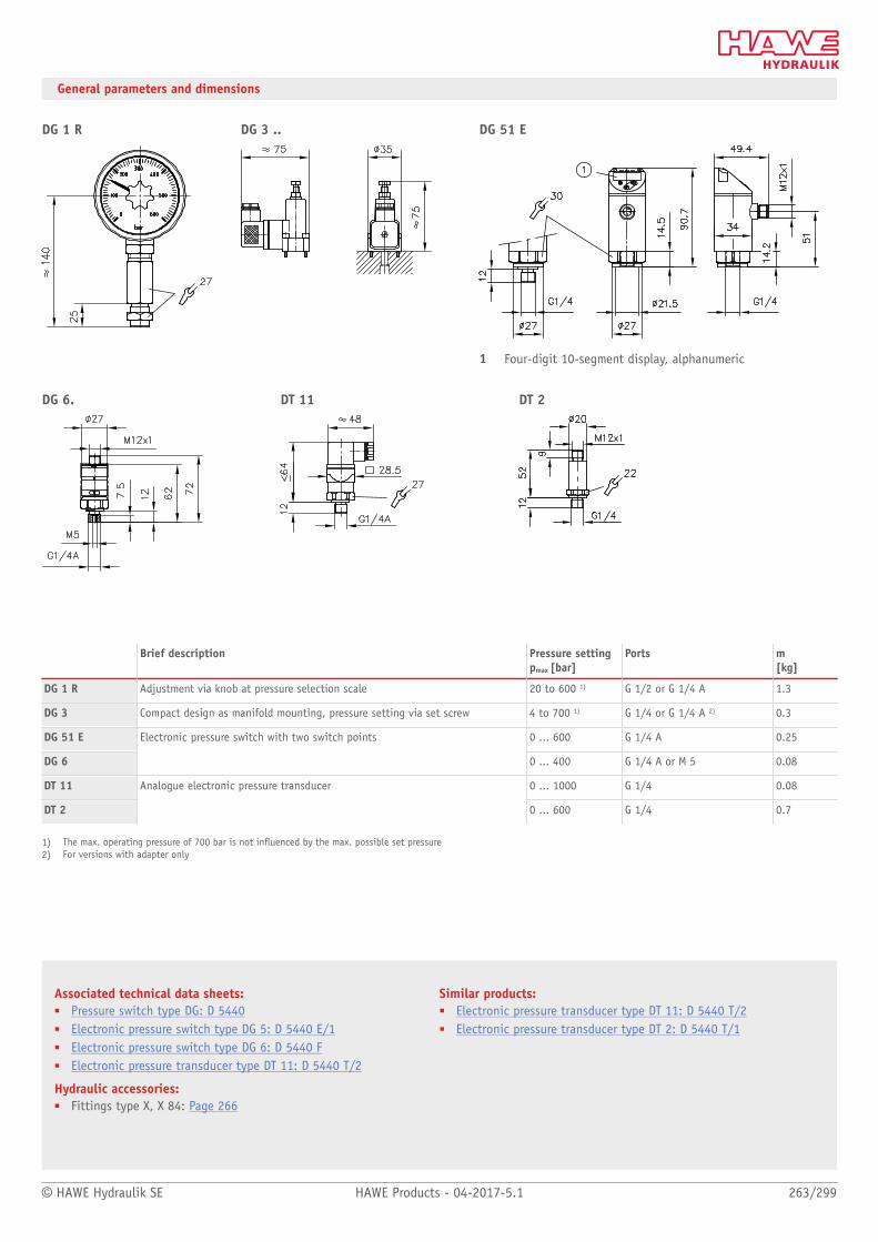
© HAWE Hydraulik SE HAWE Products - 04-2017-5.1 263/299
Associated technical data sheets:■ Pressure switch type DG: D 5440■ Electronic pressure switch type DG 5: D 5440 E/1■ Electronic pressure switch type DG 6: D 5440 F■ Electronic pressure transducer type DT 11: D 5440 T/2
Hydraulic accessories:■ Fittings type X, X 84: Page 266
Similar products:■ Electronic pressure transducer type DT 11: D 5440 T/2■ Electronic pressure transducer type DT 2: D 5440 T/1
General parameters and dimensions
DG 1 R DG 3 .. DG 51 E
1 Four-digit 10-segment display, alphanumeric
DG 6. DT 11 DT 2
Brief description Pressure settingpmax [bar]
Ports m[kg]
DG 1 R Adjustment via knob at pressure selection scale 20 to 600 1) G 1/2 or G 1/4 A 1.3
DG 3 Compact design as manifold mounting, pressure setting via set screw 4 to 700 1) G 1/4 or G 1/4 A 2) 0.3
DG 51 E 0 ... 600 G 1/4 A 0.25
DG 6
Electronic pressure switch with two switch points
0 ... 400 G 1/4 A or M 5 0.08
DT 11 0 ... 1000 G 1/4 0.08
DT 2
Analogue electronic pressure transducer
0 ... 600 G 1/4 0.7
1) The max. operating pressure of 700 bar is not inuenced by the max. possible set pressure2) For versions with adapter only

264/299 HAWE Products - 04-2017-5.1 © HAWE Hydraulik SE
4 Pressure lter type PFM
Pressure lters protect downstream hydraulic components against soiling. They are installed
in the high-pressure line typically after the pump.
The pressure lter type PFM contains a lter element through which the uid ows from
the inside to the outside. It can be replaced without drips or soiling using standard tools.
The ratio of size to performance is optimal, for this reason the lter has low pressure losses
even after absorbing a large amount of soiling.
The pressure lter type PFM is used in machine tools, industrial trucks, lifting platforms
and in general in oil hydraulics.
■ Energy-efcient thanks to low back pressure■ Long change intervals due to high dirt-holding nominal volume■ Filter element replacement is simple and clean
Intended applications:■ Machine tools■ Industrial trucks■ Lifting platforms■ General oil hydraulics
Nomenclature: Pressure lter
Version: In-line installationCan be anged
pmax: 250 bar
Qmax: 90 l/min
Design and order coding example
PFM4 -4 8 10 -R4 T -VO /-
Seal without = seriesKB = cold-resistant
Visual clogging display VE = electrically 12/24VVO = visuallyVX = retrottable- = without
Installation position T = verticalD = suspended
By-pass valve R4 = 4 barX = without
Filter neness 10 [m
Volumetric ow 5 = less than 40 l/min8 = less than 90 l/min
Port 4 = in-line installationUNF3 = in-line installation 7/8-14 UNFF = ange design
Basic type PFM4
Function
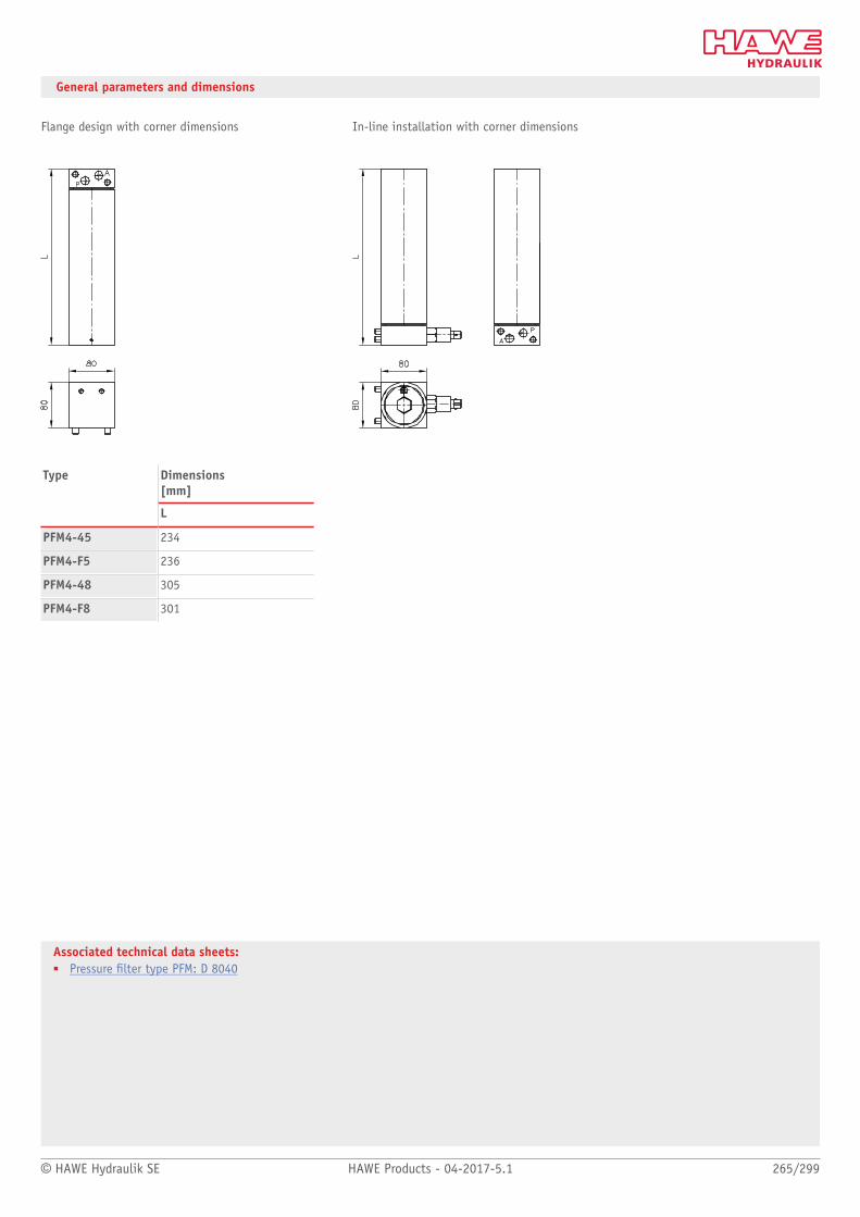
© HAWE Hydraulik SE HAWE Products - 04-2017-5.1 265/299
Associated technical data sheets:■ Pressure lter type PFM: D 8040
General parameters and dimensions
Flange design with corner dimensions In-line installation with corner dimensions
Dimensions[mm]
Type
L
PFM4-45 234
PFM4-F5 236
PFM4-48 305
PFM4-F8 301
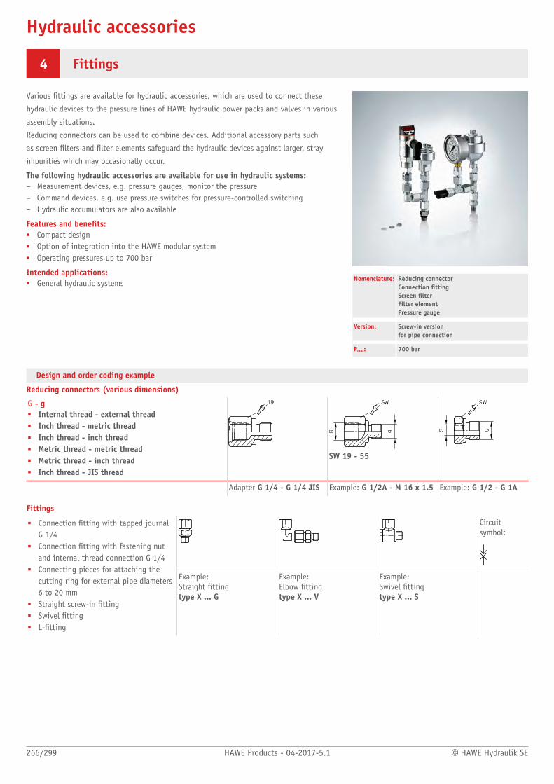
Hydraulic accessories
266/299 HAWE Products - 04-2017-5.1 © HAWE Hydraulik SE
4 Fittings
Various ttings are available for hydraulic accessories, which are used to connect these
hydraulic devices to the pressure lines of HAWE hydraulic power packs and valves in various
assembly situations.
Reducing connectors can be used to combine devices. Additional accessory parts such
as screen lters and lter elements safeguard the hydraulic devices against larger, stray
impurities which may occasionally occur.
The following hydraulic accessories are available for use in hydraulic systems:– Measurement devices, e.g. pressure gauges, monitor the pressure– Command devices, e.g. use pressure switches for pressure-controlled switching– Hydraulic accumulators are also available
Features and benets:■ Compact design■ Option of integration into the HAWE modular system■ Operating pressures up to 700 bar
Intended applications:■ General hydraulic systems
Nomenclature: Reducing connectorConnection ttingScreen lterFilter elementPressure gauge
Version: Screw-in versionfor pipe connection
Pmax: 700 bar
Design and order coding example
Reducing connectors (various dimensions)
G - g■ Internal thread - external thread■ Inch thread - metric thread■ Inch thread - inch thread■ Metric thread - metric thread■ Metric thread - inch thread■ Inch thread - JIS thread
SW 19 - 55
Adapter G 1/4 - G 1/4 JIS Example: G 1/2A - M 16 x 1.5 Example: G 1/2 - G 1A
Fittings
Circuit symbol:
■ Connection tting with tapped journalG 1/4
■ Connection tting with fastening nutand internal thread connection G 1/4
■ Connecting pieces for attaching thecutting ring for external pipe diameters6 to 20 mm
■ Straight screw-in tting■ Swivel tting■ L-tting
Example: Straight tting type X ... G
Example: Elbow tting type X ... V
Example: Swivel ttingtype X ... S

© HAWE Hydraulik SE HAWE Products - 04-2017-5.1 267/299
Associated technical data sheets:■ Reducing connector type G: D 845■ Fitting type X: D 7065■ Fitting type X 84: D 7077■ High-pressure screen lter type HF: D 7235■ Shut-off valves type AVM 8: Page 226
Fitting combinations
Please number and image caption
Connecting piece
Straight screw-infitting
L-connecting piece
Please number and image caption
Miniature accumulatorType AC
Pressure gauge
Shut-off valveType AVM 8
Consisting of:■ Connecting piece■ Straight screw-in
tting■ Swivel tting■ L-connecting piece■ Elbow tting■ Shut-off valve AVM 8■ Locking element
Example: X 84T Example: X 84U - AC 40/100-9/400
Screen lters and lter elements
Title?■ Inch thread■ Metric thread■ Screw-in strainer disc type HFC (hole Æ 0.63
mm)■ Screw-in wire mesh lter disc type HFC.. F
(lter neness approx. 100 μm)■ Also in housing version
Example HFE 3/8– Housing version with perforated
strainer (hole Æ approx. 0.5 mm)– Connection thread G 3/8(A)
Example:HFC 1/4 FScrew-in wire mesh lter disc for locationthread G 1/4, lter neness approx. 100µm

Electronics
268/299 HAWE Products - 04-2017-5.1 © HAWE Hydraulik SE
Line connector with economy circuit type MSD andothers 270
Proportional amplifier type EV 272
Proportional amplifier type EV2S 274
Programmable logic valve control type PLVC, CAN-IO 276Line connector with economy circuit
type MSD
Proportional ampliertype EV2S
Programmable logic valve controltype PLVC and CAN-IO

© HAWE Hydraulik SE HAWE Products - 04-2017-5.1 269/299
General electronic additional components
Type Nomenclature / design Features
MSD etc. ■ Line connector
– With rectifier circuit– With clamp diode– With LED– With economy circuit
Designu Power supply units
Features and benets:■ Compact design■ Functions tailored to HAWE products■ Simple installation■ Energy savings during continuous operation
Proportional ampliers
Type Nomenclature / design Features
EV ■ Module■ Card
Features and benets:■ Compact design■ Easy commissioning■ Functions tailored to HAWE products
EV2S-CAN, EV2S-BT ■ Line connector Features and benets:■ CAN bus interface■ Functions and settings tailored to HAWE products■ Precise current-controlled outputs
Electronic controls
Type Nomenclature / design Features
PLVC, CAN-IO Programmable logic control■ Modular system with
- Basic modules- Expansion modules- CAN bus nodes- - Software
Features and benets:■ Modular systems with expansion and enhancement
modules (Basic and expansion module)
■ Flexible programming■ Different interfaces
(RS 232, CAN bus, Probus)■ All output parameters can be customised■ Software function modules
(PLC programs)

General electronic additional components
270/299 HAWE Products - 04-2017-5.1 © HAWE Hydraulik SE
5 Line connector with economy circuit type MSD and others
A selection of additional electronic components is available for use in hydraulic systems.
Line connectors with and without additional functions, e.g. LEDs for switching position
monitoring and protective circuits. Line connectors with economy circuit, e.g. to minimise
the temperature at the solenoid and to save energy.
Power supply units for installation in switch cabinets.
Features and benets:■ Compact design■ Functions tailored to HAWE products■ Simple installation■ Energy savings during continuous operation
Intended applications:■ Hydraulic systems■ Mobile machines and in the industry sector
Nomenclature: Line connector with no special feature(standard)
■ With rectifier circuit■ With clamp diode■ With LED■ With economy circuit
Power supply units
Version: Line connectorModules with screw terminals
General parameters and dimensions
Male connector for solenoid valves (single and twin solenoid)
Brief description Application
No special feature (standard For all applications with no special requirements
Version with LED Display of the switching function and EMC protection (note prolonged cut-off times)
Version with clamp diode For optimum EMC protection (note prolonged cut-off times)
Version with economy circuit High reliability and prolonged lifetime of the solenoids by reducing the voltage (using pulsewidth modulation) after a dened period. Recommended for use in areas with high ambienttemperatures and/or for application where the solenoids are permanently energised (e.g. safetycircuits)
Version with rectifier circuit Use of DC solenoids with supply voltages of 110V AC, 230V AC
Male connectors with no special feature (DC voltage supply) or the version with rectifier circuit for supply voltage of 110V AC, 230V AC are
included as standard in the scope of delivery of the solenoid valve.
Power supply units for solenoid valves
Type Brief description Application
MNG Power supply unit for input voltage 230V AC and outputvoltage 24V DC, load capacity 5A
Power supply for solenoid-actuated hydraulic valves orelectrical ampliers for proportional solenoids

© HAWE Hydraulik SE HAWE Products - 04-2017-5.1 271/299
Associated technical data sheets:■ Line connector type MSD and others: D 7163■ DIN-plug with economy circuit type MSD 4 ECO for 24 V DC:
D 7833/1■ Economy circuit plug type MSE 28026 with adjustable economy
voltage: D 7832■ Power supply unit type MNG: D 7835
Additional electrical components:■ Proportional amplifier type EV, EV2S: Page 272, Page 274
■ Programmable logic valve control type PLVC and CAN node typeCAN-IO: Page 276
■ For more about electronic accessories, see "Electronics"
Example: Line connector form A in accordance with DIN EN 175 301-803
1 Cable tting Pg 9
2 Flat seal

Electronics
272/299 HAWE Products - 04-2017-5.1 © HAWE Hydraulik SE
5 Proportional amplifier type EV
Proportional ampliers actuate proportional solenoid valves by converting an input signal
into a corresponding control current.
The proportional amplifier type EV is available as a module for top-hat rail mounting or,
alternatively, as a card for a card holder. Highly precise functions are possible thanks to
the feedback measurement at the valve outputs.
The control parameters (Imin, Imax, dither, ramp times) are congured using either
pushbuttons or a potentiometer.
Features and benets:■ Compact design■ Easy commissioning■ Functions tailored to HAWE products
Intended applications:■ For controlling proportional valves■ Switch cabinet installation in an industrial environment
Nomenclature: Amplifier units for proportional solenoids
Version: Modules with screw terminalsCard version with terminal block
General parameters and dimensions
Type Brief description Application
EV 1 M 3EV 1 D
Version as a module (analogue adjustment)Version as a module (digital adjustment)
Use in switch cabinets
EV 22 K 5 Card version Card suitable for control of two twin proportional solenoids. Use in cardholder for one, or in a module rack for max. 3 amplifier cards
EV1M3
1 Standardized support bars
EV1D
1 Standard support rails
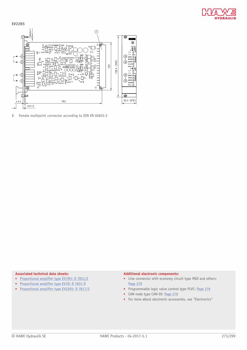
© HAWE Hydraulik SE HAWE Products - 04-2017-5.1 273/299
Associated technical data sheets:■ Proportional amplifier type EV1M3: D 7831/2■ Proportional amplifier type EV1D: D 7831 D■ Proportional amplifier type EV22K5: D 7817/2
Additional electronic components:■ Line connector with economy circuit type MSD and others:
Page 270■ Programmable logic valve control type PLVC: Page 276■ CAN node type CAN-IO: Page 276■ For more about electronic accessories, see "Electronics"
EV22K5
1 Female multipoint connector according to DIN EN 60603-2

Electronic ampliers
274/299 HAWE Products - 04-2017-5.1 © HAWE Hydraulik SE
5 Proportional amplifier type EV2S
Proportional ampliers actuate proportional solenoid valves by converting an input signal
into a corresponding control current.
Valve controls control and regulate complex mobile or stationary hydraulic systems.
The proportional amplifier type EV2S-CAN is a plug amplifier designed to be tted directly
on a proportional single-action or twin solenoid. Parameters can be congured either using
the pushbuttons and an integrated display or via CAN bus using computer software.
The proportional amplifier type EV2S-BT can be set using a smartphone and the HAWE
eControl app via Bluetooth.
Features and benets:■ CAN bus interface■ Functions and settings tailored to HAWE products■ Precise current-controlled outputs
Intended applications:■ Mobile machines and in the industry sector■ Connection of analogue proportional valves in CAN bus networks■ Closed control circuits■ Simple expansion of existing systems
Nomenclature: Amplifier plug for proportional solenoids
Version: Buttons and display or BluetoothPlug amplifier with M12 connectionPlug amplifier with 3 m cablePlug amplifierfor two single-action solenoids
General parameters and dimensions
EV2S-CAN EV2S-BT
Number of inputs
Analogue 2 2
Number of outputs
Analogue (PWM) 2 2
Interfaces
CAN bus x x
Bluetooth -- x
Buttons and display x --
Power supply 10 to 30 V DC 10 to 30 V DC
Output current 2 A 1.6 A

© HAWE Hydraulik SE HAWE Products - 04-2017-5.1 275/299
Associated technical data sheets:■ Proportional amplifier type EV2S: D 7818/1
Additional electronic components:■ proportional amplifier type EV: Page 272■ Programmable logic valve control type PLVC: Page 276■ CAN node type CAN-IO: Page 276■ For more about electronic accessories, see "Electronics"
EV2S-CAN-G-L3K
EV2S-CAN - G - M, EV2S-BT - G - M

Electronic controls
276/299 HAWE Products - 04-2017-5.1 © HAWE Hydraulik SE
5 Programmable logic valve control type PLVC, CAN-IO
Valve controls control and regulate complex mobile or stationary hydraulic systems.
The programmable valve controllers type PLVC and CAN-IO 14 are freely programmable PLC
with integrated proportional ampliers. Highly precise functions are possible thanks to the
feedback measurement at the valve outputs. The number of digital and analogue inputs and
outputs can be congured variably.
The valve control type PLVC is of modular design and can be expanded to suit the applica-
tion. It can be very straightforwardly integrated into existing systems due to the existing
interfaces.
Features and benets:■ Modular systems with expansion and enhancement modules (Basic and expansion
module)■ Flexible programming■ Different interfaces (RS 232, CAN bus, Probus)■ All output parameters can be customised■ Software function modules (PLC programs)
Intended applications:■ Construction machines■ Crane systems■ Complex lifting devices■ Machines for forestry purposes■ Machine tool and press construction
Nomenclature: Programmable logic valve control
Version: Modular concept with■ Basic modules■ Expansion modules■ Software
General parameters and dimensions
PLVC 21 PLVC 41 PLVC 8 CAN IO 14
Number of inputs 1)
Digital 13 (5 / 8) 27 (3 / 24) 17 (10 / 7) 1
Analogue 12 (4 / 8) 28 (4 / 24) 23 (11 / 12) 6 (10)
Frequency 3 (3 / -) 3 (3 / -) 3 (3 / -)
Emergency stop x x x
Number of outputs 1)
Digital 16 (8 / 8) 16 (- / 16) 13 (- / 13) 4
Analogue (PWM) 4 (4 / -) 16 (4 / 16) 16 (16 / -) 4
Analogue (0 to 10V) -- 1 (1/-) --
Relay 4 (- / 4) 8 (3 / 8) --
Auxiliary voltage -- 1 (5V DC) --
Interfaces
RS 232 x x x x
CAN bus x (x / x) x x (x / x) x
Probus x -- --
Power supply (10 to 30V DC) 10 (5 / 5) 45 (8 / 37) 32 (16 / 16) 10 to 30 V DC
Output current 2 A (max. 10 in total)
1) Max. number of inputs and outputs for each, values in brackets apply to basic module and expansion modules

© HAWE Hydraulik SE HAWE Products - 04-2017-5.1 277/299
Associated technical data sheets:■ Programmable logic valve control with Probus type PLVC 21:
D 7845-21■ Programmable logical valve control type PLVC 41: D 7845-41■ Programmable logic valve control type PLVC 8: D 7845 M■ CAN node type CAN-IO: D 7845-IO 14
Additional electronic components:■ proportional amplifier type EV, EV2S: Page 272, Page 274■ For more about electronic accessories, see "Electronics"
Software function modules (examples):
■ Position measurement■ CAN bus communication■ Position and ow rate control■ Fault detection■ Controller for closed control circuits
■ Ganging■ Electronic ow rate distribution■ Stability■ Limit load control■ Pressure reduction
Advantage: PLC programming using a structured text (ST) (see above) – The customer can customise the control at any time.
PLVC 21
PLVC 8
PLVC 41
CAN-IO 14

Appendix
278/299 HAWE Products - 04-2017-5.1 © HAWE Hydraulik SE
6 Hydraulic uids – notes for selection
The performance of a hydraulic system depends to a large extent on the quality of the hydraulic uid used.
The hydraulic uid should essentially be selected according to the operating conditions, such as
■ Temperature (see viscosity classes)■ Nomenclature (possible ban on certain hydraulic uids due to undesired reactions with metals, seals, etc.)■ Usage type (e.g. environmentally compatible hydraulic uids)■ Surroundings (use of existing hydraulic uids)
Overview of temperature and viscosity
Temperature range: Surrounding area: -40 to +80°CException:air-powered pumps type LP (+5 to +80°C)Hydraulic uid: -25...+80°CPlease observe viscosity range and any additional restrictions.
Start temperature: Down to -40°C permissibleObserve start viscosities as long as the steady-state temperature is at least 20K higher forsubsequent operation!Biologically degradable or re inhibiting pressure uids generally not over max. +60...+70°C.
Viscosity range: Min. approx. 4 mm2/s,Max. approx. 1500 mm2/sOptimal operating range approx. 10...500 mm2/s

© HAWE Hydraulik SE HAWE Products - 04-2017-5.1 279/299
Mineral oils
Hydraulic uid Characteristics Unusual features / restrictions
■ Hydraulic oils HLP (DIN 51524-2)
Mineral oil with additives improvingcorrosion, oxidation and wear protection
Common hydraulic uid
■ Hydraulic oils HL (DIN 51524-1)
Mineral oil without wear protectingadditives
Not suitable for any types of gear pump due to the lack ofwear protection additives.
■ No pumps and power packs with gear pumps type RZ, Z■ No compact hydraulic power packs HC, KA, MP, MPN,
HK, HKL
■ Hydraulic oils HVLP (DIN 51524-3)
Mineral oil with same additives as HLP, butwith increased viscosity index for use inhigher temperature ranges
The viscosity index correctors have a negative effecton the shear strength (viscosity loss approx. 30%when loaded), demulsifying behaviour and air releasecharacteristics, for example.Only use if required due to temperature range.Oil manufacturer must be consulted!
■ Unalloyed oils H, e.g.- Lubricating oils (DIN 51524-1)- White oils (e.g. NSF H1)
Mineral oil without additives Due to lack of additives only suitable for systems in thestandby mode (S2 or S3 mode) (low lubricity). White oilsare mostly used in systems with possible contact withfoodstuffs.
■ Hydraulic oils PAO (testedfor compliance withDIN 51524-1 and DIN 51524-2)
Mineral oil with additives improvingcorrosion, oxidation and wear protection
See information on hydraulic oils HVLP
■ Special uids in the aviation sector (MIL H-5606) in the marine sector (NATO H 540)
Mineral oils are based as a rule onnaphtenic oil with wide temperature range
Seals made of uor rubber FPM might be required,depending on hydraulic uid.Consult the oil manufacturer!
■ Other mineral oilsEngine oils HDATF automatic transmission uid(AQ A, sufx A)Diesel Test oil for diesel injection pump test
Mineral oils which basically weredeveloped for other application purposes
More or less suitable hydraulic uids. Pay attention to thepresence of oxidation and corrosion protection as well asmaterial compatibility (above all in relation to the seals).Attention: increased leakage with directional spoolvalves. Oil manufacturer must be consulted!
280/299 HAWE Products - 04-2017-5.1 © HAWE Hydraulik SE
Environmentally compatible hydraulic uids ISO 15380
Hydraulic uid Characteristics Unusual features / restrictions
■ Seed oil type HETG Fluids based on seed oils e.g. rape orsunower with additives show only lowtemperature resistance(< 60...70°C)
Not suitable for compact power packs type HC, KA, MP,MPN, HK, HKL, all valves with wet armature solenoids aswell as control systems utilizing many throttles. HETGuid show a tendency to gum, ageing, and sticking athigher temperatures (> 60...70°C). Their use should beavoided!
■ Polyethyleneglycol HEPGPEG-Polyethylene (may be solved inwater)PPG-Polypropylene (can't be solved inwater)
Fluids based on polyethylene glycol (PEG)Properties similar to mineral oil withregard to lifetime, lubricity and pressureresistance
No restrictions with regard to the operation behavior, butit
■ Is harmful to standard enamel (does not apply to two-pot enamel)
■ Will clog cellulose lters (use only glass ber ormetallic lters)!
■ Shows bad lubrication characteristic with materialpairings steel / light alloy or brass
■ No pumps and power packs with gear pumps type RZand Z
■ Do not use compact hydraulic power packs type HC,KA, MP, MPN, HK, HKL
■ No connection blocks with return line lter type A.F..,AF, BF, EF, FF
■ Synthetical ester HEES(carbon acid ester, diester, polyester)
Similar qualities i.e. lifetime, lubricatingcharacteristics and pressure resistance, likemineral oil
No restrictions with regard to the operation behavior. Contact with PVC should be avoided.

© HAWE Hydraulik SE HAWE Products - 04-2017-5.1 281/299
Flame-resistant hydraulic uids ISO 12922
Hydraulic uid Characteristics Unusual features / restrictions
■ HFA (pressurized water, emulsions)
Oil in water emulsion, (water content > 80%) max. temp. range approx. 60°C
There is the danger of corrosion and cavitation dueto the high water content, only use devices speciallyconstructed for this purpose (radial piston pumps type R,directional seated valves type G) Max. pump pressure 50...60% (danger of cavitation)minimum content of mineral oil > 4%
■ Do not use compact hydraulic power packs HC, KA, MP,MPN, HK, HKL – risk of short circuit
■ No paper lters – risk of blockage No connection blocks with return line lter type A.F..,AF, BF, EF, FF
■ HFC Diluted (poly) glycol solution (water content > 35%) max. temp. range up to approx. 60°C
No restrictions with regard to the operation behavior, butit
■ Incompatible with zinc■ No paper lters – risk of blockage
No connection blocks with return line lter type A.F..,AF, BF, EF, FF
■ Will clog cellulose lters (use only glass ber ormetallic lters)!
■ Shows bad lubrication characteristic with materialpairings steel/light alloy or brass
■ No compact hydraulic power packs HC, KA, MP, MPN,HK, HKL
■ HFD HFDR phosphoric esterHFDU polyolester
Fluids without water content, propertiessimilar to mineral oil
Normal operation possible Restrictions:
■ Requires seals out of FPM (FKM) (see also section "Seals")
■ Oil manufacturer must be consulted!
Special uids
Hydraulic uid Characteristics Unusual features / restrictions
■ AT-Brake uid Brake uid based on glycol (DOT 4)
No restrictions with regard to the operation behaviour,but devices must be equipped with EPDM or SBR seals (see "Seals" section)No compact hydraulic power packs type HC, KA, MP, MPN,HK, HKL

282/299 HAWE Products - 04-2017-5.1 © HAWE Hydraulik SE
Viscosity grade selection
From the 18 viscosity classes (ISO VG) listed in the standard “ISO viscosity classification for liquid lubricants” (DIN ISO 3448), the ranges ISO
VG10 to ISO VG68 are relevant for hydraulic systems. The number after "ISO VG" corresponds to the nominal viscosity at a reference temperature of
40°C. The temperature behaviour displayed in the diagram corresponds to that of mineral hydraulic oils. The characteristic curve increase of HVLP
and the environmentally compatible hydraulic uids is atter, indicating that the temperature effect is lower.
Due to manufacturer-related differences, the following benchmark gures are to be claried and compared with the permissible viscosity ranges:
■ Viscosity at 40°C■ Viscosity at the lowest (estimated or demanded) temperature■ Viscosity at the highest (presumed, required) temperature
(to guarantee a good seal life ≤ 80°C!)
Temperature / viscosity curve
1 Optimum range
2 Reference temperature
DIN ISO 3448
Guide lines for selection■ VG10, VG15
Systems intended for short time operation or use in the open or forclamping devices. Systems intended for continuous operation (for use in the open, operation in winter only)
■ VG22, VG32 General use (when used outside, only summer operation)
■ VG46, VG68 Systems in closed rooms at ambient temperatures up to 40°C or tropical conditions

© HAWE Hydraulik SE HAWE Products - 04-2017-5.1 283/299
Hydraulic uid ltration
Fine contamination (e.g. debris and dust) or contamination in the macro range (e.g. wear debris, rubber particles from hoses and seals) may
significantly impair the function of a hydraulic system.
Maintain the following hydraulic uid purities (assuming a thorough ushing has taken place prior to the date of commissioning):
Recommended purity of thehydraulic uid
ISO 4406
Recommended lter neness
Devices Note
21/18/15...19/17/13 β16...25 ≥ 75 Radial piston and gear pumps,valves, cylinders (use in generalmechanical engineering)
20/17/14...18/15/12 β6...16 ≥ 75 Prop. pressure and ow controlvalves
19/17/14 β6...16 ≥ 75 Variable displacement axial pistonpumps
The purity degree of the hydraulic uid isespecially important for the repeatabilityaccuracy with proportional valves.It should be noted that new hydraulic uid"from the barrel" does not necessarily fullthe highest cleanliness requirements.
Lower limits must be applied for pressure above 250 bar
Service life of the hydraulic uid
The aging of hydraulic uids is caused by shearing processes, cracking induced by high temperatures (gumming), mixing with (condensed) water
or reaction with other materials (e.g. metal) in the system (sludging). A major factor for the service life of the uid is beside the anti-shear
additives of the uid the lay-out of the system e.g. tank size, operation temperature, number and design of throttling sections.
Besides the properties of the hydraulic uid itself (e.g. due to additives for high shear stability), the design of the hydraulic control system (e.g.
tank size, steady-state temperature, number and type of throttling points) has a major inuence on this.
The following points are to be noted:
■ Service temperature in the tank < 80°C (mineral oils, hydraulic uids with low water content) Avoid higher temperatures – Service life reduction – (+10K corresponds to half servicelife)
■Rotational conditions of hydraulic uid
- Approx. 0.2...0.4/min for conventional hydraulic power packs - Approx. ...1/min in mobile hydraulics - Approx. ...4/min for compact hydraulic power packs in standby or load/no load operation
■ Control of the hydraulic uid on a regular base (uid level, contamination, coloring index, neutralization value etc.)■ Change of the hydraulic uid on a regular base (depending on uid type and application conditions)
Guideline:- approx. 4000 ... 8000 h (mineral oil)- approx. 2000 h (other hydraulic uids)- or at least annuallyTake into account notes of the uid manufacturer!
284/299 HAWE Products - 04-2017-5.1 © HAWE Hydraulik SE
Changing the hydraulic uid
Do not mix different types of hydraulic uids! This may lead to undesirable chemical reactions causing sludge, resinification etc.
The relevant manufacturers should be consulted when switching between different hydraulic uids. In all cases, the whole hydraulic system should
be thoroughly ushed.
Interaction with seals
Any question about the compatibility with seal material should be settled with the uid manufacturer always before using a certain hydraulic
uid (except mineral oil and synthetic esters). A rough overview is given in the table at the start of this section. HAWE utilizes seals made of the
follow- ing materials as standard:
■ NBR (acrylonitrile rubber, e.g. Bunan, Perbunan) or HNBR (hydrated NBR).
Some devices are available on request with seals made of:
■ FPM FPM (also FKM, uor rubber) e.g. for uids type HFD- The coding ...-PYD should be added to the coding for HAWE devices, e.g. WN1H-G24-PYD
■ EPDM (ethylen propylen rubber) or SBR (styrene-butadiene rubber) - The coding ...-AT should be added to the coding for HAWE devices, e.g. WN1H-G24-AT (for brake uid)
Storing hydraulic uids and hydraulic components
Storage conditions for hydraulic components depend primarily on the following factors:
■ seals utilised, moistening with oil during the factory functional test
The storability of rubber materials is generally inuenced by the following factors:
■ Warmth, light, humidity, oxygen, ozone
As far as possible, components should be de-energised and without deformation when stored. A storage temperature range of 15 to 20°C is
optimum. Relative humidity approx. 65% (+-10%). Exposure to direct sunlight or a light source with strong UV rays should be avoided.
Ozone-producing equipment (electric motors, high-voltage equipment) among other things must not be present in the storage room.
If seals are packaged in plastic bags, these should not contain any plasticisers and, if necessary, should be impermeable to UV light.
Details on storage of elastomers are also available in the following standards:
DIN 7716, MIL-HDBK-695, SAE ARP5316D, SAE AS 1933, DIN 9088.
Hydraulic uids can be stored for an unlimited period in sealed containers supplied by the manufacturer, as no chemical reactions take place. The
presence of atmospheric oxygen, dust and moisture can lead to more or less rapid oxidation and resinification, depending on the type of oil and
its additives.
A dark room with virtually constant temperature and humidity is recommended for storage of hydraulic components. The parts should be kept in a
plastic bag to protect them from dust and continuous air exchange.
A functional test (manual override, dry switching) should be carried out at least once a year to ensure operation.
Safety-related components: A six-monthly functional test on site and a regular factory inspection including seal replacement every 2 years.
When the hydraulic components are stored as described above, the risk of corrosion is low. Most external parts of HAWE components are coated
with a protective layer (galvanised, nitrided) and moistened with oil.
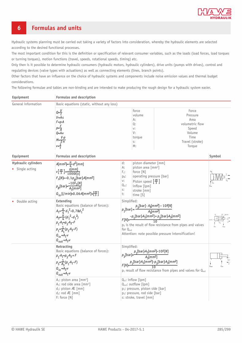
© HAWE Hydraulik SE HAWE Products - 04-2017-5.1 285/299
6 Formulas and units
Hydraulic systems planning must be carried out taking a variety of factors into consideration, whereby the hydraulic elements are selected
according to the desired functional processes.
The most important condition for this is the denition or specification of relevant consumer variables, such as the loads (load forces, load torques
or turning torques), motion functions (travel, speeds, rotational speeds, timing) etc.
Only then is it possible to determine hydraulic consumers (hydraulic motors, hydraulic cylinders), drive units (pumps with drives), control and
regulating devices (valve types with actuations) as well as connecting elements (lines, branch points).
Other factors that have an inuence on the choice of hydraulic systems and components include noise emission values and thermal budget
considerations.
The following formulae and tables are non-binding and are intended to make producing the rough design for a hydraulic system easier.
Equipment Formulas and description
Basic equations (static, without any loss)General information
forcevolumeA:Q:v:V:torques:M:
ForcePressure
Areavolumetric ow
SpeedVolumeTime
Travel (stroke)Torque
Equipment Formulas and description Symbol
Hydraulic cylinders
■ Single acting
d:A:Fs:pB:v:Qin:s:t:
piston diameter [mm]piston area [mm2]force [N]operating pressure [bar]Piston speed inow [lpm]stroke [mm]time [S]
■ Double acting ExtendingBasic equations (balance of forces):
Simplied:
p3 is the result of ow resistance from pipes and valvesfor Qout
Attention: note possible pressure intensification!
RetractingBasic equations (balance of forces):
Simplied:
p1 result of ow resistance from pipes and valves for Qout
A1: piston area [mm2]A3: rod side area [mm2]d1: piston Æ [mm]d2: rod Æ [mm]F: force [N]
Qin: inow [lpm]Qout: outow [lpm]p1: pressure, piston side [bar]p3: pressure, rod side [bar]s: stroke, travel [mm]

286/299 HAWE Products - 04-2017-5.1 © HAWE Hydraulik SE
Equipment Formulas and description Symbol
Basic equations: 1) Simplied:
Geometric volumeper revolution(piston pumps):
volumetric ow:
Middle torque:
Power:
Power rating (motor) 2)
Power output(pump)
2)
Hydraulic pumps /hydraulic motors
V: displacement [cm3]A: effective piston area [mm2]h: double stroke [mm]n: rev. rating [rpm]M: middle torque [Nm]p: pressure [bar]Δp: effective pressure [bar]Q: volumetric ow [lpm]Phydr: hydraulic performance [kW]Pmech: mechanical performance [kW]ηT : total efficiency (including volumetric andmechanical losses)
Guideline:A power rating of 1 kW for the drive is necessaryto achieve a delivery volumetric ow of Q = 1 lpmwith operating pressure p = 500 bar!
Hydraulic pump
Hydraulic motor
1) po is calculated from line and valve resistance2) incl. degree of efficiency ηT≈ 0.82
Equipment Formulas and description Symbol
ValvesDirectional valvesPressure valvesMetering valvesCheck valves
Losses of pressure by streaming uidThe pressure loss in hydraulic systems consists of:
■ Flow resistance of valves■ Flow resistance of pipes■ Flow resistance due to geometric shape (elbows etc.)
Pressure losses Δp in the valves that are caused by the volumetric ow of uid can be found in theΔp-Q characteristics of the relevant documentation. For the purposes of an initial rough design, aperformance loss of approx. 20... 30% in the overall control system can generally be expected.
Examples:Direction-al valve
Pressurelimiting valve
Flow controlvalve
Releasablecheck valve
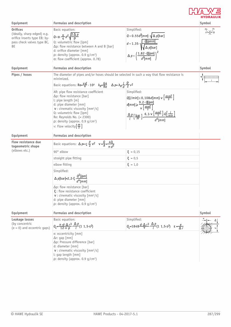
© HAWE Hydraulik SE HAWE Products - 04-2017-5.1 287/299
Equipment Formulas and description Symbol
Orices(ideally, sharp edged) e.g.orice inserts type EB; by-pass check valves type BC,BE
Basic equation:
Q: volumetric ow [lpm]Δp: ow resistance between A and B [bar]d: orice diameter [mm]ρ: density (approx. 0.9 g/cm3)α: ow coefcient (approx. 0.78)
Simplied:
Equipment Formulas and description Symbol
The diameter of pipes and/or hoses should be selected in such a way that ow resistance isminimized.
Basic equations:
Pipes / hoses
λR: pipe ow resistance coefcientΔp: ow resistance [bar]l: pipe length [m]d: pipe diameter [mm]
: cinematic viscosity [mm2/s]Q: volumetric ow [lpm]Re: Reynolds No. (< 2300)ρ: density (approx. 0.9 g/cm3)v: Flow velocity
Simplied:
Equipment Formulas and description
Basic equations:
90° elbow = 0,15
straight pipe tting = 0,5
elbow tting = 1,0
Simplied:
Flow resistance duetogeometric shape(elbows etc.)
Δp: ow resistance [bar]: ow resistance coefcient: cinematic viscosity [mm2/s]
d: pipe diameter [mm]ρ: density (approx. 0.9 g/cm3)
Equipment Formulas and description Symbol
Basic equation: Simplied:
Leakage losses(by concentric (e = 0) and eccentric gaps)
e: eccentricity [mm]Δr: gap [mm]Δp: Pressure difference [bar]d: diameter [mm]
: cinematic viscosity [mm2/s]l: gap length [mm]ρ: density (approx. 0.9 g/cm3)

288/299 HAWE Products - 04-2017-5.1 © HAWE Hydraulik SE
Equipment Formulas and description Symbol
Basic equation:
with
Volumetric losses(due to pressure increase)
p1: pressure, start [bar]p2: pressure, end [bar]Vo: initial volume [l]ΔV: change in volume [l]βP: compressibility
Simplied:
Basic equation:Volumetric losses(due to temperature rise)
1: temperature, start [°C]2: temperature, end [°C]
Δ : temperature, difference [K]Vo: initial volume [l]ΔV: volume alternation [l]βT: expansion coefcient
Simplied:
Pressure increase causedby temperature rise(without volumetriccompensation) Note: A temperature rise of trapped oil volume will cause a pressure increase! (i.e. a pressure limiting valve will
be required sometimes)Guideline: The pressure will rise by approx. 10 bar for 1 K of temperature increase.
Equipment Formulas and description Symbol
Hydraulic accumulators are intended for the supply of pressurized uid during sudden demands (quick,adiabatic pressure alternations), compensation of leakage losses or to dampen oscillations (slow,isotherm pressure alternations).
Basic equations:
isotherm (slow)
adiabatic (quick)
Hydraulic accumulatorsPressure alternations,isotherm (slow)adiabatic (quick)
po: lling pressure for the gas [bar]p1: lower operating pressure [bar]p2: upper operating pressure [bar]V1: initial volume [l]ΔV: volume alternation [l]

© HAWE Hydraulik SE HAWE Products - 04-2017-5.1 289/299
Equipment Formulas and description
Cavitation Approx. 9 % (volumetric) air are solved in oil at atmospheric pressure. There is the danger of bubble cavitationduring atmospheric pressure below 0,2 bar. These situations can occur, accompanied by sudden noise, during suctionprocess of pumps and cylinders as well as at extreme throttle sections. The hydraulic components where this occurswill show increased wear.
Equipment Formulas and description
The hydraulic power losses in a hydraulic system result in a temperature rise of the uid and the equipment whichis partly radiated to the surroundings via the surface of the system. They roughly amount 20 - 30% of the inducedperformance. The induced and the radiated heat will balance at some point after the warm-up of the system.
Basic equations:
Surface with unhindered circulation c ≈75Surface with bad circulation c ≈ 120with fan (v ≈ 2 m/s) c ≈ 40Oil/water radiator c ≈ 5
Simplied:
Thermal levelDissipation power and oiltemperature
Pv: performance loss, transformed in heat [kW]Phydr: hydraulic performance [kW]
oilmax: max. uid temperature [°C]amb: ambient temperature [°C]
A: surface of the system (tank, pipes etc.) [m2]
Conversion table
Marking Unit Factor X Unit
10 bar
1 MPa 10 bar
1 bar
Pressure p
1 psi 0.07 bar
1 NForce F
1 lbf 4.45 N
1 in 25.4 mmLength, travel, stroke l, s, h
1 ft 304.8 mm
Torque M 1 Nm
Power P 1 PS, 1 hp 0.74 kW
1 ft2 92903 mm2Area A
1 in2 645.16 mm2
1 ft3 28.92 l
1 in3 l
1 UK gal 4.55 l
Volume V
1 US gal 3.79 l
Temperatures T, 5 (°F-32)/9 1 °C
Weight m 1 lb 0.45 kg
Cinematic viscosity 1 cST 1
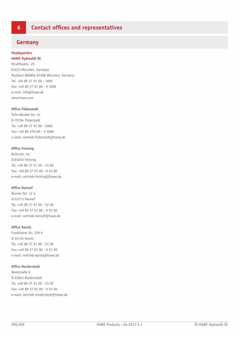
290/299 HAWE Products - 04-2017-5.1 © HAWE Hydraulik SE
6 Contact ofces and representatives
Germany
Headquarters
HAWE Hydraulik SE
Streitfeldstr. 25
81673 München, Germany
Postfach 800804 81608 München, Germany
Tel. +49 89 37 91 00 - 1000
Fax: +49 89 37 91 00 - 9 1000
e-mail: [email protected]
www.hawe.com
Ofce Filderstadt
Felix-Wankel-Str. 41
D-70794 Filderstadt
Tel. +49 89 37 91 00 - 5000
Fax: +49 89 379100 - 9 5000
e-mail: [email protected]
Ofce Freising
Kulturstr. 44
D-81653 Freising
Tel. +49 89 37 91 00 - 43 80
Fax: +49 89 37 91 00 - 9 43 80
e-mail: [email protected]
Ofce Hennef
Bonner Str. 12 d
D-53773 Hennef
Tel. +49 89 37 91 00 - 52 00
Fax: +49 89 37 91 00 - 9 52 00
e-mail: [email protected]
Ofce Kassel
Frankfurter Str. 229 b
D-34134 Kassel
Tel. +49 89 37 91 00 - 51 00
Fax: +49 89 37 91 00 - 9 51 00
e-mail: [email protected]
Ofce Norderstedt
Werkstraße 6
D-22844 Norderstedt
Tel. +49 89 37 91 00 - 53 00
Fax: +49 89 37 91 00 - 9 53 00
e-mail: [email protected]

© HAWE Hydraulik SE HAWE Products - 04-2017-5.1 291/299
International
For countries that are not listed:
HAWE Hydraulik SE
Mr. Werner Windstetter
Streitfeldstraße 25
D-81673 München
Tel. +49 89 37 91 00-0, -12 81
Fax: +49 89 37 91 00-12 69, -12 49
e-mail: [email protected], [email protected]
www.hawe.com
Angola
HAWE Hydraulik SE
Mr. Werner Windstetter
Streitfeldstraße 25
D-81673 Munich
Tel. +49 89 37 91 00-0, -12 81
Fax: +49 89 37 91 00-6281
e-mail: [email protected], [email protected]
www.hawe.com
Argentina
FLUTECNO, S.R.L.
Mr. Juan Emina
Avda. Belgrano, 615, 1º Of. G, C1092AAG Buenos Aires
Argentina
Tel. +54 11 43435168
Fax: +54 11 43421083
e-mail: [email protected]
www.flutecno.com.ar
Australia
Hawe Hydraulics Australia PTY Ltd
Mr. Steve Lettice
5/ 83-85 Montague Street
North Wollongong NSW 2500
PO Box 618 Fairymeadow 2519
Tel. +61 242 257 222
Fax: +61 242 297 622
e-mail: [email protected]
Austria
HAWE Österreich GmbH
Keltenstraße 5
A-3100 St. Pölten
Tel. +43 2749 74000-0
Fax: +43 2749 74000-40
e-mail: [email protected]
www.hawe.com
Belgium
Doedijns Hydraulics N.V. België
Mr. Jelle Beuker
Langveld Park 10, P. Basteleusstraat 2
B-1600 Sint-Pieters-Leeuw
Tel. +32 23 617 401
Fax: +32 23 617 405
e-mail: [email protected]
www.doedijns.com
Bosnia-Herzigowina
see
HAWE Hidravlika d.o.o. / Slovenia
Brazil
HIDRACOMP, LTDA
Mr. Lélio Ferrari
Rua Dr.Edgard Magalhaes Noronha, 704
BR-03480-000 Vila Nova York, Sao Paulo
Tel. +55 11 6721-1113
Fax: +55 11 6721-9302
e-mail: [email protected]
www.hidracomp.com.br
Bulgaria
Eurofluid Hydraulik Bulgaria OOD
Mr. Alexander Erschov
Vojeli Str. 3
BG-6100 Kazanlak
Tel. +359 431 634 77, +359 431 621 73
Fax: +359 431 644 74
e-mail: [email protected]
Canada
HAWE North America, Inc.
Mrs. Dani Boon
9009-K Perimeter Woods Drive
Charlotte, NC 28216
Tel. +1 704 509-1599
Fax: +1 704 509-6302
e-mail: [email protected]
www.hawehydraulics.com

292/299 HAWE Products - 04-2017-5.1 © HAWE Hydraulik SE
Chile
MARCO Industrial SPA
Mr. Rodolfo Cerda R.
Los Gobelinos 2584, Renca, Santiago
Chile
Tel. +56 2 782 4400
Fax: +56 2 26464623
e-mail: [email protected]
www.marco.cl
China
HAWE Oil-Hydraulic Technology (Shanghai) Co., Ltd.
Ms. Wang Xiaodan
155 Jindian Road
201206 PuDong / Shanghai, P.R. China
Tel. +86 21 589 996 78
Fax: +86 21 505 508 36
e-mail: [email protected]
www.hawe.com
Croatia
see
HAWE Hidravlika d.o.o. / Slovenia
Czech Republic
Eurofluid-Hydraulik CR, s.r.o.
Mr. Martin Hvézda
Chrášt’any 9
CZ-270 01 Knezeves u Rakovníka
Tel. +42 031 358 262 0, +42 031 353 101 6, +42 031 358 261 5, +42
031 353 101 7
Fax: +42 031 358 261 6
e-mail: [email protected]
www.eurofluid.cz
Denmark
Fritz Schur Teknik AS
Mr. Jørgensen
Sydmarken 46
DK-2860 Søborg
Tel. +45 70 20 1616
Fax: +45 70 20 1615
e-mail: [email protected]
www.fst.dk
Dubai
Doedijns Middle East and Africa FZE
Mr. Martijn Schols
Warehouse: G1-16, Ajman Free Zone
Dubai UAE
PO Box # 16076
Tel. +971 6 569 0639
Fax: +971 2 882 0228
e-mail: [email protected]
www.dgi-corp.com
Ecuador S.A.
Marco Ecuador
Mr. Jorge Sánchez
Av. Juan Tanca Marengo Km 0.5, No. 305
Guayaquil
Tel. +59 3 4229 2763
e-mail [email protected]
www.marco.com.ec
Egypt
Egyptian Hydraulic Engineering
Mr. Sameh Zeyada
22 Saudi Buildings Al - Sawah 11281
Cairo, Egypt
Tel. +20 224 5018-90
Fax: +20 224 5018-92
e-mail: [email protected]
www.ehehydraulic.com
Finland
HAWE Finland Oy
Mr. Mikko Vainio
Kellonsoittajantie 2
FIN-02770 Espoo
Tel. +358 10 82126-00
Fax: +358 10 82126-10
e-mail: [email protected]
www.hawe.com
France
HAWE-Otelec S.A.S.
Mr. Frédéric Chalot
2 Rue Parc des Vergers, Parc d’activités des Vergers
F-91250 TIGERY
Tel. +33 169 471 010
Fax: +33 160 792 048
e-mail: [email protected]

© HAWE Hydraulik SE HAWE Products - 04-2017-5.1 293/299
Great Britain
Koppen & Lethem Ltd.
Mr. Allan Woodhead
3 Glenholm Park, Northern Rd. Industrial Estate, Newark
GB-Nottinghamshire NG24 2EG
Tel. +44 163 667 679 4
Fax: +44 163 667 105 5
e-mail: [email protected]
www.koppen-lethem.co.uk
Greece
G. & I. Pangakis S.A.
Mr. Iannis Pangakis
Paparrigopoulou 46 & Lassani
121 32 Peristeri
Tel. +30 210 88 10 750
Fax: +30 210 88 18 659
e-mail: [email protected]
www.pangakis.gr
Hong Kong
Melchers (H.K.) Ltd., Industrial Materials Dept.
Mr. Benjamin Becker
1210 Shun Tak Centre West Tower, 168-200 Connaught Road Central,
Hong Kong
Tel. +85 22 58 91 54-4
Fax: +85 22 55 96 55-2
e-mail: [email protected]
Hungary
Jankovits Hidraulika Kft.
Mr. István Jankovits
Juharfa u. 20
HU-9027 Györ Ipari Park
Tel. +36 965 120 60
Fax: +36 96 4 195 37
e-mail: [email protected]
India
HAWE Hydraulics Pvt. Ltd.
Mrs. Cynthia Richard
No. 68, Industrial Suburb 2nd Stage, Yeshwanthpur
Bangalore 560 022, India
Tel. +91 80 419 520 00
Fax: +91 80 419 520 01
e-mail: [email protected]
Indonesia
see
Singapore
Iraq
see
Doedijns Middle East and Africa FZE / Dubai
Israel
LYA Hydraulics & Pneumatics Ltd.
Mr. Yossi Shapira
9 Lev Pesach St. North Industrial Zone
IL-71293 Lod, Israel
Tel. +97 27 32 57 00 00
Fax: +97 27 32 57 00 99
e-mail: [email protected]
www.lya.co.il
Italy
HAWE-Italiana S.r.l.
Mr. Udo Wolter
Via C. Cantù, 8
I-20092 Cinisello Balsamo (Milano)
Tel. +39 02 399 75-100
Fax: +39 02 399 75-101
e-mail: [email protected]
Japan
HAWE Japan Ltd.
Mr. Takao Yasuda
2-2, Yoshimoto-cho, Nakagawa-ku
J-Nagoya, Aichi, 454-0825, Japan
Tel. +81 52 365-1655
Fax: +81 52 365-1656
e-mail: [email protected]
www.hawe.com
Jordan
see
Doedijns Middle East and Africa FZE / Dubai
Korea
HAWE Korea Co., Ltd.
Mr. WonSam Cho
27, 1-gil, 4-sandan, Seobuk-gu, Cheon-an,
Chungnam 331-814, South Korea
Tel. +82 41 585-3800
Fax: +82 41 585-3801
e-mail: [email protected]
www.hawe.com
Kuwait
see
Doedijns Middle East and Africa FZE / Dubai

294/299 HAWE Products - 04-2017-5.1 © HAWE Hydraulik SE
Macedonia
see
HAWE Hidravlika d.o.o. / Slovenia
Malaysia
see
Singapore
Mexico
see
HAWE North America Inc. / USA
Morocco
Hydrautech Industrie Mécanique & Hydraulique Industrielles
Mr. Aziz Lakhdar
Rte.110 Km 14.800 Z.I Zenata
Casablanca
Tel. +21 2 624 026 887
e-mail: [email protected]
Netherlands
Doedijns Hydraulics B.V.
Mr. Jelle Beuker
P.O.Box 179
NL-2740 AD Waddinxveen
Tel. +31 182 302 888
Fax: +31 182 302 777
e-mail: [email protected]
www.doedijns.com
New Zealand
see
Hawe Hydraulics Australia PTY Ltd / Australia
Norway
Servi AS
Mr. Børre Kleven
Haugenveien 10, Postboks 3230
N-1402 Ski
Tel. +47 64 97 97 97
Fax: +47 64 97 98 99
e-mail: [email protected]
www.servi.no
Oman
see
Doedijns Middle East and Africa FZE / Dubai
Peru
Marco Peruana S.A.
Mr. Helmut Castro Aquino
Av. Sáenz Pena 1439, Callao 1
Peru
Tel: +51 1 201 3800
Fax: +51 146 594 97
e-mail: [email protected]
www.marco.com.pe
Philippines
see
Singapore
Poland
RDL Hydraulics Sp. z o.o
Mrs. Beata Block, Mr. Marcin Liss
Kaszubska 28
PL-80-297 Miszewko
Tel. +48 58 671 51 61
Fax: +48 58 671 51 64
e-mail: [email protected]
www.rdl-hydraulics.com
Portugal
ZANANCHO-HIDRÁULICO Lda.
Mr. Jorge Valente
Estrada Nacional 249-4, Lote 6
PT-2785-035 S. Domingos de Rana
Tel. +351 21 444 98 00
Fax: + 351 21 444 98 09
e-mail: [email protected]
www.zanancho.pt
Qatar
see
Doedijns Middle East and Africa FZE / Dubai
Romania
FLUPEC S.R.L. Engineering & Trading
Mr. Daniel Vasile, Mr. Adrian Mihu
Str. Zidului Nr. 3
RO-550324 Sibiu
Tel. +40 269 206 138
Fax: +40 269 210 700
e-mail: [email protected]
www.flupec.ro
© HAWE Hydraulik SE HAWE Products - 04-2017-5.1 295/299
Russia
HAWE Hydraulik SE
Mr. Alexander Ryabov
Moscow Region Krasnogorsk District, Arkhangelskoe Village 4th km of
the Ilinsky Highway, Building No. 8, ofce 517
RU-143420 Moscow
Tel. +7 910 088 78 80
Fax:
e-mail: [email protected]
www.hawe.com
Saudi Arabia
Dalil Al Souk Est.
Mr. Eng. Omar S. Alessa
P.O. Box 5874 Riyadh 11432
Saudi Arabia
Tel. +96 61 44 64 14-5
Fax: +96 61 44 64 18-9
e-mail: [email protected]
www.dalilalsouk.com
Serbia / Montenegro
see
HAWE Hidravlika d.o.o. / Slovenia
Singapore
HAWE Hydraulik Singapore Pte. Ltd.
Mr. Chee Hoong Chan
25 International Business Park, #01-59/60, German Centre
Singapore 609916, Singapore
Tel. +65 656 283 61
Fax: +65 656 283 60
e-mail: [email protected]
www.hawe.com
Slovakia Republic
Eurofluid Hydraulik SR s.r.o.
Mr. Andrej Galád
Racianska 71 (Areal VUZ)
SK-852 02 Bratislava 02
Tel. +42 12 49 10 22 66
Fax: +42 12 44 25 90 82
e-mail: [email protected]
www.eurofluid.sk
Slovenia
HAWE Hidravlika d.o.o.
Mr. Kristian Les
Petrovce 225
SI-3301 Petrovce
Tel. +386 371 348 80
Fax: +386 371 348 88
e-mail: [email protected]
www.hawe.com
South Africa
WALCH Engineering Co. (PTY) Ltd.
Mr. Marc Walch
6, Field Road, Lilianton, Boksburg North
SA-Witeld 1467, TVL
Tel. +27 118 261 411
Fax: +27 118 266 129
e-mail: [email protected]
Spain
HAWE Hidráulica, S.L.U.
Mr. Alfonso García
Polig. Ind. Almeda, c/. del Progrés, 139-141
E-08940 Cornella de Llobregat, Barcelona, Spain
Tel. +34 934 751 370
Fax: +34 934 751 371
e-mail: [email protected]
www.hawe.com
Sweden
HAWE Hydraulik Sweden AB
Mr. Jörgen Ahlstrand
Åvägen 24, Gårdshus 1, vån 2
41251 Göteburg
Tel. +46 76 466 15 84
Fax:
e-mail: [email protected]
www.hawe.com
Switzerland
HAWE-HYDRATEC AG
Mr. Kurt Hess
Dorfstrasse 37
CH-6035 Perlen
Tel. +41 417 474 000
Fax: +41 417 474 010
e-mail: [email protected]
www.hawe-hydratec.ch

296/299 HAWE Products - 04-2017-5.1 © HAWE Hydraulik SE
Taiwan
S.G.D. Engineering Co., LTD
Mr. Wan-Chin Yin, Mr. K. P. Chen
No.139-5, Mincheng St., Daliao District
Kaohsiung City 831, Taiwan (R.O.C.)
Tel. +886 773 532 77
Fax: +886 773 538 77
e-mail: [email protected]
www.sgdeng.com.tw
Thailand
Aerofluid Co. Ltd.
Mr. Kritsda
169/4 - 169/5 Moo 1, Rangsit-Nakhonnayok rd., Lampakkud
Thanyaburi
12110 Patumthanee, Thailand
Tel. +66 257 729 99
Fax: +66 257 727 00
e-mail: [email protected]
www.aerofluid.com
Turkey
Entek Otomasyon Ürünlerli San. ve Tic. A.S.
Mr. Dogan K. Haciahmet
Mahmutbey Mah. Tasocagi Yolu Cad. No: 9 Entek Plaza
Bagcilar - Istanbul 34218
Tel. +90 850 201 4141
e-mail: [email protected]
www.entek.com.tr
Ukraine
Izumrud Ltd.
Mrs. Lesia Konukh
Dekabristov Str. 7
UK-02121 Kiev, Ukraine
Tel. +38 044 560-3367
Fax: +38 044 563-6160
e-mail: [email protected]
www.qidravlika.kiev.ua
United Arab Emirates
see
Doedijns Middle East and Africa FZE / Dubai
USA
HAWE North America Inc.
Mrs. Dani Ferguson
9009-K Perimeter Woods Drive
Charlotte, NC 28216
Tel. +1 704 509-1599
Fax: +1 704 509-6302
e-mail: [email protected]
www.hawe.com
Vietnam
see
Singapore

© HAWE Hydraulik SE HAWE Products - 04-2017-5.1 297/299

© HAWE Hydraulik SE HAWE Products - 04-2017-5.1 298/299

_
HAW
E Pr
oduc
ts -
04-
2017
-5.1
HAWE Hydraulik SEStreitfeldstraße 25 | 81673 München | Postfach 80 08 04 | 81608 München | GermanyTel +49 89 379100-1000 | Fax +49 89 379100-91000 | [email protected] | www.hawe.com