EARTHQUAKES IN HAWAI‘I (GG104) 2006 1975 ~50 years of Hawai‘i seismicity.
Upload
vuongthienCategory
view
215download
0
Hawai‘i Energy and
Environmental Technologies
(HEET) Initiative
Office of Naval Research
Grant Award Number N0014-10-1-0310
TASK 4 ALTERNATIVE ENERGY SYSTEMS 4.1 OTEC Heat Exchanger:
Testing Program Annual Report
Prepared by:
Makai Ocean Engineering
Prepared for:
University of Hawai‘i at Mānoa, Hawai‘i Natural Energy Institute
December 2013

OTEC HX Testing Program Annual Report
I. Executive Summary
II. HX Test Facility Design and Operation
a. Facility Overview and Capabilities
b. HX Control Program
c. Construction and Installation Issues
d. Shakedown Lessons Learned
III. HX Development
a. Chart Industries Brazed Aluminum Heat Exchanger
b. Lockheed Martin Shell and Tube Heat Exchanger
IV. Corrosion
a. Hollow Extrusion Coupons: 18 month results
b. Flat Coupon: Brazed, FSW, Electropolished results
c. Upcoming experiments
V. Conclusion and Outlook

I. Executive Summary Heat exchangers are the single most expensive component in an Ocean Thermal Energy Conversion (OTEC) power plant. Proper heat exchanger selection is crucial to the economic viability of OTEC. Heat exchanger development must balance size, cost, and performance. To meet this goal, the OTEC Heat Exchanger (HX) Testing Program is divided into three areas: HX Performance Testing, HX Development, and Corrosion Testing. This annual report summarizes activities between January 2010 and June 2011 in the OTEC HX Testing Program.
Major accomplishments in this period include:
Design and Construction of a HX Performance Testing Facility
• Construction of the HX Testing Facility • Installation of Chart and Lockheed heat exchangers • Design, development, and validation of HX Facility Control System • Completion of Shakedown Testing
HX Development
• Design, installation, and functional testing of Chart brazed aluminum evaporator and Lockheed shell and tube condenser
Corrosion Testing
• Removal of 6-month, 1-year, and 18-month hollow extrusion corrosion samples
Major findings in this period include:
HX Testing Facility Design and Operation
• Design phase was extended due to delays in heat exchanger delivery. The extended design phase allowed for better facility design.
• Construction was smooth overall. The two big delays experienced prior to running the facility were caused by electrical inspection and leaking ammonia control valves.
• Instrument calibration and reliability is vital to testing. Manufacturer supplied calibration data is questionable. We will independently validate each sensor reading with our own calibration.
• The testing facility is equipped with high accuracy instrumentation. Compared to previous testing, lower uncertainties are expected.
• A wide range of testing conditions has been confirmed. However, higher sensitivity can be attained when testing at higher duties than during testing at low duties.
• At maximum duty, the rate of condensate flow exiting the condenser may be limited due to pipe sizes.
• Heat transfer to/from the environment (e.g., condensation on the outside of the condenser) may introduce errors in heat exchanger testing. Further investigation will be required for highly reliable performance data.
• Ammonia vapor/liquid mixture at the evaporator outlet must travel up an additional 12 feet prior to reaching the separator. This may affect evaporator performance.
• Steady state can be attained in ~ 3 minutes when control system parameters are optimized. Previous testing required approximately 1 hour prior to reaching targeted steady state conditions.
HX Development
• Lockheed shell and tube condenser was manufactured using a new Tubular Friction Stir Weld (TFSW) technique to join the tubes into the tube sheet. This technique minimizes manufacturing costs and minimizes the affected weld zone to improve corrosion resistance.
• The condenser is constructed of an aluminum alloy selected for manufacturability and corrosion resistance, illustrating the synthesis of the program’s multiple goals.
• Brazed joints in the Chart brazed aluminum evaporator were isolated from seawater exposure to protect against corrosion.
• The Chart brazed aluminum evaporator has extruded channels for seawater passages. This design is optimized for OTEC as extruded channels are unconventional in a brazed aluminum heat exchanger.
Corrosion Testing
• Uniform corrosion rates are low and comparable amongst the different alloys. • Braze joints and electropolished surfaces are susceptible to severe pitting in cold seawater. • Focus on quantifying and comparing susceptibility to localized corrosion will determine
whether aluminum is a viable heat exchanger material.
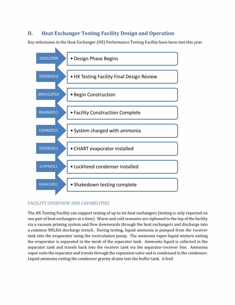
II. Heat Exchanger Testing Facility Design and Operation Key milestones in the Heat Exchanger (HX) Performance Testing Facility have been met this year.
FACILITY OVERVIEW AND CAPABILITIES
The HX Testing Facility can support testing of up to six heat exchangers (testing is only expected on one pair of heat exchangers at a time). Warm and cold seawater are siphoned to the top of the facility via a vacuum priming system and flow downwards through the heat exchangers and discharge into a common NELHA discharge trench. During testing, liquid ammonia is pumped from the receiver tank into the evaporator using the recirculation pump. The ammonia vapor-liquid mixture exiting the evaporator is separated in the mesh of the separator tank. Ammonia liquid is collected in the separator tank and travels back into the receiver tank via the separator-receiver line. Ammonia vapor exits the separator and travels through the expansion valve and is condensed in the condenser. Liquid ammonia exiting the condenser gravity drains into the buffer tank. A feed
10JUL2009 •Design Phase Begins
10FEB2010 •HX Testing Facility Final Design Review
09AUG2010 •Begin Construction
03JAN2011 • Facility Construction Complete
13JAN2011 • System charged with ammonia
25FEB2011 •CHART evaporator installed
15APR2011 • Lockheed condenser installed
03MAY2011 • Shakedown testing complete

Figure 1. Schematic of HX Testing Facility showing major components and fluid flow paths.
pump moves the liquid ammonia from the buffer tank into the receiver tank. Both ammonia pumps are located in the pump pit. During idle periods, most of the ammonia in the system will be held in the buffer and receiver tanks and in the piping in the pump pit. Reserve ammonia for the facility is stored in the storage tank.
CONTROL SYSTEM
The system is controlled using data acquisition hardware and a custom designed software program. This HX Control Program is capable of controlling the ammonia pumps, ammonia control valves, and seawater control valves manually or automatically (given predefined setpoints). In automatic mode, ammonia system parameters are monitored and the HX Control Program adjusts valves and pumps to maintain or change parameters. Ammonia system pressure and temperature are monitored at multiple locations, level is monitored in all tanks, and flow is monitored at five points. The seawater system has four pressure sensors, two temperature sensors, and one flow sensor for each water source. Sensor outputs are wired to a data acquisition cabinet located on the structure and data is collected by the HX Control Program. Along with data collection and system control, the software performs preliminary data analysis by calculating heat exchanger performance parameters and determining periods of steady state operation.
CONSTRUCTION AND INSTALLATION ISSUES
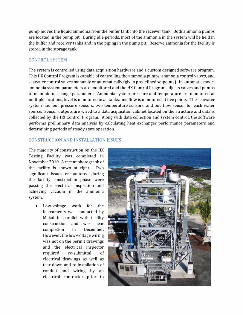
The majority of construction on the HX Testing Facility was completed in November 2010. A recent photograph of the facility is shown at right. Two significant issues encountered during the facility construction phase were passing the electrical inspection and achieving vacuum in the ammonia system.
• Low-voltage work for the instruments was conducted by Makai in parallel with facility construction and was near completion in December. However, the low-voltage wiring was not on the permit drawings and the electrical inspector required re-submittal of electrical drawings as well as tear-down and re-installation of conduit and wiring by an electrical contractor prior to

approval. Final approval for the electrical permit was not granted until March 2011. • The ammonia system piping had difficulty maintaining vacuum. Small leaks were finally
found in the ammonia control valves. One valve body had a leak and the actuators and valve stems were misaligned, causing the valve stem to bend and air to leak by. The leaks were detected after charging small amounts of ammonia vapor into the system and using litmus paper. We also found several manual ammonia valves do not seal completely and could not be used to isolate the ammonia system during subsequent installation of the Chart and Lockheed heat exchangers.
Major component issues include:
• The feed pump was initially connected with the motor leads in reverse. The feed pump performance was well below the pump curve.
• The Chart heat exchanger seawater flanges did not match the flange on the seawater piping. The blind flanges that were installed during transport were modified and used as the backing flange to correct the program.
• Ammonia control valves continue to occasionally leak from the valve stem despite careful alignment of the actuator and valve stem. Media containment units will be installed around each valve to contain any ammonia release.
SHAKEDOWN LESSONS LEARNED
Shakedown testing of the HX Testing Facility began with temporary heat exchangers in January 2010. Multiple issues involving instrumentation surfaced:
• The calibration data received from manufacturers do not appear accurate and two iterations of pressure/temperature sensor calibrations have been performed. We are still unsatisfied with the results are will be performing another calibration using a specially designed calibration apparatus.
• Ultrasonic flow sensors have also been unreliable and malfunctioned due to weather exposure. Two units have been sent back to the manufacturer for repair twice.
• The level sensor stilling well vent hole was in the wrong place in the buffer tank and missing in the receiver tank.
Key shakedown findings:
• Seawater flow is established by creating a siphon through the heat exchangers using the vacuum priming system. Seawater flow is controlled using the seawater discharge valve. Flow rates up to 4500 gpm (current NELHA limit) on both warm and cold seawater have been attained. By extrapolating the pressure at the top of the supply header at 4500 gpm, a maximum flow of 6000 gpm can be achieved while ensuring seawater pressure remains above vapor pressure.
• NELHA seawater discharge trench was able to handle the 9000 gpm combined seawater discharge rate that was tested and still had remaining capacity for higher flows.
• All control valves have some degree of hysteresis. o An algorithm to reliably position the seawater control valves has been developed.

o For the expansion valve, the minimum increment of adjustment limits our sensitivity in controlling heat exchanger pressure by as much as 5 kPa, depending on the operating conditions.
• Orientation of the ammonia evaporator outlet piping may bias data. Any liquid exiting the evaporator must be lifted by the vapor 12 feet and pass through a valve prior to reaching the separator tank. The ammonia evaporator outlet pressure sensor is located in the vertical pipe and may not provide accurate representation of evaporator exit conditions.
• How we determine steady-state is an ongoing area of research. Steady-state parameters and criteria require further refinement prior to formal heat exchanger testing.
III. Heat Exchanger Development The goal of the heat exchanger development program is to optimize OTEC heat exchangers. The optimum heat exchanger is different for warm versus cold seawater and is evaluated on the basis of cost, lifetime, and performance. Results from the corrosion program are used to evaluate lifetime and results from testing are used to evaluate performance.
Currently, two baseline heat exchangers are under testing and evaluation. The baseline evaporator is a brazed aluminum unit designed by Makai Ocean Engineering with support from Chart Industries and constructed by Chart Industries. The baseline condenser is an aluminum shell and tube unit designed and built by Lockheed Martin. These heat exchangers reflect our best guess at a good OTEC heat exchanger based on minimal data on cost, performance, and lifetime (corrosion) and will establish a baseline for future heat exchangers. Future heat exchanger designs will incorporate knowledge gained from the ongoing corrosion and testing programs.
LOCKHEED CONDENSER
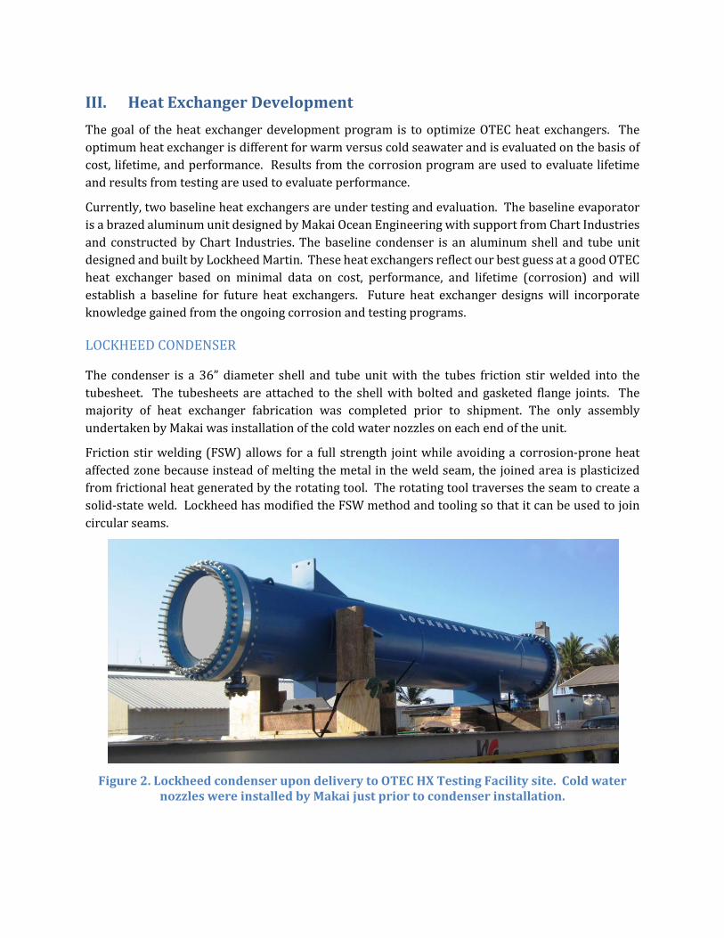
The condenser is a 36” diameter shell and tube unit with the tubes friction stir welded into the tubesheet. The tubesheets are attached to the shell with bolted and gasketed flange joints. The majority of heat exchanger fabrication was completed prior to shipment. The only assembly undertaken by Makai was installation of the cold water nozzles on each end of the unit.
Friction stir welding (FSW) allows for a full strength joint while avoiding a corrosion-prone heat affected zone because instead of melting the metal in the weld seam, the joined area is plasticized from frictional heat generated by the rotating tool. The rotating tool traverses the seam to create a solid-state weld. Lockheed has modified the FSW method and tooling so that it can be used to join circular seams.
Figure 2. Lockheed condenser upon delivery to OTEC HX Testing Facility site. Cold water
nozzles were installed by Makai just prior to condenser installation.
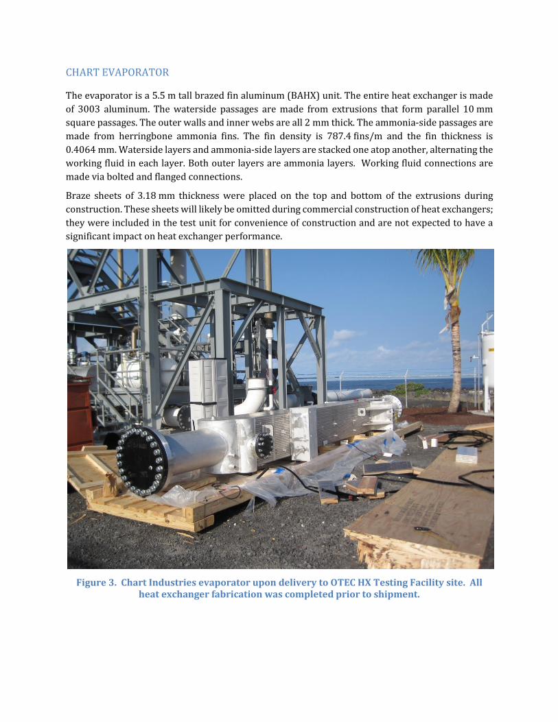
CHART EVAPORATOR
The evaporator is a 5.5 m tall brazed fin aluminum (BAHX) unit. The entire heat exchanger is made of 3003 aluminum. The waterside passages are made from extrusions that form parallel 10 mm square passages. The outer walls and inner webs are all 2 mm thick. The ammonia-side passages are made from herringbone ammonia fins. The fin density is 787.4 fins/m and the fin thickness is 0.4064 mm. Waterside layers and ammonia-side layers are stacked one atop another, alternating the working fluid in each layer. Both outer layers are ammonia layers. Working fluid connections are made via bolted and flanged connections.
Braze sheets of 3.18 mm thickness were placed on the top and bottom of the extrusions during construction. These sheets will likely be omitted during commercial construction of heat exchangers; they were included in the test unit for convenience of construction and are not expected to have a significant impact on heat exchanger performance.
Figure 3. Chart Industries evaporator upon delivery to OTEC HX Testing Facility site. All
heat exchanger fabrication was completed prior to shipment.
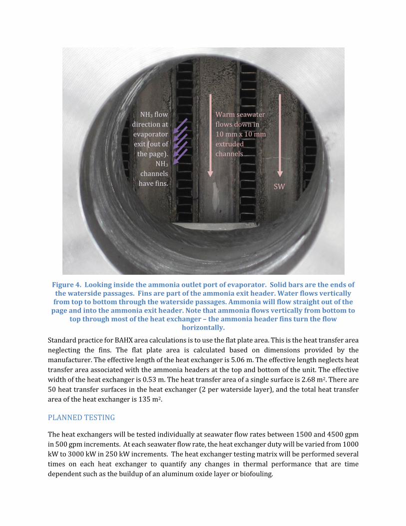
Figure 4. Looking inside the ammonia outlet port of evaporator. Solid bars are the ends of the waterside passages. Fins are part of the ammonia exit header. Water flows vertically
from top to bottom through the waterside passages. Ammonia will flow straight out of the page and into the ammonia exit header. Note that ammonia flows vertically from bottom to
top through most of the heat exchanger – the ammonia header fins turn the flow horizontally.
Standard practice for BAHX area calculations is to use the flat plate area. This is the heat transfer area neglecting the fins. The flat plate area is calculated based on dimensions provided by the manufacturer. The effective length of the heat exchanger is 5.06 m. The effective length neglects heat transfer area associated with the ammonia headers at the top and bottom of the unit. The effective width of the heat exchanger is 0.53 m. The heat transfer area of a single surface is 2.68 m2. There are 50 heat transfer surfaces in the heat exchanger (2 per waterside layer), and the total heat transfer area of the heat exchanger is 135 m2.
PLANNED TESTING
The heat exchangers will be tested individually at seawater flow rates between 1500 and 4500 gpm in 500 gpm increments. At each seawater flow rate, the heat exchanger duty will be varied from 1000 kW to 3000 kW in 250 kW increments. The heat exchanger testing matrix will be performed several times on each heat exchanger to quantify any changes in thermal performance that are time dependent such as the buildup of an aluminum oxide layer or biofouling.
Warm seawater flows down in 10 mm x 10 mm extruded channels
SW
NH3 flow direction at evaporator exit (out of
the page). NH3
channels have fins.

Data will be collected continuously, but only steady state data will be used for performance analysis. Performance parameters include: duty, net power rating, heat transfer coefficient, waterside pressure drop, and ammonia-side pressure drop. Collected data will also be compared to predicted results from heat transfer analytical models.
IV. Corrosion The goal of the corrosion testing program is to evaluate the corrosion resistance of potential heat exchanger materials and manufacturing processes used in heat exchanger construction in seawater conditions similar to the expected OTEC operating environment.
Corrosion samples currently being tested consist of:
• hollow extrusion coupons of six alloys – 1100, 3003, 5052, 6063, and two Kaiser proprietary variations
• flat coupons of three alloys with varying manufacturing processes applied o 3003 – heat treated, brazed, welded, electropolished o 6063 – friction stir welded, electropolished o 5052 – electropolished
• flat coupons of galvanized steel (cold water only) • tubular velocity coupons of 5086 and 6063
Planned corrosion samples include:
• tubular friction stir weld coupons of 6063 • large plate coupons of 3003, 5052, and 6063 with discrete manufacturing processes (e.g.,
weld lines using various filler materials) • Chart replica
Three seawater sources are available for corrosion testing: warm surface seawater, cold seawater from 674-m, and cold seawater from 915-m. Cold seawater is untreated. Warm seawater has been treated with 100 ppb chlorine derived from sodium hypochlorite (bleach) for 1 hour a day to control biofouling. Chlorine treatment has been ineffective in controlling biofouling. Biofouling in the flexible hose has also been observed in both cold seawater sources. To discourage biofouling, the corrosion testing rooms have been darkened and chlorination in warm seawater has been increased to continuous 70 ppb treatment. Proposals to research different biofoulant controls have been submitted.
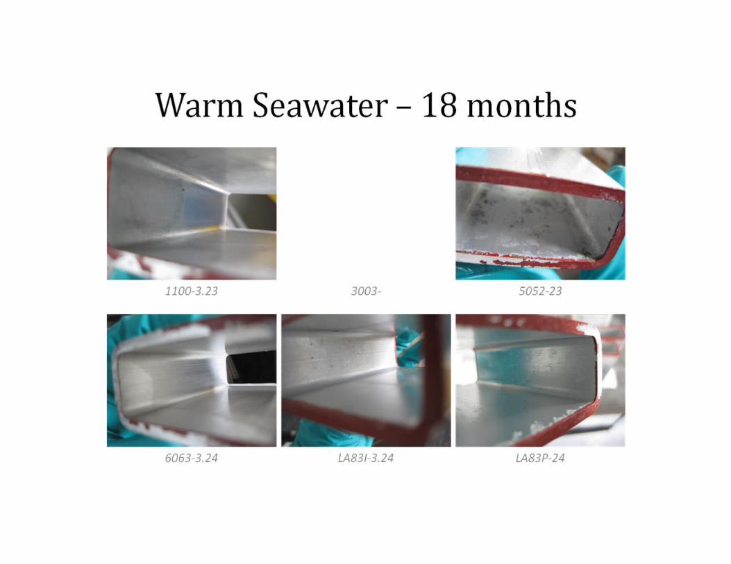
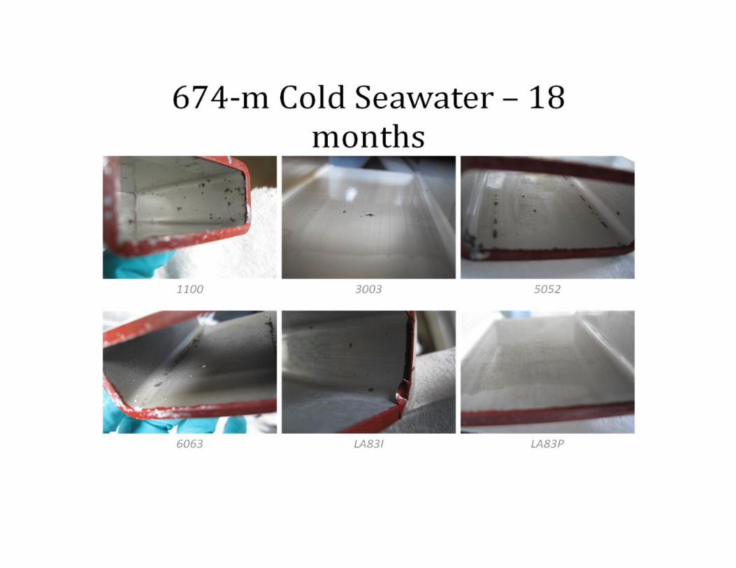
HOLLOW EXTRUSION (BOX) COUPONS
Box coupons are tested to evaluate the extrusion manufacturing process. Extruded channels can be used as the seawater passages in a heat exchanger (as in the Chart brazed aluminum heat exchanger). Extrusions of six different aluminum alloys are tested in three seawater sources using eight testing racks.
In Rack 5, the coupons were initially exposed to warm seawater for 50 days and then exposed to cold seawater. The Rack 5 experiment tests whether developing a thicker oxide film in warm seawater can provide greater corrosion resistance when moved to cold seawater. Initially corrosion rates were lower, but removal of 1 year samples revealed most Rack 5 samples had more pits than the cold seawater samples removed after the same exposure time.

Box Racks Rack
# Water source Date Exposed
Exposure Time (days)
1 915-m Cold 10/9/2009 6/9/2010
596 353
2 Surface Warm 12/8/2009 6/2/2010
536 360
3 Surface Warm 12/8/2009 6/2/2010
533 486
4 915-m Cold 12/11/2009 533
5 674-m Cold 674-m Cold Stagnant
1/27/2010* 6/2/10
536 Removed
6 674-m Cold 12/9/2009 6/2/2010
535 360
7 674-m Cold 12/11/2009 533
8 Surface Warm Stagnant 6/9/2010 Removed
Box coupons are evaluated using electrochemistry and weight analysis. New box beam coupons have been installed in the existing racks to replace samples that were removed for weight analysis. Box coupons have been removed for 3-, 6-, 9-, 12-, and 18-month weight analysis:
0
1
2
3
4
5
6
40 60 100 120 180 365 545
Sam
ples
Rem
oved
(per
allo
y)
Exposure Time [days]
915-m Cold 674-m Cold Warm Rack 5

Findings
Electrochemistry and Weight Analysis Results. General (uniform) corrosion rates are similar amongst the alloys and average to less than 20 mils over a 30 year period:
Table 1. Predicted metal loss over 30 year period from uniform corrosion
Predicted 30-year Metal Loss [mils] 40-CSW 55-CSW WSW
Allo
y 1100 13.2 7.6 16.4 3003 8.6 5.49 10.5 5052 7.5 5.7 6.5 6063 4.8 4.2 8.6 LA83I 6.1 13.3 9.6 LA83P 8.3 7.3 10.5
Visual Inspection Results. In warm seawater the 18-month samples had severe biofouling. Pits were observed in Alloy 1100 in warm seawater; however, small discolorations that are indicative of pits were present on the other alloys exposed to warm seawater. Pitting has been observed in all alloys in the one-year and 18 month samples exposed to the 674-m and 915-m cold seawater. Except for Alloy 1100, not all coupons had pits in cold seawater. In most coupons, only small pits were present. The presence of pits does not automatically exclude aluminum as a heat exchanger material. In aluminum, pits can self-passivate and material integrity is maintained. The rate of pit growth may also be low enough so that it provides an acceptable heat exchanger lifetime.
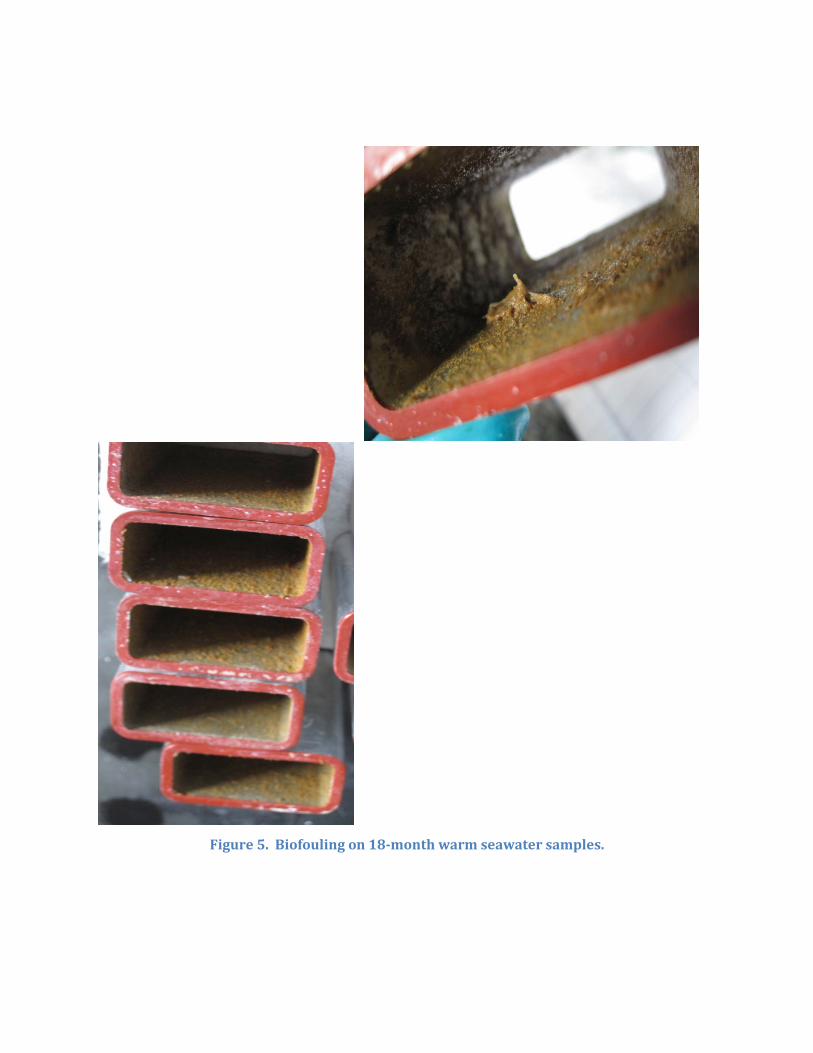
Figure 5. Biofouling on 18-month warm seawater samples.
Because general corrosion rates are low and comparable amongst the different alloys, alloy selection and the feasibility of an aluminum heat exchanger will be decided on the resistance to localized corrosion (pitting and defects).
Additional work is needed to develop quantitative analysis of pit growth and density. Options that we are exploring include ultrasonic depth measurements, laser profilometry, and image analysis.
FLAT COUPONS
Flat coupons are used to provide the flexibility to test different configurations (e.g., manufacturing techniques and surface finishes) of samples. Flat coupons were initially evaluated using electrochemistry and weight analysis. However, some flaws in the rack design invalidate these results. On many samples, the unexposed side of the coupon was corroded. This arose from inadequate sealing between the coupon and the gasket. The unexposed sides were painted to prevent crevice corrosion, however, either the paint did not adhere properly or defects were present in the coat.
The flat racks were modified with clear acrylic lids so visual observations of the exposed surface could be used to evaluate performance. The clear lids verified the issue of inadequate sealing against the gasket. Corrosion product buildup could be observed at the edge of most coupons. In addition, non-uniform flow patterns resulted in trapped bubbles at coupon edges and are also a source of localized corrosion.
The FSW flat rack was modified to incorporate a small gasket and to offset the back of the coupon from the rack base. Most of the coupon would be exposed to seawater, although the back side was still painted.
The use of PEM mounts allowed electrical contact with the coupon for electrochemistry tests without creating a galvanic cell when exposed to seawater. However, the PEM mount hole was readily observed on the to-be-exposed surface of the 6063 bare, electropolished, and FSW samples. The installation of the PEM mount is suspected to have cold worked the material that may impact the corrosion performance of the samples.
Corrosion particles in one area of a sample may affect the rest of the sample. Corrosion particles are also suspected to affect downstream samples. Future testing will use larger samples to minimize edge/crevice/gasket effects.
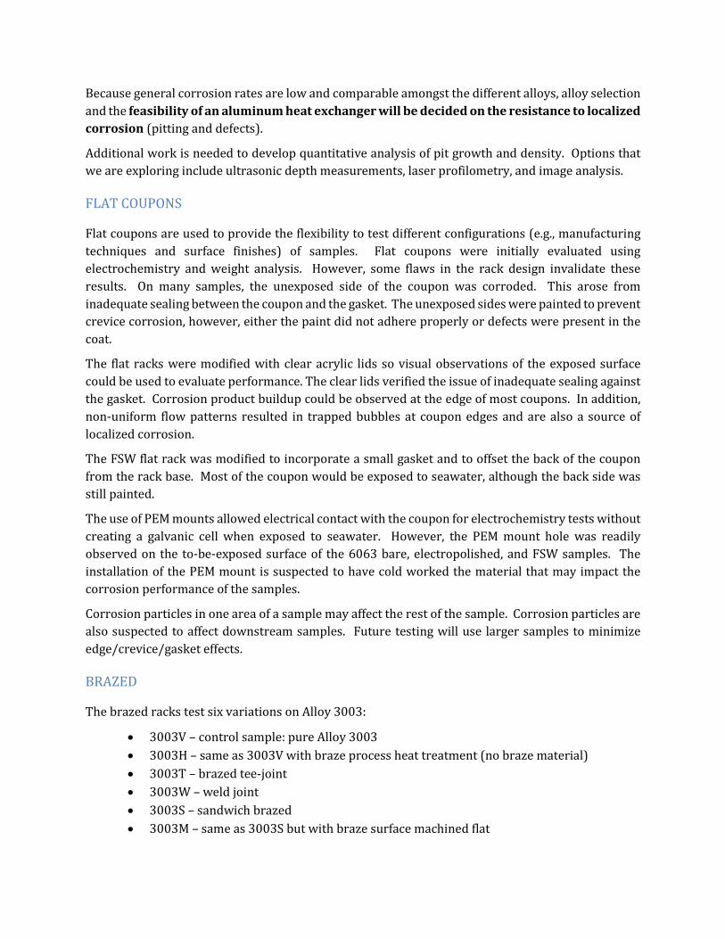
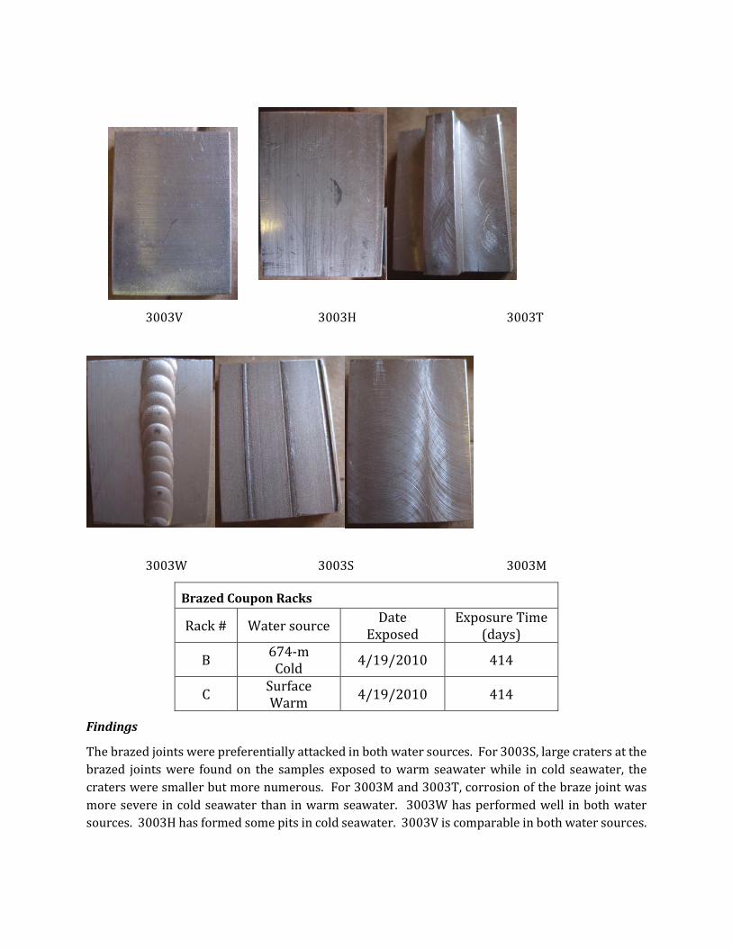
BRAZED
The brazed racks test six variations on Alloy 3003:
• 3003V – control sample: pure Alloy 3003 • 3003H – same as 3003V with braze process heat treatment (no braze material) • 3003T – brazed tee-joint • 3003W – weld joint • 3003S – sandwich brazed • 3003M – same as 3003S but with braze surface machined flat
3003V 3003H 3003T
3003W 3003S 3003M
Brazed Coupon Racks
Rack # Water source Date Exposed
Exposure Time (days)
B 674-m Cold 4/19/2010 414
C Surface Warm 4/19/2010 414
Findings
The brazed joints were preferentially attacked in both water sources. For 3003S, large craters at the brazed joints were found on the samples exposed to warm seawater while in cold seawater, the craters were smaller but more numerous. For 3003M and 3003T, corrosion of the braze joint was more severe in cold seawater than in warm seawater. 3003W has performed well in both water sources. 3003H has formed some pits in cold seawater. 3003V is comparable in both water sources.

Severely corroding coupons have been removed from the racks. Originally, electrochemistry was used to provide in-situ evaluation of the samples’ performance. However, the presence of pitting and corrosion on the back side of the coupon invalidate electrochemistry (and weight analysis) results. The racks have been refitted with a clear acrylic lid and visual analysis will replace electrochemistry to evaluate performance.
ELECTROPOLISHED AND BARE
Electropolished samples of Alloys 3003, 5052, and 6063 along with untreated samples of Alloy 3003, 5052, and 6063 are being tested in 2 flat coupon racks.
Flat Coupon Racks
Rack # Water source Date Exposed
Exposure Time (days)
D 674-m Cold 8/9/2010 302
E Surface Warm 8/9/2010 302
Findings
The electropolished (EP) samples performed poorly in cold seawater. The surfaces of the 3003 EP samples in cold seawater were evenly covered with pits. In 6063 EP samples, pit coverage was not even across the surface, but concentrated in the center of the coupon on the backside of where the PEM was mounted. The untreated 6063 samples also developed pits in this location; however, pitting was more severe in the EP samples. The 5052 EP samples had a few small pits.
3003EP 6063EP
The cold seawater rack was inspected about 2 months after installation. Most of the untreated 6063 samples had pits that corresponded to the PEM mount position. The pitted samples, along with the EP samples were removed and the rack was refitted with a clear acrylic lid. Currently, the remaining untreated 6063 samples continue to have corrosion product buildup on the surfaces. The untreated 3003 samples have begun to show dark spots indicative of pits. The untreated 5052 samples appear to be performing best although two samples have severe corrosion product buildup.

The warm seawater rack was also inspected about 2 months after installation. The samples appeared to be performing well so the rack was reinstalled without changes. The rack has not been disturbed and will be re-inspected in August 2011, after 1-yr of exposure.
FRICTION STIR WELDED
Friction stir welded (FSW) flat coupons are being tested in 2 flat racks with clear acrylic lids.
Clear Lid Flat Racks
Rack # Water source Date Exposed
Exposure Time (days)
F 674-m Cold 12/9/2010 180
G Surface Warm 12/9/2010 180
Findings
The cold seawater FSW coupons have developed dark spots that are likely pits. The warm seawater FSW coupons do not appear to have pits; however, the coupons are covered with biofouling (most likely caused by light exposure through the clear acrylic lid).
FSW in cold seawater FSW in warm seawater
VELOCITY COUPONS
Tubular coupons of Alloys 5086 and 6063 are being tested in 2 velocity racks.
Velocity Coupon Racks
Rack # Water source Date Exposed
Exposure Time (days)
Alpha 674-m Cold 9/14/2010 270

Beta Surface Warm 9/14/2010 270
In the velocity rack, part of the seawater flow is diverted at the exit of each column so that successive columns have a lower flow rate (and velocity). The flow rate was determined by recording the time to fill a 5-gallon bucket using the discharge of each column.
Findings
The last two columns in the velocity rack are suspected to be stagnant or empty.
Velocity racks were to be evaluated with electrochemistry and weight analysis. Electrochemistry results appear to be affected by the velocity of the seawater, i.e., for different seawater velocities, the results do not appear to be comparable. For the velocity racks, where the velocity is different for each column, weight analysis may be the best analytical tool.
Velocity coupons will be removed after one year and replaced a single coupon for each column, which reduces biased results caused by crevice corrosion at the gasket interface by eliminating gaskets except at the beginning and end of each column.
PLANNED TESTING
New testing racks have been designed and are being manufactured to test more representative samples: tubular friction stir weld and large plate coupons. A Chart testing rack is also being built. Based on the results from box coupon testing, future testing will focus on visual documentation of corrosion progress.
Post-removal laser profilometry and in-situ ultrasonic detection of wall thickness will also be evaluated for their effectiveness in quantifying localized corrosion.

V. Conclusion and Outlook Two heat exchangers (manufactured by Chart Industries and Lockheed Martin) have been developed specifically to address OTEC operating conditions and are ready for testing. The Chart brazed aluminum evaporator uses brazed aluminum fins in the ammonia channels and square extruded passages for the seawater channels. The fins enhance heat transfer and the extruded channels eliminate exposing brazed joints to the corrosive seawater environment. The Lockheed shell and tube condenser showcases the use of tubular friction stir welding – a new manufacturing technique – to join tubes to the tubesheet. The use of aluminum alloys and friction stir welding combine the desirable corrosion resistance of the alloy and manufacturing method, as well as a lowered cost of manufacturing.
These baseline heat exchangers have been installed and shakedown testing has been completed. Major improvements in instrumentation, data collection, and control software enable a wide range of testing conditions and relatively short transient time between testing points. Formal testing will commence after instrument calibration and continue for several months in order to capture how performance is affected by time-dependent processes such as oxide layer and biofoulant buildup.
The preliminary results of the corrosion testing program indicate localized corrosion will determine the viability of aluminum heat exchangers. New testing apparatuses and analysis methods will focus on quantifying localized corrosion so the different alloys can be compared. In parallel, new possibilities for materials, coatings, and preventative treatments (to address corrosion and biofouling) will be investigated.
The combined findings from heat exchanger performance testing and corrosion testing will be used to develop the next generation of OTEC heat exchangers.