Harvesting Waste Thermal Energy Using a Carbon-Nanotube ...€¦ · †Alan G. MacDiarmid NanoTech...
9
Harvesting Waste Thermal Energy Using a Carbon-Nanotube-Based Thermo- Electrochemical Cell Renchong Hu, † Baratunde A. Cola, § Nanda Haram, | Joseph N. Barisci, † Sergey Lee, †,¶ Stephanie Stoughton, † Gordon Wallace, ⊥ Chee Too, ⊥ Michael Thomas, ⊥ Adrian Gestos, ⊥ Marilou E. dela Cruz, ‡ John P. Ferraris, †,‡ Anvar A. Zakhidov, † and Ray H. Baughman* ,†,‡ † Alan G. MacDiarmid NanoTech Institute, ‡ Department of Chemistry, University of Texas at Dallas, Richardson, Texas 75083, § George W. Woodruff School of Mechanical Engineering, Georgia Institute of Technology, Atlanta, Georgia 30332, | Department of Engineering Sciences, Maharashtra Academy of Engineering, Alandi (D), Pune 412 105, India, and ⊥ Intelligent Polymer Research Institute ARC Centre of Excellence for Electromaterials Science, University of Wollongong, Northfields Avenue, Wollongong, NSW 2522, Australia ABSTRACT Low efficiencies and costly electrode materials have limited harvesting of thermal energy as electrical energy using thermo- electrochemical cells (or “thermocells”). We demonstrate thermocells, in practical configurations (from coin cells to cells that can be wrapped around exhaust pipes), that harvest low-grade thermal energy using relatively inexpensive carbon multiwalled nanotube (MWNT) electrodes. These electrodes provide high electrochemically accessible surface areas and fast redox-mediated electron transfer, which significantly enhances thermocell current generation capacity and overall efficiency. Thermocell efficiency is further improved by directly synthesizing MWNTs as vertical forests that reduce electrical and thermal resistance at electrode/substrate junctions. The efficiency of thermocells with MWNT electrodes is shown to be as high as 1.4% of Carnot efficiency, which is 3-fold higher than for previously demonstrated thermocells. With the cost of MWNTs decreasing, MWNT-based thermocells may become commercially viable for harvesting low-grade thermal energy. KEYWORDS Thermo-electrochemical cells, thermogalvanic cells, thermocells, carbon nanotubes, thermal energy harvesting, low-grade waste heat L ow-grade heat (temperature below 130 °C), from such sources as industrial waste streams, geothermal activ- ity, and solar heating, is projected to be a major sustainable energy source. 1,2 For many years the research community has focused on using solid-state thermoelectrics and Stirling engines to efficiently harvest low-grade heat as electrical energy. However, despite much progress over the past decades, current thermoelectric energy conversion technology is not very cost-effective and is constrained by physical and material limitations, 3 and Stirling engine tech- nology is disadvantaged by high initial cost and problems with long-term reliability. 4 Thermo-electrochemical cells (otherwise known as thermogalvanic cells or thermocells) that utilize the temperature dependence of electrochemical redox potentials (i.e., the Seebeck effect) to produce electri- cal power may become an attractive alternative for harvest- ing low-grade heat, given their simple design, direct thermal- to-electric energy conversion, continuous operation, low expected maintenance, and zero carbon emission. 5-7 The electrochemical Seebeck effect was first demon- strated over 100 years ago. 8,9 For a hypothetical redox system B S ne - + A, the Seebeck coefficient, S, can be expressed as where V is the electrode potential, T is temperature, n is the number of electrons involved in the reaction, F is Faraday’s constant, and ∆S B,A is the reaction entropy for the redox couple. 10,11 Thermocells using aqueous potassium ferrocya- nide/ferricyanide redox solution have been studied by many groups because this redox system reversibly exchanges one electron per iron atom and produces a large reaction en- tropy, yielding Seebeck coefficient (>1 mV/K) and high exchange current. 11-16 However, to obtain efficiencies of reasonable interest noble metals such as Pt are usually required as electrode materials in thermocells, and this restricts commercial viability. 14-18 Also, the best prior-art thermocells typically have efficiencies of ∼0.40% of Carnot efficiency (when efficiency is correctly evaluated, as dis- cussed below). 15,16 In fact, it was previously predicted that a power conversion efficiency of 1.2% of the Carnot ef- ficiency would be difficult to achieve. 15 * To whom correspondence should be addressed. E-mail: ray.baughman@ utdallas.edu. ¶ Current address: Plextronics, Inc. 2180 William Pitt Way, Pittsburgh, PA 15238. Received for review: 09/30/2009 Published on Web: 02/19/2010 S ) ∂ V ∂ T ) ∆S B,A nF (1) pubs.acs.org/NanoLett © 2010 American Chemical Society 838 DOI: 10.1021/nl903267n | Nano Lett. 2010, 10, 838–846
Transcript of Harvesting Waste Thermal Energy Using a Carbon-Nanotube ...€¦ · †Alan G. MacDiarmid NanoTech...
Harvesting Waste Thermal Energy Using aCarbon-Nanotube-Based Thermo-Electrochemical CellRenchong Hu,† Baratunde A. Cola,§ Nanda Haram,| Joseph N. Barisci,† Sergey Lee,†,¶
Stephanie Stoughton,† Gordon Wallace,⊥ Chee Too,⊥ Michael Thomas,⊥ Adrian Gestos,⊥Marilou E. dela Cruz,‡ John P. Ferraris,†,‡ Anvar A. Zakhidov,† and Ray H. Baughman*,†,‡
†Alan G. MacDiarmid NanoTech Institute, ‡Department of Chemistry, University of Texas at Dallas,Richardson, Texas 75083, §George W. Woodruff School of Mechanical Engineering, Georgia Institute of Technology,Atlanta, Georgia 30332, |Department of Engineering Sciences, Maharashtra Academy of Engineering, Alandi (D),Pune 412 105, India, and ⊥ Intelligent Polymer Research Institute ARC Centre of Excellence for ElectromaterialsScience, University of Wollongong, Northfields Avenue, Wollongong, NSW 2522, Australia
ABSTRACT Low efficiencies and costly electrode materials have limited harvesting of thermal energy as electrical energy using thermo-electrochemical cells (or “thermocells”). We demonstrate thermocells, in practical configurations (from coin cells to cells that can bewrapped around exhaust pipes), that harvest low-grade thermal energy using relatively inexpensive carbon multiwalled nanotube(MWNT) electrodes. These electrodes provide high electrochemically accessible surface areas and fast redox-mediated electron transfer,which significantly enhances thermocell current generation capacity and overall efficiency. Thermocell efficiency is further improvedby directly synthesizing MWNTs as vertical forests that reduce electrical and thermal resistance at electrode/substrate junctions. Theefficiency of thermocells with MWNT electrodes is shown to be as high as 1.4% of Carnot efficiency, which is 3-fold higher than forpreviously demonstrated thermocells. With the cost of MWNTs decreasing, MWNT-based thermocells may become commerciallyviable for harvesting low-grade thermal energy.
KEYWORDS Thermo-electrochemical cells, thermogalvanic cells, thermocells, carbon nanotubes, thermal energy harvesting,low-grade waste heat
Low-grade heat (temperature below 130 °C), from suchsources as industrial waste streams, geothermal activ-ity, and solar heating, is projected to be a major
sustainable energy source.1,2 For many years the researchcommunity has focused on using solid-state thermoelectricsand Stirling engines to efficiently harvest low-grade heat aselectrical energy. However, despite much progress over thepast decades, current thermoelectric energy conversiontechnology is not very cost-effective and is constrained byphysical and material limitations,3 and Stirling engine tech-nology is disadvantaged by high initial cost and problemswith long-term reliability.4 Thermo-electrochemical cells(otherwise known as thermogalvanic cells or thermocells)that utilize the temperature dependence of electrochemicalredox potentials (i.e., the Seebeck effect) to produce electri-cal power may become an attractive alternative for harvest-ing low-grade heat, given their simple design, direct thermal-to-electric energy conversion, continuous operation, lowexpected maintenance, and zero carbon emission.5-7
The electrochemical Seebeck effect was first demon-strated over 100 years ago.8,9 For a hypothetical redoxsystem B S ne- + A, the Seebeck coefficient, S, can beexpressed as
where V is the electrode potential, T is temperature, n is thenumber of electrons involved in the reaction, F is Faraday’sconstant, and ∆SB,A is the reaction entropy for the redoxcouple.10,11 Thermocells using aqueous potassium ferrocya-nide/ferricyanide redox solution have been studied by manygroups because this redox system reversibly exchanges oneelectron per iron atom and produces a large reaction en-tropy, yielding Seebeck coefficient (>1 mV/K) and highexchange current.11-16 However, to obtain efficiencies ofreasonable interest noble metals such as Pt are usuallyrequired as electrode materials in thermocells, and thisrestricts commercial viability.14-18 Also, the best prior-artthermocells typically have efficiencies of ∼0.40% of Carnotefficiency (when efficiency is correctly evaluated, as dis-cussed below).15,16 In fact, it was previously predicted thata power conversion efficiency of 1.2% of the Carnot ef-ficiency would be difficult to achieve.15
* To whom correspondence should be addressed. E-mail: [email protected].¶ Current address: Plextronics, Inc. 2180 William Pitt Way, Pittsburgh, PA 15238.Received for review: 09/30/2009Published on Web: 02/19/2010
S ) ∂V∂T
)∆SB,A
nF(1)
pubs.acs.org/NanoLett
© 2010 American Chemical Society 838 DOI: 10.1021/nl903267n | Nano Lett. 2010, 10, 838–846
Carbon nanotubes (CNTs) have been of considerableinterest for electrochemical applications, due to their excep-tional electronic, mechanical, and chemical properties.19-24
Advanced electrodes that incorporate CNTs have beenshown to provide attractive performance for electrochemicalapplications (e.g., batteries, supercapacitors, and fuelcells25-32), due to their high surface area, ability to carrylarge current densities, and fast electron transfer kinetics.33-35
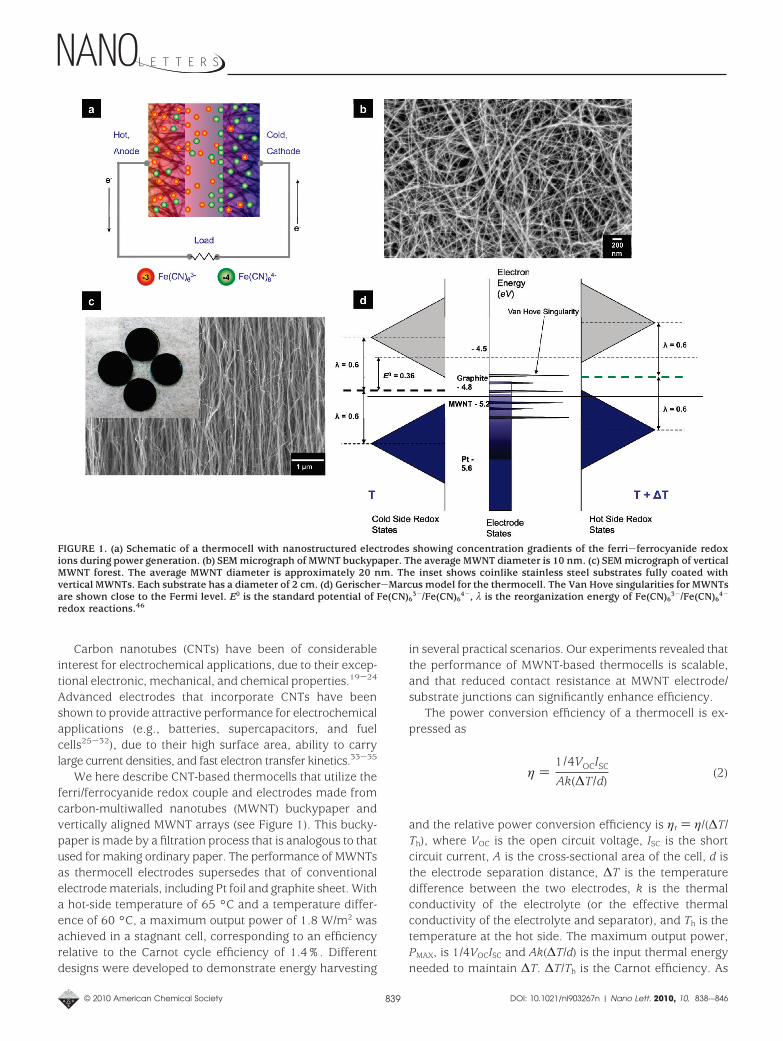
We here describe CNT-based thermocells that utilize theferri/ferrocyanide redox couple and electrodes made fromcarbon-multiwalled nanotubes (MWNT) buckypaper andvertically aligned MWNT arrays (see Figure 1). This bucky-paper is made by a filtration process that is analogous to thatused for making ordinary paper. The performance of MWNTsas thermocell electrodes supersedes that of conventionalelectrode materials, including Pt foil and graphite sheet. Witha hot-side temperature of 65 °C and a temperature differ-ence of 60 °C, a maximum output power of 1.8 W/m2 wasachieved in a stagnant cell, corresponding to an efficiencyrelative to the Carnot cycle efficiency of 1.4%. Differentdesigns were developed to demonstrate energy harvesting
in several practical scenarios. Our experiments revealed thatthe performance of MWNT-based thermocells is scalable,and that reduced contact resistance at MWNT electrode/substrate junctions can significantly enhance efficiency.
The power conversion efficiency of a thermocell is ex-pressed as
and the relative power conversion efficiency is ηr ) η/(∆T/Th), where VOC is the open circuit voltage, ISC is the shortcircuit current, A is the cross-sectional area of the cell, d isthe electrode separation distance, ∆T is the temperaturedifference between the two electrodes, k is the thermalconductivity of the electrolyte (or the effective thermalconductivity of the electrolyte and separator), and Th is thetemperature at the hot side. The maximum output power,PMAX, is 1/4VOCISC and Ak(∆T/d) is the input thermal energyneeded to maintain ∆T. ∆T/Th is the Carnot efficiency. As
FIGURE 1. (a) Schematic of a thermocell with nanostructured electrodes showing concentration gradients of the ferri-ferrocyanide redoxions during power generation. (b) SEM micrograph of MWNT buckypaper. The average MWNT diameter is 10 nm. (c) SEM micrograph of verticalMWNT forest. The average MWNT diameter is approximately 20 nm. The inset shows coinlike stainless steel substrates fully coated withvertical MWNTs. Each substrate has a diameter of 2 cm. (d) Gerischer-Marcus model for the thermocell. The Van Hove singularities for MWNTsare shown close to the Fermi level. E0 is the standard potential of Fe(CN)6
3-/Fe(CN)64-, λ is the reorganization energy of Fe(CN)6
3-/Fe(CN)64-
redox reactions.46
η )1/4VOCISC
Ak(∆T/d)(2)
© 2010 American Chemical Society 839 DOI: 10.1021/nl903267n | Nano Lett. 2010, 10, 838-–846
previously described, erroneous assumptions have beenoften made in evaluating energy conversion efficiencies.15
Efficiencies are also overestimated if the A in eq 1 is takenas the cross-sectional area of an electrode, and the effectivearea for ionic conduction and heat flow is much larger dueto a larger cross-sectional area of the cell.
The efficiency of the thermocell can be more fundamen-tally expressed by combining eq 1 and eq 2 to give
where jSC ()ISC/A) is the short circuit current density and RT
()d/k) is the thermal resistance of the cell. The ferri/ferro-cyanide redox couple, where n ) 1, is known to produce arelatively high reaction entropy,36 so we here focus onincreasing the parameters that critically limit thermocellefficiency, jSC and RT. The intrinsically large surface area ofMWNTs and fast electron transfer between MWNT elec-trodes and electrolyte directly enhance jSC.37-40 Thermalconduction losses are mitigated (i.e., RT is increased) usingtwo primary approaches that also enhance jSC, (1) we tookadvantage of the highly porous three-dimensional structureof MWNT buckypaper by using scroll-like electrodes, whichare commonly used in batteries and capacitors, to reducecross-sectional area normal to the direction of heat flowwhile allowing a high degree of electrolyte exposure to theelectrode surface for redox reactions to occur, and (2) wedirectly synthesized vertically aligned MWNT arrays (i.e.,nanotube forests) to establish electrodes that are in goodthermal and electrical contact with the thermocell pack-aging.41,42
The MWNT buckypaper was prepared according to pro-cedures described in previous work.43,44 The MWNTs are ofhigh purity (containing less than 1% catalyst) and hundredsof micrometers long, with diameters of ∼10 nm. The MWNTbuckypaper is typically ∼35 µm thick and has an electricalconductivity of 100 S/cm44 and an internal surface area of278 m2/g by the Brunauer-Emmett-Teller method. Figure1b shows a scanning electron micrograph (SEM) of theMWNT buckypaper. Cyclic voltammograms (CV) show quasi-reversible electron transfer reactions between MWNT buck-ypaper electrodes and Fe(CN)6
3-/4- in aqueous electrolyte.The MWNT buckypaper also shows three times highercharging current density during CV scans than the samephysical area Pt foil.
The electrical energy output of thermal electrochemicalcells can be optimized by ensuring that the temperature dropis predominantly between the electrodes, rather than be-tween the heat source and heat sink and the correspondingproximate electrodes. To reduce temperature drop fromthermal contact resistance for thermal cells based on con-ventional coin cell battery containers, MWNT forests weredirectly synthesized on the internal stainless steel electrode
surfaces of these coin cells. The MWNT forests were grownusing a trilayer catalyst (30 nm Ti, 10 nm Al, and 2 nm Fe),plasma-enhanced CVD, and previously reported processconditions.41 The MWNT forests were approximately 100µm tall. Vertical alignment of MWNTs and good coverage ofMWNTs on the surfaces of the packaging substrates isillustrated in Figure 1c. The thermal resistance at MWNTforest/substrate junctions was measured in previous workto be less than 0.01 cm2K/W, and the resistance of a solderjoint, the buckypaper electrodes are effectively soldered tothe packaging substrates in the coin cell configuration, is5-fold higher than this value.41 The electrolyte used for allthermocells in this work was 0.4 M K3Fe(CN)6/K4Fe(CN)6
aqueous solution, as this was demonstrated to be theoptimum redox couple concentration.
The performance of MWNT buckypaper, Pt foil (Sigma-Aldrich Co.), and graphite sheet (98% graphite, GrafTech,Inc.) electrodes were directly compared using a U-shapedelectrochemical cell. The hot side temperature was a con-stant 65 °C while the cold side temperature was 5 °C, thetwo electrodes were 5.0 cm apart, and each electrode sheetwas 1.0 cm × 0.5 cm. Conductive Ag paste was used topromote good electrical contact between buckypaper elec-trodes and Pt wire leads. The contacts were then coveredby insulating paint to prevent possible artifacts due tointeraction between the Ag paste and the electrolyte. Everydata point of VOC and ISC was acquired after allowing suf-ficient time for the values to stabilize. Similar Seebeckcoefficients of 1.4 mV/K were measured for all the electrodematerials, which is expected because the Seebeck coefficientis governed by the thermodynamics of the redox couple, notthe electrode material, as shown in eq 1.
The jSC and power (PMAX) generated by the MWNT bucky-paper electrodes for an optimized electrical load were thehighest among the tested electrode materials, 64.6 A/m2 and1.36 W/m2, respectively. The normalized current density, jSC/∆T, was 1.08 A/(m2K) and the normalized area powerdensity, PMAX/∆T2, was 3.8 × 10⁻⁴ W/(m2K2). The Pt elec-trodes generated a jSC of 48.4 A/m2 and a PMAX of 1.02 W/m2,corresponding to a jSC/∆T of 0.81 A/(m2K) and a PMAX /∆T2
of 2.8 × 10⁻⁴ W/(m2K2). The graphite sheet electrodesgenerated a jSC of 36.6 A/m2 and a PMAX of 0.76 W/m2,corresponding to a jSC/∆T of 0.61 A/(m2K) and a PMAX/∆T2 of2.1 × 10-4 W/(m2K2). The MWNT buckypaper electrodesthus produced 33 and 77% higher jSC/∆T than Pt andgraphite sheet electrodes, respectively. Previous work re-ported jSC/∆T ) 0.5 A/(m2K) and PMAX/∆T2 ) 2.0 × 10⁻⁴
W/(m2K2) using Pt electrodes with the same interelectrodedistance and only one side of each electrode exposed toelectrolyte.16 When we blocked one side of the anode andcathode with Scotch tape, jSC/∆T decreased 26% for theMWNT electrodes and decreased 28% for the Pt electrodes,which brings the present jSC/∆T for Pt electrodes into closeagreement with this previous work.
η )1/4∆SB,A jSCRT
nF(3)
© 2010 American Chemical Society 840 DOI: 10.1021/nl903267n | Nano Lett. 2010, 10, 838-–846
Upon reaching equilibrium, jSC in the Nernst-Plank equa-tion consists of diffusion current density jd ) FΣ(znDnDCn/Dx)and migration current density jm ) F2/RT(DV/Dx)Σ(zn
2DnCn),where zn is the charge, Dn is the diffusion coefficient, Cn isthe ion concentration, R is the gas constant, and x is thedistance from one electrode to the point of interest betweenthe two electrodes (the other parameters are the same asdefined above). Here jm is similar in all cases because thepotential differences across the electrodes are similar giventhe same ∆T. Therefore, jd, or more specifically the concen-tration gradient, DCn/Dx, must be different for the Pt, MWNT,and graphite electrodes studied here. One reason for therelatively large jSC (or jd) generated by MWNT electrodes isthe large number of redox reaction sites established by thehigh internal surface area of such electrodes. This surfacearea (or concentration gradient) advantage is likely the causeof MWNT electrodes producing higher current densities thanPt foil electrodes because the kinetics of the two materialsappears to be similar within the resolution of our experi-ments (see Figure S1 of Supporting Information). However,high-surface-area activated carbon fabric (Spectracarb 2225from Engineered Fibers Technology, LLC with an internalsurface area of 2500 m2/g) yielded a low jSC/∆T of 0.05A/(m2K) (evaluated using geometric area) when tested in theU-shaped cell, which implies that surface area enhancementsalone are not sufficient to generate large jSC. The compari-sons of the cyclic voltammetry (CV) scans for MWNT andgraphite sheets in Figure S1 of Supporting Informationclearly indicate slower electron transfer on graphite elec-trodes. It has been suggested that electron transfer at the
MWNT/electrolyte interface is enhanced as a result of fastkinetics.39 The improved kinetics over other carbon materi-als such as graphite sheet is likely the result of the quasi-one-dimensional crystalline structure of MWNTs and theirresulting highly localized electron density of states near theFermi level (i.e., Van Hove singularities).45 The Gerischer-Marcus model in Figure 1d illustrates this kinetic effect.
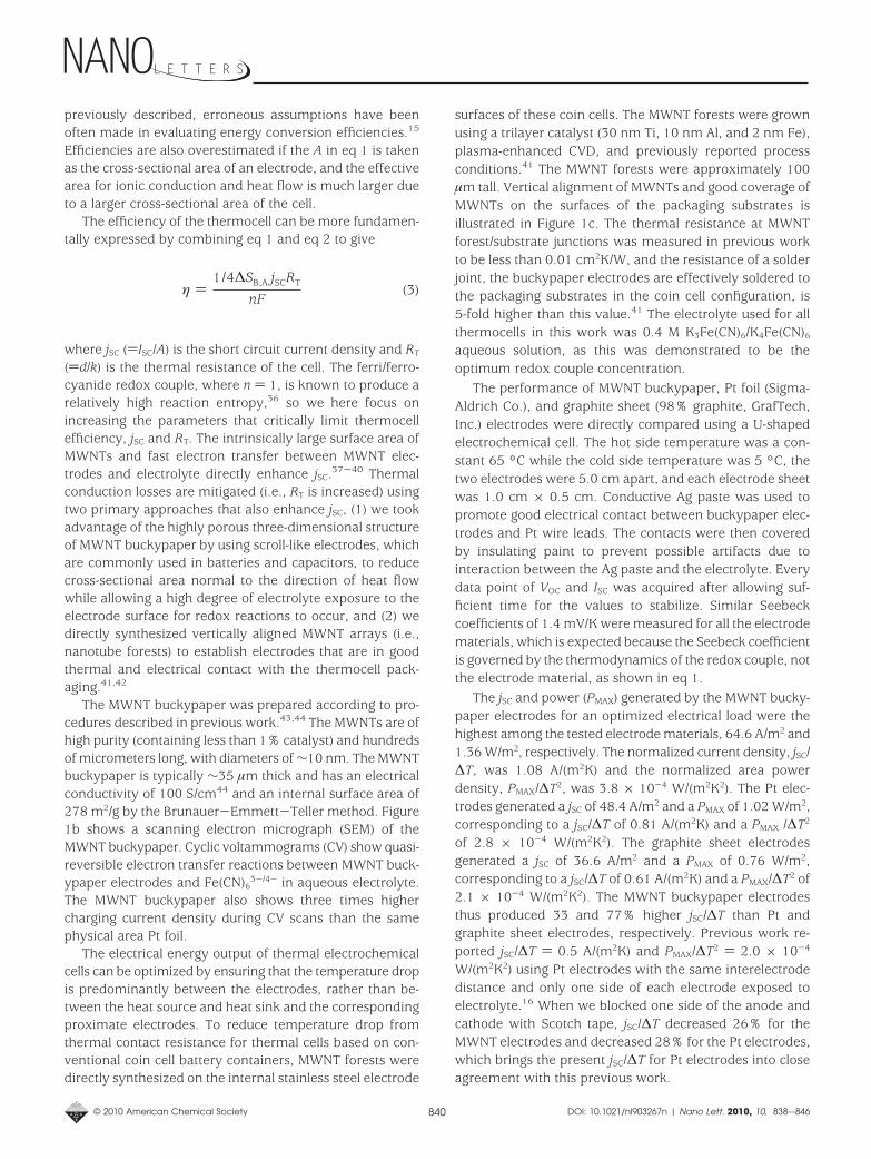
The Teflon cell shown in Figure 2a was used to evaluateperformance scaling with ∆T. The distance between twoequivalent size MWNT buckypaper electrodes was set at 2.6cm. The hot side was maintained at 70 °C using a resistiveheater connected to a temperature controller and the coldside temperature was adjusted by circulating coolant froma thermostat bath. As shown in Figure 2b, both VOC and jSC
increase linearly with ∆T, indicating the cell operates withina linear region. Variation of external load resistance resultedin linear variation of cell current on the voltage drop acrossthe load resistor, so output power was optimized wheneffective internal cell resistance equaled the external loadresistance. The cell in Figure 2a was also used to test thefeasibility of making larger MWNT-based thermocell devices(these tests were conducted with ∆T fixed). As shown inFigure 2c, increasing the electrode area from 0.4 to 1.2 cm2
increased the short circuit current from 0.8 to 2.7 mA andincreased the maximum power output from 16 to 55 µW.For the given range of electrode sizes, a linear relationshipbetween thermocell performance and electrode area isclearly shown, indicating scalability toward larger devices.When the thickness of buckypaper electrodes with fixed areawas increased from 40 to 280 µm, jSC increased from 47 to
FIGURE 2. (a) The Teflon cell with adjustable interelectrode distance. The cell consists of a HOTWATT heater, a Cu rod sealed in Teflon tapewith cold liquid circulating inside, a glass frit separator, and two OMEGA K-type thermocouples wrapped with Teflon tape. (b) VOC and jSC
versus temperature difference between electrodes. The distance between electrodes, d, was 2.6 cm. Each electrode was 1.8 mg and 1.5 cm× 0.8 cm × 30 µm. (c) ISC and PMAX versus MWNT electrode area with ∆T ) 47 °C, d ) 2.6 cm, MWNT buckypaper thickness 30 µm. (d) jSC andPMAX versus buckypaper electrode thickness with the area of each electrode fixed at 1.0 cm × 0.5 cm, ∆T ) 60 °C, d ) 2.6 cm.
© 2010 American Chemical Society 841 DOI: 10.1021/nl903267n | Nano Lett. 2010, 10, 838-–846
67 A/m2 and PMAX increased from 0.9 to 1.45 W/m2 (seeFigure 2d). The dependencies of jSC and PMAX on buckypapersheet thickness were nonlinear and a saturation thicknesswas evident during testing, likely because diffusion of theredox mediator through increasing thickness sheets be-comes a limiting factor. To demonstrate voltage and powerscaling, two identical thermocells (as shown in Figure S4 ofSupporting Information) were connected in series. The opencircuit voltage for the combined cells was 140 mV, which isequal to the sum of the open circuit voltages of the individualcells. The maximum output power of the combined cells was101.5 µW, which approximately equals the sum of themaximum output powers of the two cells when they areindividually operated (see Table S2 of Supporting Informa-tion).
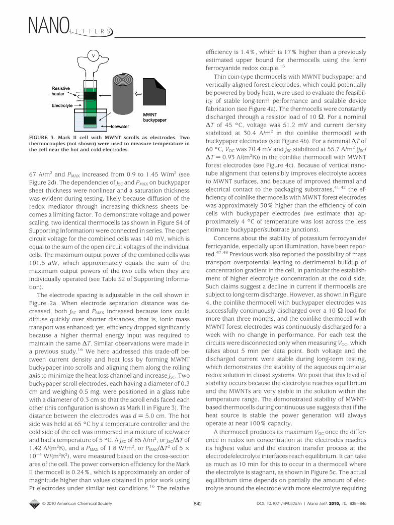
The electrode spacing is adjustable in the cell shown inFigure 2a. When electrode separation distance was de-creased, both jSC and PMAX increased because ions coulddiffuse quickly over shorter distances, that is, ionic masstransport was enhanced; yet, efficiency dropped significantlybecause a higher thermal energy input was required tomaintain the same ∆T. Similar observations were made ina previous study.16 We here addressed this trade-off be-tween current density and heat loss by forming MWNTbuckypaper into scrolls and aligning them along the rollingaxis to minimize the heat loss channel and increase jSC. Twobuckypaper scroll electrodes, each having a diameter of 0.3cm and weighing 0.5 mg, were positioned in a glass tubewith a diameter of 0.3 cm so that the scroll ends faced eachother (this configuration is shown as Mark II in Figure 3). Thedistance between the electrodes was d ) 5.0 cm. The hotside was held at 65 °C by a temperature controller and thecold side of the cell was immersed in a mixture of ice/waterand had a temperature of 5 °C. A jSC of 85 A/m2, or jSC/∆T of1.42 A/(m2K), and a PMAX of 1.8 W/m2, or PMAX/∆T2 of 5 ×10⁻⁴ W/(m2K2), were measured based on the cross-sectionarea of the cell. The power conversion efficiency for the MarkII thermocell is 0.24%, which is approximately an order ofmagnitude higher than values obtained in prior work usingPt electrodes under similar test conditions.16 The relative
efficiency is 1.4%, which is 17% higher than a previouslyestimated upper bound for thermocells using the ferri/ferrocyanide redox couple.15
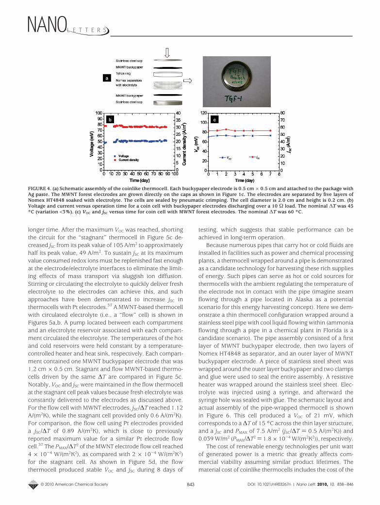
Thin coin-type thermocells with MWNT buckypaper andvertically aligned forest electrodes, which could potentiallybe powered by body heat, were used to evaluate the feasibil-ity of stable long-term performance and scalable devicefabrication (see Figure 4a). The thermocells were constantlydischarged through a resistor load of 10 Ω. For a nominal∆T of 45 °C, voltage was 51.2 mV and current densitystabilized at 30.4 A/m2 in the coinlike thermocell withbuckypaper electrodes (see Figure 4b). For a nominal ∆T of60 °C, VOC was 70.4 mV and jSC stabilized at 55.7 A/m2 (jSC/∆T ) 0.93 A/(m2K)) in the coinlike thermocell with MWNTforest electrodes (see Figure 4c). Because of vertical nano-tube alignment that ostensibly improves electrolyte accessto MWNT surfaces, and because of improved thermal andelectrical contact to the packaging substrates,41,42 the ef-ficiency of coinlike thermocells with MWNT forest electrodeswas approximately 30% higher than the efficiency of coincells with buckypaper electrodes (we estimate that ap-proximately 4 °C of temperature was lost across the lessintimate buckypaper/substrate junctions).
Concerns about the stability of potassium ferrocyanide/ferricyanide, especially upon illumination, have been repor-ted.47,48 Previous work also reported the possibility of masstransport overpotential leading to detrimental buildup ofconcentration gradient in the cell, in particular the establish-ment of higher electrolyte concentration at the cold side.Such claims suggest a decline in current if thermocells aresubject to long-term discharge. However, as shown in Figure4, the coinlike thermocell with buckypaper electrodes wassuccessfully continuously discharged over a 10 Ω load formore than three months, and the coinlike thermocell withMWNT forest electrodes was continuously discharged for aweek with no change in performance. For each test thecircuits were disconnected only when measuring VOC, whichtakes about 5 min per data point. Both voltage and thedischarged current were stable during long-term testing,which demonstrates the stability of the aqueous equimolarredox solution in closed systems. We posit that this level ofstability occurs because the electrolyte reaches equilibriumand the MWNTs are very stable in the solution within thetemperature range. The demonstrated stability of MWNT-based thermocells during continuous use suggests that if theheat source is stable the power generation will alwaysoperate at near 100% capacity.
A thermocell produces its maximum VOC once the differ-ence in redox ion concentration at the electrodes reachesits highest value and the electron transfer process at theelectrode/electrolyte interfaces reach equilibrium. It can takeas much as 10 min for this to occur in a thermocell wherethe electrolyte is stagnant, as shown in Figure 5c. The actualequilibrium time depends on partially the amount of elec-trolyte around the electrode with more electrolyte requiring
FIGURE 3. Mark II cell with MWNT scrolls as electrodes. Twothermocouples (not shown) were used to measure temperature inthe cell near the hot and cold electrodes.
© 2010 American Chemical Society 842 DOI: 10.1021/nl903267n | Nano Lett. 2010, 10, 838-–846
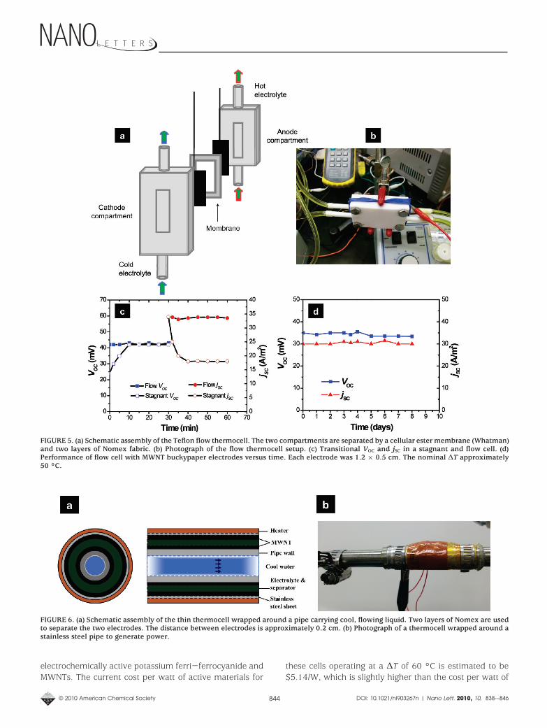
longer time. After the maximum VOC was reached, shortingthe circuit for the “stagnant” thermocell in Figure 5c de-creased jSC from its peak value of 105 A/m2 to approximatelyhalf its peak value, 49 A/m2. To sustain jSC at its maximumvalue consumed redox ions must be replenished fast enoughat the electrode/electrolyte interfaces to eliminate the limit-ing effects of mass transport via sluggish ion diffusion.Stirring or circulating the electrolyte to quickly deliver freshelectrolyte to the electrodes can achieve this, and suchapproaches have been demonstrated to increase jSC inthermocells with Pt electrodes.37 A MWNT-based thermocellwith circulated electrolyte (i.e., a “flow” cell) is shown inFigures 5a,b. A pump located between each compartmentand an electrolyte reservoir associated with each compart-ment circulated the electrolyte. The temperatures of the hotand cold reservoirs were held constant by a temperature-controlled heater and heat sink, respectively. Each compart-ment contained one MWNT buckypaper electrode that was1.2 cm × 0.5 cm. Stagnant and flow MWNT-based thermo-cells driven by the same ∆T are compared in Figure 5c.Notably, VOC and jSC were maintained in the flow thermocellat the stagnant cell peak values because fresh electrolyte wasconstantly delivered to the electrodes as discussed above.For the flow cell with MWNT electrodes, jSC/∆T reached 1.12A/(m2K), while the stagnant cell provided only 0.6 A/(m2K).For comparison, the flow cell using Pt electrodes provideda jSC/∆T of 0.89 A/(m2K), which is close to previouslyreported maximum value for a similar Pt electrode flowcell.37 The PMAX/∆T2 of the MWNT electrode flow cell reached4 × 10-4 W/(m2K2), as compared with 2 × 10⁻⁴ W/(m2K2)for the stagnant cell. As shown in Figure 5d, the flowthermocell produced stable VOC and jSC during 8 days of
testing, which suggests that stable performance can beachieved in long-term operation.
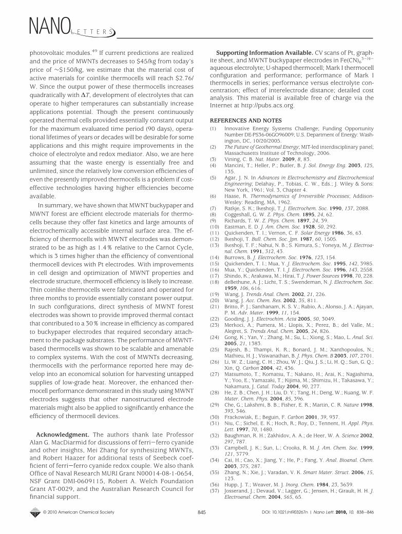
Because numerous pipes that carry hot or cold fluids areinstalled in facilities such as power and chemical processingplants, a thermocell wrapped around a pipe is demonstratedas a candidate technology for harvesting these rich suppliesof energy. Such pipes can serve as hot or cold sources forthermocells with the ambient regulating the temperature ofthe electrode not in contact with the pipe (imagine steamflowing through a pipe located in Alaska as a potentialscenario for this energy harvesting concept). Here we dem-onstrate a thin thermocell configuration wrapped around astainless steel pipe with cool liquid flowing within (ammoniaflowing through a pipe in a chemical plant in Florida is acandidate scenario). The pipe assembly consisted of a firstlayer of MWNT buckypaper electrode, then two layers ofNomex HT4848 as separator, and an outer layer of MWNTbuckypaper electrode. A piece of stainless steel sheet waswrapped around the outer layer buckypaper and two clampsand glue were used to seal the entire assembly. A resistiveheater was wrapped around the stainless steel sheet. Elec-trolyte was injected using a syringe, and afterward thesyringe hole was sealed with glue. The schematic layout andactual assembly of the pipe-wrapped thermocell is shownin Figure 6. This cell produced a VOC of 21 mV, whichcorresponds to a ∆T of 15 °C across the thin layer structure,and a jSC and PMAX of 7.5 A/m2 (jSC/∆T ) 0.5 A/(m2K)) and0.039 W/m2 (PMAX/∆T2 ) 1.8 × 10⁻⁴ W/(m2K2)), respectively.
The cost of renewable energy technologies per unit wattof generated power is a metric that greatly affects com-mercial viability assuming similar product lifetimes. Thematerial cost of coinlike thermocells includes the cost of the
FIGURE 4. (a) Schematic assembly of the coinlike thermocell. Each buckypaper electrode is 0.5 cm × 0.5 cm and attached to the package withAg paste. The MWNT forest electrodes are grown directly on the caps as shown in Figure 1c. The electrodes are separated by five layers ofNomex HT4848 soaked with electrolyte. The cells are sealed by pneumatic crimping. The cell diameter is 2.0 cm and height is 0.2 cm. (b)Voltage and current versus operation time for a coin cell with buckypaper electrodes discharging over a 10 Ω load. The nominal ∆T was 45°C (variation <3%). (c) VOC and jSC versus time for coin cell with MWNT forest electrodes. The nominal ∆T was 60 °C.
© 2010 American Chemical Society 843 DOI: 10.1021/nl903267n | Nano Lett. 2010, 10, 838-–846
electrochemically active potassium ferri-ferrocyanide andMWNTs. The current cost per watt of active materials for
these cells operating at a ∆T of 60 °C is estimated to be$5.14/W, which is slightly higher than the cost per watt of
FIGURE 5. (a) Schematic assembly of the Teflon flow thermocell. The two compartments are separated by a cellular ester membrane (Whatman)and two layers of Nomex fabric. (b) Photograph of the flow thermocell setup. (c) Transitional VOC and jSC in a stagnant and flow cell. (d)Performance of flow cell with MWNT buckypaper electrodes versus time. Each electrode was 1.2 × 0.5 cm. The nominal ∆T approximately50 °C.
FIGURE 6. (a) Schematic assembly of the thin thermocell wrapped around a pipe carrying cool, flowing liquid. Two layers of Nomex are usedto separate the two electrodes. The distance between electrodes is approximately 0.2 cm. (b) Photograph of a thermocell wrapped around astainless steel pipe to generate power.
© 2010 American Chemical Society 844 DOI: 10.1021/nl903267n | Nano Lett. 2010, 10, 838-–846
photovoltaic modules.49 If current predictions are realizedand the price of MWNTs decreases to $45/kg from today’sprice of ∼$150/kg, we estimate that the material cost ofactive materials for coinlike thermocells will reach $2.76/W. Since the output power of these thermocells increasesquadratically with ∆T, development of electrolytes that canoperate to higher temperatures can substantially increaseapplications potential. Though the present continuouslyoperated thermal cells provided essentially constant outputfor the maximum evaluated time period (90 days), opera-tional lifetimes of years or decades will be desirable for someapplications and this might require improvements in thechoice of electrolyte and redox mediator. Also, we are hereassuming that the waste energy is essentially free andunlimited, since the relatively low conversion efficiencies ofeven the presently improved thermocells is a problem if cost-effective technologies having higher efficiencies becomeavailable.
In summary, we have shown that MWNT buckypaper andMWNT forest are efficient electrode materials for thermo-cells because they offer fast kinetics and large amounts ofelectrochemically accessible internal surface area. The ef-ficiency of thermocells with MWNT electrodes was demon-strated to be as high as 1.4% relative to the Carnot Cycle,which is 3 times higher than the efficiency of conventionalthermocell devices with Pt electrodes. With improvementsin cell design and optimization of MWNT properties andelectrode structure, thermocell efficiency is likely to increase.Thin coinlike thermocells were fabricated and operated forthree months to provide essentially constant power output.In such configurations, direct synthesis of MWNT forestelectrodes was shown to provide improved thermal contactthat contributed to a 30% increase in efficiency as comparedto buckypaper electrodes that required secondary attach-ment to the package substrates. The performance of MWNT-based thermocells was shown to be scalable and amenableto complex systems. With the cost of MWNTs decreasing,thermocells with the performance reported here may de-velop into an economical solution for harvesting untappedsupplies of low-grade heat. Moreover, the enhanced ther-mocell performance demonstrated in this study using MWNTelectrodes suggests that other nanostructured electrodematerials might also be applied to significantly enhance theefficiency of thermocell devices.
Acknowledgment. The authors thank late ProfessorAlan G. MacDiarmid for discussions of ferri-ferro cyanideand other insights, Mei Zhang for synthesizing MWNTs,and Robert Haazer for additional tests of Seebeck coef-ficient of ferri-ferro cyanide redox couple. We also thankOffice of Naval Research MURI Grant N00014-08-1-0654,NSF Grant DMI-0609115, Robert A. Welch FoundationGrant AT-0029, and the Australian Research Council forfinancial support.
Supporting Information Available. CV scans of Pt, graph-ite sheet, and MWNT buckypaper electrodes in Fe(CN)6
3-/4-
aqueous electrolyte; U-shaped thermocell; Mark I thermocellconfiguration and performance; performance of Mark Ithermocells in series; performance versus electrolyte con-centration; effect of interelectrode distance; detailed costanalysis. This material is available free of charge via theInternet at http://pubs.acs.org.
REFERENCES AND NOTES(1) Innovative Energy Systems Challenge; Funding Opportunity
Number DE-PS36-06GO96009; U.S. Department of Energy: Wash-ington, DC, 10/20/2005.
(2) The Future of Geothermal Energy; MIT-led interdisciplinary panel;Massachusetts Institute of Technology, 2006.
(3) Vining, C. B. Nat. Mater. 2009, 8, 83.(4) Mancini, T.; Heller, P.; Butler, B. J. Sol. Energy Eng. 2003, 125,
135.(5) Agar, J. N. In Advances in Electrochemistry and Electrochemical
Engineering; Delahay, P., Tobias, C. W., Eds.; J. Wiley & Sons:New York, 1961; Vol. 3, Chapter 4.
(6) Haase, R. Thermodynamics of Irreversible Processes; Addison-Wesley: Reading, MA, 1962.
(7) Ratkje, S. K.; Ikeshoji, T. J. Electrochem. Soc. 1990, 137, 2088.(8) Coggeshall, G. W. Z. Phys. Chem. 1895, 24, 62.(9) Richards, T. W. Z. Phys. Chem. 1897, 24, 39.(10) Eastman, E. D. J. Am. Chem. Soc. 1928, 50, 292.(11) Quickenden, T. I.; Vernon, C. F. Solar Energy 1986, 36, 63.(12) Ikeshoji, T. Bull. Chem. Soc. Jpn. 1987, 60, 1505.(13) Ikeshoji, T. F.; Nahui, N. B.; S. Kimura, S.; Yoneya, M. J. Electroa-
nal. Chem. 1991, 312, 43.(14) Burrows, B. J. Electrochem. Soc. 1976, 123, 154.(15) Quickenden, T. I.; Mua, Y. J. Electrochem. Soc. 1995, 142, 3985.(16) Mua, Y.; Quickenden, T. I. J. Electrochem. Soc. 1996, 143, 2558.(17) Shindo, K.; Arakawa, M.; Hirai, T. J. Power Sources 1998, 70, 228.(18) deBethune, A. J.; Licht, T. S.; Swendeman, N. J. Electrochem. Soc.
1959, 106, 616.(19) Wang, J. Trends Anal. Chem. 2002, 21, 226.(20) Wang, J. Acc. Chem. Res. 2002, 35, 811.(21) Britto, P. J.; Santhanam, K. S. V.; Rubio, A.; Alonso, J. A.; Ajayan,
P. M. Adv. Mater. 1999, 11, 154.(22) Gooding, J. J. Electrochim. Acta 2005, 50, 3049.(23) Merkoci, A.; Pumera, M.; Llopis, X.; Perez, B.; del Valle, M.;
Alegret, S. Trends Anal. Chem. 2005, 24, 826.(24) Gong, K.; Yan, Y.; Zhang, M.; Su, L.; Xiong, S.; Mao, L. Anal. Sci.
2005, 21, 1383.(25) Rajesh, B.; Thampi, K. R.; Bonard, J. M.; Xanthopoulos, N.;
Mathieu, H. J.; Viswanathan, B. J. Phys. Chem. B 2003, 107, 2701.(26) Li, W. Z.; Liang, C. H.; Zhou, W. J.; Qiu, J. S.; Li, H. Q.; Sun, G. Q.;
Xin, Q. Carbon 2004, 42, 436.(27) Matsumoto, T.; Komatsu, T.; Nakano, H.; Arai, K.; Nagashima,
Y.; Yoo, E.; Yamazaki, T.; Kijima, M.; Shimizu, H.; Takasawa, Y.;Nakamura, J. Catal. Today 2004, 90, 277.
(28) He, Z. B.; Chen, J. H.; Liu, D. Y.; Tang, H.; Deng, W.; Kuang, W. F.Mater. Chem. Phys. 2004, 85, 396.
(29) Che, G.; Lakshmi, B. B.; Fisher, E. R.; Martin, C. R. Nature 1998,393, 346.
(30) Frackowiak, E.; Beguin, F. Carbon 2001, 39, 937.(31) Niu, C.; Sichel, E. K.; Hoch, R.; Roy, D.; Tennent, H. Appl. Phys.
Lett. 1997, 70, 1480.(32) Baughman, R. H.; Zakhidov, A. A.; de Heer, W. A. Science 2002,
297, 787.(33) Campbell, J. K.; Sun, L.; Crooks, R. M. J. Am. Chem. Soc. 1999,
121, 3779.(34) Cai, H.; Cao, X.; Jiang, Y.; He, P.; Fang, Y. Anal. Bioanal. Chem.
2003, 375, 287.(35) Zhang, N.; Xie, J.; Varadan, V. K. Smart Mater. Struct. 2006, 15,
123.(36) Hupp, J. T.; Weaver, M. J. Inorg. Chem. 1984, 23, 3639.(37) Josserand, J.; Devaud, V.; Lagger, G.; Jensen, H.; Girault, H. H. J.
Electroanal. Chem. 2004, 565, 65.
© 2010 American Chemical Society 845 DOI: 10.1021/nl903267n | Nano Lett. 2010, 10, 838-–846
(38) Baughman, R. H.; Cui, C.; Zakhidov, A. A.; Iqbal, Z.; Barisci,J. N.; Spinks, G. M.; Wallace, G. G.; Mazzoldi, A.; De Rossi, D.;Rinzler, A. G.; Jaschinski, O.; Roth, S.; Kertesz, M. Science 1999,284, 1340.
(39) Nugent, J. M.; Santhanam, K. S. V.; Rubio, A.; Ajayan, P. M. NanoLett. 2001, 1, 87.
(40) Andrews, R.; Jacques, D.; Qian, D.; Rantell, T. Acc. Chem. Res.2002, 35, 1008.
(41) Cola, B. A.; Xu, J.; Cheng, C.; Xu, X.; Hu, H.; Fisher, T. S. J. Appl.Phys. 2007, 101, No. 054313.
(42) Park, M.; Cola, B. A.; Siegmund, T.; Xu, J.; Maschmann, M. R.;Fisher, T. S.; Kim, H. Nanotechnology 2006, 17, 2294.
(43) Zhang, M.; Atkinson, K. R.; Baughman, R. H. Science 2004, 306,1358.
(44) Hall, L. J.; Coluci, V. R.; Galvao, D. S.; Kozlov, M. E.; Zhang, M.;Dantas, S. O.; Baughman, R. H. Science 2008, 320, 504.
(45) Schonenberger, C.; Bachtold, A.; Strunk, C.; Salvetat, J.-P.; Forro,L. Appl. Phys. A: Mater. Sci. Process. 1999, 69, 283.
(46) Morisaki, H.; Ono, H.; Yazawa, K. J. Electrochem. Soc. 1989, 136,1710.
(47) MacDiarmid, A. G.; Hall, N. F. J. Am. Chem. Soc. 1953, 75, 5204.(48) MacDiarmid, A. G.; Hall, N. F. J. Am. Chem. Soc. 1954, 76, 4222.(49) As of Dec. 29, 2009, the solar module price in the United States
market is $4.31 per Watt of peak power according to http://solarbuzz.com/moduleprices.htm.
© 2010 American Chemical Society 846 DOI: 10.1021/nl903267n | Nano Lett. 2010, 10, 838-–846