Hardware Setup and Operation - Milwaukee Makerspace · PDF fileHardware Setup and Operation...
40
FULL SPECTRUM LASER LLC V0.85 40W Hobby CO2 Laser Engraver Setup and Installation Guide HardwareSetupand Operation Volume 1
Transcript of Hardware Setup and Operation - Milwaukee Makerspace · PDF fileHardware Setup and Operation...

FULL SPECTRUM LASER LLC V0.85
40W Hobby CO2 Laser Engraver Setup and Installation Guide
Hardware Setup and Operation
Volume
1
S E T U P A N D I N S T A L L A T I O N G U I D E
Hardware Setup and Operation
2010 Full Spectrum Laser LLC
7310 Smoke Ranch Road • Suite D
Las Vegas, NV 89128
Phone 702.482.8594 • Fax 650.215.9917
www.fullspectrumlaser.com

Table of Contents Getting Started ....................................................................................................................... 1
Unpacking instructions: ........................................................................................................ 1
Box Contents: ......................................................................................................................... 2
A Brief Tour ........................................................................................................................... 3
Main Assembly ....................................................................................................................... 3
Rear Compartment ................................................................................................................ 4
Side Panel ................................................................................................................................ 5
Control Panel .......................................................................................................................... 6
Laser Head .............................................................................................................................. 7
Safety Information ................................................................................................................. 8
Laser Safety ............................................................................................................................. 8
Electrical Safety ...................................................................................................................... 8
Fire Safety ................................................................................................................................ 9
Additional Safety Measures .................................................................................................. 9
H a rdwa re Se t up ............................................................................................................ 10
Water Pump .......................................................................................................................... 10
Exhaust Fan .......................................................................................................................... 11
Air Compressor (optional upgrade) .................................................................................. 12
Honeycomb Cutting Table ................................................................................................. 13
Typical Workbench Setup ................................................................................................... 14
Focusing Your Laser ........................................................................................................... 14
Aligning Your Laser ............................................................................................................. 18
Connecting the Water Pump .............................................................................................. 21
Adjusting the Z-Plate .......................................................................................................... 23
Adjusting the Belt Tension: X-Axis .................................................................................. 24
Removing the Lens .............................................................................................................. 27
Replacing the Laser Tube ................................................................................................... 27
RetinaEngrave USB Software installation ........................................................................ 32

G E T T I N G T O K N O W Y O U R L A S E R
1
Getting Started
Thank you for your recent purchase of your 4th generation Full
Spectrum Laser LLC Hobby Laser.It is our wish that this product adds
value to your business or hobby activities for years to come. Please
take time to read this manual in its entirety to safely use your laser to
its full potential.
Important: Please carefully read all the instructions before attempting to operate the laser.
Never operate or test the laser without the water pump running and water. Never
attempt to operate the laser with the lid open or attempt to override the magnetic lid
protection switch.
hese installation instructions available online:
http://fslaser.com/resources/software-manual-downloads.
Familiarize yourself with the major components of your new hobby laser before use.
Unpacking instructions:
1. Open the box and remove the documentation located between the packing material and box
flaps as well as the honeycomb table.
2. Remove packing material and inspect the unit for any damage during shipping. Open the
front lid and remove accessories within. Please open the back lid and inspect the laser tube
carefully for any shipping damage. Contact us immediately if there are any visible cracks.
3. Often we will ship the laser with a hose clamp on the right round rail which must be removed
before use.
Chapter
1
T

H O W T O O P E R A T E Y O U R L A S E R
2
Box Contents:
1. 40w Hobby Laser w/ Power Cord
2. Black Water Pump
3. White Exhaust Fan and blue 4" diameter hose (Located inside Electronics Bay on the right)
4. Silver Honeycomb Cutting Table
5. Air compressor (Optional but highly recommended)
6. RetinaEngrave USB card and mini USB cable
7. Brown cutting depth adjustment ruler
8. Set of keys that operates on/off switch, opens control panel compartment and rear laser tube
compartment.
H O W T O O P E R A T E Y O U R L A S E R
3
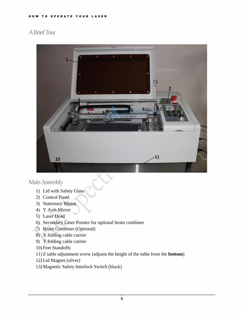
A Brief Tour
Main Assembly
1) Lid with Safety Glass
2) Control Panel
3) Stationary Mirror
4) Y Axis Mirror
5) Laser Head
6) Secondary Laser Pointer for optional beam combiner
7) Beam Combiner (Optional)
8) X folding cable carrier
9) Y folding cable carrier
10) Feet Standoffs
11) Z table adjustment screw (adjusts the height of the table from the bottom)
12) Lid Magnet (silver)
13) Magnetic Safety Interlock Switch (black)

H O W T O O P E R A T E Y O U R L A S E R
4
Rear Compartment
1. Laser tube
2. Laser Exhaust Fan mount holder
3. 110v Outlet for water pump (not recommend for use, plug pump directly to wall outlet)
4. 110v Outlet for air compressor (not recommend for use, plug directly to wall outlet)
5. 110v Outlet for fan (notrecommendedfor use, plug the fan directly to walloutlet)
6. Water inlet hose
7. Water outlet hose
8. Stationary mirror
9. Red high voltage laser power cable
10. Black high voltage laser power cable
11. Hose from Air compressor (push blue nub inward to allow insertion of tube)

H O W T O O P E R A T E Y O U R L A S E R
5
Side Panel
1. Power supply Exhaust Fan
2. RetinaEngrave USB access point
3. 110V 3-prong power plug with 6A fuse(maximum 660W)
4. Ground Point (attach this to the table top if using a metal table; otherwise do not attach to
anything).
H O W T O O P E R A T E Y O U R L A S E R
6
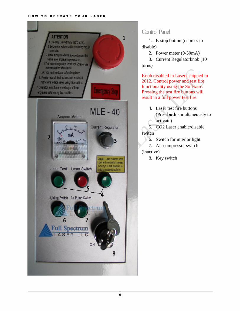
Control Panel
1. E-stop button (depress to
disable)
2. Power meter (0-30mA)
3. Current Regulatorknob (10
turns)
Knob disabled in Lasers shipped in
2012. Control power and test fire
functionality using the Software.
Pressing the test fire buttons will
result in a full power test fire.
4. Laser test fire buttons
(Pressboth simultaneously to
activate)
5. CO2 Laser enable/disable
switch
6. Switch for interior light
7. Air compressor switch
(inactive)
8. Key switch
H O W T O O P E R A T E Y O U R L A S E R
7
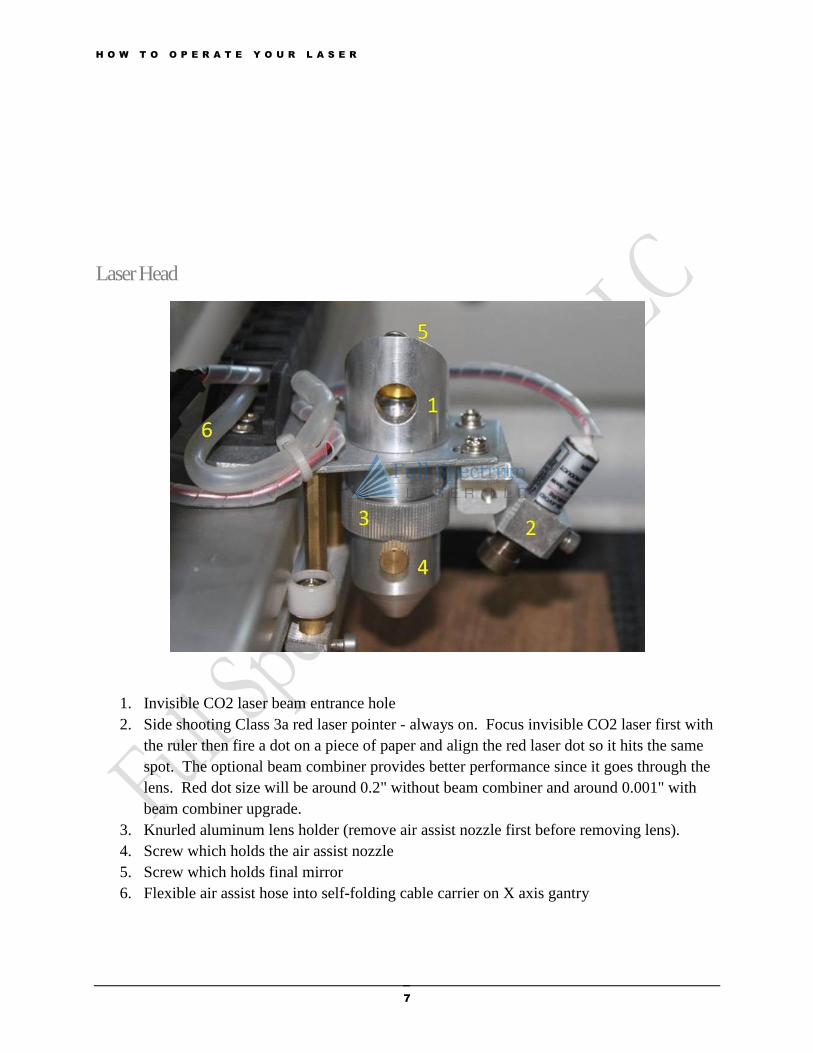
Laser Head
1. Invisible CO2 laser beam entrance hole
2. Side shooting Class 3a red laser pointer - always on. Focus invisible CO2 laser first with
the ruler then fire a dot on a piece of paper and align the red laser dot so it hits the same
spot. The optional beam combiner provides better performance since it goes through the
lens. Red dot size will be around 0.2" without beam combiner and around 0.001" with
beam combiner upgrade.
3. Knurled aluminum lens holder (remove air assist nozzle first before removing lens).
4. Screw which holds the air assist nozzle
5. Screw which holds final mirror
6. Flexible air assist hose into self-folding cable carrier on X axis gantry
H O W T O O P E R A T E Y O U R L A S E R
8
Safety Information
Please carefully read all the instructions before attempting to operate the laser. Never operate or test
the laser without the water pump. Never attempt to operate the laser with the lid open or attempt to
override the magnetic lid protection switch. Please inspect the laser tube carefully for any shipping
damage and contact us immediately if there are any visible cracks.
Laser Safety
Your Full Spectrum Laser LLC MLE-40 40w Hobby Laser is a Class 3a laser product, as defined
in
International Standard IEC 60825-1. The laser complies with 21 CFR 1040.10 and 1040.11,
theFederal Performance Standards for Light-Emitting Products, except for deviations
pursuant to Laser Notice No. 50, dated July 16, 2001. The Center for Devices and Radiological
Health, of the US FDA, issued Laser Notice No. 50 to permit manufacturers to classify and
manufacture their products in accordance with the International Standard.
The output of the CO2 engraving laser is fully contained in a Class 1 enclosure except for the
visible red laser pointer which is rated as a Class 3a laser product.
The laser cabinet has a magnetic safety interlock switch that deactivates the laser off if the door
is openedduring operation, and no special precautions are necessary to operate the highpower
laser safely. Never attempt to defeat the magnetic safety switch.
The operator of the 40w Hobby Laser should observe the following generalprecautions:
DO NOT disassemble the machine or remove any of its protective covers while the unit is
plugged in.
DO NOT attempt to defeat the door interlock.
DO NOT view directly into the beam of the Red Laser Diode Pointer.
Caution – Use of controls or adjustments or performance of procedures other than
those specified herein may result in hazardous laser radiation exposure.
Electrical Safety
The AC input power to the 40w Hobby Laser is potentially lethal and is fully contained within
the cabinet.
DO NOT open any of the machine’s access panels while the unit is plugged in. Opening a
panel may expose the operator to the unit’s AC input power.
DO NOT make or break any electrical connections to the system while the unit is turned on.
H O W T O O P E R A T E Y O U R L A S E R
9
Fire Safety
Laser cutting and engraving systems represent a significant fire hazard. Most engraving materials
are inherently combustible. While, the objective of most cutting and engraving operations is to
vaporize material without burning, it is easy to ignite a flame. Experience shows that vector
cutting with the laser has the most potential to create an open flame. Acrylic, in all its different
forms, has been shown to be especially flammable when vector cutting with the laser.
Please read the following warnings and recommendations and follow them closely at all times!
NEVERlet the laser system operate if it will be unattended.
ALWAYSkeepthe area around the machine clean and free of unnecessary clutter,
combustible materials, explosives, or volatile solvents such as acetone, alcohol, or gasoline.
ALWAYSkeep a properly maintained and inspected fire extinguisher on hand.
KEEP YOUR LASER SYSTEM CLEAN– Regularly remove the honeycomb grill to clean
any small pieces that have fallen through the grid.
Additional Safety Measures
NEVERoperate the machine without a properly operating vent to the outside!
NEVERengrave or cut any material containing chlorine or hydrogen gas such as PVC or vinyl.
Doing so will produce gasses that will corrode the interior of the laser and is not covered under
warranty.
NEVER operate your machine unattended. There is a significant risk of fire if the machine is set
improperly, or if the machine should experience a mechanical or electrical failure while
operating.
NEVERvector cut any material while the machine is unattended. Because vector cutting moves
relatively slowly compared to raster engraving, a tremendous amount of heat is applied to the
material being cut. This buildup of heat can cause significant fire risk and the machine should
always be monitored.
NEVERoperate with any of the covers or enclosures removed, and never modify the enclosure.
The laser beam is invisible!
H O W T O O P E R A T E Y O U R L A S E R
10
Hardware Setup
Although power outlets are supplied on the back of the Hobby Laser for theExhaust
Fan, water pump and air compressor, we recommend connecting these devices to a
power strip or circuit breaker separate from the laser. Always ensure these devices are
powered on before starting the Hobby Laser.
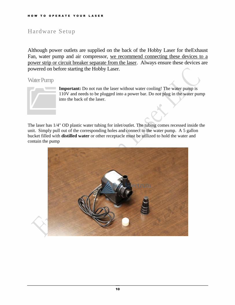
Water Pump
Important: Do not run the laser without water cooling! The water pump is
110V and needs to be plugged into a power bar. Do not plug in the water pump
into the back of the laser.
The laser has 1/4" OD plastic water tubing for inlet/outlet. The tubing comes recessed inside the
unit. Simply pull out of the corresponding holes and connect to the water pump. A 5 gallon
bucket filled with distilled water or other receptacle must be utilized to hold the water and
contain the pump
H O W T O O P E R A T E Y O U R L A S E R
11
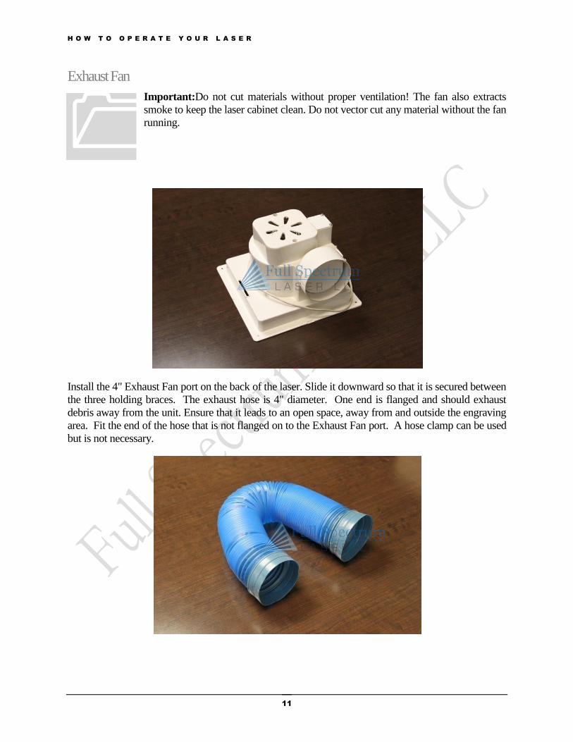
Exhaust Fan
Important:Do not cut materials without proper ventilation! The fan also extracts
smoke to keep the laser cabinet clean. Do not vector cut any material without the fan
running.
Install the 4" Exhaust Fan port on the back of the laser. Slide it downward so that it is secured between
the three holding braces. The exhaust hose is 4" diameter. One end is flanged and should exhaust
debris away from the unit. Ensure that it leads to an open space, away from and outside the engraving
area. Fit the end of the hose that is not flanged on to the Exhaust Fan port. A hose clamp can be used
but is not necessary.
H O W T O O P E R A T E Y O U R L A S E R
12
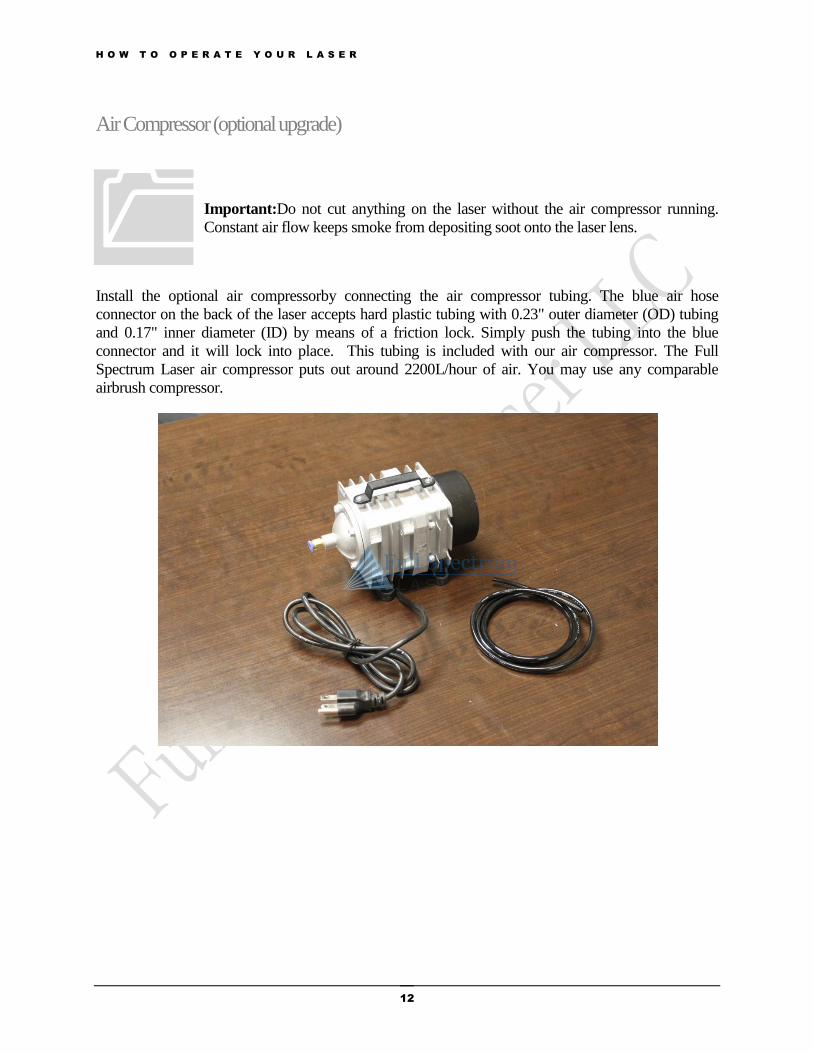
Air Compressor (optional upgrade)
Important:Do not cut anything on the laser without the air compressor running.
Constant air flow keeps smoke from depositing soot onto the laser lens.
Install the optional air compressorby connecting the air compressor tubing. The blue air hose
connector on the back of the laser accepts hard plastic tubing with 0.23" outer diameter (OD) tubing
and 0.17" inner diameter (ID) by means of a friction lock. Simply push the tubing into the blue
connector and it will lock into place. This tubing is included with our air compressor. The Full
Spectrum Laser air compressor puts out around 2200L/hour of air. You may use any comparable
airbrush compressor.
H O W T O O P E R A T E Y O U R L A S E R
13
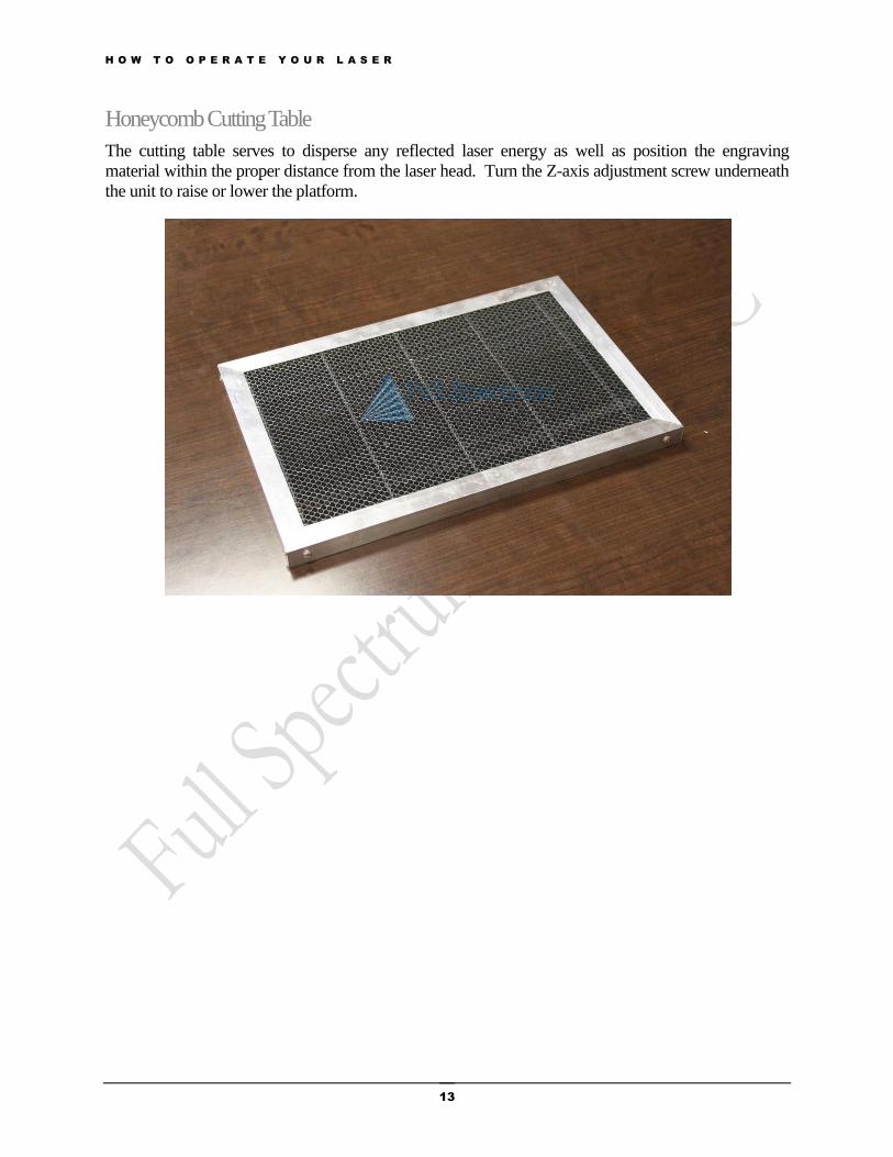
Honeycomb Cutting Table
The cutting table serves to disperse any reflected laser energy as well as position the engraving
material within the proper distance from the laser head. Turn the Z-axis adjustment screw underneath
the unit to raise or lower the platform.
H O W T O O P E R A T E Y O U R L A S E R
14
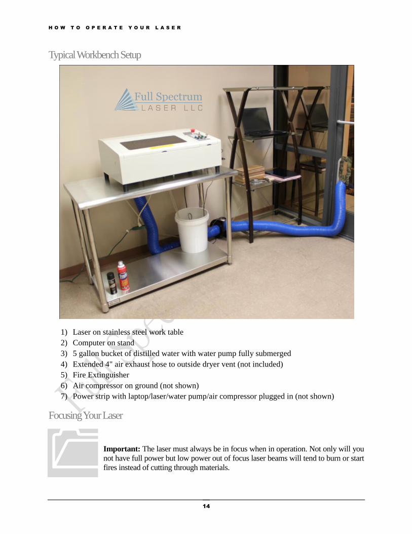
Typical Workbench Setup
1) Laser on stainless steel work table
2) Computer on stand
3) 5 gallon bucket of distilled water with water pump fully submerged
4) Extended 4" air exhaust hose to outside dryer vent (not included)
5) Fire Extinguisher
6) Air compressor on ground (not shown)
7) Power strip with laptop/laser/water pump/air compressor plugged in (not shown)
Focusing Your Laser
Important: The laser must always be in focus when in operation. Not only will you
not have full power but low power out of focus laser beams will tend to burn or start
fires instead of cutting through materials.
H O W T O O P E R A T E Y O U R L A S E R
15
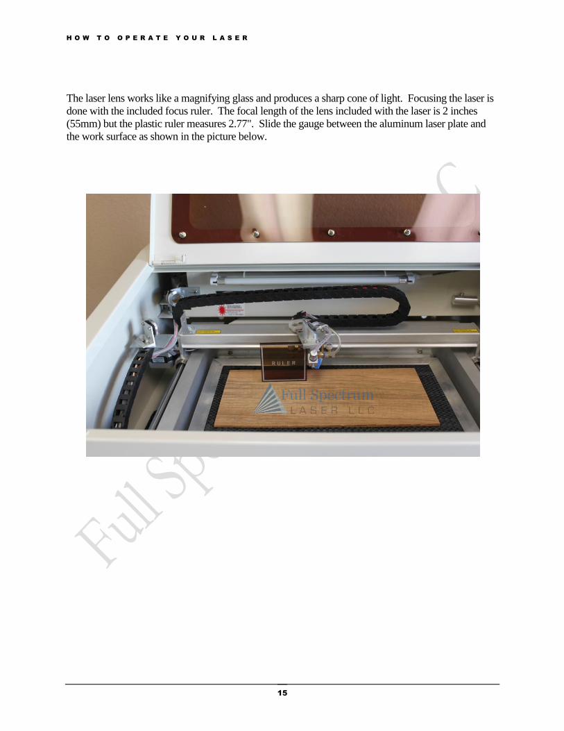
The laser lens works like a magnifying glass and produces a sharp cone of light. Focusing the laser is
done with the included focus ruler. The focal length of the lens included with the laser is 2 inches
(55mm) but the plastic ruler measures 2.77". Slide the gauge between the aluminum laser plate and
the work surface as shown in the picture below.

H O W T O O P E R A T E Y O U R L A S E R
16
Top of ruler contacts bottom of laser head plate (not attached to red pointer)
Rotate by hand to raise/lower Z-Table Optional acrylic wheel can be attached here.
H O W T O O P E R A T E Y O U R L A S E R
17
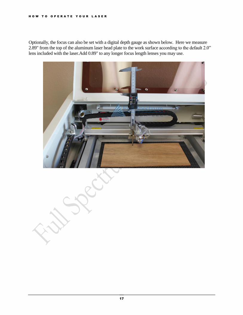
Optionally, the focus can also be set with a digital depth gauge as shown below. Here we measure
2.89" from the top of the aluminum laser head plate to the work surface according to the default 2.0”
lens included with the laser.Add 0.89" to any longer focus length lenses you may use.

H O W T O O P E R A T E Y O U R L A S E R
18
Aligning Your Laser
Please view our alignment video for detailed instructions, available at the following address:
http://fslaser.com/resources/software-manual-downloads
Often times when the laser does not produce an even burn over the entire workspace, the laser is out
of alignment. Usually this is characterized by uneven burning with the left side of the image darker
than the right side (see image below). If the laser is extremely far out of alignment, no spot through
the lens may appear at all. One can always verify the laser is working by placing a small piece of
paper near the stationary mirror (Mirror One in the rear next to the laser tube) and pressing both green
laser test switches. If the current meter is moving, the laser is working.
Your laser is carefully aligned at the factory but may come out of alignment during shipping or
unpacking. This procedure will explain to you how to align the laser for optimal cutting.
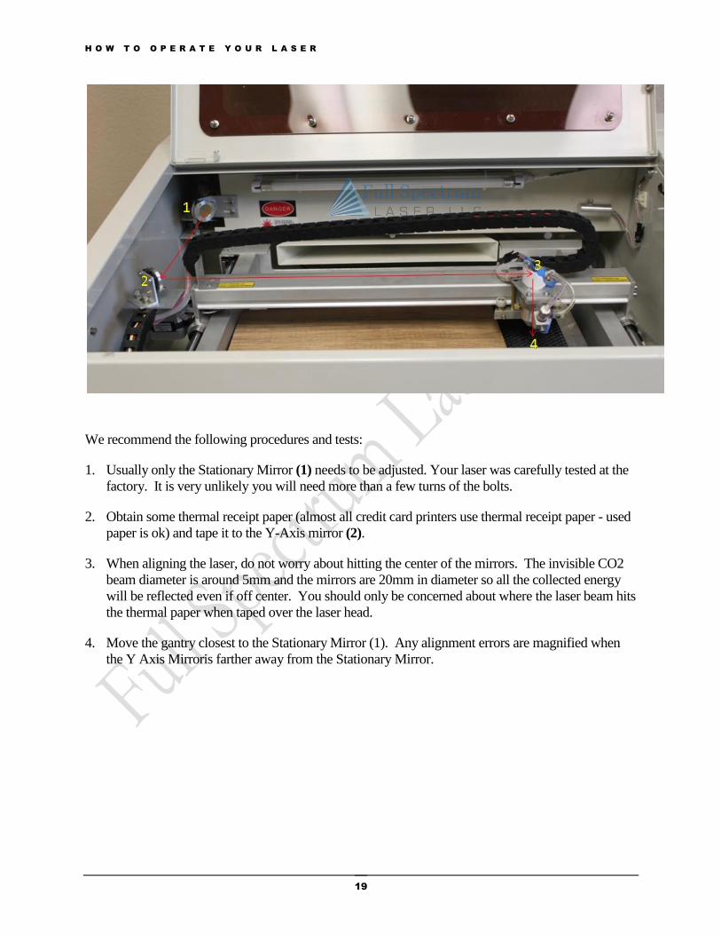
The laser path is shown below. The invisible beam bounces off the stationary mirror (not shown)
behind the optional beam combiner (normally not included). Then the beam passes through the beam
combiner (1) and bounces off the moving Y axis mirror (2). The beam proceeds to bounce off the
flying X axis mirror (3) down the laser tube and through the lens (4). If any of the mirrors is off by
even 0.1 degrees, the results will not be good.
H O W T O O P E R A T E Y O U R L A S E R
19
We recommend the following procedures and tests:
1. Usually only the Stationary Mirror (1) needs to be adjusted. Your laser was carefully tested at the
factory. It is very unlikely you will need more than a few turns of the bolts.
2. Obtain some thermal receipt paper (almost all credit card printers use thermal receipt paper - used
paper is ok) and tape it to the Y-Axis mirror (2).
3. When aligning the laser, do not worry about hitting the center of the mirrors. The invisible CO2
beam diameter is around 5mm and the mirrors are 20mm in diameter so all the collected energy
will be reflected even if off center. You should only be concerned about where the laser beam hits
the thermal paper when taped over the laser head.
4. Move the gantry closest to the Stationary Mirror (1). Any alignment errors are magnified when
the Y Axis Mirroris farther away from the Stationary Mirror.

H O W T O O P E R A T E Y O U R L A S E R
20
5. Fire the Test laser beam from the software after settings the test fire duration to 5ms.
6. Adjust the screws on the Y axis mirror in small increments. A quarter turn will put the laser out
of alignment. Tighten screws 1 and 2 to tilt the laser beam up. Tighten 2 to shift it right. Tighten
3 to shift it down. Tighten 1 to shift it left.
H O W T O O P E R A T E Y O U R L A S E R
21
7. Adjust the bolts so that the dark spot produced on the thermal paper areover the mirror.
8. Move the laser headdown about 2 inches. Now press the laser test buttons again and see where
the spot is. The further away you move the laser head the more amplified any angle alignment
errors in the laser beam will be. Adjust it until the dark spot produced is centered on the laser head
even with the laser head all the way down.
9. It is not necessary to have exact dead center of the mirrors for all locations. As long as the laser
beam goes down the hole at Mirror Three, it will reflect off the mirror and the focusing lens will
correct any small errors. If the mirrors are aligned and the beam is off to either the left or right,
you can adjust the laser head by loosening the 3 screws holding the laser head plate in place. Then
sliding the laser head in the direction to have the beam oriented closer to the center of the
entrancehole. Again the beam does have to hit dead center from all locations but the better aligned
you have the laser, the better your results will be for detailed work.
10. Aligning the laser should only need to be done once unless you bump the lens or the mirror.
Connecting the Water Pump
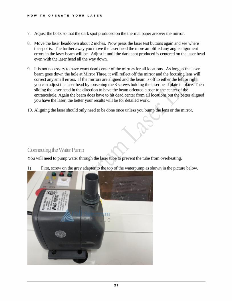
You will need to pump water through the laser tube to prevent the tube from overheating.
1) First, screw on the grey adapter to the top of the waterpump as shown in the picture below.

H O W T O O P E R A T E Y O U R L A S E R
22
2) Next, connect the clear adapter to the grey adapter you just screwed into the top of the water
pump. This is done by pushing the clear adapter into the grey adapter until it is firmly seated.
3) Next, connect one end of the clear tubingcoming from the back of the laser unit, the water
inlet labeled 6 on page 4, to the clear adapter. Slide the tubing over the innernipple on the clear
adapter, as shown in the picture below.
4) Verify the water is cycling through the tube. Fill a 5gallon bucket half way with distilled
water. Put the water pump into the bucket and plug it in. Grab the non-connected endof tubing, the
water outlet labeled 7 on page 4 of this manual, and verify the water is being pumped through.

H O W T O O P E R A T E Y O U R L A S E R
23
Adjusting the Z-Plate
The Z-axis is raised or lowered with a belt that connects 4 screws. Under some circumstances the belt
can slip on one of the screws and cause the Z axis table to become uneven. If the Z-axis is not flat,
remove the sets of screws holding down the Z-table. A belt connects all the screws which raises or
lowers the Z table. Adjust each of the screws until they are level by holding the belt and twisting the
screws independently. The easiest way to do this is to remove the belt and drop all the screws as low
as they can go then reattach the belt.
H O W T O O P E R A T E Y O U R L A S E R
24
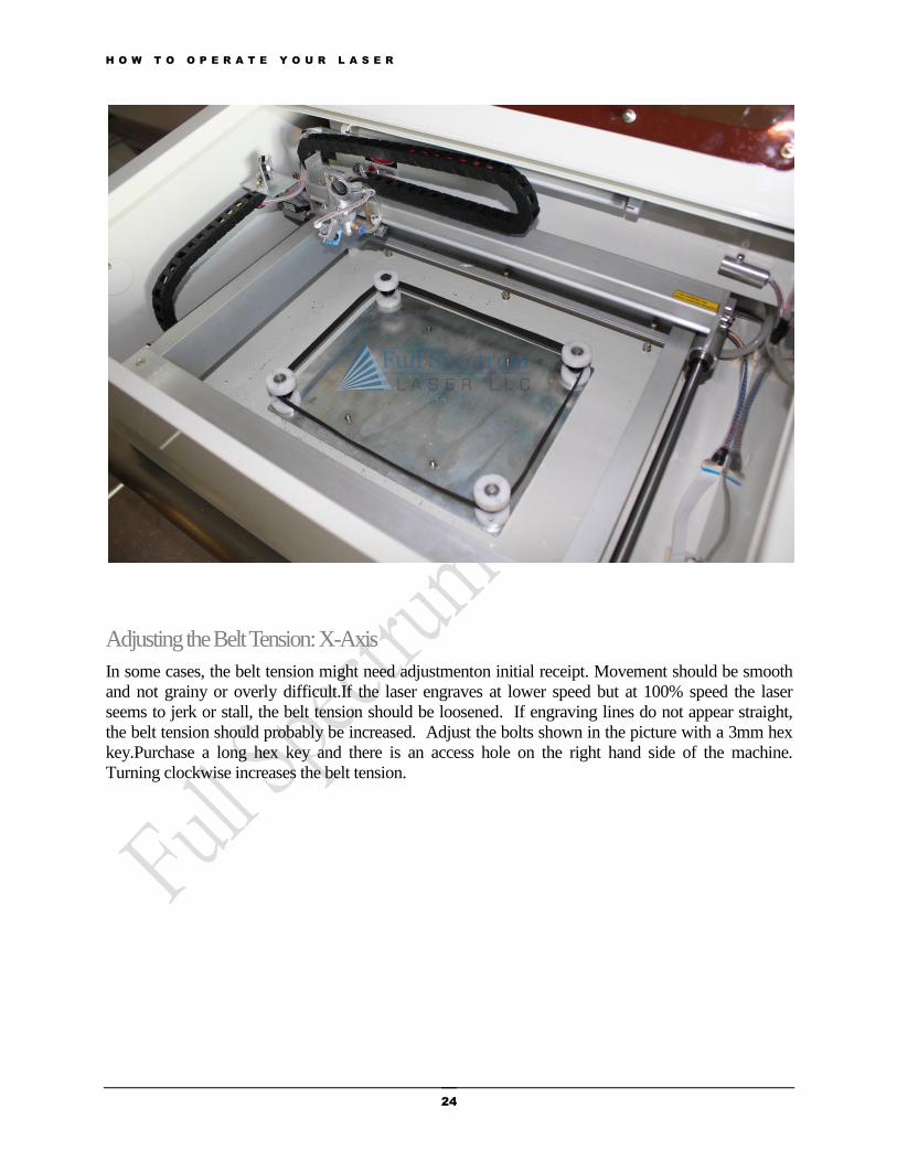
Adjusting the Belt Tension: X-Axis
In some cases, the belt tension might need adjustmenton initial receipt. Movement should be smooth
and not grainy or overly difficult.If the laser engraves at lower speed but at 100% speed the laser
seems to jerk or stall, the belt tension should be loosened. If engraving lines do not appear straight,
the belt tension should probably be increased. Adjust the bolts shown in the picture with a 3mm hex
key.Purchase a long hex key and there is an access hole on the right hand side of the machine.
Turning clockwise increases the belt tension.

H O W T O O P E R A T E Y O U R L A S E R
25
If the belt tension has been adjusted correctly and the movement of the laser head still moves with
grainy or overly difficult motion then you may also need to adjust the wheels attached to the laser
head. Turning the screw clockwise will tighten the wheel. However we recommend against adjusting
it from on top because you can only turn it one way.
H O W T O O P E R A T E Y O U R L A S E R
26
Instead use a short eyeglass type flat head screwdriver like this and adjust from the bottom of laser
carriage:
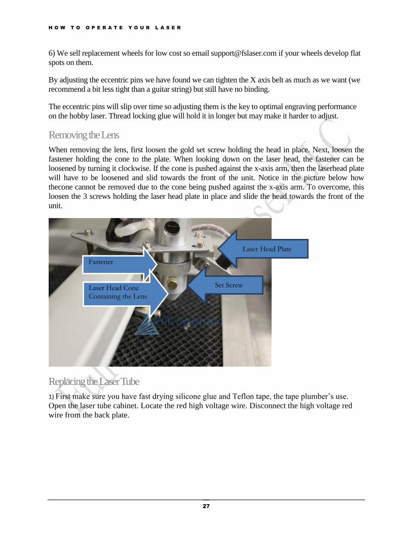
Once you have the right screwdriver it is very easy to turn the eccentric pin through the hole
underneath circled blue (after loosening the set screw circled green). You can use a mirror to view
from the bottom:
1) Loosen the 4 eccentric pins by using the short screwdriver from the bottom. The laserhead will not
be clamped to the X axis gantry anymore.
2) Adjust the top 2 eccentric screws so they that the laserhead is straight with the X axis. Since they
are eccentric you want the laserhead platform straight otherwise the belt will be pulled at a angle.
3) Adjust the bottom 2 eccentric screws so that the laserhead is as loose as possible but all 4 wheels
are just barely still rolling.
4) Insert the 4x set screws with the hex heads back and tighten. Note that by putting the set screws
back in it will tighten the eccentric pins slightly so that is why we say adjust as loose as possible but
still rolling in step 3.
5) Test it out and ensure the X axis is not binding during rastering. If you would like you can insert
some WEAK thread locking glue on the screws.
H O W T O O P E R A T E Y O U R L A S E R
27
6) We sell replacement wheels for low cost so email [email protected] if your wheels develop flat
spots on them.
By adjusting the eccentric pins we have found we can tighten the X axis belt as much as we want (we
recommend a bit less tight than a guitar string) but still have no binding.
The eccentric pins will slip over time so adjusting them is the key to optimal engraving performance
on the hobby laser. Thread locking glue will hold it in longer but may make it harder to adjust.
Removing the Lens
When removing the lens, first loosen the gold set screw holding the head in place. Next, loosen the
fastener holding the cone to the plate. When looking down on the laser head, the fastener can be
loosened by turning it clockwise. If the cone is pushed against the x-axis arm, then the laserhead plate
will have to be loosened and slid towards the front of the unit. Notice in the picture below how
thecone cannot be removed due to the cone being pushed against the x-axis arm. To overcome, this
loosen the 3 screws holding the laser head plate in place and slide the head towards the front of the
unit.
Replacing the Laser Tube
1) First make sure you have fast drying silicone glue and Teflon tape, the tape plumber’s use.
Open the laser tube cabinet. Locate the red high voltage wire. Disconnect the high voltage red
wire from the back plate.
Fastener
Laser Head Cone Containing the Lens
Laser Head Plate
Set Screw

H O W T O O P E R A T E Y O U R L A S E R
28
Warning: Pulling on the wire will break the laser tube at the neck.
Alternatively, using one hand, grasp the white insulation. Using your other hand, support the
neck of the laser tube where the red wire is connected to the laser tube. Attempt to pull the
insulation up the red wire to expose the soldered connection point. Do not pull on the red wire
because it is connected to the laser tube. Pull only on the insulation to move it up the wire sheath.
Cut the copper wire off after pulling the insulation back.
2) Unclamp the tube using a 3mm hex key.
3) Put in the new tube.
1) Take approximately 12 inches of Teflon tape, the same tape plumber’s use.
Clear Tubing
High Voltage Red Wire

H O W T O O P E R A T E Y O U R L A S E R
29
5) Wrap the Teflon tape around the wire and the connector and tie it in a knot. Make sure the
clear tubing is pulled back up the wire.
.
H O W T O O P E R A T E Y O U R L A S E R
30
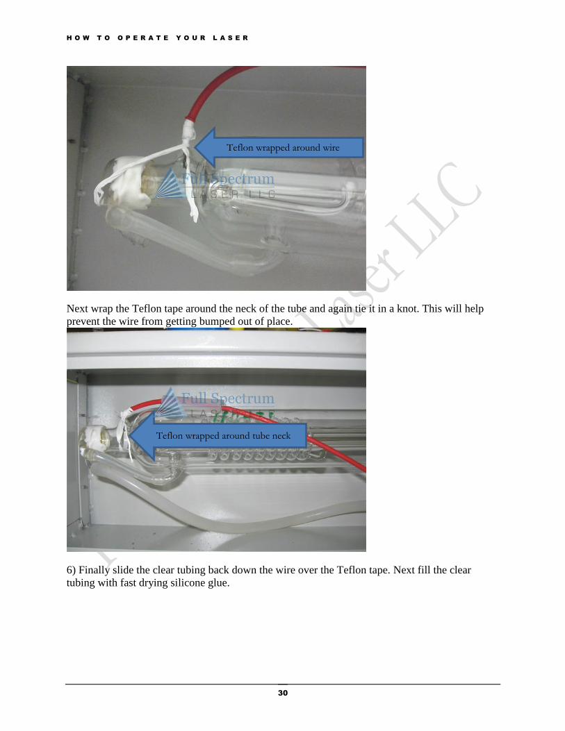
Next wrap the Teflon tape around the neck of the tube and again tie it in a knot. This will help
prevent the wire from getting bumped out of place.
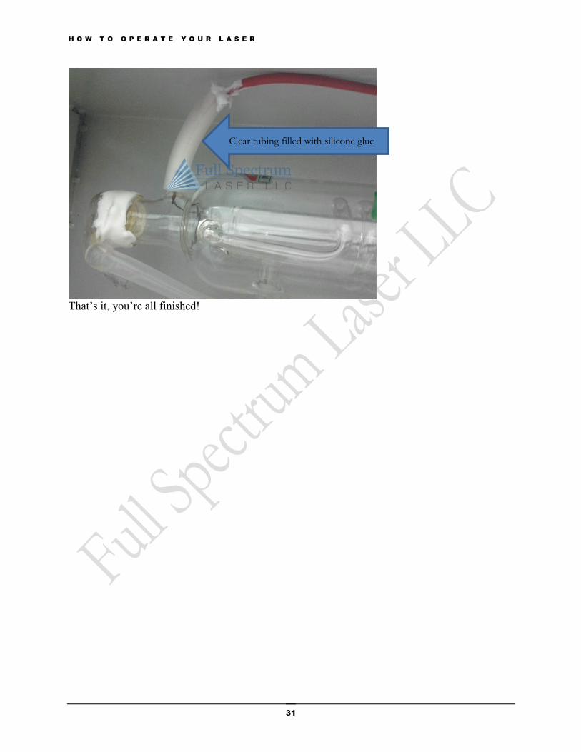
6) Finally slide the clear tubing back down the wire over the Teflon tape. Next fill the clear
tubing with fast drying silicone glue.
Teflon wrapped around wire
Teflon wrapped around tube neck
H O W T O O P E R A T E Y O U R L A S E R
31
That’s it, you’re all finished!
Clear tubing filled with silicone glue
H O W T O O P E R A T E Y O U R L A S E R
32
RetinaEngrave USB Software installation Your laser has 2 control options: Mach3/EMC2 control card/motor driver via a parallel
cable (Basic Laser) and RetinaEngrave USB (requires optional RetinaEngrave USB
Controller, included in Deluxe Laser).
Mach3/EMC2
Connect the laser to the parallel port with a DB25 Male to Female cable (not included) no longer
than 6 ft.
If connecting through the parallel port, download applicable drivers and the Mach3 application
from: www.machsupport.com. A free demo version is available, limited to 500 lines of G-Code
or less.
For Linux systems, EMC2 is available free of charge fromwww.linuxcnc.org
Mach3/EMC2 software is not produced or sold by Full Spectrum Laser LLC and software support
must be handled directly by directly contacting the respective software authors listed above.
Mach3/EMC2 are not trivial programs to use and Full Spectrum Laser LLC recommends our own
software package and control system RetinaEngrave USB
RetinaEngraveUSB
RetinaEngrave USBis the easiest to use, most accurate and most powerful laser control program,
written by Full Spectrum Laser LLC. As RetinaEngrave USB is written by Full Spectrum Laser LLC,
we provide support using this software package through our support forums at
http://www.fullspectrumengineering.com/forums. Download the appropriate software installation
package at http://fslaser.com/resources/software-manual-downloads. Consult the paperwork included
with your laser for login credentials. Consult our RetinaEngrave Software Manual for more
information.
H O W T O O P E R A T E Y O U R L A S E R
33
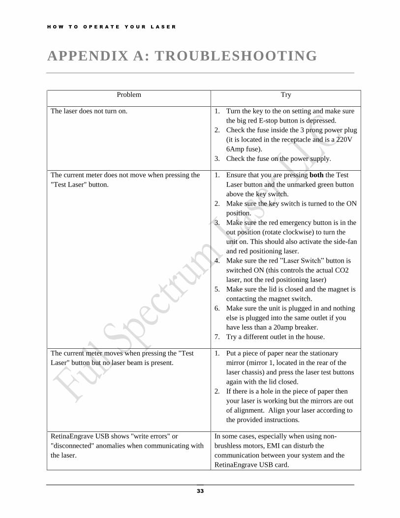
APPENDIX A: TROUBLESHOOTING
Problem Try
The laser does not turn on. 1. Turn the key to the on setting and make sure
the big red E-stop button is depressed.
2. Check the fuse inside the 3 prong power plug
(it is located in the receptacle and is a 220V
6Amp fuse).
3. Check the fuse on the power supply.
The current meter does not move when pressing the
"Test Laser" button.
1. Ensure that you are pressing both the Test
Laser button and the unmarked green button
above the key switch.
2. Make sure the key switch is turned to the ON
position.
3. Make sure the red emergency button is in the
out position (rotate clockwise) to turn the
unit on. This should also activate the side-fan
and red positioning laser.
4. Make sure the red ”Laser Switch” button is
switched ON (this controls the actual CO2
laser, not the red positioning laser)
5. Make sure the lid is closed and the magnet is
contacting the magnet switch.
6. Make sure the unit is plugged in and nothing
else is plugged into the same outlet if you
have less than a 20amp breaker.
7. Try a different outlet in the house.
The current meter moves when pressing the "Test
Laser" button but no laser beam is present.
1. Put a piece of paper near the stationary
mirror (mirror 1, located in the rear of the
laser chassis) and press the laser test buttons
again with the lid closed.
2. If there is a hole in the piece of paper then
your laser is working but the mirrors are out
of alignment. Align your laser according to
the provided instructions.
RetinaEngrave USB shows "write errors" or
"disconnected" anomalies when communicating with
the laser.
In some cases, especially when using non-
brushless motors, EMI can disturb the
communication between your system and the
RetinaEngrave USB card.
H O W T O O P E R A T E Y O U R L A S E R
34
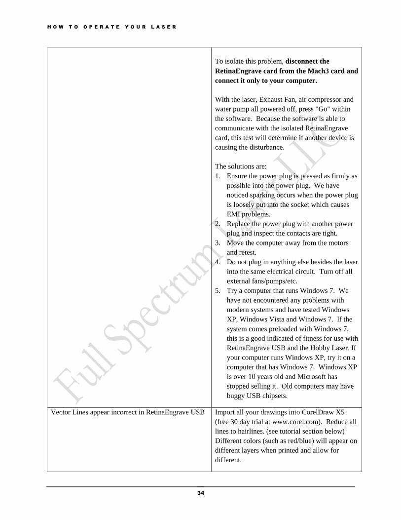
To isolate this problem, disconnect the
RetinaEngrave card from the Mach3 card and
connect it only to your computer.
With the laser, Exhaust Fan, air compressor and
water pump all powered off, press "Go" within
the software. Because the software is able to
communicate with the isolated RetinaEngrave
card, this test will determine if another device is
causing the disturbance.
The solutions are:
1. Ensure the power plug is pressed as firmly as
possible into the power plug. We have
noticed sparking occurs when the power plug
is loosely put into the socket which causes
EMI problems.
2. Replace the power plug with another power
plug and inspect the contacts are tight.
3. Move the computer away from the motors
and retest.
4. Do not plug in anything else besides the laser
into the same electrical circuit. Turn off all
external fans/pumps/etc.
5. Try a computer that runs Windows 7. We
have not encountered any problems with
modern systems and have tested Windows
XP, Windows Vista and Windows 7. If the
system comes preloaded with Windows 7,
this is a good indicated of fitness for use with
RetinaEngrave USB and the Hobby Laser. If
your computer runs Windows XP, try it on a
computer that has Windows 7. Windows XP
is over 10 years old and Microsoft has
stopped selling it. Old computers may have
buggy USB chipsets.
Vector Lines appear incorrect in RetinaEngrave USB Import all your drawings into CorelDraw X5
(free 30 day trial at www.corel.com). Reduce all
lines to hairlines. (see tutorial section below)
Different colors (such as red/blue) will appear on
different layers when printed and allow for
different.
H O W T O O P E R A T E Y O U R L A S E R
35
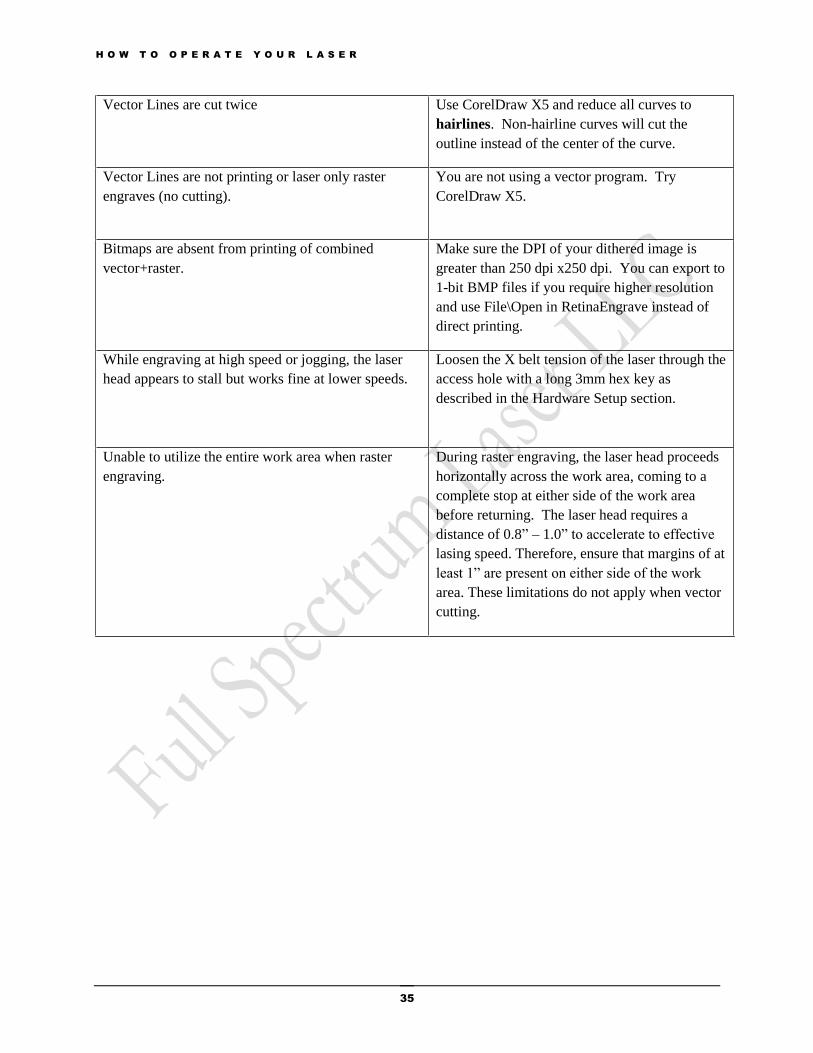
Vector Lines are cut twice Use CorelDraw X5 and reduce all curves to
hairlines. Non-hairline curves will cut the
outline instead of the center of the curve.
Vector Lines are not printing or laser only raster
engraves (no cutting).
You are not using a vector program. Try
CorelDraw X5.
Bitmaps are absent from printing of combined
vector+raster.
Make sure the DPI of your dithered image is
greater than 250 dpi x250 dpi. You can export to
1-bit BMP files if you require higher resolution
and use File\Open in RetinaEngrave instead of
direct printing.
While engraving at high speed or jogging, the laser
head appears to stall but works fine at lower speeds.
Loosen the X belt tension of the laser through the
access hole with a long 3mm hex key as
described in the Hardware Setup section.
Unable to utilize the entire work area when raster
engraving.
During raster engraving, the laser head proceeds
horizontally across the work area, coming to a
complete stop at either side of the work area
before returning. The laser head requires a
distance of 0.8” – 1.0” to accelerate to effective
lasing speed. Therefore, ensure that margins of at
least 1” are present on either side of the work
area. These limitations do not apply when vector
cutting.
H O W T O O P E R A T E Y O U R L A S E R
36
APPENDIX B: SPECIFICATIONS
Outside Dimensions (LxWxH): 31.5"x20"x12"
Boxed Dimensions (LxWxH): 38"x27"x17"
Net Weight: 70lbs
Gross Weight (boxed): 80lbs
Maximum material size: 13"x16"
Maximum engrave-able area:9.5"x14.5"
Standard Lens: ZnSe 2" FL
Maximum material thickness: 2.75" (with Z table removed and 2" FL lens, 3.25" with optional 1.5"
FL lens)
CO2 Laser Wavelength: 10.6um
Maximum Laser Power: 40W Peak (30-35W Average)
Maximum Power Requirements: 660W (main laser unit only; excludes water pump/fan/computer/
accessories)
Important:The current meter is used to tell how much power is going to the laser.
Keep the current under 15mA for maximum laser tube life.
H O W T O O P E R A T E Y O U R L A S E R
37
APPENDIX C: WARRANTY STATEMENT
Full Spectrum Laser LLC warrants to the original purchaser of 40w Hobby Laser that this product will be
free from defects in material or workmanship when purchased, and under proper, normal use within 60
days from the original date of purchase unless an extended warranty option is purchased.
Full Spectrum Laser will replace or, at its option, repair the defective part(s). Normally, Full Spectrum
Laser will supply a replacement part for the customer to replace. Once the replacement has been
performed, the replaced part must be returned to Full Spectrum Laser.
In the case where repair is required, Full Spectrum Laser requires that the defective part, or machine, be
returned to the Full Spectrum Laser facility.
Full Spectrum Laser will be responsible solely for the cost of parts only. All other costs for replacement
or repair, including, but not limited to, packaging and shipping both to and from Full Spectrum Laser,
shall be paid by the owner. A “Core” charge may be required by Full Spectrum Laser to insure the return
of replacement and repair parts.
This warranty excludes any damage from abuse (including, without limitation, incorrect voltages, power
surges, fires, improper or insufficient ventilation, cutting of corrosive gas producing materials such as
PVC or ABS, “acts of God” or other situations out of the control of Full Spectrum Laser), failure to
operate in accordance with instructions provided in the Owner’s Manuals for the Full Spectrum Laser
40w Hobby Laser, including specific safety and operational warnings contained therein, cosmetic damage
sustained in use, and damage caused by unauthorized modifications of any equipment. All warranties to
original purchasers are non-transferable. The registered owner must initiate warranty claims within the
warranty period.
THE ABOVE AND FOREGOING IS THE ONLY WARRANTY OF ANY KIND, EITHER
EXPRESS OR IMPLIED; INCLUDING BUT NOT LIMITED TO ANY WARRANTIES OF
MERCHANTABILITY AND FITNESS FOR A PARTICULAR PURPOSE THAT ARE MADE
BY FULL SPECTRUM LASER ON THE 40W HOBBY LASER. ANY WARRANTIES IMPLIED
BY LAW ARE HEREBY EXPRESSLY DISCLAIMED.
No oral or written information or advice given by Full Spectrum Laser, its dealers, itsdistributors, agents,
officers, or employees shall create a warranty or in any way increase the scope of thiswarranty. Neither
Full Spectrum Laser nor anyone else who has been involved in the creation, production, or deliveryof the
Full Spectrum Laser 40w Hobby Laser shall be liable for any direct, indirect, consequential, or incidental
damages,including but not limited to damages for loss of business profits, business interruption, loss of
businessinformation, adverse health impacts, fire, and the like, arising out of the use or inability to use
theseproducts.
Full Spectrum Laser LLC provides no warranties whatsoever on any software used in connection with
Full Spectrum Laser LLC products.


![ModBusTCP Setup&Operation Manual [B-82844EN 01]](https://static.fdocuments.us/doc/165x107/55cf85cb550346484b91639f/modbustcp-setupoperation-manual-b-82844en-01.jpg)