Hardware Installation Guide - D-Link
53
Hardware Installation Guide Product Model : DGS-1210/ME Series Metro Ethernet Switches Release 2.11 ©Copyright 2016. All rights reserved.
Transcript of Hardware Installation Guide - D-Link

Hardware Installation GuideProduct Model : DGS-1210/ME SeriesMetro Ethernet SwitchesRelease 2.11
©Copyright 2016. All rights reserved.

DGS-1210/ME series Metro Ethernet Switch Hardware Installation Guide
iiii
Information in this document is subject to change without notice. © 2016 D-Link Computer Corporation. All rights reserved. Reproduction in any manner whatsoever without the written permission of D-Link Computer Corporation is
strictly forbidden.
Trademarks used in this text: D-Link and the D-Link logo are trademarks of D-Link Computer Corporation;
Microsoft and Windows are registered trademarks of Microsoft Corporation.
Other trademarks and trade names may be used in this document to refer to either the entities claiming the
marks and names or their products. D-Link Computer Corporation disclaims any proprietary interest in
trademarks and trade names other than its own.
FCC Warning This equipment has been tested and found to comply with the limits for a Class A digital device, pursuant to
Part 15 of the FCC Rules. These limits are designed to provide reasonable protection against harmful
interference when the equipment is operated in a commercial environment. This equipment generates, uses,
and can radiate radio frequency energy and, if not installed and used in accordance with this user’s guide,
may cause harmful interference to radio communications. Operation of this equipment in a residential area is
likely to cause harmful interference in which case the user will be required to correct the interference at
hisown expense.
CE EMI CLASS A WARNING This equipment is compliant with Class A of CISPR 32. In a residential environment this equipment may cause radio interference.
October, 2016

DGS-1210/ME series Metro Ethernet Switch Hardware Installation Guide
ii
Table of Contents
Table of Contents ............................................................................................................................................. i Intended Readers ............................................................................................................................................. 1
Typographical Conventions ........................................................................................................................... 1 Notes and Cautions ........................................................................................................................................ 1 Safety Instructions .......................................................................................................................................... 1
Safety Cautions .......................................................................................................................................... 1 General Precautions for Rack-Mountable .................................................................................................. 2 Protecting Against Electrostatic Discharge ................................................................................................ 3
1 Product Introduction ................................................................................................................................... 4 Switch Description .......................................................................................................................................... 4 Front Panel Description.................................................................................................................................. 4 LED Indicators ................................................................................................................................................ 8 Rear Panel Description ................................................................................................................................ 10 Side Panel Description ................................................................................................................................. 12 Gigabit Fiber Ports ....................................................................................................................................... 12 Connecting the DPS-200A/500A/500DC to the RPS Port (for DGS-1210-10/12TS/20/28/28X/28XS/52/ME only).............................................................................................................................................................. 13 Installing the RPS into a Rack-mount Chassis (for DGS-1210-10/12TS/20/28/28X/28XS/52/ME only) ..... 14
DPS-800 Rack-mount Chassis ................................................................................................................. 14 2 Installation .................................................................................................................................................. 15
Step 1: Package Contents ........................................................................................................................... 15 Step 2: Installation Guidelines ..................................................................................................................... 15
Desktop or Shelf Installation ..................................................................................................................... 15 Rack Installation ....................................................................................................................................... 15
Step 3 – Plugging in the AC Power Cord ..................................................................................................... 16 Power Failure ........................................................................................................................................... 17
3 Switch Management .................................................................................................................................. 18 Management Options ................................................................................................................................... 18 Using Web-based Management .................................................................................................................. 18
Supported Web Browsers ........................................................................................................................ 18 Connecting to the Switch .......................................................................................................................... 18 Login Web-based Management ............................................................................................................... 19
Connecting the Console Port ....................................................................................................................... 19 To connect a terminal to the console port ................................................................................................ 19 Password Protection................................................................................................................................. 20 Assigning IP Addresses ........................................................................................................................... 21 SNMP Settings ......................................................................................................................................... 22 Traps ........................................................................................................................................................ 23 Management Information Base (MIB) ...................................................................................................... 23
4 Web-based Switch Configuration ............................................................................................................ 24 Logging onto the Web Manager ................................................................................................................... 24 Web-based User Interface ........................................................................................................................... 24 Areas of the User Interface .......................................................................................................................... 24 Web Pages ................................................................................................................................................... 25
Appendix A – Ethernet Technology ............................................................................................................. 27 Appendix B – Cables and Connectors ........................................................................................................ 34 Appendix C – Module Specs and Cable Lengths ....................................................................................... 36

DGS-1210/ME series Metro Ethernet Switch Hardware Installation Guide
1
Intended Readers
The DGS-1210/ME Series Hardware Installation Guide contains information for set up and management of the Switch. This manual is intended for network managers familiar with network management concepts and terminology. For all practical reasons all the switches in this series will be simply referred to as the Switch throughout this manual. All example screenshots are taken from the DGS-1210-28/ME Switch.
Typographical Conventions
Convention Description
[] In a command line, square brackets indicate an optional entry. For example: [copy filename] means that optionally you can type copy followed by the name of the file. Do not type the brackets.
Bold font
Indicates a button, a toolbar icon, menu, or menu item. For example: Open the File menu and choose Cancel. Used for emphasis. May also indicate system messages or prompts appearing on screen. For example: You have mail. Bold font is also used to represent filenames, program names and commands. For example: use the copy command.
Boldface Typewriter Font
Indicates commands and responses to prompts that must be typed exactly as printed in the manual.
Initial Capital Letter Indicates a window name. Names of keys on the keyboard have initial capitals. For example: Click Enter.
Italics Indicates a window name or a field. Also can indicate a variables or parameter that is replaced with an appropriate word or string. For example: type filename means that the actual filename should be typed instead of the word shown in italic.
Menu Name > Menu Option
Menu Name > Menu Option Indicates the menu structure. Device > Port > Port Properties means the Port Properties menu option under the Port menu option that is located under the Device menu.
Notes and Cautions In this guide, the term “Switch” (first letter capitalized) refers to DGS-1210/ME Metro Ethernet Switch, and “switch” (first letter lower case) refers to other Ethernet switches. Some technologies refer to terms “switch”, “bridge” and “switching hubs” interchangeably, and both are commonly accepted for Ethernet switches.
A NOTE indicates important information that helps make better use of the device.
A CAUTION indicates potential property damage or personal injury.
Safety Instructions Use the following safety guidelines to ensure your own personal safety and to help protect your system from
potential damage. Throughout this safety section, the caution icon ( ) is used to indicate cautions and precautions that need to be reviewed and followed. Safety Cautions To reduce the risk of bodily injury, electrical shock, fire, and damage to the equipment observe the following precautions:
• Observe and follow service markings. - Do not service any product except as explained in the system documentation. - Opening or removing covers that are marked with the triangular symbol with a lightning

DGS-1210/ME series Metro Ethernet Switch Hardware Installation Guide
2
bolt may expose the user to electrical shock. - Only a trained service technician should service components inside these compartments.
• If any of the following conditions occur, unplug the product from the electrical outlet and replace the part or contact your trained service provider:
- Damage to the power cable, extension cable, or plug. - An object has fallen into the product. - The product has been exposed to water. - The product has been dropped or damaged. - The product does not operate correctly when the operating instructions are correctly
followed. • Keep your system away from radiators and heat sources. Also, do not block cooling vents. • Do not spill food or liquids on system components, and never operate the product in a wet
environment. If the system gets wet, see the appropriate section in the troubleshooting guide or contact your trained service provider.
• Do not push any objects into the openings of the system. Doing so can cause fire or electric shock by shorting out interior components.
• Use the product only with approved equipment. • Allow the product to cool before removing covers or touching internal components. • Operate the product only from the type of external power source indicated on the electrical
ratings label. If unsure of the type of power source required, consult your service provider or local power company.
• To help avoid damaging the system, be sure the voltage selection switch (if provided) on the power supply is set to match the power available at the Switch’s location:
- 115 volts (V)/60 hertz (Hz) in most of North and South America and some Far Eastern countries such as South Korea and Taiwan
- 100 V/50 Hz in eastern Japan and 100 V/60 Hz in western Japan - 230 V/50 Hz in most of Europe, the Middle East, and the Far East
• Also, be sure that attached devices are electrically rated to operate with the power available in your location.
• Use only approved power cable(s). If you have not been provided with a power cable for your system or for any AC-powered option intended for your system, purchase a power cable that is approved for use in your country. The power cable must be rated for the product and for the voltage and current marked on the product's electrical ratings label. The voltage and current rating of the cable should be greater than the ratings marked on the product.
• To help prevent electric shock, plug the system and peripheral power cables into properly grounded electrical outlets. These cables are equipped with three-prong plugs to help ensure proper grounding. Do not use adapter plugs or remove the grounding prong from a cable. If using an extension cable is necessary, use a 3-wire cable with properly grounded plugs.
• Observe extension cable and power strip ratings. Make sure that the total ampere rating of all products plugged into the extension cable or power strip does not exceed 80 percent of the ampere ratings limit for the extension cable or power strip.
• To help protect the system from sudden, transient increases and decreases in electrical power, use a surge suppressor, line conditioner, or uninterruptible power supply (UPS).
• Position system cables and power cables carefully; route cables so that they cannot be stepped on or tripped over. Be sure that nothing rests on any cables.
• Do not modify power cables or plugs. Consult a licensed electrician or your power company for site modifications. Always follow your local/national wiring rules.
• When connecting or disconnecting power to hot-pluggable power supplies, if offered with your system, observe the following guidelines:
- Install the power supply before connecting the power cable to the power supply. - Unplug the power cable before removing the power supply. - If the system has multiple sources of power, disconnect power from the system by
unplugging all power cables from the power supplies. • Move products with care; ensure that all casters and/or stabilizers are firmly connected to the
system. Avoid sudden stops and uneven surfaces. General Precautions for Rack-Mountable Observe the following precautions for rack stability and safety. Also, refer to the rack installation documentation.
• Systems are considered to be components in a rack. Thus, "component" refers to any system as
DGS-1210/ME series Metro Ethernet Switch Hardware Installation Guide
33
well as to various peripherals or supporting hardware.
CAUTION: Installing systems in a rack without the front and side stabilizers installed could cause the rack to tip over, potentially resulting in bodily injury under certain circumstances. Therefore, always install the stabilizers before installing components in the rack. After installing system/components in a rack, never pull more than one component out of the rack on its slide assemblies at one time. The weight of more than one extended component could cause the rack to tip over and may result in serious injury.
• Before working on the rack, make sure that the stabilizers are secured to the rack, extended to
the floor, and that the full weight of the rack rests on the floor. Install front and side stabilizers on a single rack or front stabilizers for joined multiple racks before working on the rack.
• Always load the rack from the bottom up, and load the heaviest item in the rack first. • Make sure that the rack is level and stable before extending a component from the rack. • Use caution when pressing the component rail release latches and sliding a component into or
out of a rack; the slide rails can pinch your fingers. • After a component is inserted into the rack, carefully extend the rail into a locking position, and
then slide the component into the rack. • Do not overload the AC supply branch circuit that provides power to the rack. The total rack load
should not exceed 80 percent of the branch circuit rating. • Ensure that proper airflow is provided to components in the rack. • Do not step on or stand on any component when servicing other components in a rack.
NOTE: A qualified electrician must perform all connections to DC power and to safety grounds. All electrical wiring must comply with applicable local or national codes and practices.
CAUTION: The system chassis must be positively grounded to the rack cabinet frame. Do not attempt to connect power to the system until grounding cables are connected. Completed power and safety ground wiring must be inspected by a qualified electrical inspector. An energy hazard will exist if the safety ground cable is omitted or disconnected.
Protecting Against Electrostatic Discharge Static electricity can harm delicate components inside the system. To prevent static damage, discharge static electricity from your body before touching any of the electronic components, such as the microprocessor. This can be done by periodically touching an unpainted metal surface on the chassis. The following steps can also be taken prevent damage from electrostatic discharge (ESD): 1. When unpacking a static-sensitive component from its shipping carton, do not remove the component
from the antistatic packing material until ready to install the component in the system. Just before unwrapping the antistatic packaging, be sure to discharge static electricity from your body.
2. When transporting a sensitive component, first place it in an antistatic container or packaging. 3. Handle all sensitive components in a static-safe area. If possible, use antistatic floor pads, workbench
pads and an antistatic grounding strap.

DGS-1210/ME series Metro Ethernet Switch Hardware Installation Guide
4
1 Product Introduction
Switch Description Front Panel Description LED Indicators Rear Panel Description Side Panel Description Gigabit Fiber Port Connecting the DPS-200A/500A/500DC to the RPS Port
(for DGS-1210-10/12TS/20/28/28X/28XS/52/ME only) Installing the RPS into a Rack-mount Chassis (for DGS-1210-10/12TS/20/28/28X/28XS/52/ME only)
Switch Description The DGS-1210/ME Metro Ethernet Switch is equipped with Copper ports (10/100/1000Mbps), SFP ports (1000Mbps) and SFP+ ports (10G) that can be used to attach various networking devices to the network like Computers, Notebooks, Print Servers, Network Attached Storage devices, IP Cameras, VoIP PBX devices, and other Switches. The Small Form Factor Portable (SFP) ports can be used together with fiber-optical transceivers in order to connect various other networking devices, using a fiber-optic connection, to the network at Gigabit Ethernet speeds over great distances. This DGS-1210/ME Metro Ethernet Switch provides unsurpassed performance, fault tolerance, scalability, robust security, standard-based interoperability and impressive technology to future-proof departmental and enterprise network deployments. It allows IGMP Snooping and Authentication, QoS, Bandwidth Control, ACL and many security functions. It can be managed by Web UI, or commands via Telnet. The DGS-1210/ME Metro Ethernet Switches have different port configuration (10/100/1000Base-T or SFP ports) that may be used in to uplink various network devices to the Switch, including PCs, hubs and other switches to provide a gigabit Ethernet uplink in full-duplex mode. The SFP (Small Form Factor Portable) ports are used with fiber-optical transceiver cabling in order to uplink various other networking devices for a gigabit link that may span great distances.
Front Panel Description The front panel of the DGS-1210-10/ME switch consists out of the following:
• 8 10/100/1000Mbps Copper Ports • 2 1000Mbps SFP port • One RJ-45 Console Port • LEDs for Power, Console, RPS, Link/Act for port 1 ~ 10
Figure 1.1 – DGS-1210-10/ME Front Panel
CAUTION: The MiniGBIC ports should use UL listed Optical Transceiver product, Rated Laser Class I. 3.3Vdc.
The front panel of the DGS-1210-10P/ME switch consists out of the following:
• 8 10/100/1000Mbps Copper Ports • 2 1000Mbps SFP ports • One RJ-45 Console Port
DGS-1210/ME series Metro Ethernet Switch Hardware Installation Guide
55
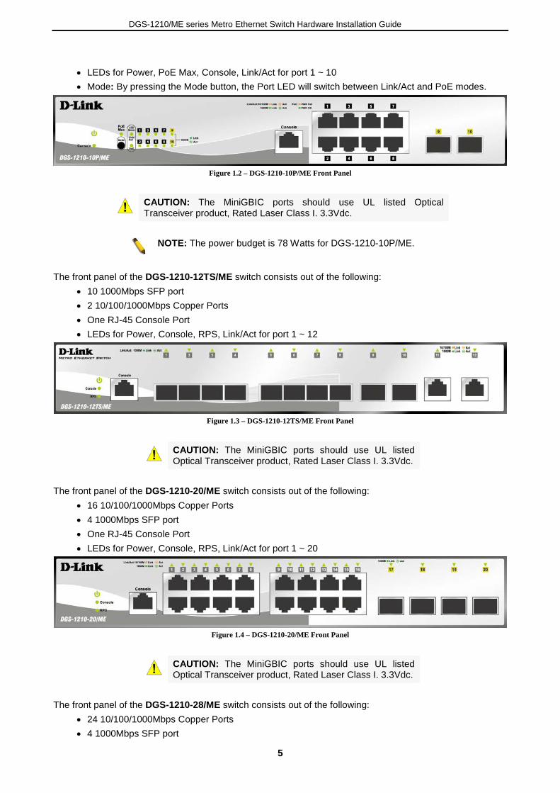
• LEDs for Power, PoE Max, Console, Link/Act for port 1 ~ 10 • Mode: By pressing the Mode button, the Port LED will switch between Link/Act and PoE modes.
Figure 1.2 – DGS-1210-10P/ME Front Panel
CAUTION: The MiniGBIC ports should use UL listed Optical Transceiver product, Rated Laser Class I. 3.3Vdc.
NOTE: The power budget is 78 Watts for DGS-1210-10P/ME.
The front panel of the DGS-1210-12TS/ME switch consists out of the following:
• 10 1000Mbps SFP port • 2 10/100/1000Mbps Copper Ports • One RJ-45 Console Port • LEDs for Power, Console, RPS, Link/Act for port 1 ~ 12
Figure 1.3 – DGS-1210-12TS/ME Front Panel
CAUTION: The MiniGBIC ports should use UL listed Optical Transceiver product, Rated Laser Class I. 3.3Vdc.
The front panel of the DGS-1210-20/ME switch consists out of the following:
• 16 10/100/1000Mbps Copper Ports • 4 1000Mbps SFP port • One RJ-45 Console Port • LEDs for Power, Console, RPS, Link/Act for port 1 ~ 20
Figure 1.4 – DGS-1210-20/ME Front Panel
CAUTION: The MiniGBIC ports should use UL listed Optical Transceiver product, Rated Laser Class I. 3.3Vdc.
The front panel of the DGS-1210-28/ME switch consists out of the following:
• 24 10/100/1000Mbps Copper Ports • 4 1000Mbps SFP port

DGS-1210/ME series Metro Ethernet Switch Hardware Installation Guide
6
• One RJ-45 Console Port • LEDs for Power, RPS, Console, Link/Act for port 1 ~ 28
Figure 1.5 – DGS-1210-28/ME Front Panel
CAUTION: The MiniGBIC ports should use UL listed Optical Transceiver product, Rated Laser Class I. 3.3Vdc.
The front panel of the DGS-1210-28P/ME switch consists out of the following:
• 24 10/100/1000Mbps Copper Ports • 4 1000Mbps SFP port • One RJ-45 Console Port • LEDs for Power, Console, Fan Error, Pwr Max, Link/Act for port 1 ~ 28 • Mode: By pressing the Mode button, the Port LED will switch between Link/Act and PoE modes
Figure 1.6 – DGS-1210-28P/ME Front Panel
CAUTION: The MiniGBIC ports should use UL listed Optical Transceiver product, Rated Laser Class I. 3.3Vdc.
NOTE: The power budget is 193 Watts for DGS-1210-28P/ME.
The front panel of the DGS-1210-28MP/ME switch consists out of the following:
• 24 10/100/1000Mbps Copper and PoE Ports • 4 1000Mbps SFP port • One RJ-45 Console Port • LEDs for Power, Console, Fan Error, Pwr Max, Link/Act for port 1 ~ 28 • Mode: By pressing the Mode button, the Port LED will switch between Link/Act and PoE modes
Figure 1.7 – DGS-1210-28MP/ME Front Panel
CAUTION: The MiniGBIC ports should use UL listed Optical Transceiver product, Rated Laser Class I. 3.3Vdc.
NOTE: The power budget is 370 Watts for DGS-1210-28MP/ME.
The front panel of the DGS-1210-28X/ME switch consists out of the following:
• 24 10/100/1000Mbps Copper Ports • 4 1000Mbps SFP/10G SFP+ port • One RJ-45 Console Port
DGS-1210/ME series Metro Ethernet Switch Hardware Installation Guide
77
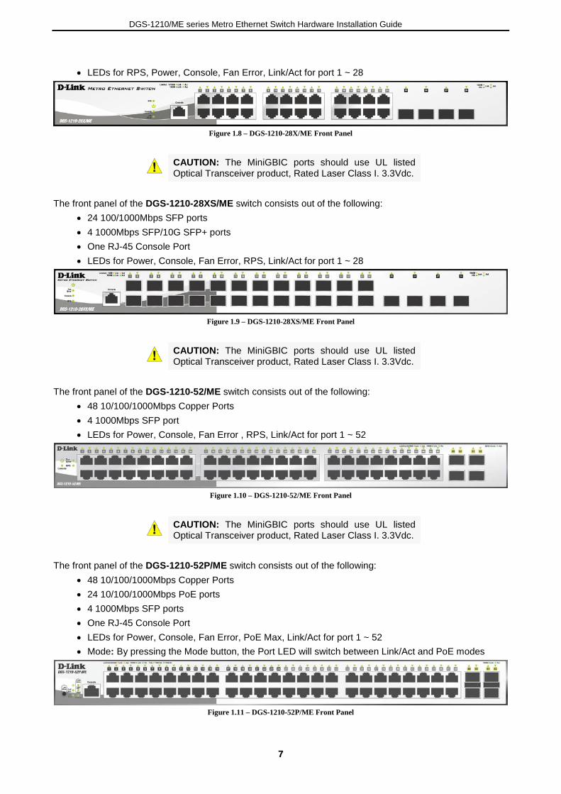
• LEDs for RPS, Power, Console, Fan Error, Link/Act for port 1 ~ 28
Figure 1.8 – DGS-1210-28X/ME Front Panel
CAUTION: The MiniGBIC ports should use UL listed Optical Transceiver product, Rated Laser Class I. 3.3Vdc.
The front panel of the DGS-1210-28XS/ME switch consists out of the following:
• 24 100/1000Mbps SFP ports • 4 1000Mbps SFP/10G SFP+ ports • One RJ-45 Console Port • LEDs for Power, Console, Fan Error, RPS, Link/Act for port 1 ~ 28
Figure 1.9 – DGS-1210-28XS/ME Front Panel
CAUTION: The MiniGBIC ports should use UL listed Optical Transceiver product, Rated Laser Class I. 3.3Vdc.
The front panel of the DGS-1210-52/ME switch consists out of the following:
• 48 10/100/1000Mbps Copper Ports • 4 1000Mbps SFP port • LEDs for Power, Console, Fan Error , RPS, Link/Act for port 1 ~ 52
Figure 1.10 – DGS-1210-52/ME Front Panel
CAUTION: The MiniGBIC ports should use UL listed Optical Transceiver product, Rated Laser Class I. 3.3Vdc.
The front panel of the DGS-1210-52P/ME switch consists out of the following:
• 48 10/100/1000Mbps Copper Ports • 24 10/100/1000Mbps PoE ports • 4 1000Mbps SFP ports • One RJ-45 Console Port • LEDs for Power, Console, Fan Error, PoE Max, Link/Act for port 1 ~ 52 • Mode: By pressing the Mode button, the Port LED will switch between Link/Act and PoE modes
Figure 1.11 – DGS-1210-52P/ME Front Panel

DGS-1210/ME series Metro Ethernet Switch Hardware Installation Guide
8
CAUTION: The MiniGBIC ports should use UL listed Optical Transceiver product, Rated Laser Class I. 3.3Vdc.
NOTE: The power budget is 193 Watts for DGS-1210-52P/ME.
The front panel of the DGS-1210-52MP/ME switch consists out of the following:
• 48 10/100/1000Mbps Copper and PoE Ports • 4 1000Mbps SFP ports • One RJ-45 Console Port • LEDs for Power, Console, Fan Error, PoE Max, Link/Act for port 1 ~ 52 • Mode: By pressing the Mode button, the Port LED will switch between Link/Act and PoE modes
Figure 1.12 – DGS-1210-52MP/ME Front Panel
CAUTION: The MiniGBIC ports should use UL listed Optical Transceiver product, Rated Laser Class I. 3.3Vdc.
NOTE: The power budget is 370 Watts for DGS-1210-52MP/ME.
The front panel of the DGS-1210-52MPP/ME switch consists out of the following:
• 48 10/100/1000Mbps Copper and PoE Ports • 4 1000Mbps SFP ports • One RJ-45 Console Port • LEDs for Power, Console, Fan Error, PoE Max, Link/Act for port 1 ~ 52 • Mode: By pressing the Mode button, the Port LED will switch between Link/Act and PoE modes
Figure 1.13 – DGS-1210-52MPP/ME Front Panel
CAUTION: The MiniGBIC ports should use UL listed Optical Transceiver product, Rated Laser Class I. 3.3Vdc.
NOTE: The power budget is 740 Watts for DGS-1210-52MPP/ME.
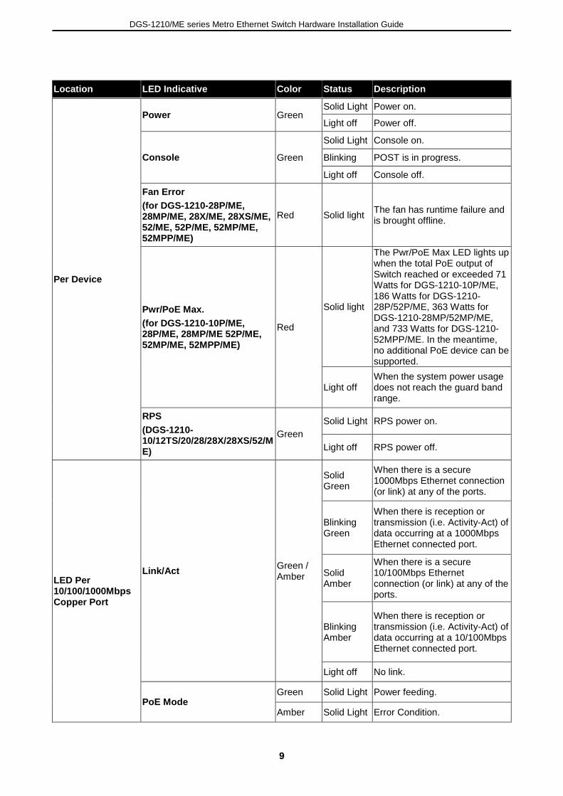
LED Indicators The Switch supports LED indicators for Power, Console, RPS, Fan, and Link/Act for each port. The following shows the LED indicators for the DGS-1210/ME Metro Ethernet Switch along with an explanation of each indicator.
Figure 1.14 –LED Indicators on DGS-1210/ME SERIES
DGS-1210/ME series Metro Ethernet Switch Hardware Installation Guide
99
Location LED Indicative Color Status Description
Per Device
Power Green Solid Light Power on.
Light off Power off.
Console Green
Solid Light Console on.
Blinking POST is in progress.
Light off Console off.
Fan Error (for DGS-1210-28P/ME, 28MP/ME, 28X/ME, 28XS/ME, 52/ME, 52P/ME, 52MP/ME, 52MPP/ME)
Red Solid light The fan has runtime failure and is brought offline.
Pwr/PoE Max. (for DGS-1210-10P/ME, 28P/ME, 28MP/ME 52P/ME, 52MP/ME, 52MPP/ME)
Red
Solid light
The Pwr/PoE Max LED lights up when the total PoE output of Switch reached or exceeded 71 Watts for DGS-1210-10P/ME, 186 Watts for DGS-1210-28P/52P/ME, 363 Watts for DGS-1210-28MP/52MP/ME, and 733 Watts for DGS-1210-52MPP/ME. In the meantime, no additional PoE device can be supported.
Light off When the system power usage does not reach the guard band range.
RPS (DGS-1210-10/12TS/20/28/28X/28XS/52/ME)
Green Solid Light RPS power on.
Light off RPS power off.
LED Per 10/100/1000Mbps Copper Port
Link/Act Green / Amber
Solid Green
When there is a secure 1000Mbps Ethernet connection (or link) at any of the ports.
Blinking Green
When there is reception or transmission (i.e. Activity-Act) of data occurring at a 1000Mbps Ethernet connected port.
Solid Amber
When there is a secure 10/100Mbps Ethernet connection (or link) at any of the ports.
Blinking Amber
When there is reception or transmission (i.e. Activity-Act) of data occurring at a 10/100Mbps Ethernet connected port.
Light off No link.
PoE Mode Green Solid Light Power feeding.
Amber Solid Light Error Condition.

DGS-1210/ME series Metro Ethernet Switch Hardware Installation Guide
10
Off Solid Off No Power feeding.
LED Per SFP Port Link/Act
Green
Solid Green
When there is a secure 1000Mbps Ethernet connection (or link) at any of the ports.
Blinking Green
When there is reception or transmission (i.e. Activity—Act) of data occurring at a 1000Mbps Ethernet connected port.
Amber
Solid Light When there is a secure 100Mbps connection at the port. (For DGS-1210-28XS/ME only)
Blinking Amber
When there is reception or transmission occurring at the port. (For DGS-1210-28XS/ME only)
Off Solid off No link.
LED Per 10G SFP+ Port (for DGS-1210-28X/ME, 28XS/ME)
Link/Act
Green
Solid Light When there is a secure 10Gbps connection at the port.
Blinking Green
When there is reception or transmission occurring at the port.
Amber
Solid Light When there is a secure 1000Mbps connection at the port.
Blinking Amber
When there is reception or transmission occurring at the port.
Off Solid off No link.
Rear Panel Description The rear panel of the Switch contains an AC power connector. The AC power connector is a standard three-pronged connector that supports the power cord. Plug-in the female connector of the provided power cord into this socket, and the male side of the cord into a power outlet. The Switch automatically adjusts its power setting to any supply voltage in the range from 100 to 240 VAC at 50 to 60 Hz. Connect the Kensington-compatible security lock, at the rear of the switch, to a secure immovable device. Insert the lock into the notch and turn the key to secure the lock. DGS-1210-10/ME
Figure 1.15 - DGS-1210-10/ME Rear Panel
DGS-1210-10P/ME
Figure 1.16- DGS-1210-10P/ME Rear Panel
DGS-1210/ME series Metro Ethernet Switch Hardware Installation Guide
1111
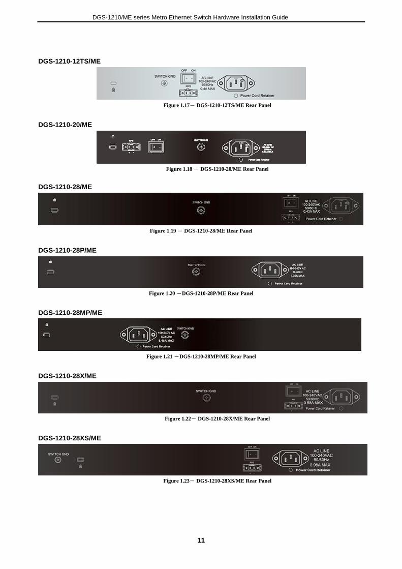
DGS-1210-12TS/ME
Figure 1.17- DGS-1210-12TS/ME Rear Panel
DGS-1210-20/ME
Figure 1.18 - DGS-1210-20/ME Rear Panel
DGS-1210-28/ME
Figure 1.19 - DGS-1210-28/ME Rear Panel
DGS-1210-28P/ME
Figure 1.20 -DGS-1210-28P/ME Rear Panel
DGS-1210-28MP/ME
Figure 1.21 -DGS-1210-28MP/ME Rear Panel
DGS-1210-28X/ME
Figure 1.22- DGS-1210-28X/ME Rear Panel
DGS-1210-28XS/ME
Figure 1.23- DGS-1210-28XS/ME Rear Panel

DGS-1210/ME series Metro Ethernet Switch Hardware Installation Guide
12
DGS-1210-52/ME
Figure 1.24 -DGS-1210-52/ME Rear Panel
DGS-1210-52P/ME
Figure 1.25 - DGS-1210-52P/ME Rear Panel
DGS-1210-52MP/ME
Figure 1.26 - DGS-1210-52MP/ME Rear Panel
DGS-1210-52MPP/ME
Figure 1.27 - DGS-1210-52MPP/ME Rear Panel
Side Panel Description The left- and right-hand panels of the Switch have heat vents to dissipate heat. Do not block these openings, and leave at least 6 inches of space at the rear and sides of the Switch for proper ventilation. Be reminded that without proper heat dissipation and air circulation, system components might overheat, which could lead to system failure.
Figure 1.28 - Side panels of the DGS-1210/ME SERIES
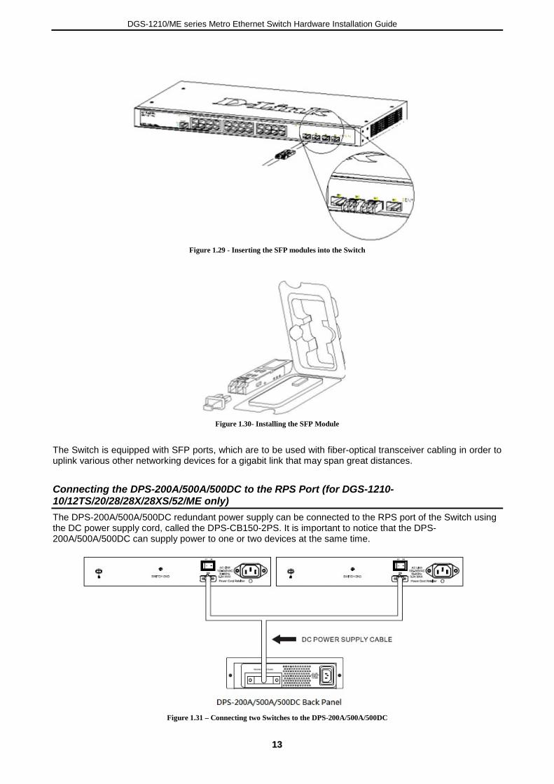
Gigabit Fiber Ports The DGS-1210/ME Series features support four Small Form Factor Portable (SFP) ports (optional). See the diagram below to view the four SFP port modules being plugged into the Switch.
DGS-1210/ME series Metro Ethernet Switch Hardware Installation Guide
1133
Figure 1.29 - Inserting the SFP modules into the Switch
Figure 1.30- Installing the SFP Module
The Switch is equipped with SFP ports, which are to be used with fiber-optical transceiver cabling in order to uplink various other networking devices for a gigabit link that may span great distances.
Connecting the DPS-200A/500A/500DC to the RPS Port (for DGS-1210-10/12TS/20/28/28X/28XS/52/ME only) The DPS-200A/500A/500DC redundant power supply can be connected to the RPS port of the Switch using the DC power supply cord, called the DPS-CB150-2PS. It is important to notice that the DPS-200A/500A/500DC can supply power to one or two devices at the same time.
Figure 1.31 – Connecting two Switches to the DPS-200A/500A/500DC
DGS-1210/ME series Metro Ethernet Switch Hardware Installation Guide
14
The following section explains how to connect the DPS-200A/500A/500DC to the Switch.
• Disconnect the Switch from the main AC power source. • Insert the 14-pin end of the DPS-CB150-2PS into the DPS-200A/500A/500DC and the 2-pin end into
the receptacle of the RPS port on the Switch. • Using a standard AC power cord, connect the DPS-200A/500A/500DC to the main AC power source.
A green LED on the front panel of the DPS-200A/500A/500DC will illuminate to indicate a successful connection.
• Make sure that the ON/OFF toggle switch on the rear panel of the Switch is turned on. • Re-connect the Switch to the AC power source and power on the 200A/500A/500DC.
No configuration is needed in the Switch software for this installation.
NOTE: See the DPS- DPS-200A/500A/500DC Quick Installation Guide for more information.
Installing the RPS into a Rack-mount Chassis (for DGS-1210-10/12TS/20/28/28X/28XS/52/ME only) The DPS-200A/500A/500DC are the redundant power supply units designed to conform to the voltage requirements of the RPS port of the Switch being supported. The DPS-200A/500A/500DC can be installed into a DPS-800 rack-mount chassis unit.
CAUTION: DO NOT connect the RPS to the AC power before the DC power cable is connected. Connecting the AC power before the DC power is connected might damage the internal power supply.
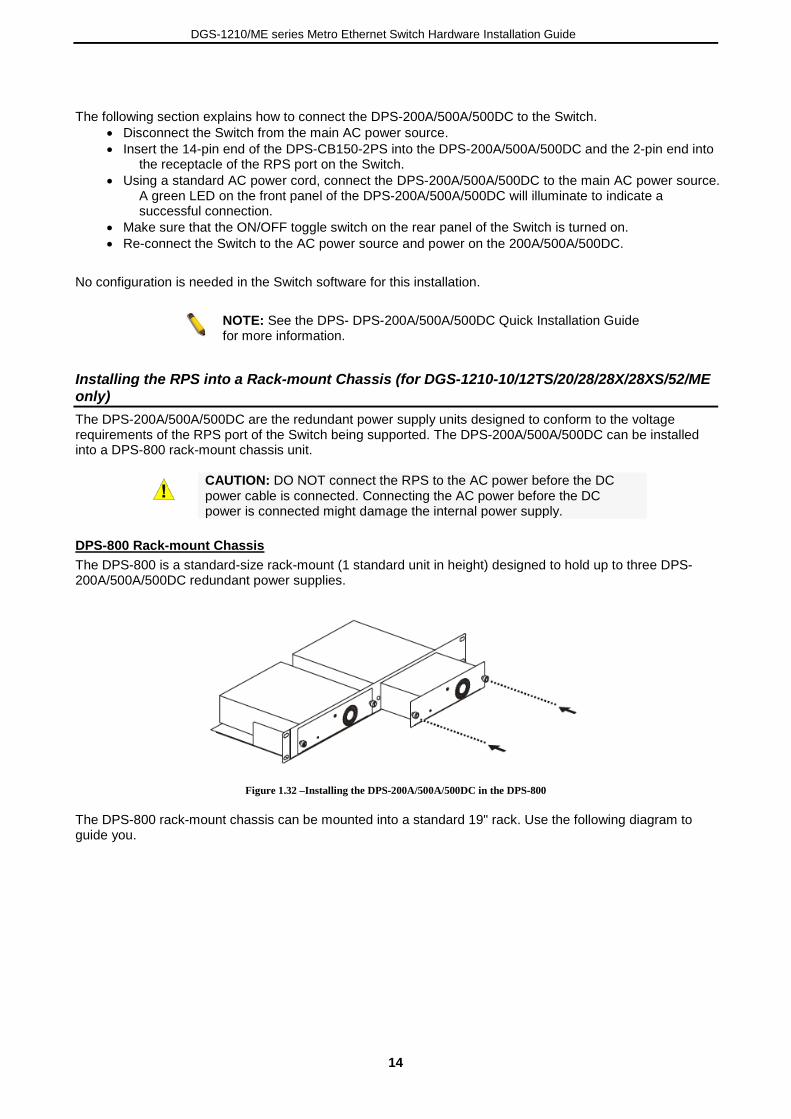
DPS-800 Rack-mount Chassis The DPS-800 is a standard-size rack-mount (1 standard unit in height) designed to hold up to three DPS-200A/500A/500DC redundant power supplies.
Figure 1.32 –Installing the DPS-200A/500A/500DC in the DPS-800
The DPS-800 rack-mount chassis can be mounted into a standard 19" rack. Use the following diagram to guide you.

DGS-1210/ME series Metro Ethernet Switch Hardware Installation Guide
1155
2 Installation
This chapter provides unpacking and installation information for the D-Link Metro Ethernet Switch.
Step 1: Package Contents Open the shipping carton and carefully unpack its contents. Please consult the packing list located in the User Manual to make sure all items are present and undamaged. If any item is missing or damaged, please contact your local D-Link reseller for replacement.
One D-Link Metro Ethernet Switch One multi-language Getting Started Guide One CD One RJ-45 console cable Power cord clip Power cord Rack mount kit Rubber feet
If any item is found missing or damaged, please contact the local reseller for replacement.
Step 2: Installation Guidelines For safe switch installation and operation, it is recommended that you:
Visually inspect the power cord to see that it is secured fully to the AC power connector. Make sure that there is proper heat dissipation and adequate ventilation around the switch. Do not place heavy objects on the switch.
Desktop or Shelf Installation When installing the switch on a desktop or shelf, the rubber feet included with the device must be attached on the bottom at each corner of the device’s base. Allow enough ventilation space between the device and the objects around it.
Figure 2.1 – Attach the adhesive rubber pads to the bottom
Rack Installation The switch can be mounted in an EIA standard size 19-inch rack, which can be placed in a wiring closet with other equipment. To install, attach the mounting brackets to the switch’s side panels (one on each side) and secure them with the screws provided (please note that these brackets are not designed for palm size switches).
Figure 2.2 – Attach the mounting brackets to the Switch

DGS-1210/ME series Metro Ethernet Switch Hardware Installation Guide
16
Then, use the screws provided with the equipment rack to mount the switch in the rack.
Figure 2.3 – Mount the Switch in the rack or chassis
Please be aware of following safety Instructions when installing: A) Elevated Operating Ambient - If installed in a closed or multi-unit rack assembly, the operating ambient temperature of the rack environment may be greater than room ambient. Therefore, consideration should be given to installing the equipment in an environment compatible with the maximum ambient temperature (Tma) specified by the manufacturer. B) Reduced Air Flow - Installation of the equipment in a rack should be such that the amount of air flow required for safe operation of the equipment is not compromised. C) Mechanical Loading - Mounting of the equipment in the rack should be such that a hazardous condition is not achieved due to uneven mechanical loading. D) Circuit Overloading - Consideration should be given to the connection of the equipment to the supply circuit, and the effect that overloading of the circuits might have on overcurrent protection and supply wiring. Appropriate consideration of equipment nameplate ratings should be used when addressing this concern. E) Reliable Earthing - Reliable earthing of rack-mounted equipment should be maintained. Particular attention should be given to supply connections other than direct connections to the branch circuit (e.g. use of power strips)."
Step 3 – Plugging in the AC Power Cord Users may now connect the AC power cord into the rear of the switch and to an electrical outlet (preferably one that is grounded and surge protected).

DGS-1210/ME series Metro Ethernet Switch Hardware Installation Guide
1177
Figure 2.4 – Plugging the switch into an outlet
Power Failure As a precaution, the switch should be unplugged in case of power failure. When power is resumed, plug the switch back in.
DGS-1210/ME series Metro Ethernet Switch Hardware Installation Guide
18
3 Switch Management
This chapter introduces the management interface of D-Link DGS-1210/ME Metro Ethernet Switch. Management Options Using Web-based Management Connecting to the Console Port
Management Options The D-Link Metro Ethernet Switch can be managed through any port on the device by using the Web-based Management or command line interface. Each switch must be assigned its own IP Address, which is used for communication with the Web-Based Management or a SNMP network manager. The PC should have an IP address in the same range as the switch. Each switch can allow up to four users to access the Web-Based Management concurrently. Please refer to the following installation instructions for the Web-based Management.
Using Web-based Management After a successful physical installation, you can configure the Switch, monitor the network status, and display statistics using a web browser. Supported Web Browsers The embedded Web-based Management currently supports the following web browsers:
Microsoft Internet Explorer 10/11 Microsoft Edge 25 Chrome 51 Safari 5.1.7
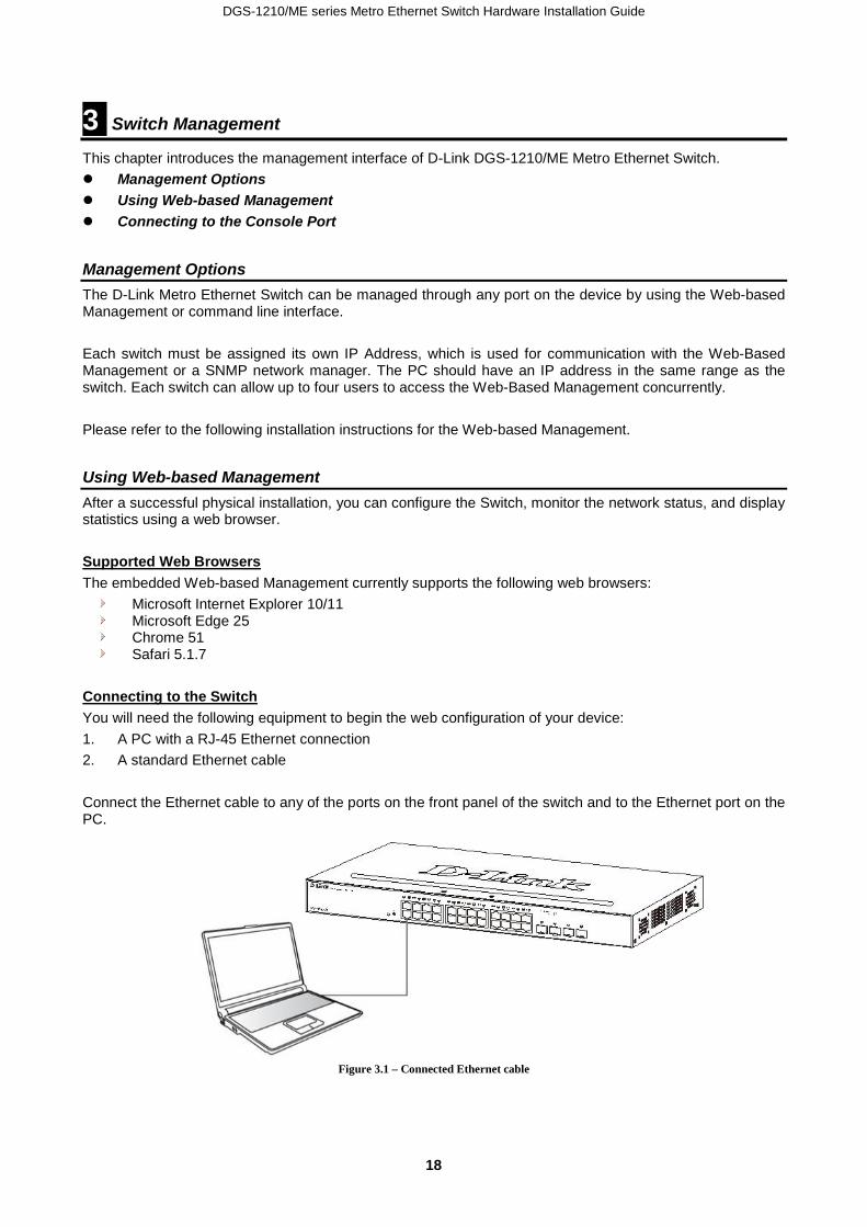
Connecting to the Switch You will need the following equipment to begin the web configuration of your device: 1. A PC with a RJ-45 Ethernet connection 2. A standard Ethernet cable Connect the Ethernet cable to any of the ports on the front panel of the switch and to the Ethernet port on the PC.
Figure 3.1 – Connected Ethernet cable

DGS-1210/ME series Metro Ethernet Switch Hardware Installation Guide
1199
Login Web-based Management In order to login and configure the switch via an Ethernet connection, the PC must have an IP address in the same subnet as the switch. For example, if the switch has an IP address of 10.90.90.90, the PC should have an IP address of 10.x.y.z (where x/y is a number between 0 ~ 254 and z is a number between 1 ~ 254), and a subnet mask of 255.0.0.0. Enter 10.90.90.90 (the factory default IP address) in the address bar of your web browser and press <Enter>.
Figure 3.2 –Enter the IP address 10.90.90.90 in the web browser
NOTE: The switch's factory default IP address is 10.90.90.90 with a subnet mask of 255.0.0.0 and a default gateway of 0.0.0.0.
When the following logon dialog box appears, enter the password and choose the language of the Web-based Management interface then click OK. By default, the Username and Password are empty.
Figure 3.3 – Logon Dialog Box
Connecting the Console Port The console port on the front panel of the Switch is used to connect a computer that monitors and configures the switch. The console port is an RJ-45 port and requires a special cable that is included with the switch, to establish the physical connection. To connect a terminal to the console port The console interface is used by connecting the Switch to a VT100-compatible terminal or a computer running an ordinary terminal emulator program (for example, the HyperTerminal program included with the Windows operating system) using an RJ-45 serial cable. Your terminal parameters will need to be set to:
• VT-100 compatible • Baud rate 9600bps • 8 data bits • No parity • One stop bit • No flow control
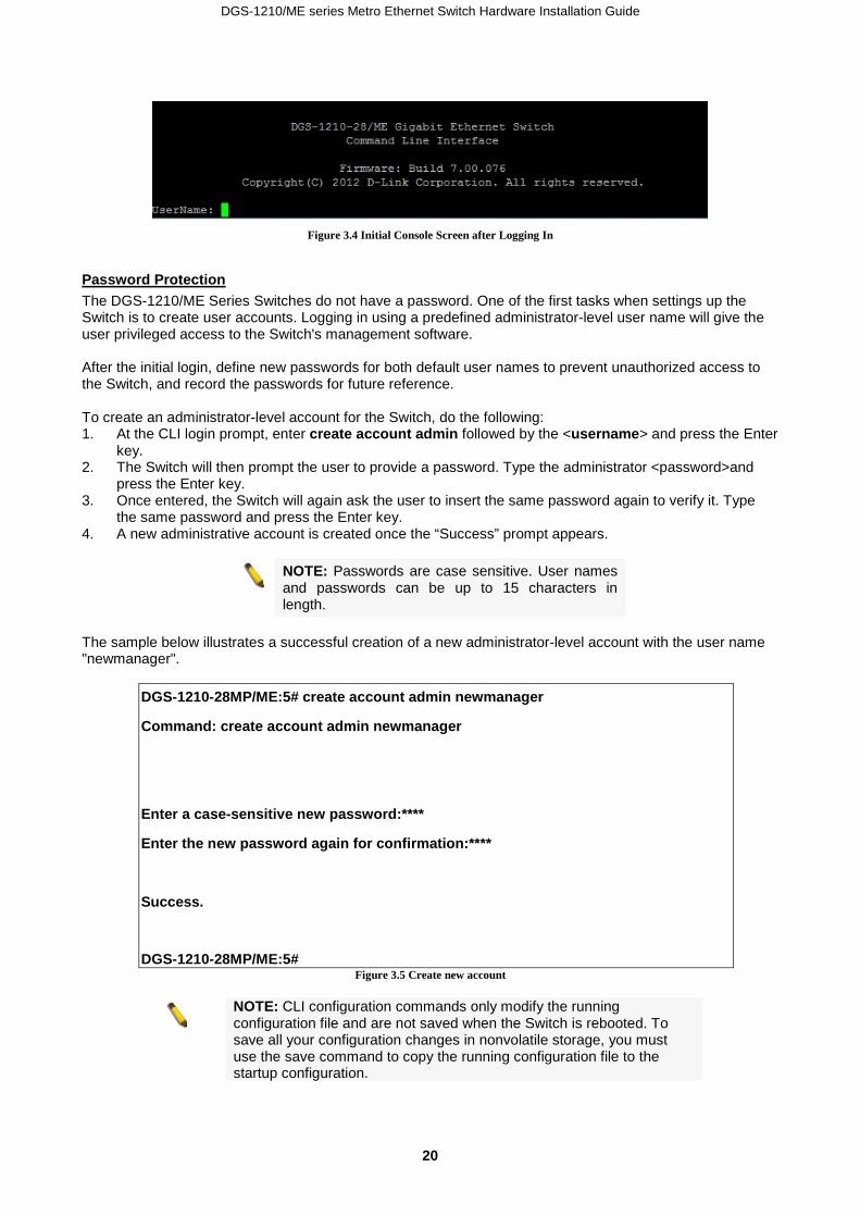
The same functions may also be accessed over a Telnet interface. Once an IP address for the Switch has been set, A Telnet program can be used (in VT-100 compatible terminal mode) to access and control the Switch. All of the screens are identical, whether accessed from the console port or from a Telnet interface. After the Switch reboots and you have to logged in, the console looks like this:
DGS-1210/ME series Metro Ethernet Switch Hardware Installation Guide
20
Figure 3.4 Initial Console Screen after Logging In
Password Protection The DGS-1210/ME Series Switches do not have a password. One of the first tasks when settings up the Switch is to create user accounts. Logging in using a predefined administrator-level user name will give the user privileged access to the Switch's management software. After the initial login, define new passwords for both default user names to prevent unauthorized access to the Switch, and record the passwords for future reference. To create an administrator-level account for the Switch, do the following: 1. At the CLI login prompt, enter create account admin followed by the <username> and press the Enter
key. 2. The Switch will then prompt the user to provide a password. Type the administrator <password>and
press the Enter key. 3. Once entered, the Switch will again ask the user to insert the same password again to verify it. Type
the same password and press the Enter key. 4. A new administrative account is created once the “Success” prompt appears.
NOTE: Passwords are case sensitive. User names and passwords can be up to 15 characters in length.
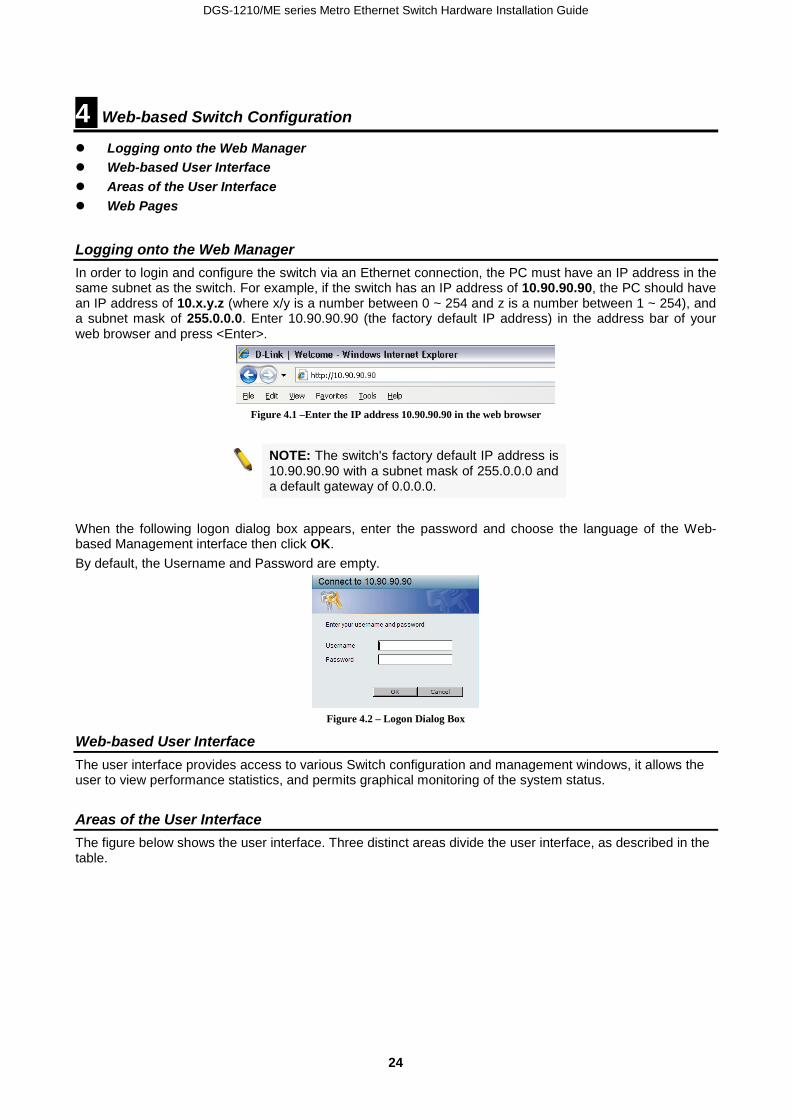
The sample below illustrates a successful creation of a new administrator-level account with the user name "newmanager".
DGS-1210-28MP/ME:5# create account admin newmanager
Command: create account admin newmanager
Enter a case-sensitive new password:****
Enter the new password again for confirmation:****
Success.
DGS-1210-28MP/ME:5# Figure 3.5 Create new account
NOTE: CLI configuration commands only modify the running configuration file and are not saved when the Switch is rebooted. To save all your configuration changes in nonvolatile storage, you must use the save command to copy the running configuration file to the startup configuration.

DGS-1210/ME series Metro Ethernet Switch Hardware Installation Guide
2211
Assigning IP Addresses Each Switch must be assigned its own IP Address, which is used for communication with an SNMP network manager or other TCP/IP application (for example BOOTP, TFTP). The Switch's default IP address is 10.90.90.90. You can change the default Switch IP address to meet the specification of your networking address scheme. The Switch is also assigned a unique MAC address by the factory. This MAC address cannot be changed, and can be found by entering the command show switch into the command line interface, as shown below.
DGS-1210-28MP/ME:5# show switch
Command: show switch
Device Type : DGS-1210-28MP/ME
MAC Address : 00-01-02-03-04-05
IP Address : 10.90.90.90 (Manual)
VLAN Name : default
Subnet Mask : 255.0.0.0
Default Gateway : 0.0.0.0
System Boot Version : 1.01.033
System Firmware Version : 7.01.B030
System Hardware Version : B1
System Serial Number : QBDGS12102800
System Name :
System Location :
System up time : 0 days, 0 hrs, 1 min, 2 secs
System Contact :
System Time : 12/08/2016 15:26:11
RTC Time : 12/08/2016 15:26:11
STP : Disabled
GVRP : Disabled
IGMP Snooping : Disabled
VLAN Trunk : Disabled
802.1X Status : Disabled
DGS-1210-28MP/ME:5#
Figure 3.6 Show switch command
The Switch's MAC address can also be found from the Web management program on the System Information window in the Configuration folder. The IP address for the Switch must be set before it can be managed with the Web-based manager. The Switch IP address can be automatically set using BOOTP or DHCP protocols, in which case the actual address assigned to the Switch must be known.

DGS-1210/ME series Metro Ethernet Switch Hardware Installation Guide
22
The IP address may be set using the Command Line Interface (CLI) over the console serial port as follows: Starting at the command line prompt, enter the commands config ipif System ipaddress xxx.xxx.xxx.xxx/yyy.yyy.yyy.yyy Where the x's represent the IP address to be assigned to the IP interface named System and the y's represent the corresponding subnet mask. Alternatively, you can enter config ipif System ipaddress xxx.xxx.xxx.xxx/z. Where the x's represent the IP address to be assigned to the IP interface named System and the z represents the corresponding number of subnets in CIDR notation. The IP interface named System on the Switch can be assigned an IP address and subnet mask, and then be used to connect a management station to the Switch's Telnet or Web-based management agent.
DGS-1210-28MP/ME:5# config ipif System ipaddress 10.90.90.91/255.0.0.0
Command: config ipif System ipaddress 10.90.90.91/255.0.0.0
Success.
DGS-1210-28MP/ME:5# Figure 3.7 Assigning the Switch an IP address
In the above example, the Switch was assigned an IP address of 10.90.90.91 with a subnet mask of 255.0.0.0. (the CIDR form was used to set the address (10.90.90.91/8). The system message Success indicates that the command was executed successfully. The Switch can now be configured and managed via Telnet and the CLI or via the Web-based management. SNMP Settings Each Switch must be assigned its own IP Address, which is used for communication with an SNMP network manager Simple Network Management Protocol (SNMP) is an OSI Layer 7 (Application Layer) designed specifically for managing and monitoring network devices. SNMP enables network management stations to read and modify the settings of gateways, routers, switches and other network devices. Use SNMP to configure system features for proper operation, monitor performance and detect potential problems in the Switch, switch group or network. Managed devices that support SNMP include software (referred to as an agent), which runs locally on the device. A defined set of variables (managed objects) is maintained by the SNMP agent and used to manage the device. These objects are defined in a Management Information Base (MIB), which provides a standard presentation of the information controlled by the on-board SNMP agent. SNMP defines both the format of the MIB specifications and the protocol used to access this information over the network. The Switch supports SNMP versions 1, 2c, and 3. The administrator may specify which SNMP version to use to monitor and control the Switch. The three SNMP versions vary in the level of security provided between the management station and the network device. In SNMP v1 and v2, user authentication is accomplished using 'community strings', which function like passwords. The remote user SNMP application and the Switch SNMP must use the same community string. SNMP packets from any station that has not been authenticated are ignored (dropped). The default community strings for the Switch used for SNMP v1 and v2 management access are:
• public - Allows authorized management stations to retrieve MIB objects. • private - Allows authorized management stations to retrieve and modify MIB objects.
SNMP v3 uses a more sophisticated authentication process that is separated into two parts. The first part is to maintain a list of users and their attributes that are allowed to act as SNMP managers. The second part

DGS-1210/ME series Metro Ethernet Switch Hardware Installation Guide
2233
describes what each user on that list can do as an SNMP manager. The Switch allows groups of users to be listed and configured with a shared set of privileges. The SNMP version may also be set for a listed group of SNMP managers. Thus, a group of SNMP managers can be created to view read-only information or receive traps using SNMP v1 while assigning a higher level of security to another group, granting read/write privileges using SNMP v3. Using SNMP v3 individual users or groups of SNMP managers can be allowed to perform or be restricted from performing specific SNMP management functions. The functions allowed or restricted are defined using the Object Identifier (OID) associated with a specific MIB. An additional layer of security is available for SNMP v3 in that SNMP messages may be encrypted. To read more about how to configure SNMP v3 settings for the Switch read the section entitled Management. Traps Traps are messages that alert network personnel of events that occur on the Switch. The events can be as serious as a reboot (someone accidentally turned OFF the Switch), or less serious like a port status change. The Switch generates traps and sends them to the trap recipient (or network manager). Typical traps include trap messages for Authentication Failure, Topology Change and Broadcast\Multicast Storm. Management Information Base (MIB) The Switch in the Management Information Base (MIB) stores management and counter information. The Switch uses the standard MIB-II Management Information Base module. Consequently, values for MIB objects can be retrieved from any SNMP-based network management software. In addition to the standard MIB-II, the Switch also supports its own proprietary enterprise MIB as an extended Management Information Base. The proprietary MIB may also be retrieved by specifying the MIB Object Identifier. MIB values can be either read-only or read-write.
DGS-1210/ME series Metro Ethernet Switch Hardware Installation Guide
24
4 Web-based Switch Configuration
Logging onto the Web Manager Web-based User Interface Areas of the User Interface Web Pages
Logging onto the Web Manager In order to login and configure the switch via an Ethernet connection, the PC must have an IP address in the same subnet as the switch. For example, if the switch has an IP address of 10.90.90.90, the PC should have an IP address of 10.x.y.z (where x/y is a number between 0 ~ 254 and z is a number between 1 ~ 254), and a subnet mask of 255.0.0.0. Enter 10.90.90.90 (the factory default IP address) in the address bar of your web browser and press <Enter>.
Figure 4.1 –Enter the IP address 10.90.90.90 in the web browser
NOTE: The switch's factory default IP address is 10.90.90.90 with a subnet mask of 255.0.0.0 and a default gateway of 0.0.0.0.
When the following logon dialog box appears, enter the password and choose the language of the Web-based Management interface then click OK. By default, the Username and Password are empty.
Figure 4.2 – Logon Dialog Box
Web-based User Interface The user interface provides access to various Switch configuration and management windows, it allows the user to view performance statistics, and permits graphical monitoring of the system status.
Areas of the User Interface The figure below shows the user interface. Three distinct areas divide the user interface, as described in the table.
DGS-1210/ME series Metro Ethernet Switch Hardware Installation Guide
2255
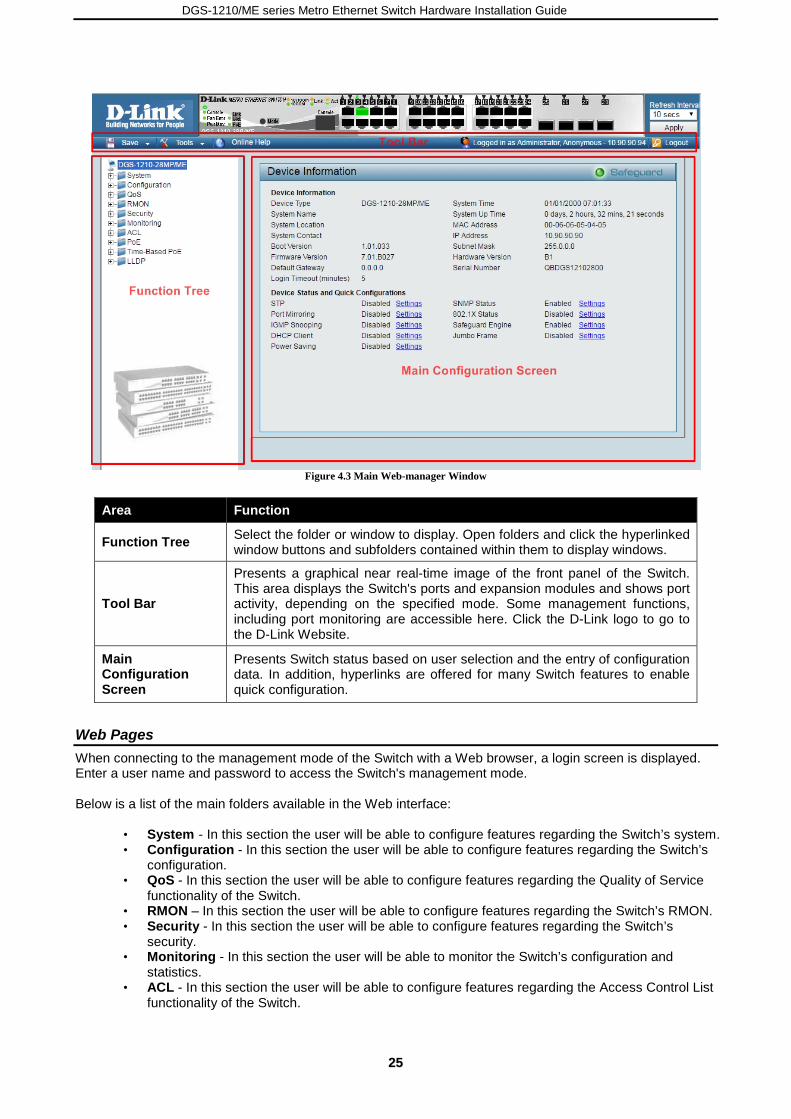
Figure 4.3 Main Web-manager Window
Area Function
Function Tree Select the folder or window to display. Open folders and click the hyperlinked window buttons and subfolders contained within them to display windows.
Tool Bar
Presents a graphical near real-time image of the front panel of the Switch. This area displays the Switch's ports and expansion modules and shows port activity, depending on the specified mode. Some management functions, including port monitoring are accessible here. Click the D-Link logo to go to the D-Link Website.
Main Configuration Screen
Presents Switch status based on user selection and the entry of configuration data. In addition, hyperlinks are offered for many Switch features to enable quick configuration.
Web Pages When connecting to the management mode of the Switch with a Web browser, a login screen is displayed. Enter a user name and password to access the Switch's management mode. Below is a list of the main folders available in the Web interface: AREA 2AREA
• System - In this section the user will be able to configure features regarding the Switch’s system. • Configuration - In this section the user will be able to configure features regarding the Switch’s
configuration. • QoS - In this section the user will be able to configure features regarding the Quality of Service
functionality of the Switch. • RMON – In this section the user will be able to configure features regarding the Switch’s RMON. • Security - In this section the user will be able to configure features regarding the Switch’s
security. • Monitoring - In this section the user will be able to monitor the Switch’s configuration and
statistics. • ACL - In this section the user will be able to configure features regarding the Access Control List
functionality of the Switch.

DGS-1210/ME series Metro Ethernet Switch Hardware Installation Guide
26
PoE – In this section the user will be able to configure features regarding the Power over Ethernet functionality of the Switch.
• Time-Based PoE – In this section the user will be able to configure features regarding the Time-Based PoE of Power over Ethernet functionality of the Switch.
• LLDP - In this section the user will be able to configure features regarding the LLDP functionality of the Switch.
DGS-1210/ME series Metro Ethernet Switch Hardware Installation Guide
2277
Appendix A – Ethernet Technology
The appendix contains the device specifications, and contains the topics: • Technical Specifications • Supported Transceivers
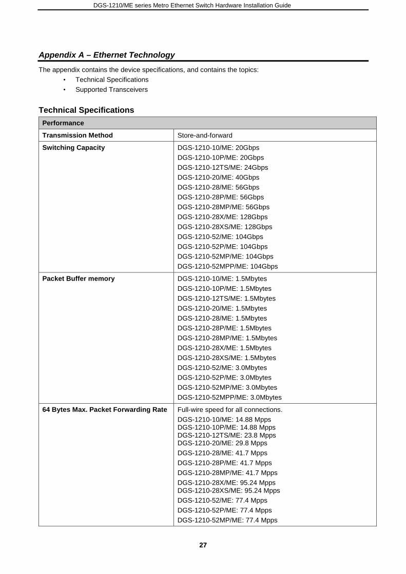
Technical Specifications Performance
Transmission Method Store-and-forward
Switching Capacity DGS-1210-10/ME: 20Gbps DGS-1210-10P/ME: 20Gbps DGS-1210-12TS/ME: 24Gbps DGS-1210-20/ME: 40Gbps DGS-1210-28/ME: 56Gbps DGS-1210-28P/ME: 56Gbps DGS-1210-28MP/ME: 56Gbps DGS-1210-28X/ME: 128Gbps DGS-1210-28XS/ME: 128Gbps DGS-1210-52/ME: 104Gbps DGS-1210-52P/ME: 104Gbps DGS-1210-52MP/ME: 104Gbps DGS-1210-52MPP/ME: 104Gbps
Packet Buffer memory DGS-1210-10/ME: 1.5Mbytes DGS-1210-10P/ME: 1.5Mbytes DGS-1210-12TS/ME: 1.5Mbytes DGS-1210-20/ME: 1.5Mbytes DGS-1210-28/ME: 1.5Mbytes DGS-1210-28P/ME: 1.5Mbytes DGS-1210-28MP/ME: 1.5Mbytes DGS-1210-28X/ME: 1.5Mbytes DGS-1210-28XS/ME: 1.5Mbytes DGS-1210-52/ME: 3.0Mbytes DGS-1210-52P/ME: 3.0Mbytes DGS-1210-52MP/ME: 3.0Mbytes DGS-1210-52MPP/ME: 3.0Mbytes
64 Bytes Max. Packet Forwarding Rate Full-wire speed for all connections. DGS-1210-10/ME: 14.88 Mpps DGS-1210-10P/ME: 14.88 Mpps DGS-1210-12TS/ME: 23.8 Mpps DGS-1210-20/ME: 29.8 Mpps DGS-1210-28/ME: 41.7 Mpps DGS-1210-28P/ME: 41.7 Mpps DGS-1210-28MP/ME: 41.7 Mpps DGS-1210-28X/ME: 95.24 Mpps DGS-1210-28XS/ME: 95.24 Mpps DGS-1210-52/ME: 77.4 Mpps DGS-1210-52P/ME: 77.4 Mpps DGS-1210-52MP/ME: 77.4 Mpps

DGS-1210/ME series Metro Ethernet Switch Hardware Installation Guide
28
Performance DGS-1210-52MPP/ME: 77.4 Mpps
MAC Address Learning Automatic update. Supports 16K MAC address.
DRAM 256 MB – DDR3
Flash Memory 32 MB – SPI flash
Priority Queues 8 Priority Queues per port.
Forwarding Table Age Time Max age: 10–600 seconds. Default = 300.
Physical and Environmental
AC Inputs DGS-1210-10/ME: AC Input: 100 – 240 VAC, 50-60 Hz, Max. 0.3A DGS-1210-10P/ME: AC Input: 100 – 240 VAC, 50-60 Hz, Max. 1.3A DGS-1210-12TS/ME: AC Input: 100 – 240 VAC, 50-60 Hz, Max. 0.4A DGS-1210-20/ME: AC Input: 100 – 240 VAC, 50-60 Hz, Max. 0.33A DGS-1210-28/ME: AC Input: 100 – 240 VAC, 50-60 Hz, Max. 0.43A DGS-1210-28P/ME: AC Input: 100 – 240 VAC, 50-60 Hz, Max. 3.05A DGS-1210-28MP/ME: AC Input: 100 – 240 VAC, 50-60 Hz, Max. 5.48A DGS-1210-28X/ME: AC Input: 100 – 240 VAC, 50-60 Hz, Max. 0.58A DGS-1210-28XS/ME: AC Input: 100 – 240 VAC, 50-60 Hz, Max. 0.98A DGS-1210-52/ME: AC Input: 100 – 240 VAC, 50-60 Hz, Max. 0.7A DGS-1210-52P/ME: AC Input: 100 – 240 VAC, 50-60 Hz, Max. 3.36A DGS-1210-52MP/ME: AC Input: 100 – 240 VAC, 50-60 Hz, Max. 5.78A DGS-1210-52MPP/ME: AC Input: 100 – 240 VAC, 50-60 Hz, Max. 10A

DGS-1210/ME series Metro Ethernet Switch Hardware Installation Guide
2299
Physical and Environmental
Power Consumption DGS-1210-10/ME: Maximum power consumption: 13.59Watts Standby power consumption: 9.4Watts DGS-1210-10P/ME: Maximum power consumption: 103.4Watts (PoE on), 17.9Watts (PoE off) Standby power consumption: 11.1Watts DGS-1210-12TS/ME: Maximum power consumption: 13.85Watts Standby power consumption: 7.49Watts DGS-1210-20/ME: Maximum power consumption: 13.97Watts Standby power consumption: 6.95Watts DGS-1210-28/ME: Maximum power consumption: 19.14Watts Standby power consumption: 8.21Watts DGS-1210-28P/ME: Maximum power consumption: 251.5Watts (PoE on), 28.7Watts (PoE off) Standby power consumption: 18.4Watts DGS-1210-28MP/ME: Maximum power consumption: 455Watts (PoE on), 35.6Watts (PoE off) Standby power consumption: 23.5Watts DGS-1210-28X/ME: Maximum power consumption: 24.5Watts Standby power consumption: 13Watts DGS-1210-28XS/ME: Maximum power consumption: 33.4Watts Standby power consumption: 16.7Watts DGS-1210-52/ME : Maximum power consumption: 38.85Watts Standby power consumption: 21.72Watts DGS-1210-52P/ME: Maximum power consumption: 273.2Watts (PoE on), 47.9Watts (PoE off) Standby power consumption: 32Watts DGS-1210-52MP/ME:
DGS-1210/ME series Metro Ethernet Switch Hardware Installation Guide
30
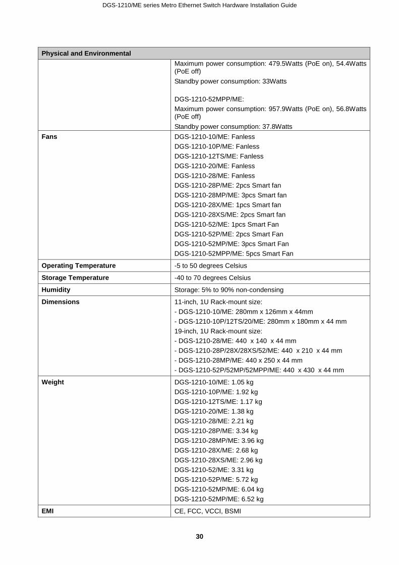
Physical and Environmental Maximum power consumption: 479.5Watts (PoE on), 54.4Watts (PoE off) Standby power consumption: 33Watts DGS-1210-52MPP/ME: Maximum power consumption: 957.9Watts (PoE on), 56.8Watts (PoE off) Standby power consumption: 37.8Watts
Fans DGS-1210-10/ME: Fanless DGS-1210-10P/ME: Fanless DGS-1210-12TS/ME: Fanless DGS-1210-20/ME: Fanless DGS-1210-28/ME: Fanless DGS-1210-28P/ME: 2pcs Smart fan DGS-1210-28MP/ME: 3pcs Smart fan DGS-1210-28X/ME: 1pcs Smart fan DGS-1210-28XS/ME: 2pcs Smart fan DGS-1210-52/ME: 1pcs Smart Fan DGS-1210-52P/ME: 2pcs Smart Fan DGS-1210-52MP/ME: 3pcs Smart Fan DGS-1210-52MPP/ME: 5pcs Smart Fan
Operating Temperature -5 to 50 degrees Celsius
Storage Temperature -40 to 70 degrees Celsius
Humidity Storage: 5% to 90% non-condensing
Dimensions 11-inch, 1U Rack-mount size: - DGS-1210-10/ME: 280mm x 126mm x 44mm - DGS-1210-10P/12TS/20/ME: 280mm x 180mm x 44 mm 19-inch, 1U Rack-mount size: - DGS-1210-28/ME: 440 x 140 x 44 mm - DGS-1210-28P/28X/28XS/52/ME: 440 x 210 x 44 mm - DGS-1210-28MP/ME: 440 x 250 x 44 mm - DGS-1210-52P/52MP/52MPP/ME: 440 x 430 x 44 mm
Weight DGS-1210-10/ME: 1.05 kg DGS-1210-10P/ME: 1.92 kg DGS-1210-12TS/ME: 1.17 kg DGS-1210-20/ME: 1.38 kg DGS-1210-28/ME: 2.21 kg DGS-1210-28P/ME: 3.34 kg DGS-1210-28MP/ME: 3.96 kg DGS-1210-28X/ME: 2.68 kg DGS-1210-28XS/ME: 2.96 kg DGS-1210-52/ME: 3.31 kg DGS-1210-52P/ME: 5.72 kg DGS-1210-52MP/ME: 6.04 kg DGS-1210-52MP/ME: 6.52 kg
EMI CE, FCC, VCCI, BSMI

DGS-1210/ME series Metro Ethernet Switch Hardware Installation Guide
3311
Physical and Environmental CE (DGS-1210-28X/ME, 28XS/ME only)
Safety UL, CB, LVD, BSMI UL, CB, LVD (DGS-1210-28X/ME, 28XS/ME only)
General
Number of Ports: DGS-1210-10/ME: 8-Ports 10/100/1000Mbps + 2-Ports 1000Mbps SFP DGS-1210-10P/ME: 8-Ports PoE 10/100/1000Mbps + 2-Ports 1000Mbps SFP DGS-1210-12TS/ME: 10-Ports 1000Mbps SFP + 2-Ports 10/100/1000Mbps DGS-1210-20/ME: 16-Ports 10/100/1000Mbps + 4-Ports 1000Mbps SFP DGS-1210-28/ME: 24-Ports 10/100/1000Mbps + 4-Ports 1000Mbps SFP DGS-1210-28P/ME: 24-Ports PoE 10/100/1000Mbps + 4-Ports 1000Mbps SFP DGS-1210-28MP/ME: 24-Ports PoE 10/100/1000Mbps + 4-Ports 1000Mbps SFP DGS-1210-28X/ME: 24-Ports 10/100/1000Mbps + 4-Ports 10G SFP+ DGS-1210-28XS/ME: 24-Ports 100/1000Mbps SFP + 4-Ports 10G SFP+ DGS-1210-52/ME: 48-Ports 10/100/1000Mbps + 4-Ports 1000Mbps SFP DGS-1210-52P/ME: 48-Ports 10/100/1000Mbps with 24-Ports PoE 10/100/1000Mbps + 4-Ports 1000Mbps SFP DGS-1210-52MP/ME: 48-Ports PoE 10/100/1000Mbps + 4-Ports 1000Mbps SFP DGS-1210-52MPP/ME: 48-Ports PoE 10/100/1000Mbps + 4-Ports 1000Mbps SFP
DGS-1210/ME series Metro Ethernet Switch Hardware Installation Guide
32
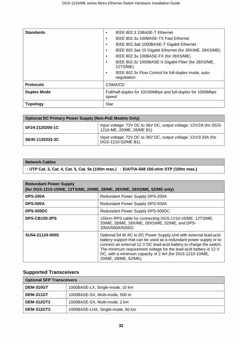
Standards • IEEE 802.3 10BASE-T Ethernet • IEEE 802.3u 100BASE-TX Fast Ethernet • IEEE 802.3ab 1000BASE-T Gigabit Ethernet • IEEE 802.3ae 10 Gigabit Ethernet (for 28X/ME, 28XS/ME) • IEEE 802.3u 100BASE-FX (for 28XS/ME) • IEEE 802.3z 1000BASE-X Gigabit Fiber (for 28XS/ME,
12TS/ME) • IEEE 802.3x Flow Control for full-duplex mode, auto-
negotiation
Protocols CSMA/CD
Duplex Mode Full/half-duplex for 10/100Mbps and full-duplex for 1000Mbps speed
Topology Star
Optional DC Primary Power Supply (Non-PoE Models Only)
SF24-2120200-1C Input voltage: 72V DC to 36V DC, output voltage: 12V/2A (for DGS-1210-ME, 20/ME, 28/ME B1)
SE40-1120333-3C Input voltage: 72V DC to 36V DC, output voltage: 12V/3.33A (for DGS-1210-52/ME B1)
Network Cables
・UTP Cat. 3, Cat. 4, Cat. 5, Cat. 5e (100m max.) ・EIA/TIA-568 150-ohm STP (100m max.)
Redundant Power Supply (for DGS-1210-10/ME, 12TS/ME, 20/ME, 28/ME, 28X/ME, 28XS/ME, 52/ME only) DPS-200A Redundant Power Supply DPS-200A
DPS-500A Redundant Power Supply DPS-500A
DPS-500DC Redundant Power Supply DPS-500DC
DPS-CB150-2PS 150cm RPS cable for connecting DGS-1210-10/ME, 12TS/ME, 20/ME, 28/ME, 28X/ME, 28XS/ME, 52/ME, and DPS-200A/500A/500DC
SU54-21124-000S Optional 54 W AC to DC Power Supply Unit with external lead-acid battery support that can be used as a redundant power supply or to connect an external 12 V DC lead-acid battery to charge the switch. The minimum requirement voltage for the lead-acid battery is 12 V DC, with a minimum capacity of 2 AH (for DGS-1210-10/ME, 20/ME, 28/ME, 52/ME).
Supported Transceivers Optional SFP Transceivers
DEM-310GT 1000BASE-LX, Single-mode, 10 km
DEM-311GT 1000BASE-SX, Multi-mode, 500 m
DEM-312GT2 1000BASE-SX, Multi-mode, 2 km
DEM-312GT2 1000BASE-LHX, Single-mode, 50 km
DGS-1210/ME series Metro Ethernet Switch Hardware Installation Guide
3333
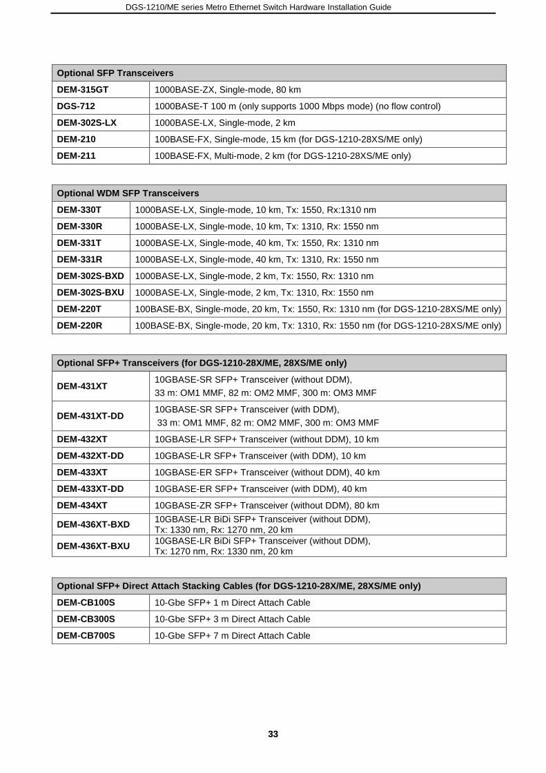
Optional SFP Transceivers
DEM-315GT 1000BASE-ZX, Single-mode, 80 km
DGS-712 1000BASE-T 100 m (only supports 1000 Mbps mode) (no flow control)
DEM-302S-LX 1000BASE-LX, Single-mode, 2 km
DEM-210 100BASE-FX, Single-mode, 15 km (for DGS-1210-28XS/ME only)
DEM-211 100BASE-FX, Multi-mode, 2 km (for DGS-1210-28XS/ME only)
Optional WDM SFP Transceivers
DEM-330T 1000BASE-LX, Single-mode, 10 km, Tx: 1550, Rx:1310 nm
DEM-330R 1000BASE-LX, Single-mode, 10 km, Tx: 1310, Rx: 1550 nm
DEM-331T 1000BASE-LX, Single-mode, 40 km, Tx: 1550, Rx: 1310 nm
DEM-331R 1000BASE-LX, Single-mode, 40 km, Tx: 1310, Rx: 1550 nm
DEM-302S-BXD 1000BASE-LX, Single-mode, 2 km, Tx: 1550, Rx: 1310 nm
DEM-302S-BXU 1000BASE-LX, Single-mode, 2 km, Tx: 1310, Rx: 1550 nm
DEM-220T 100BASE-BX, Single-mode, 20 km, Tx: 1550, Rx: 1310 nm (for DGS-1210-28XS/ME only)
DEM-220R 100BASE-BX, Single-mode, 20 km, Tx: 1310, Rx: 1550 nm (for DGS-1210-28XS/ME only)
Optional SFP+ Transceivers (for DGS-1210-28X/ME, 28XS/ME only)
DEM-431XT 10GBASE-SR SFP+ Transceiver (without DDM), 33 m: OM1 MMF, 82 m: OM2 MMF, 300 m: OM3 MMF
DEM-431XT-DD 10GBASE-SR SFP+ Transceiver (with DDM), 33 m: OM1 MMF, 82 m: OM2 MMF, 300 m: OM3 MMF
DEM-432XT 10GBASE-LR SFP+ Transceiver (without DDM), 10 km
DEM-432XT-DD 10GBASE-LR SFP+ Transceiver (with DDM), 10 km
DEM-433XT 10GBASE-ER SFP+ Transceiver (without DDM), 40 km
DEM-433XT-DD 10GBASE-ER SFP+ Transceiver (with DDM), 40 km
DEM-434XT 10GBASE-ZR SFP+ Transceiver (without DDM), 80 km
DEM-436XT-BXD 10GBASE-LR BiDi SFP+ Transceiver (without DDM), Tx: 1330 nm, Rx: 1270 nm, 20 km
DEM-436XT-BXU 10GBASE-LR BiDi SFP+ Transceiver (without DDM), Tx: 1270 nm, Rx: 1330 nm, 20 km
Optional SFP+ Direct Attach Stacking Cables (for DGS-1210-28X/ME, 28XS/ME only)
DEM-CB100S 10-Gbe SFP+ 1 m Direct Attach Cable
DEM-CB300S 10-Gbe SFP+ 3 m Direct Attach Cable
DEM-CB700S 10-Gbe SFP+ 7 m Direct Attach Cable

DGS-1210/ME series Metro Ethernet Switch Hardware Installation Guide
34
Appendix B – Cables and Connectors
Ethernet Cable: When connecting the Switch to another switch, a bridge or hub, a normal cable is necessary. Please review these products for matching cable pin assignment. The following diagrams and tables show the standard RJ-45 receptacle/connector and their pin assignments.
Figure D- 1. The standard RJ-45 port and connector
RJ-45 Pin Assignments
Contact MDI-X Port MDI-II Port
1 RD+ (receive) TD+ (transmit)
2 RD- (receive) TD- (transmit)
3 TD+ (transmit) RD+ (receive)
4 1000BASE-T 1000BASE-T
5 1000BASE-T 1000BASE-T
6 TD- (transmit) RD- (receive)
7 1000BASE-T 1000BASE-T
8 1000BASE-T 1000BASE-T
Console Cable: When connecting the Switch a PC, a Console cable is necessary. The following diagrams and tables show the standard Console-to-DJ-45 receptacle/connector and their pin assignments.
Figure B- 2. Console-to-RJ-45 Cable
Console-RJ-45 Pin Assignments
Pin Console (DB9/RS232) RJ-45
1 Not Used Not Used
2 RXD Not Used
3 TXD TXD

DGS-1210/ME series Metro Ethernet Switch Hardware Installation Guide
3355
4 Not Used GND
5 GND (shared) GND
6 Not Used RXD
7 Not Used Not Used
8 Not Used Not Used
DGS-1210/ME series Metro Ethernet Switch Hardware Installation Guide
36
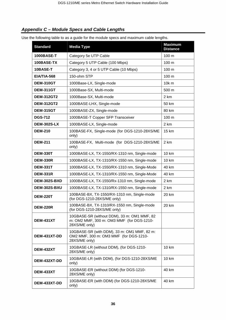
Appendix C – Module Specs and Cable Lengths
Use the following table to as a guide for the module specs and maximum cable lengths.
Standard Media Type Maximum Distance
1000BASE-T Category 5e UTP Cable 100 m
100BASE-TX Category 5 UTP Cable (100 Mbps) 100 m
10BASE-T Category 3, 4 or 5 UTP Cable (10 Mbps) 100 m
EIA/TIA-568 150-ohm STP 100 m
DEM-310GT 1000Base-LX, Single-mode 10k m
DEM-311GT 1000Base-SX, Multi-mode 500 m
DEM-312GT2 1000Base-SX, Multi-mode 2 km
DEM-312GT2 1000BASE-LHX, Single-mode 50 km
DEM-315GT 1000BASE-ZX, Single-mode 80 km
DGS-712 1000BASE-T Copper SFP Transceiver 100 m
DEM-302S-LX 1000BASE-LX, Single-mode 2 km
DEM-210 100BASE-FX, Single-mode (for DGS-1210-28XS/ME only)
15 km
DEM-211 100BASE-FX, Multi-mode (for DGS-1210-28XS/ME only)
2 km
DEM-330T 1000BASE-LX, TX-1550/RX-1310 nm, Single-mode 10 km
DEM-330R 1000BASE-LX, TX-1310/RX-1550 nm, Single-mode 10 km
DEM-331T 1000BASE-LX, TX-1550/RX-1310 nm, Single-Mode 40 km
DEM-331R 1000BASE-LX, TX-1310/RX-1550 nm, Single-Mode 40 km
DEM-302S-BXD 1000BASE-LX, TX-1550/Rx-1310 nm, Single-mode 2 km
DEM-302S-BXU 1000BASE-LX, TX-1310/RX-1550 nm, Single-mode 2 km
DEM-220T 100BASE-BX, TX-1550/RX-1310 nm, Single-mode (for DGS-1210-28XS/ME only)
20 km
DEM-220R 100BASE-BX, TX-1310/RX-1550 nm, Single-mode (for DGS-1210-28XS/ME only)
20 km
DEM-431XT 10GBASE-SR (without DDM), 33 m: OM1 MMF, 82 m: OM2 MMF, 300 m: OM3 MMF (for DGS-1210-28XS/ME only)
DEM-431XT-DD 10GBASE-SR (with DDM), 33 m: OM1 MMF, 82 m: OM2 MMF, 300 m: OM3 MMF (for DGS-1210-28XS/ME only)
DEM-432XT 10GBASE-LR (without DDM), (for DGS-1210-28XS/ME only)
10 km
DEM-432XT-DD 10GBASE-LR (with DDM), (for DGS-1210-28XS/ME only)
10 km
DEM-433XT 10GBASE-ER (without DDM) (for DGS-1210-28XS/ME only)
40 km
DEM-433XT-DD 10GBASE-ER (with DDM) (for DGS-1210-28XS/ME only)
40 km

DGS-1210/ME series Metro Ethernet Switch Hardware Installation Guide
3377
DEM-434XT 10GBASE-ZR (without DDM) (for DGS-1210-28XS/ME only)
80 km
DEM-436XT-BXD 10GBASE-LR BiDi (without DDM), TX-1330/RX-1270 nm (for DGS-1210-28XS/ME only)
20 km
DEM-436XT-BXU 10GBASE-LR BiDi (without DDM), TX-1270/Rx-1330 nm (for DGS-1210-28XS/ME only)
20 km
DEM-CB100S 10-Gbe SFP+ 1m Direct Attach Cable
DEM-CB300S 10-Gbe SFP+ 3m Direct Attach Cable
DEM-CB700S 10-Gbe SFP+ 7m Direct Attach Cable
Network pluggable optical modules meet the following regulatory requirements:
• Class 1 Laser Product • EN60825-1+A2:2001 or later, European laser standard • FCC 21 CFR Chapter 1, Subchapter J in accordance with FDA & CDRH requirements
Europe customers
TECHNICAL SUPPORT
dlink.com/support
TECHNISCHE UNTERSTÜTZUNG
ASSISTANCE TECHNIQUE
ASISTENCIA TÉCNICA
SUPPORTO TECNICO
TECHNISCHE ONDERSTEUNING
POMOC TECHNICZNA
TECHNICKÁ PODPORA
TECHNICKÁ PODPORA
TECHNIKAI TÁMOGATÁS
TEKNISK SUPPORT
TEKNISK SUPPORT
TEKNISK STØTTE
TEKNINEN TUKI
ASSISTÊNCIA TÉCNICA
ΤΕΧΝΙΚΉ ΥΠΟΣΤΉΡΙΞΗ
TEHNIČKA PODRŠKA
TEHNIČNA PODPORA
SUPORT TEHNIC
ТЕХНИЧЕСКА ПОДДРЪЖКА

Australia customers Tel: 1300-700-100 24/7 Technical Support Web: http://www.dlink.com.au E-mail: [email protected]
India customers Tel: +91-832-2856000 Toll Free 1800-233-0000 Web: www.dlink.co.in E-Mail: [email protected]
Singapore, Thailand, Indonesia, Malaysia, Philippines, Vietnam customers Singapore - www.dlink.com.sg Thailand - www.dlink.co.th Indonesia - www.dlink.co.id Malaysia - www.dlink.com.my Philippines - www.dlink.com.ph Vietnam - www.dlink.com.vn
Korea customers Tel : +82-2-2028-1810 Monday to Friday 9:00am to 6:00pm Web : http://d-link.co.kr E-mail : [email protected]
New Zealand customers Tel: 0800-900-900 24/7 Technical Support Web: http://www.dlink.co.nz E-mail: [email protected]

South Africa and Sub Sahara Region customers Tel: +27 12 661 2025 08600 DLINK (for South Africa only) Monday to Friday 8:30am to 9:00pm South Africa Time Web: http://www.d-link.co.za E-mail: [email protected]
D-Link Middle East - Dubai, U.A.E. customers Plot No. S31102, Jebel Ali Free Zone South, P.O.Box 18224, Dubai, U.A.E. Tel: +971-4-8809022 Fax: +971-4-8809066 / 8809069 Technical Support: +971-4-8809033 General Inquiries: [email protected] Tech Support: [email protected]
Egypt customers 1, Makram Ebeid Street - City Light Building - floor 5 Nasrcity - Cairo, Egypt Tel.: +2 02 23521593 - +2 02 23520852 Technical Support: +2 02 26738470 General Inquiries: [email protected] Tech Support: [email protected]
Kingdom of Saudi Arabia customers Office # 84 , Al Khaleej Building ( Mujamathu Al-Khaleej) Opp. King Fahd Road, Olaya Riyadh - Saudi Arabia Tel: +966 1121 70008 Technical Support: +966 1121 70009 General Inquiries: info.sa@ dlinkmea.com Tech Support: support.sa@ dlinkmea.com

Pakistan customers Islamabad Office: 61-A, Jinnah Avenue, Blue Area, Suite # 11, EBC, Saudi Pak Tower, Islamabad - Pakistan Tel.: +92-51-2800397, 2800398 Fax: +92-51-2800399 Karachi Office: D-147/1, KDA Scheme # 1, Opposite Mudassir Park, Karsaz Road, Karachi – Pakistan Phone: +92-21-34548158, 34326649 Fax: +92-21-4375727 Technical Support: +92-21-34548310, 34305069 General Inquiries: [email protected] Tech Support: [email protected]
Iran customers Unit 1, 1st Floor, Plot No 3, Pazhoheshgah (2) Alley, Ahmad Ghasir (Bokharest) St. , Shahid Beheshti (Abbas Abad) St. , Tehran, Iran. Postal Code : 1514615911 Tel: +98-21-88880918,19 General Inquiries: [email protected] Tech Support: [email protected]
Morocco customers M.I.T.C Route de Nouaceur angle RS et CT 1029 Bureau N° 312 ET 337 Casablanca , Maroc Phone : +212 663 72 73 24 Email: [email protected]
Lebanon RMA center customers Dbayeh/Lebanon PO Box:901589 Tel: +961 4 54 49 71 Ext:14 Fax: +961 4 54 49 71 Ext:12 Email: [email protected]
Bahrain customers Technical Support: +973 1 3332904
Kuwait customers Technical Support: + 965 22453939 / +965 22453949

Техническая Поддержка Обновления программного обеспечения и документация доступны на
Интернет-сайте D-Link.
D-Link предоставляет бесплатную поддержку для клиентов в течение
гарантийного срока.
Клиенты могут обратиться в группу технической поддержки D-Link по
телефону или через Интернет.
Техническая поддержка компании D-Link работает в круглосуточном
режиме ежедневно, кроме официальных праздничных дней. Звонок
бесплатный по всей России.
Техническая поддержка D-Link:
8-800-700-5465
Техническая поддержка через Интернет:
http://www.dlink.ru
e-mail: [email protected]
Импортер:
ООО “Д-Линк Трейд”
390043, г.Рязань, пр. Шабулина, д.16
Офисы Россия Москва, Графский переулок, 14 Тел. : +7 (495) 744-00-99 E-mail: [email protected] Україна Київ, вул. Межигірська, 87-А Тел.: +38 (044) 545-64-40 E-mail: [email protected] Moldova Chisinau; str.C.Negruzzi-8

Tel: +373 (22) 80-81-07 E-mail:[email protected] Беларусь Мінск, пр-т Незалежнасці, 169 Тэл.: +375 (17) 218-13-65 E-mail: [email protected] Қазақстан Алматы, Құрманғазы к-cі,143 үй Тел.: +7 (727) 378-55-90 E-mail: [email protected] Հայաստան Երևան, Դավթաշեն 3-րդ թաղամաս, 23/5 Հեռ.՝ +374 (10) 39-86-67 Էլ. փոստ՝ [email protected] Latvija Rīga, Lielirbes iela 27 Tel.: +371 (6) 761-87-03 E-mail: [email protected] Lietuva Vilnius, Žirmūnų 139-303 Tel.: +370 (5) 236-36-29 E-mail: [email protected] Eesti E-mail: [email protected] Türkiye Uphill Towers Residence A/99 Ataşehir /ISTANBUL Tel: +90 (216) 492-99-99 Email: [email protected]
ישראל 20רח' המגשימים
קרית מטלון פתח תקווה
972 (3) 921-28-86 [email protected]

Soporte Técnico Para Usuarios En Latino America Por favor revise el número telefónico del Call Center de su país en http://www.dlinkla.com/soporte/call-center
Soporte Técnico de D-Link a través de Internet Horario de atención Soporte Técnico en www.dlinkla.com e-mail: [email protected] & [email protected]

Clientes de Brasil Caso tenha dúvidas na instalação do produto, entre em contato com o Suporte Técnico D-Link. Acesse o site: www.dlink.com.br/suporte

D-Link 友訊科技 台灣分公司 技術支援資訊 如果您還有任何本使用手冊無法協助您解決的產品相關問題,台灣、香港或是
澳門用戶可至網站、電子郵件或電話等方式與D-Link技術支援工程師聯絡。
台灣D-Link免付費技術諮詢專線 台灣技術諮詢服務專線 0800-002-615 台灣手機付費電話 (02) 6600-0123#8715 台灣服務時間:週一至週五: 9:00~21:00 週六日及國定假日(不含農曆春節) 10:00~19:00 台灣網站: http://www.dlink.com.tw 台灣電子郵件: [email protected] 產品保固期限、台灣區維修據點查詢,請參考http://www.dlink.com.tw網頁說
明。
香港、澳門D-Link技術諮詢專線 香港技術諮詢服務專線 (852) 8100 8892 香港服務時間: 週一至週五: 10:00 ~ 19:00 週六: 09:00~13:00 / 週日及公眾假期休息 香港網站: http://www.dlink.com.hk 香港電子郵件: [email protected] 香港地區維修據點如下: 維修據點: 葵芳服務中心地址:新界葵涌大連排道202-210號偉倫中心一期1樓A室 灣仔服務中心地址:香港灣仔莊士敦道178號-188號華懋莊士敦廣場16樓02室 如果您是其他地區的用戶,請參考D-Link網站www.dlink.com 查詢全球各地分
公司的聯絡資訊以取得相關支援服務。

Pelanggan Indonesia Update perangkat lunak dan dokumentasi pengguna dapat diperoleh pada situs web D-Link. Dukungan Teknis untuk pelanggan: Tel: 0800-14014-97 (TOLL FREE)
Dukungan Teknis D-Link melalui Internet: Email : [email protected] Website : http://www.dlink.co.id
日本のお客様 この度は弊社製品をお買い上げいただき、誠にありがとうございます。
製品に同梱されている保証書の購入元にお問い合わせください。
中國客戶
技術支持中心電話:400-629-6688
技術支持中心郵箱:[email protected]
各地維修中心地址請登錄官方網站查詢
網址:http://www.dlink.com.cn
400電話工作時間:工作日9:00-19:00;節假日9:00-18:00

Registration Card All Countries and Regions Excluding USA
Print, type or use block letters. Your name: Mr./Ms_____________________________________________________________________________ Organization: ________________________________________________ Dept. ____________________________ Your title at organization: ________________________________________________________________________ Telephone: _______________________________________ Fax:________________________________________ Organization's full address: ______________________________________________________________________ ____________________________________________________________________________________________ Country: _____________________________________________________________________________________ Date of purchase (Month/Day/Year): _______________________________________________________________
Product Model Product Serial No. * Product installed in type of computer
* Product installed in computer serial No.
(* Applies to adapters only) Product was purchased from: Reseller's name: ______________________________________________________________________________ Telephone: _______________________________________ Answers to the following questions help us to support your product: 1. Where and how will the product primarily be used? Home Office Travel Company Business Home Business Personal Use 2. How many employees work at installation site? 1 employee 2-9 10-49 50-99 100-499 500-999 1000 or more 3. What network protocol(s) does your organization use ? XNS/IPX TCP/IP DECnet Others_____________________________ 4. What network operating system(s) does your organization use ? D-Link LANsmart Novell NetWare NetWare Lite SCO Unix/Xenix PC NFS 3Com 3+Open Cisco Network Banyan Vines DECnet Pathwork Windows NT Windows 98 Windows 2000/ME Windows XP Others__________________________________________ 5. What network management program does your organization use ? D-View HP OpenView/Windows HP OpenView/Unix SunNet Manager Novell NMS NetView 6000 Others________________________________________ 6. What network medium/media does your organization use ? Fiber-optics Thick coax Ethernet Thin coax Ethernet 10BASE-T UTP/STP 100BASE-TX 1000BASE-T Wireless 802.11b and 802.11g wireless 802.11a Others_________________ 7. What applications are used on your network? Desktop publishing Spreadsheet Word processing CAD/CAM Database management Accounting Others_____________________ 8. What category best describes your company? Aerospace Engineering Education Finance Hospital Legal Insurance/Real Estate Manufacturing Retail/Chain store/Wholesale Government Transportation/Utilities/Communication VAR System house/company Other________________________________ 9. Would you recommend your D-Link product to a friend? Yes No Don't know yet 10.Your comments on this product? __________________________________________________________________________________________ __________________________________________________________________________________________