Hall
30
Department of Civil Engineering, N-W.F.P UET, Peshawar Hall Design (Option 1) Prof Dr. Qaisar Ali (http://www.eec.edu.pk) Page 1 of 30 90' 60' BRICK MASONRY WALL Example 1(a): Design slab and beams of a 90′ × 60′ Hall. The height of Hall is 20′. Concrete compressive strength (f c ′) = 3 ksi. Steel yield strength (f y ) = 40 ksi. Figure 1: 90′ × 60′ Hall.
-
Upload
muhammad-faheem -
Category
Documents
-
view
99 -
download
1
Transcript of Hall
Department of Civil Engineering, N-W.F.P UET, Peshawar Hall Design (Option 1)
Prof Dr. Qaisar Ali (http://www.eec.edu.pk) Page 1 of 30
90'
60'
BRICK MASONRYWALL
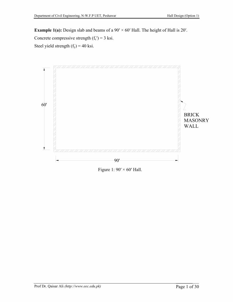
Example 1(a): Design slab and beams of a 90′ × 60′ Hall. The height of Hall is 20′.
Concrete compressive strength (fc′) = 3 ksi.
Steel yield strength (fy) = 40 ksi.
Figure 1: 90′ × 60′ Hall.
Department of Civil Engineering, N-W.F.P UET, Peshawar Hall Design (Option 1)
Prof Dr. Qaisar Ali (http://www.eec.edu.pk) Page 2 of 30
90'
60'
10' 10'
18" BRICK MASONRYWALL
BEAM
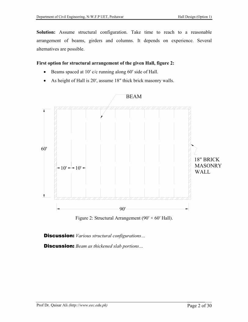
Solution: Assume structural configuration. Take time to reach to a reasonable
arrangement of beams, girders and columns. It depends on experience. Several
alternatives are possible.
First option for structural arrangement of the given Hall, figure 2:
• Beams spaced at 10′ c/c running along 60′ side of Hall.
• As height of Hall is 20′, assume 18″ thick brick masonry walls.
Figure 2: Structural Arrangement (90′ × 60′ Hall).
Discussion: Various structural configurations…
Discussion: Beam as thickened slab portions…
Department of Civil Engineering, N-W.F.P UET, Peshawar Hall Design (Option 1)
Prof Dr. Qaisar Ali (http://www.eec.edu.pk) Page 3 of 30
10.75'
l = 10 - b /2= 9.25'
b = 18" (assumed)
n w
w
10'
l = 10 - 2*(b /2) = 8.5'n w
Slab
Beam
(1) SLAB DESIGN:
Step No 1: Sizes.
• Minimum thickness of continuous one way slab as given under ACI 9.5.2,
table 9.5 (a) is:
Table 2.1: ACI formulae for continuous one way slab thickness, ACI 9.5.2
Case Slab thickness (in) End span (one end continuous) l/24
Interior span (both ends continuous) l/28 (i) l = Span length in inches. (ii)For fy other than 60,000 psi, the values from above formulae shall be multiplied by
(0.4 + fy/100000). Span length “l” of slab is defined in ACI 8.7
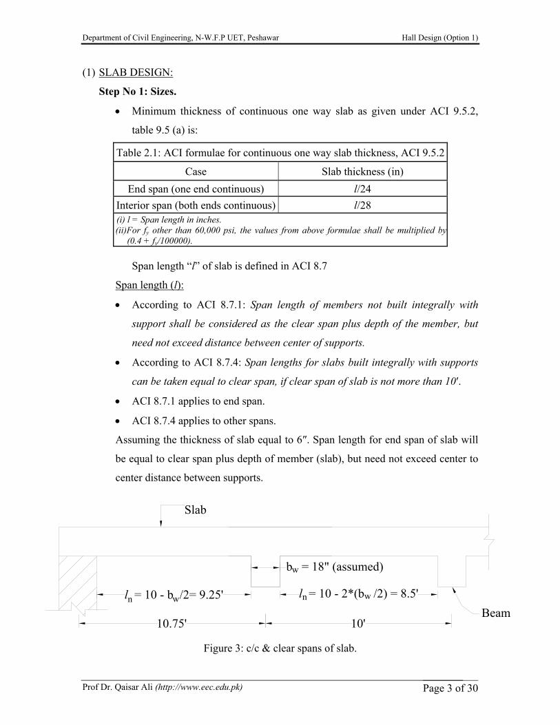
Span length (l):
• According to ACI 8.7.1: Span length of members not built integrally with
support shall be considered as the clear span plus depth of the member, but
need not exceed distance between center of supports.
• According to ACI 8.7.4: Span lengths for slabs built integrally with supports
can be taken equal to clear span, if clear span of slab is not more than 10′.
• ACI 8.7.1 applies to end span.
• ACI 8.7.4 applies to other spans.
Assuming the thickness of slab equal to 6″. Span length for end span of slab will
be equal to clear span plus depth of member (slab), but need not exceed center to
center distance between supports.
Figure 3: c/c & clear spans of slab.
Department of Civil Engineering, N-W.F.P UET, Peshawar Hall Design (Option 1)
Prof Dr. Qaisar Ali (http://www.eec.edu.pk) Page 4 of 30
10' Beam
Mainsteel
reinforcement
Shrinkage reinforcementSlab
6" 5"
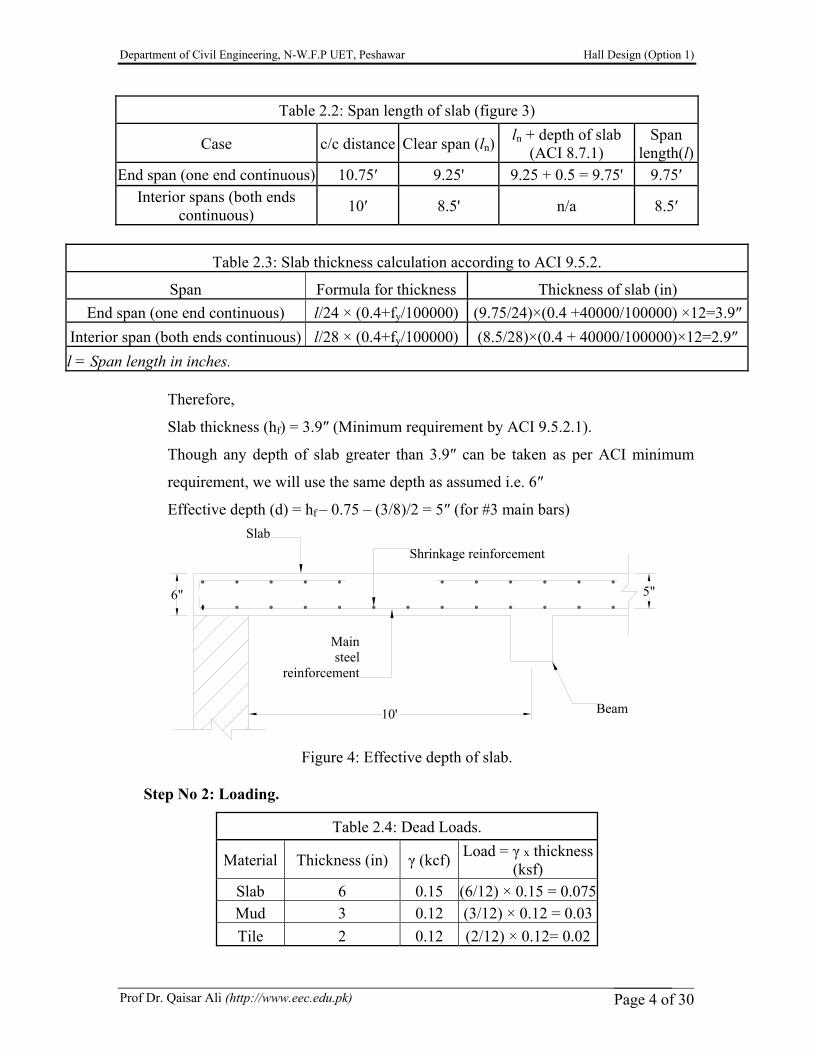
Table 2.2: Span length of slab (figure 3)
Case c/c distance Clear span (ln)ln + depth of slab
(ACI 8.7.1) Span
length(l)End span (one end continuous) 10.75′ 9.25' 9.25 + 0.5 = 9.75' 9.75′
Interior spans (both ends continuous) 10′ 8.5' n/a 8.5′
Table 2.3: Slab thickness calculation according to ACI 9.5.2.
Span Formula for thickness Thickness of slab (in) End span (one end continuous) l/24 × (0.4+fy/100000) (9.75/24)×(0.4 +40000/100000) ×12=3.9″
Interior span (both ends continuous) l/28 × (0.4+fy/100000) (8.5/28)×(0.4 + 40000/100000)×12=2.9″ l = Span length in inches.
Therefore,
Slab thickness (hf) = 3.9″ (Minimum requirement by ACI 9.5.2.1).
Though any depth of slab greater than 3.9″ can be taken as per ACI minimum
requirement, we will use the same depth as assumed i.e. 6″
Effective depth (d) = hf – 0.75 – (3/8)/2 = 5″ (for #3 main bars)
Figure 4: Effective depth of slab.
Step No 2: Loading.
Table 2.4: Dead Loads.
Material Thickness (in) γ (kcf) Load = γ x thickness (ksf)
Slab 6 0.15 (6/12) × 0.15 = 0.075 Mud 3 0.12 (3/12) × 0.12 = 0.03 Tile 2 0.12 (2/12) × 0.12= 0.02
Department of Civil Engineering, N-W.F.P UET, Peshawar Hall Design (Option 1)
Prof Dr. Qaisar Ali (http://www.eec.edu.pk) Page 5 of 30
01/11
1/12 1/121/16
1/12
19.92 in-k/ft
18.36 in-k/ft 15.48 in-k/ft
11.64 in-k/ft
15.48 in-k/ft
l = 9.25' l = 8.5'n n
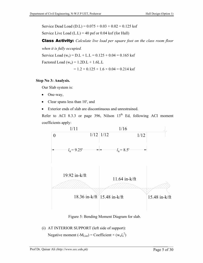
Service Dead Load (D.L) = 0.075 + 0.03 + 0.02 = 0.125 ksf
Service Live Load (L.L) = 40 psf or 0.04 ksf (for Hall)
Class Activity: Calculate live load per square foot on the class room floor
when it is fully occupied.
Service Load (ws) = D.L + L.L = 0.125 + 0.04 = 0.165 ksf
Factored Load (wu) = 1.2D.L + 1.6L.L
= 1.2 × 0.125 + 1.6 × 0.04 = 0.214 ksf
Step No 3: Analysis.
Our Slab system is:
• One-way,
• Clear spans less than 10′, and
• Exterior ends of slab are discontinuous and unrestrained.
Refer to ACI 8.3.3 or page 396, Nilson 13th Ed, following ACI moment
coefficients apply:
Figure 5: Bending Moment Diagram for slab.
(i) AT INTERIOR SUPPORT (left side of support):
Negative moment (-MLint) = Coefficient × (wuln2)
Department of Civil Engineering, N-W.F.P UET, Peshawar Hall Design (Option 1)
Prof Dr. Qaisar Ali (http://www.eec.edu.pk) Page 6 of 30
10' Beam
Mainsteel
reinforcement
Shrinkage reinforcementSlab
6" 5"
= (1/12) × {0.214 × (9.25)2}
=1.53 ft-k/ft = 18.36 in-k/ft
(ii) AT INTERIOR SUPPORT (right side of support):
Negative moment (-MRint) = Coefficient × (wuln2)
= (1/12) × {0.214 × (8.5)2}
= 1.29 ft-k/ft = 15.48 in-k/ft
(iii)AT EXTERIOR MID SPAN:
Positive moment (+MMext) =Coefficient × (wuln2)
= (1/11) × {0.214 × (9.25)2}
= 1.66 ft-k/ft = 19.92 in-k/ft
(iv) AT INTERIOR MID SPAN:
Positive moment (+MMint) =Coefficient × (wuln2)
= (1/16) × {0.214 × (8.5)2}
= 0.97 ft-k/ft = 11.64 in-k/ft
Discussion: ACI analysis vs actual conditions for beam support, concepts of hinge,
roller supports etc.
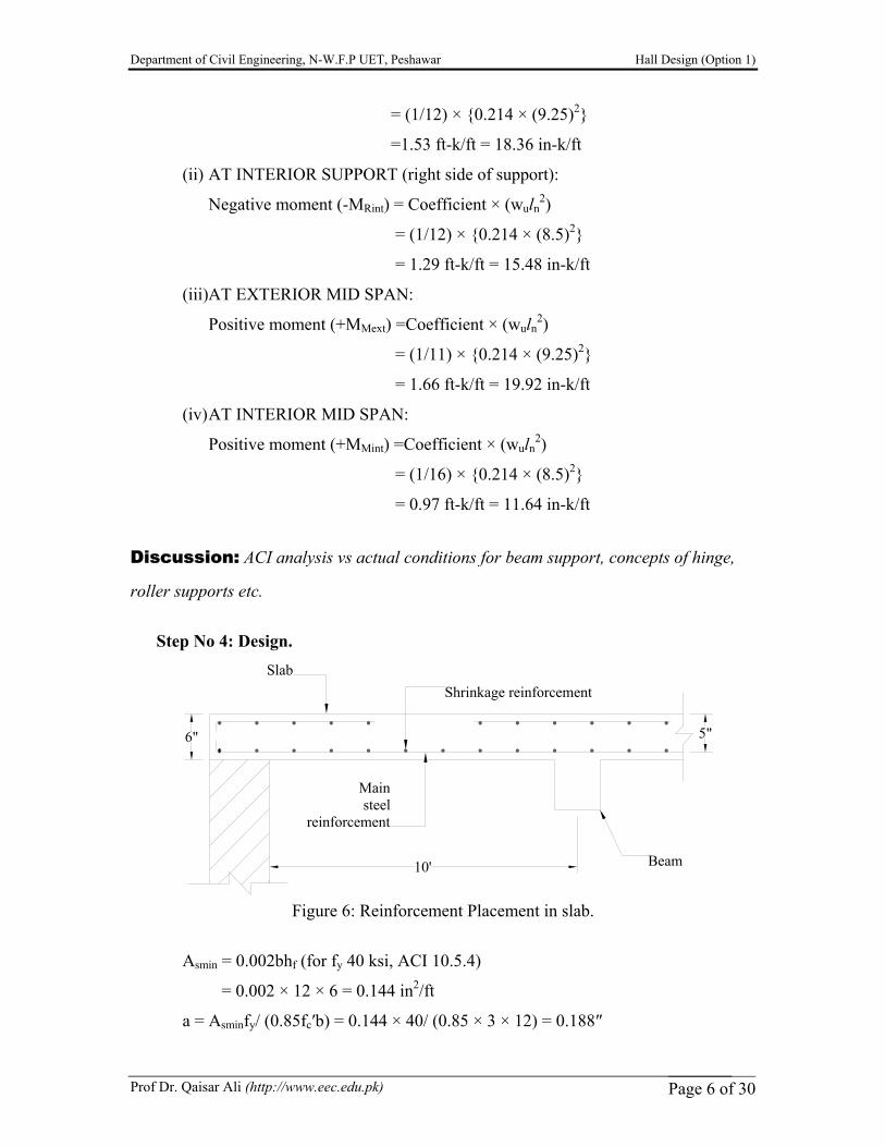
Step No 4: Design.
Figure 6: Reinforcement Placement in slab.
Asmin = 0.002bhf (for fy 40 ksi, ACI 10.5.4)
= 0.002 × 12 × 6 = 0.144 in2/ft
a = Asminfy/ (0.85fc′b) = 0.144 × 40/ (0.85 × 3 × 12) = 0.188″
Department of Civil Engineering, N-W.F.P UET, Peshawar Hall Design (Option 1)
Prof Dr. Qaisar Ali (http://www.eec.edu.pk) Page 7 of 30
ΦMn = ΦAsminfy (d-a/2)
= 0.9 × 0.144 × 40 × (5-0.188/2) = 25.4 in-k/ft
Φ Mn calculated from Asmin is greater than all moments as calculated in Step No 3.
Therefore As = Asmin = 0.144 in2/ft
Using ½″ Φ (#4) {#13, 13 mm}, with bar area Ab = 0.20 in2
Spacing =Area of one bar (Ab)/As
= (0.20 in2/0.144 in2/ft) × 12 = 16.67 in
Discussion: Bar numbers commonly used in slabs…?
Using 3/8″ Φ (#3) {#10, 10 mm}, with bar area Ab = 0.11 in2
Spacing = Area of one bar (Ab)/As
= (0.11 in2/0.144 in2/ft) × 12 = 9.16″ ≈ 9″
Finally use #3 @ 9″ c/c (#10 @ 225 mm c/c). This will work for both Positive and
Negative steel as Asmin governs.
Shrinkage steel or temperature steel (Ast):
Ast = 0.002bhf
Ast = 0.002 × 12 × 6 =0.144 in2/ft
Shrinkage reinforcement is same as main reinforcement, because:
Ast = Asmin = 0.144 in2
• Maximum spacing for main steel reinforcement in one way slab according to
ACI 7.6.5 is minimum of:
(i) 3hf = 3 × 6 =18″
(ii) 18″
Therefore 9″ spacing is O.K.
• Maximum spacing for temperature steel reinforcement in one way slab
according to ACI 7.12.2.2 is minimum of:
(i) 5hf =5 × 6 =30″
(ii) 18″
Therefore 9″ spacing is O.K.
Department of Civil Engineering, N-W.F.P UET, Peshawar Hall Design (Option 1)
Prof Dr. Qaisar Ali (http://www.eec.edu.pk) Page 8 of 30
l = 60'-0"n
b
h
h
h
w
w
f
(2) BEAM DESIGN (single span, simply supported): Data Given:
Exterior supports of beam = 18″ brick masonry wall.
fc′= 3 ksi; fy = 40 ksi
Beams c/c spacing =10′
Step No 1: Sizes.
According to ACI 9.5.2.1, table 9.5 (a):
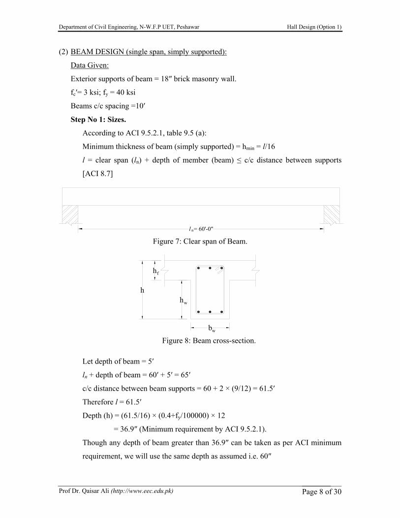
Minimum thickness of beam (simply supported) = hmin = l/16
l = clear span (ln) + depth of member (beam) ≤ c/c distance between supports
[ACI 8.7]
Figure 7: Clear span of Beam.
Figure 8: Beam cross-section.
Let depth of beam = 5′
ln + depth of beam = 60′ + 5′ = 65′
c/c distance between beam supports = 60 + 2 × (9/12) = 61.5′
Therefore l = 61.5′
Depth (h) = (61.5/16) × (0.4+fy/100000) × 12
= 36.9″ (Minimum requirement by ACI 9.5.2.1).
Though any depth of beam greater than 36.9″ can be taken as per ACI minimum
requirement, we will use the same depth as assumed i.e. 60″
Department of Civil Engineering, N-W.F.P UET, Peshawar Hall Design (Option 1)
Prof Dr. Qaisar Ali (http://www.eec.edu.pk) Page 9 of 30
103.16 k
V =84.71 k
3.355 k/ft
61.5'
wl /8 =19034 in-k2
u
Take h = 5′ = 60″
d = h – 3 = 57″
Step No 2: Loads.
Service Dead Load (D.L) = 0.075 + 0.03 + 0.02 = 0.125 ksf (Table 2.3)
Service Live Load (L.L) = 40 psf or 0.04 ksf (for Hall)
Beam is supporting 10′ slab. Therefore load per running foot will be as follows:
Service Dead Load from slab= 0.125 × 10 = 1.25 k/ft
Service Dead Load from beam’s self weight = hwbwγc
= (54 × 18/144) × 0.15 =1.0125 k/ft
Total Service Dead Load = 1.25 + 1.0125 =2.2625 k/ft
Service Live Load = 0.04 × 10 = 0.4 k/ft
ws = D.L +L.L = 1.0125 + 0.4 = 1.4125 k/ft
wu =1.2D.L + 1.6L.L =1.2 × 2.2625 + 1.6 × 0.4 =3.355 k/ft
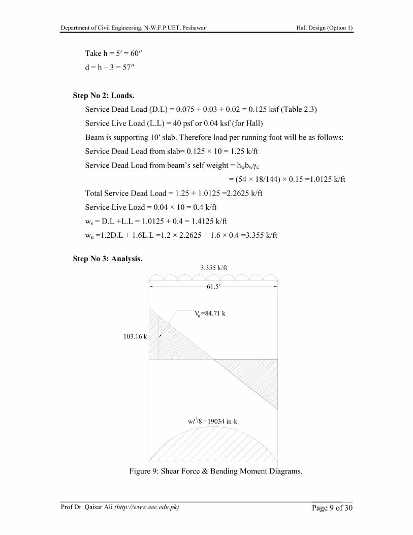
Step No 3: Analysis.
Figure 9: Shear Force & Bending Moment Diagrams.
Department of Civil Engineering, N-W.F.P UET, Peshawar Hall Design (Option 1)
Prof Dr. Qaisar Ali (http://www.eec.edu.pk) Page 10 of 30
Mu = wul2/8 (l = span length of beam)
Mu = 3.355 × 61.52/8 = 1586.18 ft-k =1586.18 × 12 = 19034 in-k
d = 57″ = 4.75′
Vmax = 103.16 k
Vu = 84.70 k
Step No 4: Design of beam.
(A) Flexural Design:
Step (a): According to ACI 8.10, beff for T-beam is minimum of:
(i) 16hf + bw = 16 × 6 + 18 =114″
(ii) (c/c span of beam)/4 =(61.5′/4) × 12 =184.5″
(iii)c/c spacing between beams =10′ × 12 =120″
So beff = 114″
Step (b): Check if beam is to be designed as rectangular beam or T-beam.
Trial #1:
(i) Assume a = hf = 6″
As =Mu/ {Φfy (d–a/2)}
As =19034/ {0.9 × 40 × (57–6/2)} = 9.79 in2
(ii) Re-calculate “a”:
a =Asfy/ (0.85fc′beff)
a =9.79 × 40/ (0.85 × 3 × 114) = 1.34″ < hf
Therefore design beam as rectangular beam.
Trial #2:
As =19034/ {0.9 × 40 × (57–1.34/2)} = 9.38 in2
a = 9.38 × 40/ (0.85 × 3 × 114) = 1.29″
This value is close enough to the previously calculated value of “a”,
therefore, As = 9.38 in2, O.K.
Step (c): Check for maximum and minimum reinforcement.
Asmax = ρmaxbwd
ρmax = 0.85β1(fc′/fy) {εu/(εu + εy)}
ρmax = 0.85 × 0.85 × (3/40) × {0.003/(0.003 + 0.005)} = 0.0203
Department of Civil Engineering, N-W.F.P UET, Peshawar Hall Design (Option 1)
Prof Dr. Qaisar Ali (http://www.eec.edu.pk) Page 11 of 30
h = 60"
b = 18"
6"
d'
d
1.5" clear cover
Asmax = 0.0203 × 18 × 57 = 20.83 in2
Asmin = ρminbwd = (200/40000) × 18 × 57 = 5.13 in2
Asmin<As<Asmax, O.K.
Note that ρmin & ρmax can also be found using table A.4, Nelson 13th Ed.
Beam (main reinforcement):
As = 9.38 in2
Using #8, 1″ Φ {#25, 25 mm}, with bar area Ab = 0.79 in2
No. of bars = As/Ab = 9.38/0.79 = 11.87 ≈ 12 bars
Use 12 #8 bars (12 #25 bars, 25 mm).
Check the capacity of designed beam:
Area of 12 #8 Bars = 12 × 0.79 = 9.48 in2
a = Asfy/ (0.85fc′beff) = 9.48 × 40/ (0.85 × 3 × 114) = 1.30″
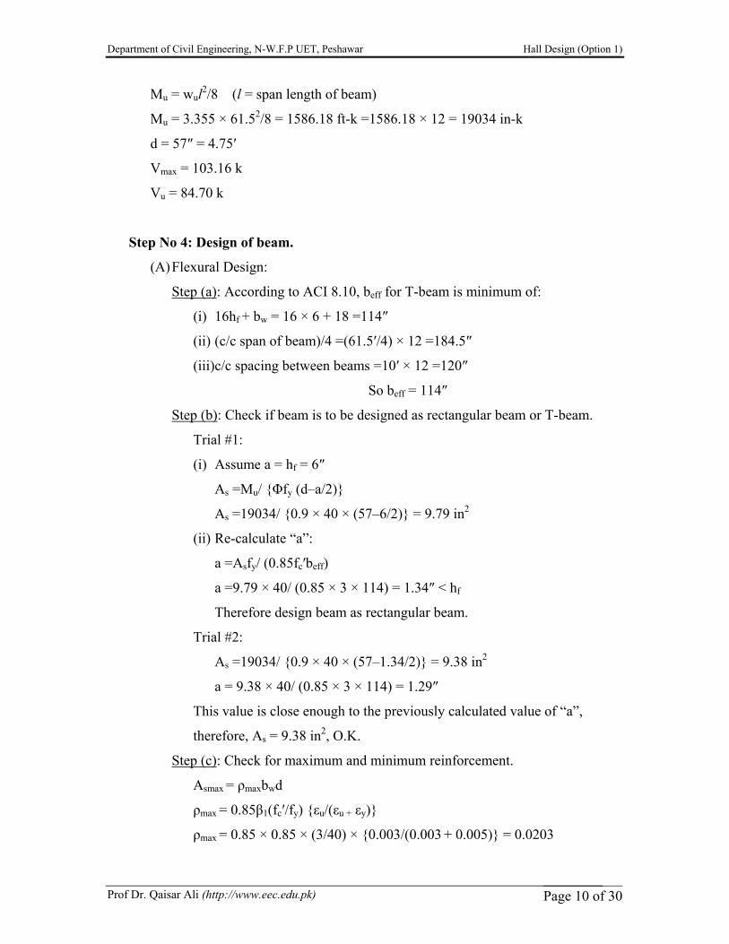
d′ = 1.5 + (3/8) + 1 + (1/2) = 3.375″
d = h – d′ = 60 – 3.375 = 56.625″
Figure 10: Beam section dimensions.
Md = ΦAsfy (d – a/2) = 0.9 × 9.48 × 40 × (56.625 – 1.30/2) = 19103.2 in-k
Md > (Mu = 19034 in-k), O.K.
Skin Reinforcement:
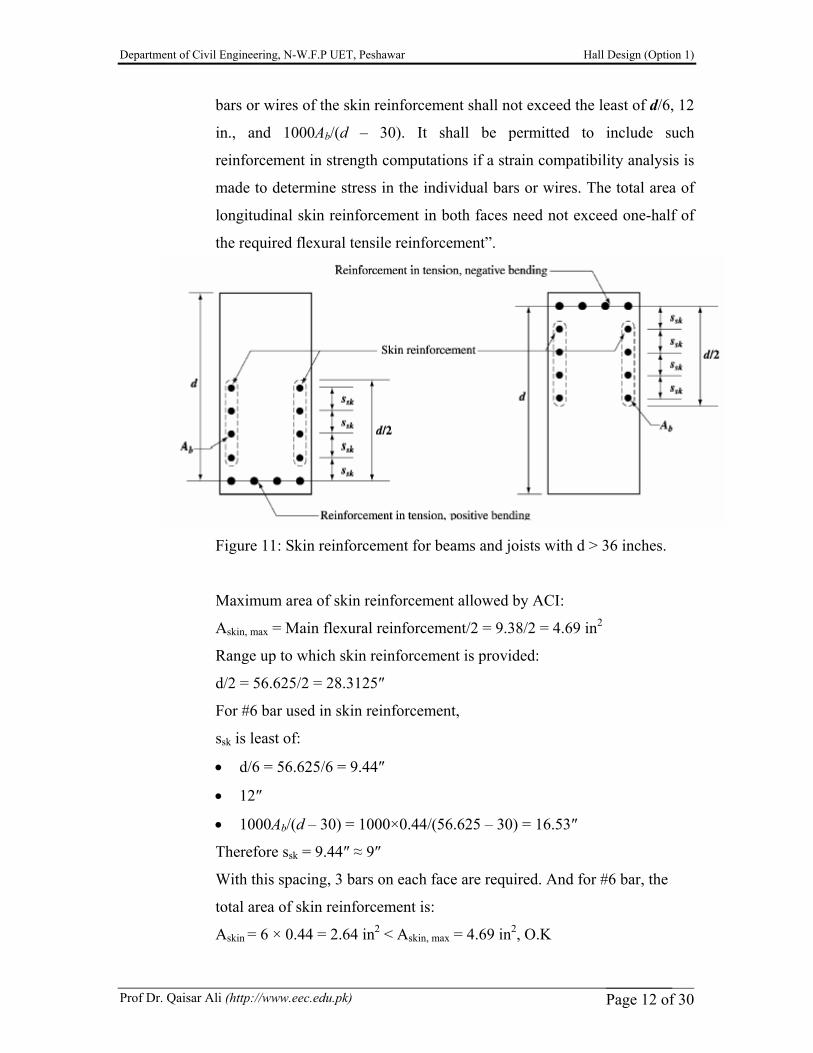
According to ACI 10.6.7 “If the effective depth d of a beam or joist
exceeds 36 in., longitudinal skin reinforcement shall be uniformly
distributed along both side faces of the member for a distance d /2 nearest
the flexural tension reinforcement. The spacing ssk between longitudinal
Department of Civil Engineering, N-W.F.P UET, Peshawar Hall Design (Option 1)
Prof Dr. Qaisar Ali (http://www.eec.edu.pk) Page 12 of 30
bars or wires of the skin reinforcement shall not exceed the least of d/6, 12
in., and 1000Ab/(d – 30). It shall be permitted to include such
reinforcement in strength computations if a strain compatibility analysis is
made to determine stress in the individual bars or wires. The total area of
longitudinal skin reinforcement in both faces need not exceed one-half of
the required flexural tensile reinforcement”.
Figure 11: Skin reinforcement for beams and joists with d > 36 inches.
Maximum area of skin reinforcement allowed by ACI:
Askin, max = Main flexural reinforcement/2 = 9.38/2 = 4.69 in2
Range up to which skin reinforcement is provided:
d/2 = 56.625/2 = 28.3125″
For #6 bar used in skin reinforcement,
ssk is least of:
• d/6 = 56.625/6 = 9.44″
• 12″
• 1000Ab/(d – 30) = 1000×0.44/(56.625 – 30) = 16.53″
Therefore ssk = 9.44″ ≈ 9″
With this spacing, 3 bars on each face are required. And for #6 bar, the
total area of skin reinforcement is:
Askin = 6 × 0.44 = 2.64 in2 < Askin, max = 4.69 in2, O.K
Department of Civil Engineering, N-W.F.P UET, Peshawar Hall Design (Option 1)
Prof Dr. Qaisar Ali (http://www.eec.edu.pk) Page 13 of 30
(B) Shear Design:
Vu = 84.71 k
ΦVc = Φ2√ (fc′)bwd = (0.75 × 2 × √ (3000) × 18 × 57)/1000 = 84.29 k
ΦVc < Vu {Shear reinforcement is required}
sd = ΦAvfyd/(Vu – ΦVc)
Using #3, 2 legged stirrups with Av = 0.11 × 2 =0.22 in2}
sd = 0.75 × 0.22 × 40 × 57/(84.71 – 84.29) = 895″
Maximum spacing and minimum reinforcement requirement as permitted by
ACI 11.5.4 and 11.5.5.3 shall be minimum of:
(i) Avfy/(50bw) =0.22 × 40000/(50 × 18) ≈ 9.5″
(ii) d/2 =57/2 =28.5″
(iii) 24″
(iv) Avfy/ 0.75√(fc′)bw = 0.22 × 40000/ {(0.75 × √(3000) × 18} = 11.90″
Other checks:
(a) Check for depth of beam:
ΦVs ≤ Φ8√ (fc′)bwd (ACI 11.5.6.9)
Φ8√ (fc′)bwd = 0.75 × 8 × √ (3000) × 18 × 57/1000 = 337.18 k
ΦVs = (ΦAvfyd)/sd
= (0.75 × 0.22 × 40 × 57)/9.5 = 39.6 k < 337.18 k, O.K.
So depth is O.K. If not, increase depth of beam.
(b) Check if “ΦVs ≤ Φ4√ (fc′)bwd” {ACI 11.5.4.3}:
If “ΦVs ≤ Φ4√ (fc′)bwd”, the maximum spacing (smax) is O.K.
Otherwise reduce spacing by one half.
Φ4√ (fc´)bwd = 0.75 × 4 × √ (3000) × 18 × 57/1000= 168.58 k
ΦVs = (ΦAvfyd)/sd
= (0.75 × 0.22 × 40 × 57)/9.5 = 39.6 k < 168.58 k, O.K.
Arrangement of stirrups in the beam: With #3, 2 legged vertical
stirrups @ 9.5″ c/c (maximum spacing and minimum reinforcement
requirement as permitted by ACI), the shear capacity (ΦVn ) of the
beam will be equal to:
ΦVn = ΦVc + ΦVs
Department of Civil Engineering, N-W.F.P UET, Peshawar Hall Design (Option 1)
Prof Dr. Qaisar Ali (http://www.eec.edu.pk) Page 14 of 30
s/2 = 4.75"
42.145 k
12.56' d = 4.75'
V = 87.22 kφV = 84.29 k
φV /2 = 42.145 k
u
#3 @ 9.5" c/c Theoretically nostirrups needed
#3, 2 legged stirrups @ 12" c/c
c
c
ΦVs = (ΦAvfyd)/smax
ΦVs = (0.75 × 0.22 × 40 × 57/9.5) = 39.6 k
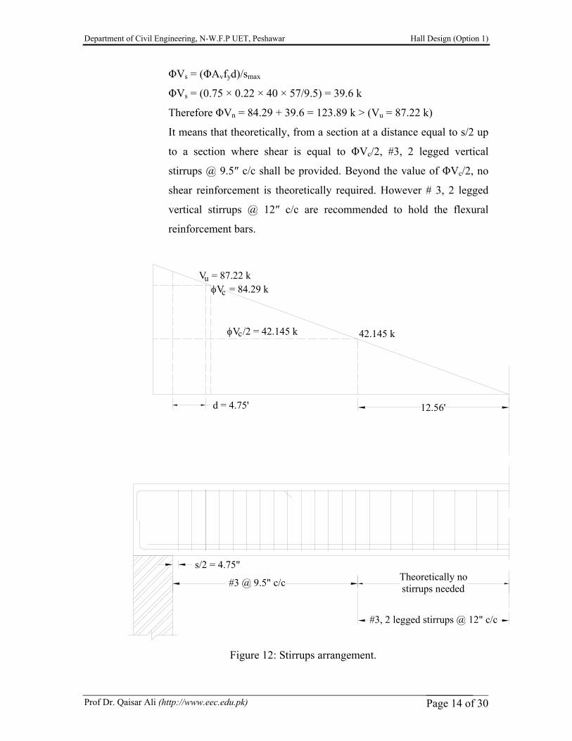
Therefore ΦVn = 84.29 + 39.6 = 123.89 k > (Vu = 87.22 k)
It means that theoretically, from a section at a distance equal to s/2 up
to a section where shear is equal to ΦVc/2, #3, 2 legged vertical
stirrups @ 9.5″ c/c shall be provided. Beyond the value of ΦVc/2, no
shear reinforcement is theoretically required. However # 3, 2 legged
vertical stirrups @ 12″ c/c are recommended to hold the flexural
reinforcement bars.
Figure 12: Stirrups arrangement.

Department of Civil Engineering, N-W.F.P UET, Peshawar Hall Design (Option 1)
Prof Dr. Qaisar Ali (http://www.eec.edu.pk) Page 15 of 30
S1 S2
A A
B1
M1 M1
M1M1
MT1 MT1
B1
B1
B1
B1
B1
B1
B1
S2 S2 S2 S2 S2 S2 S1
MT1 MT1
90'-0"
60'-0"
L /4 = 2.5' L /3 = 3.25' L /3 = 3'
L = 9.25'
11 2
MT1
1
M1 (Main steel Reinforcement)
M1 (Shrinkage Reinforcement)
h =6"f
MT1
#3 @ 18" c/c (supporting bars or chairs)
#3 @ 18" c/c (supporting bars or chairs)
L = 8.5'2
L /3 = 3' L /3 = 3'2 2
(3) DRAFTING:
(I) Slab (S1 and S2):
Panel Depth (in) Mark Bottom Reinforcement Mark Top reinforcement
S1 6" M1 3/8" φ @ 9" c/c MT1 3/8" φ @ 9" c/c Non continuous End
S2 6" M1 3/8" φ @ 9" c/c MT1 3/8" φ @ 9" c/c Continuous End
Section A-A. Refer to figure 5.15, chapter 5, Nelson 13th Ed for bar cutoff.
Department of Civil Engineering, N-W.F.P UET Peshawar Hall Design (Option 1)
Prof Dr. Qaisar Ali (http://www.eec.edu.pk) Page 15 of 30
A
A
B
B
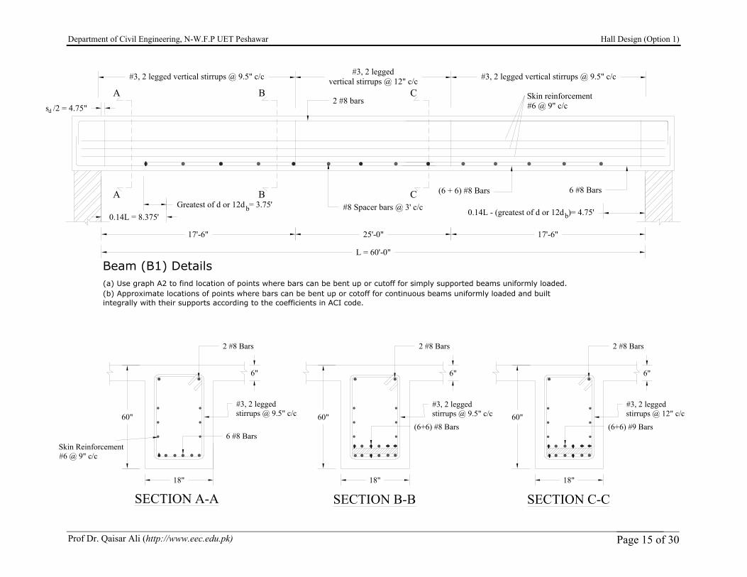
L = 60'-0"
0.14L = 8.375'
s /2 = 4.75"
0.14L - (greatest of d or 12d )= 4.75'
#3, 2 legged vertical stirrups @ 9.5" c/c
#8 Spacer bars @ 3' c/c
d
2 #8 bars
6 #8 Bars(6 + 6) #8 Bars
#3, 2 legged vertical stirrups @ 9.5" c/c#3, 2 leggedvertical stirrups @ 12" c/c
17'-6" 25'-0" 17'-6"
Greatest of d or 12d = 3.75'bb
Beam (B1) Details(a) Use graph A2 to find location of points where bars can be bent up or cutoff for simply supported beams uniformly loaded.(b) Approximate locations of points where bars can be bent up or cotoff for continuous beams uniformly loaded and builtintegrally with their supports according to the coefficients in ACI code.
C
C
Skin reinforcement#6 @ 9" c/c
SECTION A-A SECTION B-B
60"
18"
6 #8 Bars
#3, 2 leggedstirrups @ 9.5" c/c
#3, 2 leggedstirrups @ 9.5" c/c60"
18"
2 #8 Bars2 #8 Bars
6" 6"
(6+6) #8 Bars
SECTION C-C
#3, 2 leggedstirrups @ 12" c/c60"
18"
2 #8 Bars
6"
(6+6) #9 Bars
Skin Reinforcement#6 @ 9" c/c
Department of Civil Engineering, N-W.F.P UET Peshawar Hall Design (Option 1)
Prof Dr. Qaisar Ali (http://www.eec.edu.pk) Page 16 of 30
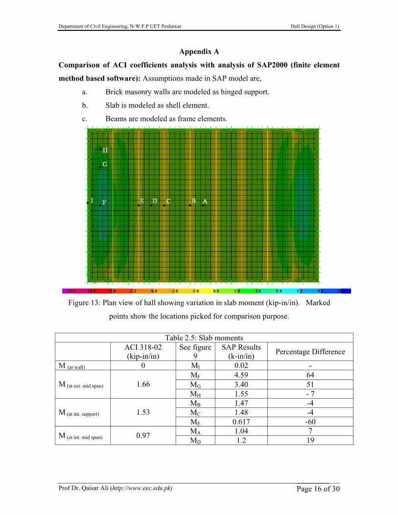
Appendix A
Comparison of ACI coefficients analysis with analysis of SAP2000 (finite element
method based software): Assumptions made in SAP model are,
a. Brick masonry walls are modeled as hinged support.
b. Slab is modeled as shell element.
c. Beams are modeled as frame elements.
Figure 13: Plan view of hall showing variation in slab moment (kip-in/in). Marked
points show the locations picked for comparison purpose.
Table 2.5: Slab moments
ACI 318-02 (kip-in/in)
See figure 9
SAP Results (k-in/in) Percentage Difference
M (at wall) 0 MI 0.02 - MF 4.59 64 MG 3.40 51 M (at ext. mid span) 1.66 MH 1.55 - 7 MB 1.47 -4 MC 1.48 -4 M (at int. support) 1.53 ME 0.617 -60 MA 1.04 7 M (at int. mid span) 0.97 MD 1.2 19
Department of Civil Engineering, N-W.F.P UET Peshawar Hall Design (Option 1)
Prof Dr. Qaisar Ali (http://www.eec.edu.pk) Page 17 of 30
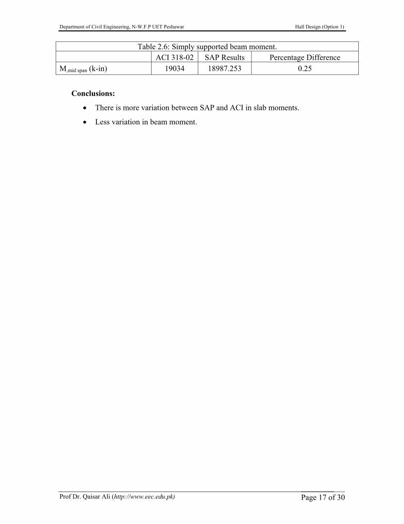
Conclusions:
• There is more variation between SAP and ACI in slab moments.
• Less variation in beam moment.
Table 2.6: Simply supported beam moment. ACI 318-02 SAP Results Percentage Difference M,mid span (k-in) 19034 18987.253 0.25
Department of Civil Engineering, N-W.F.P UET Peshawar Hall Design (Option 1)
Prof Dr. Qaisar Ali (http://www.eec.edu.pk) Page 18 of 30
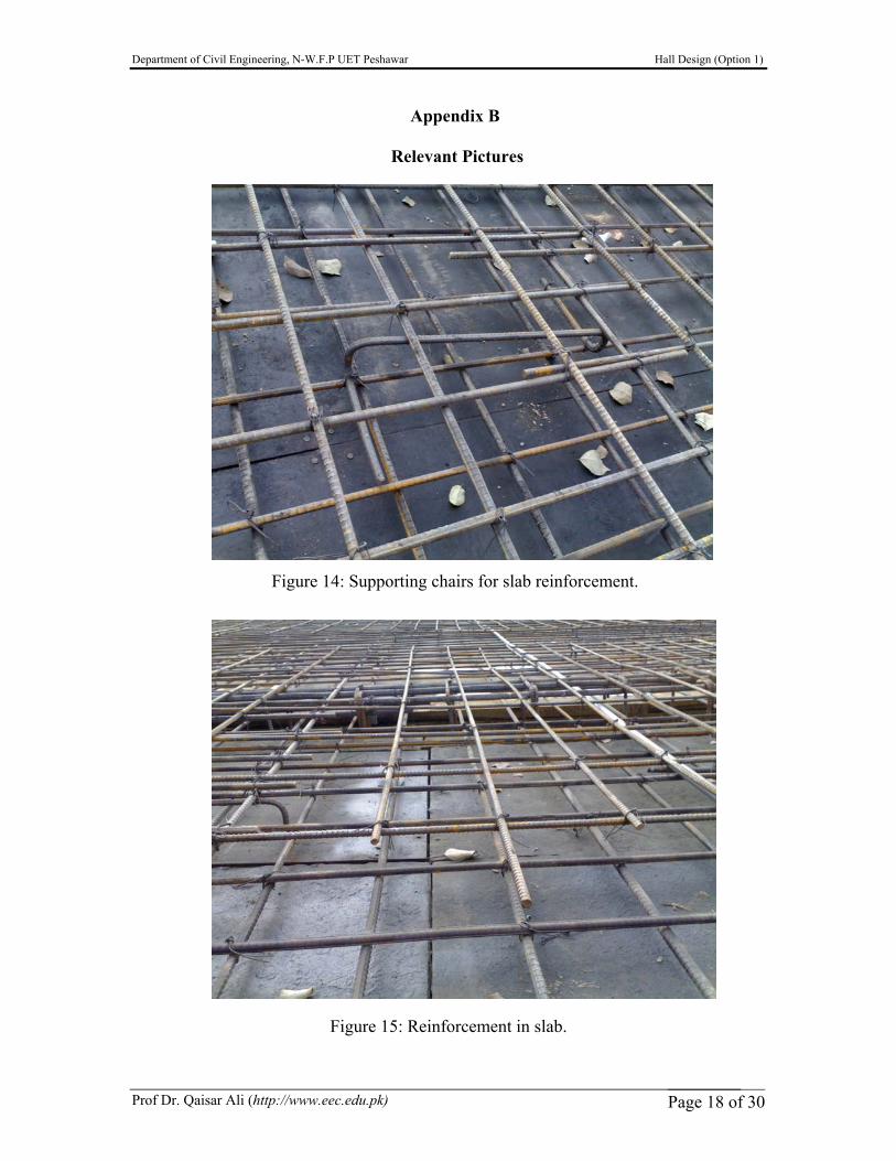
Appendix B
Relevant Pictures
Figure 14: Supporting chairs for slab reinforcement.
Figure 15: Reinforcement in slab.
Department of Civil Engineering, N-W.F.P UET Peshawar Hall Design (Option 1)
Prof Dr. Qaisar Ali (http://www.eec.edu.pk) Page 19 of 30
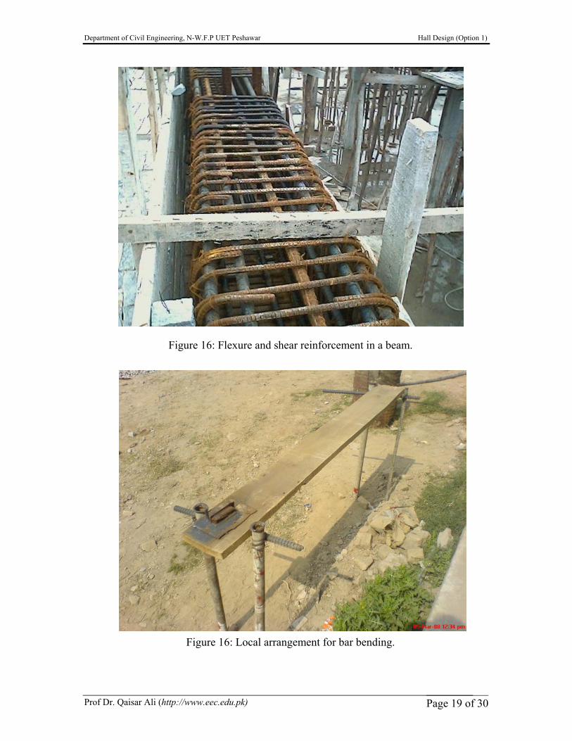
Figure 16: Flexure and shear reinforcement in a beam.
Figure 16: Local arrangement for bar bending.
Department of Civil Engineering, N-W.F.P UET Peshawar Hall Design (Option 1)
Prof Dr. Qaisar Ali (http://www.eec.edu.pk) Page 20 of 30
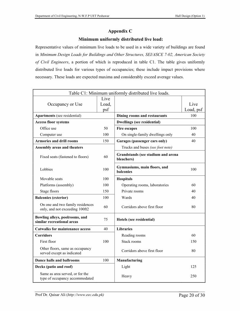
Appendix C
Minimum uniformly distributed live load:
Representative values of minimum live loads to be used in a wide variety of buildings are found
in Minimum Design Loads for Buildings and Other Structures, SEI/ASCE 7-02, American Society
of Civil Engineers, a portion of which is reproduced in table C1. The table gives uniformly
distributed live loads for various types of occupancies; these include impact provisions where
necessary. These loads are expected maxima and considerably exceed average values.
Table C1: Minimum uniformly distributed live loads.
Occupancy or Use Live Load,
psf Live
Load, psf Apartments (see residential) Dining rooms and restaurants 100 Access floor systems Dwellings (see residential) Office use 50 Fire escapes 100 Computer use 100 On single-family dwellings only 40 Armories and drill rooms 150 Garages (passenger cars only) 40 Assembly areas and theaters Trucks and buses (see foot note)
Fixed seats (fastened to floors) 60 Grandstands (see stadium and arena bleachers)
Lobbies 100 Gymnasiums, main floors, and balconies 100
Movable seats 100 Hospitals Platforms (assembly) 100 Operating rooms, laboratories 60 Stage floors 150 Private rooms 40 Balconies (exterior) 100 Wards 40
On one and two family residences only, and not exceeding 100ft2 60 Corridors above first floor 80
Bowling alleys, poolrooms, and similar recreational areas 75 Hotels (see residential)
Catwalks for maintenance access 40 Libraries Corridors Reading rooms 60 First floor 100 Stack rooms 150
Other floors, same as occupancy served except as indicated Corridors above first floor 80
Dance halls and ballrooms 100 Manufacturing Decks (patio and roof) Light 125
Same as area served, or for the type of occupancy accommodated Heavy 250
Department of Civil Engineering, N-W.F.P UET Peshawar Hall Design (Option 1)
Prof Dr. Qaisar Ali (http://www.eec.edu.pk) Page 21 of 30
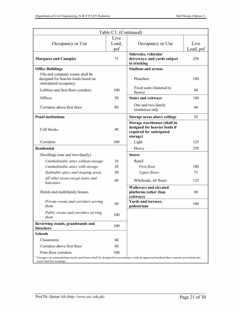
Table C1: (Continued)
Occupancy or Use Live Load,
psf Occupancy or Use Live
Load, psf
Marquees and Canopies 75 Sidewaks, vehicular driveways, and yards subject to trucking
250
Office Buildings Stadium and arenas File and computer rooms shall be designed for heavier loads based on anticipated occupancy
Pleachers 100
Lobbies and first-floor corridors 100 Fixed seats (fastened to floors) 60
Offices 50 Stairs and exitways 100
Corridors above first floor 80 One and two-family residences only 40
Penal institutions Storage areas above ceilings 20
Cell blocks 40
Storage warehouses (shall be designed for heavier loads if required for anticipated storage)
Corridors 100 Light 125 Residential Heavy 250 Dwellings (one and two-family) Stores Uninhabitable attics without storage 10 Retail Uninhabitable attics with storage 20 First floor 100 Habitable attics and sleeping areas 30 Upper floors 73 All other areas except stairs and balconies 40 Wholesale, all floors 125
Hotels and multifamily houses Walkways and elevated platforms (other than exitways)
60
Private rooms and corridors serving them 40 Yards and terraces,
pedestrians 100
Public rooms and corridors serving them 100
Reviewing stands, grandstands and bleachers 100
Schools Classrooms 40 Corridors above first floor 80 First-floor corridors 100
a Garages accommodating trucks and buses shall be designed in accordance with an approved method that contains provisions for truck and bus loadings.
Department of Civil Engineering, N-W.F.P UET Peshawar Hall Design (Option 1)
Prof Dr. Qaisar Ali (http://www.eec.edu.pk) Page 22 of 30
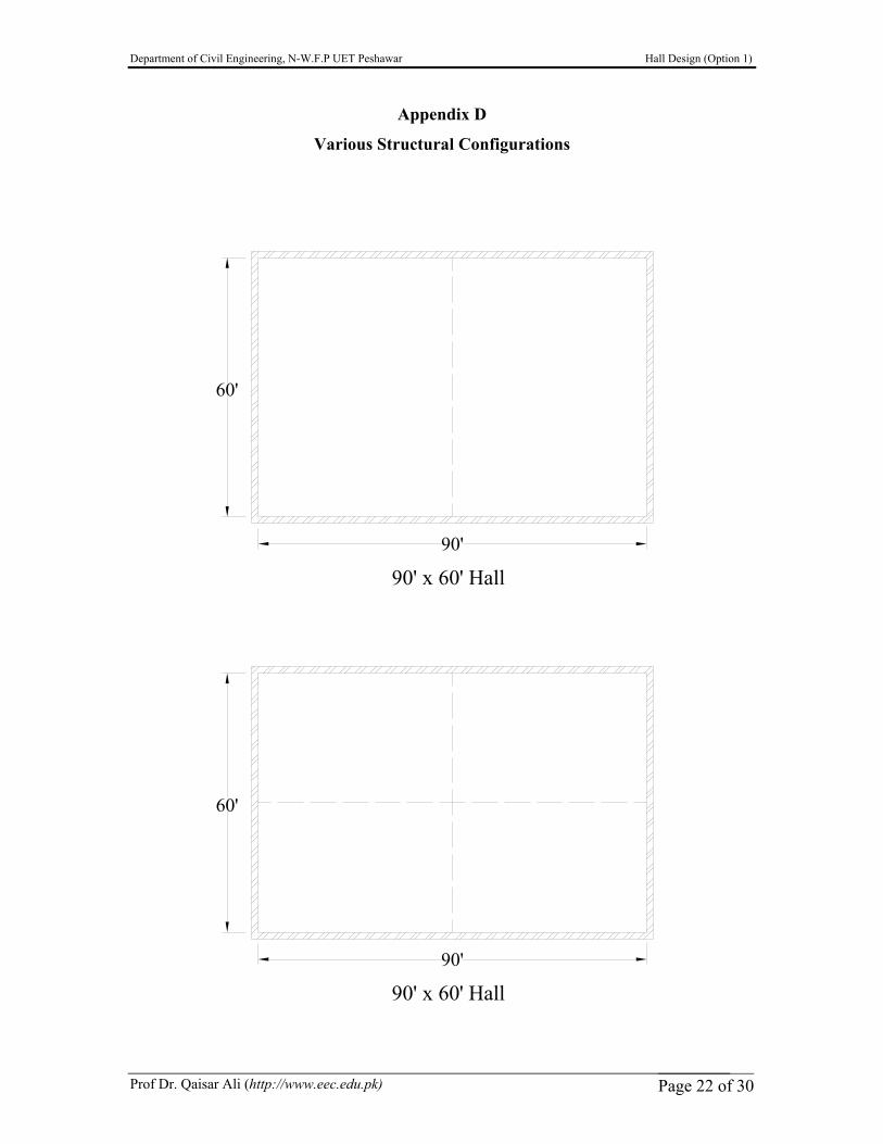
90'
60'
90' x 60' Hall
90'
60'
90' x 60' Hall
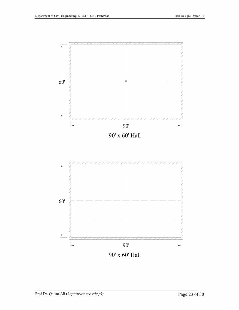
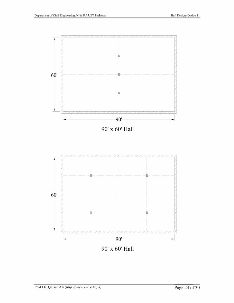
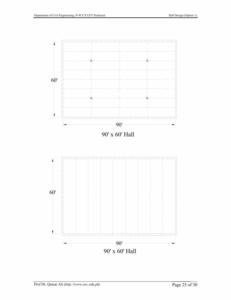
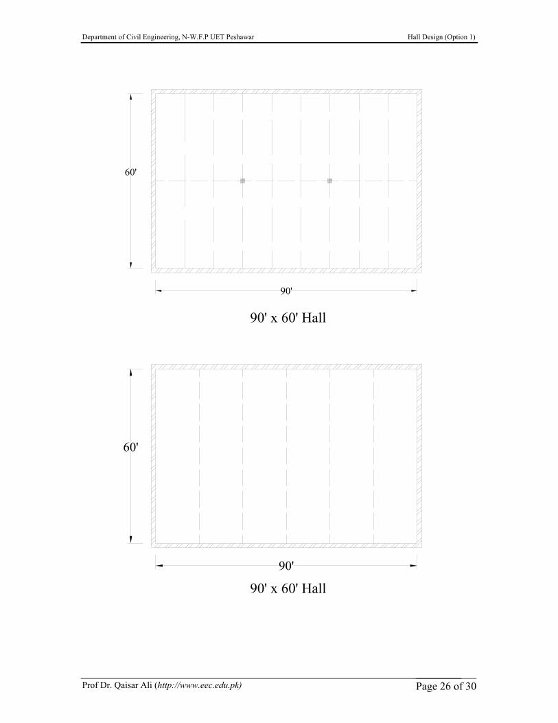
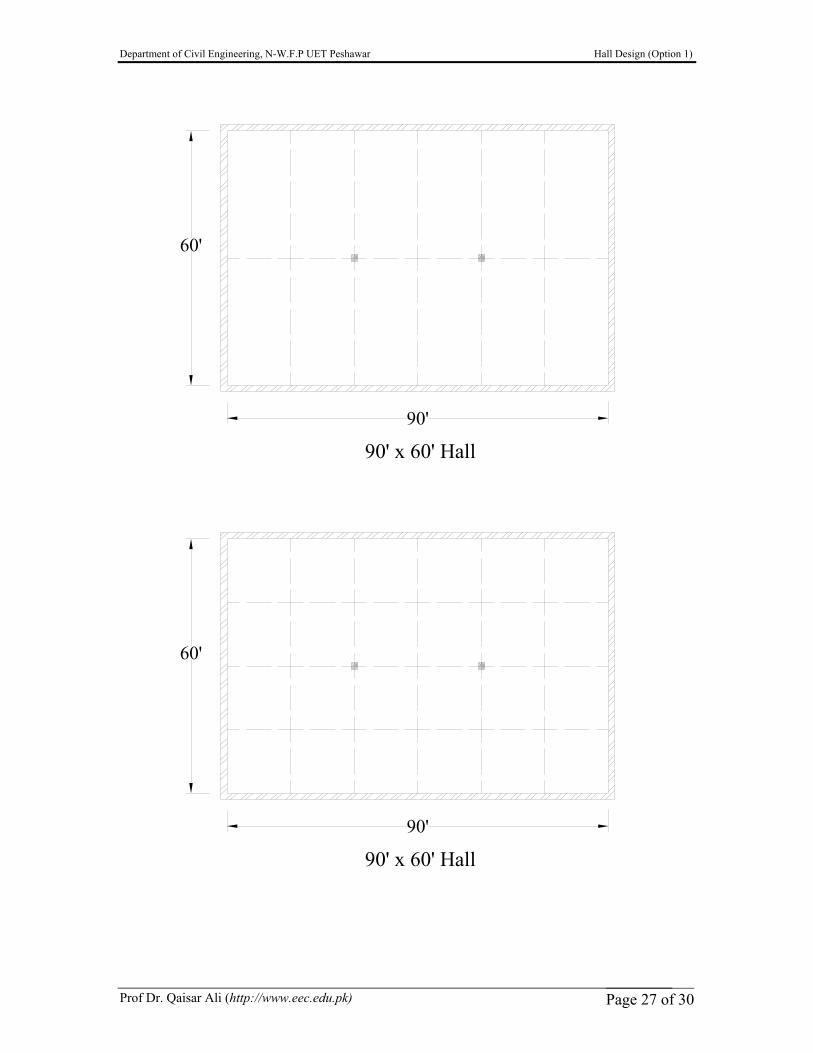
Appendix D
Various Structural Configurations
Department of Civil Engineering, N-W.F.P UET Peshawar Hall Design (Option 1)
Prof Dr. Qaisar Ali (http://www.eec.edu.pk) Page 23 of 30
90'
60'
90' x 60' Hall
90'
60'
90' x 60' Hall
Department of Civil Engineering, N-W.F.P UET Peshawar Hall Design (Option 1)
Prof Dr. Qaisar Ali (http://www.eec.edu.pk) Page 24 of 30
90'
60'
90' x 60' Hall
90'
60'
90' x 60' Hall
Department of Civil Engineering, N-W.F.P UET Peshawar Hall Design (Option 1)
Prof Dr. Qaisar Ali (http://www.eec.edu.pk) Page 25 of 30
90'
60'
90' x 60' Hall
90'
60'
90' x 60' Hall
Department of Civil Engineering, N-W.F.P UET Peshawar Hall Design (Option 1)
Prof Dr. Qaisar Ali (http://www.eec.edu.pk) Page 26 of 30
90'
60'
90'
60'
90' x 60' Hall
90' x 60' Hall
Department of Civil Engineering, N-W.F.P UET Peshawar Hall Design (Option 1)
Prof Dr. Qaisar Ali (http://www.eec.edu.pk) Page 27 of 30
90'
60'
90' x 60' Hall
90'
60'
90' x 60' Hall
Department of Civil Engineering, N-W.F.P UET Peshawar Hall Design (Option 1)
Prof Dr. Qaisar Ali (http://www.eec.edu.pk) Page 28 of 30
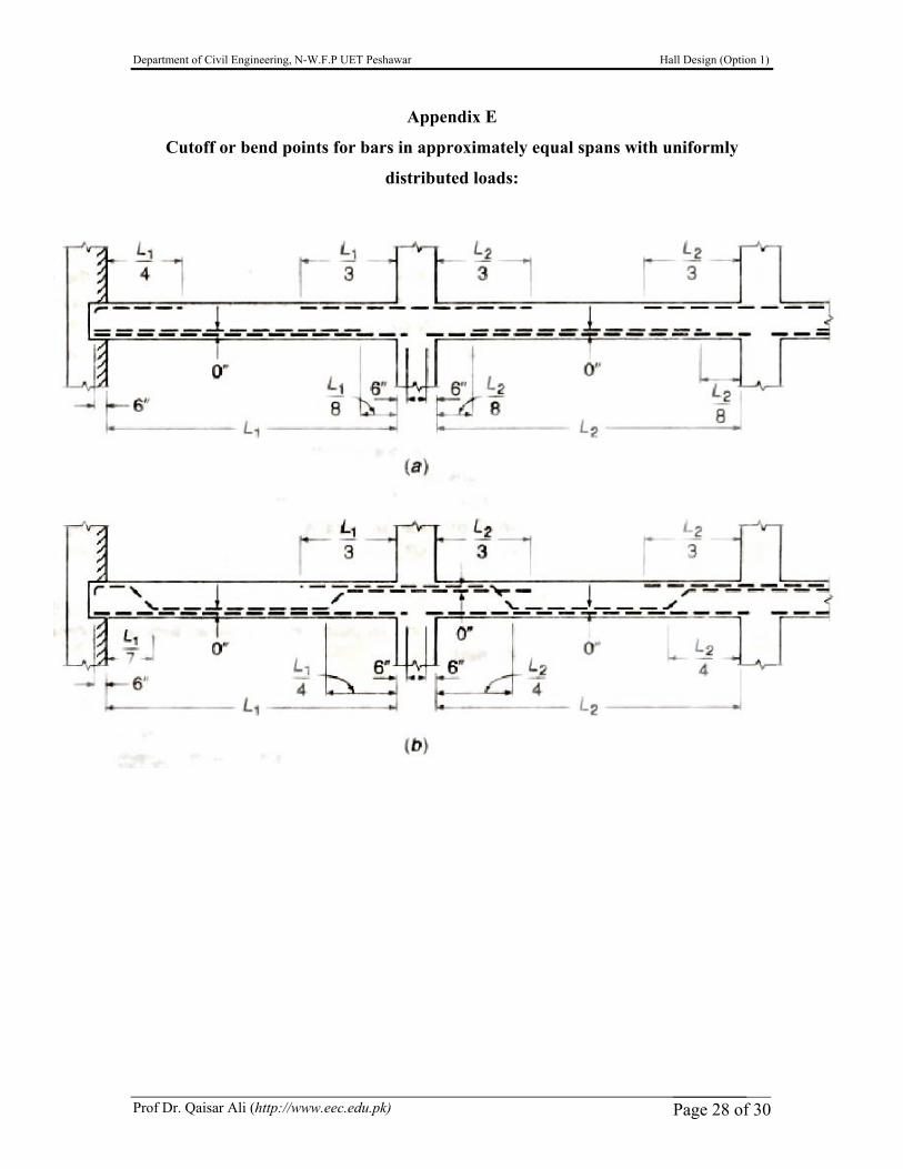
Appendix E
Cutoff or bend points for bars in approximately equal spans with uniformly
distributed loads:
Department of Civil Engineering, N-W.F.P UET Peshawar Hall Design (Option 1)
Prof Dr. Qaisar Ali (http://www.eec.edu.pk) Page 29 of 30
References
Design of Concrete Structures by Nilson, Darwin and Dolan (13th ed.)
ACI 318-02/05