Half-body and Wing Combinations in Supersonic Flow: A ...
42
R. & M. Ne. 3528 MINISTRY OF TECHNOLOGY AERONAUTICAL RESEARCH COUNCIL REPORTS AND MEMORANDA Half-body and Wing Combinations in Supersonic Flow: A Review of some Principles and Possibilities By E. L. Goldsmith and P. H. Cook LONDON' HER MAJESTY'S STATIONERY OFFICE 1968 PRICE 18s. Od. NET
Transcript of Half-body and Wing Combinations in Supersonic Flow: A ...

R. & M. Ne. 3528
MINISTRY OF TECHNOLOGY
A E R O N A U T I C A L RESEARCH COUNCIL
REPORTS AND M E M O R A N D A
Half-body and Wing Combinations in Supersonic Flow: A Review of some Principles and Possibilities
By E. L. Goldsmith and P. H. Cook
L O N D O N ' HER MAJESTY'S STATIONERY OFFICE
1968
PRICE 18s. Od. NET

Half-body and Wing Combinations in Flow: A Review of some Principles and
By E. L. G o l d s m i t h and P. H. C o o k
Supersonic Possibilities
Reports and Memoranda No. 3528*
March, 1965
Summary.
A brief review is made of simple theory for predicting the maximum lift-to-drag ratio for combinations of half-body and wing in supersonic flow, allowing for the so-called favourable interference. A comparison is given of experimental and calculated results obtained using this theory. The calculations are extended to show trends (comParing asymmetric and equivalent symmetric configurations) with design Mach number, body and wing shape, etc. The role of the engine nacelle in this context is also examined. Some sketches are included to show how interference principles might possibly be used in the design of super- sonic aircraft.
.
2.
.
Introduction
Theory
2.1.
2.2.
2.3.
LIST OF CONTENTS
General
Methods of estimating components in equation (3)
Comparison of calculated and experimental results
Calculation of (L/D)max for Specific Interference
Configurations
3.1. List of assumptions
3.2. Results
3.2.1.
3.2.2.
3.2.3.
3.2.4.
4. Conclusions
List of Symbols
References
Forebodies only - no base drag
Effect of base or afterbody drag
Engine nacelles
Volume and powerplant
Illustrations--Figs. 1 to 23
Detachable Abstract Cards
*Replaces R.A.E. Tech. Report No. 65 040---A.R.C. 27 303.

1. Introduction.
In the search for aircraft configurations to give high values of maximum lift/drag considerable interest has been shown in combinations of wing and body in which the pressure field from the body can be arranged to induce lifting pressures on the wing. One of the simplest arrangements consists of a forebody formed from half a body of revolution (e.g. a half-cone) placed underneath a wing whose leading edge coincides with the nose shock from the body. Such an arrangement has been proposed 1,2 as a basis for a possible hypersonic boost glide vehicle.
It is the purpose of this Report to review a simple theory that has been proposed 3'4 for this type of configuration and to explore some of the possibilities of applying the principles to the design of super- sonic aircraft generally.
2. Theory.
2.1. General.
The nature of favourable interference in the present context is that the volume-carrying element (the half-body) induces lifting pressure on the surface of the wing. These can be obtained by placing a forebody underneath a wing, such that the wing undersurface pressures are signficantly increased above free stream static pressure; or by placing an afterbody above a wing, such that the upper surface pressures are reduced below free stream static pressure ; or, of course, by a combination of the two. The maximum induced lift will be obtained when the wing is 'tailored' to fit the pressure field from the body. Thus in the case of a forebody underneath a wing as shown in Fig. 1, the wing leading edge should be coincident with the body nose shock and the trailing edge with the characteristic line on which free stream static pressure is obtained.
For any wing-body arrangement :
CL = CN cos a-- Cx sin a
and for small angles of incidence,
C L --" C Lo ~l- o~ d d ~ . (1)
Similarly,
C o = C:, cos a + Cn sin
-"- C x + C L a
-"- CDo+a~ff-~+a CL
-"- CDo + (G + CL) ~ (2)
where for a symmetric wing section
CLo = CLoBody + CLowB (i.e. CLowtn,, due to the influence of the body)
Coo = wave and skin-friction drag of the body and wing at ct = 0
dC L
da - lift-curve slope of the combination (for ease of calculation this is taken as for the wing alone)

dC~ i e G = ~ . . the effect of the wing pressure field on that portion of the fore or afterbody which is in-
fluenced by the wing*. For a symmetric wing body combination from linear theory this term is zero.
Thus combining (1) and (2)
Co = COo + (CLo + G) ct + ~--ff-~ a 2 (3)
From equations (1) and (3) it is found that:
dC L L ) da (4)
-~ = ± / dC L m a x 2 4Coo ~ - Czo G T CLo +- G
The upper sign refers to the half body placed underneath the wing and the lower sign to the configuration inverted.
This compares with the following equation for a symmetrical configuration :
/dC _1 2'~ CDo
which is obtained by putting CLo = G = 0 in equation (4).
(5)
2.2. Methods of Estimating Components in Equation (3).
CLo The lift induced by half of a slender body of revolution mounted on the undersurface of a flat sonic-
leading-edge wing can be obtained by integrating the axially-symmetric pressure field of a complete body of revolution over the undersurface planform of wing and body.
Thus
l~faY A"(xOdxl Cp =
o x/(x_x02_/~2y2
and
~ = f Cp dS. S
Using these equations it is shown in Ref. 3 that for any slender body of revolution under a sonic-leading- edge delta wing:
CLo 2 X Abase 2Abase = /~Sw = C~ (6)
*It is worth pointing out that in Ref. 1 the G term is omitted.
3

For other wing planforms the expressions become more cumbersome but some simplification can be effected by approximating to the planform of the wing and body by using just the wing planform.
Thus from Ref. 4 for the untapered wing and a half-cone body (Fig. 2a) using the correct planform :
11 1 [ 4fl2tan20c~
2-~z +(1- f l tan 0~) \ 12/I 4
× t,)2 ~ ( ~ x /1 - f l z tan 20c
{ 2 - s i n - t (1 -~ (1 - f l tan0~) ) - 1 _11 (1 - f l tan Oc)'] 2 12 /
1 (11~ 2 1 cosh- 1 l~ ~_ flz tan 2 0c cosh- 1 _ _
1 -~2(1 - f l tan 0~) \~2J fl tan 0 c
x/l_fltanOcX/l+fltanOc \~2/t(li)2 (1--fltanOc)2+ ~/ f~(1--fi tanOc)t 3 ~/2- /~(1-f l tanOc)}]
and using the approximate planform (Fig. 2b) where now 11 is the root chord of the wing
(7)
C L 0 i ' 11 (2/2--/0 llZ V 12
1-2 ~//~
+12 [2-\{1-11~lzJ sech-1 ( 1 - / ~ ) - s i n -1 ( 1 - / ~ ) ] t
For the fully tapered arrowhead wing using the approximate planform (Fig. 3)
(8)
4r~ / t , - 1 , /~l+l CL° = ~o2 V / t ~ tan- ~ / t ~ - - 1 (9)
where
tan o~ t l ----- t a n #
Results for CLo for delta and arrowhead wings with conical half bodies can also be obtained by numeri- cally integrating C v calculated from exact cone flow tables s over wing and body planform areas and in Fig. 4 an indication is given of the errors due to the use of slender body theory in this respect.
G
This quantity is most readily evaluated by assuming that the wing pressure field at incidence is constant over the body area and equal to the pressure at the root chord of the wing 3.

For a sonic-leading-edge wing:
G = 2rg #sw
which reduces to
G 2r~ Co
for the sonic-leading-edge delta. For a supersonic-leading-edge wing:
G = 2r~ S~
tan2
4f12tan22 -- 1
-1 1 ' c o s
where 2 is the wing apex semi-angle. For a subsonic-leading-edge wing:
(lO)
where
01)
(12)
2 tan2 Abase G - - - (13)
E(K') S w
E is a completeelliptic integral of the second kind
K ' = I~S-K~-K2, K = t i t a n 2 .
2.3. Comparison of Calculated and Experimental Results. dCL
CLo, Coo and ~ can all be calculated for simple shapes by standard methods and by those mentioned
in 2.2. above and compared directly with experimentally measured values. G can of course be derived directly from wind tunnel measurements of axial force variation with incidence. It is particularly simple however to rearrange equation (4) to obtain :
(~)max -EL° --~/ d~ kO] max (14)
or by considering the expressions for (L/D)maxand (L/D)mi. to obtain :
d~ 1 1
D max D min
+ CLo (15)

where
dC L dec
/ dC L 2 4Coo ~ - CLo G + ('1.<,- G
These methods give a mean value for G and avoid the difficulty of deciding on an appropriate mean slope for C~ vs. ~.
It is worth noting that if the wing section is not symmetrical, then :
CLo = CLo B -}- CLown "~ CLo w
so that :
dC L da
dCt C (G+CLo~)+(G+CLow)_CL ° 2 Coo dc~ Lo
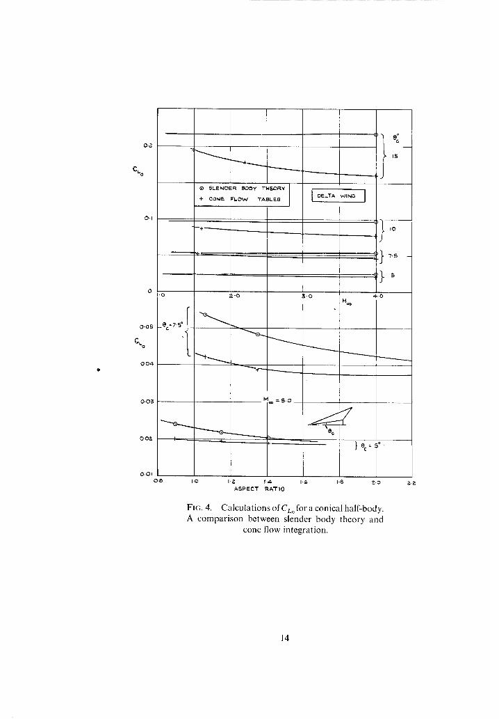
hence if equations (14) or (15) are applied for the calculation of G, we are now calculating G' = G + CL,,w. Results of this comparison for cases where the leading edge of the wing is sonic or supersonic are shown
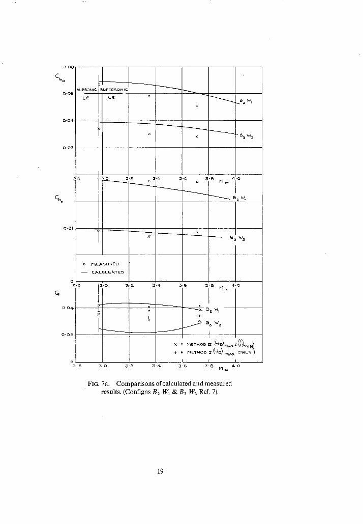
in Figs. 5 to 7 and for sonic or subsonic leading edges in Figs. 8 to 10. Both calculated and experimental results have been taken from Ref. 6 for Figs. 5 and 6.
Agreement in the case of the sonic-leading-edge appears to be fairly good but increasing departure from this condition towards either subsonic or supersonic leading edges leads to increasing errors in prediction of practically every quantity.
For the subsonic leading edges the lack of agreement is understandable. CLow~ has been calculated by a numerical summation of cone flow pressures over the appropriate planforms and the assumption of independence of lower and upper surfaces of the wing is no longer justified. Drag due to lift has been taken as C~. :~ as for the sonic and supersonic leading edge cases, i.e. leading-edge suction has been ignored.
It would appear from the comparisons that there is justification for using the simple theory when the leading edge of the wing is sonic or slightly supersonic but that away from this condition the theory is inadequate.
3. Cah'ulalion o f ( L/ D ) ...... 1or Spec!fic Interfbrence Configurations. In this Section the simple theory of Section 2 is applied to several types of interference configuration.
Each configuration is assumed to be 'on design' (i.e. to have a sonic-leading-edge wing) at any given Mach number. The object of the calculations is to see if any general trends or indications emerge as to the usefulness or otherwise of interference principles for aircraft design at supersonic speeds.
3.1. List of Assumptions. CL, , (from equation (6))
Ct.,, = (7~ for sonic-leading-edge delta and axi-symmetric half forebody
= ~ for sonic-leading-edge delta and Sears-Haack half body of fineness ratio d/1, where
1 = 2Co

CDo
CDo : CDwave "q- CDskixL friction
CDwav ° = CD0wi ~ g-~ CO0Body
CDoBo,~y = Cp .. . . . . . for a conical forebody
= 5"55 7 rc cot # for a Sears Haack half body
Coow,n ~ is obtained from Ref. 9 for a sonic-leading-edge delta with tic -- 0.02
C m = skin-friction drag coefficient - C: x S: Sw
The same variation of Reynolds Number (R.N.) with Mach number has been taken as in Ref. 10 i.e.
3 R.N. = ~ x 1 0 6 x c o
where
Sw = 6000fi 2 •
Co rather than C has been used for ease of calculation for all configurations. This probably slightly underestimates mean C: for the forebody only configurations and slightly overestimates for the forebody plus afterbody configurations. The variation of C: with Reynolds number and Mach number has been taken from Ref. 11.
G (from equations (6) and (10))
G = 2CLo for sonic-leading-edge delta wing and half forebody or Sears-Haack half body. 7~
dC L dc~
d : : for wing-body combinations has been taken to be the same as for the wing alone
i.e.
d C L 4 for a sonic leading edge delta wing (and from Ref. 12 for other conditions).
Volume parameter ~:
Body volume T - - ,~3/2
~w

= 16 (tan i,) s'e \l,el for a Sears Haack half body and a sonic-leading-edge delta wing
(,:0) 2 = 6 (tan #)s,,2 ~ for a conical half forebody and a sonic-leading-edge delta wing.
3.2. Results.
3.2.1. Forebodies only ~7o has'e draq. From equations (4) and (5) the gain in (L/D) ...... by using asymmetric rather than symmetric configurations can be calculated for configurations having the same body vohlme, wing shape and planform area. Some restllts for conical forebodies and sonic-leading-edge delta wings are shown in Fig. 11. As can be seen the gains are not large but become more significant sit the higher Mach numbers. As noted earlier C~,,, is dependent only on body base area and hence a body shape should be chosen which has the least drag for a given base areai'length 2. For the higher Math numbers this is approximately a ¼ power body i.e. a body shape defined by"
I%
It is shown in Ref. 3 that use of this shape body significantly raises the values of (L/D) .. . . but that the gains over the equivalent symmetric configuration remain very similar to those calculated for conical forebodies.
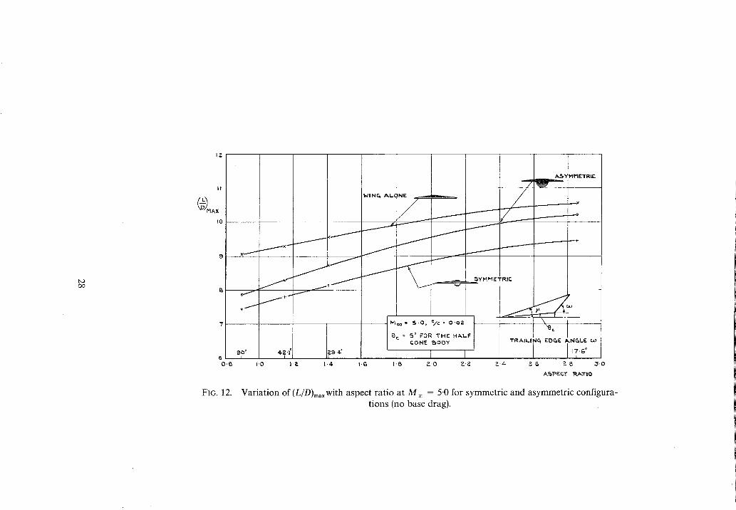
If now the trailing edge of the wing is swept back so as to cover more of the body pressure field there dC~
is a marked increase in (L/D)m~(Fig. 12) but this is mainly due to the improved d~ -~ of the basic wing
shape. In terms of improvement over the equivalent symmetric configuration, for the delta wing the in- crease in (L/D) ...... is 6 per cent and for the case where the trailing edge is swept at the Mach single corre- sponding to the cone surface Mach number the increase is 8 per cent. Thus when making comparisons sis to the effectiveness of asymmetric configurations there seems to be little point in considering any other wing shape than the delta.
Fig. 13 shows that, ignoring base drag, a half conical body of semi-angle 3 to 5 deg can be carried with a value o f ( L / D ) ...... which is little different from that for the wing alone.
This indicates the way that interference principles should be used (in their half body and wing form) in the design of supersonic aircraft. Thus if the fusclage volume specified is greater than the represenled by the approximaie cone semi-angle in the range 3 to 5 deg, then the rest of the volume should be added in a non-interference manner i.e. so as to give minimum additional drag. This is somewhat crudely illustrated in Figs. 14 and 15. Thus at M , = 2.5 (Fig. 14) for values of z below 0.028 it is preferable to put all the volume into the half cone body alone but above z = 0.{)28 it is advantageous to limit the cone single and add the remaining volume in the form of a cylindrical extension to the half cone body.
3,2.2. E[li'ct o f base or qfterhody draq. So far the considerations have been limited to arrangements having forebodies terminating in a large base area whose drag has been ignored. For possible hypersonic aircraft this is probably not unreasonable in that :
(a) Base drag is a decreasing proportion of total drag as Math number increases.
(b) Rocket exhaust nozzles could conceivably occupy the majority of the base area. If, however, the more general applications of this type of configuration are being considered the effects
of base and afterbody drag may be significant. The influence of adding air breathing engines must also be considered.
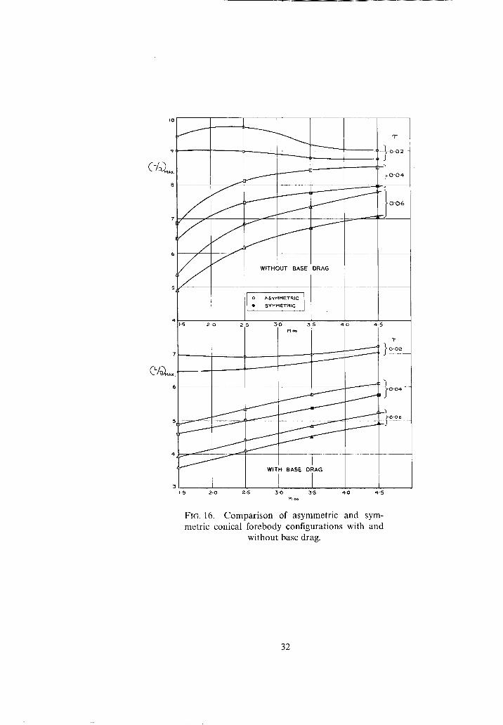
The simple effect of inclusion of base drag (derived from Ref. 13) in the calculation of (L/D) ..... for asymmetric and symmetric conical forebodies is shown in Fig. 16. As can be seen the effect of base drag is to roughly halve the gain in (L/D) .... arising from the use of favourable interference.

The influence of afterbody drag can be seen by calculating (g/D)max for asymmetric and symmetric configurations using a Sears-Haack shape for the body. For the asymmetric configuration the forebody will theoretically have twice the wave drag of the symmetric forebody of the same volume. The afterbody however is not underneath a wing surface and hence its wave drag will lie between once and twice the wave drag of the symmetric afterbody of the same volume. Thus if the wave drag of the symmetric body is CDoB that of the asymmetric body will lie between 1.5 and 2 CDoB. From Fig. 17 it can be seen that even if the most optimistic assumption is considered the gains in (L/D)m~xare very small.
If the original symmetric body is split down a horizontal centreline and the two halves displaced longitudinally so that the afterbody of the top half is above the wing and the forebody of the bottom half is below the wing as in Fig. 18 the interference effects are being used twice. The wave drag of the body can now be said to lie between that of the original symmetric body of length I and a new symmetric body
of length 2 " Comparing the asymmetric configuration with a symmetric configuration having either of
these two lengths (Fig. 18) shows that (with the most favourable assumption for the wave drag of the asymmetric configuration) a substantial gain in (L/D)m,x particularly at the lower Mach numbers is possible.
At the higher values of r when the wave drag of the body is a fair portion of the total CDo it is obvious that a more accurate idea of CDo~ must be obtained before the results can acquire any quantitative significance.
It is interesting to note however that the variation with Mach number is opposite in form to that calculated for slender wings in Ref. 10 as shown in Fig. 19.
3.2.3. En.qine nacelles. Just as the pressure field from the volume-carrying element is used to affect lifting surface pressures, so that of the basic engine nacelle configuration can be used in a similar fashion. For an isolated nacelle the wave drag will depend on the ratios of entry and exit area to nacelle maximum cross sectional area, A~n/Ama×and Aex/A . . . . to the fore and aft cowl shapes and their fineness ratios and to the wetted surface area. An overall fineness ratio for the nacelle has been assumed (this is often dictated in practice by internal flow considerations, length/diameter ratio of the engine etc) and conical external surfaces for the fore and afterbody shapes. A typical variation of Aen/Am,xand A~,JAm~ x with Mach number is shown for a turbojet having reheat at the higher Mach numbers in Fig. 20. This assumes that entry size is matched to the engine airflow and that the exit nozzle expands the internal flow to the ambient static pressure at all Mach numbers.
If entry and exit size are approximately equal nacelle interference effects can be used only if the afterbody is placed behind the trailing edge of the wing (nacelle underneath the wing) or the forebody in front of the leading edge (naceile above the wing) as shown in Figs. 2a and b. However, as Mach number increases and the exit area starts to increase at a greater rate than the entry area the whole nacelle can be placed underneath the wing (Fig. 20c) and some benefit can be expected since there is now in effect a forebody (with base area equal to A~x-Aen) and no concomitant base drag so far as interference effects are con- cerned. Thus an increasing advantage by using the asymmetrically placed nacelle is shown (Fig. 21) as free stream Mach number increases.
3.2.4. Volume and powerplant. With the three basic components, wing, body and powerplant particularly at the higher Mach numbers there are now a number of arrangements which can theoretically enhance LID by appropriate use of favourable interference. Some possibilities are sketched in Figs. 22a and b.
It should not be forgotten that a favourable interference effect between powerplant and volume rather than between powerplant or volume and lifting surface is possible, i.e.,the excess exhaust nozzle area can be used to reduce or even eliminate the afterbody drag associated with a normal body shape.
The scheme (d) shown in Fig. 22b has been selected to illustrate the order of the gains to be expected over the equivalent symmetric configuration. As can be seen (Fig. 23) an increasing advantage is available at Mach numbers in excess of 2.5.

4. Conclusions.
(I) The simple theory of Ref. 3 is summarised and extended slightly and it is shown that the values of (L/DI .... predicted are in reasonable agreement with measured values for slender halfbodies placed beneath sonic-leading-edge delta wings.
t'2) At off-design condition, i.e. when the leading edge of the wing is either sub- or supersonic, predictions can be considerably in error.
(3) Calculations comparing asymmetric and equivalent symmetric configurations show that if base drag is neglected, a considerable amount of potential storage volume can be carried underneath a wing, with L/D values which are equal to or slightly in excess of those calculated for the wing alone.
(4) Calculations with base or afterbody drags included show that gains in L/D over equivalent sym- metric configurations are generally small and can be negative in some cases.
1'5) Gains in L/D are obtained above M = 2 by positioning an engine nacelle underneath the wing rather than symmetrically with respect to it: these gains increase fairly rapidly with increase of Mach number.
1'6) Some suggestions are sketched to show possible ways of applying interference principles in the design of supersonic aircraft.
10

A
Co
CD
CL
d
G
1
M
F b
S~,
SI
t/c
Oc
"C
CO
()o
()wB
()w ()B
()ex
()e.
()max
()~
()baso
LIST OF SYMBOLS
Cross-sectional area
Root chord of wing
D Drag coefficient -
q~oSw L
Lift coefficient - qo~S~
Max diameter of body
Rate of change of axial force with incidence - -
Length of body = 2Co
Mach number
Body base radius
Planform area
Wetted area
Thickness-chord ratio of wing
Angle of incidence
1
Mach angle
Cone angle
Shock-wave angle
Body volume Volume coefficient - (Sw) 3/2
Sweepback angle of trailing edge
At zero incidence
On wing due to influence of body
Wing
Body
At the exhaust nozzle exit
At the inlet entry plane
At the engine maximum area section
Free-stream conditions
At the base of the body
dC~ d~
11

No. Author(s) 1 A.J. Eggers and
C. A. Syverston
2 A.J. Eggers, Jr. ..
3 E. Migotsky and G. J. Adams
4 ,I. W. Reyn and J. H. Clarke
5 Z. Kopal ..
6 D.H. Dennis and R. H. Peterson
7 D.F. Hasson and J. G. Presnell
C. A. Syverston, T. J. Wong . and H. R. Gloria
9 R.A. Bishop and E. G. Cane.
10 D. Kiichemann ..
11 W.F. Cope . . . .
12 A. Stanbrook . . . .
13
LIST OF REFERENCES
Title, etc. Aircraft configurations developing high lift drag ratios at high
supersonic speeds. NACA RM A55L05, ARC 18632. 1956.
Some considerations of aircraft configurations suitable for long range hypersonic flight.
Hypersonic Flow; Proceedings of the Symposium of the Colson Research Society held in the University of Bristol 1959.
Some properties of wing and half body arrangement at supersonic speeds.
NACA RM A57E15. 1957.
An assessment of body lift contributions and of linearised theory for some particular wing-body configurations.
Polytechnic Institute of Brooklyn, Pibal Report No. 305, June 1956.
Tables of supersonic flow around cones. M.I.T. Department of Electrical Engineering Center of Analysis
Tech. Report I. 1947.
Aerodynamic performance and static ability at Mach numbers up to 5 of two airplane configurations with favourable lift inter ference.
NASA Memo 1-8-59A. 1959.
Static lift, drag and pitching moment characteristics ;~z~l-~ ~ .... and modified-diamond planforms combined with several different bodies at Mach numbers of 2-97, 3.35 and 3"71.
NASA Memo 1--24 59L. 1959.
Additional experiments with fiat-top wing-body combinations at high supersonic speeds.
NACA RMA 56 1 11.
Charts of the theoretical wave drag of wings at zero lift. A.R.C.C.P. 313. June 1956.
Some considerations of aircraft shapes and their aerodynamics for flight at supersonic speeds.
R.A.E. Tech Note Aero 2626, June 1959. A.R.C. 21 102.
The turbulent boundary layer in compressible flow. A.R.C.R. & M. 2840. November 1943.
The lift curve slope and aerodynamic centre position of wings at subsonic and supersonic speeds.
R.A.E. Tech Note Aero 2328. A.R.C. 17615.
Handbook of Supersonic Aerodynamic Data Vol. II. R.A.E. GW/Handbook/ l .
12

WING L.E.. COII'4CIDF..G / / / )
hZ;" WaNC~ "r ~ coJ~cI~ wiTH LI~ Cp o
FIG. |. Wing shown blanketing all of the favour- able pressure field from a conical body.
(b)
FIG. 2. Notatioo for swept untapered wing.
" CO ~ 1
FIG. 3. Notation for arrowhead wing.
13
0.2.
C%
0-1
0.05
C~ o
004
" 15
® ~L~.NDER BC)Oy THEORY ] I I + COP4F-. #'LOW TABL¢.S DELTA WPNG
I.O
-ec=75° I
+
-C) 3"0 H
t IO
.) 7,5
4,-0
0.0~
O'OZ I
M ~, =.,5,0
}ec°s°
O. lOI 0.~ I,O I," f ' 4 I'C~ 1.8 ~..O
ASPECT RATIO 2..2.
FIG. 4. Calculations of CL,, for a conical half-body. A comparison between slender body theory and
cone flow integration.
14

O. 05
0.0~.
C~o
0.01
~,'0
0'008
Co o
0 .007
O.OOG
0.005 a'O
$USSON IC 5UP~RSO~4IC I,.. ~. L .& .
O M E A S U R E D
CAL.CULATS D
0.03
G
O,OZ
O.OI
3 . 0
3 , 0
i
4"0
4,-0
p
M © 5"0
Ma~ ' 5 -0
FIG. 5a.
3.0 ,4,.0 Mer~
Comparison of calculated and measured results (Model 3 Ref. 6).
S.O
15

1.4
dC~. dE
1.5
I'~
I-O
0 9
0 ' 8
4- 2 0
I
0 MEASUI:~ED - - C A L ~ L J L A T E ~
I SONIO
L.F_.
Pqwaa soov
4 " 0 Moo 5'D
3"0 4"0 5 '0 M m
71" :o °
FIG. 5b. Comparison of calculated and measured results. (Model 3 Ref. 6).
16

0 . 0 3
0 .02.
CL o
0"01
O
i
SUBSONIC
L.E.
Z.o
I I SUPERSONIC
L E .
~-o 4'o M ~ 5.0
O. 007
Co o
0.o0~
0 '00! 2'O
0 " 0 2
0 ' 01
l (9 MKA,~URE.D - - CALCULATED
, . 0 4 - o M m 5 . o
i i
2"0
FIG. 6a.
,5-0 4-'0 Moo
Comparison of calculated and measured results. (Model 1 Ref. 6).
5"0
17

1.6
1.4.
f.3
I,&
I,I
1.0
0 . 9
0 .8
?
FIG. 6b.
4"
3
Comparison of calculated and measured results. (Model 1 Ref. 6).
18
0-0~"
CL o
O-OE
O. 04
0.02
%
0.01
C, Z 8
O-O&
o
3 -0
i
1
~-~ 3-4-
---7-
+ x
3"0 3"P- 3 "4-
M =
~ ~ ~ - - ~ B ~ W I +
p , '~t 3
% ~ METHOI) II" (~/D)MP',~-~ MI
* • METHOD • ~,L/O) MA.% ONLY )
I [ I
M ~
FIG. 7a. Comparisonsofcalculated and measured results. (Configns B 2 W 1 & B 3 W a Ref. 7).
19

d.C L
d~-
1"5 ~ -
1.4-
t2E
I - 3
1.2
I . I
\ \
\
"-L
1 . 0 ,B 3 . 0 3 .~ .
4- 2. 'B 3 . 0 ~
3 . 4 -
O
~3.~-
O M E t k ~ U R E O
- - C A L C U L ~.T ED
- - - - - - - ~ %
x
5 a VV I
e
3 . 6 3 - B 4 , 0 M~
FIG. 7b. Compar i son of calculated and measured results. (Configns B 2 W l & B 3 W 3 Ref. 7).
2O

Q - 0 3
,LI~.
0-02.
O'Qt
0 .009
Co o
0,0¢38
Q'O07
0 ' 0 0 6
0 -03
G
o . o a
0.01
o 2,O
FIG. 8a.
:3.0 4 . 0 M,=o 5 . 0
Comparison of calculated and measured results. (Model A Ref, 1).
21

C u
1.8.
I. I
1.0
o .g
O.S 2"0
O t4E~UREO C~L.CULATEO
3 -0 4 ' 0
5U~SON1C
L E
\
M ~ 5 .0
,g
~UPER~OH
k.E
[
4 P_-O
FIG. 8b.
3-0 4-,0 M ~ 5 .0 J
Comparison of calculated and measured results. (Model A Ref. 1).
22
0.0~
C~o
O' Ol
0.009
CB o
0.00~
o. 007
0-00~
0 . 0 3
G
o . O~
0.01
~-O 3 . 0 4 . -0 e
\ \
Mm 5 - 0
FIG. 9a. Comparison of calculated and measured results. (Model D Ref. 1).
23
I-~,
d C ~
d ~
i ' 2
i - I
1.0
0.9
~.0 3.0 4-. o
i
M~ 5-o
J o
Y
5'00- '
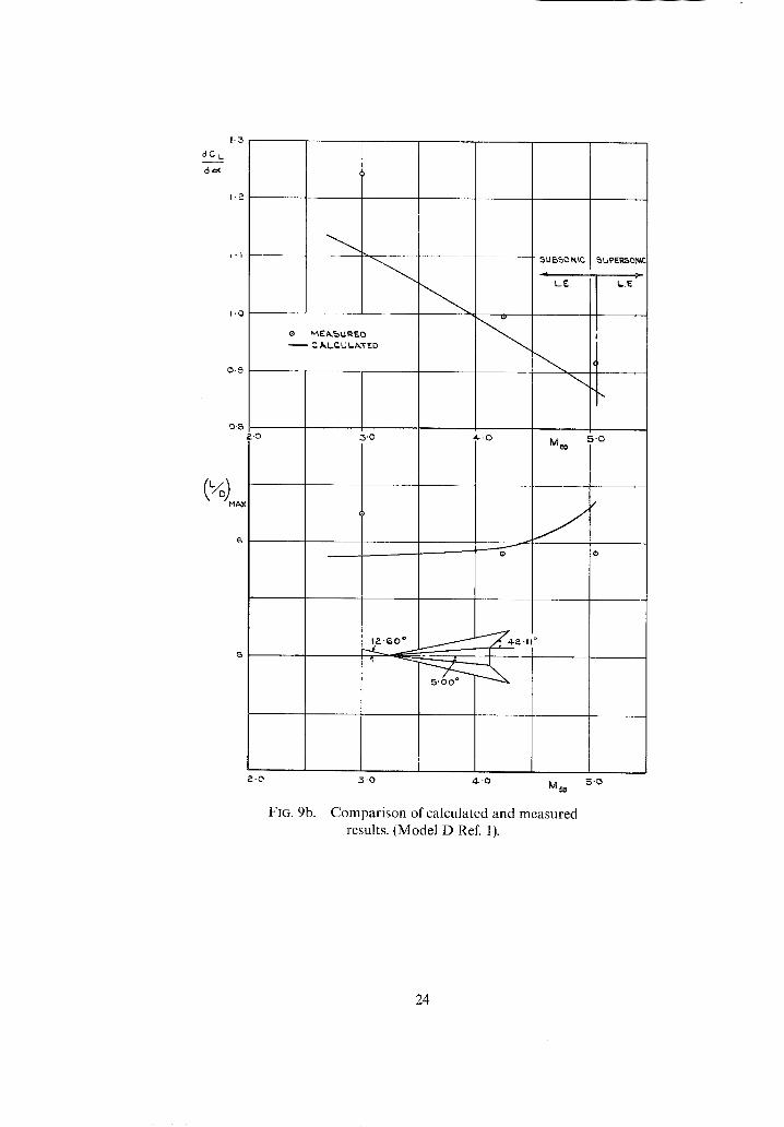
FIG. 9b.
3.o 4.-o M~
Comparison of calculated and measured results. (Model D Ref. 1).
5 - 0
24

0 ' 03
o
O. QI Z'0
O' 0 0 9
C o O
0.008
O- 007
O.OOG
O" 0O5 Z'O
G ° ' °~
0.08. [ - ~
0'01 ~ - - -
0 L----..-_-___ 2..0
3.0
3-0
r
4..0
\
4.-ID
m
4.0
Me= 5.0
®
\
5"0 M ~
®
\
M~ 5.0
FIG. 10a. Comparison of calculated and measured results. (Model ! Ref. 8).
25

dC L
doc
I '1
I . o "~
O.S
o M EA,~U~.ED
r"/S.LC.LIL/~'T E E)
0"8
~U~)QNIP. ~UPER~0NI,
LE
0 ' 7 :.o ,'~-' 0 M ~ 5"0
77'4"°
/
2 . 0 ,3-0 ,4.'0 M ~,
FIG. 10b. Comparison of calculated and measured results. (Model 1 Ref. 8).
5 . 0
26

tO
~ m
5 ['5
FIG. 11.
Oc.
S ~ 1
/
"3-a*l + ~ ~YMNgTRIG ~
A ~ Y M H [ T R I ~ 8( SYMMETRIC
CON FIGlU R/~TI ON$ HAV I¢
S/klViE iSi iOY V I I I . L I N E
I I I P-.-5 ~,'0 :3,5 4 - 0 i v l ~ 4 .5
Comparison ofasymrnetric and symmetric configurations (equal volume) for conical forebodies (no base drag).
h,.) o o
I!
~0
S O . B
FIG. 12.
/
) < I "
/ o.//.L-----'~'Ij + j / ÷ I
~0 °~ 4.2-1i ~ @4"° I ' 0 I'~.. I - 4
A..SY MMETRtC
hg¢o= 5 " 0 ~ "~/c = 0 , 0 2 xoe=
G c = S ° FOR T H E H~LF C.ON~ ~OOY "rF~AILINCa EDCa~ ~..N~L~ co
i r I ! <"~°, I .G I 'B ? - 0 ?-= ;:) ~ . ~ 2 ~ ~-'B ~ ' 0
A~PE:c.T I~.J~T|O
Variation of (L/D)m.×with aspect ratio at M~ = 5.0 for symmetric and asymmetric configura- tions (no base drag).

t ~
II
9 \
B
7
6 , ,
o 5 I 0
FIG. 13.
\
SYMMETRIC
Mc~
~c 0 5
\ l 0 0 c
Variation of (L/D)maxwith cone semi-angle and Mo~ for symmetric and asymmetric configura- tions (no base drag).

II
IO
FIG. 14.
M~, : 1'5
\ \
\
m 3
5
\
\
%
M~=2.5 M~=3"5
" 0 2 , 0 4 . 0 6 "0~-. . 0 4 . " 0 6 .0P. - 0 4 - " 0 g T "T" T
Effect of adding cylindrical extensions to conical half bodies on variation of (L/D)ma x with (no base drag).

Oa
12
I t
l 0
8
7 0 " 8
I r~ = S . 0
i l f WING A L O N ~:
i i
i I ' O 1'2 1.4 1"6
J f
~ J
J
f l
C O N S ] e c = 5 ° N O A F T E R B O D Y
D E C R E A S I N G ?
r ~. CONST.
V A R I A B L E CYL INORtCAL A F T E R B O D Y L E N G T H
1 . 8 - ~ ' 0 2 - 2 2 4 2 - 6 2 . 8 A S P E C T R A T I O
T = O-03B
FIG. 15. Comparison of varying 0c or adding cylindrical extensions to a conical half-body for variation of L/Dmaxwith aspect ratio (no base drag).
1'5 2-0 2.5 3"0 5'5 M~
# 0 4,5
FIG. 16. Comparison of asymmetric and sym- metric conical forebody configurations with and
without base drag.
32

10,5
I0 '0
(~-"/O) M #,.x
I
Mt~X
/ . . .-----
7 . 0 f
I'~ 8 ' 0 ~.'B ~'0 "~'5 4"0 4-'~ M~
FIG. 17. Comparison of symmetric and asym- metric configurations using a Sears-Haack body
(-c = 0-02, 0.04, 0.06).
33

| | t 1 \
Jo . ,~
(L/~,) . . . .
I
\
T 0 - 0 2
\ \
\ x
!
® Coolb
, ~ y M] NE.r talc L 5Y ~ I E T R t E.
I
:3 .5 4 , 5 Moo
~- × ~
- r = ~ . c ) 4
I 1 . 5 2 . 5 3 , 5 4 . 5
"7 , ,S \ \
\ \ \
t o \
(I ' /D) MI,~.× !: \
9 \ ~ " \
FIG. 18. Comparison of symmetric and asym- metric configurations for z = 0-02, 0-04, 0"06, using
a Sears-Haack body.
34

I Z
I I
I 0
\
\ . .
/
\ \
i I
/ I ~/~=o.o2
q"= 0 .04
-----... =
8
= 0 -5 " ] ~ - p=-~ , K,u.= K,,,. = I
7 - - ~ .~ . _ _ /
~=' J / /
5 1.5 Z.S 5.5 M
C~
FIG. 19. Trend comparisons between an asym- metric configuration (~ = 0.04) and slender wings.
/ / -
4-.5
35

A
A M,~,X.
I a,
A A
7- / Ae.x- AEN /
\ Ae.. N A M A ~ .
5 M 4- O0
L _ _ _ _ I I ~ J r I I --I
(c)
AEx- AEN /
Fi(;. 20. Variation of engine nacelle propertions and ways of increasing L/D for wing/nacelle com- binations.
36

"--1
12
t l
I 0
I I I t WlNq /M-ONE @OHIC L..EDEL'rA. 'E =0.0~)
/ t
S Y M M E R I C A L L Y PI.~.CEO NA.CELLE
7 1-5 2"0 ?__G 3'0 3-5
k ~ Y H M E T R I C A ~ NkCELLE
~LRc~D
M ~ 4-.0
FIG. 21. Comparison of symmetric and asymmetric engine nacelle/wing combinations.

\ . ~ j /
" I : _ 11
SCHEME (a)
---:L\---- 1
¢_
- b \ - - - ~ / / / - L ~ - - -
\
\ \
SCHEME (b)
¢_
FIG. 22a. Some possible ways of combining wing, volume and powerplant for max L/D.
38

A
SCHEME Cc~
SCHEME (d)
¢_
FIG. 22b. Some possible ways of combining wing, volume and powerplant for max L/D.
39

c~ ~.
m
-3 --4
F'
zt
...j-.
©
© _=,,
>
[..--,
t4,K~
f
,5 t '5 g .O
r
J
I j 5 Y M M . C O N r t ~ N .
"~= 0 . 0 4 - } "t:/c=O'OP-.
I --Z_
F-"-- ----.- __._ j
/ ~ " ~ - ~ - & 5'h" M M CONFI~N.
J i I & 5 3 ' 0 5 . 5
I
4 - - 0 4 . - 5 Me=,
FIG. 23. Comparison of symmetric and asymmetric configurations (wing, volume, and powerplant) for "c = 0-04.

Ro & IVL No° 3528
IC') Crown copvrtght 1968
Pubh~hed by H I ~ R M A J I , S I Y ' S ~ I A I I O N I ' R Y O I - H ( E
To be purchased from 49 High ttolborn, London w.c'.l 423 Oxford Street, l ,ondon w.I 13A ('a',tle Street, Edinburgh 2
109 St Mary Street, ( 'ardlff Bra~'enno~,e Street, Manche',ter 2
50 FaH't)lx Street, Bristol I 258 259 Broad Street, Bwmmgham I
7 1 I Lmenha[I Street, Belfast 2 or through any bookseller
i ................
i
R. & IVL No° 35281 ! ................
S.O. Code No 23 352~ !',',',',',::',',',',':? ! ..............