
H2B2VS D1 1 2 Updated State-of-the-Art V1...
91
H2B2VS D1 1 2 Updated State-of-the-Art V1 0.docx Page 1/91 H2B2VS D1.1.2 Updated report on the state of the art technologies for hybrid distribution of TV services Editor: Harri Hyväri (VTT) Reviewer: Pierre Sarda (NV) Authors: Lauri Lehti (Neusoft) Xavier Ducloux (TVN) Jesus Macias Peralta (ALU) Jean-Roger Roy (TDF) Raoul Monnier (TVN) Mickaël Raulet (IETR) Patrick Gendron (TVN) Aurélien Violet (SJ) Kagan Bakanoglu (VL) Wassim Hamidouche (IETR) Antti Heikkinen (VTT) Jarno Vanne (TUT) Daniele Renzi (EPFL) Burak Görkemli (TT) Pierre Sarda (NV) Ilkka Ritakallio (TEL) Tiia Ojanperä (VTT)
-
Upload
vuongquynh -
Category
Documents
-
view
226 -
download
0
Transcript of H2B2VS D1 1 2 Updated State-of-the-Art V1...

H2B2VS D1 1 2 Updated State-of-the-Art V1 0.docx Page 1/91
H2B2VS D1.1.2
Updated report on the state of the art technologies for hybrid distribution of
TV services
Editor: Harri Hyväri (VTT)
Reviewer: Pierre Sarda (NV)
Authors: Lauri Lehti (Neusoft) Xavier Ducloux (TVN) Jesus Macias Peralta (ALU) Jean-Roger Roy (TDF) Raoul Monnier (TVN) Mickaël Raulet (IETR) Patrick Gendron (TVN) Aurélien Violet (SJ) Kagan Bakanoglu (VL) Wassim Hamidouche (IETR) Antti Heikkinen (VTT) Jarno Vanne (TUT) Daniele Renzi (EPFL) Burak Görkemli (TT) Pierre Sarda (NV) Ilkka Ritakallio (TEL) Tiia Ojanperä (VTT)
H2B2VS D1 1 2 Updated State-of-the-Art V1 0.docx Page 2/91
EXECUTIVE SUMMARY Hybrid delivery of TV programs and services means that the main portion of the program is delivered via broadcast networks, i.e. satellite, cable or terrestrial networks, and additional portion is delivered via broadband network. Typical use case for hybrid delivery is such where TV program is delivered via broadcast network in 1080p resolution, and additional information, such as improved resolution or frame rate is delivered via broadcast network. Two program sources are received in the terminal capable of receiving hybrid delivery, synchronized according to the synchronization requirements, and viewed on display. This deliverable explains the state of art for the technologies required, when TV programs and services are delivered in hybrid networks. Specific technologies selected for the project are HEVC for video compression and MPEG-DASH for HTTP adaptive streaming. Broadcast technologies Broadcast networks including satellite, cable and terrestrial networks are used for delivering the main delivery of hybrid broadcast/broadband service. The use of satellite networks for broadcasting TV programs started in large scale when DVB-S standard. DVB-S technology uses MPEG-2 compression technology for video, and is typically used for broadcasting SD resolution programs. DVB-S2 standard introduced better bitrates with the help of improved error coding and modulation techniques. The main driver for DVB-S2 standard was push for higher resolutions and improved image quality. DVB-S2 and use of H.264 video compression technology enabled delivery of HD resolution TV programs via satellite broadcasting. DVB organization continues development of DVB-S2 standard with extensions (DVB-Sx) that enable new use cases, and improve the channel efficiency. Cable networks have been improved during last 15 years greatly with the introduction of two-way communication. This has enabled new services such as Video on Demand, and high-speed Internet connections. New Data over Coax technologies, which enable up to 10 Gbps downstream, and 1 Gbps upstream connections will be developed in the project. Terrestrial broadcast networks are using DVB-T and DVB-T2 technologies. DVB-T enables delivery of 3-4 HD resolution programs while using H.264 compression technology. With the use of DVB-T2 broadcast network and HEVC compression technology it’s possible to deliver 8 programs with the same bandwidth. Thus new technologies enable doubling the amount of programs delivered, or enable higher image sizes such as 2K and 4K resolutions. Broadband technologies Broadband networks carry multiservice traffic including audio, video, and data to homes with the minimum bandwidth of 1 Mbps. Many competing technologies exist for providing these services. The most mainstream of these include fiber, cable, DSL, mobile broadband, and WiMax. DSL has been the dominant technology for broadband with the market share of over 50% in 2012. It provides reasonable bandwidth with low costs. Fiber networks provide the best transmission capacity, but the cost of bringing fiber networks to each house is high. Cable networks exist in most areas, and new promising techniques are being developed for data transmission. Mobile broadband networks enable 1 Gbps download speed in optimal conditions. All these technologies are competing and complementing each other. Content delivery networks are able to handle large number of simultaneous connections that can be requested on the websites pages, video and audio players. This is achieved by caching the content within different layers in the network to avoid overloading the source server. Then, this content is delivered by numerous edges servers located as close as possible to the end-user. When end-user requests the content, he will get the content from the nearest or least loaded server in the network. The evolution of transmission protocols, video codecs, access networks and terminals requires support from CDN Compression HEVC compression technology is in the core of H2B2VS project. HEVC standard introduces new tools for video compression thus achieving up to 50% bitrate savings when compared to currently used H.264 standard. The standard includes algorithms for compression, but it also includes methods that enable efficient implementation of the codec. Especially Wavefront Parallel Processing (WPP) technique is an important feature, since it allows processing of compression in different processor cores thus enabling the compression of 4K resolution videos. H2B2VS project has

H2B2VS D1 1 2 Updated State-of-the-Art V1 0.docx Page 3/91
developed both HEVC encoders and decoders thus enabling full transmission chain from head-end to terminals. Transport layer Audio and video streaming over IP started in the 1990’s using RTP/UDP protocols. RTP/UDP based streaming solutions are still popular for IPTV services in managed networks, where operator can control the whole network from server to terminal. RTP/UDP based streaming method has many benefits: very good bandwidth utilization, only little amount of buffering is needed, support for trick modes such as play, rewind, etc. with low delay. In Internet networks RTP/UDP based streaming solutions are not working well due to no support for multicast addresses, lack of support or configuration needs in firewalls and routers, and variation in delays and available bandwidth. Due to the problems in RTP/UDP based streaming solutions, HTTP based streaming solutions have been developed. First solutions were based on file downloading or progressive downloading. Due to varying bandwidth in Internet, varying buffering requirements in client applications, and stalling video playback better technologies for HTTP based video streaming have been developed. HTTP Adaptive Streaming (HAS) solutions are most promising methods for HTTP based video delivery. There are several competing commercial solutions for HAS (Apple HTTP Live Streaming, Microsoft Smooth Streaming and Adobe HTTP Dynamic streaming), and several standardization activities as well. MPEG-DASH is a joint standard developed by MPEG and ISO organizations. The main characteristics of HAS solutions are:
• Content is encoded at different qualities generating different streams. This allows the client to use one or another depending on the available bandwidth.
• Streams are fragmented in chunks or segments of certain duration, i.e. 2 up to 10 Sec. Client can switch from one segment in one quality to the next segment in other quality seamlessly.
• All segments are stored as files in the Web server and the client can retrieve them with HTTP.
• A special description file, called the ’Manifest’ describes the channel in terms of bitrates, segments properties and URL’s needed to access all the segments.
• From the Manifest, client parses the number of available qualities in that channel and the URLs to access the segments.
• The client asks for segments of the appropriate quality and shows the content to the user. If the network conditions change the client can change in real time from one quality to another maintaining a continuous reproduction of the content.
MMT MPEG Media Transport (MMT) is a standard being developed in ISO/IEC. The purpose of this technology is to provide standardized methods for developing in-network intelligent caches located close to the users. It caches the content actively, and packetizes and pushes the content actively to the receivers. This technology is relevant in coming content centric networking architectures, and it’s also relevant for hybrid delivery schemes. MMT has been published as an international standard in spring 2014. Content protection Content protection is essential for content owners, since digital content can be copied without loss of quality. There are two types of protection needed for protecting the content in each case:
1. Proactive protection of content, 2. Reactive protection of content.
The first barrier targets direct attacks on the asset such as theft, alteration and replacement. The associated tools are based on encryption and cryptographic signature. Unfortunately, content can always leak. As a result, the second barrier is needed to attempt to limit the losses that are incurred. Combining these two methods provides the best protection for the content. Proactive content protection in broadcast networks is typically based on conditional access systems (CAS). CAS is specified by DVB-CA standardization organization for DVB broadcast networks. Content is encrypted with frequently changing control word. Control word in turn is encrypted with service key, which contains information about paid subscribers. On receiver side, set-top box includes a smart card, which is used for detecting the user. If user has rights for using the content, content will be unprotected, and played on display. Proactive content protection in broadband networks is mostly similar to broadcast networks, but there are few differences due to the use of generic computers as client devices instead of closed

H2B2VS D1 1 2 Updated State-of-the-Art V1 0.docx Page 4/91
systems like STBs used in broadcast environment. Digital Rights Management (DRM) protects the content delivered on broadband. DRM systems are fully software based, since they run on generic computers, and they use two-way communication for exchanging encryption keys. Key exchange is the most vulnerable portion of DRM systems, and methods for key exchange are key technologies for DRM companies. Thus there is very little public information available for those methods. Reactive content protection methods are useful for finding the source of content leakage, if content has been encrypted and shared for public. Digital watermarking technology has been developed for inserting imperceptible serial number within the audio or the video of the content before it is being distributed. This serial number can be used for finding the user who has leaked the content. With digital watermarking it’s possible to add information to audio or video streams in such a way that it’s not visible or audible to the user. Quality of Experience Quality of Experience (QoE) refers to the subjective quality perceived by the user when consuming audio-visual content. There are two basic approaches for assessing the QoE:
1. Subjective assessment, where evaluators assessing the quality of a series of short video sequences according to their own personal opinion,
2. Objective assessment, the quality of content is measured in an automatic, quantitative and repeatable way with software algorithms.
There are several tools for doing the objective assessment of content. Full reference methods such as Peak Signal to Noise Ratio (PSRN), or Structural SIMilarity (SSIM) can be used, when the original and distorted videos are available for metrics calculation. Reduced reference methods require certain features of original content to be transmitted to receiver side for metrics calculation. No-Reference methods do not require the original content data for metrics calculation. Thus it’s suitable for IP based video services, where the original content is not available for analysis. Full reference methods are most suitable for encoders or transcoders, where original and encoded or transcoded content is available for comparison. Most current objective quality assessment tools are based on RTP/UDP protocols, and are thus suitable for VOIP and video streaming services. HTTP based streaming services are becoming more and more popular, and there is need for developing quality assessment methods upon TCP protocols as well. Since traditional tools measure parameters like packet loss rate, delays, jitters, etc. they are not suitable for TCP traffic analysis. Parameters such as buffer underflow/overflow, filling rate or initial delay can be used for analysing the quality of content. Terminals for hybrid distribution Hybrid Broadcast Broadband TV (HbbTV) is an industry standard for hybrid content delivery, and Set-Top-Boxes for HbbTV exist already. STBs have broadcast and broadband network interfaces together with software and hardware capable of running applications specified by HbbTV standard. STBs are typically based on Linux operating system, which enables efficient development of applications for use cases defined in the project. Number of mobile terminals has increased rapidly, and it’s estimated to continue strong growth in the future as well. Utilizing mobile terminals such as smart phones and tablets as 2nd screen devices in connection with the main TV screen gives good possibilities for developing new applications and services. The dominant operating system in the mobile terminals is Android with over 70% market share in 2012. Second player in the field is Apple’s iOS having 14% market share. Mobile terminals typically have multiple network interfaces such as cellular and WLAN, and there is lot of computing power available in the devices. The coming broadcast possibilities in LTE networks utilizing eMBMS technology enable also hybrid delivery of multimedia streams to mobile devices. Typically there is also hardware support for video encoding and decoding, which enables producing and consuming of good quality video.

H2B2VS D1 1 2 Updated State-of-the-Art V1 0.docx Page 5/91
Table of Contents
Executive Summary ............................................................................................................ 2 1 Document history and abbreviations ................................................................................ 8
1.1 Document history .................................................................................................... 8 1.2 Abbreviations .......................................................................................................... 8
1 Introduction ............................................................................................................... 10 2 Networks ................................................................................................................... 11
2.1 Broadcast networks ............................................................................................... 11 2.1.1 Satellite networks ............................................................................................ 11 2.1.2 Cable networks ................................................................................................ 22 2.1.3 Terrestrial networks ......................................................................................... 24
2.2 Broadband network & CDN ...................................................................................... 32 2.2.1 Broadband networks ......................................................................................... 32 2.2.2 Content Delivery Networks ................................................................................ 38
3 Compression .............................................................................................................. 45 3.1 HEVC standard ...................................................................................................... 45 3.2 HEVC encoding ...................................................................................................... 46 3.3 HEVC decoding ...................................................................................................... 49
4 Transport layer ........................................................................................................... 52 4.1 Adaptive HTTP Streaming ....................................................................................... 52
4.1.1 Introduction .................................................................................................... 52 4.1.2 MPEG-DASH .................................................................................................... 54
4.2 MMT .................................................................................................................... 61 4.2.1 Content Model ................................................................................................. 62 4.2.2 Packetization ................................................................................................... 62 4.2.3 MMT in the Future Internet ................................................................................ 63 4.2.4 MMT potential future Use Cases ......................................................................... 63
5 Content protection, security ......................................................................................... 64 5.1 CAS ..................................................................................................................... 64
5.1.1 Proactive protection in Broadcast ....................................................................... 64 5.1.2 Conditional Access System CAS - the Big Picture .................................................. 65 5.1.3 Proactive protection in Broadband (Unicast, multicast) .......................................... 69 5.1.4 Broadcast Encryption ........................................................................................ 69 5.1.5 Stateful Key Hierarchies .................................................................................... 69
5.2 Forensic Watermarking ........................................................................................... 70 5.2.1 Introduction .................................................................................................... 70 5.2.2 Technology ..................................................................................................... 70 5.2.3 Initial commercial deployment: forensic watermark as a powerful deterrent ............. 71 5.2.4 Deployment of watermarking in the B2B deliveries ............................................... 72 5.2.5 Deployment of watermarking in the B2C deliveries ............................................... 72
6 Quality of Experience ................................................................................................... 74

H2B2VS D1 1 2 Updated State-of-the-Art V1 0.docx Page 6/91
6.1 QoS/QoE Assessment Methods ................................................................................ 74 6.2 Existing Tools for QoS/Client-side session monitoring ................................................. 75 6.3 Existing Tools for QoS/QoE Evaluation - Server/Network-side monitoring (probes) ......... 75 6.4 QoS/QoE Assessment for MPEG DASH-based services ................................................. 76
7 Terminals for hybrid distribution .................................................................................... 77 7.1 Fixed terminals ..................................................................................................... 77
7.1.1 HbbTV STB market ........................................................................................... 77 7.1.2 Overview of the Hbb TV standardization efforts .................................................... 77 7.1.3 A reference hardware architecture of a hybrid STB and HEVC decoding capability ..... 79 7.1.4 A reference software architecture of a hybrid STB and HEVC decoding capability ....... 80
7.2 Mobile terminals .................................................................................................... 82 7.2.1 Software Architecture ....................................................................................... 83 7.2.2 Connectivity .................................................................................................... 83 7.2.3 Screen ............................................................................................................ 84 7.2.4 Audio and video ............................................................................................... 84 7.2.5 Standardization efforts towards enabling hybrid delivery in LTE .............................. 86
8 Conclusions ................................................................................................................ 87 9 References ................................................................................................................. 88
Table of Figures
Figure 1 Satellite global coverage for C/Ku band (left) and multi-spot Ka (right) ....................... 12 Figure 2 QPSK Constellation ............................................................................................... 13 Figure 3 DVB-S2 modulations ............................................................................................. 15 Figure 4 DVB-S vs. DVB-S2 performances ............................................................................ 16 Figure 5. Achievable information rates in DVB-S2 for a 36 MHz transponder. ............................ 17 Figure 6. Evolution of DVB-S standards. .............................................................................. 18 Figure 7: DVB-S2 and DVB-S2X efficiency vs C/N for Lineal Channels ...................................... 18 Figure 8. New reduced roll-offs. .......................................................................................... 19 Figure 9. DVB-S2X with VCM for different video qualities. ...................................................... 20 Figure 10. Extensions for WBT – multi-carrier vs. single carrier ............................................... 20 Figure 11. Time slicing frame. ............................................................................................ 20 Figure 12. Generic Contribution and Distribution Architecture. ................................................ 21 Figure 13. DTH Satellite service .......................................................................................... 21 Figure 14. DTT Coverage extension via Satellite .................................................................... 21 Figure 15: Evolution of HFC cable networks .......................................................................... 22 Figure 16: Evolution of TELCO networks .............................................................................. 23 Figure 17: Evolution of All-IP networks ................................................................................ 23 Figure 18: Comparison of different Data over Coax technologies ............................................. 24 Figure 19 : DVB-T2 – Built partially on previous DVB systems ................................................ 25 Figure 20: Overlaps between DVB-T2 Base, DVB-T2 Lite and DVB-NGH ................................... 25 Figure 21 : Multi PLP Hybrid Broadcasting ............................................................................ 29 Figure 22 : Multi PLP – Resources allocation (1st example) ..................................................... 29 Figure 23: Multi PLP – Resources allocation (2nd example) ...................................................... 30 Figure 24 : Multi PLP – Common PLP generation ................................................................... 30 Figure 25 : Multi PLP – CBR and VBR schemes ...................................................................... 31 Figure 26: Worldwide broadband market share by technology Q4 2012 [3] .............................. 33 Figure 27: Average measured connection speed by country/region [4] .................................... 34 Figure 28: High broadband (> 10 Mbps) connectivity [4] ....................................................... 34 Figure 29: Maximum ADSL speeds depending on distance from exchange [5] ........................... 35 Figure 32: Examples of CDN Service Providers by category .................................................... 40 Figure 34: General architecture of a typical CDN ................................................................... 42
H2B2VS D1 1 2 Updated State-of-the-Art V1 0.docx Page 7/91
Figure 35 – Layers in a SHVC stream .................................................................................. 48 Figure 36: HTTP Adaptive Streaming example ...................................................................... 54 Figure 37: DASH Scope ..................................................................................................... 55 Figure 38: MPD hierarchical view ........................................................................................ 57 Figure 39: DASH profiles ................................................................................................... 59 Figure 40: MMT Functional Areas ........................................................................................ 62 Figure 41: CAS Overview - Head-end side ............................................................................ 66 Figure 42: CAS Overview - Receiver side ....................................................................... 67 Figure 43: Nagra CAS Overview ..................................................................................... 68 Figure 44: Psycho-acoustic masking .............................................................................. 70 Figure 45 Principle of content watermarking ......................................................................... 71 Figure 46: Exclusivity period of movies ................................................................................ 72 Figure 47: Functional components of a hybrid terminal .......................................................... 78 Figure 48 Components of a hybrid STB hardware architecture ................................................ 79 Figure 49 Block diagram of a chipset capable of a hybrid STB ................................................. 80 Figure 50: MHP reference model ......................................................................................... 81 Figure 51: An example of software architecture of a hybrid STB .............................................. 81 Figure 52: Growth of mobile terminals. ................................................................................ 82 Figure 53: Android operating system architecture ................................................................. 83 Figure 54: Combined broadcast and unicast protocol stack. .................................................... 86 Figure 55: Hybrid distribution architecture for DASH-based Live Services in LTE. ....................... 87
Table of Tables
Table 1 DVB-S performances .............................................................................................. 13 Table 2 DVB-S and DVB-S2 parameters for a 36 MHz transponder. ......................................... 16 Table 3 : DVB-T2 specifications .......................................................................................... 24 Table 4 : DVB-T and DVB-T2 features ................................................................................. 26 Table 5 : DVB-T and DVB-T2 profiles (fixed rooftop reception) – Studied French case ................ 27 Table 6 : DVB-T2 Disruptive profiles (fixed rooftop reception) ................................................. 28 Table 7 : Possible DVB-T2 profiles for Mobile and Portable reception ........................................ 28 Table 8 Top 10 countries in broadband subscription [3] ......................................................... 33 Table 9 Common DSL technologies ..................................................................................... 35 Table 10 Common wireless standards .................................................................................. 36 Table 11 Common mobile access standards .......................................................................... 37 Table 12 Toolset differences between HEVC, AVC, and MPEG-2 [6] .......................................... 46 Table 13 Average Shares of the Most Complex Encoding Stages of HM MP [9] .......................... 47 Table 14 RDC Summary of HEVC MP (HM 6.0) AND AVC HIP (JM 18.0) [9] ............................... 47 Table 15 Decoding time performance of the open source HEVC decoder OpenHEVC (based HM-10) ...................................................................................................................................... 50 Table 16 Worldwide Mobile Device Sales to End Users by Operating System in 3Q12 (Thousands of Units) ............................................................................................................................. 83 Table 17 Multimedia protocols in Android platform: ............................................................... 84 Table 18 Video encoding parameters in Android platform ....................................................... 85
H2B2VS D1 1 2 Updated State-of-the-Art V1 0.docx Page 8/91
1 DOCUMENT HISTORY AND ABBREVIATIONS 1.1 Document history
Version Date Description of the modifications 0.1 17.11.2014 Draft of ToC (VTT) 0.2 24.11.2014 Updated ToC (VTT) 0.3 8.2.2015 First integrated version 0.4 20.2.2015 Comments to integrated version 0.5 27.2.2015 D1.1.2 for review 0.6 05.3.2015 Review 1.0 13.3.2015 Final version
1.2 Abbreviations
1
16APSK ............... Amplitude and Phase-‐Shift Keying
4
4G .......... fourth generation of mobile phone mobile communication technology standards
4K ............ 4K horizontal resolution such as 3840x2160
8
8K ............ 8K horizontal resolution such as 7680x4320
A
ADC ............................ Asset delivery characteristics ADSL2 .............. Asymmetric digital subscriber line 2 AIT ............................. Application information table API .................... Application programming interface
B
B2C ......................................... Business to consumer BMFF .................................... Base media file format BSS ................................. Broadcast Satellite Service
C
C/N .......................................... Carrier to noise ratio CABAC ... Context adaptive binary arithmetic coding CBR ................................................ Constant bit rate CCN ................................ Content centric networking CDN .................................. Content delivery network CI Composition information CMMB ........ China multimedia mobile broadcasting
D
DASH ......... Dynamic adaptive streaming over HTTP dB .................................................................. Decibel DECE ........ Digital entertainment content ecosystem
Docsis .................. Data Over Cable Service Interface Specification
DRM ................... Digital rights management DSIS .................... Double stimulus impairment scale DSM-‐CC .......... Digital storage media command and control
DTH .................................................. Direct to home DTT ................................ Digital terrestrial television DVB-‐NGH .............. DVB -‐ Next Generation Handheld DVB-‐T2 ........... Digital Video Broadcasting – Second Generation Terrestrial
E
Eb No ........... Normalized measure of the energy per symbol to noise power spectral density
eMBMS ............................ LTE version of Multimedia Broadcast/Multicast Service
Es/No .... Energy per symbol to noise power spectral density
ETSI ......... European Telecommunications Standards Institute
F
FCC ............... Federal Communications Commission FDM ........................ Frequency division multiplexing FEC .................................... Forward error correction FME ............................ Fractional motion estimation FSS .......................................... Fixed Satellite Service FTTB ......................................... Fiber to the building FTTC ............................................... Fiber to the curb FTTH ............................................. Fiber to the home
H
H.264 ...... H.264/MPEG-‐4 Part 10 or AVC (Advanced Video Coding) video compression standard
H.265 ......................................................... See HEVC HDTV ........................................... High Definition TV HEVC ............................. High efficiency video coding

H2B2VS D1 1 2 Updated State-of-the-Art V1 0.docx Page 9/91
I
IDR ....... instantaneous decoding refresh access unit IETF .......... Internet engineering task force IME ................................. Integer motion estimation IP Internet Protocol IPTV ............................... Internet protocol television ISDN ........ Integrated Services Data Digital Network ISP ......................... Internet service provider ITU .......... International telecommunication
union
J
JND ................................... Just noticeable difference
L
LDPC ................................. Low Density Parity Check LHS .................................... Local harmonic strength LTE .................................. Long term evolution
M
Mbps ...................................... Mega bits per second MFN ................................. Multi-‐frequency network MMT ..................................... MPEG media transport MODCOD ............................. Modulation and coding MPD ....................... Media presentation description MPU ...................................... Media processing unit
O
OIPF ............................................... Open IPTV forum OSD ............................................. On-‐Screen Display
P
PLC ..................... Powerline communications PLP .............................................. Physical layer pipe POP ....................................... Point of presence PSI/SI ............. Program Specific Information/Service Information
PSNR ................................. Peak signal to noise ratio
Q
QoE ............................... Quality of experience QoS ................................................ Quality of service QPSK ........................ Quadrature phase-‐shift keying
R
RF ................................................... Radio frequency RS ............................ Reed-‐Solomon error correction RTP .............................. Real-‐time transport protocol RTSP .......................... Real-‐time streaming protocol
S
SAO ........................................ Simple adaptive offset SBTVD ............ Sistema Brasileiro de televisão digital SDSL ...... Symmetric digital subscriber line SDTV ..................................... Standard Definition TV SFN .................................. Single-‐frequency network SISO ................................................. Soft-‐in, Soft-‐out SMATV .............. Satellite Master Antenna Television SSIM .......................................... Structural similarity
T
TCP ............................ Transmission control protocol TDM ................................ Time division multiplexing TS .................................................. Transport stream TTL ................................................... Time to live
U
UDP .................................... User datagram protocol
V
VCM ............................. Variable Coding Modulation VDSL ................... Very high data rate digital
subscriber line VoD ............................................... Video on demand VQM ......................................... Video quality metric
W
WBT ................................... Wide Band Transponder

H2B2VS D1 1 2 Updated State-of-the-Art V1 0.docx Page 10/91
1 INTRODUCTION This is an updated version of State of the art document. The purpose of this document is to identify and study the current state-of-the-art for hybrid distribution of TV services. The document covers content transmission, content compression, and content protection technologies, as well as quality of service/experience methods, and terminals for hybrid distribution. The abovementioned technologies will be affected, when hybrid broadband/broadcast services will be developed in the project. This technological survey has been a basis for work package 2, where the impact of hybrid distribution in different parts of the delivery chain has been specified and implemented. Also use cases defined in WP1, and demonstrators implemented in WP3 have utilized the results of this deliverable.

H2B2VS D1 1 2 Updated State-of-the-Art V1 0.docx Page 11/91
2 NETWORKS
2.1 Broadcast networks
2.1.1 Satellite networks
Since the emergence of the first satellite networks, one of the driver applications for this type of solution has been the broadcast market. In particular, services such as Direct-To-Home (DTH) television or contribution/distribution links are typically associated as the core satellite communication business and thanks to the fast deployment, reduced infrastructure cost, wide coverage and especially high bandwidth offered by this type of network they are ideal for broadcasting high quality content such as HDTV, 3DTV and now UHDTV.
Technological improvements have also made it possible to develop other market solutions such as point-to-point links for corporate communications and more recently broadband Internet access both for fixed and mobile terminals.
2.1.1.1 Frequency bands
Current satellite broadcast services are mostly transmitted over Ku band (18/12 GHz), however, improvements in technology have made it possible for new satellites to start including a higher frequency band, Ka band (30/20 GHz).
C Band
- Frequency band: 4 - 6 GHz
- Transponder bandwidth: from 54 MHz to 72MHz.
- Single beam covering very large areas.
- Large antenna size
- Very robust against rain fades.
- Interference with radio links in certain frequencies.
- Applications: contribution/distribution, corporate.
Ku Band
It is the most widely used frequency band in current satellite broadcasting (and also other applications). Main characteristics are summarized below:
- Frequency band: 12 – 18 GHz
- Transponder bandwidth: from 33 MHz to 72MHz.
- Single beam covering very large areas.
- Small antenna size: For DTH typically between 60cm and 90cm. Up to 2.4m typically for professional links.
- Sensitive to rain fades but not as critical as in Ka band.
- Applications: DTH, contribution/distribution, corporate, VSAT, broadband Internet access.
Ka Band
The use of this part of the spectrum is not only a technological trend, but also a market requirement, since lower frequency bands are saturated and demand for more bandwidth and faster communications is continuously increasing.
The most significant advantages for using Ka band are the availability of spectrum and the possibility of providing faster communications and wider bandwidths. This is suitable, for instance, for providing internet over satellite but also, in a near future, for broadcast services. The main disadvantage is the sensitivity to weather conditions, particularly to rain attenuation.
The introduction of Ka band in satellite communications has enabled the design of new high power transponders with typical bandwidths of hundreds of MHz. With these new payloads, higher data rates are available and a more efficient spectrum use is possible.

H2B2VS D1 1 2 Updated State-of-the-Art V1 0.docx Page 12/91
Main characteristics of Ka Band:
- Frequency band: 20 – 30 GHz
- Transponder bandwidth: 200 – 500 MHz.
- Multi-spot beam configuration.
- Frequency re-use.
- Small antennas.
- Very sensitive to rain fade.
- Applications: until know the typical use case is for broadband Internet access. Will presumably be used in broadcast applications (already some examples exist, for instance in USA).
Typical global satellite coverage in Ku or C band and the multi-spot concept are shown in Error! Reference source not found..
Figure 1 Satellite global coverage for C/Ku band (left) and multi-spot Ka (right)
2.1.1.2 Standardization Satellite transmission via DVB-S (Digital Video Broadcast - Satellite) marked the beginning of digital broadcasting. It represented a very significant step forward with respect to previous analogue systems, allowing the transmission of more channels within the same bandwidth and using lower signal levels at the receiver. However, the performance of this system is not optimal. Its benefits are limited by the processing capabilities in domestic receivers as well as the coding and modulation knowledge available at that moment. The current state-of-the-art standard for satellite video broadcasting, DVB-S2, includes significant improvements on performance. In the next sections an overview of both alternatives is presented.
DVB-S DVB-S (Digital Video Broadcasting - Satellite) is the original satellite broadcasting system. The structure allows mixing a great number of video services, audio and data in the same frame.
H2B2VS D1 1 2 Updated State-of-the-Art V1 0.docx Page 13/91
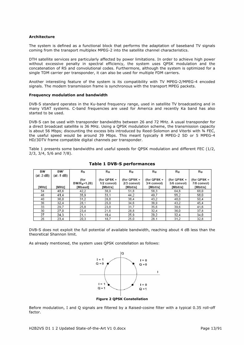
Architecture The system is defined as a functional block that performs the adaptation of baseband TV signals coming from the transport multiplex MPEG-2 into the satellite channel characteristics. DTH satellite services are particularly affected by power limitations. In order to achieve high power without excessive penalty in spectral efficiency, the system uses QPSK modulation and the concatenation of RS and convolutional codes. Furthermore, although the system is optimized for a single TDM carrier per transponder, it can also be used for multiple FDM carriers. Another interesting feature of the system is its compatibility with TV MPEG-2/MPEG-4 encoded signals. The modem transmission frame is synchronous with the transport MPEG packets. Frequency modulation and bandwidth DVB-S standard operates in the Ku-band frequency range, used in satellite TV broadcasting and in many VSAT systems. C-band frequencies are used for America and recently Ka band has also started to be used. DVB-S can be used with transponder bandwidths between 26 and 72 MHz. A usual transponder for a direct broadcast satellite is 36 MHz. Using a QPSK modulation scheme, the transmission capacity is about 56 Mbps; discounting the excess bits introduced by Reed-Solomon and Viterbi with ¾ FEC, the useful speed would be around 39 Mbps. This meant typically 8 MPEG-2 SD or 5 MPEG-4 HD/3DTV frame compatible digital channels per transponder. Table 1 presents some bandwidths and useful speeds for QPSK modulation and different FEC (1/2, 2/3, 3/4, 5/6 and 7/8).
Table 1 DVB-S performances
DVB-S does not exploit the full potential of available bandwidth, reaching about 4 dB less than the theoretical Shannon limit. As already mentioned, the system uses QPSK constellation as follows:
Figure 2 QPSK Constellation Before modulation, I and Q signals are filtered by a Raised-cosine filter with a typical 0.35 roll-off factor.

H2B2VS D1 1 2 Updated State-of-the-Art V1 0.docx Page 14/91
Application Scenarios Commercial requirements for DVB-S include multiprogramming services for digital television, bands for Fixed Satellite Service (FSS) and Broadcast Satellite Services (BSS). The system was defined to provide DTH (Direct to Home) for both final consumers like Satellite Master Antenna Television (SMATV) and TV distributions to cable and terrestrial networks, with the possibility of re-modulating. The system is suitable for different satellite bandwidth transponders. It is compatible with MPEG-2 services with synchronous transmission structure. The multiplex operation exploitation is flexible, allowing the use of transmission capacity for a variety of TV service configurations including sound and data. DVB-S standard was primarily developed for unidirectional television and radio broadcasting as they are the traditional services offered by satellite. Nevertheless, Point-to-Point and Point-to-Multipoint networks are also considered. As for the terminal to be used, fixed terminals are the preferred technology. They also work in mobile applications and services to ships, trains and large automobiles. The system is not suitable for handheld terminals. The restrictions come from the terminal and antenna size requirements.
DVB-S2
DVB-S standard generated a great interest for developing a new class of error correcting codes known as Turbo codes. These codes are based on the concatenation and interlacing of two simple convolutional codes (Low Density Parity Check - LDPC and BCH). The combination of these algorithms achieves higher performance, near 2 dB below with respect the DVB-S scheme. Following this line of progress, the DVB group initiated in 2003 a project aimed to define the second generation of digital satellite DVB-S2 for coding and modulation which could provide additional required bandwidth by the new challenges for the satellite networks (e.g HDTV services). Besides the improvements on error correcting, DVB-S2 changes the modulation used in DVB-S and DVB-DSNG into a new multilevel circular constellation of 32 symbols. It also reduces the Raised-cosine filter roll-off from 35% to 20%. The result is a 35% improvement in performance or 2.5dB in SNR with respect DVB-S. Technical characteristics DVB-S2 standard has been specified over three key concepts: improved transmission operation, total flexibility and reasonable complexity at receiver. Its performance benefits from the recent developments in channel coding (the adoption of LDPC codes) and modulation (QPSK, 8PSK, 16APSK and 32APSK). Error protection codes LDPC codes are easy decoding algorithms. They are based on simple operations such as comparison, addition or searching in a table. The main features are the following:
• Quasi-errors of 0.6 to 1.2 dB with respect Shannon limit. • Large LDPC code lengths (64800 bits for normal frame and 16200 bits for short ones). • Large number of iterations for decoding (about 50 iterations SISO (Soft-in, Soft-out)). • The presence of an outer code BCH concatenated (no interlacing).
Two levels of frame structure are defined: a physical level (with few bits of high signalling protection), and a base-band level (with a variety of signalling bits to allow maximum flexibility in the input signal adaptation). The coding rates 1/4, 1/3, 2/5, 1/2, 3/5, 2/3, 3/4, 4/5, 5/6, 8/9 and 9/10 are available depending on the selected modulation and system requirements. Coding rates 1/4, 1/3 and 2/5 have been introduced to operate in conjunction with QPSK under conditions of exceptionally poor link, where
H2B2VS D1 1 2 Updated State-of-the-Art V1 0.docx Page 15/91
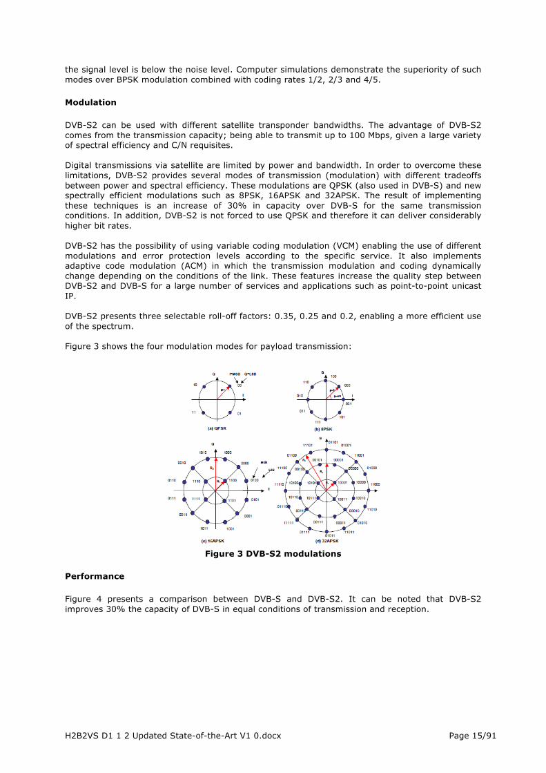
the signal level is below the noise level. Computer simulations demonstrate the superiority of such modes over BPSK modulation combined with coding rates 1/2, 2/3 and 4/5. Modulation DVB-S2 can be used with different satellite transponder bandwidths. The advantage of DVB-S2 comes from the transmission capacity; being able to transmit up to 100 Mbps, given a large variety of spectral efficiency and C/N requisites. Digital transmissions via satellite are limited by power and bandwidth. In order to overcome these limitations, DVB-S2 provides several modes of transmission (modulation) with different tradeoffs between power and spectral efficiency. These modulations are QPSK (also used in DVB-S) and new spectrally efficient modulations such as 8PSK, 16APSK and 32APSK. The result of implementing these techniques is an increase of 30% in capacity over DVB-S for the same transmission conditions. In addition, DVB-S2 is not forced to use QPSK and therefore it can deliver considerably higher bit rates. DVB-S2 has the possibility of using variable coding modulation (VCM) enabling the use of different modulations and error protection levels according to the specific service. It also implements adaptive code modulation (ACM) in which the transmission modulation and coding dynamically change depending on the conditions of the link. These features increase the quality step between DVB-S2 and DVB-S for a large number of services and applications such as point-to-point unicast IP. DVB-S2 presents three selectable roll-off factors: 0.35, 0.25 and 0.2, enabling a more efficient use of the spectrum. Figure 3 shows the four modulation modes for payload transmission:
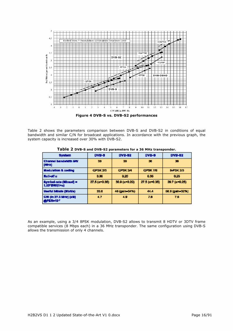
Figure 3 DVB-S2 modulations Performance Figure 4 presents a comparison between DVB-S and DVB-S2. It can be noted that DVB-S2 improves 30% the capacity of DVB-S in equal conditions of transmission and reception.
H2B2VS D1 1 2 Updated State-of-the-Art V1 0.docx Page 16/91
Figure 4 DVB-S vs. DVB-S2 performances Table 2 shows the parameters comparison between DVB-S and DVB-S2 in conditions of equal bandwidth and similar C/N for broadcast applications. In accordance with the previous graph, the system capacity is increased over 30% with DVB-S2.
Table 2 DVB-S and DVB-S2 parameters for a 36 MHz transponder.
As an example, using a 3/4 8PSK modulation, DVB-S2 allows to transmit 8 HDTV or 3DTV frame compatible services (8 Mbps each) in a 36 MHz transponder. The same configuration using DVB-S allows the transmission of only 4 channels.

H2B2VS D1 1 2 Updated State-of-the-Art V1 0.docx Page 17/91
Figure 5. Achievable information rates in DVB-S2 for a 36 MHz transponder. Applications The most typical modulations for broadcast applications are QPSK and 8PSK. They can be used for nonlinear transponders bringing them close to saturation. For some specific applications with multipath satellites, 16APSK provides extra spectral efficiency with requirements of linearity limited by the use of a pre-distortion scheme. 32APSK mode is primarily used for professional applications. It can also be used for broadcasting but requires a high level of C/N availability and the adoption of advanced methods of pre-distortion in the up-link station to minimize the effect of transponders nonlinearity. 16APSK and 32APSK constellations are optimized to operate on non-linear transponders, however, their performance in linear channels are respectively comparable with 16QAM and 32QAM. All modes are appropriate for quasi-linear channel satellites with FDM (Frequency Division Multiplex). On the other hand, the introduction of two FEC code block lengths (64800 and 16200) was dictated by two competing needs: the need to improve the value of C/N for large block lengths and the increasing latency in the modem. Therefore, for non-critical applications (such as broadcasting) the long frames are the best solution. Shorter frames are more efficient when small packets of information must be sent immediately by the broadcaster, being the case of interactive applications.
DVB-S2x
Bandwidth efficiency has always been the obsession of network operators and service providers. In that sense, satellite infrastructure has been historically a good example of how broadcast services could be transmitted efficiently and easily to global audiences. One of the key of this success are satellite broadcasting systems DVB-S and DVB-S2 that have become worldwide standards adopted in several applications such as DTH (Direct to Home), professional contribution services (news gathering), IP-trucking and broadband access via satellite.
After ten years of success on the market, the DVB decided to update the standard, adding new technologies and extending the capacities of the DVB-S2 to other applications maintaining the reference architecture. DVB-S2X is the result of extensive work for more than two years including manufacturers, operators, and services providers of the different market segments of DVB ecosystem.
Since the end of 2011, DVB groups CM-BSS and TM-S2 worked to define DVB-S2x with two main objectives: improving the spectral efficiency (bits/Hz) of the current standard and adapting it to the new use cases and challenges of the satellite industry, such as mobility, Ka band platforms or wide band transponders (WBT).
In March 2014 DVB-S2x was published as ETSI EN 302 307 part 2. The specification supports a much wider range of C/Ns, providing both much higher spectral efficiencies for professional applications such as contribution links and very low C/Ns for mobile environments.
H2B2VS D1 1 2 Updated State-of-the-Art V1 0.docx Page 18/91
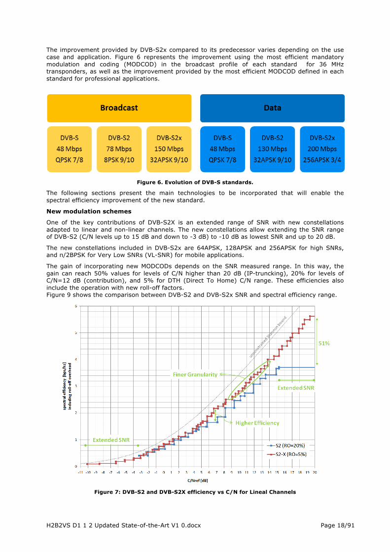
The improvement provided by DVB-S2x compared to its predecessor varies depending on the use case and application. Figure 6 represents the improvement using the most efficient mandatory modulation and coding (MODCOD) in the broadcast profile of each standard for 36 MHz transponders, as well as the improvement provided by the most efficient MODCOD defined in each standard for professional applications.
Figure 6. Evolution of DVB-S standards.
The following sections present the main technologies to be incorporated that will enable the spectral efficiency improvement of the new standard.
New modulation schemes
One of the key contributions of DVB-S2X is an extended range of SNR with new constellations adapted to linear and non-linear channels. The new constellations allow extending the SNR range of DVB-S2 (C/N levels up to 15 dB and down to -3 dB) to -10 dB as lowest SNR and up to 20 dB.
The new constellations included in DVB-S2x are 64APSK, 128APSK and 256APSK for high SNRs, and π/2BPSK for Very Low SNRs (VL-SNR) for mobile applications.
The gain of incorporating new MODCODs depends on the SNR measured range. In this way, the gain can reach 50% values for levels of C/N higher than 20 dB (IP-truncking), 20% for levels of C/N=12 dB (contribution), and 5% for DTH (Direct To Home) C/N range. These efficiencies also include the operation with new roll-off factors. Figure 9 shows the comparison between DVB-S2 and DVB-S2x SNR and spectral efficiency range.
Figure 7: DVB-S2 and DVB-S2X efficiency vs C/N for Lineal Channels

H2B2VS D1 1 2 Updated State-of-the-Art V1 0.docx Page 19/91
FEC granularity
Improvement in FEC granularity, though it has no direct impact in spectral efficiency it does impact indirectly. The difference between adjacent Es/No or Eb/No modcods in DVB-S2 is, in some cases, more than 1 dB. This limits the possibilities for the service provider or network operator in selecting the most appropriate FEC for the required quality of service, forcing in most cases to choose modcods more robust than necessary. The increase in the number of modcods will enable to better adjust these to the particular service.
Roll-off factor improvements
The roll-off factor defines how much more bandwidth the filter occupies than that of an ideal "brick-wall" filter, whose bandwidth is the theoretical minimum Nyquist bandwidth. Roll-off limits the bandwidth assigned to each carrier following the formula:
( ) SymbolRateOffRollBW ⋅−+= 1
Minimum roll-off in DVB-S2 is 0.2, however, manufacturers of ground segment satellite technology (modulators/demodulators) have been improving equipment to allow more abrupt filtering and, thus similar to the ideal filter. For DVB-S2x roll-off factors of 0.15, 0.1 and down to 0.05 have been specified. This allows reducing the carrier spacing so increasing spectral efficiency.
Figure 8. New reduced roll-offs.
The gain provided by smaller roll-off is meaningful for multicarrier scenarios such as professional services and DSNG but not so much in the single carrier per transponder case such as some data networks and, mainly, DTH services.
Variable Coding Modulation
This functionality allows different levels of protection in a frame by frame basis which could permit, for example, to adequate the transmission efficiency based on weather conditions or performance. This allows associating different levels of protection to SD, HD or 4K services ensuring the service scalability at a DVB frame level.
DVB-S2
DVB-S2 extensions

H2B2VS D1 1 2 Updated State-of-the-Art V1 0.docx Page 20/91
Figure 9. DVB-S2X with VCM for different video qualities. Channel bonding
For DTH reception, using multi-tuner Set-Top-Boxes, DVB-S2X allows the transmission of a Transport Stream mixing the capacity of up to three transponders so that the operator could further benefit from the gain of statistical multiplexing. .The use of Channel Bonding is particularly interesting for UHDTV broadcasting which requires high capacity (18 Mbps using H265) so that the number of services per transponder is dramatically reduced. Channel Bonding will allow levels of HD multiplexing in TS with UHDTV that means gains around 15%.
DVB-S2 extension for WBT (Wide Band Transponders)
This first system improvement was approved independently in July 2012 and introduced in the standard as Annex M to norm EN202307 (1). This annex arises with the need of updating the system for transponders with high bandwidth (around 250-500 MHz). Ideally, to use the maximum capacity of a transponder, it should be operated with a single carrier so that the transponder output back-off is reduced (Figure 10). However, the complexity of the receiver for demodulating high symbol rates, FEC decoding and filtering of such carriers greatly limited the development in this field.
Figure 10. Extensions for WBT – multi-carrier vs. single carrier
Because of this, TM-S2 proposed a solution based on the Time-Slicing concept already used in DVB-H, and in which several “virtual carriers” are created within a big carrier occupying all the transponder bandwidth. Receivers demodulate the PL-Header and select only the slice of interest discarding the rest, therefore reducing significantly the receiver complexity. This time-slicing concept is shown in Figure 11.
Figure 11. Time slicing frame.
2.1.1.3 Satellite Broadcasting Solutions
Within the broadcasting market, satellite links are used for multiple purposes:
Contribution: transmission of content from earth stations, fixed or transportable, to other earth stations, usually fixed, for further processing (Figure 12). Distribution: content transmission from fixed central earth station to terrestrial network head-ends. For its subsequent distribution to end-users via DTT, cable, fibre, etc. (Figure 12) DTH: Direct-To-Home service where content is directly broadcasted to end-users from the teleport (Figure 13). DTT Coverage Extension: For DTT to reach 100% population, a solution based on satellite is used for example in Spain. Using the appropriate encryption, the same signal distributed to DTT towers may be received directly by the end user as shown in Figure 14.
OBO
OBO

H2B2VS D1 1 2 Updated State-of-the-Art V1 0.docx Page 21/91
Figure 12. Generic Contribution and Distribution Architecture.
Figure 13. DTH Satellite service
Figure 14. DTT Coverage extension via Satellite
H2B2VS D1 1 2 Updated State-of-the-Art V1 0.docx Page 22/91
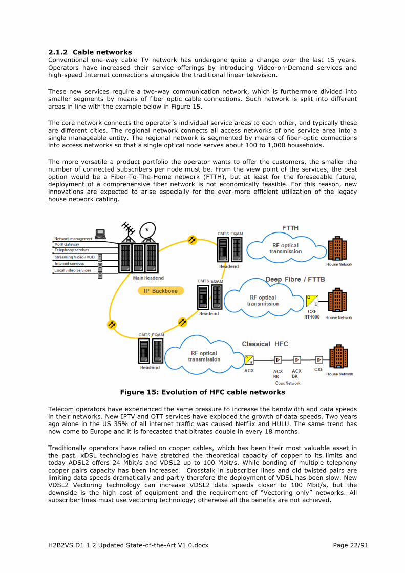
2.1.2 Cable networks Conventional one-way cable TV network has undergone quite a change over the last 15 years. Operators have increased their service offerings by introducing Video-on-Demand services and high-speed Internet connections alongside the traditional linear television. These new services require a two-way communication network, which is furthermore divided into smaller segments by means of fiber optic cable connections. Such network is split into different areas in line with the example below in Figure 15. The core network connects the operator’s individual service areas to each other, and typically these are different cities. The regional network connects all access networks of one service area into a single manageable entity. The regional network is segmented by means of fiber-optic connections into access networks so that a single optical node serves about 100 to 1,000 households. The more versatile a product portfolio the operator wants to offer the customers, the smaller the number of connected subscribers per node must be. From the view point of the services, the best option would be a Fiber-To-The-Home network (FTTH), but at least for the foreseeable future, deployment of a comprehensive fiber network is not economically feasible. For this reason, new innovations are expected to arise especially for the ever-more efficient utilization of the legacy house network cabling.
Figure 15: Evolution of HFC cable networks
Telecom operators have experienced the same pressure to increase the bandwidth and data speeds in their networks. New IPTV and OTT services have exploded the growth of data speeds. Two years ago alone in the US 35% of all internet traffic was caused Netflix and HULU. The same trend has now come to Europe and it is forecasted that bitrates double in every 18 months. Traditionally operators have relied on copper cables, which has been their most valuable asset in the past. xDSL technologies have stretched the theoretical capacity of copper to its limits and today ADSL2 offers 24 Mbit/s and VDSL2 up to 100 Mbit/s. While bonding of multiple telephony copper pairs capacity has been increased. Crosstalk in subscriber lines and old twisted pairs are limiting data speeds dramatically and partly therefore the deployment of VDSL has been slow. New VDSL2 Vectoring technology can increase VDSL2 data speeds closer to 100 Mbit/s, but the downside is the high cost of equipment and the requirement of “Vectoring only” networks. All subscriber lines must use vectoring technology; otherwise all the benefits are not achieved.

H2B2VS D1 1 2 Updated State-of-the-Art V1 0.docx Page 23/91
In the Telecom world network structure is more star-shaped and the key issue is the capacity of existing lines. Deep fiber (FTTB / FTTC /FTTH) is also the common trend. In new residential areas fiber is often coming to cellar through Ethernet switch and subscribers are connected to the switch with CAT 5/6 cable. The problem comes from old buildings and areas where it is very expensive to replace existing cables. The evolution of TELCO networks is presented in Figure 16.
Figure 16: Evolution of TELCO networks
If cable TV network has changed radically in last 15 years, what can be expected in next 15 years? Video-on-Demand and videocassette rental business are soon in internet. Most TV and radio stations are available on their Internet sites. Video and audio will be over IP sooner or later. Most of information will be over IP. Fiber and Ethernet will come closer and closer to the customers, but the final obstacle is the last part of the network. Renovation of the subscriber networks or FTTH is in most cases too expensive. Networks will be more and more based on Metro Ethernet and local data over coax, xDSL and Ethernet baseband technologies (Figure 17).
Figure 17: Evolution of All-IP networks

H2B2VS D1 1 2 Updated State-of-the-Art V1 0.docx Page 24/91
FTTH is the ultimate solution, but often too expensive to implement. Coaxial antenna network has the required capacity and it exists in many places. There are several data over coax “last mile” technologies like DOCSIS 3.0 based C-DOCSIS, EPoC, MoCA and powerline based technologies (IEEE P1901 and G.hn) (Figure 18), but DOCSIS (Data Over Cable Service Interface Specification) has gained the dominant role in most market areas. The new DOCSIS 3.1 standard will increase the capacity 50% being 10 Gbit/s downstream and 1 Gbit/s upstream. DOCSIS is the first candidate for data over coax networks and this is a promising solution in local IP connections.
Figure 18: Comparison of different Data over Coax technologies
2.1.3 Terrestrial networks
2.1.3.1 Generalities This chapter does not describe how DVB-T2 works. The aim is more to highlight what could be interesting or impacting in the context of the H2B2VS project. Detailed features of the DVB-T2 system can be found in ETSI standards, see table below:
Table 3 : DVB-T2 specifications
Current terrestrial broadcast networks are still mainly based on DVB-T technology. However with the availability of DVB-T2 since 2008, terrestrial broadcast network quickly evolve toward this new version of the standard. Some countries which have not started DTT yet, choose to build their terrestrial networks on a DVB-T2 basis. For others countries, a few existing DTT networks slowly migrate from DVB-T to DVB-T2, and new DTT networks use directly DVB-T2.
Star and Cascade
MoCA 2.0
DOCSISCATV
FM
70dB
2013
MoCA
400/800MbpsShared
Bypass needed
Star and Cascade
G.hn
(DOCSIS)CATV(FM)
70dB
2012
ITU-T
600MbpsShared
Bypass needed
Network topologies
Technology
Service co-existance
Link budget
Availability
Standardisation organisation
CoaxThroughput
Amplifiers on signal path
Star and Cascade
IEEE P1901
CATVFM
70dB
Yes
IEEE
500MbpsShared
Bypass needed
GoodGoodIngress Robustness Good
Star and Cascade
MicroDOCSIS 3.0
DOCSISCATV
FM
40dB
2012
Cablelabs
160Mbps US/400Mbps DS
Shared
Active return path amps, no bypass needed
Fair
Star only
BasebandEthernet
CATV
20dB
2011
-
100Mbps dedicated
Cannot exist
Excellent
Star and Cascade
EPON over Coax
DOCSISCATV
FM
Same as DOCSIS
Unknown
IEEE 802.3Ethernet
Working Group
Same as DOCSIS
Active return path amps, no bypass needed
Poor
Star and Cascade
HPNA 3.1
CATVFM
40dB
Yes
ITU-T discontinued
200Mbps Shared
Bypass needed
Average

H2B2VS D1 1 2 Updated State-of-the-Art V1 0.docx Page 25/91
One of the main reasons is that DVB-T2 provides higher capacities than DVB-T (better spectrum efficiency), for the same amount of radiated power. DVB-T2 is an efficient medium for the carriage of HDTV services, and is currently associated to the H.264 codec (H.265 in a near future).
Picture below shows how DVB-T2 is born, and the related legacy with previous DVB systems.
Figure 19 : DVB-T2 – Built partially on previous DVB systems
As depicted, there is the main DVB-T2 standard and two others (DVB-T2 Lite and DVB-NGH) which are mostly oriented for mobile or nomadic reception. The main DVB-T2 standard is often called "DVB-T2 base". It is a complete toolbox, from which other recent standards are derived. For a better understanding, please refer to picture and information hereafter:
Figure 20: Overlaps between DVB-T2 Base, DVB-T2 Lite and DVB-NGH
• DVB-T2 Lite is a large subset from DVB-T2 Base, with a few extensions allowing a better RF robustness.
• DVB-T2 Lite is fully compatible with DVB-T2 NGH (New Generation Handheld)

H2B2VS D1 1 2 Updated State-of-the-Art V1 0.docx Page 26/91
• DVB-T2 Lite and DVB-NGH are limited to 4 Mbit/s per PLP, in order to limit the hardware complexity at terminal level.
• DVB-NGH targets multimedia services and is full IP oriented, including interaction with broadband mobile (4G)
A mixture of DVB-T2 Base with DVB-T2 Lite or DVB-NGH services is possible in the same RF channel. In this situation, the network architecture is generally driven by the most stringent use-case. However terrestrial networks currently convey only DVB-T2 base services (SDTV, HDTV). There are not yet commercial devices, compliant with DVB-T2 Lite or DVB-NGH.
There are common features between DVB-T and DVB-T2 especially in RF field, in order to remain compatible at network architecture level. For DVB-T2, new features have been added in order to cope with requirements not correctly addressed by DVB-T. The following table gives an overview of these features.
Table 4 : DVB-T and DVB-T2 features
SFN or MFN topology network has an impact for the management of the broadcast content. Single Frequency Network (SFN) allows the use for several transmitters of the same frequency channel. This topology network is often considered for the coverage of wide areas, as it is less consuming for frequency resources. However three fundamental conditions have to be fulfilled:
• Same broadcast content in the overall area, whatever is the stream transport mode (single stream or multi stream).
• Same bit rate in the overall area with tailored delays for each transmitter, according to guard interval values and targeted area to cover.
• High accuracy and stability for the frequency channel (respectively better than 1.10-10 and 1.10-7 over three months).
2.1.3.2 Fixed antenna rooftop reception mode
For existing DVB-T networks, the most common reception mode is the fixed rooftop antenna one (excepted in Germany which targets portable reception). Following this situation, two basic scenarios can be considered for the introduction of DVB-T2, see table hereafter:
H2B2VS D1 1 2 Updated State-of-the-Art V1 0.docx Page 27/91
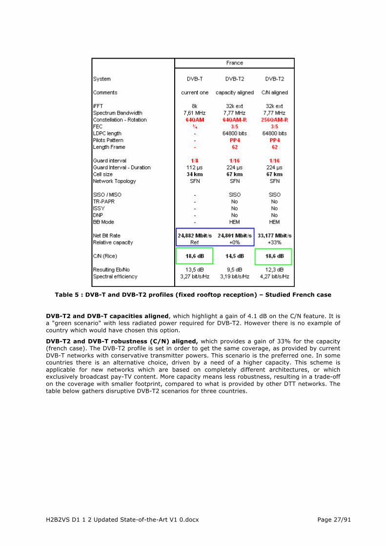
Table 5 : DVB-T and DVB-T2 profiles (fixed rooftop reception) – Studied French case
DVB-T2 and DVB-T capacities aligned, which highlight a gain of 4.1 dB on the C/N feature. It is a "green scenario" with less radiated power required for DVB-T2. However there is no example of country which would have chosen this option.
DVB-T2 and DVB-T robustness (C/N) aligned, which provides a gain of 33% for the capacity (french case). The DVB-T2 profile is set in order to get the same coverage, as provided by current DVB-T networks with conservative transmitter powers. This scenario is the preferred one. In some countries there is an alternative choice, driven by a need of a higher capacity. This scheme is applicable for new networks which are based on completely different architectures, or which exclusively broadcast pay-TV content. More capacity means less robustness, resulting in a trade-off on the coverage with smaller footprint, compared to what is provided by other DTT networks. The table below gathers disruptive DVB-T2 scenarios for three countries.

H2B2VS D1 1 2 Updated State-of-the-Art V1 0.docx Page 28/91
Table 6 : DVB-T2 Disruptive profiles (fixed rooftop reception)
2.1.3.3 Portable and mobile reception modes
These use-cases are more demanding than for the previous mode: lower antenna gain, location at 1,50m ground level for reception, and optionally mobility. The link budget must be revisited for taking into account these conditions and reception margins have to be increased. As the number of transmitters in the network is closely driven by C/N criteria, it means for economic reasons that C/N values can't exceed 13 dB for mobile and stationary reception and 16 dB for portable reception.
Table 7 : Possible DVB-T2 profiles for Mobile and Portable reception
The above table summarizes two indicative profiles for mobile and portable reception. Alternative profiles remain possible, depending of the required cell size or acceptable network topology.

H2B2VS D1 1 2 Updated State-of-the-Art V1 0.docx Page 29/91
Therefore the proposed values are a good and realistic basis for such projected scenarios.
2.1.3.4 PLP use and management
All capacities defined for the previous profiles are intended to be used for one PLP. This stand-alone PLP scheme is also called "mode A". It has been widely chosen at the launching of DVB-T2, because multi PLP gateways and suited chipsets on the reception side were not yet available.
The single PLP mode is comparable to DVB-T broadcasting. All the audio, video and data packets (PES) are conveyed in the same MPEG transport stream. Consequently the robustness level defined by constellation scheme and CR value, apply to all services in a same manner.
Alternatively multi PLP broadcasting which is called "mode B" allows different scenarios. The picture below depicts one of them.
Figure 21 : Multi PLP Hybrid Broadcasting
Each data stream is processed through an independent container (PLP). Major steps and features are the following:
• Frequency and time interleaving process, FEC coding and constellation mapping (xQAM) • Broadcasting of different kind of services (HDTV, SDTV, mobile TV) on the same frequency
channel. Alternatively each PLP can convey a same type of content (e.g. HDTV) under different labels: national, regional or local content.
This scenario enables several use-cases with suited coverage for the same frequency channel, thanks to independent robustness and payload capacities. A typical resources allocation mechanism for two PLP is shown below.
Figure 22 : Multi PLP – Resources allocation (1st example)

H2B2VS D1 1 2 Updated State-of-the-Art V1 0.docx Page 30/91
Following the same operating principle, the overall time resource can be shared with several PLP set at a common robustness level (common use-case), as depicted in the example below.
Figure 23: Multi PLP – Resources allocation (2nd example)
Each PLP carries a complete and independent MPEG transport stream (TS1, TS2, TS3), with its own signalling data. At the reception side the wanted PLP is selected and processed, in order to retrieve all data. This is the most common encountered situation, when Multi PLP broadcasting is used.
In order to improve the efficiency, DVB-T2 has introduced a "common PLP". This special PLP is dedicated for the carriage of all common signalling data, in order to avoid PSI/SI redundancy in each PLP. It means that the receiver must be able to process two PLP at the same time: common PLP and a selected PLP (mandatory requirement from the standard).
The common PLP is somewhat tricky to generate, as it requires time synchronization at TS level (see picture below).
Figure 24 : Multi PLP – Common PLP generation
Due to its small time spreading, it is highly recommended to increase the robustness of the common PLP. Moreover because specific PSI/SI data is still necessary in each PLP, final gain brought by a common PLP remains moderate. The effectiveness of a common PLP will be proportional to the number of related PLP, and the number of services carried by each of them. At present date, there are no DVB-T2 practical cases for which the common PLP is used.
According to iFFT size and what is declared at physical layer level (post signalling L1), the maximal number of PLP can reach 255. Therefore it is a theoretical limit, as a high number of PLP reduces the resource allocation per PLP, and requires extending the length of super-frame in order to get

H2B2VS D1 1 2 Updated State-of-the-Art V1 0.docx Page 31/91
asuitable time diversity. Generally DVB-T2 gateways (mostly located at the head-end) are able to process up to eight MPEG transport stream, and current multi PLP broadcasting involves three to four PLP.
There are other features for PLP, listed below. Bold lines refer to mostly adopted configuration.
• Type 1: PLP data are transmitted on a continuous basis in each DVB-T2 frame, i.e. one slice per DVB-T2 frame. Best way for PLP substitution, and power consumption management (handheld terminal)
• Type 2: PLP data are transmitted on two or more sub-slices in each DVB-T2 frame. Provides better time diversity.
• CBR PLP: constant value for the instantaneous bit rate of each PLP. Mandatory scheme for PLP substitution. Don't confuse: PLP content can be encoded on a CBR or VBR basis (statistical multiplexing per PLP).
• VBR PLP: optimized value for the instantaneous bit rate of each PLP. PLP content is on a VBR basis (statistical multiplexing at frame or super-frame level). Not suited for PLP substitution.
Figure 25 : Multi PLP – CBR and VBR schemes
2.1.3.5 Number of carried services
It is interesting to have some benchmarks regarding the number of conveyed services for DVB-T2. However these figures remain indicative due to continuous improvements on encoding and statistical multiplexing processes. The table hereafter summarizes for the studied french case (see 2.1.3.2) what can be expected today.
Table 8 : capacities according to chosen combination
The combination of DVB-T2 with H264 codec is the current situation. The use of HEVC codec will be the rule for the launching of new DVB-T2 networks in two or three years. It means also that HDTV in its basic video format (1080i or 720p) will be extensively used instead of SD format (576i).
2.1.3.6 DVB-T2 Timestamp Information
All content data are put in T2-MI packets which are encapsulated in a MPEG-2 transport stream, thanks to the T2-MI gateway (equipment generally located at the network head end). This stream is intended to be used through the contribution network for feeding transmitting sites (DVB-T2

H2B2VS D1 1 2 Updated State-of-the-Art V1 0.docx Page 32/91
modulators). As it includes a part of "in-band" signaling, it is not broadcast in its original format to the end-users.
There is a special T2-MI packet (0x20) built by the T2-MI gateway, which carries absolute or relative timestamp information. These time references are used for the scheduling of PLP broadcast, and also for the SFN synchronization at modulator level. However these time data are not propagated through the DVB-T2 modulators to the end-users.
For special SFN purposes, an optional T2-MIP packet (MPEG-TS, 188 bytes) can be optionally inserted by the T2-MI gateway in the broadcast DVB-T2 signal. When doing this it is possible to retrieve the same timestamp information at user-level, such as carried by the T2-MI packet. The DVB-T2 timestamp mechanism is fully described in the ETSI 102773 standard (Modulator Interface T2-MI).
Figure 25 - DVB-T2 Timestamp Payload
2.2 Broadband network & CDN 2.2.1 Broadband networks Broadband networks can be defined as networks that carry multiservice traffic including audio, video, and data; at a considerably faster speed than narrowband technologies (e.g. dialup, ISDN). While there is no universal consensus on the broadband speed threshold, FCC defines basic broadband service as supporting a minimum of 1 Mbps network bandwidth [1]. Moreover, Recommendation I.113 of the ITU Standardization Sector (ITU-T) defines broadband as a transmission capacity that is faster than primary rate ISDN, at 1.5 or 2.0 Mbps. There are many different technologies that enable broadband connection. The most mainstream of these include fiber, cable, DSL, mobile broadband, and WiMax. The competition among these technologies to offer broadband internet service exists primarily in providing last mile service, because the major long distance wires that comprise the Internet backbone around the world are primarily made out of optical fiber. The ultimate goal for broadband providers today is to be able to offer voice, data, and video over one network which is known as a "triple play."
2.2.1.1 Market Overview Latest broadband and IPTV figures published by the Broadband Forum [2] show a significant increase in broadband connections, with 8.6% annual growth. Fiber deployments grew faster than other access technologies, where FFTx/VDSL2 hybrid deployments play a key role. 50 million new users worldwide have subscribed to broadband in 2012, totalling to 643,770,042 broadband subscribers around the world by end of 2012 [3].
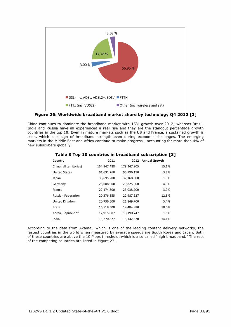
H2B2VS D1 1 2 Updated State-of-the-Art V1 0.docx Page 33/91
Figure 26: Worldwide broadband market share by technology Q4 2012 [3]
China continues to dominate the broadband market with 15% growth over 2012; whereas Brazil, India and Russia have all experienced a real rise and they are the standout percentage growth countries in the top 10. Even in mature markets such as the US and France, a sustained growth is seen, which is a sign of broadband strength even during economic challenges. The emerging markets in the Middle East and Africa continue to make progress - accounting for more than 4% of new subscribers globally.
Table 8 Top 10 countries in broadband subscription [3] Country 2011 2012 Annual Growth
China (all territories) 154,847,488 178,247,805 15.1%
United States 91,631,760 95,196,150 3.9%
Japan 36,695,200 37,168,300 1.3%
Germany 28,608,900 29,825,000 4.3%
France 22,174,300 23,038,700 3.9%
Russian Federation 20,376,855 22,987,927 12.8%
United Kingdom 20,736,500 21,849,700 5.4%
Brazil 16,518,500 19,484,880 18.0%
Korea, Republic of 17,915,007 18,190,747 1.5%
India 13,270,827 15,142,320 14.1%
According to the data from Akamai, which is one of the leading content delivery networks, the fastest countries in the world when measured by average speeds are South Korea and Japan. Both of these countries are above the 10 Mbps threshold, which is also called “high broadband.” The rest of the competing countries are listed in Figure 27.
56,95 % 3,00 %
17,78 %
3,08 %
DSL (inc. ADSL, ADSL2+, SDSL) FTTH
FTTx (inc. VDSL2) Other (inc. wireless and sat)
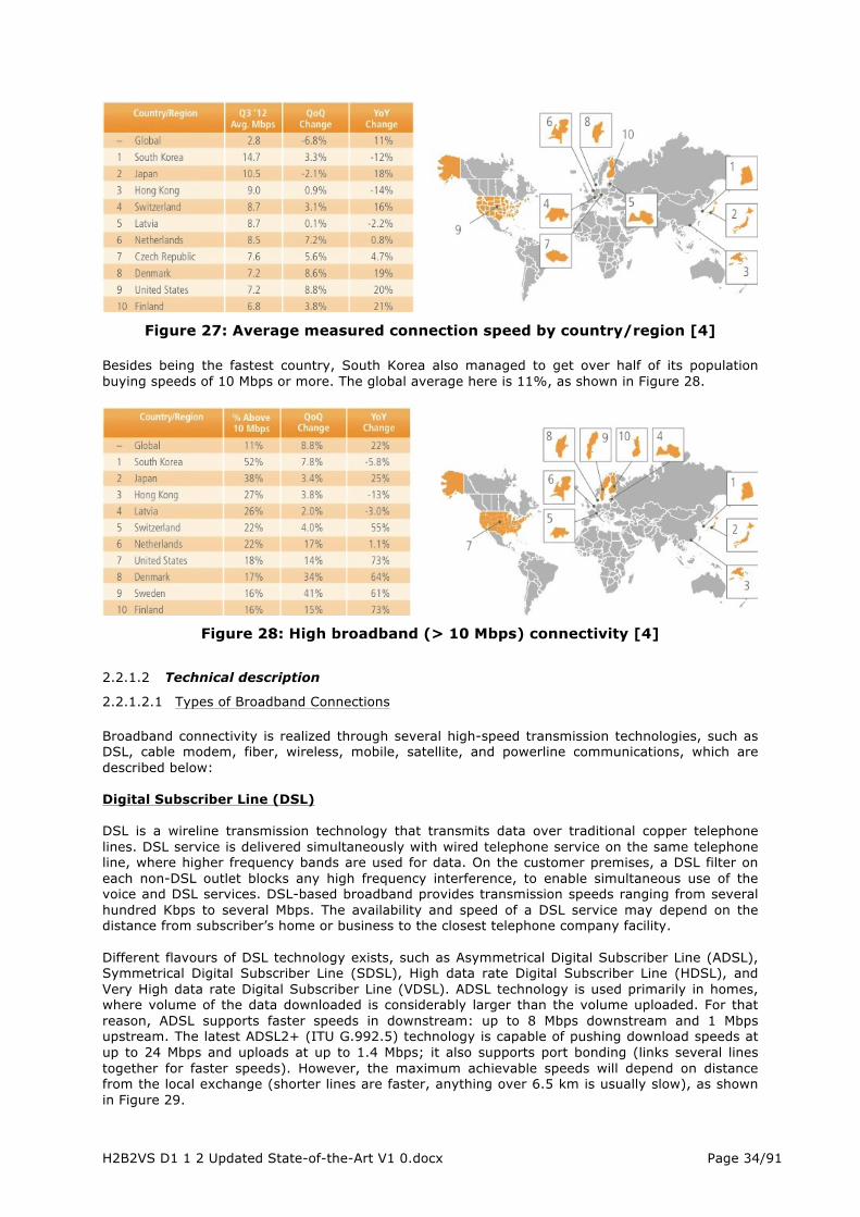
H2B2VS D1 1 2 Updated State-of-the-Art V1 0.docx Page 34/91
Figure 27: Average measured connection speed by country/region [4]
Besides being the fastest country, South Korea also managed to get over half of its population buying speeds of 10 Mbps or more. The global average here is 11%, as shown in Figure 28.
Figure 28: High broadband (> 10 Mbps) connectivity [4]
2.2.1.2 Technical description
2.2.1.2.1 Types of Broadband Connections Broadband connectivity is realized through several high-speed transmission technologies, such as DSL, cable modem, fiber, wireless, mobile, satellite, and powerline communications, which are described below: Digital Subscriber Line (DSL) DSL is a wireline transmission technology that transmits data over traditional copper telephone lines. DSL service is delivered simultaneously with wired telephone service on the same telephone line, where higher frequency bands are used for data. On the customer premises, a DSL filter on each non-DSL outlet blocks any high frequency interference, to enable simultaneous use of the voice and DSL services. DSL-based broadband provides transmission speeds ranging from several hundred Kbps to several Mbps. The availability and speed of a DSL service may depend on the distance from subscriber’s home or business to the closest telephone company facility. Different flavours of DSL technology exists, such as Asymmetrical Digital Subscriber Line (ADSL), Symmetrical Digital Subscriber Line (SDSL), High data rate Digital Subscriber Line (HDSL), and Very High data rate Digital Subscriber Line (VDSL). ADSL technology is used primarily in homes, where volume of the data downloaded is considerably larger than the volume uploaded. For that reason, ADSL supports faster speeds in downstream: up to 8 Mbps downstream and 1 Mbps upstream. The latest ADSL2+ (ITU G.992.5) technology is capable of pushing download speeds at up to 24 Mbps and uploads at up to 1.4 Mbps; it also supports port bonding (links several lines together for faster speeds). However, the maximum achievable speeds will depend on distance from the local exchange (shorter lines are faster, anything over 6.5 km is usually slow), as shown in Figure 29.
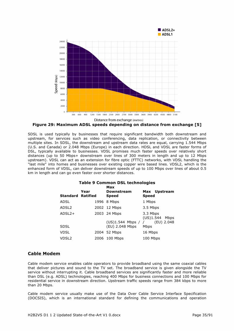
H2B2VS D1 1 2 Updated State-of-the-Art V1 0.docx Page 35/91
Figure 29: Maximum ADSL speeds depending on distance from exchange [5]
SDSL is used typically by businesses that require significant bandwidth both downstream and upstream, for services such as video conferencing, data replication, or connectivity between multiple sites. In SDSL, the downstream and upstream data rates are equal, carrying 1.544 Mbps (U.S. and Canada) or 2.048 Mbps (Europe) in each direction. HDSL and VDSL are faster forms of DSL, typically available to businesses. VDSL promises much faster speeds over relatively short distances (up to 50 Mbps+ downstream over lines of 300 meters in length and up to 12 Mbps upstream). VDSL can act as an extension for fibre optic (FTTC) networks, with VDSL handling the "last mile" into homes and businesses over existing copper wire based lines. VDSL2, which is the enhanced form of VDSL, can deliver downstream speeds of up to 100 Mbps over lines of about 0.5 km in length and can go even faster over shorter distances.
Table 9 Common DSL technologies
Standard Year Ratified
Max Downstream Speed
Max Upstream Speed
ADSL 1996 8 Mbps 1 Mbps ADSL2 2002 12 Mbps 3.5 Mbps
ADSL2+ 2003 24 Mbps 3.3 Mbps
SDSL
(US)1.544 Mbps / (EU) 2.048 Mbps
(US)1.544 Mbps / (EU) 2.048 Mbps
VDSL 2004 52 Mbps 16 Mbps
VDSL2 2006 100 Mbps 100 Mbps Cable Modem Cable modem service enables cable operators to provide broadband using the same coaxial cables that deliver pictures and sound to the TV set. The broadband service is given alongside the TV service without interrupting it. Cable broadband services are significantly faster and more reliable than DSL (e.g. ADSL) technologies, reaching 400 Mbps for business connections and 100 Mbps for residential service in downstream direction. Upstream traffic speeds range from 384 kbps to more than 20 Mbps. Cable modem service usually make use of the Data Over Cable Service Interface Specification (DOCSIS), which is an international standard for defining the communications and operation

H2B2VS D1 1 2 Updated State-of-the-Art V1 0.docx Page 36/91
support interface requirements of a data over cable system. DOCSIS3 is capable of reaching speeds of over 400 Mbps using 8 channel bonding. Fiber Fiber optic technology converts electrical signals carrying data to light and sends the light through transparent glass fibers about the diameter of a human hair. Fiber transmits data at speeds far exceeding current DSL or cable modem speeds. Depending on the configuration of the connection, various broadband fiber services exist, such as:
• Fiber To The Node (FTTN): Fiber is terminated in a street cabinet, possibly miles away from the customer premises, with the final connections being copper. FTTN is often an interim step toward full FTTH and is typically used to deliver advanced triple-play telecommunications services.
• Fiber To The Cabinet (FTTC): This is very similar to FTTN, but the street cabinet or pole is closer to the user's premises, typically within 300 meters, within range for high-bandwidth copper technologies such as wired ethernet or IEEE 1901 power line networking and wireless wi-fi technology. Service speeds of up to 80 Mbps download and 20 Mbps upload are possible with FTTC, while the actual performance will depend on the user’s distance to the street cabinet. Distance about 400 metres or less is required to get the best performance,
• Fiber To The Home/Premises (FTTH/P): Fiber reaches the boundary of the living space,
such as a box on the outside wall of a home. Passive optical networks and point-to-point ethernet are architectures that deliver triple-play services over FTTH networks directly from an operator's central office. Upload/download performance up to 1 Gbps is possible with this configuration, while consumer packages usually begin at 100 Mbps.
Wireless Wireless broadband connects a home or business to the Internet using a radio link between the customer’s location and the service provider’s facility. Wireless ISPs support broadband service typically in two different forms: Fixed Wide-Area Network or Hotspot. Fixed networks are stationary and designed to deliver Internet access over wide areas, while Hotspots are cheaper localised methods of Internet access that have been designed to cover smaller areas, such as restaurants or malls. Wi-Fi (IEEE 802.11) and WiMAX (IEEE 802.16) are the primary technologies used for wireless broadband connectivity. While both technologies can be used for the same purpose, Wi-Fi is usually used in home networks and Hotspots, whereas WiMAX has been specifically designed for wider area high-speed networking.
Table 10 Common wireless standards Standard Max Speed Frequency Wi-Fi 802.11a 2 Mbps 2.4 GHz or 5 GHz
Wi-Fi 802.11b 11 Mbps 2.4 GHz Wi-Fi 802.11g 54 Mbps 2.4 GHz
Wi-Fi 802.11n 100 Mbps to 600 Mbps 2.4 GHz or 5 GHz
WiMAX 802.16d 144 Mbps to 1 Gbps 2.3 GHz, 2.5 GHz, 2.6 GHz (UK) or 3.5 GHz
Mobile Broadband Mobile broadband is a wireless data communication technology that utilises cellular networks (e.g. 3G, LTE, LTE-A). The service is usually accessed through a mobile phone or a USB dongle connected to the PC. Mobile services are typically delivered over a wide range of radio frequency

H2B2VS D1 1 2 Updated State-of-the-Art V1 0.docx Page 37/91
spectrum bands (e.g. 900MHz, 1800MHz, 2.6GHz etc.), most of which can also reach indoors to a limited degree. As a basic rule, lower spectrum bands (e.g. 900MHz) can reach further outdoors and indoors than higher ones (e.g. 1800MHz).
Table 11 Common mobile access standards
Standard Max Downstream Speed Max Upstream Speed
GSM (2G) 14.4 Kbps 14.4 Kbps
GPRS (2.5G) 57.6 Kbps 28.8 Kbps EDGE (2.75G) 236.8 Kbps 236.8 Kbps
UMTS (3G) 384 Kbps 384 Kbps HSPA (3.5G) 13.98 Mbps 5.76 Mbps
HSPA+ (2x2 MIMO) 42 Mbps 11.5 Mbps LTE (4G) (2x2 MIMO) 173 Mbps 58 Mbps
LTE-A (4G) 1 Gbps 500 Mbps In order to help support the predicted rapid increase in multimedia traffic loads posed mobile broadband networks in the near future, 3GPP standards have included the Multimedia Broadcast Multicast Service (MBMS) from Rel-6 on. The extension enables resource efficient point-to-multipoint transmissions in mobile networks for live and on-demand content. Since its inclusion to LTE in Rel-9, the LTE broadcast service (also referred to as evolved MBMS or eMBMS) is seen mature enough to be really usable for operators. The basic operating principle of eMBMS is that the broadcast radio channels coexist in the same cell with unicast ones and share its resources. However, the radio resources can be allocated to the broadcast channels dynamically, that is, whenever and in the extent needed. eMBMS operates on a single-frequency network (SFN) technology, meaning that the content distribution can be directed to well-defined areas, ranging from a few cells serving a stadium to multiple cells covering an entire country. To terminals, the transmission seems to be originating from a single large cell over a time-dispersive channel. In terms of deployment, eMBMS requires extensions to the existing Evolved Packet Service (EPS) architecture. However, depending on the vendor, it can be enabled mainly with a software upgrade to the existing nodes. The use cases envisioned for eMBMS include naturally the delivery of live multimedia content but it can also be used for off-loading file transfers (e.g. software upgrades, delivery of popular content for caching at terminals, M2M connectivity and control). The MBMS user services are defined in 3GPP TS26.346. For live streaming, MPEG DASH can be used. Only instead of HTTP, DASH uses the FLUTE (File Delivery over Unidirectional Transport) protocol defined in IETF RFC3926 for the transport of segments over eMBMS. Additional reliability can be implemented with FEC. Using DASH partly helps the adoption of the eMBMS technology as the same player and live encoder head-end system can be used for both unicast and broadcast. Also, 3GPP is currently working towards enabling more flexible hybrid delivery modes for LTE and DASH [74]. These new standardization efforts are discussed briefly in Section 7.2.5. Satellite Just as satellites orbiting the earth provide necessary links for telephone and television service, they can also provide links for broadband. Satellite broadband is another form of wireless broadband, and is also useful for serving remote or sparsely populated areas. Downstream and upstream speeds for satellite broadband depend on several factors, including the provider and service package purchased, the consumer’s line of sight to the orbiting satellite, and the weather. Typically a consumer can expect to receive (download) at a speed of about 500 Kbps and send (upload) at a speed of about 80 Kbps. However, service can be disrupted in extreme weather conditions. Additionally, satellite is no good for fast paced multiplayer gaming either due to the time that it takes for signals to go from the Earth, to the satellite and then back again (high latency).

H2B2VS D1 1 2 Updated State-of-the-Art V1 0.docx Page 38/91
Powerline Communications (PLC) Powerline Communications (PLC) or Broadband over Power Line (BPL) is a little known technology that allows for the transmission of broadband Internet access to be conducted along existing national grid power cables, instead of the telephone network. It does this by separating out the electricity and internet service into two separate wavelengths. Unfortunately PLC technology is also notorious for producing high levels of interference (especially at higher frequencies) that can interrupt other services, such as the radio, and often resulted in serious conflicts with the national telecoms regulator. On top of that the cost of deployment and service delivery is also known to be high.
2.2.2 Content Delivery Networks The term “Content Delivery Networks” is commonly used for the delivery of many different types of content: media (audio/video), files, software updates, pictures, etc. The whole chapter is here mainly focusing on media content delivery (video/audio) as it is the general purpose of H2B2VS project.
2.2.2.1 Market Overview 2.2.2.1.1 Introduction A Content Delivery Network (CDN) is a system enabling optimization of the quality of content delivery over the Internet (or managed IP network). This is achieved by distributing servers deeper in the network to get closer to the end-users. When end-users ask for a media content, this is delivered from an edge server close to their location rather than from a centralized distant server. Since the first CDNs became commercially available in 1996 (Akamai, Limelight Networks), the market has been growing all over the years. Despite the progressive fall of CDN pricing due to strong competition, we observe an acceleration of global CDN revenues at worldwide level. This is mainly driven by the large volume increase of media content delivered over the Internet. The following figure is extracted from a market study produced in 2012 by Informa Telecoms & Media. It shows global revenues generated by commercial CDN service providers including both video and non-video services.
Figure 30: Foreground global revenues of CDN Service Providers (2010-2017)
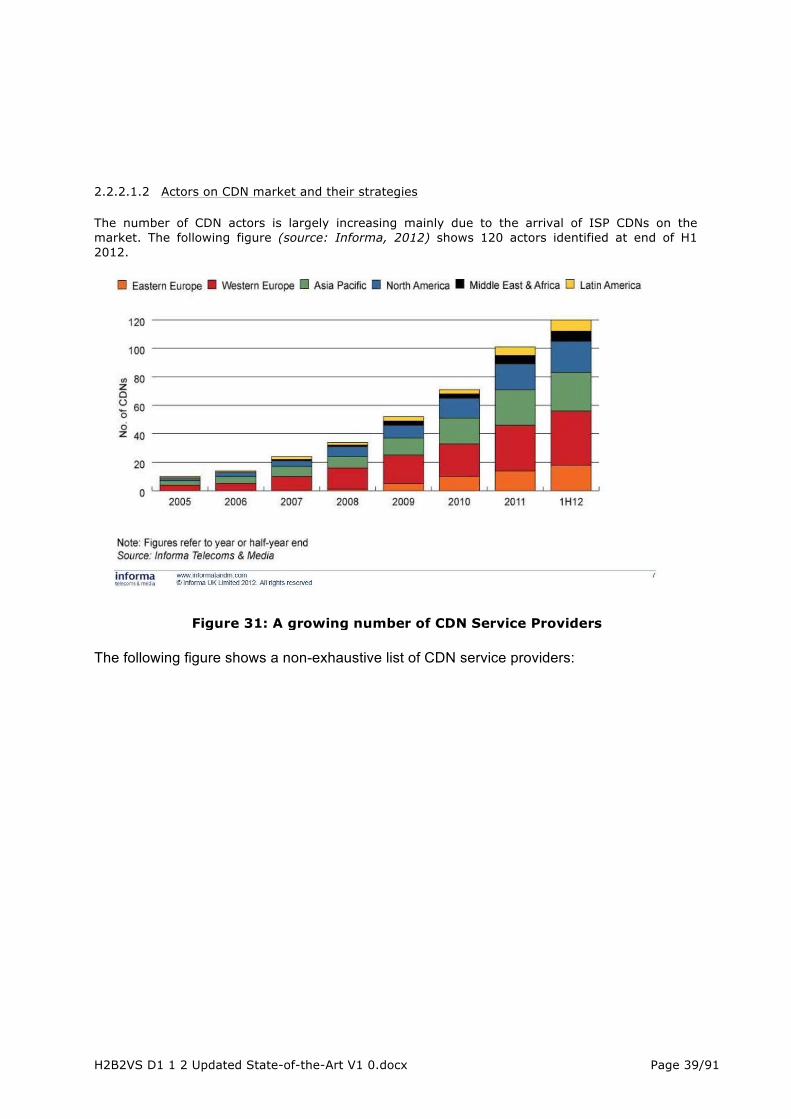
H2B2VS D1 1 2 Updated State-of-the-Art V1 0.docx Page 39/91
2.2.2.1.2 Actors on CDN market and their strategies The number of CDN actors is largely increasing mainly due to the arrival of ISP CDNs on the market. The following figure (source: Informa, 2012) shows 120 actors identified at end of H1 2012.
The following figure shows a non-exhaustive list of CDN service providers:
Figure 31: A growing number of CDN Service Providers

H2B2VS D1 1 2 Updated State-of-the-Art V1 0.docx Page 40/91
Figure 32: Examples of CDN Service Providers by category
On the market we can distinguish the following types of actors using CDN technology for the delivery of their own video services or selling it as a wholesale service:
- Large Content Service Providers: they need to deliver a very high amount of video traffic over the Internet and they tend to build their own dedicated CDN (e.g. Google with Google Global Cache, Netflix with their Open Connect, etc.). They need to buy connectivity (transit, paid peering) to network operators (telcos, ISPs) even if they also try to push their servers directly within the networks for free (promoting a cost reduction for network operators).
- CDN Pure Players: Content Delivery is their core business and they are providing wholesale CDN services. Most of them have a larger portfolio than pure CDN service (storage/origin, content preparation, Media Asset Management, Add Insertion, advanced analytics, security features, etc.). These actors can have different strategies regarding mainly:
o Targeted footprint: § Global and international actors: Akamai, Limelight Networks, Edgecast,
CDNetworks, Highwinds, Amazon CloudFront, OnApp (Cloud/software approach), etc.
§ Regional/local actors: SmartJog in Europe, NGENIX in Russia, ChinaCache in China, RSAWeb in South Africa, etc.
o Specialization: § Security features (e.g. CloudFlare) § Media: audio/video (e.g. SmartJog) § Acceleration services (e.g. Akamai/Cotendo, Yotta) § Etc.
These CDN pure players need to buy connectivity to network operators; with the objective (in particular for regional players) to put their delivery servers deeply in the network. In addition to their CDN service, several of them are recently trying to propose to ISPs licensed versions of their solutions (e.g. JetStream and Edgecast were the first to promote this way of collaboration).
- Telco and ISP CDNs: they use historically CDN for internal use (e.g. for their IPTV services) but also more and more to be able to sell a wholesale service (43 end 2012). On the contrary to previous types of actors, they own the network and they do not need to buy IP connectivity. Despite this, one of their main concerns is to be able to deliver content with high quality also outside of their legacy IP footprint and they try for example to promote CDN interconnection. The figure hereunder (source: Informa, 2012) shows different ISP/Telco’s strategies to enter the CDN game.
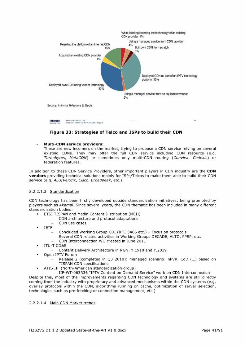
H2B2VS D1 1 2 Updated State-of-the-Art V1 0.docx Page 41/91
- Multi-CDN service providers: These are new incomers on the market, trying to propose a CDN service relying on several existing CDNs. They may offer the full CDN service including CDN resource (e.g. Turbobytes, MetaCDN) or sometimes only multi-CDN routing (Conviva, Cedexis) or federation features.
In addition to these CDN Service Providers, other important players in CDN industry are the CDN vendors providing technical solutions mainly for ISPs/Telcos to make them able to build their CDN service (e.g. ALU/Velocix, Cisco, Broadpeak, etc.)
2.2.2.1.3 Standardization CDN technology has been firstly developed outside standardization initiatives; being promoted by players such as Akamaï. Since several years, the CDN thematic has been included in many different standardization bodies:
§ ETSI TISPAN and Media Content Distribution (MCD) – CDN architecture and protocol adaptations – CDN use cases
§ IETF – Concluded Working Group CDI (RFC 3466 etc.) – Focus on protocols – Several CDN related activities in Working Groups DECADE, ALTO, PPSP, etc. – CDN Interconnection WG created in June 2011
§ ITU-T CD&S – Content Delivery Architecture in NGN, Y.1910 and Y.2019
§ Open IPTV Forum – Release 2 (completed in Q3 2010): managed scenario: nPVR, CoD (…) based on
TISPAN CDN specifications § ATIS IIF (North-American standardization group)
– IIF-WT-063R36 "IPTV Content on Demand Service” work on CDN Interconnexion Despite this, most of the improvements regarding CDN technology and systems are still directly coming from the industry with proprietary and advanced mechanisms within the CDN systems (e.g. overlay protocols within the CDN, algorithms running on cache, optimization of server selection, technologies such as pre-fetching or connection management, etc.) 2.2.2.1.4 Main CDN Market trends
Figure 33: Strategies of Telco and ISPs to build their CDN

H2B2VS D1 1 2 Updated State-of-the-Art V1 0.docx Page 42/91
Since a few years, CDN market has entered a little revolution due to ISPs willing to provide CDN services. This is still globally under building and the real impact of the market is hard to evaluate but there are already two important trends in the pipe:
- Partnerships between ISPs and CDN pure players in a managed or licensed mode (e.g. AT&T/Akamai, Edgecast/DT, etc.)
- CDN Interconnection In parallel, cloud actors are also moving towards CDN services. This is a natural move by adding an intelligence layer up to their existing storage/cloud infrastructures. Their main advantage is their ability to extend quickly their geographic presence. But their main drawback is that their infrastructure is not designed for CDN (no specific hardware) with potential quality issues:
- OVH in France - OnApp initiative to build a kind of CDN virtual market between its Cloud customers - Actors such as CDN77 building a CDN with a software approach
On the customer side, an important trend is their interest in moving to multi-CDN approaches. This provides them better redundancy/availability and the ability to have their content delivered with the most relevant CDN for each geographical area.
2.2.2.2 Technical description The main goal of a content delivery network is to handle the millions of simultaneous connections that can be requested on the websites pages, video and audio players. These connections have obviously to be served but also have to be served in the quickest way possible. To achieve these goals, CDNs need to develop intelligent solutions that will cache the content within different layers in their network to avoid overloading the source (called origin server). Then, this content is delivered by numerous edges servers located as close as possible to the end-user.
Figure 34: General architecture of a typical CDN

H2B2VS D1 1 2 Updated State-of-the-Art V1 0.docx Page 43/91
There are several technical orientations among CDN actors to deal with the complexity of providing the best quality of service and experience to the end user. The following quickly lists the issues and some of the orientations taken by the major actors. Maximise network speed: Some CDNs own a global network (Limelight, Level3) to limit the time needed to send the content from source to end-user. Some other CDNs use transit to communicate between POPS. In addition to this, CDNs can use either modified protocols or optimized routing protocols to deliver the content from the origin server to the edges. Maximise geographical proximity to the customer: For this, the best answer is to deploy as many POPs as possible all over the globe for a global player and POPs within a territory with local interconnection with ISPs for regional or domestic CDN. Maximise connectivity with end user: In addition to the number of POPs, connectivity with end-users is assured by ISPs. Dealing direct interconnections with local ISPs guarantee the best connectivity compared to peering or transit. Choosing the best transit operator when the CDN has no presence in the country is also a key point. Maximize caching efficiency: This is done through smartly managing TTL, having well designed caching strategy with several layers of hot and cold content, mixing localisation of the files in RAM and hard drive, etc. In addition to this, transparent caching can be applied to the content by ISPs (the ISP defines rules to cache content in their network without specific business agreement with the content provider, mainly for network cost reduction related to large traffic of websites such as YouTube). Handle millions of simultaneous streams: The capacity to handle millions of simultaneous users can be achieved by optimizing the cache software and system, having massive deployment of hardware, using virtualization to be able to increase in the size of the streaming farm. In addition to this, the CDN needs to have a huge network capacity with ISPs, peers and transit operators. It can also be done through the use of multicasting, especially in enterprise business where network can be managed or for ISPs which control their boxes. This dimensioning issue is particularly important for media content delivery, as the traffic curve includes regularly high peaks of content consumption (e.g. news events such as for example major sport events, Bin Laden’s death or Obama’s election, etc.). Direct the user to the best streamer and even CDN in case of multi CDN This can be done using several techniques such as using DNS based routing, HTTP redirection, hardware or software load balancers, on the player side based on QoE measurement, etc. In addition to providing the best path to deliver the content to millions of users, there is more complexity when dealing with the expected functionalities. Provide content to all connected devices with a large set of OS and players The increasing complexity comes from the very fragmented device market. There are many types of devices, OS, players, size of screen leading to the need to support multiple protocols for a single asset. The main protocols are currently HLS, MSS, HDS, WMS RTMP, RTSP, TS over HTTP (HBBTV 1.1), Icecast and Shoutcast for radio. Some are old and disappearing (connected protocols) and the tendency is to move towards HTTP based adaptive streaming. And more are coming such as MPEG-DASH as the unique standardized adaptive streaming protocol. This leads some CDNs to implement the “unique URL feature” which is a layer able to detect which device is requesting a stream and deliver the content with the relevant protocol. Protect the customer’s content Rights holders are still very reluctant to provide their content without any protection. CDNs provide different levels of protection to their customers. It can start from token based URL (the URL can be used only for a limited time to avoid cross referencing on other websites), georestriction (limit to certain territories), referrer (limit access to a player located on a given domain name), HTTPS (hide the content of a playlist for instance), simple encryption between server and player (RTMPE, HLS+AES encryption, specific protocols needing to implement a SDK in the players), up to DRM which is provided by some CDNs as additional service but is not in the pure scope of a CDN.

H2B2VS D1 1 2 Updated State-of-the-Art V1 0.docx Page 44/91
Provide real-time analytics and QoE measurement There are two types of analytics: server side and player side. The first one provides the vision of the CDN. The second one provides the vision of the user (QoE) but needs to be implemented in players. The biggest complexity is that both are generating billions of logs per day which need to be treated in real time and can be used by the CDN to take routing decision, changes in the bit rate, detect issues on streamers, etc. When using player side analytics, it can be used to route the traffic from a CDN to another with better performance while continuing playing the content. The use of Big Data and cubes technologies are becoming more and more important to handle such level of data management. The CDN market is in perpetual movement with new formats coming every day (new protocol (DASH), new access network technologies (4G), new DRM (Widevine, HTML5), new codecs (HEVC), new formats (4K, 8K), etc. Even though not all these changes are directly CDN related (such as Codec), they may potentially impact CDN systems that need to take them into account. The challenge of CDN industry is to finally agree on a common protocol supported by all the major platforms (iOS, Androïd, connected TV, HBBTV, Windows, MAC, Linux…). DASH seems to be the best candidate but some of the major platforms are reluctant to make the move. In addition to this protocol format issue, one of the main challenges will be to tackle the huge growth of traffic forecasted for the next years. It requires important investments while in the meantime prices are dropping.

H2B2VS D1 1 2 Updated State-of-the-Art V1 0.docx Page 45/91
3 COMPRESSION 3.1 HEVC standard The transmission of next-generation video requires coding efficiency that is beyond the capabilities of the well-known H.264/MPEG-4 AVC standard. Therefore, ITU-T Video Coding Experts Group (VCEG) and ISO/IEC Moving Picture Experts Group (MPEG) established a Joint Collaborative Team on Video Coding (JCT-VC) in 2010 to develop a successor to AVC. This new international standard was named as HEVC (High Efficiency Video Coding) [15]. HEVC obtained Final Draft International Standard status in the MPEG standardization in January 2013 and it was approved as an ITU-T standard (HEVC/H.265) in April 2013. The JCT-VC team then worked on HEVC extensions to cover several supplementary application scenarios such as 3D/stereo/multiview video coding, scalable video coding, and professional uses with enhanced precision/color format. A second version of HEVC standard which includes all these extensions was approved in October 2014. The main goal of HEVC is to improve the compression efficiency by two over AVC with the same perceptual video quality. The evaluation results show that this objective has been met. HEVC is reported to reduce bit rate close to 40% with an equivalent objective quality and its bit rate savings rise up to 50% when subjective visual quality is used as a quality measure [9] [16]. The benefits of HEVC are shown to emphasize with low bit-rate, high-resolution, and low-delay applications. The other objectives of HEVC include ease of transport system integration, data loss resilience, and increased use of parallel processing architectures. HEVC streams are identified with a profile and a level, as in the previous standards: the profile specifies the tools which shall be supported by the decoder, while the level specifies the constraints on the processing and memory capacities. These constraints are typically the maximum number of blocks per second and the maximum bitrate. HEVC standard added the tier notion to specify different maximum bitrates constraints for a given level. HEVC adopts a conventional hybrid video coding scheme (inter/intra prediction, transform coding, and entropy coding) used in the prior video coding standards since H.261. As a new feature, its coding structure has been extended from a traditional macroblock (MB) concept to an analogous block partitioning scheme that supports block sizes up to 64 × 64 pixels. The block sizes can be content-adaptively adjusted between large homogeneous regions and highly textured regions of the picture. This new coding structure is the primary factor for HEVC coding gain which is further enhanced by new or modified coding tools of inter/intra prediction, transform, entropy coding, and filtering. Table 12 compares the tool sets of HEVC with those of AVC and MPEG-2 in more detail. HEVC has gained a strong interest among industrial and academic bodies. Currently, almost all essential players are more or less involved in HEVC standardization. In addition, the future trend is that the processing performance will continue to develop faster than transmission and storage technologies. This trend will further promote HEVC because of its capability to halve the bit rate. Due to these reasons, HEVC is also adopted by H2B2VS.

H2B2VS D1 1 2 Updated State-of-the-Art V1 0.docx Page 46/91
Table 12 Toolset differences between HEVC, AVC, and MPEG-2 [6]
3.2 HEVC encoding The three profiles (Main, Main10, Main Still picture) defined in the first version of the standard were all dedicated to consumer applications with 4:2:0 video contents and are therefore perfectly adapted to the framework of H2B2VS project. The Main Profile supports a bit depth of 8 bits per colour, which is the most common bit depth in consumer devices. The Main Still Picture profile allows for a single still picture to be encoded with the same constraints as the Main profile. The Main 10 profile has been adopted in the first version of the standard thanks to the initiative of a few broadcasters, such as DirecTV, BBC, BSkyB, NHK, SVT and manufacturers such as Technicolor and Thomson Video Networks [7]. This initiative aims at giving the choice to broadcasters to offer a better user experience for Ultra-HD format with 10-bits depth associated to a wider color gamut and avoiding any “legacy” issue if HEVC had been deployed with a single 8-bits depth profile. From the beginning, the goals of HEVC standard were to achieve significant compression efficiency over H.264/MPEG-4 AVC to address increased video resolution and to favour:
- a wide use of High definition on any kind of devices, - the emergence of Ultra-HD formats (3840x2160 resolution, commonly named as 4K and
7680x4320 resolution, commonly named as 8K), - the development of multi-view systems.
Among the 13 levels defined in the standard, the first 9 ones can be considered by H2B2VS applications and the following ones are of particular interest:
- Level 4.0 : HD 1080p25,
- Level 4.1 : HD 1080p50,

H2B2VS D1 1 2 Updated State-of-the-Art V1 0.docx Page 47/91
- Level 5.0 : Ultra HD (4kx2k) p25
- Level 5.1 : Ultra HD (4kx2k) p50
Both objective (PSNR-based) and subjective quality assessments have been performed within the JCT-VC and test results confirm that the initial goal can be reached:
• In Main profile, HEVC can provide a bit rate savings of 40% for equal PSNR on the 1080p sequences and 45% on Ultra HD sequences,
• The bit rate savings when considering equal subjective quality is even greater, more than 50% for all the test sequences and up to 70% for two of them.
A good overview of compression performance (objective and subjective assessments) as well as computation time is given in [8]-[14].
The modified coding structure of HEVC is the primary factor for its coding gain. Accommodating the coding tools to this new coding structure creates the major computational overhead. Table 13 tabulates the average shares of the most complex stages of HEVC encoding under the all-intra (AI), random access (RA), low-delay B (LB), and low-delay P (LP) coding configurations. Random access configuration will be typically used for broadcast applications. These results are obtained by profiling Main Profile (MP) of HM 6.0 with Intel Vtune [9].
Table 13 Average Shares of the Most Complex Encoding Stages of HM MP [9]
The stages of inter prediction (IME and FME) are the most complex ones due to their numerous prediction modes and block partitions that have to be evaluated during the rate-distortion optimization. However, computation of HEVC is still very well mastered, since the overall encoding complexity is increased only by 20% over AVC reference encoder JM HiP (High Profile) when all essential coding tools of HM MP and JM HiP are used in random access case. Table 14 reports the rate-distortion-complexity (RDC) differences between HM MP and JM HiP in AI, RA, LB, and LP cases.
Table 14 RDC Summary of HEVC MP (HM 6.0) AND AVC HIP (JM 18.0) [9]
Though, the complexity overhead estimation of HEVC encoding over AVC based on SW reference models of these two compression standards cannot be considered as a rigorous way to measure encoding complexity overhead, because: On one side, the two SW models are not written with the same language (C++ for HEVC, C for AVC) to the advantage of AVC, On the other side, it is well known that AVC SW model is not written to get a good computation performance. Estimations derived from on-going real-time implementations on Intel-based PC servers give a ratio around 3 on a HD format compared to H.264/AVC. This extra overhead, even if bigger than the one given with SW reference models, is much lower than the one, which was existing from MPEG-2 to H.264/AVC (ratio around 10). Moreover, the HEVC standard is well adapted to parallel processing and can make the best use of the new generation of multi-cores processors. This parallel processing can be extended up to the entropy coding thanks to Wavefront Parallel Processing (WPP) without compression performance degradation. This well-mastered complexity overhead is good news to allow real-time coding of bigger video formats (bigger picture resolution, higher dynamic ranges and/or frame rates) in the next few years.

H2B2VS D1 1 2 Updated State-of-the-Art V1 0.docx Page 48/91
Real-time software encoders for full HD (1080p@30fps) have already been announced by many companies including Ateme, Elemental Technologies, Fraunhofer HHI, MainConcept, Thomson Video Networks, and Vanguard Video. Some of these software solutions are able to support 10-bit live HEVC encoding up to 2160p@60fps format. Besides these proprietary implementations, there also exist three noteworthy open-source HEVC encoders: f265 [74], Kvazaar [75], and x265 [76]. In addition, a couple of hardware HEVC encoders can already be found in the market. For example, Ambarella, NGCodec, and ViXS Systems have released their HEVC encoders on a System-on-Chip (SoC). Up to this date, the highest known HEVC encoding performance is obtained by NHK and Mitsubishi Electric that have jointly developed a real-time hardware HEVC encoder for 10-bit 8K (4320p@60fps) video [77]. First Ultra-HD 4K consumer displays are now available with prices which are significantly dropping, but frame rate is limited to 25/30 frames/s, which can be considered acceptable for Video-on-demand applications using movie content but is considered as too low by a large majority of video experts for live video content, especially sport content. A few research centers, like NHK or BBC, even argue that framerate of 100 to 120 frames/s is necessary to eliminate flicker and to keep stroboscopic effect. This Ultra-High frame rate does not seem to be a short term target for broadcast services and should not appear before 2020. Therefore, H2B2VS project will be focused on 50 fps framerate for Ultra HD 4K live services.
10-bits depth seems to be the appropriate answer for Ultra HD format using a wider colour gamut (BT.2020), in order to avoid banding effects. A wider luminance dynamic, brought in High Dynamic Range (HDR) systems, would allow a perfect restitution of details even in the lightest or darkest zones of pictures, which is closer to the human perception of its environment. Though, even if some cooperation programs, like French national project Nevex, have been launched to promote HDR solutions support within HEVC standard, this is not yet considered in HEVC range extensions under study (limitation to 14 bits depth). It seems that it will take time before Ultra HD 4K displays with HDR technology reach mass market prices. The second version of HEVC standard brought scalable extensions of HEVC (SHVC). SHVC supports spatial, SNR, bit depth and color gamut scalability, in addition to temporal scalability which was already included in HEVC Version 1. Scalable extensions have been conceived with only high-level syntax changes to ease backward compatibility with HEVC:
- Upper layers can use reference frames from the base layer frames after appropriate up-sampling,
- Prediction of the upper layers can use the motion vectors of the base layer after appropriate remapping.
Scalability layer is identified with a layer_id in the header of NAL Access Units to ease packets routing in the networks. High level syntax (Video Parameter Set) defines operating points with the list of layers, which are necessary to build it.
Figure 35 – Layers in a SHVC stream
Two profiles are defined: Scalable Main and Scalable Main 10. When the layer conforms to the Scalable Main/Main 10 profile, the base layer sub-bitstream baseBitstream conforms to the Main/Main 10 profile, respectively. Possible levels for the layers are the ones defined in HEVC Version 1. It must be noted that SHVC supports an AVC base layer.
Legend:
SHVC non-base layer, LayerId = 3 SHVC non-base layer, LayerId=3
SHVC non-base layer, LayerId=2
HEVC sub-partitions
HEVC base layer, LayerId = 0
HEVC base sub-partition
720p
1080pSHVC non-base layer, LayerId=1
2160p
2
1
3
54
i Operation Point i
TemporalId = 0 (60 fps) TemporalId = 1 (120 fps)TemporalId = 0 (30 fps)
H2B2VS D1 1 2 Updated State-of-the-Art V1 0.docx Page 49/91
H2B2VS project had a close look on this activity since simple scalable solutions could emerge and could be the right answer for the transport of an AVC or HEVC-based HD 1080p base layer on the broadcast network and a HEVC Ultra HD 4K enhancement layer on the broadband network. Our tests in a broadcast configuration (Random Access configuration) show that HD to UHD spatial scalability can bring an average of 20% gain over simulcast for the same quality. The UHD scalable stream still brings an over-cost compared to the simple UHD stream (around 10%) but the scalable scheme can be considered as an interesting scenario for the introduction of UltraHD on top of existing HD services. On the 3D topic, different tracks are under investigation within MPEG: extension of MVC with depth map support, combined video/depth 3D AVC, MVC-like extension of HEVC (MHVC), combined video/depth 3D HEVC. The MVC-like extension of HEVC (MHVC) is included in Version 2 of the HEVC standard. A stereo HEVC MVC solution could be considered on a hybrid broadcast-broadband transport system.
3.3 HEVC decoding The new video compression standard HEVC [15] improves the compression efficiency by almost a factor of two (40%) compared to the H.264/AVC standard. In addition to this gain in terms of rate-distortion performance, the HEVC decoder decodes videos with a high subjective quality [16]: HEVC performs the same subjective quality than H.264/AVC with half bit-rate. The high compression performance of the HEVC standard is allowed by new compression tools used in the standard such as the in-loop Simple Adaptive Offset (SAO) filter, large prediction and transform blocks as well as the Context Adaptive Binary Arithmetic Coding (CABAC) [15]. This good coding performance makes the HEVC standard attractive for several new applications and services, such as High Definition Digital Television (HDDT), Very High Resolution HD video conferencing and Hybrid Broadcast Broadband Television. ; some of these scenarios will be part of the H2B2VS project. The main objectives in designing the HEVC decoder are the following:
1) Implement a HEVC decoder that supports the decoding of all profiles and levels defined in the standard as well as all possible coding configurations.
2) Low complexity decoder: design HEVC decoder architecture that performs fast decoding process, while using minimum memory and CPU resources.
It should be noted that the current draft of the standard does not mandate any rule concerning the implementation of the decoder. However, the HEVC standard was designed with a particular attention to reduce the complexity in order to perform real time encoding/decoding process with both software and hardware implementations. In fact, the implementation cost of the HEVC decoder is not much higher than the one of H.264/AVC, even with additional tools, such as the SAO filter [17]. There are several solutions that leverage the Multi-core processors to parallelize the decoding process and archive a real time decoding of very high resolution video sequences (HD, 4K and 8K4. The HEVC standard defines three concepts allowing performing a high level parallelism1 of the decoding process namely slices tiles and wavefronts. Slices and tiles break the prediction dependencies at their boundaries allowing decoding of each slice or tile simultaneously on a separate core. The in-loop filters are performed on the slices and tiles boundaries once these tiles and slices are decoded. In addition that the later step cannot be parallelized tiles and slices concepts decrease the rate-distortion coding efficiency caused by: perdition limitation, extra headers and resynchronisation of the arithmetic encoder. A new concept called slice entropy was introduced in the HEVC standard. Slices entropy is similar to slices, except that slice entropy concept allows prediction over slice borders and reduces the size of the slice header. Thus, only the CABAC context is synchronized at the beginning of the slice entropy. The Wavefront Parallel Processing (WPP) concept was proposed to the HEVC standard in [18]. Wavefront concept splits the picture into Coding Tree Block (CTB) rows, where dependency between CTB rows is maintained, except the context of the arithmetic encoder which is initialized at the start of each CTB row. To limit the overhead caused by initialising the context state of the CABAC, this one is initialized from the second CTB on the previous CTB row. In [19] the authors 1 Simultaneously decode/encode different spatial regions of a single picture.
H2B2VS D1 1 2 Updated State-of-the-Art V1 0.docx Page 50/91
proposed parallel HEVC video decoding solution that combines the concepts of wavefront and slice entropy. Results show that the proposed solution allows a speed up of factor 3 by using four threads and a speedup between 5 and 6 (depending on the picture size) by using 12 threads. On the other hand, there are several HEVC decoding steps that can be performed in parallel processing in the HEVC standard. First, the CABAC decoder can support parallel context processing, where the decoder derives several context indices in parallel. The HEVC explicitly signals the horizontal and vertical offset of the last significant coefficient before parsing the significant coefficient flag [20]. This modification allows faster parsing of the transform coefficient coding, especially at high bit-rates by avoiding arithmetic decoding bottleneck. In the HEVC standard, parallel optimization can also carried out at the level of the in loop filters. The deblocking filter and the SAO filter can easily performed in parallel processing. The authors in [21] put in competition three methods to parallelize the deblocking filter in the HM software. The first method parallelizes the vertical edge filtering and the horizontal edge filtering in separate passes, while the other two methods manage the vertical edge filtering and the horizontal edge filtering in a single pass. Simulation results shows that the three methods archive an accelerating factor (speedup) near to the number of threads handling concurrently the filtering [21]. All these optimizations allow reaching real time decoding of a high resolution video quality (HD and 4K2K) with the HEVC decoder. In addition to the HM implementation, several companies (ATEME, ETRI, NTT DOCOMO, Inc. & DOCOMO Innovations, Inc., Mitsubishi Electric Corporation and NHK) and academic (IETR) partners implemented their own HEVC decoder. ETRI showed, in the JCT-VC meeting (01/2013), a hardware implementation of the HEVC decoder [22]. This solution is capable of decoding 1080p HEVC bit-stream (based HM-6.0) at 60 fps, which shows the feasibility of the HEVC decoder. Hardware implementation of HEVC encoder was proposed in the JCT-VC meeting by Mitsubishi Electric Corporation and NHK. This solution is FPGA-based prototype which supports a real time encoding of 1080p video sequence at 60 fps with Main 10 HEVC profile [23]. The multi-threading implementation of the NTT DOCOMO is capable to decode in real time 4K2K video sequences at 60 frames per second (fps) on a laptop with a quad-core Core-i7 processor [24]. The real time decoding is reached by using 3 threads using CRA-based GOP-level parallelism, which is not very efficient in terms of memory allocation. The IETR laboratory developed in the project 4EVER an open source HEVC decoder called OpenHEVC [25]. This implementation supports several profiles specified by the HEVC standard and performs a good performance in terms of frame rate decoding. It reaches a near real time decoding performance for high quality HD size video without any parallel processing. Therefore, adopting, in this implementation, one of the parallel solutions described above (wavefront or slice entropy) allows reaching real time decoding for HD and even 4K2K videos on multi-core processors. Table 15 shows the performance in terms of decoding frame rate of the OpenHEVC decoder for several video sequences and coding configurations. Without any parallel processing, this implementation allows real time decoding performance for 720p videos in all coding configurations. For HD video sequences, the real time decoding is archived in Main Low delay and Main Random Access configurations and quantization parameter of 27, which results in good decoded video quality.
Table 15 Decoding time performance of the open source HEVC decoder OpenHEVC (based HM-10)
Video sequences QP Resolution Frame Rate (fps) Main Intra Main Low delay Main Random
Access Jony (60 fps)
27 1280x720
48 139 130
KristenAndSara (60fps) 43 110 108 Cactus (50 fps) 1920x1080
(HD) 14 31 33
Kimono1 (24 fps) 18 23 25 Jony (60 fps)
22 1280x720
38 101 100
KristenAndSara (60fps) 36 83 86 Cactus (50 fps) 1920x1080
(HD) 10 18 20
Kimono1(24 fps) 14 17 20

H2B2VS D1 1 2 Updated State-of-the-Art V1 0.docx Page 51/91
The scalable extension of the HEVC standard, called Scalable High Video Coding (SHVC), is under work in the Joint Collaborative Team on Video Coding (JCT-VC). One of the objectives of the IETR laboratory, in H2B2VS project, is to extend the OpenHEVC implementation to also support the decoding of SHVC bit-stream. Therefore, OpenHEVC implementation will support both HEVC decoding when the bit-stream contains only the base layer quality (HEVC), and the decoding of both base layer and enhancement layer for SHVC compliant bit-stream.

H2B2VS D1 1 2 Updated State-of-the-Art V1 0.docx Page 52/91
4 TRANSPORT LAYER
4.1 Adaptive HTTP Streaming This section introduces the evolution of video streaming over IP and adaptive HTTP streaming. The section focuses especially on the Dynamic Adaptive Streaming over HTTP (DASH) standard and its features and potential.
4.1.1 Introduction
4.1.1.1 Evolution of audio/video Streaming over IP Delivering video and audio over IP started in the 90’s with use of UDP/RTP protocols defining formats for encapsulating the media and session protocols (RTPS, RTMP) for managing the playing sessions. For IPTV operators, that use Managed Networks with controlled delay and reduced error rate, it is common to use RTP/UDP multicast to encapsulate live channels into network packets and broadcast them to the final users. For VoD contents the use of video servers with RTP/UDP unicast streaming for the media with a RTSP control session was also very common. In this solution, that is called Streaming, the servers in the head-end send media packets timely to the clients that are consuming the emitted data in real time. The main characteristics of streaming are:
• Content (Live channel, VoD content) is delivered at encoding rate • Consumption is on the fly with very little buffering in the decoder and very low end to end
delay can be achieved. • Allows Trick modes (PLAY, REW, FF, STOP, JUMP) with very low delay • Best BW utilization due to the used protocols with low overhead
This streaming solution has been valid for IPTV operators up to now when they want also to offer services OTT (Over-The-Top) when they need to use Internet for distributing these services. For Internet the situation is different than in Managed Networks:
• Multicast addresses are not allowed so it is not possible to broadcast live channels, they must be sent as unicast channels that must be streamed to every client.
• RTP & RTSP are used for both Live and VoD Content and a server must maintain a dedicated streaming connection with every client, acting as a video server and maintaining a state for every connection, requiring too much power in these servers that gives low scalability.
• These protocols do not travel easily through Internet like most routers, firewalls, etc. does not allow them by default and they need to be activated manually.
• Internet cannot guarantee the end-to-end delay, the bandwidth and the error rate, so depending on the Network conditions the quality of the service can vary from good to very bad.
With the growing of the World Wide Web using HTTP protocol and the improvement in bandwidth in the Internet network, the solutions for streaming were also using HTTP for sending video/audio packets. This is HTTP Streaming and its main features are:
• HTTP travels easily in the network as all infrastructures are configured to pass this type of services and the connections are possible around the world.
• HTTP uses TCP that offers error free connections using retransmissions, so no caution is needed about errors in the network
• The media files are stored in a conventional Web Server, a specific video server is no longer needed, and the clients ask for media using the HTTP GET command.
• Web servers can serve a large number of clients with low cost and it is not needed to maintain a session for every client so scalability is achieved.
• The CDN (Content Distribution Network) infrastructure used for Internet contents can also be used for media contents, as they are files that can be stored in the CDN caches so the huge traffic is maintained between the local caches and the final clients and the long-haul traffic is reduced.
For these reasons HTTP streaming has been very successful and is currently the preferred streaming method in Internet.

H2B2VS D1 1 2 Updated State-of-the-Art V1 0.docx Page 53/91
There are several modalities of HTTP streaming:
• Firstly the File downloading or File streaming where the complete media file is retrieved from the server to the client and then the reproduction is started.
• As an improvement follows the Progressive Downloading where only a part of the file is buffered in the client for a relative short time and then the PLAY is started.
Nevertheless HTTP streaming maintains some drawbacks:
• Internet does not guarantee a constant bandwidth as it is very dependent on the use of the network in every moment, so some content encoding at a certain bit rate can run fine at some moments and not at others.
• In HTTP some buffering is needed in the client (decoder) to guarantee that this does not empty and the reproduction stalls. This buffering adds delay that is especially important in live contents.
• HTTP uses TCP that correct errors but introduces delay, due to retransmissions, that must be absorbed also in the decoder buffer.
• Even with enough buffering the reproduction can stall in some situations. The conclusion is that HTTP streaming does not offer the required level of Quality (QoS and QoE) that is expected by TV providers and final users. To solve these issues the last step in this evolution has been the HTTP Adaptive Streaming (HAS) that, while being based in HTTP streaming, ads the following elements:
• Every audio/video content is encoded, for live or VoD, at different qualities (different bitrates) generating different streams so it is possible for the decoder to use one or another depending on the bandwidth offered by the network in every moment.
• Every stream is fragmented in chunks or segments of a certain duration, i.e. 2 up to 10 Sec, that are aligned across all the qualities so it is possible for the client to switch from one segment in one quality to the next segment in other quality without video and audio interruption (seamless switching).
• All segments are stored as files in the Web server and the client can retrieve them with HTTP.
• In the Web server it is necessary to generate a special description file, called the ’Manifest’, which, for every content, describes the channel in terms of bitrates, segments properties and URL’s needed to access all the segments.
• When a client wants to reproduce a channel that is defined by the URL of the Manifest, it retrieves the Manifest, parses it to obtain the number of available qualities in that channel and the URLs to access the segments. The client measures the available bandwidth in the network (or other factors) and asks for segments of the appropriate quality to get an uninterrupted reproduction. If the network conditions change the client can change in real time from one quality to another maintaining a continuous reproduction of the content.
With HAS a much better quality can be obtained than with the conventional HTTP streaming. There are in the market several implementations that are proprietary and incompatible between them:
• HTTP Live Streaming (HLS) by Apple
• Smooth Streaming (HSS) by Microsoft
• HTTP Dynamic Streaming (HDS) by Adobe They use different Manifest formats and different formats for the segments, so specific clients are required and are not interoperable.
4.1.1.2 Example of Adaptive Stream session Figure 36 shows a very simple example of an HTTP Adaptive Streaming and the HTTP requests that are made by the client.

H2B2VS D1 1 2 Updated State-of-the-Art V1 0.docx Page 54/91
Figure 36: HTTP Adaptive Streaming example
The Web server stores the Manifest that describes the qualities and the fragments of the content. The video content is encoded in different bitrates, e.g. 4, 2 and 0.5 Mb/s, and is fragmented in e.g. 10 Sec chunks. All the chunks are aligned in time and all begin with an IDR frame, so it is possible to change between one quality stream to another seamlessly. The client retrieves by an HTTP GET (1) the Manifest file and obtains the number of qualities of the video and audio and other properties of the media such as resolutions, codecs, etc., and also obtains information about the segment duration and its URL. The client strategies could be very diverse but, for example, the client gets the first segment of the highest bitrate (2) and with them it estimates the bandwidth available in the network. If the bandwidth is not sufficient enough it can move to other quality and requests for the most appropriate bitrate (3). The player can start the PLAY when its buffer has reached the correct value and from this point and going on the client calculates the available network bandwidth and switches to one or other quality depending on that. There are other factors that the client can use to select the quality that will be reproduced, i.e. the resolution of the content to match that of the display, the audio/video codec supported by the client, the CPU usage of the client, etc.
4.1.1.3 Standards The lack of standards in HTTP Adaptive Streaming means that it is not possible to build HAS clients that can connect and play correctly contents from servers from different manufacturers and this is an important impediment for the wide deployment and growing of the Adaptive Streaming. Several attempts for standards have been made:
• 3GPP: mobile world moving towards HAS o Release 9 included the first HTTP adaptive streaming spec, based on fragmented
MP4 o Published in 2010, strongly influenced OIPF and DASH
• OIPF: incorporating the fixed devices
o Based on 3GPP spec, adds MPEG2-TS format (popular in fixed devices) o Included in Release 2 (2010). No market footprint beyond reference
implementations
4.1.2 MPEG-DASH The objective of MPEG-DASH (MPEG-Dynamic Adaptive Streaming over HTTP) is to create an international standard that allows HTTP streaming in an interoperable way between a great variety of servers and clients (TVs, STBs, PC’s, game consoles, tablets, mobiles phones, etc.). To achieve this objective and observing the market prospects of Internet Streaming and by the request of the industry, MPEG issued a Call for Proposal for an HTTP streaming standard in April 2009. Fifteen full proposals were received by July 2009, when MPEG started the evaluation of the

H2B2VS D1 1 2 Updated State-of-the-Art V1 0.docx Page 55/91
submitted technologies. In the two years that followed, MPEG developed the specification with participation from many experts and with collaboration from other standard groups, such as the Third Generation Partnership Project (3GPP). The resulting standard is known as MPEG Dynamic Adaptive Streaming over HTTP (MPEG-DASH) and has been published as ISO/IEC 23009-1 [26]. As a fundamental feature, DASH proposes an automatic switching of quality levels according to network conditions, user requirements, and expectations. Part 1 of the DASH standard (ISO/IEC 23009-1) specifies how to structure a Multimedia Presentation Description (MPD) and its representation in terms of segments. DASH aims at enabling content adaptation in existing HTTP client-server systems, while maintaining the benefits of traditional HTTP streaming, i.e., reuse of existing Internet infrastructure comprising caches, CDNs, and traversal of NATs and firewalls. It is worth highlighting that the standard is intended to support a multimedia streaming process that is deliberately controlled by the client. This enables existing HTTP server to support DASH without any extensions or modifications whatsoever. In parallel with DASH other companion specifications has been specified:
• ISO/IEC 14496-12/AMD 3: extension to ISO base media FF to support DASH • ISO/IEC 23001-7: Common Encryption (CENC)
The next subsections will introduce DASH in detail.
4.1.2.1 Scope of DASH As defined in the standard: ‘Dynamic Adaptive Streaming over HTTP (DASH) specifies XML and binary formats that enable delivery of media content from standard HTTP servers to HTTP clients and enable caching of content by standard HTTP caches’. The scope is defined in Figure 37 where only the formats and functionalities in orange blocks are defined by the specification.
Source: Qualcomm Incorporated
Figure 37: DASH Scope That is, DASH standard only specifies:
• Manifest syntax: It is an XML document called MPD. • Segment URL building: How to access segments. • Segments properties • Content protection framework
DASH standard does not specify:
• MPD delivery (can be HTTP or others) • Media multiplex formats (MPEG2-TS, ISO-FF, any other) • Audio and Video and other codecs.
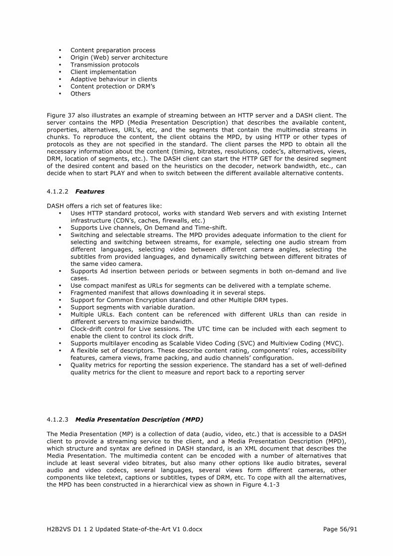
H2B2VS D1 1 2 Updated State-of-the-Art V1 0.docx Page 56/91
• Content preparation process • Origin (Web) server architecture • Transmission protocols • Client implementation • Adaptive behaviour in clients • Content protection or DRM’s • Others
Figure 37 also illustrates an example of streaming between an HTTP server and a DASH client. The server contains the MPD (Media Presentation Description) that describes the available content, properties, alternatives, URL’s, etc, and the segments that contain the multimedia streams in chunks. To reproduce the content, the client obtains the MPD, by using HTTP or other types of protocols as they are not specified in the standard. The client parses the MPD to obtain all the necessary information about the content (timing, bitrates, resolutions, codec’s, alternatives, views, DRM, location of segments, etc.). The DASH client can start the HTTP GET for the desired segment of the desired content and based on the heuristics on the decoder, network bandwidth, etc., can decide when to start PLAY and when to switch between the different available alternative contents.
4.1.2.2 Features DASH offers a rich set of features like:
• Uses HTTP standard protocol, works with standard Web servers and with existing Internet infrastructure (CDN’s, caches, firewalls, etc.)
• Supports Live channels, On Demand and Time-shift. • Switching and selectable streams. The MPD provides adequate information to the client for
selecting and switching between streams, for example, selecting one audio stream from different languages, selecting video between different camera angles, selecting the subtitles from provided languages, and dynamically switching between different bitrates of the same video camera.
• Supports Ad insertion between periods or between segments in both on-demand and live cases.
• Use compact manifest as URLs for segments can be delivered with a template scheme. • Fragmented manifest that allows downloading it in several steps. • Support for Common Encryption standard and other Multiple DRM types. • Support segments with variable duration. • Multiple URLs. Each content can be referenced with different URLs than can reside in
different servers to maximize bandwidth. • Clock-drift control for Live sessions. The UTC time can be included with each segment to
enable the client to control its clock drift. • Supports multilayer encoding as Scalable Video Coding (SVC) and Multiview Coding (MVC). • A flexible set of descriptors. These describe content rating, components’ roles, accessibility
features, camera views, frame packing, and audio channels’ configuration. • Quality metrics for reporting the session experience. The standard has a set of well-defined
quality metrics for the client to measure and report back to a reporting server
4.1.2.3 Media Presentation Description (MPD) The Media Presentation (MP) is a collection of data (audio, video, etc.) that is accessible to a DASH client to provide a streaming service to the client, and a Media Presentation Description (MPD), which structure and syntax are defined in DASH standard, is an XML document that describes the Media Presentation. The multimedia content can be encoded with a number of alternatives that include at least several video bitrates, but also many other options like audio bitrates, several audio and video codecs, several languages, several views form different cameras, other components like teletext, captions or subtitles, types of DRM, etc. To cope with all the alternatives, the MPD has been constructed in a hierarchical view as shown in Figure 4.1-3

H2B2VS D1 1 2 Updated State-of-the-Art V1 0.docx Page 57/91
Source: DASH standard
Figure 38: MPD hierarchical view
• MPD: Describes the whole content and consists of one or several Periods.
• Period: Is a temporal interval, including the identification of the period, the start time and duration and consists of several Adaptation Sets.
• Adaptation Set: Represents a set of interchangeable encoded versions of one or several
media content components. For example, one Adaptation Set can contain the main video, another one the main audio, etc. Other components like subtitles may be in other Adaptation Sets. Each Adaptation Set contains a set of Representations.
• Representation: Is an encoded alternative of the same media component that can vary in
bitrate, resolution, codec, type of audio, channels, etc. or other characteristics. A Representation can include one or more Segments.
• Segment: Contains the media data (chunks) in temporal sequence. Each segment has
duration and an associated URL that allows being downloaded using HTTP GET or HTTP GET with bytes range. Segments may be further subdivided into Subsegments.
• Subsegments: Each contains a whole number of complete media access units.
Using this data model, the DASH client retrieves the MPD and selects, based on player capabilities, user’s choices or other information, the Adaption Sets it wants to play (video + audio + other). Then for each it gets the set of Representations that are encoded and selects the one that can be used depending on the available bandwidth and other factors. Each Representation contains the list
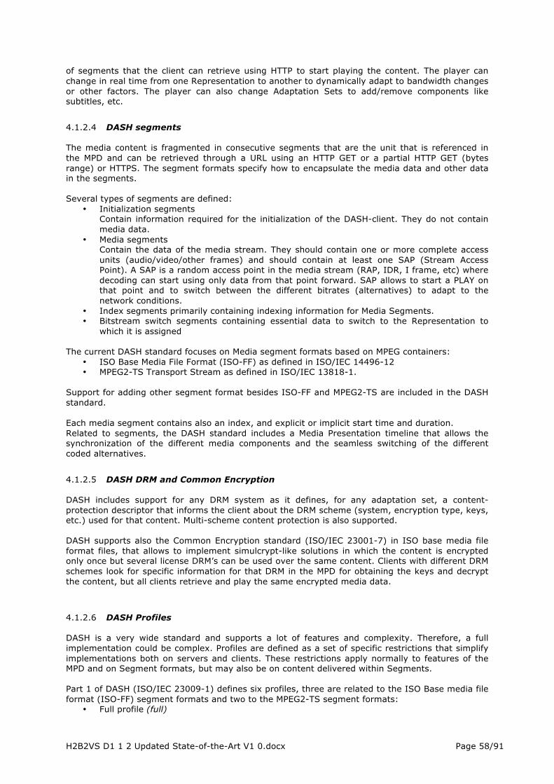
H2B2VS D1 1 2 Updated State-of-the-Art V1 0.docx Page 58/91
of segments that the client can retrieve using HTTP to start playing the content. The player can change in real time from one Representation to another to dynamically adapt to bandwidth changes or other factors. The player can also change Adaptation Sets to add/remove components like subtitles, etc.
4.1.2.4 DASH segments
The media content is fragmented in consecutive segments that are the unit that is referenced in the MPD and can be retrieved through a URL using an HTTP GET or a partial HTTP GET (bytes range) or HTTPS. The segment formats specify how to encapsulate the media data and other data in the segments. Several types of segments are defined:
• Initialization segments Contain information required for the initialization of the DASH-client. They do not contain media data.
• Media segments Contain the data of the media stream. They should contain one or more complete access units (audio/video/other frames) and should contain at least one SAP (Stream Access Point). A SAP is a random access point in the media stream (RAP, IDR, I frame, etc) where decoding can start using only data from that point forward. SAP allows to start a PLAY on that point and to switch between the different bitrates (alternatives) to adapt to the network conditions.
• Index segments primarily containing indexing information for Media Segments. • Bitstream switch segments containing essential data to switch to the Representation to
which it is assigned The current DASH standard focuses on Media segment formats based on MPEG containers:
• ISO Base Media File Format (ISO-FF) as defined in ISO/IEC 14496-12 • MPEG2-TS Transport Stream as defined in ISO/IEC 13818-1.
Support for adding other segment format besides ISO-FF and MPEG2-TS are included in the DASH standard. Each media segment contains also an index, and explicit or implicit start time and duration. Related to segments, the DASH standard includes a Media Presentation timeline that allows the synchronization of the different media components and the seamless switching of the different coded alternatives.
4.1.2.5 DASH DRM and Common Encryption
DASH includes support for any DRM system as it defines, for any adaptation set, a content-protection descriptor that informs the client about the DRM scheme (system, encryption type, keys, etc.) used for that content. Multi-scheme content protection is also supported. DASH supports also the Common Encryption standard (ISO/IEC 23001-7) in ISO base media file format files, that allows to implement simulcrypt-like solutions in which the content is encrypted only once but several license DRM’s can be used over the same content. Clients with different DRM schemes look for specific information for that DRM in the MPD for obtaining the keys and decrypt the content, but all clients retrieve and play the same encrypted media data.
4.1.2.6 DASH Profiles
DASH is a very wide standard and supports a lot of features and complexity. Therefore, a full implementation could be complex. Profiles are defined as a set of specific restrictions that simplify implementations both on servers and clients. These restrictions apply normally to features of the MPD and on Segment formats, but may also be on content delivered within Segments. Part 1 of DASH (ISO/IEC 23009-1) defines six profiles, three are related to the ISO Base media file format (ISO-FF) segment formats and two to the MPEG2-TS segment formats:
• Full profile (full)

H2B2VS D1 1 2 Updated State-of-the-Art V1 0.docx Page 59/91
Includes all the features and segment types of the DASH standard.
• ISO Base media file format On Demand profile (ISOFF-ON-DEMAND) Provide basic support for On-Demand content with efficient use of HTTP servers and simple seamless switching.
• ISO Base media file format live profile (ISOFF-LIVE) Optimized for live encoding and may achieve latency of a few seconds with short Segments, using template generated URL’s and allows simple seamless switching.
• ISO Base media file format main profile (ISOFF-MAIN) Includes ISOFF-ON-DEMAND and ISOFF-LIVE.
• MPEG2-TS main profile (MP2T-MAIN)
Impose little constrain on the Segment format for MPEG2-TS content.
• MPEG2-TS simple profile (MP2T-SIMPLE) It is a subset of the MPEG2-TS main profile. It imposes more restrictions on the content encoding and multiplexing in order to simplify the implementation of the seamless switching.
Source: Qualcomm Incorporated
Figure 39: DASH profiles
Some of these profiles have been designed to provide an easy migration from current proprietary HTTP Adaptive Streaming systems to DASH. In this sense, Apple HLS format is similar to the DASH MP2T-MAIN profile and Microsoft Smooth Streaming and Adobe HDS contents are similar to the ISOFF-LIVE profile.
4.1.2.7 Implementations Many DASH player implementations are now available on the market, such as the DASH VLC plugin of the Institute of Information Technology (ITEC) at Alpen-Adria University Klagenfurt,[27],[28] the open-source (and platform independent) DASH client library libdash [29] and the multimedia framework of the GPAC group at Telecom ParisTech [30] as well as many commercial products. Content generation is possible using MP4Box from GPAC [30] or the wrapper tool DASHEncoder (also of ITEC) [27],[31]. The first DASH server and Android (2.2 to 4.x) SDK player implementation was demonstrated by RealNetworks at the IBC 2012 with the Helix Universal Server and the Helix SDK for Android demonstrating MPEG2-TS (Smart TV) and ISO BMFF (MP4 Smartphone / Tablet) delivery and playback formats commercially available from November 2012 [32]. As of beginning 2015, many commercial solutions to package content into MPEG DASH are available and ready to be deployed.
4.1.2.8 New features developed since the first version of DASH standard has been delivered

H2B2VS D1 1 2 Updated State-of-the-Art V1 0.docx Page 60/91
Since April 1st 2012 when the first version of DASH standard ISO/IEC 23009 Part 1 (Media presentation description and segment formats) was published, several amendments have been developed and gathered into a 2nd version of the ISO/IEC 23009 Part 1. In May 2014, a second edition of ISO/IEC 23009 Part 1 (Media presentation description and segment formats) was published. This second edition adds support for event messages to DASH by providing the server with a mechanism to insert event messages either in the manifest files or in---band along with the media segments. Such event messages make live streaming and ad---insertion application more efficient, robust and flexible. Support of MPD anchors was also added in this edition, which can be used to identify a specific point of play and be used, for instance, to pause streaming of a program in one device and continue the playback of it with another device. MPEG has also finalized Part 2 of MPEG---DASH standard (ISO/IEC 23009---2), conformance files and reference software, which checks the compliancy of manifest and media segments. With this software, the content can be verified to comply with any of the defined MPEG---DASH profiles. This standard also includes a DASH reference client that demonstrates how an MPD is parsed and consequently the segments can be downloaded using HTTP protocol. This part also provides sample DASH client implementations. Finally MPEG has finalized MPEG---DASH Part 3 (ISO/IEC 23009---3) providing a set of informative implementation guidelines for content authoring, client implementation and service deployment. These guidelines recommend best practices for adaptive content authoring for on---demand and live services, enabling trick modes in content authoring, sample client architecture, client timing model implementations, and sample deployment scenarios.
4.1.2.9 The Future DASH standard ISO/IEC 23009 Part 1 (Media presentation description and segment formats) 2nd edition was published in May 2014 and MPEG is now working on new additions that will be materialized by an amendment to the current edition: This amendment will provide a new DASH profile based on ISO-BMFF that addresses the currently known industry needs. Precise calculation of segment availability time is needed in order to operate a robust 24x7 low-latency live service. In case DASH client and a server have different clock origins (e.g., NTP vs GPS), the resulting mismatch may result in miscalculation of segment avail8ability time and eventually an attempt to retrieve a segment that is yet unavailable. This amendment provides mechanisms for synchronizing DASH client and server irrespective of their clock origins. As a complement to the part 1, MPEG is also working to the newly introduced features in the other parts:
• Part 2: Reference software and conformance • Part 3: Implementation guidelines • Part 5: Server and network assisted DASH (SAND)
Regarding the on-going work items in MPEG-DASH, Server and network assisted DASH (SAND) includes new proposals that may be of interest to the H2B2VS project and should therefore be followed. Especially, proposals involving co-use of 3GPP MBMS and DASH in broadcast and hybrid transmission of live multimedia. In general, SAND aims to define operations that improve DASH content delivery in networks. It will allow implementing application and DASH awareness into networks as well as to provide DASH clients knowledge about the network status. There are many possibilities and benefits for SAND usage which have been drafted in the form of use cases by the DASH group. The envisioned SAND operations may involve underlying protocols and network nodes in the end-to-end path, and they are enabled with a message exchange capability between servers, intermediate network nodes (e.g. proxies, caches, CDN, and analytics servers), and DASH clients. In the SAND reference architecture, the network side elements participating in the message exchange (including also the media origin) are called DASH assisting network elements (DANE). By definition, DANEs have at least a minimum intelligence about DASH but may also perform more complex operations that influence DASH content delivery. MPEG is currently specifying the messages and parameters to be supported for enabling SAND operations. In addition, requirements for a transport protocol for carrying the messages will be defined. Some of the parameters are being defined in cooperation with 3GPP in order to enable, for example, flexible usage of eMBMS by

H2B2VS D1 1 2 Updated State-of-the-Art V1 0.docx Page 61/91
the DASH client or simply collecting and using network status information (e.g. bitrate characteristics) in the adaptation decision-making. In the industry MPEG-DASH has been adopted by companies like Adobe, Microsoft, Qualcomm, Akamai, Cisco, Netflix, etc., most of them have been participating actively in the MPEG definition. Other groups and organizations are promoting the use of DASH, adopting it or considering its adoption:
• DASH Industry Forum DASH-IF (formerly DASH-PG): The DASH Promoters Group (DASH-PG) was established in February 2012, by several industry leaders who contributed to the MPEG-DASH standard. Since its membership grew rapidly to over 60 members, the group believed that a formal entity could better serve the promotion of MPEG-DASH and therefore, established the DASH-IF. DASH-IF is an incorporated non-profit organization overseen by its Board of Directors and currently consists of three working groups:
o Interoperability Working Group o Promotion Working Group o Liaison Working Group
• EBU (European Broadcaster Union) • DVB (Digital Video Broadcast) • HbbTV (Hybrid Broadband Broadcast TV), in its newly delivered v2.0 release • 3GPP (Third Generation Partnership Project) • DECE (Digital Entertainment Content Ecosystem)
With this wide adoption it is expected that DASH can be the standard for Internet Adaptive Streaming, enabling efficiency and cost savings for content and service providers and allowing consumers a fast and high-quality streaming experience on any type of device.
4.2 MMT In its history, MPEG has developed many standards in the domain of multimedia delivery, such as MPEG-2 Transport Stream (TS), aimed at supporting real-time streaming delivery, and the ISO Base Media File Format (BMFF), aimed at targeting exchange and progressive download applications. MPEG-2 TS is currently being used for many real-time multimedia services including digital broadcasting, while the ISO BMFF has been widely adopted as a storage format by the Third Generation Partnership Project (3GPP) and Digital Entertainment Content Ecosystem (DECE). In the last years, broadcasting services and mobile services have started converging and it is expected that this convergence trend will include other services in the near future. The rapid increase of multimedia content delivery over the Internet is introducing several new requirements for multimedia delivery: for instance, a greater demand exists for flexible and partial access to media content. Due to its mechanisms to multiplex multiple audio-visual data streams into one delivery stream according to consumption order, MPEG-2 TS is a perfect solution for multimedia streaming to a large number of users. However, it cannot efficiently support typical Internet features, such as personalized advertisement or language audio track switching, since dynamic insertion or multiplexing of advertisements or audio streams requires demultiplexing and remultiplexing streams. The ISO BMFF has a similar challenge in that it stores synchronized playback metadata separately from the compressed media data. However, it is hard to efficiently access a certain subset of the file, for example, to download only an audio stream with a specific language or switch from one to another during playback. [33] Based on the new challenges in multimedia delivery and on the shortcomings of existing standards, MPEG initiated the development of two new standards (DASH and MMT) to improve multimedia delivery over the Internet, particularly focusing on content-centric networks (CCNs). In particular, the MPEG Media Transport (MMT) is being developed as part 1 of ISO/IEC 23008, High Efficiency Coding and Media Delivery in Heterogeneous Environments (MPEG-H). MMT focuses on the use of IP networks with in-network intelligent caches located close to the receiving entities, with the purpose of not only actively caching the contents but also adaptively packetizing and pushing the content to the receiving entities. MMT also relies on a network environment in which the content could be accessed at a finer grain, with uniquely identifiable names instead of just their location. To achieve efficient delivery of MPEG Media data over heterogeneous IP networks, MMT defines encapsulation formats, delivery protocols, and signalling message formats as shown in Figure 40 [34]:
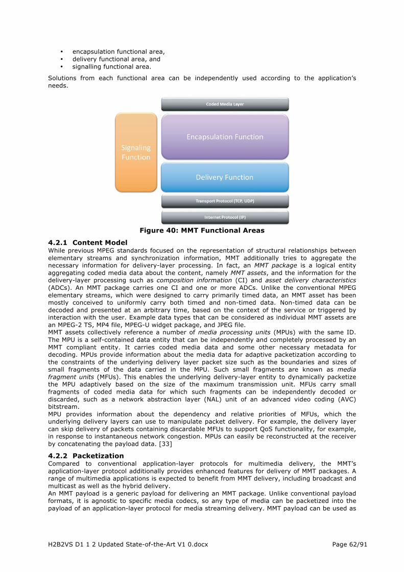
H2B2VS D1 1 2 Updated State-of-the-Art V1 0.docx Page 62/91
• encapsulation functional area, • delivery functional area, and • signalling functional area.
Solutions from each functional area can be independently used according to the application’s needs.
Figure 40: MMT Functional Areas
4.2.1 Content Model While previous MPEG standards focused on the representation of structural relationships between elementary streams and synchronization information, MMT additionally tries to aggregate the necessary information for delivery-layer processing. In fact, an MMT package is a logical entity aggregating coded media data about the content, namely MMT assets, and the information for the delivery-layer processing such as composition information (CI) and asset delivery characteristics (ADCs). An MMT package carries one CI and one or more ADCs. Unlike the conventional MPEG elementary streams, which were designed to carry primarily timed data, an MMT asset has been mostly conceived to uniformly carry both timed and non-timed data. Non-timed data can be decoded and presented at an arbitrary time, based on the context of the service or triggered by interaction with the user. Example data types that can be considered as individual MMT assets are an MPEG-2 TS, MP4 file, MPEG-U widget package, and JPEG file. MMT assets collectively reference a number of media processing units (MPUs) with the same ID. The MPU is a self-contained data entity that can be independently and completely processed by an MMT compliant entity. It carries coded media data and some other necessary metadata for decoding. MPUs provide information about the media data for adaptive packetization according to the constraints of the underlying delivery layer packet size such as the boundaries and sizes of small fragments of the data carried in the MPU. Such small fragments are known as media fragment units (MFUs). This enables the underlying delivery-layer entity to dynamically packetize the MPU adaptively based on the size of the maximum transmission unit. MFUs carry small fragments of coded media data for which such fragments can be independently decoded or discarded, such as a network abstraction layer (NAL) unit of an advanced video coding (AVC) bitstream. MPU provides information about the dependency and relative priorities of MFUs, which the underlying delivery layers can use to manipulate packet delivery. For example, the delivery layer can skip delivery of packets containing discardable MFUs to support QoS functionality, for example, in response to instantaneous network congestion. MPUs can easily be reconstructed at the receiver by concatenating the payload data. [33]
4.2.2 Packetization Compared to conventional application-layer protocols for multimedia delivery, the MMT’s application-layer protocol additionally provides enhanced features for delivery of MMT packages. A range of multimedia applications is expected to benefit from MMT delivery, including broadcast and multicast as well as the hybrid delivery. An MMT payload is a generic payload for delivering an MMT package. Unlike conventional payload formats, it is agnostic to specific media codecs, so any type of media can be packetized into the payload of an application-layer protocol for media streaming delivery. MMT payload can be used as

H2B2VS D1 1 2 Updated State-of-the-Art V1 0.docx Page 63/91
a payload format for both the Real-Time Transfer Protocol (RTP) and MMT Protocol. Additionally, MMT payload can also be used to deliver MMT signalling messages. The MMT Protocol is particularly suited to support the media streaming delivery through heterogeneous IP network environments. The MMT Protocol provides the additional functionality of QoS management of media assets as well as the ability to multiplex various media components into a single flow. MMT’s main focus is on IP-based packet delivery systems, although currently there is interest in utilizing the MMT payload and MMT Protocol for non-IP broadcast delivery systems that are nevertheless still packet-based. [33]
4.2.3 MMT in the Future Internet Even though it is nowadays clear that almost all transport-layer protocols are converging to IP regardless of their characteristics, today’s Internet architecture is not optimal for multimedia services. Therefore, future networks such as CCNs will not only provide a better network architecture for multimedia delivery, but will also require a multimedia transport solution that is more aware of a delivery network’s requirements. MMT address such requirements, both by exposing the detailed information required by the underlying delivery layer that is agnostic to the specific media type and by defining an application-layer protocol that is optimized for multimedia delivery. MMT is currently under development in MPEG and is expected to be published as an international standard in 2014. No specific implementations are available yet, anyway there are already studies concerning methods for providing timing information in MMT hybrid delivery services, such as the study reported at [34], which proposes a timestamp-related header format for MMT timing model to support media synchronization in MMT system based media service; the proposed time stamping service provides for sender/receiver timing matching for synchronization of several media sources. In [35], a method for providing timing information for synchronizing packet streams delivered from a first server and a second server, respectively, which are different from each other when hybrid delivery service environment is provided.
4.2.4 MMT potential future Use Cases Since May2014, MMT is now a full ISO/IEC standard under the name ISO/IEC 23008-1:2014 (Information technology -- High efficiency coding and media delivery in heterogeneous environments -- Part 1: MPEG media transport (MMT)). Other parts of the MMT standard are also very close to a full standardization status like FEC and Composition information. Some preliminary adoption are on the way as it is considered for the future Japanese Satellite broadcast system and some practical implementations has been demonstrated during year 2014 in some MMT implementation forums. MMT is also envisaged as one of the possible implementation of the transport layer currently under definition in the ATSC 3.0 standardisation activities.

H2B2VS D1 1 2 Updated State-of-the-Art V1 0.docx Page 64/91
5 CONTENT PROTECTION, SECURITY 5.1 CAS Human nowadays is witness of the flourish period of the digital era. Hardware and software tools for manipulating, transmitting and storing digitalized multimedia contents become more and more efficient with accessible prices. It is a children’s game to make a copy of a digitalized content and deliver it afterward via a connected network or a physical media support with identical quality. Therefore content protection and Digital Rights Management (DRM) are among those fields that get a lot of attention from content owners and consumers. Content owners require these techniques to protect and maximize their revenues. Consumers want to access their preferred movies with minimum cost, which stimulate the pirate activities, to reproduce the same content with lower prices in comparison with the official suppliers.
Against this challenging situation, there are many solutions already deployed in the market. Ideally, it should incorporate two types of protection, which are complementary and serve the unique purpose of mitigating the misuse of a piece of content. Together they ensure strong protection. Their goals are the following:
1. Proactive protection of content, 2. Reactive protection of content.
The first barrier targets direct attacks on the asset such as theft, alteration and replacement. The associated tools are based on encryption and cryptographic signature. Unfortunately, content can always leak. As a result, the second barrier is needed to attempt to limit the losses that are incurred.
The performance of combining the two protections is superior to the sum of two individual performances. Such combining scheme is referred to as Traitor Tracing Cryptographic scheme. Such traitor tracing schemes tackles typically the following security problem: sometimes, a rogue receiver might share its reception keys, or these reception keys can be publicly leaked after some rogue reverse engineering operation. Hence, it is possible to build clones of a given receiver. Cryptographic traitor tracing schemes aims at identifying the use of leaked keys, or, in other words, tracing traitors. This tracing operation can happen, depending on the scheme, either in a white-box or in a black-box fashion. White-box tracing implies that the rogue keys, or derivate of them, can be accessed by the tracer, which obviously implies some reverse engineering in practice. Black-box tracing is more powerful, as it allows tracing the usage of rogue keys solely by interacting with the rogue receivers and observing whether or not it is able to decrypt a given encrypted A/V stream.
Traitor tracing schemes suffer also from several drawbacks, often of the same type than broadcast encryption schemes. Furthermore, once properly traced, a traitor has to be black-listed, or revoked even sanctioned officially. To perform securely the black listing and revocation, an additional broadcast encryption scheme is inevitable.
For the sake of clarity, in the rest of this section we will review the two protections separately. Two typical subtypes of proactive protection – one deployed in broadcast and another in broadband - are presented in Section 6.1 and 6.2 respectively. Section 6.3 gives a comprehensive study on reactive protection of content, namely Forensic Watermarking.
5.1.1 Proactive protection in Broadcast
Pay television or premium television (Pay-TV) is a concept that has been around since 1951. It is a subscription-based television service, which is distributed over satellite, cable or terrestrial networks. Most of the time, the networks is a broadcasting one, but broadband (i.e., fully connected) distribution has also appeared recently. In order to be able to receive Pay-TV contents, an antenna (or cable TV outlet) and a Set-Top Box (STB) which will descramble, decode and process the A/V content are typically needed. Upon subscription to the content, the customer pays a certain fee and receives a security token, usually a smartcard, which should be inserted into the STB giving access to the Pay-TV Products purchased by the client.
Products consist of one or several Services, where one Service can be seen as a channel. Hence, if a client wants to subscribe to a single channel, he will pay for the subscription for the whole product. Some channels can be individually subscribed to, which technically means that there is a product consisting of a single service. In a broadcast setting, since all the products and services are transmitted on the same shared medium (satellite, terrestrial, cable), there will be two groups of receivers from the point of view of the broadcaster: the authorized receivers and the non-

H2B2VS D1 1 2 Updated State-of-the-Art V1 0.docx Page 65/91
authorized ones. The A/V content should be securely delivered to the authorized clients, which have paid their fees, in a way that prevents the non-authorized users from accessing and seeing the content for free. Because of that, the A/V content, and more specifically each service, is encrypted, or as defined in the Pay-TV community, scrambled. A key point to note is that the encryption key is a global one, as there is a single encrypted A/V stream on the channel, for obvious bandwidth issues reasons. Hence, the main question related to the Pay-TV security is, at first, how to efficiently manage the subscriptions and second, how to securely giving access to the products and services, i.e., transmit the global encryption key to the authorized receivers. This is a particularly delicate task, as a single receiver leaking this global media encryption key destroys the overall system’s security. In a broadband setting, this global encryption key is often replaced with an individualized (or unique) one, as the A/V stream might be sent individually to each receiver. Hence, the security challenges are typically tougher to tackle in a broadcast scenario than in a broadband one.
The Conditional Access System (CAS), which is at the heart of any Pay-TV system, provides a solution to this problem. Moreover, it frequently allows the management of more advanced business models beyond basic access, such as Video-on-Demand (VOD) and impulsive Pay-Per-View (IPPV), just to name a few, but which are not in the scope of this project and document.
In the sequel of this chapter we will give an overview of a Conditional Access System in the case of the Digital Video Broadcasting (DVB) standard, with a focus on the management messages (Entitlement Control Message and Entitlement Management Message) which embed the cryptographic data.
5.1.2 Conditional Access System CAS - the Big Picture
5.1.2.1 The Head-end We will start by performing an overview of the broadcasting side of the CAS. This side is also called the head-end. Figure 1.1 shows some of the principal elements of the head-end and interaction between them. The multiplexer (or simply mux) allows sending A/V signal, data and CAS-related information on a single channel. The resulting stream is called the transport stream. The transport stream is scrambled using an encryption algorithm - and in the case of DVB, this encryption algorithm is called Common Scrambling Algorithm (DVB-CSA). In the DVB terminology, an encryption key is called a Control Word (CW). Eventually, the encrypted transport stream is then sent, through a modulator, into the "air".
H2B2VS D1 1 2 Updated State-of-the-Art V1 0.docx Page 66/91
Figure 41: CAS Overview - Head-end side
The CW is frequently changed: the valid period for a given CW is called the Crypto Period and typically lasts 4 to 60 seconds. It allows a fine granularity for access control, as the crypto-period is the smallest unit of access period. Frequently changing the CW mitigates the threat of a major security breach caused by a potential weakness in the DVB-CSA algorithm; indeed, the algorithm specifications were kept secret from its creation in 1995 until its description leaked in 2002. Short crypto-periods had also the goal to avoid an easy sharing of this content decryption key, before the wide availability of the Internet. The CW itself is encrypted using a service key and sent in Entitlement Control Messages (or ECMs). This service key is uniquely encrypted using the customer key and sent to the client who purchased the given service using Entitlement Management Messages (or EMMs). The management of customers and their access rights is performed through the Subscriber Authorization System (SAS) and Subscriber Management System (SMS), respectively. It is straightforward to deduce from this architecture that the customer of a Pay-TV service will be able to decrypt A/V streams as long as he has a valid service key. Hence the end of an access period (i.e. the end of a movie or the end of a subscription) corresponds to the service key change.
5.1.2.2 The Receiver We will now look at the receiver side of the system illustrated by Figure 1.2. The stream, which consists of scrambled A/V, data and ECM/EMM streams, goes through the demodulator. The Conditional Access Kernel (CAK) filters the relevant ECMs and EMMs and sends them to the security module which is typically a tamper-resistant smart card (SC). If the SC possesses the corresponding rights, the ECMs are decrypted and the CW is delivered to the descrambler. In the case of EMM processing, the EMM is decrypted with the subscriber key and the service keys are securely stored in the key database.
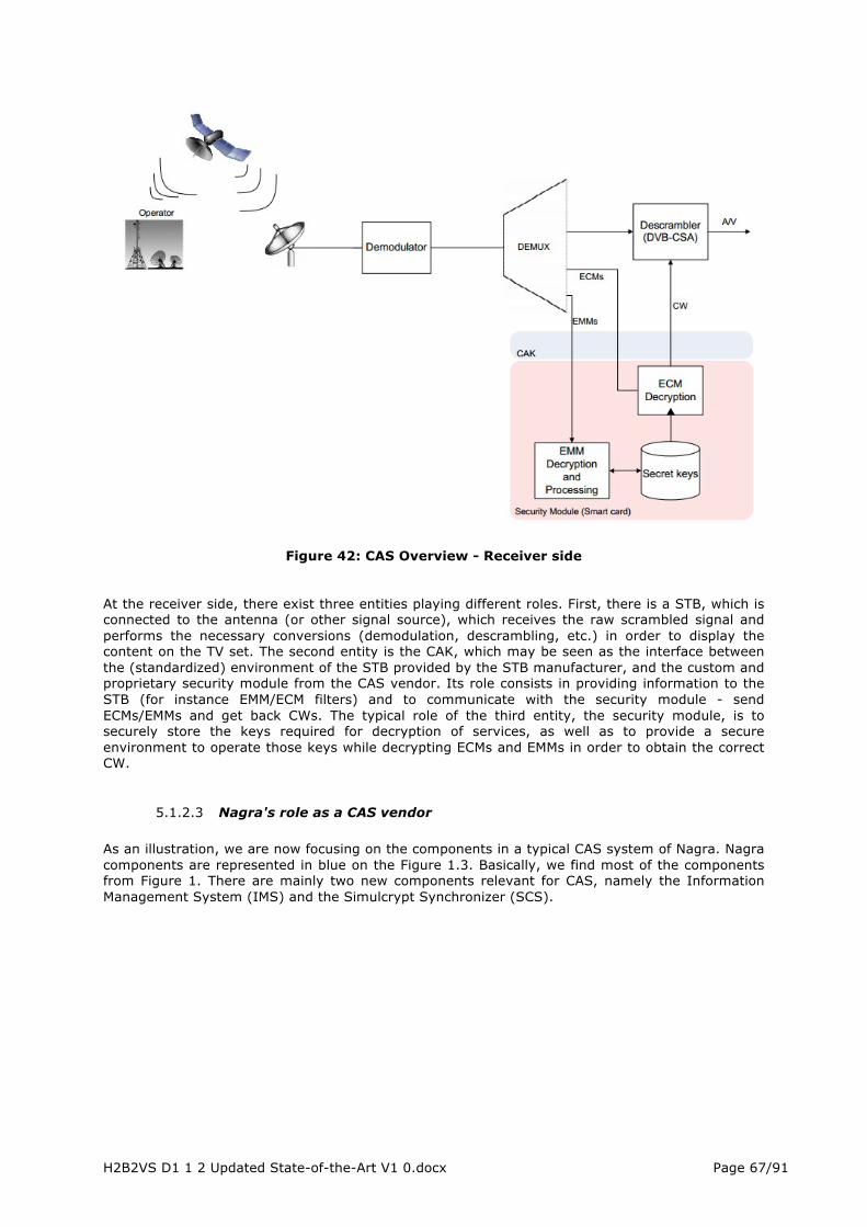
H2B2VS D1 1 2 Updated State-of-the-Art V1 0.docx Page 67/91
Figure 42: CAS Overview - Receiver side
At the receiver side, there exist three entities playing different roles. First, there is a STB, which is connected to the antenna (or other signal source), which receives the raw scrambled signal and performs the necessary conversions (demodulation, descrambling, etc.) in order to display the content on the TV set. The second entity is the CAK, which may be seen as the interface between the (standardized) environment of the STB provided by the STB manufacturer, and the custom and proprietary security module from the CAS vendor. Its role consists in providing information to the STB (for instance EMM/ECM filters) and to communicate with the security module - send ECMs/EMMs and get back CWs. The typical role of the third entity, the security module, is to securely store the keys required for decryption of services, as well as to provide a secure environment to operate those keys while decrypting ECMs and EMMs in order to obtain the correct CW.
5.1.2.3 Nagra's role as a CAS vendor As an illustration, we are now focusing on the components in a typical CAS system of Nagra. Nagra components are represented in blue on the Figure 1.3. Basically, we find most of the components from Figure 1. There are mainly two new components relevant for CAS, namely the Information Management System (IMS) and the Simulcrypt Synchronizer (SCS).

H2B2VS D1 1 2 Updated State-of-the-Art V1 0.docx Page 68/91
Figure 43: Nagra CAS Overview The IMS subsystem is responsible for creating the Pay-TV products and "programming" the relative access criteria into the ECM stream. The SCS plays its role when an operator wishes to employ several CAS from different vendors. It allows saving bandwidth by using the same CW over several CAS solutions. In fact, in this case, there will be several ECM streams per service conveying the same final CW used for scrambling/descrambling the A/V stream. This constraint (i.e. the requirement from the operator to rely on several CAS vendors) imposes a standardized scrambling solution in the form of DVB-CSA. Finally, the ECS component is responsible for CW encryption. The operating environment in the HE can be separated into three domains: on-air, on-line and off-line. The on-air domain is the most critical one, since failure in its operation would instantly result in a black screen on the subscriber's side. The subsystems of this domain are redundant in order to assure at least several hours of continuous broadcasting service if an equipment failure occurs. The on-line components are responsible for creation and control of on-air equipment - all the changes are immediately propagated to the on-air domain. The off-line components are dedicated to data planning and definition; their modification has no impact on the on-air subsystem until publication. The last new component on Figure 1.3 is the return path from the subscriber's STB to the HE. This link allows a one-to-one communication between the STB and the HE, emulating in some way a bidirectional link in a broadcast environment. For instance this link is used to report client's purchases (such as the remaining IPPV credit or debt) to the HE, so that it can be included in the client's bill and to retrieve information from the SC in general. It can be even used to update the rights of the SC. It should be however emphasized that such a link is optional and mostly used for advanced business models. Therefore we will consider that such a link does not exist (the STB is not able to "phone back home") and we cannot rely on it for construction of a basic CAS system.
H2B2VS D1 1 2 Updated State-of-the-Art V1 0.docx Page 69/91
5.1.3 Proactive protection in Broadband (Unicast, multicast)
The so-called Digital Right Management DRM usually protects content delivered over broadband connection using unicast and multicast modes. Although functionally very similar to CAS mentioned above, DRM systems have two significant differences:
1. As DRM have to run on generic computers, they operate in a less trusted environment than does CAS. Not relying on tamper-resistant hardware, the trust model of DRM must rely on software tamper-resistance and easy renewability by forcing the customer to download a new version of the software in the event of a hack.
2. DRM assumes the presence (even temporary) of two-way communication, which enables more flexible license management, and some security controls by the remote server. Therefore a Set-Top-Box equipped with an active return channel can make use of DRM techniques.
Other characteristic of a DRM – not exclusively- is the key-based protection. That means a system where access is defined by the ability to decrypt due to the knowledge of a key. The CAS discussed above belongs to other system, called right-based. In CAS, smart cards can decrypt all the ECMs (i.e. knowing all Service Keys) but will return the CWs only if timestamps and rights descriptors conveyed in the ECMs along with the CWs match the rights descriptors in the smart card database.
It is extremely difficult to find public information describing security features of a DRM. However, some principle key-techniques can be summarized in the followings.
5.1.4 Broadcast Encryption The cryptographic community as addressed the problem of security encrypting data in a broadcast channel in the early nineties, thanks to the works of Berkovits, Fiat and Naor. Since, then, many cryptographic schemes have been proposed in the academic literature. The basic idea behind broadcast encryption consists in distributing individualized keys to the subscribers, i.e., the receivers, and to enforce the access decisions on the head-end side, during the encryption operation. Hence, a receiver not having the right to access a channel just cannot decrypt it, and the security does not rely on the tamper proofness of the security module, but merely on cryptographic assumptions. While very seducing on paper in terms of security, broadcast encryption have two major disadvantages that render them hardly practical: first, they are usually unreasonably demanding in terms of bandwidth and/or computational power and/or key size for systems that might involve millions of subscribers. Indeed, the bandwidth available to the CAS is usually only a small portion of the total available bandwidth. Second, a broadcast encryption scheme cannot be used to encrypt the full A/V stream, due to performance reasons, but only a global session key (i.e., a CW). If this session key leaks, the overall system security is void. As such an attack is typically the scenario of control-word sharing that is frequently encountered in practice, this clearly decreases the interest in pure broadcast encryption schemes.
5.1.5 Stateful Key Hierarchies It is worth noting that the underlying assumption behind the protections in 5.1.1 is that the receivers are stateless. As there is no return path between the HE and the STB, it is not possible to keep a perfect synchronisation between those two entities, or it is much too demanding in terms of bandwidth consumption. When it is possible to ensure that the HE and the STB keep perfectly synchronized, much more efficient schemes, often-called key hierarchies, exist. A new time, those stateful schemes also suffer from the problem of session key, or CW sharing.

H2B2VS D1 1 2 Updated State-of-the-Art V1 0.docx Page 70/91
5.2 Forensic Watermarking
5.2.1 Introduction The digital watermarking technology has been applied to video or audio content for many years already. One of the key applications is forensic marking, which aims at inserting imperceptible serial number within the audio or the video of a content before it is being distributed. This number is made unique to each recipient user. In case this content is found, the source of leakage can be traced back to its origin user, thus providing a powerful deterrent against content theft. Digital watermarking can be used to complement encryption and content access technologies to protect content beyond the digital protection. As long as the content is kept in the digital domain, the content encryption provides strong level of protection. However, when the content flows in the analog domain or if the encryption scheme is broken, watermarking provides a necessary additional level of content protection.
5.2.2 Technology The digital watermarking is leveraging the principle of steganography and allows for the embedding of imperceptible and non-removable information, called the payload, into media data. This payload is, by definition of steganography, only decodable by the sender and the intended recipient. The technology is a trade-off between four parameters:
• Imperceptibility • Robustness • Payload length • Processing complexity
For video, the technology is leveraging psycho-acoustic masking and psycho-visual masking. The human ears and eyes have limit of perceptions (mask) that digital sensors do not have. This property can be used to embed imperceptible data in the audio and video as shown for sound on the diagram below.
Figure 44: Psycho-acoustic masking The research effort started in the mid-nineties and aimed at watermarking still images, then video and finally audio. Many watermark implementations [36] have been developed since then. One of the classic strategies to insert watermarking in MPEG video is to perform modification of the compressed bit stream. This implementation is watermarking the content in a robust way, without the need to process uncompressed video. This technology can be used to watermark MPEG2 DVD content for instance.

H2B2VS D1 1 2 Updated State-of-the-Art V1 0.docx Page 71/91
It consists in modifying slightly DCT coefficients of the MPEG transform. The diagram below is summarizing the high level principles. This technology is coupled with a psycho-visual model so that only DCT coefficients that will not affect video quality are modified.
Figure 45 Principle of content watermarking
This first commercial project was the development of a video watermarking service, dedicated to the tracing if video assets broadcasted on television channels. The Philips Research paper proposed at SPIE1999, A Video Watermarking System for Broadcast Monitoring [37], carried under the European ESPRIT project VIVA (Visual Identity Verification Auditor), provides a good snapshot of this project together with a good bibliography on watermarking. This successful research was enhanced by the development of audio watermarking technologies to address copy protection and monitoring. The paper Audio Watermarking for Monitoring and Copy Protection [38], presented at ACM 2000, describes the research done and performance which were reached by Philips Research in this domain. Finally, the watermark technology was adapted to Digital Cinema. The paper A watermarking scheme for digital cinema [39], from ICIP 2001, summarizes the application field and related challenges. This last paper paved the ground for the forensic watermarking necessary to PayTV protection. The requirements for Digital Cinema are indeed to have a watermarking which is: Imperceptible into high resolution video and audio Operating in third party hardware, distributed in various locations Identifying uniquely the content rendered by each of this hardware Be robust to camcorder capture, compression and internet delivery. All these requirements are necessary in the PayTV ecosystem. However, the PayTV ecosystem brings another level of complexity. The objective of the H2B2VS project for watermarking aims at taking the forensic watermarking technology to the next stage by showing: Low resources consumption to integrate within broadcast and broadband networks Ability to support live and VOD diffusion of PayTV content Secured implementation, by combination with CAS/DRM to enhance protection standard
5.2.3 Initial commercial deployment: forensic watermark as a powerful deterrent
Initial commercial deployment of forensic watermarking is going back in 2003, when the technology was used to address the protection of DVD screeners for Academy Awards after the Content Scrambling System (CSS) of DVD was broken.

H2B2VS D1 1 2 Updated State-of-the-Art V1 0.docx Page 72/91
The watermark was used to support FBI investigation and led to identification of pirates [40], which shutdown this source of piracy. Since then, the forensic watermark has been extensively used by the media and entertainment industry as a deterrent to prevent illegal content sharing.
5.2.4 Deployment of watermarking in the B2B deliveries The technology was progressively applied to tapes, files and streams which are circulated before theatrical release in studios and during movie post-production. This helped greatly reducing piracy occurring in the early life of the content and the related prejudices. The forensic watermarking was then applied to protect content in theatres to discourage camcorder capture. For the first time, the watermarking was part from the beginning of the system specifications. The project of the theaters digitalization [41] consisted of replacing 35mm film delivery and projector, to file delivery and video server. The technology is now deployed in both audio and video content played back by more than 100,000 Cinema screens over the world.
5.2.5 Deployment of watermarking in the B2C deliveries More recently, the watermarking was required to protect premium VOD content also referred as “day and date” release. This is transactional VOD content which is made available at the same time in theatres and PayTV. It is an attempt from the studios to regain the loss made on DVD and Blu-ray sales, which are in steady decline. In this use case, the forensic has to integrate in the PayTV delivery (the content of theatres is already watermarked). The forensic watermarking shall support transactional VoD workflow. The watermark has to be unique per transaction/subscriber so that in the event of an illegal copy, the rogue subscribers can be identified. This topic has been much discussed in 2010 and 2011 as theatres owner pushed back this initiative to maintain their exclusivity. However, this exclusivity is creating “content windowing” which is fostering piracy. In the long run, such commercial offering is inevitable and the time between the theatrical window and Home Video is dramatically reducing.
Figure 46: Exclusivity period of movies
The core business of PayTV operators is the live broadcast of exclusive and premium content (for instance sport events) with the best quality of experience. These contents are increasingly shared illegally over the internet, with a quality of service which is continuously improving, creating massive prejudice to the media and entertainment industry [42].

H2B2VS D1 1 2 Updated State-of-the-Art V1 0.docx Page 73/91
Forensic watermarking can solve this problem, which is removing the pirate impunity. The infringers will know they can be traced back and prosecuted. The watermarking of such live content requires a new generation of watermarking, which will integrate seamlessly into live and hybrid workflows. H2B2VS project will further integrate watermarking into the business of live PayTV. In return, the products created will allow operators to invest safely in the production of high value content (such as Ultra HD and 3D) as the watermark will protect their return on investment by discouraging the piracy.

H2B2VS D1 1 2 Updated State-of-the-Art V1 0.docx Page 74/91
6 QUALITY OF EXPERIENCE In the domain of communication technology, the notion of quality has been associated to the so-called ‘Quality of Service’ (QoS) for many years. The formal definition of QoS provided by ITU-T in Rec. E.800 [43] is as follows: “the ability of a network or network portion to provide the functions related to communications between users”. In the recent years, the main motivation towards the adoption of the QoE concept has been the basic that QoS is not powerful enough to fully express everything nowadays involved in a communication service. Hence, in the last years, the term Quality of Experience has been extensively discussed in research literature, normally referring to the user satisfaction during service consumption, i.e., “the subjective quality perceived by the user when consuming audio-visual content” (usually named Perceived QoS or PQoS) [44]. In [45] the QoE is additionally affected by environmental, psychological, and sociological factors such as user expectations and experience. Recently, [46] proposes to define QoE as “the degree of delight or annoyance of the user of an application or service”.
6.1 QoS/QoE Assessment Methods Two basic approaches exist for assessing the QoE:
• subjective assessment as formalized by the ITU-R recommendation BT.500-1 [47] which suggests experimental conditions such as viewing distance and conditions (room lighting, display features, etc.), selection of subjects and test material, assessment and data analysis methods. The tests are performed by employing a panel with evaluators, assessing the quality of a series of short video sequences according to their own personal opinion. The output is the quality of the sequences as seen by an average observer and is usually expressed as a Mean Opinion Score (MOS typically ranging from 1 – bad – to 5 – excellent);
• objective assessment, that is being widely adopted in the industry since the preparation and execution of subjective tests is costly and time consuming. The objective evaluation methods involve the use of algorithms and formulas, measuring the quality in an automatic, quantitative, and repeatable way, based on either signal processing algorithms or network-level quantitative measurements.
Three main methods exist in literature for the evaluation of video quality estimation: 1. Full Reference: to be adopted when the original and processed videos are both available. 2. No Reference: to be adopted when only the processed video is available. 3. Reduced Reference: to be adopted when information about the original and processed
videos is available, but not the actual video sequences.
Most of the quality metrics proposed in the literature are Full Reference metrics, that is, original and distorted videos have to be available to measure the quality. These metrics estimate the quality of a video by comparing reference and impaired videos. Many metrics can be measured against subjective analysis, and VQEG “Video Quality Experts Group”, in conjunction with the ITU-T, published the results as ITU COM 9-80-E [48]. The Full Reference Objective Metrics are:
• PSNR -- Peak Signal to Noise Ratio • JND -- Just Noticeable Differences • SSIM -- Structural SIMilarity • VQM -- Video Quality Metric.
The Reduced-Reference metrics require only partial information about the reference video. In general, certain features or physical measures are extracted from the reference and transmitted to the receiver as side information to help evaluate the quality of the video. Some examples of Reduced-Reference metrics are:
• Objective video quality assessment system based on human perception • Local Harmonic Strength (LHS) metric.
The No-Reference model does not require any information of the original video sequence, which only makes a distortion analysis of the decoded video sequence to assess its quality and the characteristics of the channel. The main goal of each No-Reference approach is to create an estimator based on the proposed features that would predict the MOS of human observers, without using the original image or sequence data. And since the model does not require any comparison of signals, the calculations can be performed in near real-time. As examples of No-Reference models, we can cite:

H2B2VS D1 1 2 Updated State-of-the-Art V1 0.docx Page 75/91
• Blockiness Metrics [49] • Perceptual video quality assessment based on salient region detection [50] • MintMOS [51]
From the analysis of the above three group of metrics (Full-Reference, Reduced Reference and No-Reference), it is obvious that Full Reference model is only applicable at the encoder side, where the original video sequence is available; as for the Reduced Reference model and No-Reference model, especially the latter, they are extremely suitable for the wireless and IP video services where the original reference sequences are absent. Industry normally focuses on No-Reference methods for the objective assessment and on the Full Reference methods for their validation. The validation tests are conducted in compliance with the ITU Recommendation BT.500-11 [47], using the Double Stimulus Impairment Scale (DSIS) method. According to the DSIS method, reference content has to be submitted to the audience together to the one encoded by the system under evaluation. For video services, among the most relevant metrics we can mention:
• start-up time, indicating the delay needed to start up the video service, • start-up failure, indicating the failure rate of a video delivery system, • buffering-ratio, indicating the percentage of time spent in buffering, • average-bitrate, indicating the average bandwidth occupation of video data, and • quantization parameter, which is a good reference for measuring the level of distortion of
encoded video.
6.2 Existing Tools for QoS/Client-side session monitoring Several client-side session monitoring tools exist for both commercial and research purposes. Most of them are implementations of specific models, conceived for traditional VoIP and video streaming applications and operating at various layers (e.g., network, application). Among the commercial tools, various solutions are currently available:
• VTT [52], who has developed a mobile service quality measurement tool (MOSET), which can be used in commercial mobile devices. The tool is designed for measuring the end-to-end service response time (delay), between a mobile device and a server over the networks, from the user point of view.
• Telchemy [54], who developed tools to monitor and manage the performance of VoIP, video over IP and other real time services.
• Shenick [55], who developed diversifEye, providing voice and video quality assessment metrics, active and passive, based on ITU-T J.144 [63], but are extended to support IP networks.
• Agama [56], who developed a monitoring probe for IP and hybrid digital terrestrial/cable networks.
• Conviva [57], who developed the Quality Insight tool, to be integrated with video streaming solutions, establishing thresholds for quality and then receive real-time automatic notifications when video quality drops below in order to take actions to save your valuable viewers. We even help you see where the breakdown is coming from for fast correction. One of the most valuable benefits of Quality Insights is the complete visibility into the entire video delivery chain. It allows you to isolate issues to see if disruptions are being cause by the viewer’s local environment or if the wider Internet is the cause.
• Cedexis [58], who developed tools for evaluating the performances of web-based services (e.g., clouds systems), with the purpose of enabling adaptive automation.
• Alcatel Lucent [59], which developed the AppGlide Video Analytics service, with the purpose of equipping broadband providers with online video analytics that measure end-user quality of experience (QoE) and uncover content delivery issues.
6.3 Existing Tools for QoS/QoE Evaluation - Server/Network-side monitoring (probes)
Several commercial monitoring probes exist in the market, for both server and network QoS monitoring:
• JDSU [53], who developed a Quality Management System for end-to-end QoS management and the PVA-1000 VoIP Network Analysis Suite, which provides analysis of VoIP calls including jitter and packet loss but lacks one way delay.

H2B2VS D1 1 2 Updated State-of-the-Art V1 0.docx Page 76/91
• Sandvine [60], who provides a unified platform for fixed, mobile and converged communications service providers (CSPs) to efficiently deliver many integrated solutions, quickly and with low total cost of ownership.
• Avvasi [61], who developed a solution (Q-VUE and Q-SRV) that allows a scalable, real-time measurement of video Quality of Experience (QoE). Such a solution is able to break down video traffic by device, source, content, media format, media duration and network topology.
• Witbe [62], who developed a set of quality monitoring agents (robots, probes) to analyze network traffic and collect metrics at all levels of the delivery chains, making everybody able to evaluate both network and equipment performance and the quality of services actually delivered to customers.
In the research field, various methods for QoS monitoring have been described in literature [63][64], such as:
• RMON2 probe [65], which monitors and decodes protocols operating at higher layers than the network layer. This provides application-level monitoring.
• Mourelatou et al. [66] introduced a QoS monitoring method in which agents monitor the end-to-end QoS and provide the management system with this information in order to trigger management decisions.
• RTCP (Real Time Control Protocol) [67] also provides the tools to perform end-to-end QoS monitoring, since the RTCP packets contain the fields, such as timestamps, which can be used to calculate QoS parameters.
Ehab Al-Shaer [68] has developed an agent-based QoS monitoring method for multimedia networks.
6.4 QoS/QoE Assessment for MPEG DASH-based services Traditional solutions for objective assessment of quality of real-time services are typically conceived for traditional VoIP and video streaming applications, which are built on UDP as a transport level protocol, and rely on RTP/RTCP for the transfer of real-time data, both favouring timeliness over reliability. Moreover, most of the relevant QoS/QoE models, such as the one described in [69], do not address the problem of measuring QoE in the case of adaptive bitrate video, i.e., switching among different media representations has in fact an impact on perceived quality. Due to the recent success of HTTP as a protocol for providing multimedia transmission, the content providers are being increasingly interested in evaluating the quality of TCP/HTTP-based services. For such services, the traditional QoS/QoE models are not suitable anymore, due to the different transmission model. For example, QoS parameters such as packet loss rate and packet delay do not apply to TCP-based services. On the contrary, parameters such as buffer underflow/overflow, filling rate, initial delay, etc. have to be taken into account. With the exception of very few public works such as [70], the literature on QoE for HTTP based media streaming is still in its infancy. Hence, new challenges face the QoE monitoring in order to address the TCP/HTTP-based services.
H2B2VS D1 1 2 Updated State-of-the-Art V1 0.docx Page 77/91
7 TERMINALS FOR HYBRID DISTRIBUTION
7.1 Fixed terminals Terminals, namely TVs and Set Top Boxes (STBs), are the closest points to the end-user where the interactivity with the end-user is initiated. In order to deliver all the innovations and developments successfully to the end-user the terminals have to be designed by closely following the entire system and the related standards. It is worth mentioning that the portability, the price and the easy management make the STBs the first terminals where the new technological improvements are implemented in. TVs and STBs which are capable of reception of digital TV and, in particular, high definition broadcasting in the home has been evolving parallel to the DVB standards over the last decade. On the other hand, Internet TV and the delivery of multimedia content to the home user via the Internet have been also becoming increasingly common. HbbTV is intended to extend the reach of multimedia content directly to the television set in a seamless, viewer-friendly manner and to enable the TV viewer to more conveniently access both broadcast digital content (especially HD) and Internet multimedia content (including Internet TV and IPTV) on a TV set using a single remote control/box and a single on-screen interface. Since the beginning of 2010, there are several hybrid TVs and STBs capable of receiving services from both broadcast and internet (broadband) are available in the market.
. HbbTV is both an industry standard (ETSI TS 102 796) and promotional initiative for hybrid digital TV to harmonise the broadcast, IPTV, and broadband delivery of entertainment to the end consumer through connected TVs and STBs.
7.1.1 HbbTV STB market Several countries worldwide, and in Europe in particular, have adopted the HbbTV standard and/or operated HbbTV services and trials. As at December 2011, HbbTV services are in regular operation in France, Germany and Spain, with announcements of adoption in Austria, Czech Republic, Denmark, Netherlands, Poland, Switzerland, Turkey, and trials in Australia, China, Japan, and the US. Since the beginning of 2010 a new generation of advanced HbbTV IPTV set-top box has emerged in the UK with the advent of DVB-T2 services. DVB-T2 tuners enable the reception of free-to-air terrestrial high definition programs to be received in around twelve areas of the UK. High definition digital terrestrial services have encouraged a range of device manufacturers to launch new hybrid set-top boxes for the UK consumer retail market. Some of these companies have launched devices that, in addition to allowing traditional broadcast and IP-delivered services to be received, have an integrated smart-card slot that allows consumers to receive encrypted Premium television services including sports and movies. Such boxes enable the aggregation of traditional linear TV broadcasts with video delivered via both managed (cable) and unmanaged IP networks (the internet). This allows viewers to view broadcast television and internet video on their flat screen TVs, alongside advanced interactive services, such as Video on Demand, internet browsing and time-shifted TV.
7.1.2 Overview of the Hbb TV standardization efforts HbbTV is adopted as standard by ETSI. The HbbTV specification was developed by industry members of the consortium and is based on elements of existing standards and web technologies including the Open IPTV Forum, CEA, DVB, and W3C. The standard specification has been submitted by the end of November 2009 to ETSI, who published it under reference ETSI TS 102 796 in June 2010. There is an accompanying Test Suite that provides a set of test material to test HbbTV device implementations, suitable for manufacturers of devices, including software and hardware components that implement the HbbTV specification (ETSI TS 102 796 v1.1.1). In November 2012 Digital TV Labs became the first Registered Test Centre. Issued HbbTV specifications so far are as the following,
• HbbTV v1.0 which is defining signalling, transport, and presentation of enhanced and interactive applications designed for running on hybrid terminals, (TS 102 796 version 1.1.1)
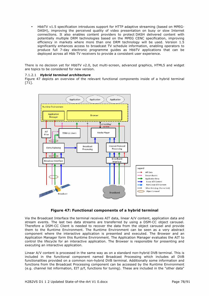
H2B2VS D1 1 2 Updated State-of-the-Art V1 0.docx Page 78/91
• HbbTV v1.5 specification introduces support for HTTP adaptive streaming (based on MPEG-DASH), improving the perceived quality of video presentation on busy or slow Internet connections. It also enables content providers to protect DASH delivered content with potentially multiple DRM technologies based on the MPEG CENC specification, improving efficiency in markets where more than one DRM technology will be used. Version 1.5 significantly enhances access to broadcast TV schedule information, enabling operators to produce full 7-day electronic programme guides as HbbTV applications that can be deployed across all Hbb TV receivers to provide a consistent user experience.
There is no decision yet for HbbTV v2.0, but multi-screen, advanced graphics, HTML5 and widget are topics to be considered for new version.
7.1.2.1 Hybrid terminal architecture Figure 47 depicts an overview of the relevant functional components inside of a hybrid terminal [71].
Figure 47: Functional components of a hybrid terminal
Via the Broadcast Interface the terminal receives AIT data, linear A/V content, application data and stream events. The last two data streams are transferred by using a DSM-CC object carousel. Therefore a DSM-CC Client is needed to recover the data from the object carousel and provide them to the Runtime Environment. The Runtime Environment can be seen as a very abstract component where the interactive application is presented and executed. The Browser and an Application Manager form this Runtime Environment. The Application Manager evaluates the AIT to control the lifecycle for an interactive application. The Browser is responsible for presenting and executing an interactive application. Linear A/V content is processed in the same way as on a standard non-hybrid DVB terminal. This is included in the functional component named Broadcast Processing which includes all DVB functionalities provided on a common non-hybrid DVB terminal. Additionally some information and functions from the Broadcast Processing component can be accessed by the Runtime Environment (e.g. channel list information, EIT p/f, functions for tuning). These are included in the "other data"

H2B2VS D1 1 2 Updated State-of-the-Art V1 0.docx Page 79/91
in Figure 48. Moreover an application can scale and embed linear A/V content in the user interface provided by an application. These functionalities are provided by the Media Player. In Figure 48 this includes all functionalities related to processing A/V content. Via the Broadband Interface the hybrid terminal has a connection to the Internet. This connection provides a second way to request application data from the servers of an application provider. Also this connection is used to receive A/V content (e.g. for Content on Demand applications). The component Internet Protocol Processing comprises all the functionalities provided by the terminal to handle data coming from the Internet. Through this component application data is provided to the Runtime Environment. A/V content is forwarded to the Media Player which in turn can be controled by the Runtime Environment and hence can be embedded into the user interface provided by an application [71].
7.1.3 A reference hardware architecture of a hybrid STB and HEVC decoding capability
Let’s study a reference hybrid STB hardware architecture. It is mainly composed of the following components as illustrated in Figure 48:
• Power board • Front panel • Back panel • Front-end • Back-end
Figure 48 Components of a hybrid STB hardware architecture
Power board is the power supply of the whole hardware platform. It feeds several different power levels to the different the hardware components via transforming the AC voltage. In the front panel, there are the key buttons, STB display, IR for the remote control and USB port and Smart Card ports. The back panel is composed of the AV output together with Ethernet, HDMI, TV Scart input and output ports. The most important parts of a STB hardware are the back-end and the front-end. The front-end, which contains the tuner and the demodulator will be different depending on the transmission

H2B2VS D1 1 2 Updated State-of-the-Art V1 0.docx Page 80/91
media. Hence if a STB is to be made interoperable across all the three transmission media it should be fitted with switchable front ends. The back-end is the part where all the intelligence of the STB comes from via the main chipset. Figure 49 shows the block diagram of the main chipset processes.
Figure 49 Block diagram of a chipset capable of a hybrid STB
TVs and STBs decode video by hardware decoder inside main chipset located on terminal hardware. Limited CPU load occurs during video decoding depending on chipset architecture. Therefore, there will be performance criteria to check response to user actions for terminals during HEVC video decoding. When HEVC is finalized, chipset vendors will design TV and STB chipsets having HEVC codec box. TV and STB terminals capable to decode HEVC videos coming from broadcast or broadband will be realized for end users.
7.1.4 A reference software architecture of a hybrid STB and HEVC decoding capability
Operating system in the STB talks with present hardware and manages their functions such as scheduling real time tasks, managing limited memory resources, etc. STB OS is present in the Kernel layer, which is stored in ROM. Typically the kernel is responsible for managing memory resources, real time applications and high-speed data transmission. It also supports multi-threading and multi-tasking which allows a STB to execute different sections of a program and different programs simultaneously. At present there is no standard STB OS. Many broadcasters and consumer electronics companies are continuing to promote their own in-house solutions. STB requires “drivers” to control the various hardware devices. Driver is a program that translates commands, which are recognizable by the hardware device. To develop any application on the OS an Application Program Interface (API) or middleware are required. In order to make STB interoperable and have universal software architecture, software architecture has been proposed by the DVB project. This is called as Multimedia Home Standard (MHP). MHP reference model is shown in Figure 50.

H2B2VS D1 1 2 Updated State-of-the-Art V1 0.docx Page 81/91
Figure 50: MHP reference model
Figure 51: An example of software architecture of a hybrid STB
The middleware is ported to several DVB platforms using the integration interface. This layer comprises an API, which provides the OS abstraction layer, and another API, which provides access to the hardware device drivers. In this reference middleware architecture, the middleware is mainly composed of the following parts:
• DVB Zapper Stack • MHEG-5 Engine • Over Air Download (OAD) Module • Common Interface Stack • CI+ Stack • HBBTV
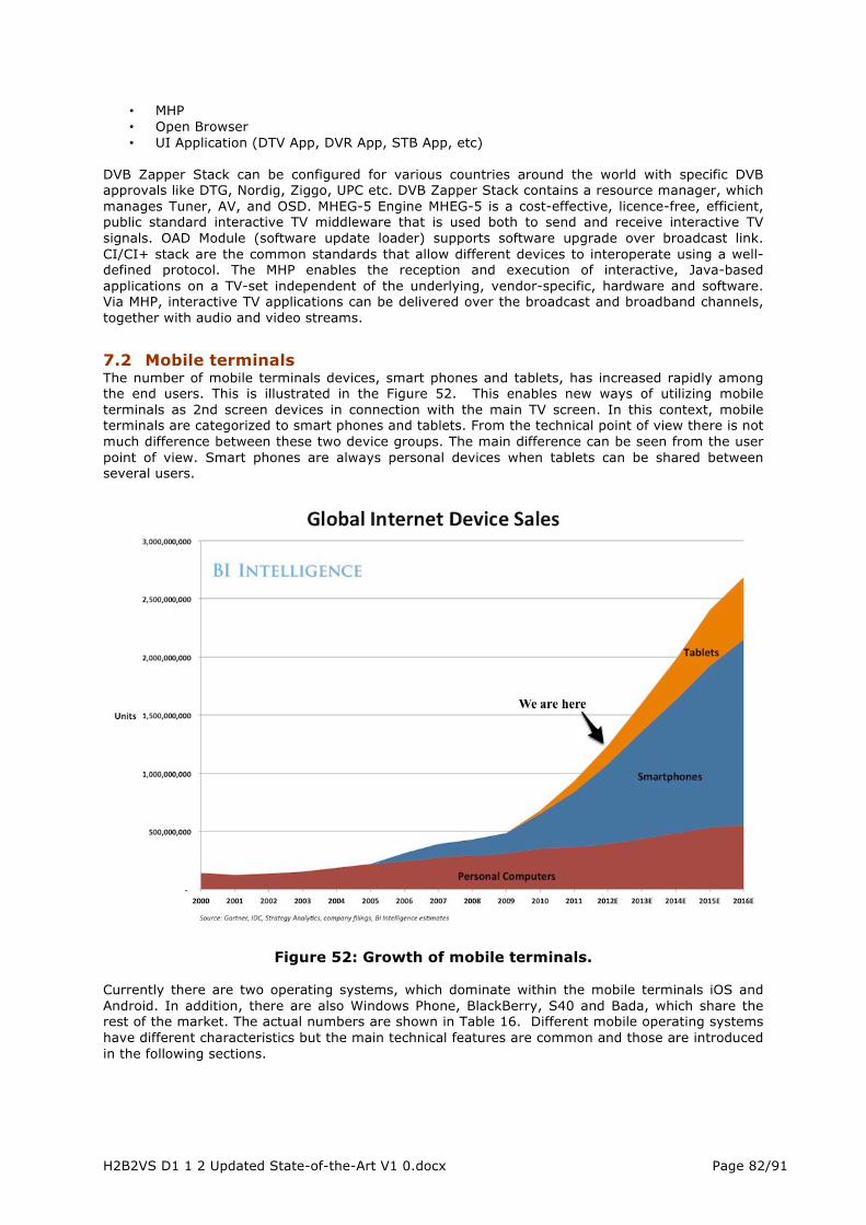
H2B2VS D1 1 2 Updated State-of-the-Art V1 0.docx Page 82/91
• MHP • Open Browser • UI Application (DTV App, DVR App, STB App, etc)
DVB Zapper Stack can be configured for various countries around the world with specific DVB approvals like DTG, Nordig, Ziggo, UPC etc. DVB Zapper Stack contains a resource manager, which manages Tuner, AV, and OSD. MHEG-5 Engine MHEG-5 is a cost-effective, licence-free, efficient, public standard interactive TV middleware that is used both to send and receive interactive TV signals. OAD Module (software update loader) supports software upgrade over broadcast link. CI/CI+ stack are the common standards that allow different devices to interoperate using a well-defined protocol. The MHP enables the reception and execution of interactive, Java-based applications on a TV-set independent of the underlying, vendor-specific, hardware and software. Via MHP, interactive TV applications can be delivered over the broadcast and broadband channels, together with audio and video streams.
7.2 Mobile terminals The number of mobile terminals devices, smart phones and tablets, has increased rapidly among the end users. This is illustrated in the Figure 52. This enables new ways of utilizing mobile terminals as 2nd screen devices in connection with the main TV screen. In this context, mobile terminals are categorized to smart phones and tablets. From the technical point of view there is not much difference between these two device groups. The main difference can be seen from the user point of view. Smart phones are always personal devices when tablets can be shared between several users.
Figure 52: Growth of mobile terminals. Currently there are two operating systems, which dominate within the mobile terminals iOS and Android. In addition, there are also Windows Phone, BlackBerry, S40 and Bada, which share the rest of the market. The actual numbers are shown in Table 16. Different mobile operating systems have different characteristics but the main technical features are common and those are introduced in the following sections.

H2B2VS D1 1 2 Updated State-of-the-Art V1 0.docx Page 83/91
Table 16 Worldwide Mobile Device Sales to End Users by Operating System in 3Q12 (Thousands of Units)
Operating System 3Q12 Units 3Q12 Market Share (%)
3Q11 Units 3Q11 Market Share (%)
Android 122,480.0 72.4 60,490.4 52.5 iOS 23,550.3 13.9 17,295.3 15.0 Research In Motion 8,946.8 5.3 12,701.1 11.0 Bada 5,054.7 3.0 2,478.5 2.2 Symbian 4,404.9 2.6 19,500.1 16.9 Microsoft 4,058.2 2.4 1,701.9 1.5 Others 683.7 0.4 1,018.1 0.9 Total 169,178.6 100.0 1 15,185.4 100.0 Source: Gartner (November 2012)
7.2.1 Software Architecture In Figure 53 the architecture of Android operations system is presented as example architecture for mobile terminal device. It contains the basic building blocks, which can be found from the other operating systems as well. The bottom layer is Kernel or Core OS, which includes also the drivers. Kernel structure is dependent on the hardware foundation, which will vary on different devices. On top of kernel there are application or core frameworks and necessary libraries. The purpose of this layer is to abstract the complexity of many operations from the application developers. In addition, application framework also contains the UI framework. UI framework takes care for example window management, animations and touch gestures. The most top layer is application layer, which contains the readymade applications and application developed by 3rd party. Application developers are limited to the upper blue area, illustrated in the architecture picture.
Figure 53: Android operating system architecture
7.2.2 Connectivity Mobile terminals have several ways to connect to its surroundings. This can include local connections inside buildings such as WLAN or mobile data connections to external cloud services. In the following list there are listed different connectivity technologies, which can be found from common mobile terminals nowadays:
• EDGE • GPRS

H2B2VS D1 1 2 Updated State-of-the-Art V1 0.docx Page 84/91
• HSDPA • HSUPA • LTE • WLAN • Bluetooth • microUSB • NFC • HDMI
What the terminals are missing is the broadcast receiving capability. On the markets three have been devices with DVB-H capability. However, the lack of mobile broadcast networks has removed terminals with broadcast receiving capability from the markets. There are separate dongles which can add e.g. DVB-T/H, T-DMB, CMMB or SBTVD receiving capability for mobile terminals. Dongles or WLAN based additional devices raises two problems:
1) Additional dongle or device is needed and that makes this system impractical especially for smart phones. Users don’t want to carry additional stuff with them
2) Dongles are usually proprietary systems and no 3rd party applications can be built on top of those.
7.2.3 Screen Mobile terminal have limited screen size compared to main screen. This must be taken into account when designing applications for second screen. Small screen typically shows some additional and maybe personalized information related to the main screen. Meaning that typical user doesn’t want to watch the small screen all the time, but see additional value adding information related to the main show. On the other hand, more advanced display technologies can be used because of the small screen size, the manufacturing costs are much cheaper. The smart phones have typically screen size between 4” and 5” Whereas tablets have screen sizes between 7”and 10”. It can be said that smartphones' screen sizes increase and tablets' screen sizes are getting smaller. The mobile terminals are equipped with multi touch screens and some screens are also optimized to be used with pen. There are several types of screen technologies used in personal devices. Here are listed some of the most common:
• TFT-LCD • IPS-LCD • Super-LCD • OLED • AMOLED • Super AMOLED • Super AMOLED Plus • Super AMOLED HD
7.2.4 Audio and video There is great variety of audio and video codecs, which are supported in terminals. There are already some proprietary solutions for HEVC codec already but it is not included in any standard platform delivery in mobile terminals. The most common protocols and standards, which can be found from Android platform and from many terminal devices, are following: Table 17 Multimedia protocols in Android platform: TYPE FORMAT/CODEC ENCODER DECODER SUPPORTED FILE
TYPE(S) / CONTAINER FORMATS
Video H.263 Yes Yes • 3GPP (.3gp) • MPEG-4 (.mp4)
H.264 AVC Yes Yes • 3GPP (.3gp) • MPEG-4 (.mp4) • MPEG-TS (.ts)
MPEG-4 SP No Yes 3GPP (.3gp) VP8 No Yes • WebM (.webm)
• Matroska (.mkv) Audio AAC LC Yes Yes • 3GPP (.3gp)
• MPEG-4 (.mp4, .m4a) HE-AACv1 (AAC+) Yes Yes

H2B2VS D1 1 2 Updated State-of-the-Art V1 0.docx Page 85/91
HE-AACv2 (enhanced AAC+)
No Yes • ADTS raw AAC (.aac) • MPEG-TS (.ts)
AAC ELD (enhanced low delay AAC)
Yes Yes
AMR-NB Yes Yes 3GPP (.3gp) AMR-WB Yes Yes 3GPP (.3gp) FLAC No Yes FLAC (.flac) MP3 No Yes MP3 (.mp3) MIDI No Yes • Type 0 and 1 (.mid, .xmf,
.mxmf) • RTTTL/RTX (.rtttl, .rtx) • OTA (.ota) • iMelody (.imy)
Vorbis No Yes •Ogg (.ogg) • Matroska (.mkv)
PCM/WAVE Yes Yes WAVE (.wav) Considering the video encoding in the current mobile terminals following encoding parameters is used for H.264 in Android platform: Table 18 Video encoding parameters in Android platform SD (LOW QUALITY) SD (HIGH QUALITY) HD Video codec H.264 Baseline Profile H.264 Baseline Profile H.264 Baseline Profile Video resolution 176 x 144 px 480 x 360 px 1280 x 720 px Video frame rate 12 fps 30 fps 30 fps Video bitrate 56 Kbps 500 Kbps 2 Mbps Audio codec AAC-LC AAC-LC AAC-LC Audio channels 1 (mono) 2 (stereo) 2 (stereo) Audio bitrate 24 Kbps 128 Kbps 192 Kbps
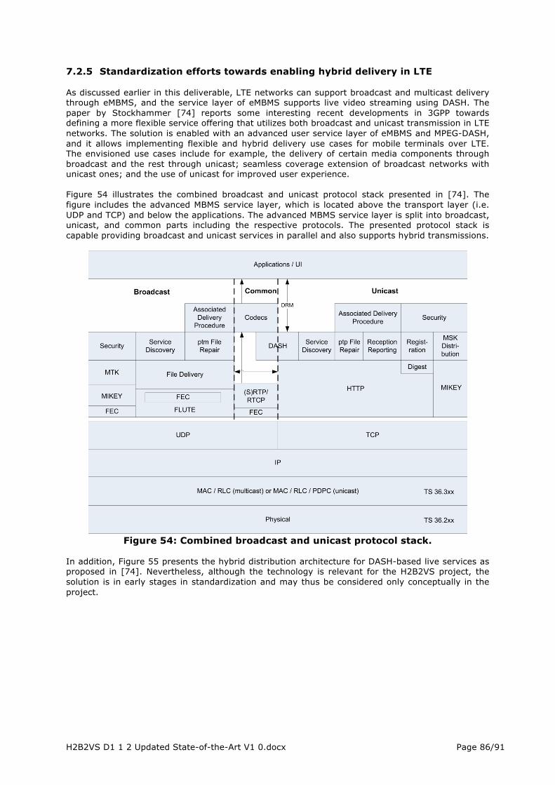
H2B2VS D1 1 2 Updated State-of-the-Art V1 0.docx Page 86/91
7.2.5 Standardization efforts towards enabling hybrid delivery in LTE As discussed earlier in this deliverable, LTE networks can support broadcast and multicast delivery through eMBMS, and the service layer of eMBMS supports live video streaming using DASH. The paper by Stockhammer [74] reports some interesting recent developments in 3GPP towards defining a more flexible service offering that utilizes both broadcast and unicast transmission in LTE networks. The solution is enabled with an advanced user service layer of eMBMS and MPEG-DASH, and it allows implementing flexible and hybrid delivery use cases for mobile terminals over LTE. The envisioned use cases include for example, the delivery of certain media components through broadcast and the rest through unicast; seamless coverage extension of broadcast networks with unicast ones; and the use of unicast for improved user experience. Figure 54 illustrates the combined broadcast and unicast protocol stack presented in [74]. The figure includes the advanced MBMS service layer, which is located above the transport layer (i.e. UDP and TCP) and below the applications. The advanced MBMS service layer is split into broadcast, unicast, and common parts including the respective protocols. The presented protocol stack is capable providing broadcast and unicast services in parallel and also supports hybrid transmissions.
Figure 54: Combined broadcast and unicast protocol stack.
In addition, Figure 55 presents the hybrid distribution architecture for DASH-based live services as proposed in [74]. Nevertheless, although the technology is relevant for the H2B2VS project, the solution is in early stages in standardization and may thus be considered only conceptually in the project.
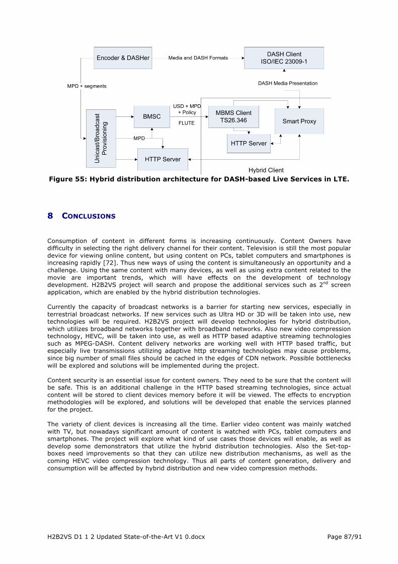
H2B2VS D1 1 2 Updated State-of-the-Art V1 0.docx Page 87/91
Figure 55: Hybrid distribution architecture for DASH-based Live Services in LTE.
8 CONCLUSIONS Consumption of content in different forms is increasing continuously. Content Owners have difficulty in selecting the right delivery channel for their content. Television is still the most popular device for viewing online content, but using content on PCs, tablet computers and smartphones is increasing rapidly [72]. Thus new ways of using the content is simultaneously an opportunity and a challenge. Using the same content with many devices, as well as using extra content related to the movie are important trends, which will have effects on the development of technology development. H2B2VS project will search and propose the additional services such as 2nd screen application, which are enabled by the hybrid distribution technologies. Currently the capacity of broadcast networks is a barrier for starting new services, especially in terrestrial broadcast networks. If new services such as Ultra HD or 3D will be taken into use, new technologies will be required. H2B2VS project will develop technologies for hybrid distribution, which utilizes broadband networks together with broadband networks. Also new video compression technology, HEVC, will be taken into use, as well as HTTP based adaptive streaming technologies such as MPEG-DASH. Content delivery networks are working well with HTTP based traffic, but especially live transmissions utilizing adaptive http streaming technologies may cause problems, since big number of small files should be cached in the edges of CDN network. Possible bottlenecks will be explored and solutions will be implemented during the project. Content security is an essential issue for content owners. They need to be sure that the content will be safe. This is an additional challenge in the HTTP based streaming technologies, since actual content will be stored to client devices memory before it will be viewed. The effects to encryption methodologies will be explored, and solutions will be developed that enable the services planned for the project. The variety of client devices is increasing all the time. Earlier video content was mainly watched with TV, but nowadays significant amount of content is watched with PCs, tablet computers and smartphones. The project will explore what kind of use cases those devices will enable, as well as develop some demonstrators that utilize the hybrid distribution technologies. Also the Set-top-boxes need improvements so that they can utilize new distribution mechanisms, as well as the coming HEVC video compression technology. Thus all parts of content generation, delivery and consumption will be affected by hybrid distribution and new video compression methods.

H2B2VS D1 1 2 Updated State-of-the-Art V1 0.docx Page 88/91
9 REFERENCES [1] Household Broadband Guide, http://www.fcc.gov/guides/household-broadband-guide [2] The Broadband Forum, http://www.broadband-forum.org/ [3] The Broadband Forum, FTTx Supercharges Broadband Deployment, http://www.broadband-forum.org/news/download/pressreleeases/2013/BBF_FTTx13.pdf [4] Gigaom, State of the Internet: The broadband future is faster, but still unevenly distributed, Jan. 2013, http://gigaom.com/2013/01/22/state-of-the-internet-the-broadband-future-is-faster-but-still-unevenly-distributed/ [5] ISPreview, Broadband DSL Technology, http://www.ispreview.co.uk/broadband_DSL.php [6] Ateme, “HEVC: High-Efficiency Video Coding, Next generation video compression,” WBU-ISOG Forum, Nov. 2012, http://www.nabanet.com/wbuarea/library/docs/isog/presentations/2012B/2.4%20Vieron%20ATEME.pdf [7] “On a 10-bit consumer-oriented profile in HEVC”, NGcodec, BSkyB, NHK, DirecTV, SVT, Motorola Mobility, Technicolor, Ericsson, Thomson Video Networks, BBC, ST - JCTVC-K109, Shanghai, Oct 2012 [8] "Comparison of Compression Performance of HEVC Working Draft 9 with AVC High Profile", Sullivan&al. http://phenix.it-sudparis.eu/jct/index.php/JCTVC-L0322-v2.zip [9] J. Vanne, M. Viitanen, T. D. Hämäläinen, and A. Hallapuro, “Comparative rate-distortion-complexity analysis of HEVC and AVC video codecs,” IEEE Trans. Circuits Syst. Video Technol., vol. 22, no. 12, Dec. 2012, pp. 1885-1898. [10] "Informal Subjective Quality Comparison of Compression Performance of HEVC Working Draft 5 with AVC High Profile", Sullivan & al. http://phenix.it-sudparis.eu/jct/index.php/JCTVC-H0562-v4.zip [11] "Objective and subjective evaluation of HM5.0", TK Tan & al. http://phenix.it-sudparis.eu/jct/index.php/JCTVC-H0116-v3.zip [12] P.Hanhart, M. Rerabek, F.De Simone, and T. Ebrahimi, “Subjective quality evaluation of the upcoming HEVC video compression standard”, EPFL, Lausanne, Switzerland, SPIE Optics+Photonics 2012 Applications of Digital Image Processing, Aug. 2012. [13] F. Bossen, B. Bross, K. Suhring, and D. Flynn. “HEVC Complexity and Implementation Analysis.” IEEE Transactions on Circuits and Systems for Video Technology , December 2012 [14] J-R. Ohm, G. Sullivan, H.Schwartz, T.K. Tan, T. Wiegand, “ Comparison of the Coding Efficiency of Video Coding Standards – Inc. HEVC ” IEEE Transactions on Circuits and Systems for Video Technology , December 2012 [15] G. J. Sullivan, J.-R. Ohm, W.-J. Han, and T. Wiegand, Overview of the High Efficiency Video Coding (HEVC) standard, IEEE Transactions Circuits Systems for Video Technology, vol. 22, no. 12, pp. 1648–1667, Dec. 2012. [16] J. R. Ohm, G. J. Sullivan, H. Schwarz, T. K. Tan and T. Wiegand, Comparison of the Coding Efficiency of Video Coding Standards—Including High Efficiency Video Coding (HEVC), IEEE Transactions on circuits and systems for video technology, vol. 22, no. 12, pp. 1669-1684, December 2012. [17] F. Bossen, B. Bross, K. Suhring and D. Flynn, HEVC Complexity and Implementation Analysis, IEEE Transaction on Circuit and Systems for video technology, vol. 22, no. 12, pp. 1685-1696, November 2012. [18] G. Clare, F. Henry, S. Pateux, Wavefront Parallel Processing for HEVC Encoding and Decoding, JCTVC-F274, July, 2011. [19] M. Alvarez-Mesa, C. Ching Chi, B. Juurlink, V. George, T. Schier, Parallel Video Decoding in the emerging HEVC standard, IEEE International conference on ICASSP, pp. 1545-1548, Mars 2012
H2B2VS D1 1 2 Updated State-of-the-Art V1 0.docx Page 89/91
[20] J. Sole, R. Joshi, and M. Karczewicz, CE11: Parallel Context Processing for the Significance Map in High Coding Efficiency, document JCTVCE338, JCT-VC, Geneva, Switzerland, Mar. 2011. [21] A. M. Korta, M. Raulet and O. Deforges, Comparison of different Parallel Implementations for Deblocking Filter of HEVC, IEEE Conference of ICASSP, 2013. [22] S. Cho , H. Kim, Hardware Implementation of a HEVC Decoder, document JCTVC-L0096, JCT-VC, Geneva, Switzerland, January 2013. [23] Seunghyun Cho , Hyunmi Kim , HEVC real-time hardware encoder for HDTV signal, document JCTVC- L0379, JCT-VC, Geneva, January 2013. [24] TK Tan , Y. Suzuki , F. Bossen , On software complexity: decoding 4K60p content on a laptop, document JCTVC- L0098, JCT, Geneva, Switzerland, January 2013. [25] https://github.com/OpenHEVC/openHEVC [26] ISO/IEC 23009-1:2012. Information technology — Dynamic adaptive streaming over HTTP (DASH) — Part 1: Media presentation description and segment formats. [27] C Müller, S. Lederer, C. Timmerer, DASH at ITEC, VLC Plugin, DASHEncoder and Dataset, by C. Mueller, http://www-itec.uni-klu.ac.at/dash/ [28] C. Müller and C. Timmerer, “A VLC Media Player Plugin enabling Dynamic Adaptive Streaming over HTTP”, In Proceedings of the ACM Multimedia 2011 , Scottsdale, Arizona, November 28, 2011. [29] Bitmovin.net, http://www.bitmovin.net/libdash/ [30] Telecom ParisTech, http://gpac.wp.mines-telecom.fr/ [31] S. Lederer, C. Müller, C. Timmerer, “ Dynamic Adaptive Streaming over HTTP Dataset”, In Proceedings of the Second ACM Multimedia Systems Conference (MMSys), Chapel Hill, NC, USA, February 22-24, 2012 [32] RealNetworks, “Helix Universal Media Server”, http://www.realnetworks.com/helix/streaming-media-server/ [33] Y. Lim, K. Park, J. Y. Lee, S. Aoki, G. Fernando, MMT: An Emerging MPEG Standard for Multimedia Delivery over the Internet“, IEEE Multimedia, Jan-Mar 2013 [34] K.-d. Seo, T.-j. Jung, J. Yoo; C. Ki Kim; J. Hong, “A new timing model design for MPEG Media Transport (MMT)”, 2012 IEEE International Symposium on Broadband Multimedia Systems and Broadcasting (BMSB) [35] S. H. Kim, K. D. Seo, T. J. Jung, C. K. Lee, S. G. Kang , “Method of Providing Timing Information for Synchronizing MMT Packet Stream in MMT Hybrid Delivery Service and Method of Synchronizing MMT Packet Stream in MMT Hybrid Delivery Service”, United States Patent Application 20130016282 [36] Gwenael Do . err, Jean-Luc Dugelay, “A guide tour of video watermarking “,Signal Processing: Image Communication 18 (2003) 263–282 [37] http://pdf.aminer.org/000/316/002/the_viva_project_digital_watermarking_for_broadcast_monitoring.pdf [38] http://www.geocities.ws/radicalnair/Research/WM-Philips.pdf [39] http://ieeexplore.ieee.org/xpl/articleDetails.jsp?tp=&arnumber=958534&contentType=Conference+Publications&queryText%3DA+watermarking+scheme+for+digital+cinema [40] http://www.cnn.com/2004/SHOWBIZ/01/23/oscar.arrest/ [41] http://www.dcimovies.com/ [42] http://www.mediapost.com/publications/article/197344/game-of-thrones-dexter-piracy-cost-cablers-mu.html#axzz2PW3xC6nj [43] E.800 : Definitions of terms related to quality of service, ITU-T Specification, 2008-2009

H2B2VS D1 1 2 Updated State-of-the-Art V1 0.docx Page 90/91
[44] K. Piamrat, C. Viho, J.M. Bonnin, J.M., A. Ksentini, “Quality of experience measurements for video streaming over wireless networks”, Proc. IEEE ITNG ’09, pp. 1184–1189, April 2009 [45] R. Stankiewicz, P. Cholda, and A. Jajszczyk, “QoX – What is really?”, Communications Magazine, IEEE, volume 49, issue 4, pages 148-158, April 2011. [46] P. Le Callet, S. Möller and A. Perkis, (eds.), “Qualinet White Paper on Definitions of Quality of Experience”, European Network on Quality of Experience in Multimedia Systems and Services (COST Action IC 1003), Lausanne, Switzerland, Version 1.1, June 2012. [47] Rec. ITU-R BT.500-11, “Methodology for the subjective assessment of the quality of television pictures”. [48] ITU-T COM 9-80-E, "Final report from the video quality experts group (VQEG) on the validation of objective models of video quality assessment”, 2003 [49] S. Winkler, A. Sharma, D. McNally, “Perceptual Video Quality and Blockiness Metrics for Multimedia Streaming Applications”, Proceedings of the International Symposium on Wireless Personal Multimedia Communications, 2001 [50] C. Oprea, I. Pirnog, C. Paleologu, M. Udrea, “Perceptual video quality assessment based on salient region detection”, Telecommunications, 2009. AICT '09. Fifth Advanced International Conference on [51] M. Venkataraman, M. Chatterjee, “MintMOS: Lightweight, Real-Time, no-reference Video-QoE Inference”, IEEE Trans. on Multimedia, March 2011 [52] J. Prokkola, M. Hanski, “QoS Measurement Methods and Tools”, in Proc. Easy Wireless ’07, VTT Technical Research Centre of Finland, 2005. [53] JDSU web site, http://www.jdsu.com/en-us/Test-and-Measurement/Pages/default.aspx [54] Telchemy web site, http://www.telchemy.com [55] Shenick Network Systems, “Voice, Video and MPEG Transport Stream Quality Metrics”, 2007. [56] Agama web site, http://www.agama.tv [57] Conviva web site, http://www.conviva.com/products/quality-insights/ [58] Cedexis web site, http://www.cedexis.com/ [59] Alcatel Lucent web site, Motive Online Video Insight page, http://www.alcatel-lucent.com/products/motive-online-video-insights [60] Sandvine web site, http://www.sandvine.com/products/ [61] Avvasi web site, http://www.avvasi.com/products/ [62] Witbe web site, http://www.witbe.net/ [63] Recommendation ITU J.144 (Rev.1), “Objective perceptual video quality measurement techniques for digital cable television in the presence of a full reference”, 2001. [64] Y. Jiang, C-K. Tham, C-C Ko, “Providing Quality of Service Monitoring: Challenges and Approaches”, IEEE/IFIP Network Operations and Management Symposium 2000 (NOMS 2000). 10-14 April, 2000. pp.115 – 128. [65] S. Waldbusser, "Remote Network Monitoring Management Information Base Version 2 using SMIv2", IETF RFC 2021, 1997 [66] K. E. Mourelatou, A. T. Bouloutas, and M. E. Anagnostou, "An Approach to Identifying QoS Problems", Computer Communications 17, pp. 563-570, 1994 [67] H. Schulzrinne, S. Casner, R. Frederick, and V. Jacobson, "RTP: a Transport Protocol for Real-Time Applications", RFC 1889, 1996 [68] Ehab Al-Shaer, "Hierarchical Filtering-based Monitoring Architecture for Large-Scale Distributed Systems", PhD Dissertation, Old Dominion University, July 1998 [69] A. Mishra, “Quality of Experience Based Policy Control Framework for RTP Based Video and Non-Voice Media Sessions”

H2B2VS D1 1 2 Updated State-of-the-Art V1 0.docx Page 91/91
[70] R. K. P. Mok, X. Luo, E. W. W. Chan, R. K. C. Chang, “QDASH: A QoE-aware DASH system”, MMSys '12 Proceedings of the 3rd Multimedia Systems Conference [71] Web pages of HbbTV consortium [72] Google, The New Multi-screen World: Understanding Cross-platform Consumer Behavior, http://services.google.com/fh/files/misc/multiscreenworld_final.pdf [73] T. Stockhammer, Hybrid broadcast and OTT delivery for terrestrial and mobile TV services, IBC2014 Conference, Amsterdam, Netherlands, 2014. [74] f265 [Online]. Available: http://f265.org/ [75] Kvazaar HEVC encoder [Online]. Available: https://github.com/ultravideo/kvazaar [76] x265 [Online]. Available: http://x265.org/ [77] K. Iguchi, A. Ichigaya, Y. Sugito, S. Sakaida, Y. Shishikui, N. Hiwasa, H. Sakate, and N. Motoyama, “HEVC encoder for super hi-vision,” In Proc. IEEE Int. Conf. Consumer Electron., Jan. 2014, pp. 61-62.


![Samhita V1 [Updated]](https://static.fdocuments.us/doc/165x107/568cab491a28ab186da4f55e/samhita-v1-updated.jpg)