H.264 Wi-Fi IP High Resolution Smoke Detector Color Camera · Ip address 192.168.0.200 Subnet mask...
82
H.264 Wi-Fi IP High Resolution Smoke Detector Color Camera 3G Wifi IP Camera is Accessible from Anywhere in the World by Internet * 1/3’’ Color CCD High Resolution Camera * 540 TVL 0.001LUX (SDNR) Slow-shutter * Audio Video Intercom by Wi-Fi / Ethernet * H.264 Algorihm hardware compression * Easy Recording Setup by Internet * Functional Smoke Detector Camera * DC12V 1A MONITOR Reset Camera MIC Video or DVR DC12V 1A Internet SDDVR-WF InterNet Router InterNet Wireless Router * Specifications are subject to change without notice ** Designed in U.S.A. * 3.7mm Pinhole Lens
Transcript of H.264 Wi-Fi IP High Resolution Smoke Detector Color Camera · Ip address 192.168.0.200 Subnet mask...

H.264 Wi-Fi IP High ResolutionSmoke Detector Color Camera
3G Wifi IP Camera is Accessible from Anywhere in the World by Internet
* 1/3’’ Color CCD High Resolution Camera* 540 TVL 0.001LUX (SDNR) Slow-shutter
* Audio Video Intercom by Wi-Fi / Ethernet* H.264 Algorihm hardware compression* Easy Recording Setup by Internet* Functional Smoke Detector Camera* DC12V 1A
MONITOR
Reset
Camera
MIC
Video or DVR
DC12V 1A
Internet
SDDVR-WF
InterNet
Router
InterNet
Wireless Router
* Specifications are subject to change without notice ** Designed in U.S.A.
* 3.7mm Pinhole Lens

Basic step for wifi setup
First connect your wifi device and computer to the switch or router using the network cable.
Please note: the default ip address is (192.168.0.233)
The LAN ip address of your device is:IP address 192.168.0.233 Subnet mask 255.255.255.0 Default gateway 192.168.0.1
Now you have to manually assign your computer LAN ip address.
To do this, please right click on my network places icon located on your desktop then click on properties. Now right click local area connection, then click on properties. Under local area connection screen in the general tab, click on internet protocol (tcp/ip) then click on properties.On internet protocol (tcp/ip) properties, click on use the following ip address and assign the following address below.
Your computer ip address should be:
Ip address 192.168.0.200 Subnet mask 255.255.255.0 Default gateway 192.168.0.1
After completing all of the steps above, you’re now ready to configure your wifi.
First you need to launch your internet explorer only (not compatible with firefox browser) Clear out the address bar than type the following ip address in your address bar (192.168.0.233)
It will display the login screen, before you login please install the ocx plugin first!!!!!!!Login name: admin Password: admin
Once you login successfully, please click the network setup on the left off your screen. Now click on wireless nic to configure and input your router information. On the wireless nic tab
1. Enter your router ESSID (router name) 2. Select encrypt (input your security code for your router) 3. Wep key (input your security key to gain access to the router) 4. Choose the options (use specific ip) 5. Input your ip address: xxx xxx xxx xxx 6. Netmask: xxx xxx xxx xxx 7. Default gateway: xxx xxx xxx xxx 8. After filling in your entire router information, click ok then click on reboot tab to your left. 9. Once your device is rebooted, please give it 45 seconds before disconnecting the network cable.
You are now able to access your device wirelessly, through the ip address you have assigned.

1
Network Video Server V1.1
User guide
June, 18, 2007

2
The aim of this handbook is to help user managing and using the series of DVS products made by
our company. In order to achieve highly performance of products, you may need to know basic network knowledge before reading this handbook. You can also find more information you need from online help. The notice tag in this handbook
Caution! — A potential danger of server damage. Important! —An operation that will severely impaired the capability of server.
It is recommended do not use these operations unless you are quite understanding them. Intellectual property rights
All products in this handbook have entire independent intellectual property rights. Any individuals or organizations are not allowed to infringe upon any products or reproduce documents of products made by our company. Support and service
For any technical problems, please contact your local vendor. If your problem can not be solved immediately, the problem will be sent to our technical department to ensure it can be solved as soon as possible. You may also find your answer via following methods:
1 Download the latest version installation package to upgrade application by accessing our website.
2 Find answer from FAQ page in our website.
3 Contact technical support personnel via IM software.

3
Network video server user guide v1.1 June, 18, 2007
Index
Index .......................................................................................................................................................................... 3
1. Product Overview.

4
2. SD DVR series video server installation ......................................................................................................... 8 2.1. Hardware installation ............................................................................................................................. 8
2.1.1. Installation steps ........................................................................................................................ 8 2.1.2. Notice ......................................................................................................................................... 8
2.2. Device panel description ........................................................................................................................ 9 2.3. Client software installation .................................................................................................................. 10
3. Video server parameter configuration .............................................................................................................. 14 3.1. Video and image setting ....................................................................................................................... 15
3.1.1. Video attribute setting .............................................................................................................. 15 3.1.2. Image setting ............................................................................................................................ 16 3.1.3. Advanced image setting skill ................................................................................................... 17
3.2. OSD/MASK setting ............................................................................................................................. 19 3.3. Audio setting ........................................................................................................................................ 21 3.4. System network setting ........................................................................................................................ 22 3.5. PTZ, COM setting ............................................................................................................................... 24
3.5.1. PTZ device management ......................................................................................................... 24 3.5.2. PTZ protocol setting ................................................................................................................ 24 3.5.3. RS232 serial port parameter setting ......................................................................................... 26 3.5.4. PTZ management FAQ ............................................................................................................ 26
3.6. Alarm and event management ............................................................................................................. 26 3.6.1. Video motion alarm management ............................................................................................ 27 3.6.2. Video loss alarm management ................................................................................................. 28 3.6.3. Sensor input management ........................................................................................................ 29 3.6.4. Sensor output setting ................................................................................................................ 31
3.7. PPPOE&DDNS setting ........................................................................................................................ 32 3.8. Center platform connection setting ...................................................................................................... 32 3.9. System setting ...................................................................................................................................... 33 3.10. User rights setting ................................................................................................................................ 38
4. Client software operation ................................................................................................................................. 39 4.1. System login, lock and logout .............................................................................................................. 39
4.1.1. System login ............................................................................................................................ 39 4.1.2. System lock .............................................................................................................................. 41 4.1.3. System logout .......................................................................................................................... 42
4.2. System setting ...................................................................................................................................... 42 4.2.1. Server management.................................................................................................................. 42 4.2.2. User management .................................................................................................................... 48
4.3. Server login .......................................................................................................................................... 50 4.3.1. Reload server ........................................................................................................................... 50 4.3.2. Server login .............................................................................................................................. 50 4.3.3. Server logout ............................................................................................................................ 51
4.4. Video browse and control .................................................................................................................... 52 4.4.1. Video browse ........................................................................................................................... 52 4.4.2. Sound play control ................................................................................................................... 54

5
4.4.3. PTZ control .............................................................................................................................. 54 4.4.4. Preset position .......................................................................................................................... 55
4.5. Audio intercom .................................................................................................................................... 56 4.5.1. Client request intercom ............................................................................................................ 56
4.6. Video grouping, viewing...................................................................................................................... 57 4.6.1. Video grouping setting ............................................................................................................. 57 4.6.2. Video grouping view ................................................................................................................ 61 4.6.3. Video grouping cyclic switch ................................................................................................... 62
4.7. Image capture....................................................................................................................................... 62 4.7.1. Capture setting ......................................................................................................................... 63 4.7.2. Manual capture ........................................................................................................................ 63 4.7.3. Alarm capture .......................................................................................................................... 64 4.7.4. Capture images browse ............................................................................................................ 64
4.8. Video record......................................................................................................................................... 65 4.8.1. Record setting .......................................................................................................................... 65 4.8.2. Timer record ............................................................................................................................ 66 4.8.3. Manual record .......................................................................................................................... 67 4.8.4. Alarm record ............................................................................................................................ 68 4.8.5. Record status checking ............................................................................................................ 72 4.8.6. Video data search ..................................................................................................................... 74
4.9. Alarm management .............................................................................................................................. 74 4.9.1. Alarm management setting ...................................................................................................... 74 4.9.2. Real time event ........................................................................................................................ 76 4.9.3. History event ............................................................................................................................ 78
5. Frequent problems ........................................................................................................................................... 78
6. Appendix specs ............................................................................................................................................ 80
7. Appendix factors influencing system capability ......................................................................................... 82


7
2. SDDVR series video server installation
2.1. Hardware installation
2.1.1. Installation steps
1. Unpack the case and check if all things in the case are in good condition 2. Take out devices which will be installed 3. Connect devices
2.1.2.Notice
Please carefully read this part. For any further enquiry please contact us. 1. Please check out all things in the you received 2. Please read user handbook carefully before the installation 3. Please switch off all power supply of devices before the installation of series
video server 4. Check the voltage of power supply to avoid damage5. Installation environment: please do not use device in high temperature or wet environment.
Please note that keep proper ventilation
8
6. IN 2 channels sensor input the rising or falling edge of level of channel S1 or channel S2 can
trigger alarm. The method of application is that connects port S1 or S2 with a 47K Ohm resistance, and then connects with a 12V power supply, and parallel connects with the alarm flip-flop. Connect one side of flip-flop with S1 or S2, connect another side of flip-flop with panel power GND or +12V power terminal.
7. output power: GND, +12V
8. RS485 RS485 connection terminal+, -
9. IO extension port, user-defined usage; GND use the output power GND
10. RS232 RS232 connection terminal T: sending connection terminal, R: receiving connection
terminal; RS232 use output power GND terminal
11. MIC AOUT audio intercom input, output, connect with passive device
12. VIN video input, 1 channel video input, standard BNC connector Jack
13. AOUT audio output, connect with active device
14. AIN Audio input, 1 channel audio input, standard BNC connector Jack
2.3. Client software installation
Run setup on windows, double click your left mouse button, it will be an “installation wizard” dialogue box, as following figure:
Figure 2-1 Choose installation language
Choose language and click “Yes”, there will be a dialogue box:

9
Figure 2-2 Installation confirmation
Click “next”, there will be a dialogue box:
Figure 2-3 agreement license
Click “Yes”, there will be a dialogue box:
10
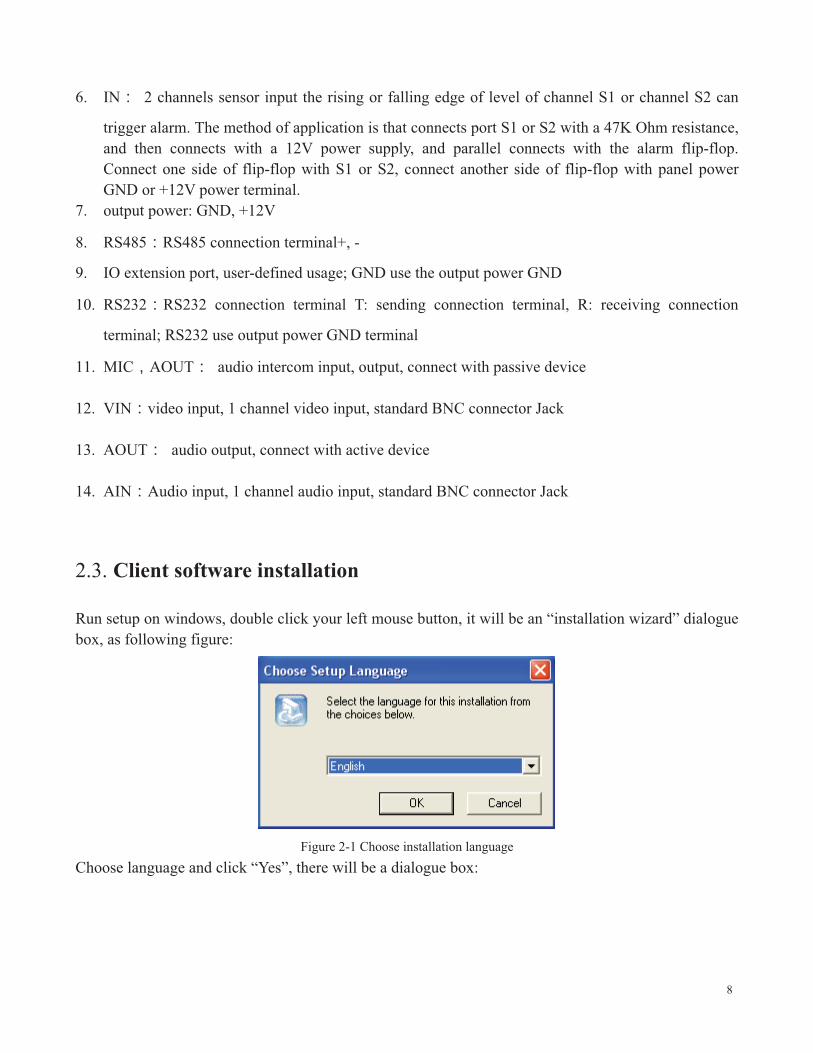
Figure 2-4 Choose installation folder
Choose installation folder, click “next”, there will be a dialogue box:
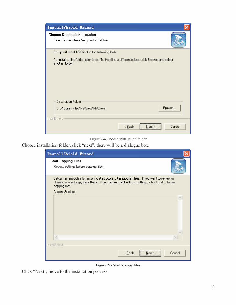
Figure 2-5 Start to copy files
Click “Next”, move to the installation process
11
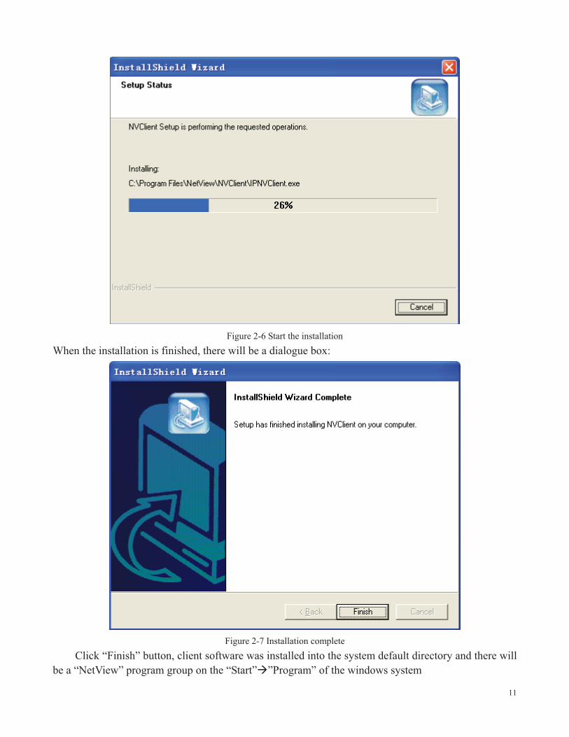
Figure 2-6 Start the installation When the installation is finished, there will be a dialogue box:
Figure 2-7 Installation complete
Click “Finish” button, client software was installed into the system default directory and there will be a “NetView” program group on the “Start”�”Program” of the windows system

12
3. Video server parameter configuration
There are following types of NVS-6000 video server parameter configuration:
1) Set DVS parameter via client software (connect DVS with computer via network)
2 Set DVS parameter via IE (connect DVS with computer via network)
NVS-6000 video server supports network preview, parameter setting and remote control via software and IE Use setting tool
When you login the server successfully with IE, you can use the convenient setting tool provided by us to configure the video server. Click “parameter setting” with left mouse button, configuration tool will pop-up a new page, displayed as following:
Figure 3-1 Server setting

13
3.1. Video and image setting
Notice When setting the video and picture's parameters of the 2 or 4 channels device, it will restart
automatically. Video and image setting interface is displayed as following:
Figure 3-2 Channel setting
3.1.1.Video attribute setting
Video attribute setting includes video mode, color and definition setting
� Video Mode Video Mode includes PAL and NTSC standard, each channel can choose different
system(please note that the 4-channel server can only choose a same system for each channel)
� Color Setup Color Setup includes the brightness, contrast and hue. The left of the setting bar is
the minimum value, you can easily drag the bar control to change value by mouse. For fine tuning you can use the direction key of keyboard.

14
� Definition Definition includes a 4-level definition setting of video. The left of the setting bar is
the minimum value, you can easily drag the bar control to change value by mouse. For fine tuning you can use the direction key of keyboard.
3.1.2. Image setting
Image setting includes the Video Format (image resolution), Encode Audio, Frame Rate, I Frame interval, maximum quantification coefficient, minimum quantification coefficient, and bit rate settings. (Details are described in the next part “Advanced image setting skill”)
� Video Format Image setting. It is adjusting the resolution, please refer to the table:
resolution PAL system NTSC system D1(4CIF) 720*576 720*480
HD1(2CIF) 720*288 720*240 CIF 352*288 352*240
QCIF 176*144 176*120
Notice: 1-channel products or 2-channel products support D1 (4CIF) resolution. 4-channel series products support CIF resolution.
� Encode Audio Select the encoding audio item of check box if you need audio. Uncheck the
encoding audio item if you only need video.
� Frame Rate It means how many frames the encoder is encoding per second. For details please
refer to table 1.
� I Frame Inv It means the number of frame P or frame B between key frames (frame I)
� Rate Type When the VBR(Variable Bit rate) is chose, the video server will automatically
choose a proper stream according to the complex and movement condition of images and the image quality is set by user, but the “stream rate” will not exceed. When the CBR (Constant Bit rate) is chose, the video server will control the “stream rate” in the setting.
� Image Quality Image quality. It is an important parameter which controls image quality; it can
be set in 5 levels. For setting please refer to “Advanced image setting skill”

15
� Bit Rate “Bit Rate” means the amount of stream bit encoding by encoder in a second, the unit
of stream rate is bps, namely bits per second. The range of stream rate is from 16k to 4096k, please note that the unit k means 1000, for example 4096k means 4096000bps, the encoder will use 4096000bps stream rate to encode video.
For more details of setting of the above part please refer to the following “Advanced image setting skill”
3.1.3.Advanced image setting skill
Image setting is an important part in the server setting because it will affect the system ability, it has close relationship with the video quality and network ability. The aim of image setting is to make it conveniently suitable for various networks. Bit stream and frame rate settings are providing in system, but it is hard to suit various networks with only several default values. Consequently, some advanced settings are provided for user to ensure the video quality while utilizing network effectively.
The image settings including Bit Rate , Frame Rate , I Frame Inv , Rate type , Image
Quality and Definition are what we concern about.
Now we will introduce meaning, effect to other settings and network ability of each setting respectively.
� Bit Rate
It means the size of stream bit encoding by encoder per second. The unit is bit per second. This setting is the main factor affects the bandwidth of network and other settings. The bandwidth utilizing will increase when the bit rate increase. Thus CBR (Constant Bit rate) setting according to the bandwidth is suitable for the network bandwidth limitation situations. In the same quality situation, bit rate will be affected by settings including frame rate, I frame Inv, rate type, image quality, and definition. Please refer to following introduction for details. This parameter is valid when the “Rate Type” is set as CBR (Constant Bit rate).
� Frame Rate
It means the maximum number of frames that encoder encodes per second, with unit frame per second. this setting has three functions, firstly the number of frames encoder encoding per second is set by this setting, secondly when the stream rate is CBR (Constant Bit rate), when the frame rate changed, for example decreased, because the encoder need to keep the current code stream setting, thus it will enhance the frame quality according to the current code stream setting. It means, when the code stream is VBR (Variable Bit rate), the decreasing of frame rate will enhance the quality of video and keep the same frame rate value. The video quality will reduce conversely. Thirdly, when the same quality is kept,

16
the increasing frame rate will make the image display smoother and stream rate increasing. Conversely, the image will become discontinuous and stream rate decrease.
� I Frame Inv
It means the number of frame P or frame B between key frames (frame I). Generally, the default value of this parameter is 25 and does not need to be changed. When the stream rate is settled, the increasing of this value will make the quality of video better. When the video keep the same quality, this value increasing will make stream rate increased. Conversely, the stream rate will decrease.
� Rate Type
when the VBR(Variable Bit rate) is chose, the front end will automatically choose a proper stream according to the complex and movement condition of images and the image quality set by user, but the “Bit Rate” will not exceed. When the CBR (Constant Bit rate) is chose, the front end will control the “Bit Rate” in the setting.
� Image Quality
It is an important parameter which controls image quality; this parameter is valid when the “Rate Type” is set as VBR (Variable Bit rate).
� Definition
Definition controls the sharpness of image, setting with 4 levels: 1 for lowest, 4 for highest. When the video keep the same quality, the higher the definition is, the higher the stream rate will be, conversely, the stream rate will decrease. When the stream rate is constant as a low value, the higher the definition is, the lower the image quality will be. When the stream rate is a high value, the higher the definition is, the better the image quality will be.
To sum up, please refer to our reference value for various conditions and the information giving above to adjust the image setting. You can make adjusting according to the above description if the quality of video is not satisfied.
reference setting attribute frame
rate rate type image quality Bit rate resolution
CBR(Constant Bit rate)
CBR(Constant Bit rate) 25 CBR(Constant
Bit rate) invalid set according condition
set according condition
LAN VBR(Variable Bit rate) 25 VBR(Variable
Bit rate) best unlimited set
according condition
ADSL- upload 512k
CBR(Constant Bit rate) 12 CBR(Constant
Bit rate) invalid 384k D1
ADSL-upload CBR(Constant 12 CBR(Constant invalid 512k D1

17
1M Bit rate) Bit rate) ADSL-upload
2M CBR(Constant
Bit rate) 25 CBR(Constant Bit rate) invalid 768k D1
best VBR(Variable Bit rate) 25 VBR(Variable
Bit rate) best unlimited set according condition
good VBR(Variable Bit rate) 25 VBR(Variable
Bit rate) good unlimited set according condition
normal VBR(Variable Bit rate) 25 VBR(Variable
Bit rate) normal unlimited set according condition
bad VBR(Variable Bit rate) 25 VBR(Variable
Bit rate) bad set according condition
set according condition
worst VBR(Variable Bit rate) 25 VBR(Variable
Bit rate) worst set according condition
set according condition
user-defined user-defined
Notice: pleas slightly adjust values referring to above reference values according to the system condition. You can make necessary adjusting according to the description of each setting if you have strict requirements for the image quality or the bandwidth.
3.2. OSD/MASK setting
The “OSD setting” shown as following figure includes the OSD/MASK setting. In the setting “ ”
in “ ” means enabling the corresponding overlay option function, contrarily disabling the
corresponding function.

18
Figure 3-3 OSD setting
� Display information setting This setting achieves the characters overlay function, including
date overlay, time overlay, channel description overlay, and font display. Date and time will be displayed on the top left of the preview image. Channel description displays the location with coordinate X (0~720) and Y(0~576)
� Mask zone setting This setting achieves the video mask setting function on specific zone.
Click “Covering” by left mouse button, a setting dialogue box will pop-up. Then draw a zone where you would like to mask on the image with left mouse button and click “Ok”, the setting is finished. If you would like to cancel the mask setting, click “Clear” with left key and click “Ok” directly.

19
Figure 3-4 Video Mask zone setting
3.3. Audio setting
The setting of audio is in the “Camera Setup” page. Clicking “ ” on “ ”in the “Encode Audio”
means the system will encode audio and send encoded audio stream to the client via network.

20
Figure 3-5 Audio setting
3.4. System network setting
The setting is shown as following figure:
21
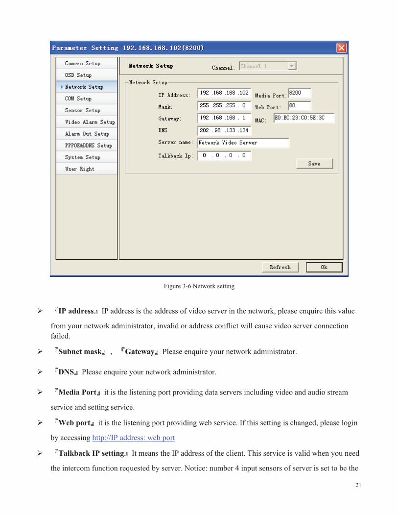
Figure 3-6 Network setting
� IP address IP address is the address of video server in the network, please enquire this value
from your network administrator, invalid or address conflict will cause video server connection failed.
� Subnet mask Gateway Please enquire your network administrator.
� DNS Please enquire your network administrator.
� Media Port it is the listening port providing data servers including video and audio stream
service and setting service.
� Web port it is the listening port providing web service. If this setting is changed, please login
by accessing http://IP address: web port
� Talkback IP setting It means the IP address of the client. This service is valid when you need
the intercom function requested by server. Notice: number 4 input sensors of server is set to be the

22
intercom request button. You need to set the IP before you start an intercom from the server. After this IP setting server will request an intercom to this IP (the machine with this IP must run our client software firstly), the intercom will start if the client agree, and otherwise the intercom will be failed.
� Current server name setting This setting can help you easy remembering the server. For
example, you can set a name “369 Nan Shan Rd.” for a server located at 369 Nan Shan Rd.
� Save Click this button when you finished corresponding setting options.
3.5. PTZ, COM setting
3.5.1.PTZ device management
All of our servers support 64 types of common PTZ protocols. Servers use transparent transmission method to manage PTZ device. 12V power supply is provided by server for dome, plus RS 485 connection. The server can configure PTZ device remote parameter setting including baud rate, stop bit, parity bit etc. and dome speed remote control via network.
3.5.2.PTZ protocol setting
The PTZ protocol setting is shown as following figure:

23
Figure 3-7 COM setting
� PTZ proto Choose the protocol from the pull-down menu, server supports 64 types of common
protocols. You can upload your protocol if the protocol you need is not in the pull-down menu. Server supports transparent transmission, please contact us for further information about self-defined PTZ protocol.
� Address Input the address of your PTZ, generally the address is configurable.
� Speed You can set the running speed of the dome here.
� COM parameter You need to select the COM parameter between the device and the dome
from the pull-down menu to ensure the communication.
� Save Click this button when you finished corresponding setting options. Then you can
conveniently control PTZ through our control tool.

24
3.5.3.RS232 serial port parameter setting
Server supports RS232 serial port transparent transmission function, data can be transmitted from client to server via network, server send the data to the serial port.
3.5.4.PTZ management FAQ
1 Can not control dome, the possible reasons include: hardware errors for example PTZ power supply
is not connected, RS485 cable connection is not correct. Check if PTZ protocol is properly set. PTZ protocol, address, and baud rate must correspond with the dome which is using. Then check if the control speed value is set as 0. if these operations can not solve problems, please contact our technical support department.
2 Please contact our engineer to upgrade the protocol, if your protocol is a private protocol.
3.6. Alarm and event management
This section describes the video server alarm parameter setting and the responding when video servers received an alarm
Alarm type Combined action Trigger event Alarm Attribute
Video motion alarm
can combine camera output
1. Images capture and upload to client, 2. auto call the speed dome to the appointed presetting
client configurable and save in log
automatic after setting
Sensor input alarm
can combine camera output
1. Images capture and upload to client, 2. auto call the speed dome to the appointed presetting
client configurable and save in log
automatic after setting
Video loss alarm
can combine camera output
1. Images capture and upload to client
client configurable and save in log
automatic after setting
Sensor output -------- trigger alarm device --------- automatic or manual after setting
Table 7

25
3.6.1.Video motion alarm management
After the video motion alarm function is enabled, when there are motions in the image at specific time and district, the video server will perform alarm operation such as JPG image capture or sensor output combination and send alarm message to client according to the action setting. Client will deal with the alarm according to the local setting. Video motion alarm information including server name, IP, alarm type, and time will be saved into log for future inquiry. The setting can be set as triggering server automatically login and image opening by client, if the client has not connect with network dome when an alarm happened.
Motion alarm setting instruction
It is shown as following figure
Figure 3-8 Video motion detection setting In the “Video Alarm” setting, choose “Video Motion” for the “Alarm Type” selection, shown as
above figure.

26
� Enable Auto Snapshot When the motion events happened, system will send alarm JPG image
to all connected clients automatically.
� Alarm Time Set For specific time that motion events need to be detected, input the time setting
value according to your conditions.
� Linkage Alarm Out System provides 2 channels on-off camera outputs for user to connect
with bells, lights, beepers etc. When motion event happens, system will output on-off value to attached devices.
� Alarm Clear Time alarm cancellation time. The alarm output will be canceled after this time
� Alarm area To set the image dynamic detection zone (each channel of image is divided into a
matrix with 9 rows and 11 lines. There are 99 zones can be set), zones out of set zones will not perform the dynamic detection task. Red zones mean “they are image dynamic detection zones”. You can draw the zones with mouse.
� Sensitive The sensitivity of motion detection, 1 is the highest value.
Setting skill
1 You can set the detection sensitivity as a higher value to avoid the false alarm causing by small
object motions.
2 You can set sensitivity as a higher value to avoid the frequent alarm at environment where object
motions frequently happen.
3 Only extreme accurate motion alarm settings need lower sensitivity value. High sensitivity value is
recommended for all other situations.
3.6.2.Video loss alarm management
After the video loss alarm function is enabled, when the video loss happened, the video server will perform the sensor combined output operation and send alarm message to client. Client will deal with the alarm according to the local setting. Video loss alarm information including server name, IP, alarm type, and time will be saved into log for future inquiry.
Video loss alarm setting It is shown as following figure:

27
Figure 3-9 Video loss alarm setting
� Alarm Time Set Input value to detect loss events in specific time according to real conditions.
� Linkage Alarm Out System provides 2 channels on-off camera outputs for user to connect
with bells, lights, beepers etc. When video loss event happens, system will output on-off level to attached devices.
� Alarm Clear Time The alarm output will be canceled after this time.
3.6.3.Sensor input management
After the sensor alarm service is enabled, when the sensor input alarm happened, video server will perform following actions:
Combine the preset sensor to output
Capture JPG images and upload them to client

28
Call preset of dome automatically
Send alarm information to client or trigger the unconnected client connection and video
opening Sensor alarm setting
It is shown as following figure:
Figure 3-10 Sensor input alarm setting
� Sensor Name The description of a sensor for easy remembering, for example “entrance”,
“switch room”
� Alarm Time Set Input value to detect sensor trigger events in specific time according to real
conditions.
� Alarm Duration The sensor output will be canceled after this time

29
� Enable Alarm Snapshot When the sensor trigger events happened, system will send alarm
JPG image to specific client automatically. The client must be specified firstly and set its IP address in “network setting”
� Preset channel When the sensor is triggered, system will automatically preset dome as the
“PTZ preset position”, system must connect with a preset-supporting dome and set preset position on the main interface.
� Output Set System provides 2 channels on-off value for user to connect with bells, lights,
beepers etc. When sensor trigger event happens, system will output on-off value to attached devices.
3.6.4.Sensor output setting
The function of alarm output can automatically trigger specific sensor output on-off value to trigger alarm devices such as beepers. The setting is shown as following figure:
Figure 3-11 Camera output alarm setting

30
3.7. PPPOE&DDNS setting
If the server is using dial up Internet connection please set the PPPOE and DDNS here.
Figure 3-12 PPPOE&DDNS setting
3.8. Center platform connection setting
Platform connection setting is the necessary setting of the platform surveillance for the front end device, please see the following figure:

31
Enable Register on “Center”: front end will automatically register the IP address the system assigned. Disable the item if the device does not connect with platform.
Center IP: the IP address of the center platform server. Center port: the network port of the platform server.
3.9. System setting
This section introduced system common settings including system time, system parameter saving, system upgrade, system version, system restart, and system factory settings restore, shown as following figure:

32
Figure 3-13 System setting
� Server Time Set System provides remote video server and client time calibration function.
Confirm the client device’s time and then click “set” to synchronize the time of server.
� Save Click “save” to save the parameter into flash of the server, unless system will use the
previous settings after the restart.
� Server Upgrade Please do not use this function except professionals. Click “browse” button to
choose the upgrade file, as following figure:

33
Figure 3-14 Choose upgrade file

34
Figure 3-15 Choose upgrade file
Then click “Upgrade”, click “Ok” button in a pop-up box.
Figure 3-16 Start to upgrade
The system will start the upgrade process. A progress bar will show the real time upgrade progress.

35
Figure 3-17 Upgrading
When the upgrade finished, there will be a status bar showing “Update success. The server will restart”. After the restart you can check if the system is the same version as your upgrade package.

36
Figure 3-18 Upgrade successfully
� Restore Restore all parameters with factory settings except network settings and password.
� Restart Click “Restart” button, the server will restart.
3.10. User rights setting
The server supports maximum 5 users. Each user has independent rights. You can authorize rights to a
user with clicking the “ ” on the “ ”. The details are introduced following:

37
Figure 3-19 User right setting
� Enable User Clicking “ ” on “ ” means enable this user. Only enabled user can login the
server, otherwise the login will be forbade.
4. Client software operation
4.1. System login, lock and logout
4.1.1.System login
In Windows operation system, run “NVClient” in “start”�”program”�”NetView” menu, the user login window will pop up

38
Figure 4-1 Login
Input username, password as above figure: username and password are not necessary as default value
Figure 4-2 Input username and password
Click “Login” to enter the main menu

39
Figure 4-3 Main menu Main menu consists of network preview, function button, servers list and status display.
4.1.2.System lock
Click button in main menu, the client window will be locked and can not continue any
operation. Re-click system lock button, a dialogue box will pop up:
Figure 4-4 Unlock dialogue box

40
Input username and password in the dialogue box and click ok to unlock the system.
4.1.3.System logout
Click button in main menu, a dialogue box will pop up:
Figure 4-5 Logout input dialogue box Input username and password and click ok to logout system.
4.2. System setting
4.2.1.Server management
Server management will add a server into the local client servers list.
Click button in main menu and then a local setting window will pop up. Enter the normal setting attribute page, as the figure:

41
Figure 4-6 Server management
Add server:
42
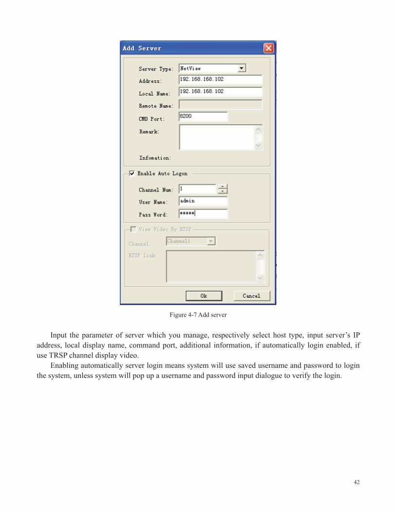
Figure 4-7 Add server
Input the parameter of server which you manage, respectively select host type, input server’s IP address, local display name, command port, additional information, if automatically login enabled, if use TRSP channel display video.
Enabling automatically server login means system will use saved username and password to login the system, unless system will pop up a username and password input dialogue to verify the login.

43
Figure 4-8 login the server
Figure 4-9 Input the server’s parameters The factory settings’ username and password are admin and admin. Thus in this example we use
admin, admin to login. Click “Ok” button to complete the adding process, the added servers list can be viewed in the following figure:

44
Figure 4-10 Video server adding completed
Server modification: select server from servers list and click the modify button or double click a
server to modify the attribute of a server. A window similar as the server adding window will pop up:

45
Figure 4-11modify server
Delete the server. Select a server from the servers list and click the delete button to delete an added server. For example, in the above figure, delete the 102 serve. When the delete process completed, the system will delete the server in the main menu.

46
Figure 4-12 the result of 102 server deleting
4.2.2.User management
Click the button in the main menu to pop up a local setting window and enter the normal setting attribute page, please refer to the figure:
47
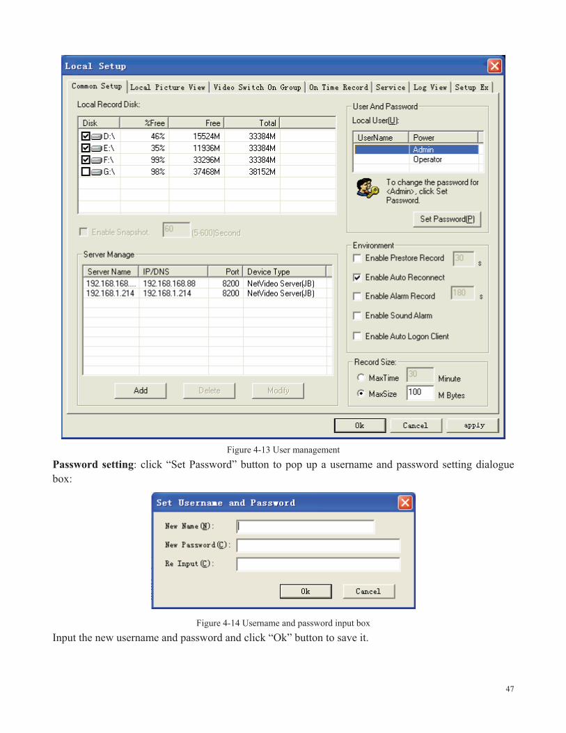
Figure 4-13 User management
Password setting: click “Set Password” button to pop up a username and password setting dialogue box:
Figure 4-14 Username and password input box Input the new username and password and click “Ok” button to save it.
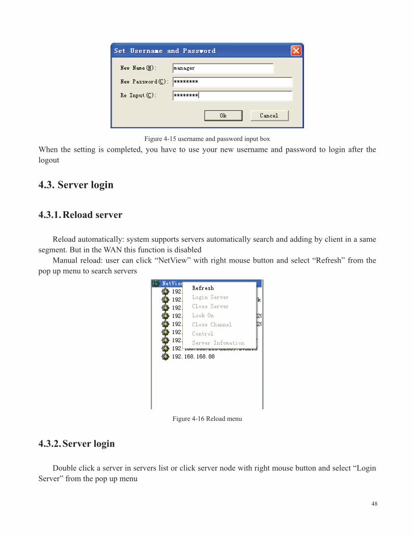
48
Figure 4-15 username and password input box When the setting is completed, you have to use your new username and password to login after the logout
4.3. Server login
4.3.1.Reload server
Reload automatically: system supports servers automatically search and adding by client in a same segment. But in the WAN this function is disabled
Manual reload: user can click “NetView” with right mouse button and select “Refresh” from the pop up menu to search servers
Figure 4-16 Reload menu
4.3.2.Server login
Double click a server in servers list or click server node with right mouse button and select “Login Server” from the pop up menu

49
Figure 4-17 Server login menu
Input username and password in the pop up dialogue box and click connect.
Figure 4-18 Login dialogue box
4.3.3.Server logout
Click server node with right mouse button and select “Close Server” from the pop up menu

50
Figure 4-19 Server logout menu
4.4. Video browse and control
The system can provide professional real time surveillance function, hundreds node management, 64 image surveillance at one time supporting, multi image cyclic switch, front user grouping management supporting, and grouping switch.
4.4.1.Video browse
Open a video: double click channel in the server list or click channel with right mouse button and select “Open Channel”, shown as following figure:

51
Figure 4-20 Video channel open menu Close the video:
Method 1: double click the opened video channel in the servers list to close the video. Method 2: click a video image with right mouse button and select “Close Channel” from the pop up menu as following figure:
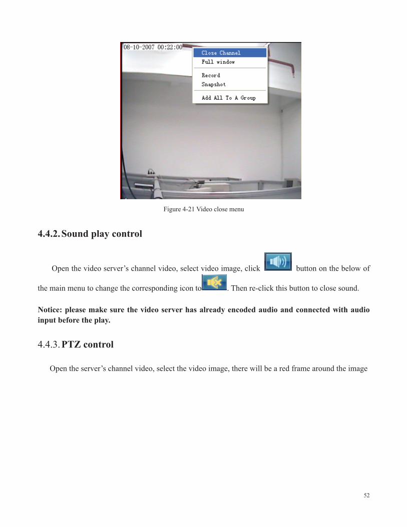
52
Figure 4-21 Video close menu
4.4.2.Sound play control
Open the video server’s channel video, select video image, click button on the below of
the main menu to change the corresponding icon to . Then re-click this button to close sound. Notice: please make sure the video server has already encoded audio and connected with audio input before the play.
4.4.3.PTZ control
Open the server’s channel video, select the video image, there will be a red frame around the image

53
Figure 4-22 Image selection menu Control button to control the PTZ
Notice: please check the PTZ setting errors and PTZ device errors if the control failed.
Figure 4-23 PTZ control menu
4.4.4.Preset position
Open the video server’s channel video and select video image.

54
Add preset position: preset PTZ to a position and input number in the preset position input box, click “preset” button to complete the setting. Input number in the preset position input box, click “call” to preset the camera.
Figure 4-24 Preset control menu
4.5. Audio intercom
This function achieves the audio intercom function between client personnel and video server watcher. The intercom can be requested from both sides. Client side supports audio broadcast enabling intercom with more than two servers.
4.5.1.Client request intercom
Click button in the main menu, an audio intercom dialogue box will pop up as following figure:

55
Figure 4-25 Audio intercom window
4.6. Video grouping, viewing
4.6.1.Video grouping setting
Click the button in main menu, in the pop up local setting menu, click “grouping switch” page, as figure:

56
Figure 4-26 Video grouping setting menu
Add a group In the “video grouping setting menu”, click “Add” button to pop up the following dialogue box. Input the group name and click “Ok”.
Figure 4-27 Input group name The group “102” you added will be displayed in the group name list

57
Figure 4-28 Add completely menu
For each image channel setting in group “102”: after selecting “102”, select an image from the “Channel Setup” list and click the “Set” button or double click, there will be a pop up dialogue box:
Figure 4-29 Server selection
Select the server and channel which you want to display and click “Ok”, please see the following figure Notice: The server list only displays servers which were added and launched the automatic login setting. For the setting method please refer to “Server Management”

58
Figure 4-30 Server and channel selection
Figure 4-31 A image setting completed
Follow the above steps to configure the video channel of image display server, add multi groups, the result will be:

59
Figure 4-32 Setting completed menu
4.6.2.Video grouping view
Click the in main menu to pop up a configured group list, as figure:

60
Figure 4-33 Video group view Select a group and open the video of this group
4.6.3.Video grouping cyclic switch
“Video grouping cyclic switch” means cyclic displaying video of each configured video group
according to the time interval. Click button in main menu to start the cyclic switch. Re-click
button if you need to stop the cyclic switch.
4.7. Image capture
The mechanism of image capture is image capture by front-side and uploading to client. Thus the high definition D1 image can be captured although real time browse is CIF image.

61
4.7.1.Capture setting
Storage path setting:
Click button in main menu to pop up the local setting menu. Enter the “Common Setup” attribute page; choose the storage disk in the “Local Record Disk”, as following figure: Notice: system will save files to hard driver D with folders named “NVFile” if there is not storage selection.
Figure 4-34 Storage path setting
4.7.2.Manual capture
Users can manually capture images while they are viewing video.

62
Method 1: Select the “capture” item from the pop up menu by clicking open video image with the right mouse button.
Figure 4-35 Manual capture menu
Method 2: Select open video image with left mouse button, and then click button in main menu with left mouse button. Method 3: Select open video image with left mouse button, and then use shortcut key “F6”.
4.7.3.Alarm capture
Front-side alarm automatically capture and image uploading to client to save.
4.7.4.Capture images browse
Click button in main menu to pop up the local setting menu, enter the “Local Picture View” attribute page to view images

63
Figure 4-36 Images view
4.8. Video record
The system supports 7*24 hours record, manual record, alarm record, pre-record, local/remote record search, and record cover automatically.
4.8.1.Record setting
Setting path:
Click button in main menu to pop up the local setting menu, enter the “Common Setup” attribute page, and choose the storage hard driver in the “Local Record Disk”.

64
Figure 4-37 Path setting
Startup pre-record: startup pre-record and set pre-record time in the “Environment” item. Set the record file packing size.
Figure 4-38 Record packing
4.8.2.Timer record
Click button in main menu to pop up the local setting menu, enter the “On Time Recode” attribute page as following figure:

65
Figure 4-39 Timer record time interval setting
Notice:
1 For enabling timer record function, the video server must enable automatically login
server function firstly, please refer to “server management” for details
2 Please do not close video when you enable the timer record, otherwise the system will not
record automatically. The client must logouts and re-logins to restore the timer record.
4.8.3.Manual record
Start record: Method 1: select “Record” item from the pop up menu by clicking video image with right mouse
button, as the figure:
66
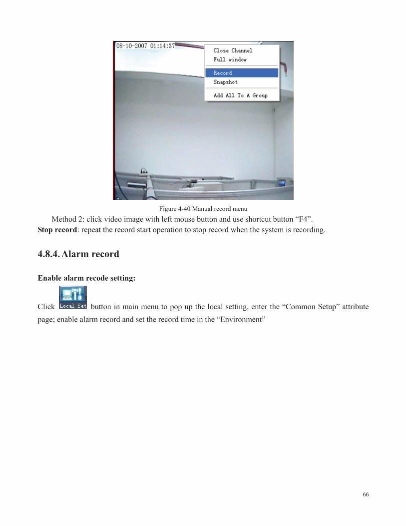
Figure 4-40 Manual record menu
Method 2: click video image with left mouse button and use shortcut button “F4”. Stop record: repeat the record start operation to stop record when the system is recording.
4.8.4.Alarm record
Enable alarm recode setting:
Click button in main menu to pop up the local setting, enter the “Common Setup” attribute page; enable alarm record and set the record time in the “Environment”

67
Figure 4-41 Enable record setting
Enable combined alarm record: Enable server video motion combined record, as following figure:

68
Figure 4-42 Video detecting alarm combined record setting
Enable server camera alarm combined record, see the figure:

69
Figure 4-43 Sensor alarm combined record setting
Enable server video loss combined record, see figure:

70
Figure 4-44 Video loss alarm combined record setting
Click “More Info” button to display all combined record settings
4.8.5.Record status checking
Method 1: timer record setting: click button in main menu to pup up the local setting menu, enter the “On Time Record” attribute page to check if status displaying “Running”, if yes it means it is recording currently, as the figure:

71
Figure 4-45 Timer record status display
Method 2: open the video of the server video channel, it means it is recording if there is an icon
on the image.

72
Figure 4-46 Record status display
4.8.6.Video data search
Video data search will search the path of the driver according to the storage settings.
4.9. Alarm management
Alarm management includes:
1 Enable corresponding channel record
2 Enable local sound alarm
3 Automatically channel pop up
4 Alarm information display
4.9.1.Alarm management setting
Enable “Enable Sound Alarm”

73
Figure 4-47 Local sound alarm
Set alarm sound output file Set alarm automatically pop up channel Set pop up electronic map Set alarm pop up information
74
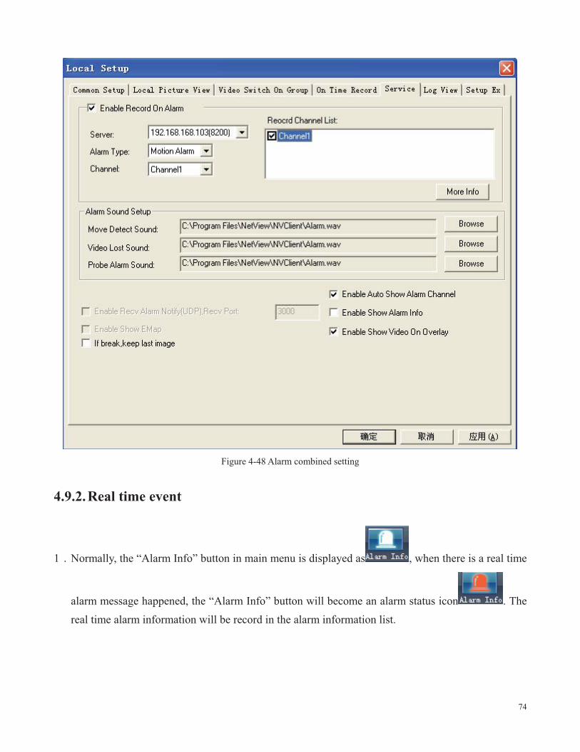
Figure 4-48 Alarm combined setting
4.9.2.Real time event
1 Normally, the “Alarm Info” button in main menu is displayed as , when there is a real time
alarm message happened, the “Alarm Info” button will become an alarm status icon . The real time alarm information will be record in the alarm information list.

75
Figure 4-49 Real time event display
2 There will be an icon in the corresponding video window when a video channel alarm happens
Figure 4-50 Video alarm display

76
4.9.3.History event
5. Frequent problems
If you have problems in using, please refer to following steps to check and solve them Check hardware and interface Please check you power supply firstly, and then check if your network is connected, lastly check if your cables are well connected. If there is not any problem with them please see if the lights are flashing properly on the front panel referring to table 3. Continue to next step if all of the following checking items are well.
1 Upgrade software
Check if the software is the latest version according to the “advanced setting” section. Upgrade it if not. Generally the latest version software will solve some problems and will be more stable than the old version software.
2 Contact technical support
Please contact technical support or browse our website for technical consultation if the problem is still exists.
3 Frequent problems solutions
a can not visit video server via browser
a) Possible reason: network disconnected
Solution: Connect network with PC to check if the network is connected well. Firstly check cable failure and network problems caused by virus, until the network is connected successfully by checking with ping command
b) Possible reason: IP address conflict
Solution: Disconnect the server’s network and connect server with PC to reset IP address according recommended operations
c) Possible reason: IP address in different subnets
Solution: Check the IP address and subnet mask of server and gateway
d) Possible reason: web port is changed
77
Solution: Contact network administrator to obtain corresponding port information
e) Possible reason: unknown
Solution: Reset server to the factory settings and re-connect network. The default IP address of system is 192.168.55.78
b can not control dome
f) Possible reason: signal cable is not connected or not connected properly
Solution: Re-connect control cable with dome and server
c can not view normal image
g) Possible reason: OS is Win98
Solution: Install DirectX8.0 or later version
d can not use Media player to play the record file
Solution: Download and install divx common decoder.

78
6. Appendix � specs
Codec MPEG4 H.264 Resolutions
FULL- D1 PAL:720*576, NTSC:720*480
CIF PAL:352*288, NTSC:352*240
QCIF PAL:176*144, NTSC:176*120
HALF-D1 PAL:720*288, NTSC:720*240
FULL- D1 PAL:704*576, NTSC:704*480
CIF PAL:352*288, NTSC:352*240
QCIF PAL:176*144, NTSC:176*120
HALF-D1 PAL:704*288, NTSC:704*240
Video in 1~4 channel NTSC PAL auto detect
BNC level 1.0Vp-p impedance 75Ω
1~4 channel NTSC PAL auto detect
BNC level 1.0Vp-p impedance 75Ω
Frame rate PAL 25F/S NTSC 30F/S
Bit stream type Video stream or complex stream Bit rate
16K 4M bps
Audio in 1channel BNC line in impedance 600Ω 4 channel BNC line in impedance 600Ω
Audio out mic/BNC interface Audio codec ADPCM G.711

Audio sample 8Kbps 16Kbps Audio intercom input
Mic
Network interface
One RS232 Serial interface One RS485 Serial interface
Alarm input 2 channel Alarm output 2 channel Power supply DC 12V Powerconsumption
Less than 3.5W
Working temperature
-10 -- 50
Working humidity
10 --90

80
7. Appendix factors influencing system capability
You must consider the whole system capability issue and factors influencing your system and system optimized settings when you set up your system. Bandwidth including stream rate setting, frame rate, and too many client connections influencing frame rate is the main issue that we need to consider. Following are the common factors which will influence the server efficiency that we need to consider:
1 Firstly is your bandwidth. Generally on LAN the bandwidth is not a problem but we must
consider the upload bandwidth on WAN or some private networks. If the upload bandwidth is 513k or lower, you would better set the output stream of server within 512k, otherwise the video or audio may play discontinuously.
2 We must emphasize the ADSL. Usually we are considering the download bandwidth of
ADSL, but for the video server application, we are using its upload bandwidth. Thus at this point we have to concern about the upload bandwidth for the system design, for example, for an ADSL with 1.5M download bandwidth, the upload bandwidth is less than 512k. Thus the upload bandwidth is what we have to concern about mostly for the network design.
3 About the image parameter setting according to networks please refer to “image advanced
setting” in “image setting”
4 Too many clients viewing from a video server will influence the server capability and
cause the frame reducing. Consequently, we recommend that the maximum viewing connections is 20.
5 Capture function provided by video server is using the front-side high definition image
capture method. Frequent captures will influence the server capability and cause frame rate reducing.
6 Network overload will influence the system capability and cause the audio and video
playing discontinuously.
7 CPU capability insufficiency will cause the audio and video playing discontinuously.
8 Wireless transmission will cause the disconnection and server re-connection from client
due to the unstable of wireless network.