Guide to tinplate
124
138 Guide to Tinplate
-
Upload
tony-wallace -
Category
Technology
-
view
2.493 -
download
34
description
Guide to Tinplate Published in 2000
Transcript of Guide to tinplate
138
Guide to Tinplate

133
ITRI Ltd
ITRI Ltd is the world’s foremost authority on tin and its applications and isrecognised by the UK government as a Scientific Research Organisation. ITRI issponsored by the world-wide tin industry, both miners and smelters, to supportand expand the use of tin metal, through continuous improvement of thetechnological processes involved in its applications, the development of newuses and promotion through conferences, seminars etc. ITRI research is ongoingin the following main areas:
Tinplate packaging
Tin alloy coatings
Solder technology
Chemical applications
Environmentally driven projects
137
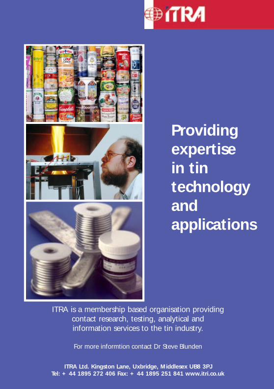
ITRA is a membership based organisation providingcontact research, testing, analytical andinformation services to the tin industry.
For more informtion contact Dr Steve Blunden
ITRA Ltd. Kingston Lane, Uxbridge, Middlesex UB8 3PJTel: + 44 1895 272 406 Fax: + 44 1895 251 841 www.itri.co.uk
Providingexpertisein tintechnologyandapplications

134
ITRA Ltd (Tinplate Panel)
ITRA Ltd is a membership-based organisation, established in 1993, to servicethe needs of the tin consuming industries. Member companies have access tothe services and expertise of ITRI, as well as the results of its chemical andmetallurgical R & D programmes. In addition, Industry Group Panels devoted toeither tinplate packaging, chemical applications or solder technology (Soldertec),
provide a forum for discussion and collaboration.
The ITRA Tinplate Panel aims to help the tinplate industry maintain and developits market share through technical support and collaboration, and represents allsegments of the tinplate packaging industry (tinplate producers, electrolytesuppliers, can makers, lacquer manufacturers etc), throughout all regions of theworld. Collaborative programmes cover such topics as:
Lacquer performance
Corrosion resistance
Can decoration / product differentiation
Environmental issues
Full details of membership of the ITRA Ltd Tinplate Panel may be obtainedfrom:
ITRA Ltd (Tinplate Panel)Kingston LaneUxbridgeMiddlesexUB8 3PJUKTel: +44 (0) 1895 272406Fax: +44 (0) 1895 251841
Copyright © 2000 ITRA Ltd.
Printed in the UK
Published by ITRA Ltd.,Kingston Lane, Uxbridge, Middlesex, UB8 3PJ, United Kingdom.
135
ACKNOWLEDGEMENTS
This 2nd Edition of the Guide to Tinplate was prepared using contributions writtenby technical experts from companies and organisations involved in the tinplatepackaging industry, all of whom are members of the ITRA Ltd, Tinplate Panel.
The following are therefore gratefully acknowledged:
Corus (UK & Netherlands)
Crown Cork & Seal (UK)
ICI Packaging Coatings (UK)
Lawson Mardon Can (UK)
National Steel (USA)
PPG Packaging Coatings (UK)
Rasselstein Hoesch (Germany)
Shipley Ronal (USA)
Usinor (Belgium)
VAI Industries (UK) Ltd
The Association of European Producers of Steel for Packaging (APEAL), Belgiumare also thanked and in particular Mr. Bev Page (Consultant) is thanked for hiscontributions and editorial review.

136
Acknowledgements to Figures
Figures 2, 4, 5, 7, 9, VAI (UK) Ltd.
Figures 3, 6, Rasselstein Hoesch GmbH.
Figure 8, Blaw-Knox Co., Aetna-Standard Div.
Figure 10, The Head Wrightson Machine Co. Ltd.
Figure 11, “From The Making, Shaping and Treating of Steel, © Association ofIron Steel Engineers, with permission”.
Figure 17, 18, Continental Can European Industries SA.
Figures, 19, 20, 22, Crown Cork & Seal Company, Inc.
Figure 21, Krupp Kunststofftechnik GmbH.
Figures 23, 24, 25, The Association of European Producers of Steel for Packaging(APEAL).
Cover photograph by kind permission of
Rasselstein Hoesch GmbH
1
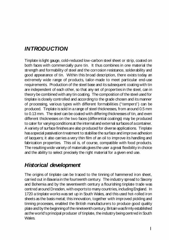
INTRODUCTION
Tinplate is light gauge, cold-reduced low-carbon steel sheet or strip, coated onboth faces with commercially pure tin. It thus combines in one material thestrength and formability of steel and the corrosion resistance, solderability andgood appearance of tin. Within this broad description, there exists today anextremely wide range of products, tailor-made to meet particular end-userequirements. Production of the steel base and its subsequent coating with tinare independent of each other, so that any set of properties in the steel, can intheory be combined with any tin coating. The composition of the steel used fortinplate is closely controlled and according to the grade chosen and its mannerof processing, various types with different formabilities (“tempers”) can beproduced. Tinplate is sold in a range of steel thicknesses, from around 0.5 mmto 0.13 mm. The steel can be coated with differing thicknesses of tin, and evendifferent thicknesses on the two faces (differential coatings) may be producedto cater for varying conditions at the internal and external surfaces of a container.A variety of surface finishes are also produced for diverse applications. Tinplatehas a special passivation treatment to stabilise the surface and improve adhesionof lacquers; it also carries a very thin film of an oil to improve its handling andfabrication properties. This oil is, of course, compatible with food products.The resulting wide variety of materials gives the user a great flexibility in choiceand the ability to select precisely the right material for a given end use.
Historical development
The origins of tinplate can be traced to the tinning of hammered iron sheet,carried out in Bavaria in the fourteenth century. The industry spread to Saxonyand Bohemia and by the seventeenth century a flourishing tinplate trade wascentred around Dresden, with exports to many countries, including England. In1720 a tinplate works was set up in South Wales, and this used hot-rolled ironsheets as the basis metal; this innovation, together with improved pickling andtinning processes, enabled the British manufacturers to produce good qualityplate and by the beginning of the nineteenth century, Britain was firmly establishedas the world’s principal producer of tinplate, the industry being centred in SouthWales.

2
The substitution of steel for iron as basis metal, together with the advent ofmechanical tinning machines, lessened the dependence on cheap labour andincreased productivity. After 1891 the U.S. domestic industry got under wayand by the beginning of the twentieth century, United States production wassufficient to meet the demands of the home market. In the first half of thepresent century, the most significant developments were in the productionmethods of the steel base, in particular the continuous rolling of steel strip. Hotdipped tinplate, however, was still tinned on a sheet-by-sheet basis. The nextmajor development in the tinplate industry was the introduction of electrotinning.An experimental electrotinning plant had been constructed in Germany as earlyas 1915, but it was not until the 1930s that cold-rolled steel strip was beingelectrotinned on a commercial scale, initially in Germany. World War II, whentin supplies became short, provided the impetus for the widespread developmentof the electrotinning process, with its possibilities for more economical tincoatings. The first commercial plant in the U.S.A. was put into operation in1943; within five years, half of United States tinplate output was being producedelectrolytically.
The trend to the replacement of hot-dipping tinplate units by continuouselectrolytic lines continued steadily throughout the world over the next thirtyyears. Further technical developments, such as continuous annealing and “doublereduction” of the cold-rolled steel strip before tinning, together with the use ofdifferential coatings aided the remarkable expansion of the industry during thisperiod. By the 1980s over 13 million tonnes of tinplate were being producedeach year, and manufacture had spread to some 37 countries.
Although the principal application is in packaging, tinplate also has a considerablediversity of minor uses. These include light engineering applications, domesticappliances and toys.
Tinplate is a veryimportant outlet for tinsince it represents about30% of total tinconsumption. Todaythere are manyalternative materials inthe packaging market,particularly aluminiumand PET. There has beena trend towards the useof thinner tin coatingsand lighter yet equallystrong steel substrates.
Figure 1One of the earliest tinplate manufacturing plants.
3
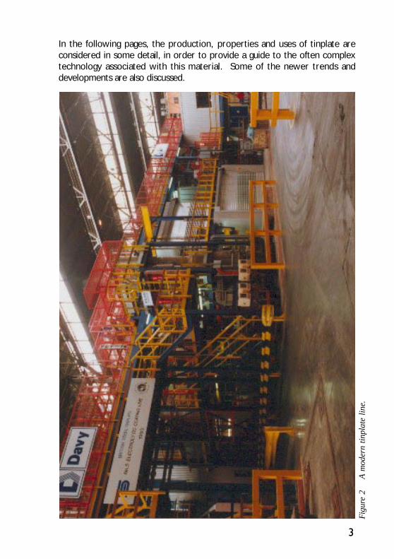
In the following pages, the production, properties and uses of tinplate areconsidered in some detail, in order to provide a guide to the often complextechnology associated with this material. Some of the newer trends anddevelopments are also discussed.
Fig
ure
2A
mod
ern
tinpl
ate
line
.
5
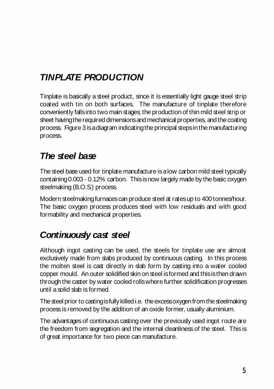
TINPLATE PRODUCTION
Tinplate is basically a steel product, since it is essentially light gauge steel stripcoated with tin on both surfaces. The manufacture of tinplate thereforeconveniently falls into two main stages; the production of thin mild steel strip orsheet having the required dimensions and mechanical properties, and the coatingprocess. Figure 3 is a diagram indicating the principal steps in the manufacturingprocess.
The steel base
The steel base used for tinplate manufacture is a low carbon mild steel typicallycontaining 0.003 - 0.12% carbon. This is now largely made by the basic oxygensteelmaking (B.O.S.) process.
Modern steelmaking furnaces can produce steel at rates up to 400 tonnes/hour.The basic oxygen process produces steel with low residuals and with goodformability and mechanical properties.
Continuously cast steel
Although ingot casting can be used, the steels for tinplate use are almostexclusively made from slabs produced by continuous casting. In this processthe molten steel is cast directly in slab form by casting into a water cooledcopper mould. An outer solidified skin on steel is formed and this is then drawnthrough the caster by water cooled rolls where further solidification progressesuntil a solid slab is formed.
The steel prior to casting is fully killed i.e. the excess oxygen from the steelmakingprocess is removed by the addition of an oxide former, usually aluminium.
The advantages of continuous casting over the previously used ingot route arethe freedom from segregation and the internal cleanliness of the steel. This isof great importance for two piece can manufacture.

6
Figure 3 Principal steps in the manufacturing process
Hot rolled stripPickling
Batch Annealing
Continuous AnnealingCold rolling
Warehouse
LaminatingSlitting
Shearing Printing, Lacquering
Temper rolling
Cleaning
Tinning/Chromium Coating

7
Hot rolling
Continuous casting machines deliver slabs directly to the Hot Mill ready forsubsequent hot rolling. The finished slabs may be up to 1300mm wide x 250mmthick. They may be scarfed prior to hot rolling to remove surface defects whichcould have a harmful effect on subsequent processing.
The slabs are reheated to a soak temperature of between 1200 to 1300°C.The slabs are then hot rolled firstly through a roughing section where the slab isreduced from the initial 250mm to 35 - 45mm in thickness and then rolledthrough the finishing section where the final gauge is achieved. Coils for tinplateusage usually have a final gauge somewhere between 1.6mm - 3.0mm.
The roughing section may comprise four or five four-high non-reversing standsor a single four-high reversing mill, dependent on the mill design. The finishingtrain may have up to seven four-high rolling stands in tandem, (see Figure 4).
After rolling, the strip is cooled to a controlled temperature on a run out tableusing banks of water sprays. The strip is then coiled ready for further processing.
Control of the slab heating and the roughing, finishing and coiling temperaturesis critical for obtaining the required mechanical properties. In a moderncontinuous hot strip mill the exit speed may be up to 16m/s.
During cooling the steel surface develops an oxide scale and this must beremoved prior to subsequent cold rolling. Removal of the oxide is carried outby an acid treatment in a pickling line. The coil is fed into the pickling line via a“scalebreaker” which mechanically flexes the strip around the rollers and loosensbrittle scale. This process is made continuous by welding the coils together atthe entry end to the line.
The pickle line proper consists of a hot water preheat tank, acid pickling tanks(normally four), primary and secondary spray rinse tanks and a hot water diptank. The tanks are enclosed to extract fumes. The pickling acid is 20% sulphuricacid at 900C or 10% hydrochloric acid at room temperature. Sulphuric acidhas been traditionally used but there is a trend towards using hydrochloric acidwhich is quicker acting and gives a clean white surface after pickling.
In order to minimise attack on the steel itself inhibitors are usually included inthe pickling solutions. Drag out between tanks is usually prevented by sets ofwipers and wringer rolls.
At the exit of the line the strip edges can be trimmed if required and oil isapplied to both surfaces prior to recoiling. The oil acts as a protection againstcorrosion during storage and as an initial lubricant in the subsequent coldrolling operation.

8
Cold reduction
All modern tinplate has a cold reduced steel base and almost all is rolled in amulti-stand mill. Most operators use a five-stand, four-high tandem mill forcold rolling, although there are some six- and four-stand mills, (see Figure 5).The feedstock for the cold reduction mill is the pickled and oiled hot rolled coiland normally individual coils are rolled separately. About 90% cold reduction isimparted. For conventional tinplate, as opposed to double-reduced, the steelis rolled roughly to the final ordered thickness in this cold rolling stage.
Modern cold reduction mills operate at speeds up to 2400 m/min. Many factorssuch as load, inter-stand tension, lubrication, cooling and roll contour are closelymonitored and controlled in order to produce a high yield of prime product.Most producers have installed automatic control equipment.
Cleaning
For cold reduction, lubrication is necessary and lubricating oil and water areapplied to the strip and rolls either separately or as an emulsion. All traces ofthis lubricant must be removed from the strip before annealing, since residualoil can cause staining or discoloration of the strip, preventing good tinning.Material destined for batch annealing is treated in a cleaning line in which thestrip passes through dip or spray tanks, followed by rinsing and scrubbing, thenonto an electrolytic treatment section. The solutions used in strip cleaning linesare usually made up from proprietary mixtures containing alkaline phosphatesor silicates together with sodium hydroxide and wetting agents. Finally thestrip is rinsed and dried in a blast of hot air. Fume extraction facilities are essential.In the case of steel destined for continuous strand annealing a cleaning section isincorporated in the annealing line.
Annealing
The mechanical working which the steel undergoes during cold rolling has aprofound effect on the mechanical properties. In cold working, the grainstructure is distorted and the metal becomes harder and stronger but less ductile.In order to soften the steel and restore its ductility, recrystallisation of the grainsis required. This can be induced by a controlled heat treatment cycle (processannealing) to produce the required grain structure.
Two types of annealing may be used in tinplate manufacture, batch (or box)annealing (BA) or continuous annealing (CA). By suitably selecting the steelgrade and the annealing cycle, batch annealing can produce steel having

9
Figure 4 Typical hot strip finishing train
properties ranging from deep drawing quality to hard, stiff material suitable toresist pressure or vacuum on can ends. Continuous annealing, by the virtue ofthe shorter annealing times, produces material with a finer grain size than BA.Therefore the mechanical properties differ for the same Temper number. SeveralCA qualities can be produced which cover the range of tinplate applications.
In batch annealing, tightly wound coils of cold rolled steel are stacked three orfour high on bases with convector spacers between coils. A cover is loweredonto the stack and is sealed at the base (see Figure 6). The atmospheresurrounding the coils is purged and replaced with slightly reducing atmosphere.A movable furnace is placed over the entire charge and the coils are heated to

10
Figure 5 General view of five-stand tandem mill.

11
the “soaking” temperature, which depends on the steel grade to be made, asdoes the soak time. After the period at temperature, the furnace cover isremoved and the charge is allowed to cool in a controlled manner. A typicalbatch cycle can range from 10 to 30 hours depending on the steel grade required.
A continuous annealing line (CAL) is divided into three parts, an entry sectionfor strip cleaning, a furnace section and an exit section. Modern continuous andprocess lines (CAPL), see Figures 7 and 8, have a section between the furnaceand exit section known as the overage section.
The cleaning section contains dip and spray tanks, followed by electrolyticcleaning. The furnace section is split up into a heating section, a soak sectionand a fast and slow cool section. In each section, a slightly reducing atmosphereis maintained and the strip makes a number of vertical passes through the fullheight of the furnace. The temperature cycle comprises heating rapidly toabout 680°C, holding at temperature for 20-25 seconds, controlled cooling to
Figure 6 General view of a batch annealing installation.

12
Figure 7 Continuous annealing line

13
480°C and then rapid cooling to roomtemperature. This cycle is for a CAL; forthe CAPL the strip is cooled to anoverage temperature of between 370 to400°C and held to allow carbon toprecipitate out of solution. It is cooledto near room temperature. Theprecipitation out of carbon softens thesteel and makes it more ductile for two-piece can manufacture.
To allow the process to be continuous,looping towers or accumulators arefound at the entry and exit end. Thesetowers contain sufficient metal to allowwelding up of coils at the entry end andcropping to length at the exit end.
Temper rolling
After annealing, the steel strip is in a verysoft condition and it is given a very lightrolling treatment, usually in a two-standmill operated without strip lubrication.This is known as “temper rolling” or “skinpass rolling” This process defines the finalgauge and imparts mechanical propertiesappropriate to the end use. It alsoimproves the strip shape and producesthe desired surface finish on the strip.The overall reduction is of the order of0.5 to 4%.
Temper rolling also removes thepronounced yield point noted on CAproducts. This allows ends and bodiesto be produced without “Luders” lines/bands being visible
Figure 8Schematic diagram of a typical line forcontinuous annealing of tinplate strip.EN
TRY
SEC
TIO
NW
ELD
ER
CLE
ANIN
G -
SCRU
BBIN
G &
RIN
SE S
ECTI
ON
ENTR
YAC
CU
MU
LATO
R
REC
OIL
SEC
TIO
N
EXIT
ACC
UM
ULA
TOR
FUR
NAC
E

14
Double reduction
Large quantities of relatively strong tinplate are now manufactured world-wideby the technique of double reduction. Thinner yet stronger tinplate can beproduced, which allows for more efficient materials utilisation in can making.After an initial cold rolling and annealing, instead of temper rolling, the steel isgiven a second cold reduction, with lubrication, of about 10-50%. The workhardening effect gives the steel additional strength, whilst the strip retainssufficient ductility for it to be formed into can ends and bodies. Final thicknesscan be as low as 0.12mm, the typical range being 0.14 - 0.24mm.
A two-stand or three-stand mill may be used for double reduction. Somecompanies operate a dual purpose mill which can produce double-reducedmaterial and operate as a conventional temper mill.
Double-reduced steel exhibits very marked directional properties and the graindirection should always be indicated and taken into account during formingoperations with the final tinplate.
Coil preparation
Before entering the tinning line the strip may be edge trimmed and inspectedon a coil preparation line. A strip thickness gauge may also be installed and off-gauge or sub standard plate may be cut out. Coils of optimum weight areproduced by welding strip lengths together.
Electrolytic tinning
Tinplate is now virtually all produced by the electroplating of tin on to the steelbase in a continuous process. The major reasons why electrotinning of steelstrip superseded hot-dip tinning, were because it can give a very much higherdegree of thickness control, including different thicknesses on the two sides ofthe steel sheet, and much higher outputs of tinplate, at higher quality and lowermanufacturing cost. As plating technology and steel chemistry have improved,steel base and tin coating thickness have been gradually reduced, significantlylowering the cost of production; today a typical coating thickness is in the range0.1 to 1.5 microns depending on the end use.
The most widely used process is the Ferrostan process (the trade name of USSteel) and this currently accounts for some 70% of world manufacturing output.This general description of electrolytic tinning is based on the Ferrostan process,with differences in line layout for other process types being discussed later.

15
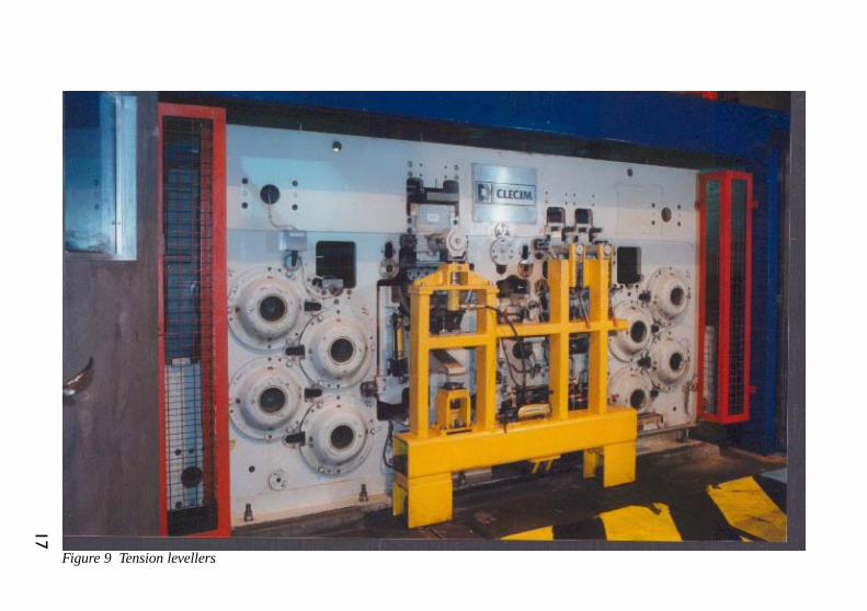
Blackplate coils weighing between 5 and 15 tonnes are fed onto the tinning line,being loaded onto the two uncoilers required to allow continuous operation.The tail end of the coil being processed is welded to the leading end of the nextcoil to be processed; this necessitates the two coils being stationary duringwelding. To avoid shut down during welding, lines are fitted with looping towersor accumulators that can hold varying amounts of uncoiled plate (often up to600 m). Most modern lines incorporate side trimmers after the accumulator tocut the strip to the correct width. Many lines now incorporate tension or stretchlevellers (Figure 9), which apply controlled tension across the strip to removedistortions.
Because cleaning times are very short i.e. 1 - 2 seconds, effective cleaningrequires the use of electrolysis to aid chemical dissolution of rolling oil residuesand other organic contaminants. Passage of heavy current produces gases atthe strip surface which undermine the soil and lift it from the strip. The cleaneris usually a 1-5 % solution in water of a mixture of phosphates, wetting agentsand emulsifiers in a sodium hydroxide / carbonate base. Temperatures arenormally 80-90°C with current densities of 10 A/dm2 usually adequate. Aftercleaning the strip is thoroughly washed, ideally in hot water (70°C) using high-pressure sprays.
Pickling removes oxide and rust layers and leaves the surface etched for betterdeposition of tin; during the process the strip is normally made anodic thencathodic with current densities between 5 and 30 A/dm2 being employed.
Various electrolytes can be used in the tinplating section and these are coveredmore fully later. The plating cells consist of a series of vertical tanks throughwhich the strip passes in serpentine fashion. The number of plating tank passesin use, the anode length and the strip width determine the effective platingarea. This, together with the available plating current, is mainly responsible forfixing the maximum line speed for any coating weight. Modern tinning linesachieve speeds of 600 m/min with reports of new lines being designed to runeven faster; typical strip widths are between 1 and 1.25 m. The steel strip isguided through the tanks by sink rolls located at the bottom of the tanks andconductor rollers with rubber covered hold-down rollers at the top; these collectelectrolyte from the strip and return it to the plating cell. The conductor rollsmust have good electrical conductivity and low contact resistance between theroll and the wet strip; they are normally made from steel coated with copperand then chromium.
Each plating tank has four anode bus bars and four banks of anodes, one foreach face of the down and up passes of the strip. Traditional anodes are madeof 99.9% pure tin and are 76 mm wide, 50 mm thick and about 1.8 m long.The anode is consumed in the process and is replaced when reduced in thickness
16
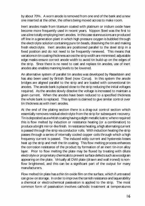
by about 70%. A worn anode is removed from one end of the bank and a newone inserted at the other, the others being moved across to make room.
Inert anodes made from titanium coated with platinum or iridium oxide havebecome more frequently used in recent years. Nippon Steel was the first touse a line totally employing inert anodes. In this case stannous ions are producedoff line in a generation plant in which high pressure oxygen is bubbled throughthe electrolyte solution containing pure tin beads, dissolving the tin and makingfresh electrolyte. Inert anodes are positioned parallel to the steel strip in afixed position and do not need to be frequently renewed. This means thatvariations in tin coating thickness across the strip width are minimised; adjustableedge masks ensure correct anode width to avoid tin build-up on the edges ofthe strip. Since there is no need to cast and replace tin anodes, use of inertanodes also enables manning levels to be lowered.
An alternative system of parallel tin anodes was developed by Rasselstein andhas also been used by British Steel (now Corus). In this system the anodebridges are aligned parallel to the strip and are loaded with conventional tinanodes. The anode bank is placed close to the strip reducing the initial voltagesrequired. As the anodes slowly dissolve the voltage is increased to maintain agiven current. When the anodes have been reduced to a specified thicknessthe whole bank is replaced. This system is claimed to give similar control overtin thickness as with inert anodes.
At the end of the plating section there is a drag-out control section whichessentially removes residual electrolyte from the strip for subsequent recovery.Tin is deposited as a whitish coating having a slight metallic lustre; where requiredthis is flow melted by induction or resistance heating (or a combination) toproduce a bright mirror-like finish. In resistance heating, a high alternating currentis passed through the strip via conductor rolls. With induction heating the strippasses through a series of internally cooled copper coils through which a highfrequency current is passed. The induced eddy current and hysteresis lossesheat up the strip and melt the tin coating. This flow melting process enhancesthe corrosion resistance of the product by formation of an inert tin-iron alloylayer. Prior to flow melting the plate may be fluxed by treating with diluteelectrolyte or proprietary chemicals to prevent surface defects such as woodgrainappearing on the plate. Virtually all DWI plate (drawn and wall ironed) is non-flow brightened, and this can be a significant part of the output for manymanufacturers.
Flow melted tin plate has a thin tin oxide film on the surface, which if untreatedcan grow on storage. In order to improve the tarnish resistance and laquerabilitya chemical or electrochemical passivation is applied to the strip. The mostcommon form of passivation involves cathodic treatment at temperatures
17
Figure 9 Tension levellers

18
between 50 and 85°C in dichromate or chromic acid solution containing 20 g/ldichromate (other treatments which are now seldom used included use ofphosphates or carbonates). This treatment deposits a complex layer ofchromium and its hydrated oxides, which inhibits the growth of tin oxides,preventing yellowing, improving paint adhesion and minimising staining by sulphurcompounds. Prior to oiling the plate must be thoroughly dried. Oiling withdioctyl sebacate, or acetyl tributyl citrate is carried out in an electrostatic sprayprocess. Quality inspection is by in-line inspection prior to recoiling and involveschecking strip thickness, detection of pinholes and tin thickness.
Electrolyte types
Tin can be deposited from either stannous (Sn2+) or stannic (Sn4+) states. Virtuallyall lines now use acidic processes where tin is deposited from the stannousstate, the main advantages of this being that it only requires half the electricitycompared to deposition from the +4 oxidation state and since higher currentdensities are achievable fewer plating tanks are required.
Phenol sulphonic acid (PSA) electrolyte
The Ferrostan process, using PSA, was one of the first to be developed and hascontinued to dominate in most parts of the world. Figure 10 shows a flowdiagram of a typical line.
The electrolyte consists of a solution of PSA containing stannous ions plus additionagents which ensure good quality smooth deposits over a wide current densityrange. Over the years a variety of addition agents have been used includingsuch things as gelatine, dihydroxy diphenyl sulphone etc. Since the mid-1960’s,however, only two addition agents have been commonly used: ENSA-6,developed by US Steel and Diphone V, developed by Yorkshire Chemicals.
When making up a new electrolyte the tin is added as stannous sulphate; however,no further additions of this material should be required. Concentrations ofstannous tin below the recommended range of 25 - 35 g/l may result in highcurrent density defects such as dark deposits on unflowmelted plate and whiteedges. Free acid concentration is maintained by periodic additions of PSA. Lowacid levels reduce the conductivity of the bath and therefore require higheroperating voltages to pass the required current. Oxidation of tin (II) to tin (IV)occurs more rapidly at low acid levels increasing the amount of sludge. This isa waste of tin, since once tin (IV) has been formed it is no longer able to beplated out. On a typical well run line, tin lost as tin (IV) should be about 3 - 5 kgper 24 hours operation. If the addition agent concentration falls too low the

19
Fig
ure
10
Typic
al f
low
dia
gra
m f
or
a F
erro
stan e
lect
rotin
nin
g li
ne
plating range is reduced, thedeposit becomes less bright andin extreme cases adherence willbe poor; cathode efficienciesmay also be adversely affected.Typical operating conditions areline speeds of 300 - 500 m/min,current densities of 20 - 35 A/dm2 and temperatures of 40 -50°C. A considerable amount ofheat is generated by passage ofhigh currents and temperature iscontrolled by circulating theelectrolyte through a coolingsystem.
Halogen electrolyte
The second major electrolyteprocess in terms of worldproduction is the Halogenprocess, developed by E. I. duPont de Nemours, Weirton Steeland Wean Engineering. Thesystem operates on a differenttype of line to the Ferrostanprocess, with horizontal ratherthan vertical plating tanks. Thisconfiguration together with thehigh current densities used (65A/dm2), enables lines to be runfast, over 600 m/min beingcommon. The plating tanks areon two decks; each levelcontaining up to 18 plating tanks(1.8 m long by 300 mm deep)with banks of small anodessupported on conducting carbonrests, over which the strippasses. The anodes extendabout 130 mm beyond the stripedge and the supports arePA
Y-O
FF R
EELS
BRID
LE R
OLL
ENTR
Y LO
OP
TOW
ERAN
D S
TEER
ING
RO
LL
CLE
AN A
ND
PIC
KLE
TIN
NIN
G
BASE
MEN
T
ENTR
Y SE
CTIO
NPR
OCE
SS S
ECTI
ON
FLO
W B
RIG
HTE
NIN
G
CH
EMIC
AL T
REA
TMEN
T
EXIT
LO
OP
TOW
ER
ELEC
TRO
STAT
IC O
ILER
STEE
RIN
G R
OLL
EXIT
BR
IDLESN
IP S
HEA
R
TEN
SIO
N R
EELS
EXIT
SEC
TIO
N

20
inclined at an angle across the tank width which ensures constant spacingbetween strip and anode surfaces for anodes of progressively diminishingthickness. At the entry and exit of each plating level and between adjacentindividual plating cells the strip passes between a pair of rolls, the upperconducting roll being termed the cathode roll.
Tin is plated on the underside in the first deck. The steel is then turned through180° and enters the second deck where the other side is plated. The pH of thissystem (around 3) is high for an acid system, but no free acid is added to thebath. The bath contains tin chloride (around 35 g/l as Sn2+), sodium and potassiumfluorides, sodium chloride and potassium hydrogen fluoride together with organicadditives such as polyalkylene oxides or naphthalene sulphonic acid. Theelectrolyte continually circulates in the system, overflows the ends of the tanksand is recirculated. In the lower deck the electrolyte is sprayed onto the top ofthe strip to wet it.
After plating the strip passes through rinsing tanks, wringer rolls and a hot airdryer all located in a top third deck. In Halogen lines flow melting is usually byinduction heating.
Fluoroboric acid electrolyte
Fluoroborate systems were first used by Rasselstein in the late 1940’s, but havenever gained widespread use mainly due to commercial restrictions. Theelectrolyte contains tin fluoroborate (30 g/l as Sn2+), fluoroboric acid and boricacid to prevent hydrolysis of the fluoroborate ions: again proprietary additivesare employed. It is claimed that these lines can operate over a wider currentdensity range than Ferrostan systems allowing greater line flexibility.
Although the first lines to be built were horizontal, later lines are vertical,containing up to 16 plating tanks and running at line speeds of 640 m/min orhigher. Most of the other sections of the line are similar to those describedabove except that pickling is carried out with hydrochloric acid at roomtemperature without electric current.
Methane sulphonic acid (MSA) electrolyte
Methane sulphonic acid (MSA) based tin and tin alloy processes were firstdeveloped in the early 1980’s, and began to gain market acceptance in theelectroplating industry shortly thereafter. The advantages of these processesare claimed to include: high conductivity, biodegradability, low incidence ofstannic tin generation, wide current density range and adaptability of processattributes to end user requirements through the use of modern grain refiners.

21 Figure 11 Typical flow diagram of horizontal Halogen line
PLATING SECTION
REFLOW TOWER
OILING
CHEMICALTREATMENT EXIT SECTION
LOOPING TOWER
ENTRY SECTION LOOPING TOWER
CLEANING AND PICKLING SECTION

22
By the end of the decade, most tin alloy electrodeposits produced by theelectronics industry in Europe and the United States were from MSA basedprocesses, which had replaced the more traditional fluoborate electrolytes.
The success of MSA processes in the electronics industry led to furtherdevelopments for applications in heavy industry. In November, 1989, the firstcommercial tinplate production line using a patented MSA process (RonastanTP) developed by LeaRonal (now Shipley Ronal) began plating steel strip atHoogovens (now Corus), Ijmuiden, The Netherlands.
The MSA tinplate process has undergone several improvements in recent years,and has been installed in both vertical and horizontal cell tinplate lines, an attributeshared by no other tinplate electroplating process. Although the chemistry istailored to meet each individual line’s requirements, the general operatingconditions for the process are shown in Table 1.
Operating Parameter Vertical Cell
Operating Range
Horizontal Cell
Operating Range
Tin Concentration (g/l) 15 – 22 10 – 18
Free MSA (ml/l) 30 – 60 25 – 35
Primary Additive (ml/l) 40 – 60 40 – 60
Secondary Additive (ml/l) 1.8 - 3.2 1.8 - 2.8
Antioxidant (ml/l) 15 – 20 15 – 20
Temperature (°C) 30 – 50 30 – 65
PH 0 – 1 0 – 1
Current Density Range (ASD) 5 – 60 5 – 60
Table 1 MSA operating conditions
The above process does not contain any free phenol, cyanide, chloride, orfluoride compounds, nor any chelates. Simple neutralisation of plating batheffluent will produce tin hydroxides and sodium sulphate, and the filtered liquorcan be sent to sewer or river. Neutralised MSA has been reported to have alower toxicity than table salt.
Tin oxidation rates are slightly lower than those given by PSA processes, andare much less than those of the halogen processes. However, tin oxidationrates for the MSA process subjected to oxygen injection, such as is needed forthe Nippon Steel Tin Dissolution System, are significantly less than that of the

23
PSA processes, when iron contamination levels in these plating baths exceed 10g/l. The conductivity of MSA is approximately 30% higher than for PSA atequivalent acid strengths and temperatures. Operating advantages, such as higherproduction rates and prime yields have been reported by a number of tinplateproducers and these advantages have overcome the increased chemical costsof the MSA process.
The alkaline stannate electrolyte
Although still widely used for component tin plating this process is now virtuallyobsolete for plating of steel strip. Brief details are included here forcompleteness.
The main advantages of alkaline stannate processes are that the electrolyte isnon-corrosive to steel and that addition agents are not required to give a smoothgood quality deposit. However, these benefits are now seen to be outweighedby a number of disadvantages, the main one of which is that twice the theoreticalamount of electricity is required to deposit tin from the Sn4+ as from the Sn2+
state; this is obviously very costly. Other disadvantages include the loweroperable current density range and the lower efficiencies obtained. In alkalineelectrolytes at low current density, tin anodes would dissolve as stannite but ifthe current density is increased above a critical value, a film forms on the surfaceand tin then dissolves entirely as stannate. In practice, filming is achieved byraising the anode voltage for a few seconds at the outset.

25
BUYER’S GUIDE TO TINPLATE
In the production of tinplate, the manufacture of the steel base and the applicationof the tin coating are independent of each other so that theoretically any tincoating, or combination of coatings, may be applied to any steel base. Thus therange of materials classified as tinplate can run into many thousands, indeedtinplate is available in more qualities than virtually any other light gauge sheetmetal product.
In practice the range of steel base thickness is from 0.13 mm to 0.50 mm andthe tin coating from 0.5 g/m2 to 15.2 g/m2 tin per surface.
There are international and national standards which specify the ranges andtolerances for the various characteristics, and methods of verifying them. Theinformation in this chapter is based on the more widely used standards but forofficial requirements, readers are referred to the appropriate standardspecifications (tinplate standards are listed in the Appendix).
The steel base
The low carbon steel used for tinplate manufacture is produced and processedas outlined in Chapter II. The steel composition and its method of productionare normally matters for the producer, who should however, be given full detailsof the intended use, so that the optimum material can be supplied.
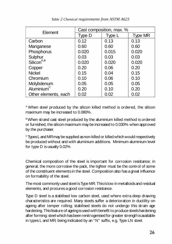
National and international specifications do not normally stipulate compositionrequirements. However, some standards such as ASTM A623 give a generalguide to the types of steel most generally used. Table 2 outlines the chemicalrequirements for three steel types. It should be noted that the percentagesquoted are maximal and normally the actual amounts are much lower, e.g. thecarbon is frequently well below 0.10%C. The generalisation of continuous castingrequires that steel formulation must be able to produce the highest steel qualities.All the tinplate produced in Europe is now “continuously cast”.
26
Table 2 Chemical requirements from ASTM A623
Cast composition, max. % Element
Type D Type L Type MR Carbon Manganese Phosphorus Sulphur SiliconA,B
Copper Nickel Chromium Molybdenum AluminiumC
Other elements, each
0.12 0.60 0.020 0.03 0.020 0.20 0.15 0.10 0.05 0.20 0.02
0.13 0.60 0.015 0.03 0.020 0.06 0.04 0.06 0.05 0.10 0.02
0.13 0.60 0.020 0.03 0.020 0.20 0.15 0.10 0.05 0.20 0.02
A When steel produced by the silicon killed method is ordered, the siliconmaximum may be increased to 0.080%.B When strand cast steel produced by the aluminium killed method is orderedor furnished, the silicon maximum may be increased to 0.030% when approvedby the purchaser.C Types L and MR may be supplied as non-killed or killed which would respectivelybe produced without and with aluminium additions. Minimum aluminium levelfor type D is usually 0.02%
Chemical composition of the steel is important for corrosion resistance; ingeneral, the more corrosive the pack, the tighter must be the control of someof the constituent elements in the steel. Composition also has a great influenceon formability of the steel.
The most commonly used steel is Type MR. This is low in metalloids and residualelements, and procures a good corrosion resistance.
Type D steel is a stabilised low carbon steel, used where extra deep drawingcharacteristics are required. Many steels suffer a deterioration in ductility onageing after temper rolling; stabilised steels do not undergo this strain agehardening. This feature of ageing is used with benefit to produce steels hardeningafter forming: steel which has been renitrogenised for greater strength is availablein types L and MR, being indicated by an “N” suffix, e.g. Type LN steel.

27
Thickness
The tin coating on tinplate is so thin that for practical purposes it can be ignoredin considering thickness, so that the specified thickness is essentially that of thesteel base. Conventional tinplate, as defined in international standards, falls withinthe range 0.15 mm to 0.49 mm; double reduced tinplate from 0.13 mm to 0.29mm. Lower gauges down to 0.08mm are now available for special uses, eitherin single- or double-reduced base materials. Heavier gauges of conventionaltinplate are available from a number of sources, up to 0.6 mm. However, insome cases, notably in the U.S.A. and Europe, material above 0.5 mm thick isdescribed as “tinned sheets”, rather than as “tinplate”.
Tinplate is today described principally in terms of metric dimensions, e.g. theSITA (System International Tinplate Area) which is 100 square metres. However,until a few years ago, the unit of trade was the basis box (base box in U.S.A.)and the nomenclature still persists within some parts of the industry.
The basis box is an area of sheet of 31,360 square inches (20.2325 m2). Itderives from the time when weighing was the accepted method ofmeasuring both sheet and coating thickness and corresponds to a unit of 112sheets each of the (then) standard size 20x14 in. The surface area of a basis boxis 62,720 in2.
Theoretical thickness Nominal weight Ib/base box In Mm 45 50 55 60 65 70 75 80 85 90 95 100 103 107 112 118 128 135 155 175 195 215 235 235
0.0050 0.0055 0.0061 0.0066 0.0072 0.0077 0.0083 0.0088 0.0094 0.0099 0.0105 0.0110 0.0113 0.0118 0.0123 0.0130 0.0141 0.0149 0.0170 0.0192 0.0214 0.0236 0.0258 0.0280
0.127 0.140 0.155 0.168 0.183 0.196 0.211 0.224 0.239 0.251 0.267 0.279 0.287 0.300 0.312 0.330 0.358 0.378 0.432 0.488 0.544 0.600 0.655 0.711
Table 3 Nominal base weight (substance)for tinplate
When tinplate is sold bythe basis box, thethickness is known as the“substance” or“baseweight”. It is definedin terms of poundsavoirdupois per basis box(lb/bb). Material sold interms of “substance”, or inImperial measurements, isnormally available in aspecified range ofthickness as shown inTable 3 which gives theinter-conversion betweenmetric thickness,fractional inch thicknessand substances expressedin Ib/bb.

28
Mechanical properties
Tinplate is available in a wide range of forming grades or “tempers”. Themechanical properties depend on a number of factors including steelcomposition, rolling practice, the annealing cycle and the degree of skin-pass,or temper rolling.
The term “temper” when applied to tinplate, summarises a combination ofinterrelated mechanical properties. There is no single mechanical test that canmeasure all the factors that contribute to the fabrication characteristics of thematerial. However, the Rockwell 30T Hardness Test is in general use as a quicktest which serves as a guide to the properties of the material. For single-reducedtinplate only the Rockwell superficial hardness test is at present specified.However, the determination of tensile strength of the product is a moretechnically sound and meaningful measure of the mechanical behaviour. Thistechnique is more and more practised and will become by 2001 the Euronormbase for material designation. For double-reduced tinplate the determinationof tensile properties is already used to determine mechanical properties. Themethods of carrying out these tests are described in Chapter VII together withother supplementary tests.
The Rockwell 30T values for tinplate form the basis for classifying tinplate intoa system of temper designations, as shown in Table 4. These cover the mostgenerally used designations.
Temper classification Yield /0.2% proof
Hardness
Current Future Former Rp (±50N/mm²)
HR30T(±4) Examples of uses
T50BA TS230 T1 230 <=52 Deep drawing T52BA TS245 T2 245 52 Drawing T55BA TS260 - 260 55 General purpose – Aerosol tops T57BA TS275 T3 275 57 General purpose – Aerosols bodies T59BA TS290 T4 290 59 General purpose T61CA TH415 T4 415 61 Crown corks + Ends T65CA TH435 T5 435 65 Ends & Bodies – Aerosols bottoms T70CA -- T6 530 70 (Non) easy open ends DR520CA TH520 -- 520 -- Ends DR550BA TS550 DR8 550 -- Bodies DR550CA TH550 DR8 550 -- Ends & Bodies DR580CA TH580 -- 580 -- Ends DR620CA TH620 DR9 620 -- Ends & DRD cans DR660CA -- DR9M 660 -- Ends
Particular national standards may have other temper designations. Currentpractice for single-reduced tinplate is to use the aim R30T value as theclassification and for double-reduced tinplate the tensile value. Formerly a simplenumerical grading from 1 to 9 was used.
Table 4 Tinplate temper designations

29
It should be noted that, primarily due to the differences in grain size and shape,the mechanical properties of batch annealed and continuously annealed materialof the same R30T value are not identical. A further point is that since the R30Ttest does not measure all the factors that contribute to the fabricationcharacteristics of tinplate, it is customary to specify the R30T value in terms ofan aim value or range rather than an exact value. The principal criterion foracceptance is that the tinplate should satisfactorily make the required part.Therefore the purchaser is advised to give the supplier full details of the part tobe made and of the method of fabrication. Similarly, any changes in these shouldbe discussed and recorded.
As described in Chapter II, double-reduced tinplate is manufactured by givingthe steel a second cold-reduction, of the order of 15 to 50%, following annealing.This operation replaces temper rolling. The resultant DR product is stiff andstrong; it also has marked directional properties, i.e. its formability is verydifferent in the rolling direction and transversely to it. For this reason, it isespecially important to specify the rolling direction and to use the DR tinplatecorrectly.
Surface finish
Single-reduced tinplate is available in a range of surface finishes. The practiceand new standards recognise five basic surface finishes, viz:
Bright finish - A surface provided by a flow-brightened tin coating on a smoothfinish steel base (steel roughness lower than 0.35µmRa).
Light stone finish - A surface provided by a flow-brightened tin coating on asteel base finish characterised by a light directional pattern (steel roughnessbetween 0.25 and 0.45µmRa).
Stone finish - A surface provided by a flow-brightened tin coating on a steelbase finish characterised by a directional pattern (steel roughness between 0.35and 0.60µmRa).
Matt finish – A surface provided by an un-melted coating generally on a shotblast finish steel base (steel roughness over 0.90µmRa).
Silver finish - A matt finish product that has been flow melted.
Double reduced tinplate is customarily supplied with a finish corresponding tostone-finish. It may however, also be available with an un-melted tin coating.
Certain manufacturers use a numerical system to classify the various surfacefinishes.

30
The tin coating
The tin used for the coating of tinplate has to be at least 99.85% pure. Thisdefines the tin used to make the anodes for electrolytic tinplate production (orthe grade of tin used to make up the baths in the hot dipping process).
In the US, ASTM B339-95, standard specification of pig tin, gives the compositionof Grade “A” tin for the manufacture of tinplate. The minimum tin concentrationis 99.85% and the maximum lead concentration is 0.010%.
Tin coating masses (formerly coating weight) are now customarily expressed ingrams per square metre of surface (g/m2.face).
Mention has been made of the older practice of expressing tinplate area interms of the basis box of 31,360 square inches of material. This system was alsoused to express tin coating masses. It is still widely used and understood andindeed the standard tin coating masses, which involve the use of decimal fractionsin the metric system, are based on whole numbers or exact fractions in termsof pounds per basis box (lb/bb). It should especially be noted that when tincoating masses are expressed in lb/bb they may relate to the total coating masson both surfaces, even in the case of equally coated electrolytic tinplate. In thecase of differentially coated tinplate (i.e. electrolytic tinplate with a differentcoating mass on each surface) the situation can be even more confusing. Originallythe coating mass (in lb/bb) referred to the equivalent coating on equally coatedtinplate; i.e. it represented the equivalent of double the coating for each surface.As an example, 1.00 lb/bb equally coated tinplate carries 0.5 Ib/bb (11.2 g/m2)per surface and 1.00/0.50 lb/bb differentially coated carries 0.50/0.25 lb/bb (11.2/5.6 g/ m2) per surface. More recently, (e.g. in ASTM A624) the nominal coatingin lb/bb is expressed per surface, although the designation number stillperpetuates the earlier system.
Nominal coating weight each surface Minimum average coating mass test value Designation No. Ib/base box g/m2 Ib/base box g/m2 10 25 35 50 50/25 75 75/25 100 100/25 100/50 135/25
0.05/0.05 0.125/0.125 0.175/0.175 0.25/0.25 0.25/0.125 0.375/0.375 0.375/0.125 0.50/0.50 0.50/0.125 0.50/0.25 0675/0.125
1.1/1.1 2.8/2.8 3.9/3.9 5.6/5.6 5.6/2.8 8.4/8.4 8.4/2.8 11.2/11.2 11.2/2.8 11.2/5.6 15.15/2.8
0.08 0.22 0.32 .047 0.47/0.22 0.70 0.70/0.22 0.90 0.90/0.22 0.90/0.47 1.25/0.22
1.8 4.9 7.2 10.5 10.5/4.9 15.7 15.7/4.9 20.2 20.2/4.9 20.2/10.5 28.0/4.9
Table 5 Tinplate coating masses expressed in lb/bb (from ASTM A624)
31
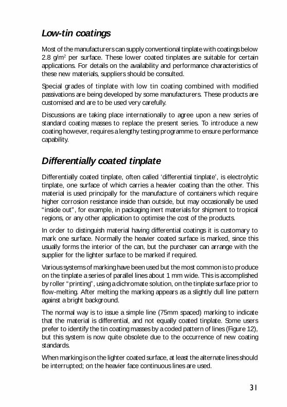
Low-tin coatings
Most of the manufacturers can supply conventional tinplate with coatings below2.8 g/m2 per surface. These lower coated tinplates are suitable for certainapplications. For details on the availability and performance characteristics ofthese new materials, suppliers should be consulted.
Special grades of tinplate with low tin coating combined with modifiedpassivations are being developed by some manufacturers. These products arecustomised and are to be used very carefully.
Discussions are taking place internationally to agree upon a new series ofstandard coating masses to replace the present series. To introduce a newcoating however, requires a lengthy testing programme to ensure performancecapability.
Differentially coated tinplate
Differentially coated tinplate, often called ‘differential tinplate’, is electrolytictinplate, one surface of which carries a heavier coating than the other. Thismaterial is used principally for the manufacture of containers which requirehigher corrosion resistance inside than outside, but may occasionally be used“inside out”, for example, in packaging inert materials for shipment to tropicalregions, or any other application to optimise the cost of the products.
In order to distinguish material having differential coatings it is customary tomark one surface. Normally the heavier coated surface is marked, since thisusually forms the interior of the can, but the purchaser can arrange with thesupplier for the lighter surface to be marked if required.
Various systems of marking have been used but the most common is to produceon the tinplate a series of parallel lines about 1 mm wide. This is accomplishedby roller “printing”, using a dichromate solution, on the tinplate surface prior toflow-melting. After melting the marking appears as a slightly dull line patternagainst a bright background.
The normal way is to issue a simple line (75mm spaced) marking to indicatethat the material is differential, and not equally coated tinplate. Some usersprefer to identify the tin coating masses by a coded pattern of lines (Figure 12),but this system is now quite obsolete due to the occurrence of new coatingstandards.
When marking is on the lighter coated surface, at least the alternate lines shouldbe interrupted; on the heavier face continuous lines are used.

32
It is extremely important for the purchaser to stipulate clearly to themanufacturer both the surface to be marked and the surface which is to bepiled uppermost (for sheets) or to be the exterior surface in material shipped incoil form. It is why the new European system identifies the marked face by theposition of the differential letter in the coating description:
D5.6/2.8 is : marking of the face coated with “5.6 g/m²”
5.6/2.8D is : marking of the face coated with “2.8 g/m²”
Inspection
Finished tinplates are inspected instrumentally and by visual examination.Inspection includes the detection of pin-holes, surface defects, blemishes,mechanical damage, and measurement of gauge, weight and dimensions.
Grades of tinplate
Electrolytic tinplate, standard grade: represents the normal production oflines employing the usual inspection and classification procedures. It permitslacquering and printing over the entire surface.
Electrolytic tinplate, second grade: is available in certain countries. Thisrepresents the best sheets rejected from the standard grade and may contain
Figure 12 Coding system for differentially coated tinplate
12.5
25
12.525
12.537.5
37.5
50
Coatingcodes
D5.6/2.8
D8.4/2.8
D11.2/2.8
D11.2/5.6
D15.1/2.8
D8.4/5.6
Marking line spaces in mm

33
sheets exhibiting surface imperfections, tinning defects and shape and otherminor defects. Second grade does not, however, include off-gauge material,nor sheets with pinholes.
There is no official third grade, but off-gauge and pinholed material may besuitable for some non-critical purposes and is sometimes sold as “wastecategory”.
National and international specifications prescribe a sampling scheme forassessing tinplate grades.
Passivation
A chemical or electrochemical passivation treatment is normally applied to thesurface of electrolytic tinplate. The principal purpose of the treatment is tostabilise the surface and thus to inhibit the growth of tin oxide on the surface.Excessive oxide can produce discoloration in prolonged storage and especiallyduring stoving operations associated with lacquering or printing.
The passivation treatment is applied to the strip in the electrolytic tinplate lineafter flow brightening and before oiling. The treatment consists of passing thestrip through an aqueous chemical solution, with or without applied current.
The most commonly applied treatment uses a sodium dichromate solution withapplied current, the strip being negative. An alternative treatment comprises asimple dip, without current, in a similar solution or in a chromic acid solution. Acathodic treatment in sodium carbonate solution is occasionally used when milkproducts are packed and there are other treatments which may be used fromtime to time, but are non standard and not available from every supplier.
Normally, unless otherwise agreed by the purchaser, the first of the abovetreatments, viz. cathodic sodium dichromate, is applied. Many tinplate producersadopt a numerical code to define passivation treatments. A typical system isone based on a three digit code. Where the first digit is used to indicate thesolution used (1 - chromic acid, 2 – chromate phosphate, 3 – sodium dichromate,4 – sodium carbonate.), the second digit refers to the polarity of the tinplate inthe solution (0 – non-electrolytic, 1 – cathodic, 2 – cathodic/anodic) and thethird digit refers loosely to the coulomb level employed.
Oiling
Electrolytic tinplate normally carries a very thin coating of oil, in order tofacilitate the separation of sheets or wraps of a coil. The oil must be of a type
34
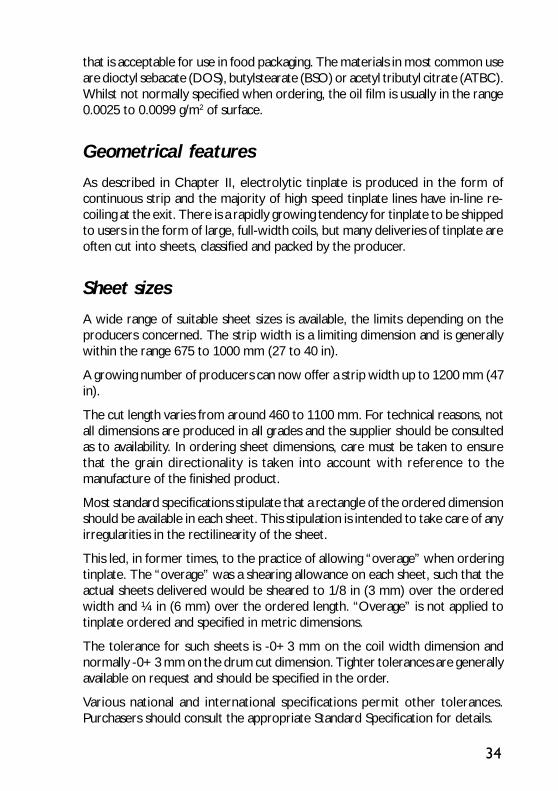
that is acceptable for use in food packaging. The materials in most common useare dioctyl sebacate (DOS), butylstearate (BSO) or acetyl tributyl citrate (ATBC).Whilst not normally specified when ordering, the oil film is usually in the range0.0025 to 0.0099 g/m2 of surface.
Geometrical features
As described in Chapter II, electrolytic tinplate is produced in the form ofcontinuous strip and the majority of high speed tinplate lines have in-line re-coiling at the exit. There is a rapidly growing tendency for tinplate to be shippedto users in the form of large, full-width coils, but many deliveries of tinplate areoften cut into sheets, classified and packed by the producer.
Sheet sizes
A wide range of suitable sheet sizes is available, the limits depending on theproducers concerned. The strip width is a limiting dimension and is generallywithin the range 675 to 1000 mm (27 to 40 in).
A growing number of producers can now offer a strip width up to 1200 mm (47in).
The cut length varies from around 460 to 1100 mm. For technical reasons, notall dimensions are produced in all grades and the supplier should be consultedas to availability. In ordering sheet dimensions, care must be taken to ensurethat the grain directionality is taken into account with reference to themanufacture of the finished product.
Most standard specifications stipulate that a rectangle of the ordered dimensionshould be available in each sheet. This stipulation is intended to take care of anyirregularities in the rectilinearity of the sheet.
This led, in former times, to the practice of allowing “overage” when orderingtinplate. The “overage” was a shearing allowance on each sheet, such that theactual sheets delivered would be sheared to 1/8 in (3 mm) over the orderedwidth and ¼ in (6 mm) over the ordered length. “Overage” is not applied totinplate ordered and specified in metric dimensions.
The tolerance for such sheets is -0+3 mm on the coil width dimension andnormally -0+3 mm on the drum cut dimension. Tighter tolerances are generallyavailable on request and should be specified in the order.
Various national and international specifications permit other tolerances.Purchasers should consult the appropriate Standard Specification for details.

35
Squareness and camber
The modern, high-speed machines used in manufacturing containers demandprecise sheet registration to ensure accuracy. Therefore, it is important to ensurerectilinearity of the tinplate sheets to within precise tolerance. Two parameters,which are customarily specified, are “out-of-squareness” and camber.
“Out-of-squareness” is defined as the deviation of an edge from a straight linedrawn at a right angle to the other edge of the sheet, touching one corner andextending to the opposite edge. It is normally expressed as a percentage
or as a maximum linear value for any edge measurement.
Camber is defined as the maximum deviation of a sheet edge from a straightline touching both corners and forming a chord to the edge. Camber is measuredin the plane of the sheet and is a measure of the straightness of the edge. Itshould not be confused with bow, which describes the flatness of the sheet.Camber may be expressed as a percentage
or as a maximum deviation for a given length of sheet edge.
Other sheet features
The sheets, when cut from the strip, have to lie flat. Several types of deviationfrom a perfectly plane surface are recognised, which may depend for their originon residual stresses in the sheet. They are described as follows:
Edge wave. This is an intermittent vertical displacement occurring at the sheetedge when the sheet is laid on a flat surface.
Centre buckle or full centre, is an intermittent vertical displacement or wavein the sheet occurring other than at the edges.
Longitudinal bow or line bow. This is the residual curvature in the sheetremaining along the direction of rolling.
larperpendicuoflength
deviation %100×
chordoflength
deviation %100×

36
Transverse bow or cross bow, is a mode of curvature in the sheet such thatthe distance between the edges parallel to the rolling direction is less than thesheet width.
There is another feature, which can arise when the strip is cut into sheets:
Burr. This can occur at the extreme edges of the sheet and is caused byshearing action. It is described as “metal displaced beyond the plane of thesurface of the sheet”.
Thickness variations
Whilst every endeavour is made to produce material of uniform cross-section,small variations occur in the thickness of the sheet, across the rolling width.
Crown is defined as the difference in thickness between the centre and edge ofthe strip. In practice, it is measured at the centre and at a point near the edges,but not within 10 mm of the edge. The thickness may be measured bymicrometer or by weighing samples cut from the sheet at appropriate locations.Usually the maximum deviation in thickness between centre and edge is specifiedas 5% of the average sheet thickness.
At the extreme edges of the rolled strip the thickness may be sharply reduced.This is known as “feather edge” or as “transverse thickness profile”. It is ofimportance to the canmaker, especially when using double-reduced tinplate.
Feather edge is defined as the reduction in sheet thickness at right angles tothe rolling direction, close to the edge. It is measured at a location 6 mm fromthe mill trimmed edge of the sheet. The usual tolerance permitted for thisextreme edge variation is a maximum of 6% compared to the actual centrethickness of the sheet being measured.
The thickness of tinplate may be determined by micrometer, but more usuallyin standards the thickness is calculated by weighing specimens statisticallysampled from a consignment at stipulated points.
The tolerance on thickness is specified in national and international standards.The actual value depends on the amount of material involved. For example, theinternational standard (ISO 11949) specifies for a single sheet a tolerance of+8.5% determined by weighing, whereas for a consignment the thicknesstolerance varies from +4% averaged over 20,000 sheets or less (15,000 m) or+2.5% averaged over a consignment in excess of 20,000 sheets (15,000 m).
Tighter tolerances, for specific end uses, may occasionally be negotiated betweensupplier and purchaser.
37
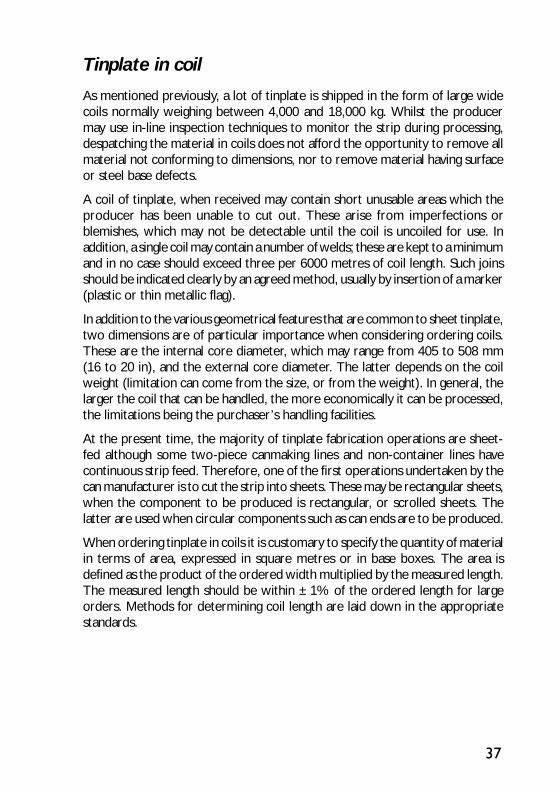
Tinplate in coil
As mentioned previously, a lot of tinplate is shipped in the form of large widecoils normally weighing between 4,000 and 18,000 kg. Whilst the producermay use in-line inspection techniques to monitor the strip during processing,despatching the material in coils does not afford the opportunity to remove allmaterial not conforming to dimensions, nor to remove material having surfaceor steel base defects.
A coil of tinplate, when received may contain short unusable areas which theproducer has been unable to cut out. These arise from imperfections orblemishes, which may not be detectable until the coil is uncoiled for use. Inaddition, a single coil may contain a number of welds; these are kept to a minimumand in no case should exceed three per 6000 metres of coil length. Such joinsshould be indicated clearly by an agreed method, usually by insertion of a marker(plastic or thin metallic flag).
In addition to the various geometrical features that are common to sheet tinplate,two dimensions are of particular importance when considering ordering coils.These are the internal core diameter, which may range from 405 to 508 mm(16 to 20 in), and the external core diameter. The latter depends on the coilweight (limitation can come from the size, or from the weight). In general, thelarger the coil that can be handled, the more economically it can be processed,the limitations being the purchaser’s handling facilities.
At the present time, the majority of tinplate fabrication operations are sheet-fed although some two-piece canmaking lines and non-container lines havecontinuous strip feed. Therefore, one of the first operations undertaken by thecan manufacturer is to cut the strip into sheets. These may be rectangular sheets,when the component to be produced is rectangular, or scrolled sheets. Thelatter are used when circular components such as can ends are to be produced.
When ordering tinplate in coils it is customary to specify the quantity of materialin terms of area, expressed in square metres or in base boxes. The area isdefined as the product of the ordered width multiplied by the measured length.The measured length should be within ±1% of the ordered length for largeorders. Methods for determining coil length are laid down in the appropriatestandards.
38
Packaging
Electrolytic tinplate shipped in sheet form is customarily packed on a woodenstillage platform forming a bulk package weighing between approximately 1,000and 2,000 kg. The number of sheets in each bulk package is usually a multiple of100.
Tinplate coils are usually packed on a platform to form a package weighingbetween 4,000 and 18,000 kg. The coils are normally despatched with the corevertical, unless otherwise requested.
The direction of the runners of the stillage platform is stipulated by the purchaser.
Various types of overwrap may be used, depending on the method of shipment,distance transported and climatic conditions. The outer wrap may be of stoutcardboard, or for arduous conditions, light gauge steel.
All packaging materials and constructional materials in stores should be dry andfree from volatile aggressive matter. Ventilation of stores, as a means of preventingcondensation, is also important. In transport, packages are completely sealedand enclose the minimum quantity of air. Sheets are packed in such a way thatvibration during transport is minimised, to prevent fretting corrosion, which islocal damage produced by very small relative movement of two metal surfacespressed into close contact with one another. Trucks, wagons and vessels usedfor transport are chosen with this in mind.
Each stillage or full width coil wrapping should contain a packing slip which fullyidentifies the material. Information should be provided on: customer, destination,sales order and item number, size, thickness, steel grade, surface finish andgrade and number of packages.
Ordering
It is recommended that consultations are held with the supplier before thepurchaser embarks on using a new product. The intended purpose should beclearly stated, together with details of the method of fabrication of the part.
Any subsequent modifications should also be discussed with the supplier; inturn, he should notify the user of any alterations in his practice which wouldsignificantly affect how the tinplate would be used.
The following factors may particularly need to be taken into account in ordering:
Form of tinplate: cut sheet, whole coil, or slit coil. Selection will depend onthe end use manufacturing operation, thus coil may be more economical in

39
material and may be more suited to an in-line continuous process. However, itmust be borne in mind that a coil may contain some defective material, which isnormally sorted and removed during production of individual cut sheets, sothat inspection is important.
Type of steel: the continuously cast steel now commonly used for the tinplateproduction is chemically in accordance with the most severe applications; theformability of the product of course imposes specific formulations in accordancewith the producer’s practice.
Reduction type and temper grade: This must be selected carefully in relationto the degree of formability required in the product. Whether the steel strip iscontinuously annealed, or batch annealed can have a bearing on the mechanicalproperties.
Surface finish: When special decorative effects are required in the finishedproduct, a matt finish may be specified; for general can-making operations, abright or stone finish is customary. Various manufacturers employ their owndesignations for types of finish.
Coating mass: Selection of a tin coating mass depends on the severity of thecorrosion conditions which may be encountered in use. In general, heavier tincoatings offer better protection. For tinplate used in the manufacture of DWIcans (and to some extent unlacquered DRD cans) a criterion is lubricationrequirements. The thickness of the alloy layer may also need to be borne inmind. Differential coatings may have economic advantages when the corrosiveconditions to be encountered by the two surfaces differ in severity. Theapplication of an organic coating is of course to be taken into account in theglobal system performance, for determining the optimum tin coating.
Passivation: Unless otherwise specified, the manufacturer will apply a standardpassivation procedure. Special treatments appropriate to the application, towhich the tinplate will be put, may be requested in consultation with the supplier.
41
USES OF TINPLATE
Tinplate in packaging
By far the largest application of tinplate is in packaging and it is ideally suited forthis purpose, by virtue of it being non-toxic, light in weight, strong, corrosionresistant and easily formed, soldered and welded; it also provides an excellentprinting surface. The tin coating has a low melting point, possesses lubricantqualities and imparts a good appearance. Cans made from tinplate are easy tohandle, store and recycle. Tinplate is primarily used for packing foodstuffs andbeverages, but it is also used in containers for oils, grease, paints, powders,polishes, waxes, chemicals and many other products. Aerosol containers andcaps and closures are also made from tinplate.
Evolution of the tinplate can
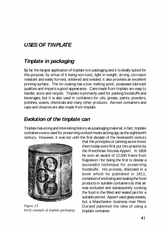
Tinplate has a long and interesting history as a packaging material, in fact, tinplatecontainers were used for preserving cooked meats as long ago as the eighteenthcentury. However, it was not until the first decade of the nineteenth century
Figure 13Early example of tinplate packaging
that the principles of canning as we knowthem today were first put into practice bythe Frenchman Nicolas Appert. In 1809he won an award of 12,000 francs fromNapoleon I for being the first to devise asuccessful technique for preservingfoodstuffs. His process, disclosed in abook which he published in 1811,consisted of enclosing and sealing the foodproducts in suitable containers so that airwas excluded and subsequently cookingthe food in the filled and sealed jars for asuitable period. Appert used glass vessels,but a Manchester business man PeterDurand patented the idea of using atinplate container.
42
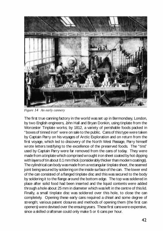
The first true canning factory in the world was set up in Bermondsey, London,by two English engineers, John Hall and Bryan Donkin, using tinplate from theWorcester Tinplate works; by 1812, a variety of perishable foods packed in“boxes of tinned iron” were on sale to the public. Cans of this type were takenby Captain Parry on his voyages of Arctic Exploration and on return from thefirst voyage, which led to discovery of the North West Passage, Parry himselfwrote letters testifying to the excellence of the preserved foods. The “tins”used by Captain Parry were far removed from the cans of today. They weremade from a tinplate which comprised wrought iron sheet coated by hot dippingwith layers of tin about 0.1 mm thick (considerably thicker than modern coatings).The cylindrical can body was made from a rectangular tinplate sheet, the seamedjoint being secured by soldering on the inside surface of the can. The lower endof the can consisted of a flanged tinplate disc and this was secured to the bodyby soldering it to the flange around the bottom edge. The top was soldered inplace after solid food had been inserted and the liquid contents were addedthrough a hole about 25 mm in diameter which was left in the centre of this lid.Finally, a small tinplate disc was soldered over this hole, to close the cancompletely. Opening these early cans required a chisel and some degree ofstrength; various patent closures and methods of opening them (the first canopeners) were devised over the ensuing years. These first cans were expensive,since a skilled craftsman could only make 5 or 6 cans per hour.
Figure 14 An early cannery

43
With the enormous expansion of the American canning industry in the secondhalf of the nineteenth century, developments, both in can design and rate ofproduction, came rapidly. Whilst William Underwood was credited with makingthe first can sold in America in 1819, it was Gail Borden who was largelyresponsible for the wide acceptance of the can as a food container in the 1850s.He introduced canned condensed milk in 1853 and this was responsible for asignificant lowering of the infant mortality figures, particularly in areas wherefresh milk was not readily available, and helped to make the American consumersee the can as a safe, healthy preserver of food. After 1860, the art of canningwas well on the way to becoming the science that it is today.
A major development was the introduction in the 1890s, of the first completemechanised system for making cans, starting from sheets of tinplate andproducing up to 6000 cans per hour. Up until the early part of the twentiethcentury the side seam solder had always been applied to the inside surface ofthe can. However, at this time, the “sanitary” can was developed, so calledbecause the solder was now only applied to the external surface and the endwas fixed by a mechanical double seam.
Whilst the can makers were developing their techniques, materials were alsoevolving. Between 1875 and 1885 steel gradually replaced iron as the basicmaterial for tinplate. From then until 1929, there was a slow but steady evolutionin the procedure for making tinplate. In 1929 cold reduced steel was introduced,thereby providing a more uniform and higher quality product. The importancewas realised of controlling the chemical composition of the steel. Whenelectroplating was introduced by a German chemist in the 1930s as a means ofapplying the tin coating, it represented a major advance in the technology oftinplate, but it was not widely adopted until 1942, when wartime shortagesforced its acceptance, as a means of conserving tin.
A significant new market for the can had become apparent after 1935 when,following the development of suitable internal coatings, the first beer cans weretest marketed.
The tinplate can was further improved in the decade and a half following WorldWar II. Line speed was increased to over 500 cans per minute for each solderingbodymaker and this was accompanied by an increase in quality and reliability.The first semi-automatic side-seam welding machine for can bodies wasmanufactured in 1959, but it was not until 1975 that the first three-piece foodand beverage can bodies were capable of being continuously welded at highspeeds.
Organic coatings, which had already been introduced to increase the resistanceof the can to certain aggressive products, were vastly improved by theintroduction of acrylics, vinyls, epoxies and phenolics. The introduction of an

44
aluminium “easy- open” end in 1962 was highly significant in improving theconvenience aspect and led to increasing sales of beverage cans. The processof drawing and ironing two-piece cans was perfected in 1963, initially inaluminium and, by the early 1970s, in tinplate also. The lighter weight, thin-walled, D&I cans offered many economic advantages. The aerosol container,first introduced commercially in the 1940s, has represented another major outletfor tinplate, where today it is made by both three-piece welding and two-pieceD&I techniques.
Since 1970, canmaking technology has been transformed by the continualdevelopment of the modern techniques of two-piece and three-piecemanufacturing. These are leading to a more economical and cost effective useof materials and consequent reduction in environmental impact. Details of theseand of the older can making techniques are given in the following section.
Three-piece can
The three piece can is so called because it consists of a cylindrical body and twoends. The first modern can design had a soldered side seam on the body but inrecent years this has almost totally been replaced by a can having a welded sideseam body.
Three-piece can - soldered side seam
The first stage in making a soldered three-piece can is the forming of the cylinderwhich constitutes the body. Flat sheets of tinplate are slit into blanks. Theseare notched at each corner of one edge, slits being cut a little way from theends at the outer edge; the edges are then hooked over, one up and one down,at 28° to the blank. Flux is applied to these hooked edges by contact with arevolving wheel partly immersed in flux.
On the bodymaker, the blank is folded over a mandrel so that the hooked edgesengage, whereupon the mandrel expands to tighten the joint and form a cylinder.This lock seam, located on the underside of the can, is next hammered downflat. In the soldering station, the cylinders pass over a gas heater, to pre-heatthe seam, which then slides in tangential contact with the top of the rotatingroll immersed to its centre line in a bath of molten solder. Extra heatingafterwards helps the solder to flow through the seam and a wiper removesexcess solder. A splash eliminator ensures that wipings do not contaminate thecan following the one being wiped. A 98% lead-2% tin solder was commonlyused. However, for certain products other solder compositions, even thoseincluding pure tin side seam solder, have been used.
45
When a fully lacquered interior is required, the side seam may be protected bya side stripe of lacquer, which is applied immediately downstream of thebodymaker. On a soldered can, the heat of soldering is sufficient to cure theside stripe.
Further operations to complete the manufacture of a three-piece soldered canare identical to those used for a welded can and are described in the nextsection.
Three-piece can - welded side seam
Because of its greater integrity and total absence of solder, which may havecontained lead, welding is now the most accepted method of creating the sideseam of a three-piece can (Figure 16). The technique of welding side seams oncan bodies involves producing a series of overlapping weld nuggets along thelength of the seam, using a suitable alternating current supply and copperelectrode wheels. A problem with welding tinplate with copper electrodes isthat as the tin melts it tends to alloy with the copper, thus altering the electricalcharacteristics. This has been overcome by using a copper wire as anintermediate electrode material. The wire is threaded over the rims of twoelectrode wheels and being slightly proud of the surface of the electrode makesdirect contact with the tinplate surface; as the tin melts it is carried away on thewire and fresh copper is available for further welding. Immediately prior to thewelding operation, the wire is flattened to a rectilinear cross section so as toprovide a greater surface area.
On the bodymaker line, a tinplate blank is formed into a cylinder with suitableoverlaps, approximately 0.4 mm, and firmly held in position by calibration rollersduring passage through the unit. The welding electrodes (wheels carrying copperwire as described above) are situated one above the other. The lower electrodeis smaller in diameter than that of the can body and the cylinder moves in sucha way that the lower electrode is inside it; the seam thus lies between the twoelectrodes. When the current is passed between the electrodes, a series ofspot welds is produced as the container moves, these constituting a continuousweld. The upper electrode, which is outside the can, is mechanically loaded sothat the two layers of overlapping tinplate are squeezed together as they passbetween the two electrode wheels. The result of this is a mechanical weldwith total thickness equivalent to approximately 1.4 thicknesses of body metal.After the welding process has been completed a layer of oxide will form overthe weld on both the inside and outside of the can. If it is necessary to providea lacquer coating over the side seam weld and to later form beads in the wall ofthe can, it is usually necessary to prevent the build-up of a heavy oxide layer onthe weld by providing an inert gas shield for the welding process. Failure to do

46
Figure 15Selection of tinplate cans showing the diversity of packaged products
Figure 16A Soudronic machine for making three-piece welded tinplate cans

47
this may result in lacquer breaking away from the weld area during thesubsequent beading operation.
The quality of the weld may be continuously checked by an in-line electronicweld monitor device. This checks that the electrical current conditions foreach nugget of the weld are within the parameters set by the operator forproduction of a satisfactory weld. The device may be set to alarm orautomatically remove cans from the line when the weld conditions fall outsidethe set parameters.
Many tinplate cans are protected on their internal surface by a lacquer system;the types of lacquer and number of coatings applied depend on the intendedcontents of the can and the specific processing requirements. The exteriormay be protected by a decorative system which may be a combination of aclear size coat, or solid base coat, plus printing inks and over varnish. Lacquersare formulated to give corrosion and process resistance in conjunction withadhesion, flexibility, non-toxicity and freedom from taint. Film thicknessesgenerally lie in the range 1.5-10 µm. The essentials of the lacquering processesare described in standard texts. (See also Chapter VI).
Many tinplate cans have a plain exterior, with paper labels applied to identifythe products. However, where the exterior of three-piece cans are to bedecorated, the tinplate sheets are printed in the flat, prior to being slit intobody blanks. Similarly, internal lacquer coatings are applied by roller coating tothe flat sheets, normally in a stencil pattern to leave the seam margins free fromlacquer.
Side seam lacquering on the welded can is carried out immediately after makingthe welded joint. It may be done using either a liquid or a powder coatingmaterial. In each case the coating is then cured by a gas fired heating device.
Following body forming, the subsequent operations are identical for bothsoldered and welded side seam cans.
When the height of a three-piece can is equal to or less than its diameter it isrelatively unstable when being fed at high speed through a bodymaker with theaxis of the can horizontal. For this reason, it is common to initially form aseamed can body which is two or three times the height of a single can. Afterthe soldering or welding operation this long body is then passed through a partingmachine which separates the long body into two or three short bodies, asappropriate. From this point onwards the can bodies are then conveyed withtheir axes in the vertical position.
Three-piece beverage can bodies are very often necked in at both top andbottom, so that the diameter over the seam is equal to or less than that of thebody itself. There are a number of reasons why this is done; the uninterrupted

48
body wall allows for easier handling of cans at high speed, particularly duringcollating of filled cans into cardboard trays, and permits the cans to be packedinto a smaller volume; also the reduced flange diameter permits smaller diameterand, sometimes, thinner ends to be fitted with a consequent reduction in metalusage and therefore cost.
For food cans, inward necking of the top (opening end) of the can body may bedone if the product consistency is such that emptying the can is not made difficultby the reduced diameter of the seam. In some cases the top of a food can maybe necked outwards to facilitate product removal, particularly when a fullaperture easy-open end is fitted. Inward necking, of the bottom end only, of athree-piece food can is done to permit easy stacking of filled cans.
The next step is to flange the top and bottom edges of the cylinder so that arim is formed at 90° to the vertical axis of the cylinder; the condition of thebase steel, in particular freedom from inclusions and the correct temper, aswell as rolling direction of the steel, are important if flange cracking is to beavoided. The use of spin flanging as opposed to die flanging is also important inthis respect.
The bottom end is fixed on to the body at the double seaming machine, wherethe closure is attached by the operation of two-stage seaming rolls whilst thecan is spinning about its vertical axis. For beverage cans it is usual for thecanmaker to fix the easy open end to the can at this point, leaving the plain endto be fixed by the can filler. This sequence of events permits the easy open endto be pressure tested after it is fixed to the can and as a routine part of the canmaking operation. Manufacture of can ends is described in a later section of thisChapter.
For food cans, which will be passed though a heat processing cycle after fillingwith product, the side wall must have sufficient strength to withstand theconsiderable external forces acting on it during the sterilisation process. Thismay be achieved by either making the wall of sufficiently thick material that itwill withstand these forces as a plain cylinder, or reinforcing the wall by additionof numerous circumferential beads and then utilising a much lower gauge ofmaterial. For economic reasons the latter route is the more common way ofmaking processed food cans today.
For non-beaded cans that may require further body shaping operations, such asbulging or embossing, the appropriate operation will generally be introduced atthis point in the process.
Finally, the can’s integrity is checked in a leak tester, typically, a rotating carouselarrangement on which cans are mounted; testing occupies one full turn of thecarousel and consists of electronically monitoring the rate of pressure loss

49
when the open end of the can is sealed by a pad and compressed air introduced.Defective cans are rejected whilst sound cans are either fed directly to thefilling lines or to a palletising station for onward shipment to a can filler.
Shallow drawn cans
Shallow containers, made by a single draw from a flat sheet of tinplate, may befinished cans for products like sardines or pies or they may be the first step inthe manufacture of two-piece deep drawn containers which are described next.Shallow drawn cans may be round or square in cross-section and, with theapplication of special forming techniques may be produced with tapered wallsin a single draw. Tapered walls permit the empty cans to be nested for moreeconomical shipment over long distances. Single draw cans for food or generalline purposes provide an ideal application for the use of distortion printedtinplate.
Drawn and wall-ironed cans
The development of the draw and wall ironed (D&I) can began in Switzerlandduring the Second World war when tinplate became virtually unobtainable for
package manufacturing andaluminium was the only othermaterial available. As aluminiumcould not be used for makingthree-piece cans, it was necessaryto develop a seamless form of canbody instead. Some twenty yearslater, in 1963, the first commercialaluminium D&I beer cans weremade and filled in the USA. Onlywhen the steel substrate could bemade clean enough could the D&Iprocess be adapted to use tinplate.The major application for the D&Ican is for beer and beverage cans,although the use of tinplate D&Icans for both human and pet foodsis now well established in both theUSA and the UK. D&I cans aremost appropriate where largevolumes of cans with similar
Figure 17Flow line for the manufacture of adrawn and ironed two-piece tinplate can

50
specifications are required. In these situations, where cans with a large heightto diameter ratio are required, the D&I process is the most economical of allthe known can manufacturing processes in terms of metal utilisation.
Figure 18Schematic view of the wall ironing processin two-piece D & I can manufacture
The cups then enter the wall ironing bodymaker. Modern commercial unitsare single action horizontal power presses, with redraw facility, capable ofoperating at 300 - 500 strokes/min. depending on can type and size. A specialpunch, which has the same external diameter as the inside of the finished can,forces the cup through a series of annular dies (Figure 18), the first of whichredraws the cup to the finished can diameter; the remaining dies iron the wallof the can, reducing its thickness and at the same time increasing the overallbody length. The base remains constant in thickness and diameter during theironing process. At the end of the forward stroke, after the can has passedthrough all the wall ironing dies, its base is domed to give it greater strength.The ironing results in a very bright finish on the formed body. The can isremoved from the punch, after forming, by a stripping mechanism. It thenpasses to a trimmer which removes the irregular top edge and leaves a can shellwith the precise wall height required for later forming operations. Trimmedcans travel to a washing unit where they are chemically cleaned, to prepare thesurface for receiving exterior and interior organic coatings. Because of the
Plain tinplate, in coils ofapproximately 10 tonnesweight and up to 1200 mm inwidth, is the starting materialfor D&I can manufacture(Figure 17). The tin coating isnormally left in theunflowmelted state tomaximise the amount of free tinavailable to act as a lubricantduring the wall ironing process.Prior to the first formingoperation a water baseddrawing lubricant is applied toboth sides of the metal. Usinga double action cupping press,multiple discs are blanked-outacross the full width of the coiland then, in the same toolingstations, drawn into shallowcups (for 33cl cans, dimensionsat this stage are typically 82mmdiameter and 34mm height).

51
extreme deformation which the metal had to undergo during the drawing andironing process, it was necessary to virtually submerge the can in a continuouslycirculating lubricant / coolant. All traces must therefore now be removedduring the washing operation. Proprietary chemical cleaners are used for thispurpose followed by rinses in fresh and finally de-ionised water.
The next stages are coating and decorating. Unlike three-piece cans, the metalcannot be decorated in the flat and special coating and printing units are employedto operate on the external surface of the cylindrical body. Whilst the decorationis still wet, a coat of varnish is also applied to the bottom rim and part of theconcave dome of the base. The whole is then cured. Protective lacquer issprayed inside the cans followed by baking to remove all the solvent and curethe coating. Two interior coatings may be applied, with curing after eachapplication, especially when soft drinks are to be packed. For drinks cans, thefinal operations involve a reduction in diameter of the top of the can (necking-in), followed by outward spin flanging to prepare the can for closure. Necking-in allows the end seam to be kept within the diameter of the can body for easeof stacking. It also allows a smaller diameter can end to be used, providingmaterial savings. For processed food packaging, the D&I can is not necked-inbut has a flange formed by spinning. The walls are then beaded for additionalstrength, to prevent implosion of the can during the thermal sterilisation process.Finally, all cans are tested to ensure freedom from leaks.
Figure 19 The drawn and ironed tinplate can: stages of manufacture

52
Figure 20 Commercial DRD cans
53
This D&I can-making process imposes severe requirements on the quality ofthe steel substrate. It must be clean to avoid an unacceptable level of wall splitsor flange cracks; composition must be controlled to give correct temper andformability; drawability and earring can influence operational performance, e.g.stripping from punches; the number of pinholes and welds must be controlled;gauge control within strict tolerances is essential.
Draw-redraw cans
Seamless two-piece cans are also produced by a sequential drawing operationknown as draw-redraw (DRD). In this process, the can walls are not thinnedand therefore containers may have sufficient strength to withstand processingwithout body beading. These cans are suitable for holding foodstuffs such astuna fish, salmon, some fruits, vegetables and meats. However, the walls ofDRD cans are thicker than is strictly needed which is wasteful in material. Sizesare best restricted to those with small height to diameter ratios where thematerial contained in the can wall represents a lesser proportion of the total.The process has considerably lower installation costs than drawing and ironingand is generally best suited to smaller annual production volumes e.g. 50-200million per annum. Line speeds for DRD are normally in the range of 50-1000cans per minute.
In the draw-redraw process, can bodies are produced in two or more stagesfrom flat pre-coated tinplate. The number of drawing stages depends on theheight to diameter ratio of the container required. The material used for DRDcans is usually pre-coated with lacquer or polymer film on both sides in eithercoil or sheet form.
The material is fed into the first stage, which cuts a circular blank and draws ashallow cup in one operation. The press used for this operation is similar tothat used for cupping in the D&I process. These cups are then transferred to asecond press for redrawing. Normally this press will also form the base panel inthe can. The last drawing operation is usually not completed, leaving a flange ofuneven width. The flange is then die trimmed to leave a clean edge of consistentwidth for seaming.
Cans may be beaded to give the walls extra rigidity. The bottom portion of thecan wall may be stepped-in to permit easy stacking. Tapered cans have alsobeen developed, principally for salmon products, which are fully nestable toreduce shipping costs. Irregular (oval and rectangular) DRD cans are alsoproduced by the same basic process for various fish and meat products.
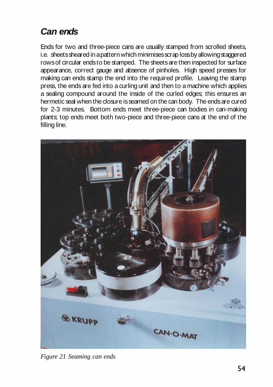
54
Can ends
Ends for two and three-piece cans are usually stamped from scrolled sheets,i.e. sheets sheared in a pattern which minimises scrap loss by allowing staggeredrows of circular ends to be stamped. The sheets are then inspected for surfaceappearance, correct gauge and absence of pinholes. High speed presses formaking can ends stamp the end into the required profile. Leaving the stamppress, the ends are fed into a curling unit and then to a machine which appliesa sealing compound around the inside of the curled edges; this ensures anhermetic seal when the closure is seamed on the can body. The ends are curedfor 2-3 minutes. Bottom ends meet three-piece can bodies in can-makingplants; top ends meet both two-piece and three-piece cans at the end of thefilling line.
Figure 21 Seaming can ends

55
Ecology easy-open ends [“Stay-on-tab”] are widely made in aluminium forbeverage cans. For such ends, the limits of the aperture are scored in the metaland a tab is riveted in place so that on lifting the tab, the aperture is rupturedinwards allowing access to the contents. The tab and aperture remain attachedto the end. Different aperture shapes are available, the most common beingoval. Increasingly, a “Gulper” or large opening end [LOE] is being used as thisallows the product to be dispensed more rapidly from the can. Manufacturingspeeds continue to rise substantially with multi-die shell and conversion pressespredominating.
A number of beverage tinplate easy-open ends have been developed thoughnot widely commercialised; with a harder, springy material like steel, the scoringoperation is even more critical since the scoring must be deep enough topermit detachment by pulling, yet not so severe as to introduce a risk of leakage.Furthermore, there must be no damage to fingers from sharp edges. Onedesign developed in Australia has a press-button can end for beer and softdrinks cans. There are two circular press tabs of different sizes. These tabs areintegrally hinged to the end and cannot be detached, thus they neither fall intothe can contents nor add to litter problems. The end is opened by first depressingthe smaller tab to release gas pressure and then depressing the larger tab toallow the contents to be poured. In a modification the smaller tab is situated
Figure 22 Easy-open can end
56
inside the larger opening; this obviates the risk of contents spurting out whenthe buttons are pressed in. These ends are manufactured by subjecting a normalend to a series of stamping operations, using transfer presses to form the tabsand apertures, applying a sealant around the internal cut edges to preventcorrosion and to provide an hermetic seal and coating the external cut edgeswith a repair lacquer. Tolerances for the die stages are said to be less criticalthan in the case of ring-pull openings and only low press tonnages are needed.
Aluminium and tinplate full aperture easy-open ends have been developed forboth dry and processed foodstuffs. Normally, the full-aperture end is operatedby a riveted ring-pull, similar to that used for beverage containers but detachingwith the centre panel of the end. The end is scored circumferentially close tothe end seam, so that the maximum area of the end is open when the panel isremoved. Steel provides better performance for a given end thickness and istherefore more common where the food processing produces high internal canpressures. Harder steels have been the trend with much development aroundthe industry currently focused toward using double-reduced steel. This lattermaterial is already common for classic [non-easy open] ends. With steel inparticular, careful attention must be paid to all stages of the manufacturing processif a high level of end consistency is to be achieved. The achievement of acceptablylow opening forces requires similar attention to product design.
Some aluminium full aperture ends have folds along one or both of the scoreedges as a safety feature. These are generally manufactured by collapsing astepped shell profile in the conversion press during end manufacture.
Certain meat and fish packs have key opening. In the case of the meat packs,normally in rectangular cans, a narrow strip is scored into the can wall. This isremoved from the body by inserting a tag from the strip into a metal “key” andwinding off a metal strip, thus releasing one end of the container. In the case ofshallow drawn containers for fish, one end is scored around the perimeter andthe entire end is wound off using a detachable “key”.
Closures
In addition to ends for cans, tinplate is used to make bottle closures e.g. crowncorks with characteristic corrugated rims and cork or plastic pad as sealant,ensuring a tight hermetic seal when applied to a bottle. Sheets of tinplatedecorated with the bottle top pattern, are coated with wax and then passed toautomatic presses which produce the bottletops from a series of dies. A blankingpunch cuts out the cap and the drawing punch passes through to form thecrown. After blanking and forming, the closures are lined with compositioncork, or moulded polythene reseals, or flowed-in plastic liners.
57
A wide range of other glassware closures is produced in pre-decorated tinplate.Pre-formed screw caps are produced on special presses from decorated andlacquered tinplate and contain a plastic liner to ensure an hermetic seal. “Twist-off” closures are also made from tinplate stamped from sheet.
Aerosol containers
The aerosol container has been a recognised form of packaging since it was firstintroduced during World War II as a heavy gauge dispenser designed to withstandlow pressure. Since then, it has undergone many modifications in design andconstruction and its use is constantly increasing at an annual rate of 3 to 5%world-wide (production of roughly 10 billion units in 1996/1997) to pack a widerange of products, including personal care, household, automotive, industrial,paints and varnish, pharmaceutical and recently food products.
Metal is the predominant material used in the manufacturing of aerosol containersand steel for packaging (tinplate and electrolytic chromium coated steel) has byfar the greatest share of the market world-wide.
The standard steel aerosol container is a 3-piece can, with diameters varyingfrom 45 to 65mm. It offers a range of internal pressure resistance from 12 to18 bars with the advantage that the can body does not need to be changed nomatter what the pressure is. Indeed, only the cone and/or the dome have to bemodified when pressure specifications vary.
The thickness of the steel for packaging used for aerosol applications rangesfrom 0.18 to 0.23 mm for the body and from 0.26 to 0.36 mm for the endcomponents. Tin coating weight is most usually E 2.8/2.8.
The tinplate base of the aerosol container has a concave profile to increase itspressure resistance and safety requirements for internal pressure resistance upto 18 bars imply that pressures at least twice these must be withstood in testing.After the curl has been lined with sealing compound and cured, it is doubleseamed in place in the usual manner.
Constant technical developments have helped in improving the technicalperformance and appearance of the welded seam of the 3-piece steel aerosolcan body. Indeed, today the electrical welding process is constantly being used,which allows printing closer to the seam. Moreover, the use of powder coatingsapplied internally on the side-stripe area of the welded can protect the innerface of the weld seam from highly corrosive products.
The top section of the aerosol container is a much more complex shape andits production may involve as many as seven successive tooling stages in atransfer feed press, starting from a flat steel disc. The disc is first drawn to a

58
dome shape, then re-drawn in a more complex profile, pierced at the centre,“blocked and guttered”, trimmed to restore exact circularity, curled at the topedge and finally curled at the bottom edge, for attaching to the body in a doubleseam. The tops are lined and cured before being attached to the body. Afterleak testing, the containers are palletised for despatch to the filler. Contentsare inserted through the top aperture and a valve cup, also usually in tinplate, isswaged in position to complete the closure.
Butane/propane is today the standard propellant used in aerosol containers.There are various ways of inserting the propellant, by injection into the completedcan through the valve system or by inserting the propellant through the aperturejust before swaging on the valve cup (as refrigerated propellant or after creatinga vacuum in the container).
Recent years have seen many technical and technological developments in steelaerosol can manufacturing, and among these major changes are the following:
The 38mm diameter 2-piece steel aerosol can, consisting of a welded body anddome, opens the market of small size aerosol applications to steel cans. Thiswas made possible by the development of a new process enabling welding ofthe body of narrow steel cans electrically. Moreover, the coneless aerosol canrequired the development of an ultrasonic necking process which allows standardaerosol valves to be used.
The 2-piece steel aerosol can uses the DWI technique, which means a can bodywithout seam. Together with economic benefits which mainly result from
Figure 23 DWI aerosol cans
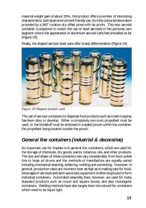
59
material weight gain of about 20%, this product offers a number of interestingcharacteristics, such as an environment friendly can, its richly coloured decorationprovided by a 360° rotation dry offset press with six prints. This new aerosolcontainer is expected to widen the use of steel aerosols in the personal caresegment where the appearance of aluminium aerosol cans had prevailed so far(Figure 23).
Finally, the shaped aerosol steel cans offer brand differentiation (Figure 24).
Figure 24 Shaped aerosol cans
The use of aerosol containers to dispense food products such as cream topping,has been slow to develop. Either a completely non-toxic propellant must beused, or the foodstuff must be enclosed in a sealed pouch within the container,the propellant being located outside the pouch.
General line containers (industrial & decorative)
An important use for tinplate is in general line containers, which are used forthe storage of chemicals, dry goods, paints, tobaccos, oils, and other products.The size and shape of these containers can vary considerably, from boot polishtins to large oil drums and the methods of manufacture are equally variedincluding mechanical seaming, soldering, welding and cementing. However, ingeneral, production rates are nowhere near as high as in making cans for food,beverages or aerosols and semi-automatic equipment is often employed to formindividual containers. Automated assembly lines, however, are used for manystandard products such as round and square boxes, and also rectangularcontainers. Welding methods have also largely been introduced for containerswhich need to be liquid tight.

60
Decorative tin boxes have a long and colourful history and many are todaycollectors’ items (Figure 25). The starting material is decorated tinplate sheetwhich is subjected to a series of manual forming operations. Joints are mademechanically, by engaging hooked edges and rolling flat, since the containers donot need to be hermetically sealed. Lids have their edges curled over, to avoidsharp edges and to ensure a good fit on bodies. When hinged lids are needed,wire may be inserted in specially made flaps in the body wall and an extra largeflange on one edge of the lid is fitted around the wire, the whole being flatteneddown to secure the wire in place. There is also a technique available wherehinges are made without the use of wire and interlocking cut-outs are made inboth the lid and the body. In the case of circular tins and square tins with roundcorners, the body may be made by forming a blank into a cylinder in a singledraw operation and then mechanically seaming on a ring onto which to mountthe lid. Distortion printed sheet would normally be used for this process.
Figure 25 A selection of fancy boxes
For containers such as paint cans, up to one litre capacity, mechanical integritymay be ensured by applying a special cement along the side seam before finishingand finally heating the container to cause the cement to flow in the joint,although today many such cans are likely to be of welded construction. In thecase of large 20-25 litre drums, the seams will usually be welded. Tops and
61
bases are stamped from tinplate sheet and seamed in place. Handles are alsomade from tinplate and are secured by spot welding. Depending upon theapplication, the tinplate thickness may vary from 0.18 to 0.41 mm and the tincoating masses from E1.4/1.4 to E8.4/8.4.
Special technical packs
The fabricability and the corrosion resistance of tinplate, lacquered if necessary,make it particularly suitable for containing chemical and other industrial productssuch as adhesives, sealants and fuels. Rectangular packs provide a betterutilisation of transport volume: 30 litre rectangular containers allow twelve tobe stacked on a standard pallet, as opposed to six cylindrical ones. They alsohave good rigidity. Tinplate screw caps are often used for chemical packs; testshave demonstrated that such closures can withstand considerable deformationbefore any leakage is observed. Two-piece cans with a diameter of 72 mm anda height of 112 mm have been produced by drawing in a multi-stage operation,starting from 0.34 mm thick killed steel base material with an E 8.4/8.4 tincoating. This type of can is stated to be resistant to 10 atm pressure withoutpermanent deformation and is approved in Germany for use with poisonousproducts up to 370ml volume. Two-component containers have been producedfor packaging two compounds which have to be reacted together shortly beforeuse. In one design, the upper portion constitutes both the lid for the lowervessel and a container for one of the reactants. The upper container has aconical form and is made by a combination of drawing and spinning, using tinplatewith a tin coating of E 8.4/8.4 or E 11.2/11.2.
Engineering uses of tinplate
The excellent fabricability of tinplate, its solderability, attractive appearance,and corrosion resistance have led to a diversity of other uses besides packaging,although none of these individual uses represents a large tonnage outlet. Anumber of automotive applications exist, such as in the manufacture of enginegaskets, brake line tubes and oil filters.

63
CAN PERFORMANCE
Tinplate’s long and successful record as a packaging material is due to itsconsistent performance in preserving packaged goods so that they are intactand still in good condition when the container is opened. The favourableproperties of tinplate are important in this connection, but just as important isthe research and development work which goes into understanding theinteractions which can take place between the container and its contents andinto tailoring the properties of the packaging material so as to overcome possiblecorrosion problems. In order to understand the can/product system, it is usefulfirst to look briefly at the canning process.
Canning of foodstuffs
The purpose of canning foodstuffs is to preserve the freshness of the product.Close co-operation is maintained between farms and canneries and the latterare usually situated in the principal farming areas. Once fruit or vegetables arepicked, care is taken to see that the food is packed within a few hours whilst inthe peak of condition. It is interesting to note that whereas “canned” foods arecommonly contrasted with “fresh foods”, in fact the contents of the can areoften hygienically and nutritionally superior to fresh foodstuffs which have beenon display for a day or so at a retail outlet.
The principal foodstuffs, which are canned, comprise: fish, fruit, meat, milkproducts, pet foods, soups and vegetables. At the cannery the food is inspected,cleaned and graded; when necessary it is prepared by peeling, shelling, cutting-up, etc. In some cases the food is given a short cook so that any initial shrinkagetakes place before the can is filled. As will be seen later, the amount of air inthe headspace must be kept as low as possible, to avoid corrosion problemsand after filling, the can closure is seamed on. The vital step in the canning offoodstuffs is that of sterilisation. The filled and sealed cans are passed througha processing unit in which they reach the required temperature (typically 115-127°C for vegetables) to kill bacteria which could be harmful to health, orcause spoilage of the contents. The contents are also cooked during thisprocessing so that they require little or no further preparation. The slightvacuum in the can prior to this heating helps to avoid expansion of the container

64
during processing and the cans are rapidly cooled after the heating stage.
In general, meat, fish and soups in cans may be stored for some years withoutany deterioration in quality. In the case of beverages, these are pasteurised byheating the can, and a sterilisation cooking process is not required.
The container/product system
Food products and beverages are all extremely complex systems, which candiffer with respect to pH, buffering properties, content of corrosion inhibitorsor accelerators, and consistency of product. Foodstuffs may be broadly classifiedinto categories such as “highly corrosive”, “moderately corrosive”, “slightlycorrosive”, “highly detinning” etc., on account of their typical behaviour.However, a number of variables may intervene to alter the pattern of behaviour.These factors include: biological variance in the natural product; trace residuesfrom exterior influences such as heavy use of fertilizer, use of pesticides, feeding;processing effects, e.g. pre-treatment with sulphur dioxide; and specific fillingconditions which influence the amount of oxygen in the headspace of the can.
Can performance
Optimum can performance depends on controlling the electrochemical reactions,which tend to occur within the can/product system. Some effects, which mayappear, are general type corrosion, which proceeds gradually and tends to spreadlaterally rather than penetrating metal at localised points. It can be controlledwithin acceptable quality limits by good canning, storage and distributionpractices. Pitting type corrosion occurs at sharply localised areas and tends toperforate the metal with very little visible evidence and without noticeable effecton product appearance, although it may eventually result in leakage and
Figure 26Schematic representation of electrochemicalprocesses taking place in a tinplate can
Fe
H2 EVOLUTION
ELECTROLYTEUNATTACKEDIRON
CATHODE ANODE
Sn
TIN SLOW LYDISSOLVES
FLOWOF ELECTRONS
Sn 2+-
e corr- i bacteriological spoilage of thecan contents. It can be avoidedby proper matching of productand can material systems.
To visualise the corrosionprocesses which may occur in afilled can, it is helpful to considera simple model (Figure 26). Inthe case shown, when tin andiron electrodes are immersed inan electrolyte, each will developan uncoupled potential, which

65
can be measured by suitable means. In connecting the two electrodes, electronswill flow through the circuit and polarisation will take place at the electrodes.At equilibrium the electron flow will constitute the corrosion current icorr. Atthe tin electrode tin will pass into solution slowly as ions and electrons will bereleased to electrolyte at the iron electrode resulting in evolution of molecularhydrogen. One would expect iron to be anodic to tin and in fact in solutions ofmineral salts or in the atmosphere, this is the case. Fortunately, in the presenceof many natural products and with limited oxygen supply in the food can, thereverse is the case. This is because the complexes which tin forms withcarboxylic acids reduce the concentration of free tin ions to low levels, and theself-corrosion of tin in the absence of cathode depolarisers is very small, due toits high hydrogen overpotential. Therefore, in unlacquered cans, when steel isexposed to the can contents (at pores or scratches), in the absence of oxygen,tin dissolves preferentially. In view of the relatively large area of tin comparedto exposed iron, this tin dissolution occurs smoothly and slowly; the presenceof dissolved tin also inhibits the cathodic reaction on exposed steel and the neteffect is a long period of an almost steady corrosion rate lasting until substantialareas of steel are exposed and iron begins to pass into solution. Hydrogenevolved at a slow rate in the initial period of corrosion seems to pass into, orthrough, the steel but at the later, faster, stages of corrosion, considerablequantities of hydrogen are produced, which will eventually distort the shape ofthe can. Such “hydrogen swells” are considered unacceptable since they cannotbe distinguished visually from those which would arise from bacterial activity inthe can, and such damaged containers must be discarded. However, due to theprotective action of the tin in a largely oxygen-free environment and since inmany natural products tin complexes are formed which inhibit corrosion,hydrogen swells normally occur only after a longer period than the expectedshelf life of the product at the point of sale.
In some foods, the difference in corrosion potential between tin and steel maybe small; coupling tin and steel together in such a foodstuff alters the steelpotential but not sufficiently to provide complete cathodic protection. Thus,iron exposed at pores may dissolve and the cans fail by perforation. Theformation of films on tinplate, for example by reaction with sulphur-bearingcompounds, may also result in pitting; film formation hinders the anodic reactionon tin and hence its ability to protect exposed steel.
An important influence on the rate of dissolution of tin is the presence of cathodedepolarisers such as oxygen, nitrate or sulphur dioxide, which permit analternative cathodic reaction to the reduction of hydrogen ions to hydrogen.The presence of dissolved oxygen in the electrolyte thus greatly increases thecorrosion rate of tinplate. Oxygen reduction to hydroxyl ions proceeds rapidlyon tin, the rate of the reaction being frequently governed by mass transport

66
rather than electrochemical influences. Oxygen is initially present in the canheadspace and this leads to an initial period of tin dissolution after which therate slows down when all the oxygen is consumed. Elimination of oxygen priorto can closure thus greatly contributes to shelf life. Other depolarisers, whichcan accelerate the corrosion rate, are nitrates, colouring matter in dark fruits,copper traces and so on. Nitrates, which may arise from fertiliser residues,have been particularly troublesome on occasion. Some compounds, such assugars and starch products are believed to act as corrosion inhibitors.
So far, only the simple system: steel with a tin coating, has been considered butin practice, tinplate is a much more complex system, as can be seen from Figure27 which, in section, illustrates the various layers present on the steel surface ina commercial tinplate.
The iron-tin intermetallic compound which is formed by reaction between thetin coating and the steel substrate, largely during flow melting, plays an importantpart in determining the corrosion resistance of the tinplate. As will be describedlater, the alloy-tin couple (ATC) test (see Chapter VII) is important as an indicatorof alloy layer continuity in a citrus pack application, a factor related to shelf life.Once a considerable amount of tin has dissolved, this alloy layer constitutes asecond line of defence for the underlying steel and also slows down dissolutionof tin by reducing the iron cathode area.
Depending on the type and intensity of the electro-chemical treatment, thepassivation film on tinplate consists of tin oxides and various amounts ofchromium(III) oxide and metallic chromium. Treatments can be adopted so asto produce various film compositions to meet particular end-use requirements,but in practice only a few specific treatments are applied.
Figure 27 Layers existing on the steel substrate in commercial tinplate
0.002µmOIL
0.002µmOXIDE
0.35µmTIN
0.15µmTIN-IRON
COMPOUND
200µmSTEEL
0.002µmOIL
0.002µmOXIDE
0.35µmTIN
0.15µmTIN-IRON
COMPOUND

67
Performance of lacquered cans
Many cans today are protected with internal lacquers (sometimes called enamels)and this changes the whole corrosion situation. One of the prime reasons foremploying a lacquer coating is to prevent tin dissolution, enabling a lower tincoating mass to be used. Lacquers improve the appearance of the can at themoment of opening; they also allow lower tin coating thicknesses to be adopted.However, this means that a large tin area is no longer freely available as ananodic protective surface, and the integrity of the lacquer coating becomesimportant for complete protection. For many foodstuffs, the porosity of alacquer is not important. However, for aggressive products lacquer helps toprotect the can during its life. If the products modify the electrochemicalbehaviour so that iron is preferentially attacked, then lacquer improves thesituation. Care must be taken, however, for if there is a tendency for pitting tooccur in a plain, unlacquered can, then a thin lacquer coating can only accentuatethis effect.
The question of whether to employ a plain or a lacquered can depends on anumber of factors, including the type of product to be packed, the intendedshelf life and the wishes and requirements of the consumer. For certainapplications some tin dissolution is desirable, both to retain flavour andappearance of a product. In the absence of dissolved tin, some darkeningfrequently occurs in pale products and changes of colour may become visiblein green vegetables. Dissolved tin may also have a perceptible effect on theflavour of many products, sometimes by removal of sulphides, sometimes bysuppressing the adverse effects of dissolved iron. Thus ideally, the canner seeksto reconcile requirements for a good can appearance, dissolved metal contentswithin acceptable limits and desired appearance and flavour. One approach hasbeen to employ a plain tinplate can body, with lacquered ends; another deviceconsists of the so-called “high tin fillet” which is a fully lacquered can but witha special side seam so sealed with pure tin, that some tin is exposed within thecan.
Acidic aggressive products may be protected by a combination of lacquercoatings, for example a roller coating applied to the starting tinplate sheet, aside stripe applied over a side seam and a final overall spray coating. Thisprocedure is usually adopted with beverage cans and containers for beer, whosetaste is particularly susceptible to the presence of small amounts of dissolvedmetal.

68
Factors influencing lacquer performance
Failure of a lacquer to wet the tinplate surface completely produces circular orelliptical gaps in the cured coating, commonly known as “eye-holes”.
Causes include the presence of dust particles, excessive residues of oil,application to chilled sheets and surface incompatibilities. Difficulties in wettingmay sometimes be overcome by a preliminary heating of the tinplate beforeapplying the lacquer; this is rather expensive and is only adopted as an interimmeasure until compatibility can be assured.
Adhesion is an important lacquer property and failure may take at least threeforms. Cracking and lifting may occur during mechanical deformation, forexample at a seam, bead or ring. Detachment may occur during heat processing,particularly in the case of exterior coatings. Undermining may occur by corrosion,often by spread from a scratch or other discontinuity in the lacquer coating.
The passivation treatment, which the tinplate receives, has a significant effecton lacquer adhesion. Both weak and very strong passivation treatments may bedeleterious under certain conditions and a treatment which gives a total surfacechromium of about 0.5 µg/cm2 is often favoured for tinplate which is to belacquered. This provides a surface that remains adequately stable in storageand can be produced consistently.
The surface roughness of the tinplate and possibly the thickness of the tin coatingmay be influential as regards lacquer adhesion. Deliberately rough, special surfacefinishes may have disadvantages, whilst very thin tin coatings may produceadhesion failures at points of intense deformation where the free tin coatingmay be dispersed. Tests which are commonly adopted to assess lacquerperformance are described in Chapter VII. These are concerned with coatingcontinuity and with adhesion and its loss by deformation or undermining.
Protecting can contents
Whereas protecting the integrity of the container is an essential requirement,no less important is the need to ensure that the can contents are protectedfrom bacteriological attack and from contamination by traces of harmfulsubstances. It is important, when tinplate containers are opened by theconsumer, that they show no changes in appearance internally or in the characterof the can contents. Even if certain changes are not associated with harmfuleffects, nevertheless they are not acceptable if they suggest deterioration tothe consumer. There must be no uncharacteristic changes in flavour, colour ortexture of the foodstuff and the pack must conform with regulations regardingmetal content of the packed product.
69
As has been shown, the electrochemical processes taking place within a canoften involve the dissolution of some tin. It is well established that no ill effectscan be attributed to regular long term ingestion of tin at the levels normallyencountered with good canning practice. A few instances have been reportedof temporary irritation of the gastro-intestinal tract caused by ingestion ofproducts with abnormally high tin contents. However, once the tin was voided,no long term harmful effects were experienced. It should be emphasised thatonly tin in solution appears to cause these temporary upsets at high levels; insolid foods, most of the tin appears to be combined with food constituents suchas proteins and is rendered innocuous. In many countries, a limit of 250 ppm tinhas been accepted for many years as a working recommendation for tin infoodstuffs. In the UK, a tin in food legislation was published in 1992, setting thelimit for the level of tin in food at 200ppm. It has been suggested that lowerlimits might be applied to some special categories of canned products, forexample baby foods and fruit juices. Extremely small amounts of tin may causesome loss of clarity in beer and the flavour of this product is extremely sensitiveto trace metal content, so that multiple lacquer coatings are used for the interiorof such cans.
Restrictions on the metal content of foodstuffs are under constant review, eitheras legislation or as recommendations which have some legal significance. Nationaland international standards are continually being revised and changes in permittedlevels are made from time to time.
Sulphur-containing compounds, including proteins and allied substances, occurnaturally in most animal and vegetable products. During heat processing, thesecan break down to give free sulphide and hydrosulphide ions and evolution ofhydrogen sulphide. Serious discolouration may occur on unpassivated tinplateor at scratches on passivated surfaces. Hydrogen sulphide in the headspacemay, at pH less than 6, cause formation of iron sulphide, which may detach so asto discolour the contents of the can. Lacquering should overcome the problemof sulphide staining; for products known to produce this effect strongly, internallacquers pigmented with zinc oxide may be used. These have only a slightpearly appearance and the zinc sulphide which is formed, is similarly a whiteproduct, so that no colour change occurs. It should be noted that sulphidestaining affects only the appearance of the can interior and has no actual harmfuleffect on the foodstuff.
When considering grades of tinplate for packing particular products, it is possibleonly to provide general guidelines. Natural products vary in their corrosiveeffect with place of origin, with season, and with harvesting and other processesthat precede canning. Other factors, which play a part, include canningtechnology, period of storage and transport of filled cans and requirements forcan performance as influenced by national marketing conditions or legislation.
70
Assessing container/product compatibility
When assessing whether a particular grade of tinplate will be suitable forpackaging a certain product, it is customary to determine the relevant propertiesof the tinplate. One important factor is the purity of the base steel, since thesites of pores in the initial tin coating are likely to be associated with inclusionsin the steel.
The tin coating mass has a considerable effect on performance since the thickerthe tin coating the less chance there is to be discontinuities and the more tinmust be dissolved before serious changes in the can interior occur. However,other measures are adopted nowadays to ensure adequate protection withthinner tin coatings.
A number of special property tests have been developed to indicatecharacteristics that influence the shelf-life, determined by occurrence ofhydrogen swells, for citrus fruit packs in plain cans. They also have some generalrelevance and tinplate meeting prescribed levels in some or all of the tests maybe given special designations, such as “Grade K” and often gives a superiorperformance for plain cans with products other than citrus fruits. Again, althoughperformance in lacquered cans may be more closely related to surface treatmentsthan to the special properties, some of these tests (ISV and Pickle Lag) mayhave a bearing on the dissolution of iron. Experimental details relating to thesetests are given in Chapter VII.
External can corrosion
The major corrosion risk for can exteriors is rusting occurring at pores in the tincoating, but the tin surface may sometimes be impaired in other ways. Examplesare contamination from contents of a leaking can nearby or from alkalineprocessing water. Rusting produced during processing often takes the form ofa thinly spread film of iron compounds, showing interference colours, with astaining effect. Precautions include avoidance of build-up of impurities in theprocessing waters, minimising the oxygen content in the vicinity of the can andrestriction of time that the cans are in the processing unit. The cooling periodshould be kept to a minimum and addition of a wetting agent to the coolingwater facilitates drainage and quick drying. Poor storage and transportationconditions (for example, misuse of shrink wrapping) can also accelerate rusting.The risk of external corrosion increases with a reduction in the tin coating mass.Good passivation treatments can improve the resistance to atmosphericcorrosion, but these coatings may have been damaged by the time the can hasbeen made, filled and processed.
71
Tinplate containers for general purposes
In addition to the large use of hermetically-sealed tinplate containers for foodand drink, containers closed with a replaceable cap or lever lid are widely usedto pack oils, paints, chemicals, tobacco, cosmetics and some dry goods. Sincethe containers almost invariably contain some oxygen and the tin offers onlymechanical protection to the steel, the main concern is with corrosion at poresin the tin coating. On the other hand, the effects of metal dissolution are usuallyless important than they are with food products, the main sources of troublebeing container perforation or discoloration of contents. Lacquering is a meansof protection for many products. Most dry solid products give no trouble, butthose that absorb moisture can cause rusting, at least around the rim of thecontainer.

73
TINPLATE LACQUERING AND DECORATING
Electrolytic tinplate containers are frequently lacquered to provide additionalprotection and/or to enable thinner tin coatings to be used. For internal cansurfaces, a lacquer must provide an inert barrier between the metal of thecontainer and its contents, and must not convey any odour or taint to the foodand drink coming into contact with it. Important properties required in alllacquers include an ability to spread evenly, completely over tinplate surfaces,which have received no special pre-treatment, and to adhere to the surfacesunder what may be adverse conditions. For processed food cans, any externalcoating or decoration system must be capable of withstanding subjection tosteam / water mixtures for periods up to approximately one hour at temperaturesin the range 120 - 132°C. Historically virtually all lacquers have been solvent-based, containing up to 80% solvent in the wet state. Over recent years, manyof these have been replaced by water-based materials, which contain 10 - 15%solvent and are therefore more environmentally friendly. Many types of lacquerare now in general use and new or modified formulations are continually beingintroduced.
Oleoresinous types are still much used in the U.S.A. for cans for packagingfruit and vegetables, but are not widely employed in Europe. They are basedon natural products, so that the composition may vary somewhat, but they arecheap. They are not very effective against sulphide staining unless pigmentedwith zinc oxide. They dry by oxidation and by thermal polymerisation.
Vinylic types are vinyl copolymers, reinforced by thermoplastic resins. Principalqualities include adherence, flexibility (useful in deep drawing applications) andlack of taint. This type is not very temperature resistant; it dries by evaporationof solvent. Vinylic lacquers are often used as second coats, for example on beerand beverage cans or biscuit tins, where lack of odour or taint is important.They cure at 170 - 175°C, to avoid thermal degradation in contact with steel atpores.
Phenolic resins give good coverage and have excellent chemical resistance.They are impermeable to sulphide ions and will resist the heat of soldering. Alimitation is the sensitivity of their adherence properties to the surface conditionof the tinplate and their low flexibility in coatings thicker than 3-4µm. Phenolics
74
cannot be heated above 190°C without degradation; drying occurs by heating.Vinyls and phenolics are often used in combination for optimum properties.
Organosols are vinylic resins of high molecular weight dispersed in solventmixtures, to give, typically, 55% dry solids. By fusion, at the time of heating theresins form a thick (10 - 20µm) continuous film. They are often used insidecans, for bases of aerosols or on beer cans or DRD cans.
Acrylics are particularly used where high heat resistance and colour retentionis needed. They are used for exterior decoration and increasingly in recentyears as a white coating for food cans, where they give an attractive ceramicappearance.
Epxoy phenolics lacquers are the most widely used types. They have goodresistance to acid products and the epoxy component confers adherence andflexibility. They are cured at about 200°C. A wide range of formulations arecommercially available, differing in ratios of the two resins. They are used incans for packing soups, meats, fish, fruits and fruit juices, and internally andexternally on crown corks and other closures. They are suitable for deepdrawing. Certain formulations resist the action of polyphosphates which canreduce the adherence of phenolics, and they can be pigmented with aluminiumor with zinc carbonate to counteract sulphide staining.
Other epoxy based materials have had a major impact in the market place inrecent years. Concern over Volatile Organic Compound (VOC) emissions (seeChapter VIII) has been a driving force to reduce the level of organic solventspresent in coatings systems and this has led to the introduction of water basedepoxy acrylate emulsions which now play a major role within the beer andbeverage market. More recent developments in terms of improved flexibilityhave extended the use of these materials into the food can market. Requirementsfor improved performance white internal coatings have led to the developmentof solvent based epoxy anhydride based systems. However, recent concernsover the environmental impact of epoxy based systems, including epoxyphenolics, has led to pressures within the industry to review the use of bisphenolA and bisphenol F based materials. Although no definite evidence supportingthese concerns has materialised, it is likely that polyester and acrylic basedpolymer systems may well become more widely used in the future asreplacements for epoxy materials in certain applications.
Except for D&I cans, virtually all lacquering and decorating of tinplate is appliedto flat sheets, prior to the forming operations. The coatings are applied via aroller system, as described below, and then enter a stoving oven. They aretaken on a continuous conveyor which carries the sheets vertically on edgethrough a tunnel oven, which has a series of temperature controlled zones.The actual temperatures and total stoving times depend on the curing
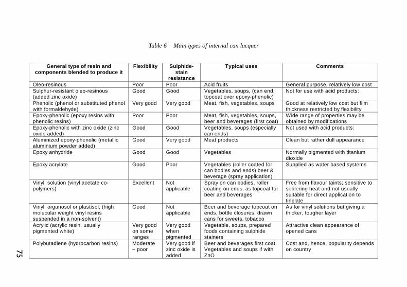
75
General type of resin and components blended to produce it
Flexibility Sulphide-stain
resistance
Typical uses Comments
Oleo-resinous Poor Poor Acid fruits General purpose, relatively low cost Sulphur-resistant oleo-resinous (added zinc oxide)
Good Good Vegetables, soups, (can end, topcoat over epoxy-phenolic)
Not for use with acid products:
Phenolic (phenol or substituted phenol with formaldehyde)
Very good Very good Meat, fish, vegetables, soups Good at relatively low cost but film thickness restricted by flexibility
Epoxy-phenolic (epoxy resins with phenolic resins)
Poor Poor Meat, fish, vegetables, soups, beer and beverages (first coat)
Wide range of properties may be obtained by modifications
Epoxy-phenolic with zinc oxide (zinc oxide added)
Good Good Vegetables, soups (especially can ends)
Not used with acid products:
Aluminized epoxy-phenolic (metallic aluminium powder added)
Good Very good Meat products Clean but rather dull appearance
Epoxy anhydride Good Good Vegetables Normally pigmented with titanium dioxide
Epoxy acrylate Good Poor Vegetables (roller coated for can bodies and ends) beer & beverage (spray application)
Supplied as water based systems
Vinyl, solution (vinyl acetate co-polymers)
Excellent Not applicable
Spray on can bodies, roller coating on ends, as topcoat for beer and beverages
Free from flavour taints; sensitive to soldering heat and not usually suitable for direct application to tinplate
Vinyl, organosol or plastisol, (high molecular weight vinyl resins suspended in a non-solvent)
Good Not applicable
Beer and beverage topcoat on ends, bottle closures, drawn cans for sweets, tobacco
As for vinyl solutions but giving a thicker, tougher layer
Acrylic (acrylic resin, usually pigmented white)
Very good on some ranges
Very good when pigmented
Vegetable, soups, prepared foods containing sulphide stainers
Attractive clean appearance of opened cans
Polybutadiene (hydrocarbon resins) Moderate – poor
Very good if zinc oxide is added
Beer and beverages first coat. Vegetables and soups if with ZnO
Cost and, hence, popularity depends on country
Table 6 Main types of internal can lacquer

76
requirements of the particular coating. Temperatures must be below the meltingpoint of tin, and for this reason a maximum of 205°C is normally never exceeded.Time at peak metal temperature is of the order of 10 minutes. At the exit ofthe stoving oven the cured sheets are stacked on pallets. They may requireseveral stages of lacquering and/or decorating, necessitating several stovingtreatments. Some plants have installed lines for continuous lacquering of tinplatecoil: on these high-speed lines the melting point of tin may be momentarilyexceeded.
The decoration of tinplate requires the printing of coloured designs on thesurface. Tinplate has an excellent surface for printing and in this respect issuperior to many high quality papers. However, there are certain fundamentaldifferences between printing on tinplate and printing on paper. In the first placetinplate is non-absorbent, so that ink or lacquer remains on the surface and hasto be dried by the application of heat or other form of energy. Secondly, themetal has a hard inflexible surface compared to paper, so that direct contactbetween printing plate and the tinplate surface is not practicable. Thirdly, interms of its spectral response, tinplate can be considered as being essentiallyblack: this means that if reproduction similar to that achieved on white paper isrequired, a white base must first be applied to the metal surface. However, forspecial decorative effects, use may be made of the surface appearance of thetinplate itself. Another important fact to be borne in mind is the functionalnature of the printed tinplate which is subsequently formed into various shapes,to be used as containers or other items. Coatings must remain adherent andundamaged even after forming operations which may involve quite severedeformation of the surface.
The tinplate surface makes possible a wide diversity of colour effects whenused in conjunction with the range of opaque and transparent printing inksavailable and the printing process itself has evolved to allow the preciseregistration of fine detail at high line speeds.
The decorating process consists of two operations; roller coating and printing.A number of coatings may be applied to tinplate before printing and a final over-varnish coating may also be applied after printing.
Printing on tinplate is not only for decorative purposes, but the creative andappealing design of a packaged product is vitally important for its sales potentialand this is especially true for the large range of foods, beverages and householdproducts marketed in cans. Although many food cans use separately appliedpaper labels, the use of labels printed directly onto the can is increasing and isalready universal for beer and beverage cans. Printed tinplate has a variety ofother uses including battery cases, trays, large container tins (for sweets, biscuits,etc.), bottle caps, ash-trays, and advertising signs.
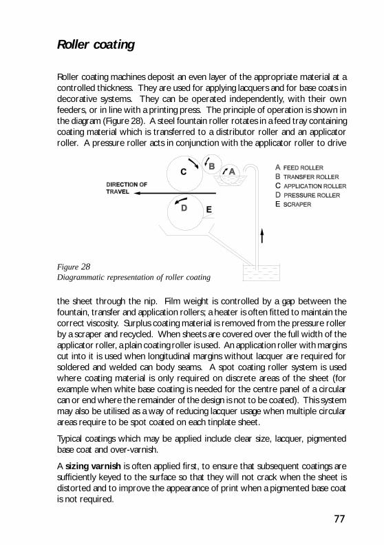
77
Figure 28Diagrammatic representation of roller coating
Roller coating
Roller coating machines deposit an even layer of the appropriate material at acontrolled thickness. They are used for applying lacquers and for base coats indecorative systems. They can be operated independently, with their ownfeeders, or in line with a printing press. The principle of operation is shown inthe diagram (Figure 28). A steel fountain roller rotates in a feed tray containingcoating material which is transferred to a distributor roller and an applicatorroller. A pressure roller acts in conjunction with the applicator roller to drive
the sheet through the nip. Film weight is controlled by a gap between thefountain, transfer and application rollers; a heater is often fitted to maintain thecorrect viscosity. Surplus coating material is removed from the pressure rollerby a scraper and recycled. When sheets are covered over the full width of theapplicator roller, a plain coating roller is used. An application roller with marginscut into it is used when longitudinal margins without lacquer are required forsoldered and welded can body seams. A spot coating roller system is usedwhere coating material is only required on discrete areas of the sheet (forexample when white base coating is needed for the centre panel of a circularcan or end where the remainder of the design is not to be coated). This systemmay also be utilised as a way of reducing lacquer usage when multiple circularareas require to be spot coated on each tinplate sheet.
Typical coatings which may be applied include clear size, lacquer, pigmentedbase coat and over-varnish.
A sizing varnish is often applied first, to ensure that subsequent coatings aresufficiently keyed to the surface so that they will not crack when the sheet isdistorted and to improve the appearance of print when a pigmented base coatis not required.

78
Lacquers are generally applied to one side of a sheet to form the internal surfaceof a container. However, lacquers are also used in printing to give a metallicexternal decorative effect (commonly gold) and may also be required for externalcorrosion protection. Lacquers are cured by stoving in the range 180 - 205°C,depending upon formulation.
Pigmented base coats consist of one or more pigments dispersed in an organicbase. When this is white, it provides a bright base for successive colours. Stovingtemperatures may be in a wide range up to about 160°C.
Over-varnish is applied as a final coating to protect the inks from scratchingduring tooling and subsequent handling and to provide lubrication to the surfacesduring forming processes. In addition to their toughness and tack-free curing,varnishes must also be able to withstand the stoving temperature (up to 170°C)without discolouring.
After each pass through the roller-coater, the tinplate sheets are picked up by aseries of closely-spaced racks (wickets) on an endless chain which hold them ina near vertical position and carry them through the curing oven. The ovens,which are usually gas-fired, direct blasts of hot air at the sheets and consist ofthree zones. In the first (come-up) zone, the sheets are raised to the stovingtemperature. In the second zone, they are held at this temperature for therequired time. In the final zone, the sheets are cooled sufficiently to be handledby automatic unloaders. As the sheets pass continuously through the oven, thisnecessitates the use of ovens 24-30 metres in length to accommodate throughputrates of 4000-7000 sheets per hour.
Photo-lithography
Flat tinplate sheet is printed by the photo-lithographic process. Lithographydepends upon the fact that some materials (e.g. copper) are receptive togreasy liquids such as printing ink, whilst others (e.g. chromium) are morereceptive to water (or water / alcohol mixture) and repel ink. Since grease andwater are immiscible, ink will not adhere to moist surface areas and will printselectively from grease receptive areas. Thus to apply a printed design bylithography, a printing plate must be produced, whose surface is composed ofgrease receptive areas carrying the design, surrounded by non-printing areaswhich are kept moist. As has been already stated, tinplate is too hard to print indirect contact with a printing plate, and the design is in fact “off-set” on to arubber covered blanket, which in turn contacts the tinplate, transferring thedesign onto the surface, and acting as a carrier of the design between plate andmetal sheet. This is known as “off-set lithography” and its introductionrevolutionised printing on tinplate.
79
In order to replicate the desired image on a printing plate, the original artworkis first photographed and reproduced as a series of transparencies, the size andnumber of which will depend on the complexity of the design. A simple blockof colour, for example, may be photographed as a continuous image which isthen reproduced as such on the printing plate; this is termed line printing. If theartwork has variations of light and shade or complex colouring (as in aphotograph) then the image is reproduced by “half-tone” printing where thevariations in intensity and colour are conveyed by breaking up the image into aseries of minute dots. The darkness or lightness is conveyed by the numberand size of the dots within a particular area. Colours in the original design arereproduced by printing a series of dot images, one for each of the componentcolours, as appropriate. Thus a full colour half-tone design may be reconstitutedby printing successive images in the three primary colours (yellow, cyan blue,magenta) plus black, using a separate printing plate for each colour. A designmay also incorporate a mixture of line and half-tone components.
For both monochrome and colour work, the half-tone dot pattern may beproduced by interposing a special magenta screen between the light source andthe film surface. For a colour design, a series of negatives is produced, one foreach printing colour, these colour separations being effected by the use ofappropriate filters when the design is photographed. It is now common to useelectronic scanning of artwork to carry out colour separation and densitydetermination. The artwork is mounted on a drum and scanned by a beam oflight which passes through one of a number of colour filters. Information on thevarious light intensities is transmitted to a computer which weighs and balancesthe signals so as to produce image transparencies with a precise colour separationand an accurate density reproduction. Printing plates are next prepared fromthe various component transparencies (either negatives or positives, dependingon the type of plate).
Plate production
The key to precise and accurate printing lies in the quality of the printing plate.A bi-metallic type of plate is sometimes still used, for example copper platedwith chromium in non-printing areas. The copper, initially plated all over withchromium, is coated by a specialised technique with a light-sensitive resin. Apositive of the required image is placed in contact with the light-sensitive surfaceand the plate is located in a vacuum frame and exposed to an ultra-violet lightsource. The exposed (i.e. non-printing) areas become hardened and resistantto the developer which is subsequently used to dissolve away the unexposedresin, revealing the chromium layer. The hardened resin now acts as an etchresist to the acid solution which is used to strip away the chromium, revealing

80
the underlying copper surface. Finally the hardened resin is removed using asuitable solvent, to leave the underlying chromium areas. This type of plate isvery durable and can be used for long printing runs of 100,000 sheets or more.
The most commonly used type of lithographic plate consists of anodisedaluminium coated with a special light-sensitive material. The plate is preparedby placing the image negative in contact with the coated side and exposing thesurface (under vacuum) to UV light which, as before, hardens the ink-receptiveexposed areas. The unexposed coating is subsequently washed off to revealthe underlying metal surface which does not print.
A variation on the above systems is the waterless plate, which has recentlybeen introduced into the tinplate printing industry. This reduces spoilage andset-up time, improves quality and gives a more consistent product. Instead ofrelying on the presence of water to reject the greasy ink the waterless plateemploys a silicone rubber surface to produce the same effect. The basic plateis made from thin aluminium and has both photo-sensitive and silicone rubbercoatings, which are selectively removed in the same way as the previouslydescribed plate systems. For this system to work satisfactorily, it is necessaryto control the temperature of the printing plate within the range 23 - 28°C.This is done by chilling the print roller with cold water or air. There is anenvironmental benefit with the use of the waterless plate as its use obviates theneed to employ alcohol as a damping agent.
It is often advantageous to produce multiple identical images on a printing plate.A “step and repeat” machine is used, in which the plate, clamped into a movableframe, executes a series of precise movements relative to the transparency andlight source. An exposure is made at each position and the plate is then developedin the normal manner.
Printing
General principles of the wet-lithographic offset printing unit are shown in thediagram (Figure 29). Three cylinders are involved, the plate cylinder aroundwhich is wrapped the metal printing plate, the blanket cylinder, which transfersthe design and which has either one or two rubber blankets tensioned aroundit, and the impression cylinder, which acts with the blanket cylinder to impartthe desired “nip” to the sheet. Inked and damping units are mounted over theplate cylinder, onto which the inking and damping rollers are lowered duringprinting to transfer water (or water / alcohol mix) and ink onto the printingplate, which in turn, transfers the image onto the blanket cylinder. The sheetpasses under pressure through the nip between blanket and impression cylinderand receives its impression. The impression and blanket cylinders are mounted

81
on eccentric bearings,enabling pressure to beapplied or withheld asdesired.
When waterless platesare used the generalprinciples of operationare the same as aboveexcept for the dampingcylinder, which is nolonger required.
Printing inks areintimate mixtures ofpigments, dyes, oils andvarnishes, and much ofthe improvedproductivity in printinghas been due toadvances in ink
Figure 29Representation of a typical roll arrangement forprinting on tinplate
formulation which allow faster running speed and curing. Special inks have alsobeen developed for particular applications such as outdoor signs (non-fading)and processed pack containers (resistant to prolonged heating in steam / watermixtures). Stoving takes place in ovens of the same type as those described forroller coatings at a temperature of about 130°C.
Until the 1950s, the single colour was almost exclusively used, and each coathad to be cured before application of the next. Since that time there has beencontinual development of both printing inks and machines such that four colourscan now be applied wet-on-wet in one in-line machine. Stoving then takesplace in ovens of the same type as those described for roller coatings. Some ofthe latest multi-colour printing machines are based on paper printing technology,permitting sheet thicknesses down to 0.10 mm to be handled at high speedwithout damage.
Ultra-violet curing
The introduction of inks and lacquers that may be cured by exposure for a fewseconds to UV radiation has had a major impact on the metal decorating industry.A photo-curable formulation typically contains a mixture of a low molecularweight unsaturated polymer (an acrylated polyester, acrylated epoxy or acrylatedpolyurethane) dissolved in a blend of reactive monomers such as acrylates or
B
C
sheet pass
E
D
A PLATE CYLINDER
B BLANKET CYLINDER
C IM PRESSION CYLINDER
D INKING UNIT
E DAM PING UNIT

82
methacrylates. Photo-initiators start a vinyl-type polymerisation reaction onexposure to UV radiation. Advantages include savings in energy consumption,less pollution from solvent fumes, faster curing and hence production rate andsavings in space. For multi-colour in-line printing, inter-deck UV curing ensureseach colour is fully cured before the next colour is applied.
Disadvantages at present include the expense of UV lamps and inks, the needfor a wider range of suitable inks and the need to meet legislation regardingsafety of UV inks for use with food and beverage cans. Also because of theextremely short curing time these inks are not so flexible as thermally curedinks. This may be important where deep forming of the tinplate takes placeafter printing (as in distortion printing work, which is described in the nextsection).
Considerable research is being undertaken into many aspects of the UV curingtechnology, including formulations, UV lamp characteristics, and the effect ofsubstrate.
Distortion printing
Before leaving the printing of flat sheets, the distortion printing technique shouldbe mentioned. This permits a design to be printed in the flat in such a way thatonly after forming the tinplate into a can shape does the printed design takes onits final intended appearance. This is achieved by first forming a sheet of tinplateprinted with a square grid pattern into the final article. The distortion undergoneby each particular area of sheet can then be evaluated accurately, allowing theinitial artwork to be modified to allow for the distortion effects. This process ofcalculating the amount of distortion to be built into the artwork is now largelydone by utilising computer techniques.
Coating formed two-piece drawn and wall ironed cans
For drawn and wall ironed food cans it is necessary to cover all of the outsidesurfaces with a polymer coating to give adequate corrosion protection andgood surface slip characteristics. This is achieved by placing the washed cans,with the base uppermost, on an endless stainless steel woven belt and thenpassing them through a series of falling curtains of water-based coating material.These ensure that the can external surfaces are completely covered with lacquer.The bulk of the lacquer then drains off to leave the correct film weight on thecans. The external coating is then cured by passing the cans through a gas firedtunnel oven.

83
For drawn and ironed beverage cans it is also necessary to apply an externalcoating. However in this case, as the side walls will be decorated by a protectiveprint / coating system, it is only necessary to apply a separate coating to thebase area. This may be done by either a roller coat or spraying process, inconjunction with the internal coating system described below.
For both drawn and wall ironed food and beverage cans it is necessary to applyan internal coating material to provide an inert barrier between the can and theproduct contained within. This is applied by an airless spraying process, thecans being spun at high speed during the spraying operation to ensure the coatingis evenly spread over the whole surface. Following this, the cans are placed,open end up, on an endless stainless steel wire mesh belt, which conveys thecans through a tunnel oven, to cure the internal coating. Depending on theproduct contained in the can, and specifically for beverage cans, it may benecessary to apply a second coat of internal lacquer and carry out another fullcuring operation.
Decorating formed two-piece cans
In the case of seamless two-piece cans, formed by drawing and ironing, thedegree of deformation is such that the tinplate cannot be printed beforehand.A non-lithographic “dry-offset” process is adopted in this case which has beenadapted from the technique widely used in the paper industry. The plate consistsof a photopolymer coating which is bonded to a steel backing by means of anadhesive. The plate is exposed to a negative, using ordinary fluorescent lightwhich hardens the exposed area. The unexposed areas are dissolved away byspraying the plate with alcohol, leaving behind the hardened portions in relief.Since the design is in raised relief on the plate, it can be coated with ink from aroller and will print directly on the offset blanket without the need for damping.
The first stage of the printing process may require the application of a backgroundcoating to form the main colour of the artwork. This can be applied directly tothe metal surface; no size need be used because the tinplate is quite clean andwill not undergo any appreciable further deformation. Each can is coated byrotating to complete one to two revolutions against a rubber roller, which iscontinuously inked by rotating in contact with a metal feeder drum. The cansare then off-loaded onto pins which carry them through a gas fired “pin oven”to dry the coating; up to 1500 cans per minute can be processed in this way.On emerging, the cans are taken off their pins by a magnetic belt which thenfeeds them into the conveyor system that carries them to the printing machine.
The printing machine consists of six separate printing heads arranged around alarge revolving drum, the latter carrying a greater number of offset blankets

84
Figure 30Diagram showing the principle of operation of a unit for printing on formed,cylindrical, can bodies
around its perimeter. Each printing head incorporates one component plate ofthe design so that a maximum of six colours may be applied over the base coat.As the drum rotates, the blankets contact each printing plate cylinder in turn,causing the complete artwork to be transferred to the blankets. Each blanketthen prints the complete image onto one can body as it passes the drum. Thearrangement is shown here diagrammatically (Figure 30). This printing systemis capable of high output, matching can-making speeds in excess of 1500 cans /minute.
After printing, a wet-on-wet overvarnish may be applied as the final operationbefore the cans are transferred to a “pin chain” which conveys them through a“pin oven”. where the complete decoration is cured. This may take, on average,just one minute at 170°C. However, some ovens are capable of an even fastercure and stoving time may be reduced to as little as six seconds. The neckingand spin-necking operations, which are done after all the internal and externalcoating and decoration has been completed, put great demands on the coatingmaterials, and it is often necessary to use coatings and inks specially developedfor this purpose.
Four printing plates
Cans
Drum with 6 offsetblankets
85
TINPLATE TESTING
The tests which may be applied to tinplate can broadly be classified into twogroups, objective, or quality tests and subjective, or performance tests. Manyof these tests, especially the former, are routinely carried out during manufacture,as part of a quality control programme. Other, more sophisticated tests areused for research purposes or to investigate problems which may have arisen inservice. The validity of any testing procedure is based on the assumption thatthe samples selected are representative of the bulk of the material to be tested.Sampling procedures for selecting sheets for mechanical property and coatingthickness tests are outlined in the international and national standards.
Mechanical property tests
A number of different mechanical properties may be determined for tinplate.No single mechanical test can measure all the factors which may determine itsperformance, nor is it possible to apply any single test satisfactorily to the rangeof tinplate products that is available on the market. The term “temper” whichis used to classify tinplate products, summarises a combination of interrelatedproperties. The performance of tinplate in processing and use is significantlydetermined by individual mechanical properties, which will vary on the steeltype, methods of casting, rolling, annealing, temper rolling employed.
The test considered to provide the best overall guide to mechanical propertiesis the tensile test. This test is often preferred as the referee method. For moreroutine testing, the Rockwell hardness testing method is used for single-reducedmaterial and the Springback test is used for double-reduced tinplate.
Other, more specific tests can be used to set additional demands on the formingproperties of tinplate.
The tensile test
The conventional tensile test provides the more accurate measure for the tensileproperties of tinplate, but is relatively slow and requires very careful skilledpreparation of the test specimens

86
The test consists of straining a specially prepared test piece, having parallelsides, by tensile stress, generally to fracture. As the tinplate is strained, itelongates, initially in proportion to the load applied. At a certain point (the limitof elasticity), the elongation proceeds more rapidly. The proof stress (Rp) isdefined as the stress at which a non-proportional elongation equal to a givenpercentage of the original gauge length occurs. For tinplate testing the valuecustomarily measured is 0.2% (Rp0.2). The tensile test is performed in the normalway, using wedge grips, but due to the light gauges commonly used for double-reduced tinplate, certain special precautions should be observed.
It is advisable to finish the preparation of the edges carefully with fine emerypaper, to remove any burrs.
The gauge length (effective length with parallel edges) used is 50 mm ± 0.5 mmand the width 12.5 mm ± 1 mm.
The rate of straining is usually 1 mm/min.
The grips employed should be capable of securing the sample such that noskew occurs during straining, to ensure that the applied stress is aligned centrallyalong the major axis of the test specimen.
The value recorded is the proof stress (Rp0.2).
Hardness
The Rockwell Superficial Hardness Test is used to assess single-reduced tinplatetemper grades; the hardness ranges specified for the various temper grades aregiven in Chapter Ill. This test is specified in international standards, normally onde-tinned specimens.
The Rockwell hardness tester is a direct reading instrument which measuresthe incremental depth of penetration of a ball indentor forced into the metal bya primary and a secondary load. In the Superficial Tester, as used for tinplate,the minor load is 3 kg and the major load a total of 30 kg or 15 kg. The loads areapplied via a system of levers and at a controlled rate. The hardness value isread directly on a calibrated dial.
To carry out the test, place the specimen on the diamond centre spot of theanvil, avoiding testing near the edges of the specimen because of a possiblecantilever effect. Bring the specimen into contact with the ball indentor byturning the hand wheel until the indicator on the dial shows that the minorload is applied. Then turn the adjustable rim of the dial until the pointer readszero, and apply the major load by operating the handle. The rate of loading iscontrolled by a dash-pot incorporated in the machine. As soon as the loading is

87
MANDREL
complete, remove the major load by pulling the handle forward and read theRockwell hardness number on the appropriate scale.
Due to the light gauge of tinplate sheet, the Rockwell 30T Hardness test issensitive to the “anvil” effect in which the measured apparent hardness is affectedby the thickness of the test specimen; for very thin sheet (e.g. < 0.20 mm.) a15 kg major load (15T Scale) may be used as described in the relevant standards.
Samples of continuously annealed material used for Rockwell hardness testingmust be adequately aged. Artificial ageing will normally be necessary where thematerial has not been pre-stoved through a lacquering or printing process.Artificial ageing can be achieved by heating the specimen to 200OC for 20minutes.
Other hardness tests used for sheet metal (e.g. Vickers) are not advised fortinplate testing since it is not possible to convert values accurately to Rockwellvalues.
The Springback test
The Springback test was devised to enable the proof stress of double reducedtinplate to be determined conveniently. It is frequently used as a routine testand is also cited in the appropriate standards.
Figure 31 Principle of operation of a springback tester

88
To perform the test, a tinplate specimen 150 mm x 25 mm wide, of knownthickness is clamped at one end and the free end is bent through 180 deg.around a 25 mm diameter mandrel with the aid of a forming roller pivoted so asto follow the mandrel (Figure 31). The free end of the specimen is then releasedand the springback angle read directly on the calibrated scale.
The amount of the springback angle and the thickness of the specimen are thenused to obtain the “springback index” in terms of the proof stress. Suitableconversion formulae are published for this purpose.
Formability tests
In addition to the tests which are stipulated in specifications, tinplatemanufacturers and users customarily carry out certain other tests on the steelbase to assess the suitability of the product for a given application. Amongthese tests are the following.
Fluting testIn the manufacture of three-piece cans the rectangular body blank is formedinto a cylindrical body. If the correct tinplate grade is not used the resultantcylinder will not be of smooth appearance, but the body wall will exhibit “flutes”or flat irregularities in its circumference. To check this the so-called fluting testis used.
In this test the specimen is simply formed into a cylinder of about 50mm diameterby a standard three-roll forming machine. After forming, the cylinder is examinedvisually for evidence of “flats” or irregularities in the circumference of the cylinder.This type of test is normally applied only to those grades of tinplate used forcircular bodies where fluting is undesirable.
Bend testsThe simplest form of bend test used for sheet metal is the single bend test inwhich a specimen is doubled on itself and hammered flat, to induce cracking.This type of test is not sufficiently sensitive for tinplate, all grades of which bendand seam readily. However, since in fabricating, for example a can body, sideseaming and end flanging involve bending the sheet both parallel and transverseto the rolling direction, it may be necessary to assess the degree of directionalityof its forming properties. This may be determined by an alternating bend testapplied to specimens cut along the rolling direction (“strong way”) and transverseto it (“weak way”).

89
The Jenkins alternating bend test
Figure 32 General view of the Jenkins bend tester
In this test a strip of tinplate, approximately 60 mm long by 12 mm wide isclamped between accurately radiused jaws and the free end is repeatedly bentto and fro through 180° until failure occurs. In the Jenkins machine the specimenis bent by a fixed diameter roller operated by a hand lever, the end point beingreached at the first sign of fracture through the specimen (Figure 32). Thenumber of full 180° bends required to produce the fracture is recorded as theJenkins Bend Value (the first half bend is ignored). It depends on the tempergrade and the sheet thickness.
When carrying out an alternating bend test, two specimens should always betaken, one cut with its long edges parallel to the rolling direction and the otherat right angles to this direction. The difference between the two Bend Valuesand the magnitude of the “weak way” value are both of significance and areparticularly useful in estimating bending and flanging properties.
Several more sophisticated machines for performing alternating bend tests havebeen devised on the same principle.
Cupping testsThe drawability of sheet metal is commonly assessed by means of cuppingtests. The principle underlying all cupping tests is that a cup is formed in thesheet specimen by means of a punch and die set mounted in a suitable press,the sheet being clamped by a pressure plate or mounting ring. The cupping

90
value is normally taken as the depth of impression required to produce fracture,although other criteria may be used, e.g. the drop in load on the punch whichoccurs at the moment of fracture.
Cupping test values are not normally included in tinplate specifications, but forroutine testing the test most frequently used for tinplate is the Erichsen cuppingtest.
Erichsen testIn the Erichsen test the test piece is a 76 mm diameter blank, held between anannular ring (blankholder) and the die; the punch is a 20 mm diameter hemisphereand it is advanced against the specimen mechanically or hydraulically to form adepression or “cup”. The end point is normally taken as the point at which thecup wall just fractures. The depth of impression, in millimetres, is the Erichsenvalue. It is related to the tinplate temper grade and the thickness of the material.
The Erichsen test method is defined in various national and internationalspecifications. For tinplate the standard method may be used except that,since tinplate carries an oil film, no additional lubrication is applied to the testspecimen.
Metallography
The steel base of tinplate may be examined by standard opticalmicro-examination procedures. Features of special interest are the shape andsize of the grain structure, to check the temper grade and the correctness ofthe annealing cycle; and the degree and distribution of non-metallic inclusions,which can affect formability.
Electron microscopy and scanning electron microscopy are widely used to studythe continuity of the alloy coating on tinplate.
Details of polishing and etching techniques for steel are beyond the scope ofthis booklet. They may be found in any standard metallographic textbook.
The coating of tinplate
The majority of tinplate is flow-melted, as described in Chapter II. The resultantcoating is therefore composite, comprising a thin layer of tin over an even thinnerlayer composed of the alloy FeSn2 formed by reaction between the electroplatedtin and the steel substrate. Each layer is metallurgically and tightly bonded tothe adjacent one.

91
The passivation treatment customarily applied to electrolytic tinplate, is intendedto convert part of the naturally occurring tin oxide film into a layer containingchromium and chromium oxides. This treatment is beneficial in improving bothstorage and lacquering performances. It is important to be able to characterisethe passivation films.
Both the tin coating of tinplate and the surface films, may be determined bycoulometric techniques. Before describing the details specific to a givendetermination, it is of interest to consider, in general terms, the principles ofthe coulometric technique.
Coulometric methods - general
Several of the laboratory inspection tests used for tinplate may be made bymeasurement of the charge passed in the performance of some particularoxidation or reduction. For this type of test, the basic equipment is always thesame: a source of controlled constant current, a suitable voltage recorder andan electrolysis cell which can contain the test sample, a counter-electrode, usuallyof platinum or carbon, and a reference electrode, usually silver/silver chlorideor saturated calomel. Modern equipment usually integrates the voltage sourceand measuring functions in a computer controlled unit, which also has data-handling, storage and output functions. The solutions used, the current densitiesand the direction of current, and the range of voltage to be measured differfrom test to test, but it is possible to use the same general equipment for varioustests. Therefore, a preliminary description of the basic apparatus is given nowso that it need not be repeated in dealing with the several tests for which it maybe used. It should be mentioned, that commercially available coulometricinstruments for coating thickness measurement, are usually not easily adaptableto other measurements. However, the electrolysis cell, one of the mostimportant parts of the apparatus, is often general purpose.

92
Electrolysis test cellFigure 33Diagram of simple cell forcoulometric measurements ontinplate.
The components are:A-test piece;B-O-ring;C-brass base;D-cell body, a cylinder oftransparent plastics material;E-counter electrode ofplatinum wire;F-tip of calomel referenceelectrode;G-inlet and outlet tubes forinert gas. Electricalconnection to the test piece ismade through the brass base.
The essential feature of the test cell is a holder for the test specimen which canmake a watertight joint around a precisely measured area of surface. This isaccomplished almost invariably by lining the edge of an aperture cut into plasticsmaterial with an O-ring or other form of gasket against which the test piece ispressed by tightening a screw thread, by a spring or by other means. A commonform of holder is a cylinder made of Perspex of length about 3 cm, with a circularaperture in one end and closed at the other end by a threaded plug whichpresses a tinplate disc of 5 cm diameter against a gasket surrounding the aperture.Electrical connection to the test specimen is by a light spring connected to awire passing through an insulated sleeve attached to the holder. A holder ofthis type is separate from the cell and must be held in place during tests, but hasthe advantage that electrolyte can be left in the cell between tests. However,many laboratories have preferred to use a cell in which the test specimen isexposed through an aperture at one end of the cell. This method has advantagesin that the position of the test specimen is always the same, that the cell can bemore easily closed for operation in oxygen-free conditions and that the testspecimen does not have to be cut to a precise shape or size to fit a holder. Acommon type of cell used has the test specimen covering an aperture in thebase of a cyclindrical cell closed at the upper end by a removable cap whichcarries the counter-electrode, the reference electrode and means for introducingnitrogen and test solution.
Cell bodies are made with several sizes of aperture ranging from 1 cm to 5 cmto permit tests on different areas. The use of small test areas, provided that

93
they are precisely limited by the cell aperture, has some advantages for surveyingvariations across a surface and for making measurements on manufactured canswhich have only small plane surfaces. The test specimen rests on a circularmetal plate by which it is pressed into contact with the cell base by an interlockingcollar engaging a flange on the base. A diagram of the cell is shown in Figure 35.Electrical connection to the test piece is made via the metal plate.
A general circuit diagram for the operation of several forms of coulometric testwith the basic equipment is shown in Figure 34.
Current source and measurementThe range of currents required for testing various properties over areas ofdifferent sizes is from 25µA to 200 mA. It is possible to cover this range with
Figure 34Circuit diagram for coulometric analysis
one of the constant voltage/current power sources availableready-made from laboratorysuppliers if the smaller constantcurrents are obtained by using aconstant high voltage of 100-200V with resistance of severalmegohms in series with the celland the larger currents are madeto rely on direct control of thecurrent by the source. If a generalduty source is not available, thesame plan can be followed usingsmoothed rectified mains voltageor a dry battery as a high voltagesource and batteries or other
convenient D.C. source with potential dividers to give the higher currents.
Potential measurementA potential recorder with a fast response and a chart speed of at least 30 mm/min is required and either the recorder must have the capability of showingchanges up to + 1 V from base-lines ranging from -1 to 0 V or means of applyinga controlled backing-off voltage must be provided. The recorder, if connecteddirectly to the electrodes must have an input impedance of more than 1 megohm:otherwise a voltmeter of high input impedance may be used and its readingsfed to a general-purpose recorder. An additional useful refinement is to obtainor make equipment which converts the signal to the recorder to the rate of

94
change of potential with time. Such a device produces a sharpened indicationof potential changes.
As mentioned, more modern potentiostats integrate the current source andmeasuring functions, together with the proper data-handling and analysingsoftware.
Tin coating mass determination
The free tin and the alloy layers may be determined separately or together. Forspecification purposes it is the total tin (i.e. free tin plus tin-in-alloy) which isdetermined. However, since certain characteristics, such as solderability orcorrosion resistance, may depend on the relative amounts of the two layers it iscustomary to determine them separately, by, for example, coulometrictechniques, and to sum the results.
Most standard specifications permit any of the recognised coating mass tests tobe employed as routine. Many fast and reliable methods can be used for routinemeasuring. Usually these methods give consistent results if used by the samelaboratory under steady conditions. For arbitration purposes, wet chemistryhas been proven to give the most certain results, so the Referee method (seelater) must be used.
The coulometric methodThis method is widely used for the determination of both free tin and tin-in-alloy.The principle of the method is that the coating is dissolved by the action of ananodic current in hydrochloric acid and the time intervals required for dissolutionof the free tin layer of the coating and of the alloy layer are indicated by changesof potential between the test piece and a reference electrode. Usually thecurrent density on the test-piece is held constant and the charge required toremove a layer of the coating is obtained by multiplying the value of the currentby the time taken for dissolution of the layer. It is possible to measure thecharge directly with a wattmeter with automatic or manual separation of readingsfor the two layers; in this instance exact control of the current is unnecessary.
The apparatus required is that described for general coulometric methods.Current densities in the range 4-10 mA/cm2 are required. The referenceelectrode may be a silver rod or saturated calomel.
The solution used is 1.0 M hydrochloric acid. The solution may be used manytimes, perhaps 10-50 depending on the cell capacity. It should be changed afterit has stood idle for some hours or whenever potential measurements indicatedeterioration.

95
For research purposes, when precise measurements of potential andcurve-shapes may be required, a fresh solution should be used for eachdetermination.
ProcedureWhen the apparatus is first set up, and occasionally thereafter, make a dummyrun with known material to establish that controls of current and the recordingof the potential are satisfactorily established. The current density may rangefrom 4-10 mA/cm2 and a value at the upper end of this range is usually suitable.The potential measured will be negative to the reference electrode and thechange from the start of stripping the free tin layer to the final exposure of steelwill be about 180 mV. Whether the apparatus is automatically or manuallycontrolled, it is wise to check occasionally the calculated coating mass againstreliable direct measurements for each layer of the coating. Attention shouldalso be paid to the uniformity of removal of the coating over the tested area,and, if necessary, the position of the cathode should be adjusted.
Cut a test piece of the shape and size appropriate to the cell used and clean itcathodically in 1% sodium carbonate solution at room temperature. Place thecleaned test piece in position in the cell together with the counter-electrodeand reference electrode. Introduce sufficient solution to cover the test areaand the electrodes and immediately start the potential recorder and switch onthe current. When coating removal is complete switch off current, remove thetest piece and examine the surface for any evidence of incomplete ornon-uniform stripping.
(The sequence described for placing specimen and electrodes and for introducingsolutions are those suitable for the type of cell in which the specimen is heldagainst an aperture in the cell body; the operations will be different when thespecimen is held in a removable holder and the solution remains in the cellbetween tests.)
ResultsA typical potential time curve is shown in Figure 35 together with a plot of therate of change of potential against time. The ideal end points for dissolution ofthe free tin layer and of the alloy layer are the points of inflection before thechange to the next potential step. The point of inflection is usually easilyperceptible in the potential/time trace and is made sharply apparent by thedifferential curve which may be obtained automatically by suitable analysingsoftware. ASTM A630-68 uses intersections of extensions of the lines of thepotential steps with lines following the maximum slope during the major potential
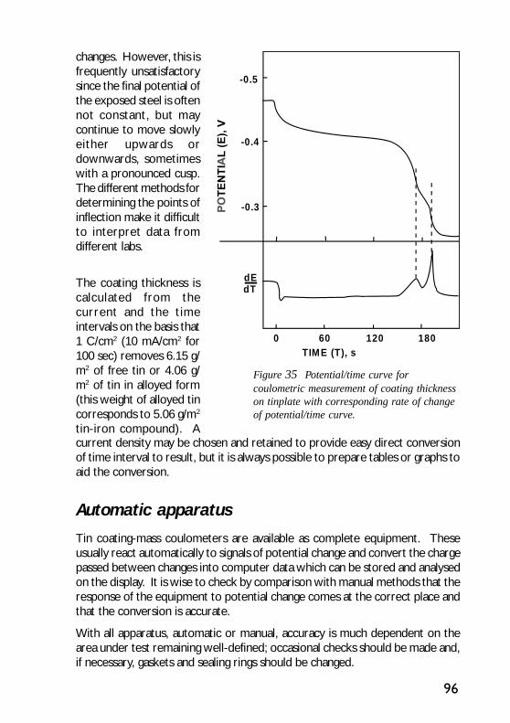
96
changes. However, this isfrequently unsatisfactorysince the final potential ofthe exposed steel is oftennot constant, but maycontinue to move slowlyeither upwards ordownwards, sometimeswith a pronounced cusp.The different methods fordetermining the points ofinflection make it difficultto interpret data fromdifferent labs.
The coating thickness iscalculated from thecurrent and the timeintervals on the basis that1 C/cm2 (10 mA/cm2 for100 sec) removes 6.15 g/m2 of free tin or 4.06 g/m2 of tin in alloyed form(this weight of alloyed tincorresponds to 5.06 g/m2
tin-iron compound). A
Figure 35 Potential/time curve forcoulometric measurement of coating thicknesson tinplate with corresponding rate of changeof potential/time curve.
current density may be chosen and retained to provide easy direct conversionof time interval to result, but it is always possible to prepare tables or graphs toaid the conversion.
Automatic apparatus
Tin coating-mass coulometers are available as complete equipment. Theseusually react automatically to signals of potential change and convert the chargepassed between changes into computer data which can be stored and analysedon the display. It is wise to check by comparison with manual methods that theresponse of the equipment to potential change comes at the correct place andthat the conversion is accurate.
With all apparatus, automatic or manual, accuracy is much dependent on thearea under test remaining well-defined; occasional checks should be made and,if necessary, gaskets and sealing rings should be changed.
120 180600TIME (T), s
-0.3
-0.4
-0.5
dEdT

97
X-ray fluorescence technique
In the X-ray fluorescence method, the sample of tinplate is irradiated with X-rayswhich penetrate the tin coating and excite fluorescent secondary radiation onthe steel surface. The intensity of the emergent fluorescent beam depends onthe thickness of the coating through which it passes and measurement by meansof a suitable counter enables a rapid and nondestructive means of thicknessdetermination.
There are several commercial examples of apparatus using this principle. As anon-destructive test it may be used as a laboratory tool for monitoring thecoating mass on individual sheets at localised areas. The technique has alsobeen adapted for in-line monitoring of coating thickness in electrolytic tinplatelines. In this form the apparatus customarily travels systematically across thestrip width and monitors at frequent intervals the coating at selected points.
The Referee method
National and international standards specify a Referee method to be used incases of dispute. In most standards it is a volumetric method, which involvesdissolution of the tin coating in hydrochloric acid. The tin in solution is reducedto the tin (II) form with pure aluminium wire, and determined by titration withstandard potassium iodate-iodide solution under an atmosphere of carbondioxide. The effective range of the method is from 2.5 g/m2 up to 50 g/m2, thereproducibility being ± 0.1 g/m2. Other (proposed) standards specify thepreviously described coulometric method as the referee method.
The detailed procedure is fully described in various national and internationalstandards to which reference should be made. A summary of the volumetricmethod is as follows.
From each of the selected sheets, accurately punch three specimens each of anarea not less than 25 cm2, one from the centre of the sheet and the other twofrom diagonally opposed corners. Degrease these specimens with ether. Forma flat spiral of two turns and approx. 12.5cm diameter from a length of about75cm of platinum wire of 0.6mm diameter and place centrally in a shallow dish.Place six of the discs in a circle on the platinum wire and pour 150ml ofhydrochloric acid (750g/l prepared by diluting 750ml of the concentrated acid(d 1.16) to 1 litre with water) into the dish. When the tin coating is dissolved(3-15 min according to its thickness) transfer the acid to a 1 litre volumetricflask, wash twice with 25ml of water, transferring the washings to the flask.Repeat the procedure with successive lots of six discs, combining the acid andwashings in the same flask and finally diluting to the mark with water.

98
Transfer a 100 ml aliquot of the solution to a 750 ml conical flask, add 30 ml ofhydrochloric acid (d. 1.16), dilute to 250 ml and heat to nearly boiling. Add 2g of aluminium (99.5%, tin free, and in the form of heavy foil, coarse millings ordrillings) in small amounts, and before complete dissolution of the last additionof aluminium, close the flask with a Contat-Göckel trap filled with a saturatedsolution of sodium hydrogen carbonate. Boil gently for 30 min to redissolve theprecipitated tin metal, cool slightly and close the outer tube with a rubber cap.Cool in running water to room temperature (20°C), remove the trap, add 5 mlof a 1% starch solution and 10 ml of a 10% potassium iodide solution andtitrate with standard potassium iodate solution to a permanent blue colour.
The procedure differs slightly depending on whether electrolytic, differential,or hot dipped tinplate is to be determined. Thus for equally coated electrolytictinplate, 12 specimens from four sheets are taken and the standard potassiumiodate solution is 0.05 N* (1.7835 g/l; 1 ml ≡ 0.0029675 g Sn). For differentiallycoated tinplate, a similar 12 specimens are taken, but each surface coating isdetermined separately, the alternate side being masked with a suitable lacquer.The alternate face is subsequently determined, using the same (delacquered)specimens. The standard potassium iodate solution is 0.025 N* (0.8918 g/l;1ml ≡ 0.00148375 g Sn).
The average coating mass is given by the expression,
where:V = volume of potassium iodate in mlN = normality of the potassium iodate solutionA = total specimen area in cm2
*The term “normality” rather than “molarity” is used with regard to the strengthof the KI03 solution because this, together with the factor for tin (1 mI of 0.1NKI03 ≡ 0.005935 mg Sn) indicates to the analyst the reaction being used in thistitration.
The Bendix method
(Ind. Eng. Chem. (Anal. Edn.) 1943, 15, 501).
This procedure may be used as a reasonably rapid test to check the validity oftests such as the X-ray fluorescence method, or where complex instrumentationis not available.
A
VNmgmasscoatingTin
32 10935.5)/(
×=
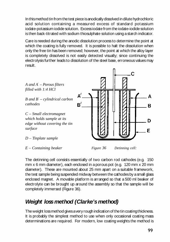
99
In this method tin from the test piece is anodically dissolved in dilute hydrochloricacid solution containing a measured excess of standard potassiumiodate-potassium iodide solution. Excess iodate from the iodate-iodide solutionis then back-titrated with sodium thiosulphate solution using a starch indicator.
Care is needed during the anodic dissolution process to determine the point atwhich the coating is fully removed. It is possible to halt the dissolution whenonly the free tin has been removed; however, the point at which the alloy layeris completely dissolved is not easily detected visually; since continuing theelectrolysis further leads to dissolution of the steel base, erroneous values mayresult.
A and A’ – Porous filtersfilled with 1:4 HCl
B and B’ – cylindrical carboncathodes
C – Small electromagnetwhich holds sample at itsedge without covering the tinsurface
D – Tinplate sample
E – Containing beaker
The detinning cell consists essentially of two carbon rod cathodes (e.g. 150mm x 6 mm diameter), each enclosed in a porous pot (e.g. 120 mm x 20 mmdiameter). These are mounted about 25 mm apart on a suitable framework,the test sample being suspended midway between the cathodes by a small glassenclosed magnet. A movable platform is arranged so that a 500 ml beaker ofelectrolyte can be brought up around the assembly so that the sample will becompletely immersed (Figure 36).
Weight loss method (Clarke’s method)
The weight loss method gives a very rough indication of the tin coating thickness.It is probably the simplest method to use when only occasional coating massdeterminations are required. For modern, low coating weights the method is
Figure 36 Detinning cell:
100
not suited. However, dissolving the tin coating in Clarke’s solution provides auseful practice to obtain the uncoated product. In this direct method, an additionof antimony to hydrochloric acid is used for the dual purpose of acceleratingthe dissolution of tin and of inhibiting dissolution of the steel base.
A sample of convenient size, say 50-100 cm2 is degreased, dried and weighed.It is then immersed in 100 ml of HCl containing 2 g Sb203 and allowed to remainin the stripping solution for about 1 minute after gas evolution has ceased. It isthen washed, the black deposit of antimony removed by swabbing with cottonwool, dried and re-weighed. The weight loss represents the sum of the free tinand the alloy layer, so that a correction is needed for the amount of iron in thealloy layer, though for electrolytic tinplate this correction may usually beneglected. For hot dipped tinplate the correction is about 1.4 g/m2 and forelectrolytic tinplate about 0.4 g/m2. If considered necessary the correction maybe found from a determination of the alloy layer.
Assessment of tin oxide film
Tinplate surfaces are always to some extent covered by tin oxide which maycontain one or both of stannous and stannic oxide together with their hydratedforms. Electrolytic tinplate, cathodically passivated, should have, immediatelyafter treatment, only a very small amount of tin oxide on the surface and themeasurement of this oxide may give some indication of the effectiveness of thetreatment. A non uniform treatment or an over-long passage through thedichromate solution after the cathodic treatment section may produceabnormally high oxide. Although tin oxide may be measured on newly producedtinplate to help to check departures from correct procedure, the formation ofadded oxide during storage is most likely to cause troubles with appearance,lacquerability and solderability. Tin oxide measurements are therefore rathermore valuable to users than to producers. Part of the object of passivationtreatments is to prevent or restrict tin oxide growth and assessment of thepassivation film itself, by chromium determination or resistance to heatdiscoloration, is a more useful means of assessing future behaviour thanmeasurement of the initial tin oxide.
Positive identification of particular oxides is only possible by electron or X-raydiffraction and not always by these means, but it is more useful to have a measureof the quantity with some indication of the nature and the simpler means ofcontrolled cathodic reduction can provide this information.

101
Coulometric method
PrincipleTin oxide is reduced by a controlled small cathodic current in a solution freefrom oxygen and inert to tin oxides. The progress of reduction of the oxide isfollowed by potential measurement and the charge passed for the completereduction serves as a measure of the tin oxide on the surface.
ApparatusThe equipment is that described for general coulometric measurements withtinplate but provision must be made for removal of oxygen from the test celland for the introduction into the cell of oxygen-free solution. With the type ofcell described earlier, for coulometric measurements, the closure to the top ofthe cell is fitted with an exit and entry tube, through which nitrogen passesafter bubbling through the test solution contained in a suitable flask.
Solution0.001N hydrobromic acid, freed from oxygen by, for example, boiling and coolingwhilst scrubbed with nitrogen. This solution is widely used for routinemeasurements and gives reliable results but other solutions may be used forresearch purposes, for example, a sodium phosphate solution buffered to nearneutrality.
ProcedureWhen the apparatus is first set up, it is useful to carry out a dummy run with anoxidised tin surface to ensure that the current and potential range are correctlyset. The directions given are those applying to the cell previously described,but the necessary modifications for any other form of cell should be clear. Aconvenient current density is 25 µA/cm2 and the potential range to be recordedwill usually be 400-1000 mV negative to a calomel electrode.
Rinse the test piece with a neutral solvent and place it in the dry test cell.Close the cell and pass through it a stream of nitrogen which has alreadybubbled through the test solution contained in a flask joined to the cell by aflexible tube. After two minutes, invert the flask containing the solution so thata quantity sufficient to cover the test piece and electrodes is forced into thetest cell. The delivery tube should remain above the surface of the solution andshould be partly withdrawn if too much is delivered. Switch on the recorderand then the current with the test piece as cathode. Record the potential until
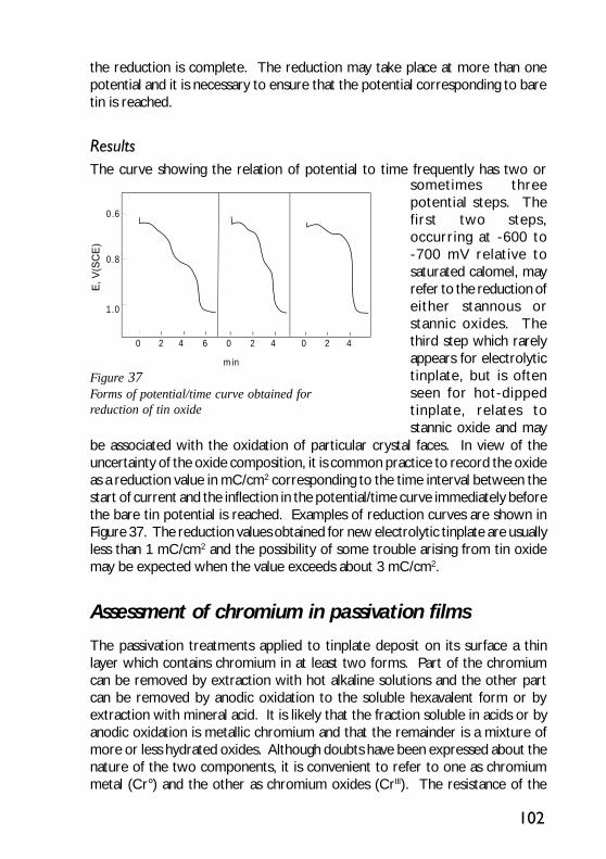
102
the reduction is complete. The reduction may take place at more than onepotential and it is necessary to ensure that the potential corresponding to baretin is reached.
ResultsThe curve showing the relation of potential to time frequently has two or
Figure 37Forms of potential/time curve obtained forreduction of tin oxide
sometimes threepotential steps. Thefirst two steps,occurring at -600 to-700 mV relative tosaturated calomel, mayrefer to the reduction ofeither stannous orstannic oxides. Thethird step which rarelyappears for electrolytictinplate, but is oftenseen for hot-dippedtinplate, relates tostannic oxide and may
be associated with the oxidation of particular crystal faces. In view of theuncertainty of the oxide composition, it is common practice to record the oxideas a reduction value in mC/cm2 corresponding to the time interval between thestart of current and the inflection in the potential/time curve immediately beforethe bare tin potential is reached. Examples of reduction curves are shown inFigure 37. The reduction values obtained for new electrolytic tinplate are usuallyless than 1 mC/cm2 and the possibility of some trouble arising from tin oxidemay be expected when the value exceeds about 3 mC/cm2.
Assessment of chromium in passivation films
The passivation treatments applied to tinplate deposit on its surface a thinlayer which contains chromium in at least two forms. Part of the chromiumcan be removed by extraction with hot alkaline solutions and the other partcan be removed by anodic oxidation to the soluble hexavalent form or byextraction with mineral acid. It is likely that the fraction soluble in acids or byanodic oxidation is metallic chromium and that the remainder is a mixture ofmore or less hydrated oxides. Although doubts have been expressed about thenature of the two components, it is convenient to refer to one as chromiummetal (Cr°) and the other as chromium oxides (CrIIl). The resistance of the
0 2 42 404 6
m in
0 2
1.0
0.8
0.6
103
tinplate to sulphur staining benefits more from the presence of Cr° than fromthe presence of CrIIl and there is therefore some interest in measuring the twocomponents separately. However, the tinplate produced on one line with thesame passivation conditions maintains a nearly constant ratio of the amounts ofthe two components and this same relationship may hold good for a number ofother lines also operating a similar cathodic passivation process.
It is therefore possible to obtain a good approximation to the total amount ofchromium on the surface by measuring only the component which may beoxidised anodically and this measurement may be made rapidly by coulometry.The coulometric method is suitable for most routine checks of production or ofsuitability for particular purposes but it will not yield information about theseparate components. Other tests for determining the chromium on tinplateare by direct dissolution in sulphuric acid and determining the chromium contentsby means of Atomic Absorption Spectrometry or by the chemicaldiphenylcarbazide method.
Coulometric method
PrincipleOne of the components of the passivation film and a small fraction of another isoxidised by anodic applied current to soluble hexavalent chromium. Becauseother oxidation processes are taking place, the theoretical yield from the chargepassed on oxidation from CrO to CrVI is not obtained but a calibration madeagainst chemical analysis holds good for a wide range of tinplates.
ApparatusThe general purpose coulometric apparatus may be used. Special requirementsare that any reference electrode must not leak chloride appreciably into thetest solution, although a saturated calomel electrode with one of the betterwick-sealed capillaries on its sheath is satisfactory, and that the potential measurershall be capable of covering a range up to +2000 mV.
SolutionA phosphate buffer of pH 7.4 is suitable and may be prepared by mixing 200 mlof a sodium dihydrogen phosphate solution, 8 g/l, with 800 ml disodium hydrogenphosphate solution, 9.5 g/l. Other solutions may be used but the pH should bebetween 6 and 8.5 and the calibration should be made for the solution that is tobe used.
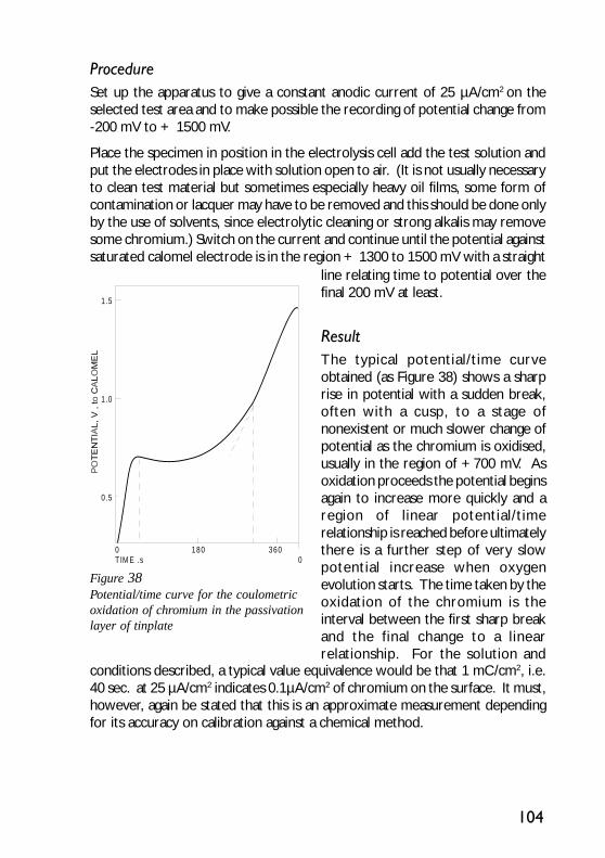
104
ProcedureSet up the apparatus to give a constant anodic current of 25 µA/cm2 on theselected test area and to make possible the recording of potential change from-200 mV to + 1500 mV.
Place the specimen in position in the electrolysis cell add the test solution andput the electrodes in place with solution open to air. (It is not usually necessaryto clean test material but sometimes especially heavy oil films, some form ofcontamination or lacquer may have to be removed and this should be done onlyby the use of solvents, since electrolytic cleaning or strong alkalis may removesome chromium.) Switch on the current and continue until the potential againstsaturated calomel electrode is in the region + 1300 to 1500 mV with a straight
Figure 38Potential/time curve for the coulometricoxidation of chromium in the passivationlayer of tinplate
line relating time to potential over thefinal 200 mV at least.
ResultThe typical potential/time curveobtained (as Figure 38) shows a sharprise in potential with a sudden break,often with a cusp, to a stage ofnonexistent or much slower change ofpotential as the chromium is oxidised,usually in the region of +700 mV. Asoxidation proceeds the potential beginsagain to increase more quickly and aregion of linear potential/timerelationship is reached before ultimatelythere is a further step of very slowpotential increase when oxygenevolution starts. The time taken by theoxidation of the chromium is theinterval between the first sharp breakand the final change to a linearrelationship. For the solution and
conditions described, a typical value equivalence would be that 1 mC/cm2, i.e.40 sec. at 25 µA/cm2 indicates 0.1µA/cm2 of chromium on the surface. It must,however, again be stated that this is an approximate measurement dependingfor its accuracy on calibration against a chemical method.
0 180 3600T IM E .s
0 .5
1 .0
1 .5
105
Diphenylcarbazide methodThe chromium on tinplate may also be determined by a chemical method. Thediphenylcarbazide method is described in detail in the American SpecificationASTM A623:98. For completeness, brief details of the method are given below.
A sample disc having a diameter of 5.75 cm is used. This provides a surface areaon each face of 26 cm2. (Total surface 52 cm2.)
Place the sample in a beaker, with 25 ml of a mixed sodium hydroxide, trisodiumphosphate solution (1 N NaOH, 5% Na3PO4,) and boil for about 1½ min.Transfer the alkaline solution to a fresh vessel. To the original beaker and sample,add 25 ml H2SO4, (25% solution by vol.) and boil again. Combine the twosolutions again, bring to boiling point and add 1-2 drops KMn04 solution toproduce a pink colour. Boil to oxidise the chrome (usually 3-4 min). Add 5drops HCl (SG 1.19) and continue to boil until pink colour disappears.
Transfer to a 100 ml volumetric flask, cool to approximately 21°C. Add 3 mldiphenylcarbazide reagent, make up to the mark with water.
Determine the optical density at 540 nm. The ASTM recommends carrying outthe tests in conjunction with reagent blanks and a standard using all solutionsemployed. The spectrophotometer is calibrated against standard K2Cr2O7,solutions.
ASTM A623:98 also includes formulae for the calculation of the amount ofchromium on tinplate in terms of micrograms chromium per square foot ofsurface:
Calibration of spectrophotometer:
Calculate a constant, K for the instrument as follows:
K = (µg Cr) / (O.D.1 - O.D.2)
Where:O.D.1 = optical density for the standard, and
O.D.2 = optical density for the blank.
Calculation of chromium on tinplate:
Report chromium on tinplate as micrograms of chromium per square foot ofsurface area, as follows:
Cr, µg/ft2 = [144 K (O.D.1 - O.D.2)) /A

106
Where:K = constant for spectrophotometer and cell used to determine opticaldensity
O.D.1 = optical density of sample
O.D.2 = optical density of reagent blank, and
A = area of sample used in ft2.
Special property tests
This group of tests has been designed to assess characteristics that influencethe shelf lives of citrus fruit packs in plain cans. Special property test values arenot normally specified in national or international standards, although detailedprocedures are described in ASTM A623. These properties are only specifiedand tested in very specific purposes. In this overview only a rough descriptionis given. More specific details can be found in the standard given above.
The alloy tin couple (ATC) test
The ATC test is designed to measure certain characteristics of electrolytic tinplateaffecting internal can corrosion resistance. The test is applicable to tinplatehaving a nominal coating mass 5.6/2.8 g/m2 or heavier. It is not applicable to2.8/2.8 g/m2 or lighter coated tinplate.
The ATC test is an electrochemical procedure which involves measuring thecurrent flowing between a pure tin electrode and an FeSn2 electrode, preparedby removing the free tin from a specimen of tinplate so as to expose the alloylayer. The current measurement is made after 20 hours exposure of theelectrodes in an electrolyte comprising de-aerated grapefruit juice.
A serious drawback to the test is its dependence on a natural medium. However,synthetic electrolytes not only give numerically different results, but also mayput a range of tinplates into a different order of merit.
The aerated medium polarisation (AMP) test
One disadvantage of the ATC test is the considerable time (20 hr) taken toobtain results. The AMP test has been developed which can give a rough guidewithin a matter of minutes.
In this test, a specimen prepared as for the ATC test is cathodically polarised athigh current density, the high polarisation current serving to remove oxygen

107
from the grapefruit juice medium near the surface of the electrode. For a givencurrent density, the polarisation (change in potential after current is switchedon) depends on the proportion of steel exposed, as steel is less strongly polarisedthan iron-tin alloy.
The AMP value may then be converted to an “ATC value” using calibrationcurves prepared by running the two tests with the same material but it shouldbe emphasised that “ATC values” obtained in this way have no validity on theirown account, being merely rapid estimates of what the true ATC value mayturn out to be.
Iron solution value (ISV) test
Like the ATC (and AMP) tests, the ISV test is only applicable to the heaviercoated tinplate grades. The ISV test involves the colorimetric determination ofthe iron dissolved when a controlled area of tinplate is exposed for two hoursat 27°C to 50 ml of a solution that is a mixture of dilute sulphuric acid, hydrogenperoxide and ammonium thiocyanate. The ISV is defined as the number ofmicrograms of iron dissolved.
The pickle lag test
The pickle lag test (also referred to as Rate of Pickling Test or Induction PeriodTest), is a test performed on the steel base of tinplate (i.e. on detinned material).Nonetheless as for the other special property tests, the test results should notbe considered to be significant for the lower coating mass tinplates.
Tin crystal size (TCS) test
For some purposes it may be desirable to measure the grain size of the free tinsurface (TCS). This is readily done by lightly etching the surface with a suitableetchant and comparing the grain size against standard grain size charts (ASTM),a useful predictor of tinplate performance. A suitable etchant contains in onelitre, 84 ml concentrated hydrochloric acid, 100 g hydrated iron (III) chlorideand 0.5-1.0 g sodium sulphide or sodium bisulphite. Although the solution isreusable, it should be replaced when etching of a correctly prepared specimentakes longer than 30 seconds or when the solution turns green.
Samples of about 25 cm2 area are taken, identification marks being put on theface opposite to that to be tested. Samples are cleaned cathodically in 0.5-1%sodium carbonate solution for 15-30 seconds at room temperature, rinsed anddried. The cleaned samples are then dipped into the etching solution until the
108
grain pattern can just be seen (usually 5-15 seconds), withdrawn, rinsedthoroughly in water and dried. The tin crystal size, as viewed with the unaidedeye is compared directly with the ASTM macro grain size number standards(test method ASTM E112). The result is usually expressed as a grade numberon the ASTM chart, and for tinplate a typical number is in the range 6 to 12.
Porosity tests
In general, the porosity of a plated coating is inversely related to its thickness.However, for comparison purposes it is sometimes desirable to assign a numericalvalue to, or to assess visually, the porosity of a given sample of tinplate. Thereare many suitable tests, among them the following.
Thiocyanate test
The test sample is immersed in an acid solution containing ammonium thiocyanatedesigned to be inert to tin but aggressive to steel exposed at coating pores.The amount of iron entering solution is estimated colorimetrically as iron (III)thiocyanate.
Scratch-free tinplate samples, say 100 mm by 50 mm in area, are selected to berepresentative of the undamaged surface. The samples are first cleaned by acathodic-anodic-cathodic treatment in 1% sodium carbonate solution at roomtemperature. This treatment removes deposits introduced into pores by thepassivation treatment. After rinsing and drying, cut edges of the sample shouldbe coated with wax or lacquer. The sample supported by non-metallic material,should then be immersed in the test solution (250 ml) left undisturbed for 15minutes then moved briskly in the solution and removed. The test solutionconsists of 100 ml thiocyanate solution (50 g of ammonium thiocyanate in 1 litreof water), 100 ml acetic acid solution (25 g acetic acid per litre of water) and 50ml hydrogen peroxide solution (3 g hydrogen peroxide per litre of water). Afterremoval of the sample, add 5 ml of dilute sulphuric acid (400 ml concentratedsulphuric acid in 1 litre of water) and compare the intensity of the red colourwith that produced by standard solutions. The results of the thiocyanate testare normally expressed as mg Fe/dm2 of surface.
Sulphur dioxide test
The sample is exposed for a fixed period to an atmosphere containing a smallamount of sulphur dioxide. Under these conditions, rust spots form at pores,whereas areas of continuous tin coating are unaffected.
109
The test sample is first cleaned cathodically-anodically-cathodically in 1% sodiumcarbonate solution, as for the thiocyanate test, and then well rinsed (in water,followed by acetone or ethanol) and dried.
Test samples are suspended, by means of glass hooks hanging from a plasticframe, within a vessel fitted with an airtight closure. The vessel contains avolume of sodium thiosulphate solution (10 g sodium thiosulphate per litrewater) equal to 1/20th of the vessel’s capacity, to which has been added 0.1 Nsulphuric acid (4.9 g/l H2SO4) in the ratio 1 part acid for every 10 partsthiosulphate solution. The ambient temperature is maintained at 23±3°C. Thesamples are suspended in such a way that no part of their surface will be morethan 300 mm or less than 100 mm from the surface of the solution, makingsure that each specimen is separated from its neighbours or the wall of thevessel by at least 20 mm. After adding the sulphuric acid, the specimens aresuspended in position within 5 minutes, the vessel is then closed and leftundisturbed for a suitable period. Usually 16-24 hours is sufficient to allow rustto develop at all pores, if longer periods are employed, spread of rust mayobscure single pore sites. At the end of the test period, the test samples areremoved and inspected.
They may be compared with previously prepared reference samples;alternatively a pore count may be made. Because pore densities may be of theorder of 1000/cm2, it may be impracticable to count each pore separately; thesurface may be covered by a grid marked in 0.5 cm squares, and the porescounted at a magnification of x5 on a number of squares distributed at randomover the test area.
The sulphur dioxide test can also be used as a direct measure of the corrosionresistance of passivated tinplate. In this case, the test pieces are not cleanedbefore exposure, and the exposed samples are compared with referencestandards. Surface heterogeneity revealed in this way can be of value in indicatingdefects in the steel substrate or variations in the passivation or oil films.
Sulphide stain resistance
One of the functions of surface chromium metal in passivation films is to protectagainst the formation of unsightly tin sulphide deposits that may form duringthe heat processing of canned meats or other sulphur-containing foods. Surfacechromium content is one useful guide to the likely resistance to sulphide staining(about 1 µg chromium/cm2 being needed for good resistance); another directmeasure of sulphide stain resistance is the cysteine staining test. Cysteine is asulphur-containing amino acid, present in some natural products, and the testinvolves exposure of samples to neutralised cysteine solution at 110°C for 30
110
minutes under pressure. The test solution consists of cysteine hydrochloridesolution (3g per litre in distilled water of low oxygen content) neutralised topH7 by addition of 0.2 M trisodium phosphate. The test is carried out infruit-preserving jars within a pressure vessel. The test-pieces are circular 50mm diameter discs or squares of side 40 mm with central holes to accommodate2-3 mm diameter glass rods. Spools of samples are prepared by threading thediscs on glass rods that are expanded at one end and slipping 15 mm long lengthsof tubing after each sample to act as spacers. Blank specimens are fitted toeach end of each rod.
The jars and pressure vessel are heated to 100°C, the cysteine solution, justneutralised, being brought to the boil in a separate beaker. A spool of samplesis placed in a jar which is then flushed through with nitrogen. The hot cysteinesolution is poured into the jar which is quickly transferred to the pressure vesselfull of boiling water. When all the jars for the test are in place, the pressurevessel is closed and, after venting of air, its temperature is raised to 110°C, thistemperature being maintained for 30 minutes. After releasing the pressure, thevessel is opened, the jars removed and allowed to cool. When cool enough,test samples are removed, rinsed with hot water, dried and inspected. Thesample may either be compared with a set of standards or the sulphide estimatedcoulometrically by reduction to tin metal.
If a quantitative result is required, the sulphide on the surface of each specimenis measured. This may be done chemically, but a coulometric estimation isconvenient. For coulometric measurement, the apparatus described earlier forgeneral coulometric measurements may be used. The area which can be testedis limited by the form of test piece and usually 2 or 3 areas of 10 mm diameterare examined on each specimen. The electrolyte is deoxygenated 1 N sodiumcarbonate solution and the current density is 250 µA/cm2.
ResultsFor simple inspection procedures, the test samples may be compared with setstandards. For coulometric measurements, the sulphide reduction curve isusually two-stepped; the first, least negative step often appearing as a sharpcusp at -1250 to -1300 mV, is the reduction of oxide and the second step, in theregion -1350 to -1600 mV relative to the saturated calomel electrode, must betaken. The step is usually spread over a potential range but the inflections ofthe time/potential curve which mark its start and end are sufficiently well defined.The result may be expressed as mC/cm2. The sample with a value above 5usually has a visible stain and a value above 10, a severe stain.
111
Oil film determination
The oil film customarily present on electrolytic tinplate is dioctyl sebacate oracetyl tributyl citrate.
The simplest test, which merely indicates the presence or absence of oil, is the“water-break” test, in which tinplate sheet is momentarily dipped in water, andthen examined for areas where the water remains. There are, however, anumber of quantitative tests which may be applied. The results of these aresensitive to the treatment received by the sheet in question, for example asingle sheet withdrawn from stack and exposed to air for only a short whilemay give a different result from others left in the stack. To reduce theseproblems, a convenient practice in sampling for oil film determination is to takea sample of three consecutive sheets, using the outer two as cover sheets andmaking determinations on the inner sheet only. The cover sheets should beretained as far as possible during the cutting operations and used for carryingthe sample sheet.
Ellipsometer
The most common method employed for oil film determination used by tinplateproducers and many major consumers makes use of an instrument know as theellipsometer.
This is an adaptation of an optical method used for examining thin films onmetal. When polarised light is reflected from a surface, the components paralleland perpendicular to the plane of incidence undergo relative changes of phaseand amplitude. If the surface is covered by a transparent film, the extent ofeach of these changes is affected by the thickness and refractive index of thefilm. If the incident light is plane polarised, the reflected light is ellipticallypolarised, to a degree which can be measured and hence the film thickness canbe determined. This measurement is made in the ellipsometer.
To determine oil film thickness by the technique, the reflections are obtainedfrom the same spot on a piece of tinplate both before and after the oil film hasbeen removed (by a solvent). The results are compared and used to determinethe oil film thickness. The instrument is calibrated using one of the basic methods.
The Soxhlet method
This is the most basic method of measuring the oil film on tinplate. Formerlyused as a routine control method, it has now largely been superseded by more

112
rapid methods. It is however, described in ASTM A623, where full details ofthe procedure may be found.
The principle of the method is that the oil on a known area of tinplate is removedwith a boiling solvent (ASTM specifies chloroform or an equivalent solvent).The solvent containing the oil is then evaporated to dryness and the residue(the extracted oil) is weighed. The determination is carried out in parallel witha blank.
The Hydrophil balance
This method, or a modification of it, may be used to determine oil film mass. Itis sensitive to “ageing” of the oil.
The Hydrophil balance method involves the spreading of the oil as amonomolecular film on a clean water surface, the area covered giving a measureof the mass of the oil. The equipment is a slightly modified Langmuir troughobtainable from certain suppliers of specialised test equipment. It consistsessentially of a rectangular shallow tray, filled with water, a light strip floating onthe water so as to extend across almost the whole width of the tray, whosemovements, indicated by a light vane, can be controlled by a torsion wire witha regulating torque head. A sliding barrier rests on the tray’s edges, and thereis a well about 90 mm deep and 10 mm wide in the bottom of the tray. Afterfilling the well-cleaned tray with distilled water, the water surface is swept byseveral movements of a slide to remove surface contamination. The movingbarrier is placed at the end of the tray far from the float and a tinplate sample ofknown area is vertically passed through the water surface into the well andthen withdrawn. This procedure is repeated 5 or 6 times for the same sample,allowing 8-10 seconds for each cycle. The effect of this operation is to transfera high proportion of the oil from the tinplate to the water surface. The torquehead controlling the floating strip is turned through 3°, so deflecting the indicatingvane attached to the float. The sliding barrier is then moved towards the floatuntil the indicating vane returns to the zero position, the position of the slidingbarrier then being noted. The procedure should be repeated for at least 5samples from the tinplate sheet under test. The hydrophil balance is calibratedby carrying out measurements on known quantities of the same oil. A convenientcalibration solution contains 0.5 g/litre of oil in benzene; this is applied to thewater surface with a micro-syringe able to dispose multiples of 0.01 ml. Becausethe areas occupied by monomolecular oil films are directly proportional to themasses of oil involved, the calibration result can be expressed as mass of oil perunit length of tray, and the measured length of the unknown oil film can beconverted directly to mass of oil on the sample, the result being expressed ingrams per square metre.

113
A variant of the Hydrophil balance method is to extract the oil from a knownarea of tinplate, using a suitable solvent, and to micro-pipette an aliquot on tothe water surface, as described in the calibration procedure. This minimisesdifficulties due to the changes in characteristics of the oil due to ageing.
Figure 39 Simple test for assessing solderability byobservation of rise of molten solder within a fold oftinplate
Solderability testing
An important attribute of tinplate is its ability to be soldered with ease andrapidity. Although general solderability testing methods involving wettingtime or area of spread measurements are also applicable to tinplate, there is asimple capillary rise tinplate solderability test that is commonly used.
In this capillary risetest, a strip of tinplate,about 75 mm long by25 mm wide is foldedlengthwise to form atube of pear-shapedcross-section suchthat the gap betweenthe opposing surfacestapers from 0 to about5 mm. The gap isfluxed and one end ofthe specimen isimmersed vertically toa depth of about 30mm in a small bath ofmolten solder (Figure39). A draught shieldis used to minimise temperature fluctuations. After a brief period, which maybe varied to obtain a relation of the result to time, the folded test-piece iswithdrawn and allowed to cool. The fold is slit open and the height to whichthe solder has risen in the capillary is measured. This test gives a relativeassessment of solderability, it does not provide absolute values.
The wetting balance has also been used in solderability testing. This measuresthe wetting forces which occur when a specimen is immersed in a solder bathand records them as a function of time. When the specimen is first immersed,a buoyancy upthrust occurs giving a positive force that changes to a negativeforce as wetting takes place. Eventually the solder rises up the specimen toreach an equilibrium position. Measurements frequently taken are the elapsedtime from the point of immersion for the wetting force to pass through theupthrust stage and to return to zero force. In the case of differentially coated
DRAUGHTSHIELD
PEELOPEN
CUT ALONGTHIS LINE
SOLDERSOLDER BATH
CAPILLARYRISE

114
tinplate, a more complicated procedure is needed and interpretation of resultsis more difficult.
Joint strength is an important parameter and a number of tests may be used toassess this. Normally such laboratory tests involve making a controlled lap jointand testing it by tearing in a tensile test.
In one such test two strips of tinplate, about 75 mm X 25 mm are used. A stripof aluminium foil is wrapped around one of the tinplate strips so as to leave thecentre portion bare. This area is fluxed and the other tinplate strip placedagainst it; the assembly is clamped together, in an unsolderable jig, to leave acontrolled gap. The whole is immersed in molten solder, withdrawn and allowedto cool. The aluminium foil is removed and two unsoldered ends parted, togive a T-shaped specimen. The free ends are clamped in a tensile machine, andthe force required to peel open the joint is measured. The test values dependon a number of factors, including coating mass, tinplate thickness and tempergrade. It can however, provide a useful guide to the soldering properties of agiven specification of tinplate.
In practice, it is rare to obtain poor test results with tinplate. Where poor jointstrength is found, poor steel preparation or discontinuous or otherwise abnormaliron-tin alloy layer may be responsible.
Testing of tinplate lacquers
With most tinplate containers having interior protective coatings, tests oflacquers and tinplate properties that may affect lacquer behaviour are becomingincreasingly important. The control of lacquers themselves is beyond thescope of this handbook, here only those aspects will be discussed that are ofparticular relevance to the tinplate user. The wetting of tinplate sufaces bylacquers is a complex process, depending on the surface chemistry of the plateand the quantity and the composition of the oil and the chemistry of thelacquer. A number of tests have been developed to quantify the “surfaceenergy“ of tinplate with respect to wetting by lacquers, including the use of asurface tension balance.
Tests of lacquer continuity
Many of the tests in use to reveal eyeholes and other gaps in the lacquercoating depend upon making the gaps visible by means of a suitable coloration,and then counting them. In this way local areas of dewetting or damage areimmediately apparent. Acidified aqueous copper sulphate solutions arecommonly used for this purpose. The use of sulphuric acid solutions (5 g

115
copper sulphate crystals, 1.5 ml concentrated sulphuric acid in 1 litre of water)provides a firmly adherent deposit of copper in lacquer discontinuities afterimmersion of a test-piece in the solution for 30 minutes. Hydrochloric acidbased solutions (200g copper sulphate crystals and 10 ml concentratedhydrochloric acid in 1 litre water), act more quickly, an immersion of 2-5 minutesproving sufficient, but the copper deposits do not adhere as firmly as in the caseof sulphuric acid treatment. Another method is to immerse the test-piece inan acid tinplating solution with a tin anode and apply a current of about 0.1 A/dm2 to the tested surface so as to deposit visible tufts of tin on discontinuities inthe lacquer.
Whereas the methods described above provide no indication as to whether ornot the discontinuity extends through the tin coating to the steel base, othermethods provide separate information on exposed steel and tin areas. Thesulphur dioxide test already described in the section on tinplate corrosion testingmay be used for lacquered plate. It is particularly useful for revealing areas ofexposed steel where lacquer protection has been diminished by drawing ordeformation, but the test is too slow for routine control measures. Anothermethod of determining the area of exposed steel is the anodic porosity test. Inone such test, a test cell of the kind used for general coulometric measurementsis set up. The cell includes a calomel reference electrode and a platinum wirecounter-electrode together with arrangements for holding the test piece. Theelectrolyte is 0.5M ammonium thiocyanate, maintained at constant temperature,preferably 25°C. Cut edges and any exposed connecting wire must be wellprotected by wax or otherwise excluded from contact with the solution. Thetest piece is connected in series with a direct current source, a microammeterand the counter-electrode. The reference electrode with its tip near the testpiece is connected to the test piece through a voltmeter with high inputimpedance. If there is no exposed steel, the voltmeter will give an unstablereading, but usually it will settle down to a potential of around -700 mV. Currentis then passed and increased so as to displace the potential to a selected testvalue, which may conveniently be -500 mV. The current then passing is anindex of the exposed steel area.
To estimate area of tin exposed by lacquer discontinuities, an anodic test maybe made using a 10 g/litre sodium hydroxide solution as electrolyte. A fixedvoltage is applied to the sample as anode and the current recorded. The valueof the current provides a measure of the exposed tin area.
All these electrolytic lacquer discontinuity tests may be performed using thecan whose internal coating is to be tested as the test cell. The can is madecathodic with respect to a central anode, the electrolyte typically being sodiumchloride solution (10 g sodium chloride per litre of water). A fixed voltage,usually 5 V, is applied across the cell, the current flowing between the can and

116
the carbon electrode being measured with a milli-ammeter. A commercialform of this test is available which allows measurements in 5 seconds, the valueof the current flow permitted for satisfactory performance depending upon theparticular requirements of the intended service.
AC impedance is another technique that has been used by many major companiesespecially as a quality control method.
Lacquer adhesion tests
Loss of lacquer adhesion may take the form of detachment caused bydeformation during canmaking or undermining of the coating by the corrosiveaction of the can contents. For external lacquers, undermining may be causedby exposure to steam, hot water or other sterilising media. Ideally, the methodof test should reproduce service conditions as closely as possible, with suitablecontrol and perhaps with some intensification. Thus, if can making machineryis available, the most effective test of resistance to canmaking operations is tostamp a few ends from the lacquered sheet and then to examine the coating fordiscontinuities. For particular applications it may be worthwhile to immersesample ends in some convenient product or solution to reveal any extension ofdamage that is produced. If canmaking machinery is not available, an impacttest can be performed with laboratory apparatus. A test-piece of lacqueredtinplate is bent round a radius of 5 mm and then deformed by a weight of 0.75kg dropping from a height of about 500 mm so that the radius of curvature ofthe test sample varies continuously from 0 to 5 mm. The deformed test pieceis then examined for lacquer discontinuities.
A simple test generally used to estimate the degree of lacquer adhesion is theScotch-tape test. A length of 25 mm wide pressure-sensitive adhesive tape isfirmly applied to a pattern of scratches penetrating the lacquer film and thenpulled away with a sharp jerk carrying with it particles of lacquer from poorlyadherent films. The scratch pattern should be made in repeatable form, closespacing of the scratches helping to give a more definite result. A steel combwith 20 teeth spaced 1 mm apart, used to make two sets of scratches at rightangles to one another, gives a suitable pattern.
Alternatively, one of the scratch testers produced for laboratory testing of theresistance of paint coatings to penetration by a loaded needle may be adapted.Such equipment gives a reproducible pattern of parallel scratches, but theballheaded needle usually specified for these devices must be replaced by apointed one. Such testers are commonly provided with an electrical circuitincluding a battery and small light bulb, the circuit being completed by theneedle-testpiece contact in such a way that the bulb lights when the needle

117
penetrates through the lacquer film to the electrically conductive tin coating.Using such equipment, a pattern of scratches can be made that extends throughthe lacquer film but does not damage the tin coating. The appearance of thetest pieces, after the Scotch-tape has been pulled away, will give a rough guideto lacquer adhesion, but interpretation of the results is aided if they are comparedwith a set of reference standards.
To assess failure of adhesion during heat processing, Scotch-tape tests may bemade after test samples have been exposed either to boiling water for 30 minutesor to steam in a pressure vessel. For the pressure vessel test, it is commonpractice to immerse part of the test piece in water and, after treatment for 30minutes at 120°C, to inspect separately the parts of the lacquered surfaceexposed to water and steam.
For coatings on crown corks to be used as closures to bottles, which passthrough a cleansing and sterilising treatment, a test solution similar to thatused for the treatment may be employed. A common form of test is toimmerse the crown corks in sodium hydroxide solution (25g sodium hydroxideper litre water) for 30 minutes at 70°C and then inspect for signs of lacquerdetachment.
To test the undermining resistance of internal lacquer coatings for food cans,the lacquered test piece may be immersed in reagents such as starch solutionor citric acid solution and heat processed before subjection to a Scotch tapetest. Alternatively, the lacquered test piece may be scratched, (as describedpreviously for the Scotch tape test), before immersion in the test solution, soyielding a more positive result. For even faster results, an anodic current of 10-30µA/cm2 may be applied to the scratched lacquered test piece while immersedin solution. A cathodic polarisation test is often employed in the Institute’slaboratories.
Surface finish
Tinplate is available in a variety of surface finishes which depend on the textureof the steel base and on whether the tin coating is flow-melted.
The usual type of instrument for evaluating the microtopography of a sheetmetal surface is a profile measuring device. The principle is that a lightly loadedstylus is drawn across the surface to be examined, traversing the surface contoursand generating a fluctuating voltage signal proportional to its deflection.
The signal produced by the tracer head may be used to actuate a pen recorderwhich draws a magnified image of the surface. Alternatively, the signal may beprocessed to yield a numerical value representative of the average surface

118
roughness. The meter is usually calibrated in micro-inches or micrometresCLA (Centre Line Average) or RMS (Root Mean Square) of the total deviations.
Whilst it is convenient to express surface roughness in terms of numerical value,this does not define the surface completely, since it is possible that two surfacesof quite different topography could have similar CLA or RMS values. Thus forcomplete definition a recorded trace of the surface profile is preferred.

119
TINPLATE AND THE ENVIRONMENT
Tinplate is totally recyclable and all tinplate cans contain approximately 25%recycled metal. World-wide, an estimated 355 million tonnes of steel is recycledevery year, representing a recycling rate of 45%. Both types of steelmaking,Basic Oxygen Steelmaking (BOS) and Electric Arc steelmaking use steel scrapas an essential ingredient.
On a global scale Electric Arc Furnace production (which uses steel scrap forvirtually 100% of its charge) is, according to the International Iron & SteelInsitute, increasing by around 50 million tonnes (1996 to 2001). This growthindicates that the demand for used steel products for recycling is set to increasein the long term
The use of scrap steel saves up to 75% of the energy needed to make steelfrom virgin materials and it saves on valuable, natural resources by not going tolandfill.
Steel’s exceptionally high recycling rate also provides the following savings forevery tonne of steel cans recycled:
1.5 tonnes of iron ore
0.5 tonnes of coal
40% of water required in production
Steel is the only common metal that is magnetic and this makes it the easiestand most economical packaging material to recover wherever it arises in thewaste stream - and it can be routinely recovered using simple electromagnets.
Local authorities are keen to include steel in their recycling plans because it canbe cost-effectively recovered through a number of different schemes, helpingto achieve Government recycling targets. Steel cans may be recovered throughone or more of the following systems:
Magnetic extraction - steel cans are recovered automatically from domestic(‘black bag’) waste using simple electromagnets.
Kerbside collection - materials for recycling are sorted at home and collected

120
from the doorstep, and undergo a further sorting at a Material Recycling Facility(MRF) where the steel cans are magnetically separated from the other recoveredrecyclable materials.
In 1997 the proportion of steel packaging recycled in Europe reached a level of52% and is predicted to grow to 60% by 2005. Germany leads the Europeanrecycling league with a rate of 84%, followed by Austria (75%) and Sweden(70%). France, the UK and Spain are all making significant improvements with46%, 31% and 25% respectively. In Belgium and the Netherlands metalpackaging recycling rates (including steel and aluminium) attained 59% and 67%respectively. By comparison, Japan and the USA recycle 80% and 61% of theirsteel packaging respectively.
Over recent years, the walls of steel cans have become thinner and the overallweight of a drinks can has been reduced by 40% in the past 30 years, in turndecreasing the weight of packaging produced. This is another excellent exampleof how steel cans have minimised their impact on the environment by the useof less raw material resources.
Steel cans reduce waste by protecting products and keeping food and drinkclean, safe and fresh.
Detinning of tinplate
Although detinning technology is available, it is not necessary to remove the tinlayer from the surface of the steel can before it is recycled. Tin usage in tinplatemanufacture has reduced and many steel makers in Europe and the rest of theworld now routinely recycle all tinplate packaging, back into new steel withoutdetinning.
Steel makers have carried out sophisticated computer modelling in order toestimate the likely levels of tin that may build up over time in the steel melt asa result of recycling. Levels are likely to increase from a current typical level ofof 0.003% although future increases are forecast to remain well belowspecification maxima. The extent to which tin levels will increase will dependon the extent to which tinplated packaging is recycled in one or more plants butit is unlikely to exceed around 0.015% even under a worse case scenario.
In recent years, steel producers have monitored the amount of tin in the steelmelt and have carried out extensive studies on the effects on properties of steelproducts made with tinplate scrap. They do not envisage any detrimental effectson properties. As a result of all of the technical work, the industry is committedto recycling as much steel packaging scrap as necessary for the achievement ofrecycling targets in the future.

121
Lacquers and the environment
Typical compositions and properties of the lacquers used in coating tinplatecans have been described elsewhere in this booklet.
Since the middle 1970’s the major environmental consideration has been thereduction of the amount of solvents emitted to atmosphere from the coatingoperation. Typical coatings may have comprised between 40% and 80% solvent,which was emitted to atmosphere from the ovens used to cure the coatings.
These emissions are only a small fraction of total Volatile Organic Compounds(VOC’s) emitted to atmosphere from all sources, see Table 6, nevertheless,there is an ongoing effort to change the traditional lacquers/coatings, for newtechnologies with a lower VOC (solvent) content.
Table 7 Typical annual European VOC emissions in early 1990s
Typical Annual European VOC Emissions in Early 1990s
Total VOC Emissions
Man-made VOC Emissions
Traffic Industrial Solvents/Fuels
Traffic
Coatings
Metal Coatings
Can Coatings
17 million tonnes/year
10 million tonnes/year
3.4 million tonnes/year
1.7 million tonnes/year
1.15 million tonnes/year
0.53 million tonnes/year
0.052 million tonnes/year
100%
60%
20%
10%
7%
3%
0.3%
In the presence of Nitrous Oxides (e.g. car emissions) and sunlight, VOC’s canreact to form ozone.
The generation of ozone at street level in highly populated cities is known asphotochemical smog. Ozone is a human poison by inhalation, is irritant to skin,eyes, upper respiratory system and mucous membranes; it has acute effects,e.g. causes coughing, but not chronic (long-term) effects.
For this reason, some cities control the use of cars on the sunniest days of theyear. In 1994 and 1995, there were 3,000 instances recorded where ozonelevels exceeded 180 µg/m3 (1hr TWA), the level at which the population shouldbe informed. It is calculated that an 80% reduction in NOx and VOC emissions(versus 1990) is necessary to reduce ozone below threshold limit values.
National Governments have adopted their own laws to control VOC emissions,e.g. German T.A. Luft regulations (1986) and the U.K. Environmental Protection

122
Act (1991). The E.C. are also drafting European Legislation to control VOCemissions. In the USA, the Environmental Protection Agency and StateLegislation force VOC emissions continuously downwards.
The coatings and lacquer manufacturers have responded to this challenge bydeveloping new coating technologies, see Figure 40, which also shows the majormethods of VOC abatement, so called “end of pipe” ways of capturing VOC toprevent emission to atmosphere.
Figure 40 Approaches to reduce VOC emissions
The choice for the canmakers is between abatement and low or zero VOCcoatings. Abatement or post treatment is a short-term solution and does nottackle the solvent emission problem at source. The choice of compliant organiccoatings is wide and includes waterborne, electrocoat, high solids, powder,radiation curing or lamination/hot melt extrusion.
The choice of organic coatings is wide and each of these has a niche area in ourmarket. Certainly the approach of using low or zero VOC coatings such as UVis far more attractive than expensive abatement. The threatened implementationof a carbon tax will also encourage the use of compliant coatings rather thanincinerating expensive solvents.
COATINGS APPLICATIONSApproaches to reduce VOC emissions
ABATEMENT LOW/ZERO VOC COATINGS
“Post treatment” “Elimination of VOC at source”
* Thermal incineration* Catalytic incineration* Adsorption* Condensation* Biological
* Waterborne* Electrocoat* Powder* Radcure* High(er) solids/NAD* Laminate/hot melt extrusion

123
National and International tinplate standards
AS 1517 Tinplate and blackplate
ASTM A623 Specifications for tin mill products, general requirements
ASTM A624 Specification for tin mill products, electrolytic tinplate,single reduced
ASTM A626 Specification for tin mill products, electrolytic tinplate,double reduced
JIS G 3303 Tinplate and blackplate
EN 10203 Cold reduced electrolytic tinplate
EN 10205 Cold reduced blackplate in coil form for the productionof tinplate or electrolytic chromium/chromium oxidecoated steel
ISO 11949 Cold-reduced electrolytic tinplate
ISO 11951 Cold-reduced blackplate in coil form for the productionof tinplate or electrolytic chromium/chromium oxidecoated steel