Guide: CNC Milling - cpb-ap-se2.wpmucdn.com · Overview P 1 There are many advantages to using CNC...
27
Guide: CNC Milling 20-07-2016
Transcript of Guide: CNC Milling - cpb-ap-se2.wpmucdn.com · Overview P 1 There are many advantages to using CNC...

Guide: CNC Milling20-07-2016

P 1Overview
There are many advantages to using CNC Machining. The process is more precise than manual machining, and can be repeated in exactly the same manner over and over again. Because of the precision possible with CNC Machining, this process can produce complex shapes that would be almost impossible to achieve with manual machining. CNC Machining is used in the production of many complex three-dimensional shapes. It is because of these qualities that CNC Machining is used in jobs that need a high level of precision or very repetitive tasks.
What is a CNC router?
A CNC (computer Numerical Controlled) router is a computer controlled machine for cutting different materials along a path, or 3D shape, generated by a software.

P 2Appendix
1. General Properties
2. Tool Constraints
3. Available Machines
4. Materials
4. Preparing the File
Pg 3
Pg 6
Pg 10
Pg 17
Pg 21
P 3
SECTION 1
General Properties
Tooling Constraints
P 4
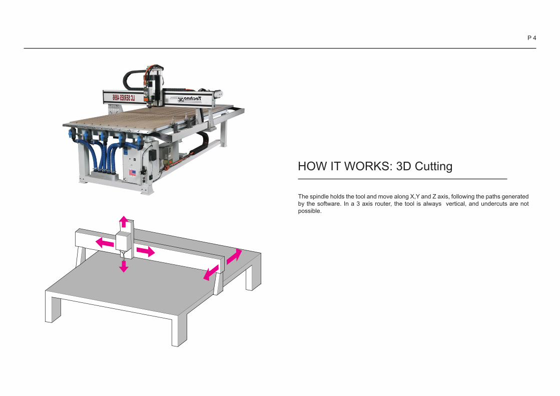
The spindle holds the tool and move along X,Y and Z axis, following the paths generated by the software. In a 3 axis router, the tool is always vertical, and undercuts are not possible.
HOW IT WORKS: 3D Cutting

P 5
The machine runs different cutting paths:
- Roughing cut, removing successive layers of material around the model
- Finishing cut, along the surface of the model
Note:
Other cutting paths can be eventually performed: - for refining concave edges that have been cut rounded with a rounded tool, - for adding an engraving on the surface of the model (a road on a site model, for example).
RoughingRoughing tool path
Finishing tool path Finishing
HOW IT WORKS: 3D Cutting
P 6
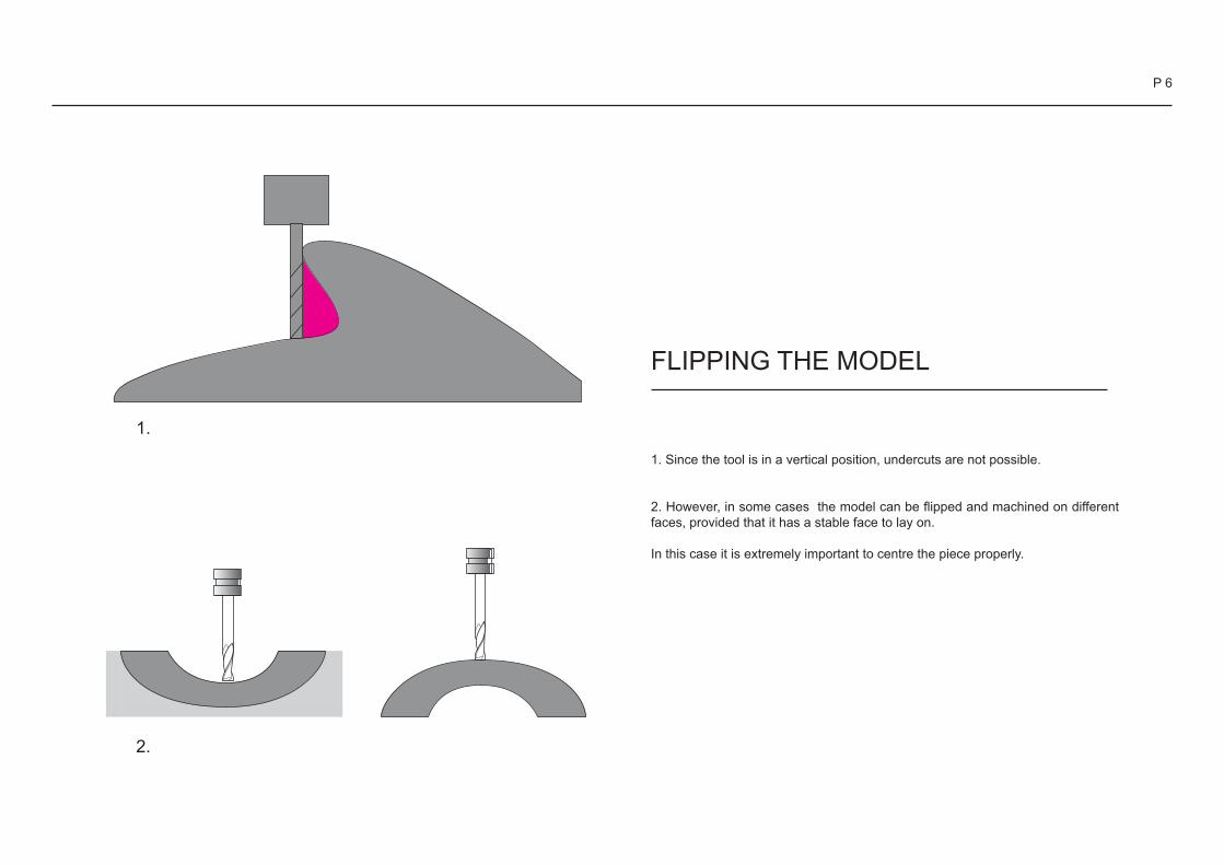
FLIPPING THE MODEL
1. Since the tool is in a vertical position, undercuts are not possible.
2. However, in some cases the model can be flipped and machined on different faces, provided that it has a stable face to lay on.
In this case it is extremely important to centre the piece properly.
1.
2.

P 7
LIMITS
1. the tools have a circular section, it means that the internal corners, seen by the top, are always rounded, only the radius can change.
2. Vertical walls can only be as high as the cutting part of the tool, not as the tool itself.
1.
2.
YES NO

P 8
YES NO
3.
4.
LIMITS
3. If the wall is steep, but not vertical, it can be as high as the tool
4. If the geometry of the model allows the space for the spindle, the cut can be deeper than the tool itself.

P 9
TOOLS
The tools used for cutting are many different kinds.
The most commonly used are:
1. endmill, with the flat edge, are mainly used for the roughing cut, and for refining flat horizontal surfaces and sharp corners;
2. ballnose, with a rounded edge, mainly used for finishing smooth surfaces;
3. veemill, used for engraving and for tapering edges;-drill bits, for making holes.
Some features to keep in mind:- a big tool can usually be longer then a small one;- a big tool can cut faster than a small one;- a big ball-nose tool can’t reach small valleys, but makes a smoother finish.
1. 2. 3.

P 10
SECTION 2
Available Machines

P 11
LARGE CNC MACHINE
Location: Digital Fabrication workshop
The larger CNC machine is operated by technicians in the digital fabrication workshop (Level 1 architecture building).

P 12
LARGE CNC MACHINE
What do we need?
• Save your model in Rhinoceros .3DM or .STL format• Make sure your model has no holes, the volume must be fully enclosed.• Model dimensions must be able to fit in the milling bed constraints (width, height and depth).

P 13
FILE SET UP 2D
File formats 2D Cutting:
Rhino 3D (.3dm), .dxf, .dwg, .ai, eps...
Max dimension:
1200 x 2400 x 50mm

P 14
FILE SET UP 3D
File formats 3D Cutting:
Rhino 3D (.3dm), .stl
Max dimension:
1200 x 2400 x 200mm
(in some cases the Z dimension can be up to 250, depending on the tools used).
P 15
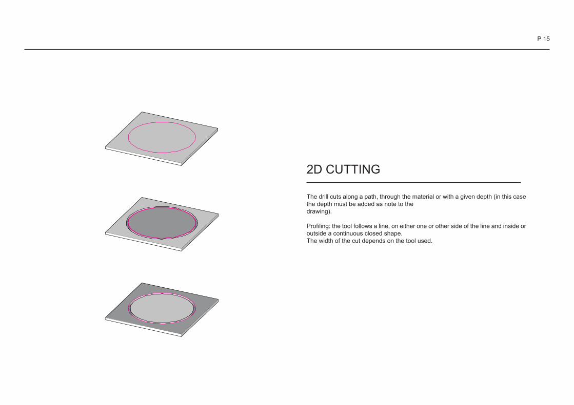
The drill cuts along a path, through the material or with a given depth (in this case the depth must be added as note to thedrawing).
Profiling: the tool follows a line, on either one or other side of the line and inside or outside a continuous closed shape.The width of the cut depends on the tool used.
2D CUTTING

P 16
Pocketing: the tool removes all material inside an outline, to a specified depth. Pocketing tool paths only work within closed shapes, all lines must be joined without any overlaps.
When cutting several pieces within one sheet of material, you must allow space for the tool, the thicker the material, the bigger the tool.
If there are many small pieces, they must be arranged on the board so that all of them are connected with a solid frame, in order to leave a small part uncut (keep them in position).
If the model is to be cut out entirely from the material, remember to add tabs around the model to keep it in place while milling.

P 17
MATERIALSIn some cases, it may be useful to have some spare material for making some test before cutting the model.
- MDF is very good for 2D cutting, being very flat.However the cut edges will have a fluffy surface finish not suitable for fine detail.
- Plywood is very good for 2D cutting.It can be used also for 3D cutting, giving an interesting stripped result.Solid wood is very good for 3D cutting.Wood with a fine grain, like totara, are better for fine details models
- Cibatool-chemical wood is perfect for small (high cost) and high detailed 3D cutting.
- Polystyrene is good for big dimension-low details model.The blue green one gives a better surface finish, but has a maximum height of 50mm, while the white one can be purchased in bigger dimension.
- Acrylic produces a reasonable finish but still requires a lot of wet sanding and polishing to get it clear again
- Aluminium can be 3D cut or engraved, but not cut through.
Other materials can be tested.
- Stone, concrete, glass and fibreglass can not be cut.

P 18
Location: OML officeSmaller CNC machines are located in the OML office, hand in your files at the OML office (Level 4, 421 architecture building)
SMALL CNC MACHINE

P 19
SMALL CNC MACHINE
What do we need?
• Save your model in Rhinoceros .3DM or .STL format• Make sure your model has no holes, the volume must be fully enclosed.• Model dimensions must be able to fit in the milling bed constraints (width, height and depth).

P 20
File formats 3D Cutting:
Rhino 3D (.3dm), .stl
Max dimension:
300 x 300 x 100mm
(in some cases the Z dimension varies depending on the tools used).
FILE SET UP 3D

P 21
SECTION 3
Preparing the File

P 22
To import a file go to:
File Import
Once you’ve selected the file you want to CNC, a pop-up window should appear with import options. Simply click OK
Note: You can also import .dxf and .dwg files
Importing the File to Rhino

P 23
Once imported the file will be placed according to the co-ordinates of its original file. In order to CNC the file properly we have to centre the object to the origin. To do this:
Type in “Move” into the command bar as highlighted left
Select the object/model
Select a vertex/point on the model (ideally from the base). This will be the point that touches the origin of the world plane within rhino
Type in “0” (zero) into the command bar and press “Enter”
Note: Make sure “Osnap” is enabled and either “End” (for polysurfaces) or “Vertex” (for meshes) is ticked to enable point selection
Positioning the Object for CNC

P 24
To check whether the object is closed properly type “ShowEdges” into the command bar. There should be no “naked edges” or “non-manifold edges” (which are usually highlighted pink if present).
For models with naked edges or non-manifold edges, type one or more of the following commands into the bar:
Join - Joins open polysurfaces, surfaces and meshes together
MeshBooleanUnion - Joins 2 closed meshes together to form one closed object
FillMeshHole(s) - Fills in holes of the mesh
MeshToNURB - When editing your object, it is best to convert your mesh to a NURB. This allows your object to be easier to modify especially when trimming/splitting is involved
Trim / Split - Removes excess parts of a polysurface or surface that prevents object from being closed. Needed for non-manifold edges
Preparing the Object for CNC

P 25
To engrave lines onto the object simply draw the curve using “Polyline” or “Control Point Curve” as highlighted left. Make sure the lines touch the object to ensure it engraves successfully. Type “Project” into the command bar and make sure you use a viewport that overlays the lines onto the right orientation.
Make sure the object fits in the CNC bed size. You can measure the object using the “Distance” command. Use “Scale” to modify the size if necessary.
Use layers to organise the objects. The object you want to CNC should ideally be in one layer. Engrave lines should be on another layer. You can do this by creating an new layer as shown bottom left. To change an objects layer:
Select the object you want to change
Right-click the layer you wish to move the object to
Select “Change Object Layer”
Preparing the File Continued

P 26
There are two choices for saving your file:
3D cutting requires either a Rhino file or an .STL file
2D cutting requires a .dwg, .dxf, .ai or rhino file
To save the file go to:
File
Export Selected
Select the object
Hit “Enter” Click on the drop down menu on the pop-up window and select the file type suitable for your model. Make sure you choose “Rhino 5 3D Models” option when choosing rhino
Save
Note: Doing this cleans up the file and makes sure only the model you want to CNC is there without the working lines/surfaces
Saving the file