GUI Fugui 2005/04/26. 2 Outline I. GUI overview II. GUI description III. Use GUI IV. GUI principle.
1
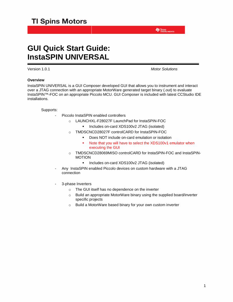
GUI Quick Start Guide: InstaSPIN UNIVERSAL
Version 1.0.1 Motor Solutions Overview InstaSPIN UNIVERSAL is a GUI Composer developed GUI that allows you to instrument and interact over a JTAG connection with an appropriate MotorWare generated target binary (.out) to evaluate InstaSPIN™-FOC on an appropriate Piccolo MCU. GUI Composer is included with latest CCStudio IDE installations. Supports:
- Piccolo InstaSPIN enabled controllers o LAUNCHXL-F28027F LaunchPad for InstaSPIN-FOC
Includes on-card XDS100v2 JTAG (isolated) o TMDSCNCD28027F controlCARD for InstaSPIN-FOC
Does NOT include on-card emulation or isolation Note that you will have to select the XDS100v1 emulator when
executing the GUI o TMDSCNCD28069MISO controlCARD for InstaSPIN-FOC and InstaSPIN-
MOTION Includes on-card XDS100v2 JTAG (isolated)
- Any InstaSPIN enabled Piccolo devices on custom hardware with a JTAG connection
- 3-phase Inverters
o The GUI itself has no dependence on the inverter o Build an appropriate MotorWare binary using the supplied board/inverter
specific projects o Build a MotorWare based binary for your own custom inverter

2
Version: 1.0.1
Revision History:
1.0.1 October 30, 2013 First release

3
Table of Contents
Installation .................................................................................................................................................. 4
Hardware Set-up ......................................................................................................................................... 5
Overview of Process for using the GUI ...................................................................................................... 5 Create Binary ...................................................................................................................................................................................6 GUI Connection ...............................................................................................................................................................................7 Running the GUI ..............................................................................................................................................................................8
Standalone GUI .exe ........................................................................................................................... 8
GUI inside CCStudio IDE ................................................................................................................... 9
Use Example ............................................................................................................................................. 12 Hardware Set-up ........................................................................................................................................................................... 13 Software Projects .......................................................................................................................................................................... 14 Updating software for your motor (user.h) ................................................................................................................................... 16 Using the GUI ............................................................................................................................................................................... 21
Start-up Options ................................................................................................................................ 21
Motor ID ........................................................................................................................................... 22
Motor ID Tips ................................................................................................................................... 23
Motor ID Sanity Checks ................................................................................................................... 25
Update user.h settings ....................................................................................................................... 26
Controller Tuning ............................................................................................................................. 27
Next Steps ................................................................................................................................................. 29

4
Installation 1. Run the UNIVERSAL GUI installation .exe using the latest version from
http://www.ti.com/tool/instaspinfocmotorwaregui a. Accept the license agreement
b. Recommended to keep default destination location
2. Install Code Composer Studio v5.5+ from
http://processors.wiki.ti.com/index.php/Download_CCS

5
Hardware Set-up 1. Please review the quick start and/or hardware guides for your particular controlCARD /
LaunchPad and motor drive kit – available through MotorWare - for details of hardware set-up, including jumper and switch settings
Overview of Process for using the GUI 1. Create Binary from MotorWare Project using CCStudio
2. Launch GUI Composer UNIVERSAL GUI using either method:
a. Standalone
b. Inside of CCStudio

6
Create Binary 1. This GUI only allows you to instrument bound variables that exist in the compiled .out
that will be loaded onto the Piccolo MCU
a. Variables that you interact with are primarily in the gMotorVars structure
b. A variable existing in gMotorVars does NOT mean that the variable is being used in the source project
i. Ex: the ability to change the Speed Kp is not made available until proj_lab05b
1. CTRL_setKp(ctrlHandle,CTRL_Type_PID_spd,gMotorVars.Kp_spd);
ii. If you compile and load proj_lab03.c do not be surprised when changing Speed Kp has no effect!!
c. Insure variables you want to instrument are actually interfaced to in the .c that is compiled. Doing a text search in the .c for the gMotorVars.xxxx will tell you if it is being updated in that project.
2. You must use CCStudio to compile an appropriate MotorWare project into a .out
a. CCS version and compiler version notes
i. CCS (download)
1. For using the GUI inside of CCS GUI Composer you must use CCSv5.5+
2. If not using the GUI inside of CCS you may use CCSv5.4
ii. Compiler (download or through Help Check for Updates)
1. Recommend 6.2.3+, or if necessary version 6.1.5
2. Do NOT use compiler versions 6.2.2 or 6.2.1, they include an IQMath compiler bug
3. You should select the MotorWare project that meets your application needs
4. This project should be built with the appropriate user.h settings selected
a. It is recommended to follow the InstaSPIN Projects & Labs User's Guide in MotorWare
b. See the “Use Example” section of this document for a quick overview and example

7
GUI Connection 1. With the DC bus powered, connect USB from your PC to J1 on controlCARD
2. If using the high voltage kit, proceed with connecting to the target before energizing the high voltage AC input (110-220Vac) or high voltage DC Bus (50-350Vdc)
3. You can verify that you connected to the FTDI XDS100v2 emulator by checking your Windows Device Manager for Ports: USB Serial Port (COMxxx) and TI XDS100 Channel A and B

8
Running the GUI Standalone GUI .exe
1. Two “webapps” are provided during installation at C:\ti\guicomposer\webapps
a. The only difference between the content of these two folders is the “.appsetting” file, which assigns the default MCU, Emulator, and points to the .out to be programmed.
i. Default XDS100v2 emulator, F28069 or F28027 MCU, appProgram.out
b. All other content in the folders is 100% identical
2. The compiled .out that you have built must be renamed appProgram.out and copied to the appropriate webapp folder
a. Note: If you plan to use the standalone GUI often with a new compile from a single project you can update the default naming of “appProgram.out” to anything you like (ex: “proj_lab05b.out” or “my_project.out”) to save yourself having to rename the file each time.
i. Use a text editor to update the .appsettings file
3. Run the executable from the webapp folder: InstaSPIN_UNIVERSAL.exe
4. The GUI Composer application will start
5. GUI Composer will initialize, then:
a. attempt to connect through the XDS100v2 emulator
b. to the Piccolo device
c. load \appProgram.out into the memory of the Piccolo device.
i. a, b, c are all specified in .appsettings and may be permanently changed if required by using a text editor

9
d. If you are using a different emulator the connection will fail
i. you can permanently change the default emulator in the .appsettings file or select the appropriate one from the drop-down menu and then click Initialize
6. This launching process should take less than 1-3 minutes
a. In rare cases we have seen it take an usually long amount of time. This is likely due to software running on your PC that is redirecting HTTP or browser sockets. Try to disable any software of this type.
Configuration Tab of a successful GUI Launch
GUI inside CCStudio IDE
1. Zip one of the “webapps” folders, ex:
a. C:\ti\guicomposer\webapps\InstaSPIN_F2802xF_UNIVERSAL
2. In CCSv5.5+, VIEW GUI Composer
3. Select Import Project Icon, and point to the Zip you created
a.
4. This will create a webapp folder in your CCS workspace
a. You select this location each time you start CCStudio

10
b. ex: C:\workspace\.GUIComposerWS\InstaSPIN_F2802xF_UNIVERSAL
5. The GUI can be selected by double clicking on the Projects app.html file:
6. The GUI opens in edit mode. To view in preview mode (interact like it is a standalone GUI) select the Play arrow:
7. To use the GUI in CCS you still need to follow the steps that are done automatically by the standalone .exe
a. Import an emulation+cpu “Target Configuration”
i. View Target Configurations
ii. Right Click
iii. \sw\ide\ccs\ccs5\targetConfigs\TMS320F28027_xds100v2.ccxml
b. Launch deubg session
i. Right Click on the .ccxml file
c. Connect target
i.
d. Load compiled .out Program (or symbols if program is already in MCU flash)
i.
ii.

11
iii.
iv.
e. Enable silicon realtime mode
i.
ii. To enable realtime mode select
f. Run Resume
i.
g. See the MotorWare InstaSPIN Projects and Labs User’s Guide for more details:
8. You can now use the GUI to instrument the code running on the MCU
9. For details on how to customize this GUI, create your own, or export for standalone use please see the GUI Composer Wiki Site.

12
Use Example Controller: LAUNCHXL-F28027F
Inverter: BOOSTXL-DRV8301
Motor: Anaheim Automation BLY172S-24V-4000: 24V, 8 poles, 4K RPM
13
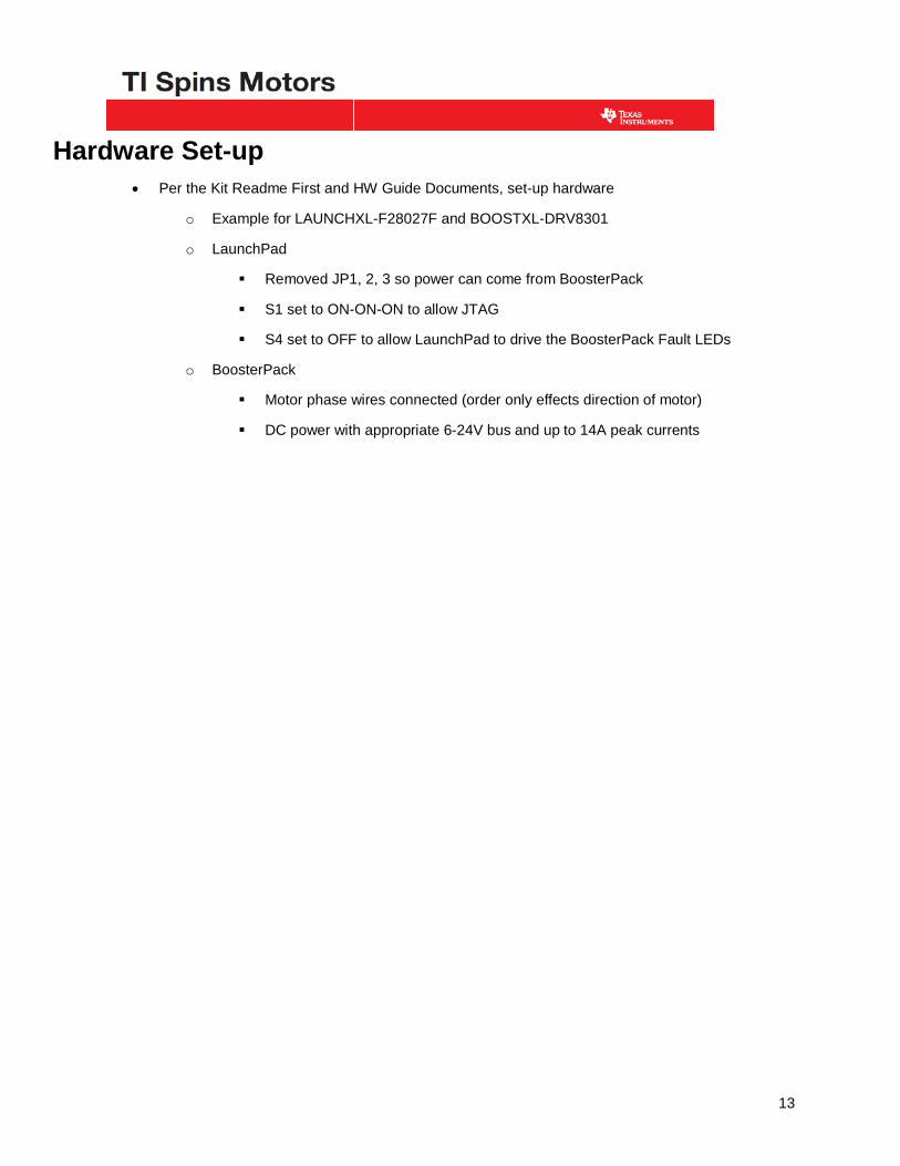
Hardware Set-up • Per the Kit Readme First and HW Guide Documents, set-up hardware
o Example for LAUNCHXL-F28027F and BOOSTXL-DRV8301
o LaunchPad
Removed JP1, 2, 3 so power can come from BoosterPack
S1 set to ON-ON-ON to allow JTAG
S4 set to OFF to allow LaunchPad to drive the BoosterPack Fault LEDs
o BoosterPack
Motor phase wires connected (order only effects direction of motor)
DC power with appropriate 6-24V bus and up to 14A peak currents

14
Software Projects • In CCS, Projects Import and point to the latest version of the MotorWare “CCS5” directory
for your combination of solution, board, and MCU Ex: InstaSPIN_FOC, the BoosterPack, F2802xF C:\ti\motorware\motorware_01_01_00_10\sw\solutions\instaspin_foc\boards\boostxldrv8301_revB\f28x\f2802xF\projects\ccs5
o You may select any or all of the projects
Make sure you do NOT select to “Copy projects into workspace” or the project will not find appropriate file references during build. We recommend working directly out of the C:\ti\motorware\ directory.
The main projects you will likely want to use, in order
• Lab5b – interface to tune the current and speed controllers
• Lab9 – field weakening
• Lab10a – over-modulation
• Lab5a – Torque control with PI tuning, no speed controller

15

16
Updating software for your motor (user.h) • Open the associated src\user.h file in CCS Project Explorer or using a text editor
C:\ti\motorware\motorware_01_01_00_10\sw\solutions\instaspin_foc \boards\boostxldrv8301_revB\f28x\f2802xF\src\user.h
• User.h can look overwhelming, but do not fear!
o Most #define variables should not be modified and many are pre-compile calculations
In future MotorWare versions this will be updated so only the most relevant are made visible and the rest will be accessible if required
• Update these key user.h variables in each section
o //! \brief CURRENTS AND VOLTAGES
#define USER_IQ_FULL_SCALE_FREQ_Hz (600.0)
• Set to the highest speed you want to run, where Hz = RPM * poles / 120
• My example
o 4 kRPM 8 pole motor = 267 Hz, but unloaded it will run faster and I expect to use field weakening to double my speed
o Use (600) Hz as my maximum
#define USER_IQ_FULL_SCALE_VOLTAGE_V (42.0)
• We will use the GUI Variable Overflow Checks to set this value once we identify the flux
• For very low flux motors often used with the BoosterPack+LaunchPad to maximize variable resolution we may be updating to as low as half of #define USER_ADC_FULL_SCALE_VOLTAGE_V (26.314)
• This variable effects the SMALLEST flux value that can be identified
o Ex: 0.002 V/Hz is a very small flux typically seen in high speed 12V hobby motors
o Smallest flux = IQ_FULL_SCALE / Effective Estimation Frequency / 0.7
Effective Estimation Frequency is set in the DECIMATION section below and = PWM_FREQ / PWM_TICKS_PER_ISR / ISR_TICKS_PER_CTRL / EST_TICKS_PER_CTRL
Ex for 45V and 10 kHz effective estimation, smallest flux value = 0.0064 V/Hz
To give some headroom we could solve for 0.0015 V/Hz * 0.7 / 15 kHz estimation = 15.75 V

17
For Motor ID an IQ_FULL_SCALE value of (15) with estimation frequency of 15 KHz should work
• My example o Using default of (42.0), may update after ID
o //! \brief CLOCKS & TIMERS
#define USER_PWM_FREQ_kHz (30.0)
• Very low inductance, high short circuit currrent motors will require 45-60 kHz typical; most other motors you will PWM in the 8-30 KHz range, using lower PWMs when possible to reduce switchign losses.
• My example
o Using default of (30) KHz
o //! \brief DECIMATION
Determines rates of the control loops and effects interrupt loading
ISR = PWM_FREQ / USER_NUM_PWM_TICKS_PER_ISR_TICK
• Uses ePWM 1st/2nd/3rd event hardware to trigger the ADC start of conversion; the ADC conversion done interrupt acts as the main ISR for the control system
• Best if ISR is <= 15 KHz maximum, and <= 10 KHz typical
o If not possible be sure to test using FEM and CPU_USAGE functions using lab3b
CTRL = ISR / ISR_TICKS_PER_CTRL
• Insure CTRL is effective <=15 kHz
o Be careful of 15 KHz rates on 60 MHz MCUs, you may over flow the interrupt as more system code is added, especially during the motor identification process
o If unsure, test using FEM and CPU_USAGE functions using lab3b
• CURRENT = CTRL / CTRL_TICKS_PER_CURRENT
o 5-15 KHz typical
• EST = CTRL / CTRL_TICKS_PER_EST
o Whole divisor of CURRENT, 2.5-15 KHz typical
• SPEED = CTRL / CTRL_TICKS_PER_SPEED
o 1 KHz typical
• TRAJ = CTRL / CTRL_TICKS_PER_TRAJ

18
o Same as speed, 1 KHz typical
My example
• ISR (3) to get effective 30 kHz / 3 = 10 kHz ISR
• CTRL (1) for 10 kHz
• EST (1) and CURRENT (1) for 10 kHz
• TRAJ (10) and SPEED (10) for 1 kHz
o //! \brief LIMITS
#define USER_ZEROSPEEDLIMIT (0.002)
• ZEROPSPEEDLIMIT * USER_IQ_FULL_SCALE_FREQ_Hz If the ForceAngle flag is set during opertation, this will be the +/- Hz region where the angle feedback used in the control is generated from a ForceAngle instead of FAST estimation
• My example
o USER_ZEROSPEEDLIMIT (0.005)
o ForceAngle = 0.005 * 600 = 3 Hz = +/- 45 RPM
o //! \brief USER MOTOR & ID SETTINGS
Each motor saved must have a unique enumeration
• #define Anaheim_BLY172S 102
• #define My_Motor 103
Comment out (//) all but one USER_MOTOR selection
19
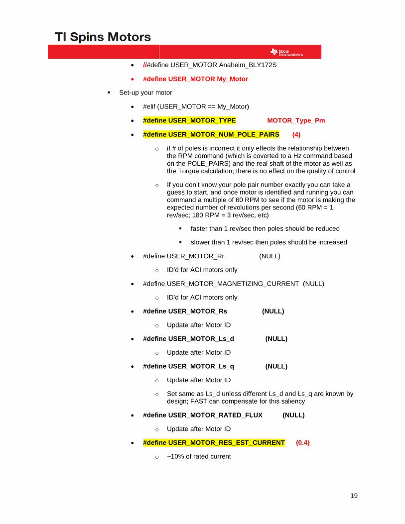
• //#define USER_MOTOR Anaheim_BLY172S
• #define USER_MOTOR My_Motor
Set-up your motor
• #elif (USER_MOTOR == My_Motor)
• #define USER_MOTOR_TYPE MOTOR_Type_Pm
• #define USER_MOTOR_NUM_POLE_PAIRS (4)
o if # of poles is incorrect it only effects the relationship between the RPM command (which is coverted to a Hz command based on the POLE_PAIRS) and the real shaft of the motor as well as the Torque calculation; there is no effect on the quality of control
o If you don’t know your pole pair number exactly you can take a guess to start, and once motor is identified and running you can command a multiple of 60 RPM to see if the motor is making the expected number of revolutions per second (60 RPM = 1 rev/sec; 180 RPM = 3 rev/sec, etc)
faster than 1 rev/sec then poles should be reduced
slower than 1 rev/sec then poles should be increased
• #define USER_MOTOR_Rr (NULL)
o ID’d for ACI motors only
• #define USER_MOTOR_MAGNETIZING_CURRENT (NULL)
o ID’d for ACI motors only
• #define USER_MOTOR_Rs (NULL)
o Update after Motor ID
• #define USER_MOTOR_Ls_d (NULL)
o Update after Motor ID
• #define USER_MOTOR_Ls_q (NULL)
o Update after Motor ID
o Set same as Ls_d unless different Ls_d and Ls_q are known by design; FAST can compensate for this saliency
• #define USER_MOTOR_RATED_FLUX (NULL)
o Update after Motor ID
• #define USER_MOTOR_RES_EST_CURRENT (0.4)
o ~10% of rated current

20
o Used to ineject current for Rs test AND to start-up motor for Ramp_Up. For high cogging torque motors increase RES_EST_CURRENT until the motor spins
• #define USER_MOTOR_IND_EST_CURRENT (-0.4)
o NEGATIVE ~10% of rated current
o Used to weaken the field during Ls testing
• #define USER_MOTOR_MAX_CURRENT (4.0)
o Rated current of motor
o This is maximum Iq torque command produced by the Speed PI controller, IF using the speed PI controller
• #define USER_MOTOR_FLUX_EST_FREQ_Hz (30.0)
o ~10% of rated max speed = 267 Hz * 10%
o Important to that this is high enough as we measure the voltage produced by flux (V/Hz) which will be larger at higher Hz, especialy for low flux (high speed) motors
o Also note resolution comments in the USER_IQ_FULL_SCALE_VOLTAGE_V section
• After saving the user.h file, Right Click on and build the appropriate project

21
Using the GUI • For Standalone Mode, follow the instructions in the section above:
Running the GUI Standalone GUI .exe
o Copy the .out just built to the appropriate Webapp folder, and rename to “appProgram.out” ex:
…\sw\solutions\instaspin_foc\boards\boostxldrv8301_revB\f28x\f2802xF\projects\ccs5\proj_lab05b\Flash\proj_lab05b.out
to the appropriate webapp folder:
C:\ti\guicomposer\webapps\InstaSPIN_F2802xF_UNIVERSAL\appProgram.out
o Run the executable C:\ti\guicomposer\webapps\InstaSPIN_F2802xF_UNIVERSAL\InstaSPIN_UNIVERSAL.exe
Start-up Options
RsRecalc
If ENABLED - when Run is enabled - Performs a recalculation of Rs.
If DISABLED – when Run is first enabled – uses the most recent value of Rs.
Rs accuracy is critical for low speed operation. Rs changes as the motor windings heat from high current usage = high torque demanded from the motor. Loaded washing agitation is a good example. See the Rs On-line (always running recalibration) feature in MotorWare Lab7 if required.
OffsetCalc
If ENABLED – when Run is enabled - performs a recalculation of the ADC offsets.
Length of this recalibration is adjustable, see the User’s Guide.
Values can be saved and loaded from user.h, bypassing this calculation in the future.
Important Notes:
• If the USER_IQ_FULL_SCALE_VOLTAGE or CURRENT values are changed the saved offsets must be changed as well.
• If DISABLED the offset values / adcBias will be loaded from user.h settings only. Only ever DISABLE if the final values are in user.h!!!

22
ForceAngle
Force Angle can be thought of as trajectory generation for the angle feedback (replacing FAST over a user set area) to the FOC controller. It creates an estimated angle that rotates at a user set rate (in user.h).
It should be used whenever FAST is not producing an accurate angle estimate, i.e. at initial start-up and if trying to operate continuously at very low speeds.
It should be ENABLED when first starting and then DISABLED for normal operation, unless you plan to run continuously at very low speed or have a very slow transition through zero speed.
While application/motor/sense/acceleration dependent, once the motor is running you will often continue to track through zero speed well enough (depending on Bemf and deceleration rate).
Motor ID
To perform a Motor Identification:
• SELECT Enable System
• user.h Params is NOT selected
• Start-up Options
o Recommend keeping OffsetCalc, RsRecal and ForceAngle selected
• SELECT Run
user.h Params
If user.h Params is enabled when Run is selected, the control system will bypass Motor ID and
• Load all settings from user.h, including Offsets and all USER_MOTOR settings
• Do not select until you have updated the user.h fully
Motor Identification States
This is fully covered in the User’s Guide Chapter 6. Following is the example for the PM Synchronous Motor.
• OffsetRecalc is performed before the Motor ID process begins

23
• EST_State_
o RoverL
Injects ½ of USER_MOTOR_RES_EST_CURRENT at USER_R_OVER_L_EST_FREQ_Hz
o Rs
Injects USER_MOTOR_RES_EST_CURRENT
o RampUp
Starts motor using current amplitude of USER_MOTOR_RES_EST_CURRENT at a rate of USER_MAX_ACCEL_EST_Hzps until speed of USER_MOTOR_FLUX_EST_FREQ_Hz
Motor must continue spinning until Idle or ID results should be considered invalid
o RatedFlux
Current is minimized while keeping speed to detect Flux
o Ls
Injects USER_MOTOR_IND_EST_CURRENT into Id (field weakening) to detect the inductance
o RampDown
ID process ends and motor slows to 0 speed
o Idle
• While you should insure that the Motor Identified light turns green, this does NOT mean that the identified parameters are correct, just that the identification state finished without a serious error
o You can start ID without a motor even attached and still get a green light. This only alerts you to very specific and serious errors
Motor ID Tips
• Scaling of hardware Vph and USER_IQ_FULL_SCALE_VOLTAGE is critical, especially for low inductance (high speed motors)
• Note that during Motor ID there are wait time time-outs established for each step. These times may need to be increased for the RampUp especially if you increase the ID speed or decrease the Estimation Frequency
o See “user.c”
• RoverL

24
o If RoverL is >= 2000 there is a variable overflow, so you MUST use lab2c to attempt ID (this happens with low Ls / high speed motors)
o Can also increase USER_R_OVER_L_EST_FREQ_Hz to (300) for low Ls motors
• Rs
o Be very sure to use 10% of I-rated for USER_MOTOR_RES_EST_CURRENT
o important not to overheat the motor with too high a current
• Ramp_Up
o High Cogging Torque motors may not start-up
Increase USER_MOTOR_RES_EST_CURRENT
o When USER_MOTOR_FLUX_EST_FREQ_Hz is increased (see Ls) the Ramp_Up may time out
Increase USER_MAX_ACCEL_EST_Hzps to hit the target speed before time-out
• Rated_Flux
o If the motor stops spinning increase USER_MOTOR_FLUX_EST_FREQ_Hz
o The smallest flux that can be ID’d = USER_IQ_FULL_SCALE_VOLTAGE_V / FAST_EST_Hz / 0.7
For small flux machines (small motors, high speed) lower USER_IQ_FULL_SCALE_VOLTAGE_V to increase the resolution
• Ls
o If the motor stops spinning or the Ls values are not stable and consistent increase USER_MOTOR_FLUX_EST_FREQ_Hz
o Increase PWM frequency to 30, 45, 60, and use lab2c
Values Returned for this example

25
Motor ID Sanity Checks
• Rs / Ls
o R/L gives a theoretical limitation of speed with a stable voltage source
Note: the GUI displays Ls in mH, not H
o Is this larger than your MAX_Hz? Does it seem reasonable for your motor?
~2.5x my rated max frequency is reasonable
o Note that High speed motors are often mis-designed with very low Ls, resulting in Rs / Ls much larger than MAX_Hz
• Flux / 2pi / Ls = Short Circuit Current = Isc
o Typically 2x+ the rated current and often much larger for small Ls machines
o Large Isc = low Ls = high speed, high current
o Larger Isc will require faster PWM (30-60 KHz) and possibly faster current control (15 KHz)
• Overflow / Resolution Checks, adjustment of IQ_VOLTAGE
o Minimize Full Scale Voltage vs. Full Scale Frequency to maximize resolution
For Low flux motors this often means reducing the IQ_FULL_SCALE_VOLTAGE
• For my example, I will update user.h to (24.0)
For High flux motors this often means increasing the IQ_FULL_SCALE_VOLTAGE to support the Bemf voltage at highest speeds
• For example a 1.2 V/Hz motor will produce 1200V at 1KHz!
o FAST Frequency vs. Full Scale Voltage
Alerts that low flux motors should use a smaller IQ_FULL_SCALE_VOLTAGE to increase resolution or run the FAST EST_FREQ at a higher rate

26
Update user.h settings
adcBias (Offsets) for Example Hardware
• Copy and paste the adcBias 0/1/2 values to the I_A/B/C_offset and V_A/B/C_offset #defines
o Note, since I chose to change my IQ_VOLTAGE from (42.0) to (24.0) in previous section these offsets are no longer valid as they change with your IQ scaling.
o After recompiling and running again, update the adcBias in user.h
• Copy and paste the identified motor parameters to the USER_MOTOR #defines
o Note: The GUI displays inductance in mH while the user.h is in H.
o Be sure to paste the GUI Ls_d / Ls_q value with a leading 0.000
• Recompile and use the .out with your GUI if you want to be able to skip Motor ID in the future (enable the user.h Params before you select Run)

27
Controller Tuning
Default Controller Tuning
Speed Current & Torque
Note that both current and speed controller gains are effected by the IQ scaling variables and decimation timing, they will need to be changed as well if you update these user.h settings.
Current Controllers
• The Iq and Id Current PI controller gains are numerically calculated & initialized
o Kp = ¼ * Bandwidth
Bandwidth = [ Ls / CTRL_FREQ_Hz * IQ_CURRENT / IQ_VOLTAGE ]
This ¼ factor is just to loosen the controller to support initial motor bring-up
For high speed and high dynamics you must increase Kp by up to a factor of 4
o Ki = CTRL_FREQ_Hz / Ls * Rs
• These can be changed simply through the GUI, which instruments the following user code
o gMotorVars.Kp_Idq = CTRL_getKp(ctrlHandle,CTRL_Type_PID_Id);
o CTRL_setKp(handle,CTRL_Type_PID_Id,gMotorVars.Kp_Idq);
• Some applications may want to do step response testing to meet desired response of over/undershoot and settling time
• Note, current controllers can only be updated starting in proj_lab5a, previous to this any changes to those variables in the GUI will have no effect
Speed Controller
• The PI Speed Control cannot be auto tuned based on the motor or system parameters

28
o Speed control relies on knowledge of inertia, mechanical linkages, and desired response
o Speed Gains are initialized using a “rule of thumb”, which works decently for larger flux motors
Kp = 0.02 * MAX_HZ * MAX_CURRENT / IQ_CURRENT
Ki = 2.0 * CTRL_HZ * MAX_HZ * MAX_CURRENT / IQ_CURRENT
Experience shows that for low inertia motors a good starting point is to reduce the default Kp and Ki by /4
• Tuning
o Tune by testing various speeds and loads or tune by step response inputs (most popular)
o May need to “gain stage”, different KpKi sets for different speeds/loads/accelerations
o May be able to empirically calculate if you know inertia (see Labs/UG)
o Zero Speed tuning & experiment
Disable ForceAngle
Set 0 speed
Quickly rotate the motor shaft 90-180 deg and then let go
• Now set Speed Kp to 0.2, Ki to 0.004
o example for Anaheim motor under test
o Notice how the motor shaft behaves like a spring-damper system, “compressing” as you turn and then “returning” once you remove the load
• Increase Kp until the spring feeling is gone
• Increase Ki to increase the stiffness of the motor
• At this point the system might be slightly unstable, the following can help stabilize the system:
o Increase Kp to increase the dampening
o Reduce Ki to reduce oscillations
• These can be changed simply through the GUI, which instruments the following user code
o gMotorVars.Kp_spd = CTRL_getKp(ctrlHandle,CTRL_Type_PID_spd);
o CTRL_setKp(handle,CTRL_Type_PID_spd,gMotorVars.Kp_spd);
• Note, speed controllers can only be updated starting in proj_lab5b, previous to this any changes to those variables in the GUI will have no effect

29
Next Steps • Continue to follow the InstaSPIN Projects & Labs User's Guide in MotorWare
• Read through the User’s Guide on relevant topics for your application
• Ask questions on the InstaSPIN e2e forum
WARNING
Do not close the GUI until the drive has been stopped. Failure to do so will leave the program running or put the processor into an unknown state, causing the system to continue to draw current, possibly damaging the controlCARD, board, host computer, motor and posing a fire hazard. After proper shut-down always disconnect the power supplies and remember that capacitors are charged and will take time to dissipate!