
GTI Installation Guide for SW Series
54
Installation Guide Grid Tie Interface (GTI) SW Series SW4024, SW4048, SW5548
Transcript of GTI Installation Guide for SW Series

Installation Guide
Grid Tie Interface (GTI)SW SeriesSW4024, SW4048, SW5548

ii© 2002 Xantrex Technology Inc.
P/N 975-0041-01-02 Rev A 03/02
About XantrexXantrex Technology Inc., is a world-leading supplier of advanced power
electronics and controls with products from 50 watt mobile units to 1 MW utility-scale systems for wind, solar, batteries, fuel cells, microturbines, and backup powerapplications in both grid-connected and stand-alone systems. Xantrex productsinclude inverters, battery chargers, programmable power supplies, and variablespeed drives that convert, supply, control, clean, and distribute electrical power.
TrademarksTrace and Xantrex are registered trademarks of Xantrex International.
Notice of CopyrightGrid Tie Interface (GTI) Installation Guide ©March 2002 Xantrex Technology
Inc. All rights reserved.
DisclaimerWhile every precaution has been taken to ensure the accuracy of the contents
of this guide, Xantrex International assumes no responsibility for errors oromissions. Note as well that specifications and product functionality may changewithout notice.
Since the use of this manual and the conditions or methods of installation,operation, use and maintenance of the unit are beyond the control of XantrexTechnology Inc., the company does not assume responsibility and expresslydisclaims liability for loss, damage, or expense arising out of or any way connectedwith such installation, operation, use, or maintenance.
Due to continual improvement through product updates, photographs and/orillustrations used in this manual may not exactly match your unit. XantrexTechnology Inc., reserves the right to update this product without notice or releasingan updated manual when fit, form or function are not affected.
Date and RevisionMarch 2002, Revision A
Part Number975-0041-01-02
Contact InformationWeb: www.xantrex.com
Email: [email protected]
Phone: 360/435.8826
Fax: 360/435.2229

© 2002 Xantrex Technology Inc.P/N 975-0041-01-02 Rev A 03/02 iii
IMPORTANT SAFETY INSTRUCTIONSThis manual contains important safety instructions that should be followed
during the installation and maintenance of this product.
To reduce the risk of electrical shock, and to ensure the safe installation andoperation of this product, the following safety symbols have been placedthroughout this manual to indicate dangerous conditions and important safetyinstructions.
��������- A DANGEROUS VOLTAGE ORCONDITION EXISTS IN THIS AREA. USE EXTREMECAUTION WHEN PERFORMING THESE TASKS.
����������- UNE TENSION OU CONDITIONDANGEREUSE EXISTE DANS CETTE ZONE. FAIREPREUVE D’EXTRÊME PRUDENCE LORS DE LARÉALISATION DE CES TÂCHES.
�� ����- This procedure is critical to the safeinstallation or operation of the unit. Follow theseinstructions closely.
�������- Cette procédure est essentielle àl’installation ou l’utilisation de l’unité en toutesécurité. Suivre ces instructions de près.
�����- This statement is important. Follow instructionsclosely.
�����- Cette déclaration est importante. Suivre lesinstructions de près.
• All electrical work must be done in accordance with local, national, and/orinternational electrical codes.
• Before installing or using this device, read all instructions and cautionarymarkings located in the manual, and on the inverter, the batteries, and the PVarray.
• Do not expose this unit to rain, snow, or liquids of any type. This product isdesigned only for indoor mounting.
• To reduce the chance of short-circuits use instulated tools when installing orworking with the inverter, the batteries, or the PV array.
• Remove all jewelry while installing this system. This will greatly reduce thechance of accidental exposure to live circuits.

iv© 2002 Xantrex Technology Inc.
P/N 975-0041-01-02 Rev A 03/02
������������������ �
• The unit contains more than one live circuit (inverter and utility grid). Powermay be present at more than one source.
• This product contains no user-serviceable parts. Do not attempt to repair thisunit.
• To reduce risk of electric shock, disconnect all wiring before attempting anymaintenance or cleaning.
• Do not mount this device in unventilated enclosures.
• To reduce risk of electric shock, disconnect all wiring before attempting anymaintenance or cleaning.
• Additional AC disconnects may be required as part of the system installation.Consult local and national electrical code requirements.
• This unit is designed to be horizontally wall mounted.
• The AC input and output neutral conductors are not connected (bonded) tothe chassis.
• The AC input and output HOT conductor are not isolated from each other.
• The chassis housing of the GTI must be connected to a permanent groundingsystem as required by the National Electric Code, ANSI/NFPA 70-1996. This isthe responsibility of the system installer. A grounding terminal lug is providedfor connection of an equipment grounding conductor.
• CSA certified for sale in the U.S. under Photovoltaic Power Systems (UL1741).
IMPORTANT SAFETY INSTRUCTIONS (Continued)

© 2002 Xantrex Technology Inc.P/N 975-0041-01-02 Rev A 03/02 v
��������
IMPORTANT SAFETY INSTRUCTIONS ............................................................. iii
��������������� �������������������������������������������������������������� �
Introduction .......................................................................................................... 1Standard Features ................................................................................................. 4
Utility Interactive Mode .................................................................................... 4Bypass Mode .................................................................................................... 4
������� ��������� ����������������������������������������������������������������� �
Pre-Installation ...................................................................................................... 5Required Tools and Materials .......................................................................... 5Removing the Top Cover .................................................................................. 5
Mounting ............................................................................................................... 6Procedure .......................................................................................................... 6
Wiring .................................................................................................................... 8AC Wiring for Single-Inverter Installations ...................................................... 8
Ground Wiring ........................................................................................... 10Utility Grid AC Wiring to the GTI .............................................................. 12Inverter AC Input Wiring to the GTI .......................................................... 14Inverter AC Output Wiring to the GTI ....................................................... 16GTI Wiring to the Sub-Panel ...................................................................... 18Communications Cable ............................................................................. 20
AC Wiring for Dual-Inverter Installations ...................................................... 22Ground Wiring ........................................................................................... 24Utility Grid AC Wiring to Dual GTIs .......................................................... 26Inverter AC Input and Output Wiring to the GTIs ................................... 28GTI Wiring to the Sub-Panel ...................................................................... 30Connecting the Communications Cables for Dual Inverter Installations 30
AC Rewiring for Dual-Inverter Power Panel Installations ............................. 32AC Rewiring for Power Module Installations ................................................ 34AC Rewiring for Power Module Installations (continued) ............................ 36
Wiring Check ....................................................................................................... 37Operating Stacked Inverters ............................................................................... 37Start-up and Test ................................................................................................. 37
����������� ������� ����������������������������������������������������� ��
������������ ������������ ��������������������������������������������
Electrical Specifications1 .................................................................................. A-1Mechanical Specifications ................................................................................ A-1
��������������������� � ��������������� ���� ���
Warranty ............................................................................................................ B-1Return Material Authorization Policy ............................................................... B-2
Return Material Procedure ........................................................................... B-2Service Information .......................................................................................... B-3

vi© 2002 Xantrex Technology Inc.
P/N 975-0041-01-02 Rev A 03/02
�������������
Figure 1-1 Grid Tie Interface Flow Diangram .......................................................... 2
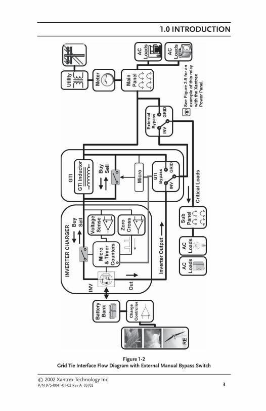
Figure 1-2 Grid Tie Interface Flow Diagramwith External Manual Bypass Switch ................................................. 3
Figure 1-3 Grid Tie Interface Unit ............................................................................. 4
Figure 2-1 Removing the Top Cover ......................................................................... 5
Figure 2-2 Mounting Holes ...................................................................................... 6
Figure 2-3 Dimensional Drawing (Not to scale) ..................................................... 7
Figure 2-4 GTI Circuit Board Enlargement ............................................................... 8
Figure 2-5 AC Input and Output Wiring for Single-Inverter Installations .............. 9
Figure 2-5a Ground Wiring for a Single-Inverter Installations ................................ 11
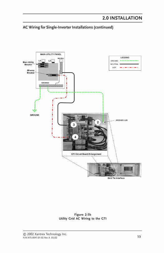
Figure 2-5b Utility Grid AC Wiring to the GTI .......................................................... 13
Figure 2-5c Inverter AC Input Wiring to the GTI ..................................................... 15
Figure 2-5d Inverter AC Output Wiring to the GTI .................................................. 17
Figure 2-5e GTI Wiring to the Sub-Panel ................................................................. 19
Figure 2-6 GTI Communications Cable Location .................................................. 20
Figure 2-7 Connecting the Communications Cable to the Circuit Board ............. 21
Figure 2-8 Wiring Diagram for Dual-Inverter Installations ................................... 23
Figure 2-8a Ground Wiring for Dual-Inverter Installations ..................................... 25
Figure 2-8b Utility Grid AC Wiring to Dual GTIs ..................................................... 27
Figure 2-8c Inverter AC Input and Output Wiring to Dual GTIs ............................ 29
Figure 2-8d GTI Wiring to the Sub-Panel ................................................................. 31
Figure 2-9 Re-wiring Power Panel Installations to include dual GTIs ................... 33
Figure 2-10 Original Power Module Wiring ............................................................. 35
Figure 2-10a Power Module Rewiring for dual GTI Installations .............................. 36

© 2002 Xantrex Technology Inc.P/N 975-0041-01-02 Rev A 03/02 1
1.0 INTRODUCTION
INTRODUCTIONThe Grid Tie Interface (GTI) is an integrated assembly used with the Trace™
SW Series II inverter/charger with Revision 4.2 (or higher) software. This new deviceprovides active anti-islanding protection and reduces current Total HarmonicDistortion (THD) as required in UL-1741-2000.
The Grid Tie Interface is an accessory, which is connected between the grid, theAC loads, and the SW Series II inverter to optimize the “SELL” feature. While thereis a small inductor in the GTI, this device is not a “filter”; rather it contains anadditional control microprocessor, which connects to the SW Series II with acommunications cable.
When the GTI is connected and the Inverter “SELL” mode is selected, themicroprocessor of the GTI takes control of the SW Series II and operates the inverter“SELL” feature. The GTI affords a dedicated microprocessor and new, sophisticatedcontrol algorithms that are able to optimize the sell function.
The SW Series II with the GTI meets all power quality requirements of UL1741,including harmonic distortion, power factor, and anti-islanding requirements. Inaddition, it has increased the SW Series II’s efficiency in SELL mode to within 1% ofthe impressive off-grid efficiency of the SW.
The GTI also contains an automatic transfer/shorting relay, which the SWSeries II uses to disconnect the GTI from the circuit when it is not needed, forexample when the SW Series II is charging batteries from the grid. This is also usedto disconnect the GTI so that it does ��� represent a phantom load or parasiticloss to the system.
All new SW Series II units (manufactured since December of 2001) areequipped to allow the GTI to be installed in the field. The SW Series II inverter isCertified to UL1741 for off grid and backup power applications. The SW can beconnected to the grid as a battery charger; however, it is ��� approved to use theSELL feature (net meter) without the GTI accessory. The GTI carries all necessaryapprovals and markings to allow a safety inspector to approve the installation for netmetering.

1.0 INTRODUCTION
2© 2002 Xantrex Technology Inc.
P/N 975-0041-01-02 Rev A 03/02
Figure 1-1Grid Tie Interface Flow Diagram
1.0 INTRODUCTION
© 2002 Xantrex Technology Inc.P/N 975-0041-01-02 Rev A 03/02 3
Figure 1-2Grid Tie Interface Flow Diagram with External Manual Bypass Switch
1.0 INTRODUCTION
4© 2002 Xantrex Technology Inc.
P/N 975-0041-01-02 Rev A 03/02
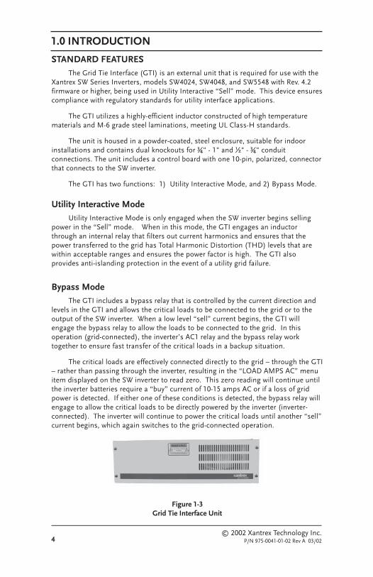
STANDARD FEATURESThe Grid Tie Interface (GTI) is an external unit that is required for use with the
Xantrex SW Series Inverters, models SW4024, SW4048, and SW5548 with Rev. 4.2firmware or higher, being used in Utility Interactive “Sell” mode. This device ensurescompliance with regulatory standards for utility interface applications.
The GTI utilizes a highly-efficient inductor constructed of high temperaturematerials and M-6 grade steel laminations, meeting UL Class-H standards.
The unit is housed in a powder-coated, steel enclosure, suitable for indoorinstallations and contains dual knockouts for ¾" - 1" and ½" - ¾" conduitconnections. The unit includes a control board with one 10-pin, polarized, connectorthat connects to the SW inverter.
The GTI has two functions: 1) Utility Interactive Mode, and 2) Bypass Mode.
Utility Interactive ModeUtility Interactive Mode is only engaged when the SW inverter begins selling
power in the “Sell” mode. When in this mode, the GTI engages an inductorthrough an internal relay that filters out current harmonics and ensures that thepower transferred to the grid has Total Harmonic Distortion (THD) levels that arewithin acceptable ranges and ensures the power factor is high. The GTI alsoprovides anti-islanding protection in the event of a utility grid failure.
Bypass ModeThe GTI includes a bypass relay that is controlled by the current direction and
levels in the GTI and allows the critical loads to be connected to the grid or to theoutput of the SW inverter. When a low level “sell” current begins, the GTI willengage the bypass relay to allow the loads to be connected to the grid. In thisoperation (grid-connected), the inverter’s AC1 relay and the bypass relay worktogether to ensure fast transfer of the critical loads in a backup situation.
The critical loads are effectively connected directly to the grid – through the GTI– rather than passing through the inverter, resulting in the “LOAD AMPS AC” menuitem displayed on the SW inverter to read zero. This zero reading will continue untilthe inverter batteries require a “buy” current of 10-15 amps AC or if a loss of gridpower is detected. If either one of these conditions is detected, the bypass relay willengage to allow the critical loads to be directly powered by the inverter (inverter-connected). The inverter will continue to power the critical loads until another “sell”current begins, which again switches to the grid-connected operation.
Figure 1-3Grid Tie Interface Unit

© 2002 Xantrex Technology Inc.P/N 975-0041-01-02 Rev A 03/02 5
2.0 INSTALLATION
PRE-INSTALLATIONThe GTI is only designed to work with the SW4024, SW4048 and SW5548
models that have revision 4.2 (or higher) software. Prior to installing the GTI,ensure that you have the appropriate model, the proper level of software and theinverter has the communication cable located within.
See Figure 2-6 for the location of this cable.
WARNING: THE CRITICAL LOADS ARE NOWPOWERED THROUGH THE GTI; THESE LOADSWILL NOT BE POWERED IF THE SW INVERTER ORTHE GTI ARE OFF OR DISCONNECTED. IT ISRECOMMENDED THAT AN EXTERNAL BYPASSSWITCH/BREAKER BE INSTALLED BETWEEN THEGRID AND THE CRITICAL LOAD-PANEL. THISSWITCH, WHEN ENGAGED, WILL ALLOW THEGRID TO DIRECTLY POWER THE LOADS WHILETHE GTI OR SW INVERTER IS OFF ORDISCONNECTED. SEE FIGURE 2-9 FOR ANEXAMPLE OF THIS RELAY IN A XANTREX POWERPANEL.
Required Tools and Materials• Wire strippers• Phillips screw driver• Slotted screw driver• Torque wrench• 3/16" Hex-Head wrench• #6 AWG Wire
Removing the Top Cover1. Remove the four Phillips screws and starwashers and set aside. Be sure to
put these screws and washers somewhere where they can’t get lost.
Figure 2-1Removing the Top Cover
����������������� ������ ������������
����������������� ������ ������������

2.0 INSTALLATION
6© 2002 Xantrex Technology Inc.
P/N 975-0041-01-02 Rev A 03/02
Figure 2-2Mounting Holes
�����������
�����������
�����������
�����������
MOUNTINGPlace the GTI in a convenient location, close to the inverter. The GTI must
be mounted horizontally on a flat surface (such as a wall) in a clean, dryenvironment. Do not mount the GTI where it will be exposed to the weather or ina damp location.
NOTE: The GTI weighs approximately 25 pounds. Useappropriate wall anchors or backing material (plywood,2 x 4’s, etc.) that will support its weight.
CAUTION: Do not mount vertically as water mayenter the enclosure and damage the internalcircuitry. Damage caused by mounting the unitvertically is NOT covered under the limitedwarranty.
Procedure1. Use a level and mark the location for mounting the unit on the wall.
2. Measure out the four mounting screw holes according to Figure 2-3.
3. Use a #10 x 3/8 (or 1/2) inch long screw and washer (and appropriateanchors if necessary) and mount the GTI securely to the wall or backingmaterial (plywood, 2 x 4’s, etc.).
4. Remove the appropriate knockouts for the conduit. Install the conduitbetween the GTI and the inverter. Use separate conduit for the AC wiringand the communications cable.

2.0 INSTALLATION
© 2002 Xantrex Technology Inc.P/N 975-0041-01-02 Rev A 03/02 7
Figure 2-3Dimensional Drawing (Not to scale)
Front Internal view of unit
Side of unit
Ends of unit (both ends)
2 3/8"
4 3/8"
1 1/8"
19 7/8"
4 3/4"
3/4"
6 1/8"
1 3/4"
3 1/8"
1 3/8"21"
1 7/8" 1 7/8" 1 7/8"
3 1/5"
1 3/8"
6 1/4"
6 3/4"
18 3/4"

2.0 INSTALLATION
8© 2002 Xantrex Technology Inc.
P/N 975-0041-01-02 Rev A 03/02
Figure 2-4GTI Circuit Board Enlargement
WIRING
AC Wiring for Single-Inverter Installations
NOTE: All wiring should be performed by a qualifiedperson or a licensed electrician.
NOTE: Ensure that wire size and conduit sizes areappropriate for this installation. AC wiring should berouted in separate conduits from the communicationscable.
CAUTION: AC pass-through ability through the GTIis 60 amps. It is recommended to use minimum#6 AWG (THHN) wiring.
See Figure 2-7 for an enlargement of this circuit board showing thelocation of the communications cable port.
���������
������ �������
��� �� ������
��� ����������!����
��� ������������ �� "�
���� ����#��������������!���$� �
%!���&�������!��'
������ �������� &
(� ��)��(

2.0 INSTALLATION
© 2002 Xantrex Technology Inc.P/N 975-0041-01-02 Rev A 03/02 9
Figure 2-5AC Input and Output Wiring for Single-Inverter Installations
AC Wiring for Single-Inverter Installations (continued)See pages 10 through 21 for detailed instructions for AC Input and ACoutput wiring for single-inverter/GTI installations.

2.0 INSTALLATION
10© 2002 Xantrex Technology Inc.
P/N 975-0041-01-02 Rev A 03/02
Wiring (continued)
AC Wiring for Single-Inverter Installations (continued)
Ground Wiring
Note: Ground wiring must be established at each unit.Ground wiring can also be accomplished in a variety ofways. The following instructions describe only onemethod. Please consult your local electrician for specificwiring details pertaining to your installation.
1. Connect a wire from the ground bus in the main service panel to theground lug in the GTI.
2. Connect a wire from the ground bus in the main service panel to theground terminal in the inverter.
3. Connect a wire from the ground bus in the main service panel to theground terminal in the sub-panel.
See Figure 2-5a for an illustration of ground wiring for a single-inverterinstallation with the GTI.

2.0 INSTALLATION
© 2002 Xantrex Technology Inc.P/N 975-0041-01-02 Rev A 03/02 11
Figure 2-5aGround Wiring for a Single-Inverter Installations
AC Wiring for Single-Inverter Installations (continued)

2.0 INSTALLATION
12© 2002 Xantrex Technology Inc.
P/N 975-0041-01-02 Rev A 03/02
Wiring (continued)
AC Wiring for Single-Inverter Installations (continued)
Utility Grid AC Wiring to the GTI
WARNING: DISCONNECT THE BATTERIES FROMTHE INVERTER IF THEY ARE ALREADY CONNECTED.
1. Ensure the breaker that feeds the GTI is OFF (i.e., no power out). Feed theHOT and NEUTRAL input wires from the GTI to the main utility panel.Leave a sufficient amount of extra wire at each end.
2. Confirm a GROUND (green) wire exists from the main utility panel to theGTI’s AC GROUND lug.
3. Connect the NEUTRAL (white) wire from the main utility panel to the GTI’sNEUTRAL bar.
4 . Connect the HOT (BLACK) wire from a single-pole breaker (60 amps) inthe main utility panel to the GTI’s AC1 HOT IN terminal.
5 . Torque all connections to 10 to 15 inch-pounds.
See Figure 2-5b for an illustration of Utility Grid AC Wiring to the GTI.
2.0 INSTALLATION
© 2002 Xantrex Technology Inc.P/N 975-0041-01-02 Rev A 03/02 13
Figure 2-5bUtility Grid AC Wiring to the GTI
AC Wiring for Single-Inverter Installations (continued)

2.0 INSTALLATION
14© 2002 Xantrex Technology Inc.
P/N 975-0041-01-02 Rev A 03/02
Inverter AC Input Wiring to the GTI1. Feed the HOT and NEUTRAL input wires from the inverter to the GTI.
Leave three to six inches of extra wire at each end.
2. Connect the NEUTRAL (white) wire from the GTI’s NEU OUT terminal tothe inverter’s NEUTRAL IN 1 terminal.
3 . Connect the AC1 HOT OUT (BLACK) wire from the GTI to the inverter’sAC1 HOT IN terminal.
4 . Torque all connections to 10 to 15 inch-pounds.
See Figure 2-5c for an illustration of the inverter AC input wiring to theGTI.
Wiring (continued)
AC Wiring for Single-Inverter Installations (continued)

2.0 INSTALLATION
© 2002 Xantrex Technology Inc.P/N 975-0041-01-02 Rev A 03/02 15
AC Wiring for Single-Inverter Installations (continued)
Figure 2-5cInverter AC Input Wiring to the GTI

2.0 INSTALLATION
16© 2002 Xantrex Technology Inc.
P/N 975-0041-01-02 Rev A 03/02
Inverter AC Output Wiring to the GTI
WARNING: ENSURE THE SUB-PANEL DOES NOTHAVE A NEUTRAL-TO-GROUND BOND. IF ITDOES, REMOVE IT. ALL AC NEUTRAL-GROUNDBONDING IS DONE AT THE MAIN UTILITY PANEL.
1. Connect a NEUTRAL (white) wire to the inverters’s NEUTRAL OUTterminal.
2 . Connect the other end of this same NEUTRAL wire to the NEUTRAL bar inthe GTI.
3. Connect a HOT (Black) wire to the inverter’s terminal labeled AC HOTOUTPUT.
4. Connect the other end of the HOT (black) wire from the inverer’s AC HOTOUT terminal to the GTI’s HOT IN terminal.
5. Torque all connections to 10 to 15 inch-pounds.
See Figure 2-5d for an illustration of the inverter AC output wiring tothe GTI.
Wiring (continued)
AC Wiring for Single-Inverter Installations (continued)

2.0 INSTALLATION
© 2002 Xantrex Technology Inc.P/N 975-0041-01-02 Rev A 03/02 17
Figure 2-5dInverter AC Output Wiring to the GTI
AC Wiring for Single-Inverter Installations (continued)

2.0 INSTALLATION
18© 2002 Xantrex Technology Inc.
P/N 975-0041-01-02 Rev A 03/02
Wiring (continued)
AC Wiring for Single-Inverter Installations (continued)
GTI Wiring to the Sub-Panel
WARNING: ENSURE THE SUB-PANEL DOES NOTHAVE A NEUTRAL-TO-GROUND BOND. IF ITDOES, REMOVE IT. ALL AC NEUTRAL-GROUNDBONDING IS DONE AT THE MAIN UTILITY PANEL.
1. Connect a NEUTRAL (white) wire to the GTI’s NEUTRAL bar.
2. Connect the other end of this NEUTRAL wire to the NEUTRAL bar in thesub-panel.
3. Connect the HOT (black) wire to the GTI’s AC HOT OUT terminal.
4. Connect the other end of this HOT (black) wire to the sub-panels HOT INterminal.
5. Torque all the inverter’s connections to 10 to 15 inch-pounds.
NOTE: Consult the sub-panel manufacturer’sspecifications for wire torques on the sub-panelconnections. Use those torque requirements if different.

2.0 INSTALLATION
© 2002 Xantrex Technology Inc.P/N 975-0041-01-02 Rev A 03/02 19
AC Wiring for Single-Inverter Installations (continued)
Figure 2-5eGTI Wiring to the Sub-Panel
2.0 INSTALLATION
20© 2002 Xantrex Technology Inc.
P/N 975-0041-01-02 Rev A 03/02
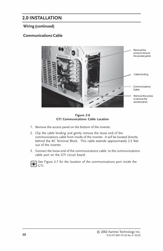
Wiring (continued)
Communications Cable
Figure 2-6GTI Communications Cable Location
1. Remove the access panel on the bottom of the inverter.
2. Clip the cable binding and gently remove the loose end of thecommunications cable from inside of the inverter. It will be located directlybehind the AC Terminal Block. This cable extends approximately 2.5 feetout of the inverter.
3. Connect the loose end of the communications cable to the communicationscable port on the GTI circuit board.
See Figure 2-7 for the location of the communications port inside theGTI.
��������������!��
������������ ������ ��������������������*
������������� ����� ��������������������*
��!���!�&��
2.0 INSTALLATION
© 2002 Xantrex Technology Inc.P/N 975-0041-01-02 Rev A 03/02 21
Wiring (continued)
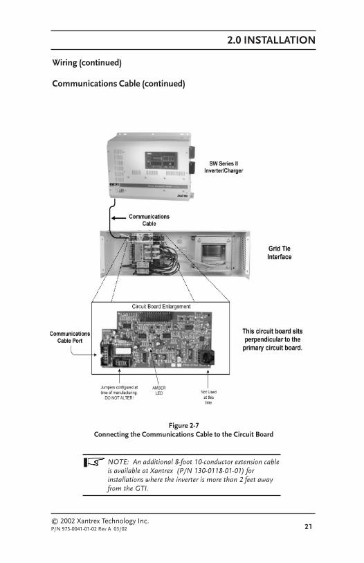
Communications Cable (continued)
Figure 2-7Connecting the Communications Cable to the Circuit Board
NOTE: An additional 8-foot 10-conductor extension cableis available at Xantrex (P/N 130-0118-01-01) forinstallations where the inverter is more than 2 feet awayfrom the GTI.
2.0 INSTALLATION
22© 2002 Xantrex Technology Inc.
P/N 975-0041-01-02 Rev A 03/02
Wiring (continued)
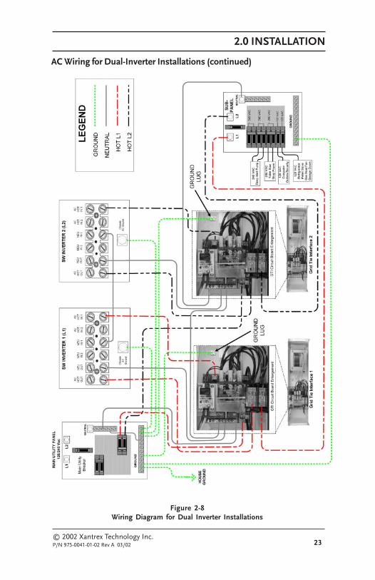
AC Wiring for Dual-Inverter InstallationsSeries stacking is used in applications where either 240-volt loads (or a
combination of both 240- and 120-volt loads) need to be powered from the inverters.One inverter, connected to the utility’s L1 line, provides one 120 volt AC output anda second inverter connected to the utility’s L2 line provides the second 120 volt ACoutput (180 degrees out-of-phase from the first inverter). The combined out-of-phase voltages can power 240 volt AC loads as well as 120 volt loads, up to thepower rating of the inverters.
NOTE: For full pass-through capability of the inverter,#6 AWG (90°C) minimum is recommended. Protect thewire with an appropriately sized breaker.
See Figure 2-8 for a an illustration of input and output wiring for dual-inverters with dual GTI installations.
See pages 24 through31 for detailed instructions for AC Input and ACoutput wiring for dual-inverter/GTI installations.
2.0 INSTALLATION
© 2002 Xantrex Technology Inc.P/N 975-0041-01-02 Rev A 03/02 23
Figure 2-8Wiring Diagram for Dual Inverter Installations
AC Wiring for Dual-Inverter Installations (continued)

2.0 INSTALLATION
24© 2002 Xantrex Technology Inc.
P/N 975-0041-01-02 Rev A 03/02
Wiring (continued)
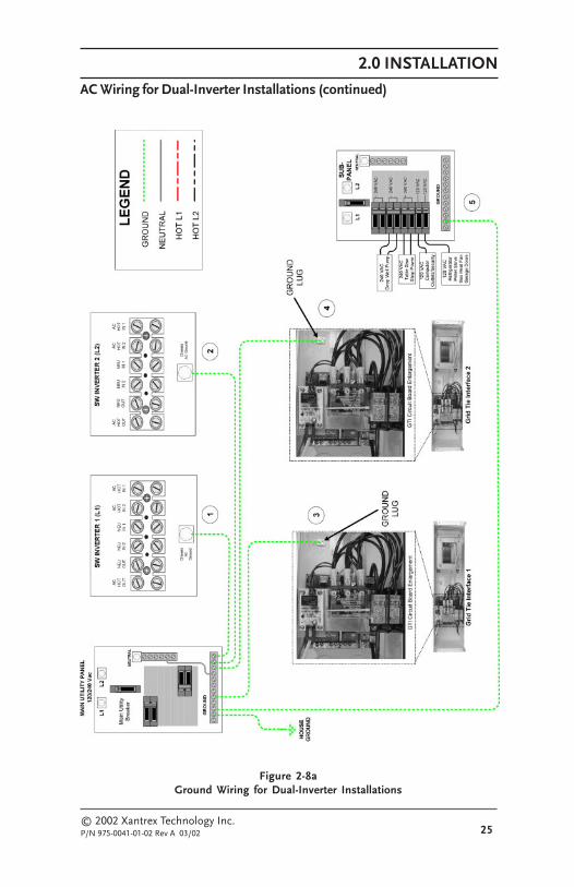
AC Wiring for Dual-Inverter Installations (continued)
Ground Wiring1. Ensure there is a ground wire from inverter-1 to the main service panel.
2. Ensure there is a ground wire from inverter-2 to the main service panel.
3. Connect a wire from the ground bus in the main service panel to theGROUND terminal in the GTI-1.
4. Connect a wire from the ground bus in the main service panel to theGROUND terminal in the GTI-2.
5. Connect a wire from the ground bus in the main service panel to theGROUND terminal in the sub-panel.
See Figure 2-8a for an illustration of the ground wiring for dual-inverter/dual-GTI installations.
2.0 INSTALLATION
© 2002 Xantrex Technology Inc.P/N 975-0041-01-02 Rev A 03/02 25
Figure 2-8aGround Wiring for Dual-Inverter Installations
AC Wiring for Dual-Inverter Installations (continued)
2.0 INSTALLATION
26© 2002 Xantrex Technology Inc.
P/N 975-0041-01-02 Rev A 03/02
Wiring (continued)
AC Wiring for Dual-Inverter Installations (continued)
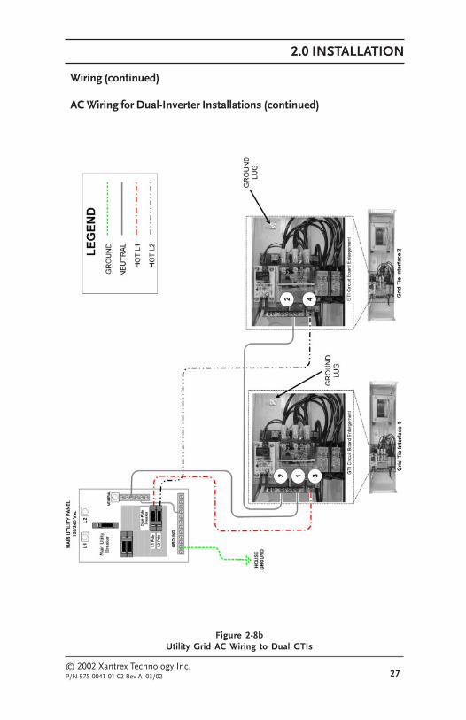
Utility Grid AC Wiring to Dual GTIs1. Connect a wire from the neutral bus in the main service panel to the
NEUTRAL bar in the GTI-1.
2. Connect a wire to the NEUTRAL bar on the GTI-1 and route this wire to theGTI-2’s NEUTRAL bar. Keep this wire as short as possible.
3. Select a dual-pole breaker in the main service panel. Connect a wire fromthe L1-pole of the selected breaker to the GTI-1’s AC HOT IN terminal.
4. Connect a wire from the L2 pole of the same dual-pole breaker to the GTI-2’s AC HOT IN terminal.
See Figure 2-8b for an illustration of AC wiring from the utility grid tothe GTIs.
2.0 INSTALLATION
© 2002 Xantrex Technology Inc.P/N 975-0041-01-02 Rev A 03/02 27
Figure 2-8bUtility Grid AC Wiring to Dual GTIs
Wiring (continued)
AC Wiring for Dual-Inverter Installations (continued)

2.0 INSTALLATION
28© 2002 Xantrex Technology Inc.
P/N 975-0041-01-02 Rev A 03/02
Wiring (continued)
AC Wiring for Dual-Inverter Installations (continued)
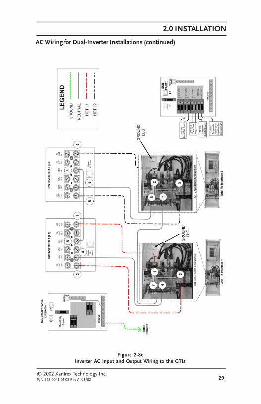
Inverter AC Input and Output Wiring to the GTIsThe output of each inverter provides 120 Vac. The voltage between the HOT
outputs from the L1 and L2 inverter is 240 Vac.
NOTE: Both inverter AC IN and inverter AC OUT willbe wired to the GTIs.
1. Connect a wire from the GTI-1’s AC HOT OUT to the L1 inverter’sAC HOT IN 1 terminal.
2. Connect a wire from the GTI-2’s AC HOT OUT to the L2 inverter’sAC HOT IN 1 terminal.
3. Connect the AC HOT OUTPUT (120 Vac) from the L1 inverter to the AC INterminal in the GTI-1.
4. Connect the NEUTRAL wire from the L1 inverter’s NEUTRAL OUT terminalto the neutral bar in the GTI-1.
5. Connect the AC HOT OUTPUT (120 Vac) from the L2 inverter to the AC INterminal in the GTI-2.
6. Connect the NEUTRAL wire from the L2 inverter’s NEUTRAL OUT terminalto the neutral bar in the GTI-2.
7. Connect a wire from the NEUTRAL bar in GTI-1 to the NEUTRAL bar inGTI-2.
8. Ensure a NEUTRAL wire exists from the L1 inverter NEUTRAL IN 1 terminalto the L2 inverter NEUTRAL IN 1 terminal.
See Figure 2-8c for an illustration of AC wiring from the inverters to theGTIs.
2.0 INSTALLATION
© 2002 Xantrex Technology Inc.P/N 975-0041-01-02 Rev A 03/02 29
Figure 2-8cInverter AC Input and Output Wiring to the GTIs
AC Wiring for Dual-Inverter Installations (continued)

2.0 INSTALLATION
30© 2002 Xantrex Technology Inc.
P/N 975-0041-01-02 Rev A 03/02
Wiring (continued)
AC Wiring for Dual-Inverter Installations (continued)
GTI Wiring to the Sub-Panel1. Connect a NEUTRAL wire from GTI-2’s NEUTRAL bar to the NEUTRAL
bar in the sub-panel.
2. Connect the AC OUTPUT (120 Vac) from GTI-1 to the L1 terminal in thesub-panel.
3. Connect the AC OUTPUT (120 Vac) from the GTI-2 to the L2 terminal inthe sub-panel.
WARNING: ENSURE THE ONLY NEUTRAL-TO-GROUND BOND IS IN THE MAIN UTILITY PANEL.REMOVE ANY BONDING FROM THE SUB-PANEL IFIT IS PRESENT.
See Figure 2-8d for an illustration of GTI Wiring to the Sub-Panel.
Connecting the Communications Cables for Dual Inverter InstallationsSee Figure 2-6 for the location of the communications cable inside theSW inverters.
See Figure 2-7 for the location of the communications port on the GTIcircuit board.
NOTE: The communications cables are notinterchangeable. Make sure that you connect thecommunications cable from the inverter to the GTI thathas that inverter’s AC HOT IN 1 connection.
1. Connect the communications cable from inverter 1 to thecommunications port on GTI-1.
2. Connect the communications cable from inverter 2 to thecommunications port on GTI-2.

2.0 INSTALLATION
© 2002 Xantrex Technology Inc.P/N 975-0041-01-02 Rev A 03/02 31
Figure 2-8dGTI Wiring to the Sub-Panel
AC Wiring for Dual-Inverter Installations (continued)

2.0 INSTALLATION
32© 2002 Xantrex Technology Inc.
P/N 975-0041-01-02 Rev A 03/02
Wiring (continued)
AC Rewiring for Dual-Inverter Power Panel Installations
NOTE: The following procedure is for a dual-inverterpower panel system. If your system is only a single-inverter power panel system, disregard the steps thatrefer to components that are not present.
NOTE: Use appropriate sized wire and circuit breakers(if needed) for all wiring added to the installation.THHN #6 AWG wire is recommended.
1. Inside the power panel, locate and label wires 1A and 1C from inverter-1and wires 2A and 2C from inverter-2 as labeled in Figure 2-9.
2. Inside the power panel, locate and label terminals 1B, 1D, 2B and 2D aslabeled in Figure 2-9.
3. Inside each GTI, locate and label the terminals 1B, 1D, 2B, and 2D aslabeled in Figure 2-9.
4. Remove wire 1A from terminal 1B in the power panel.
a. Use a wire nut to add a sufficient length of wire to wire 1A to reachterminal 1A in GTI-1.
b. Connect the extended wire 1A to terminal 1A in GTI-1.
5. Remove wire 1C from terminal 1D in the power panel.
a. Use a wire nut to add a sufficient length of wire to wire 1C to reachterminal 1C in GTI-1.
b. Connect the extended wire 1C to terminal 1C in GTI-1.
6. Remove wire 2A from terminal 2B in the power panel.
a. Use a wire nut to add a sufficient length of wire to wire 2A to reachterminal 2A in GTI-1.
b. Connect the extended wire 2A to terminal 2A in GTI-2.
7. Remove wire 2C from terminal 2D in the power panel.
a. Use a wire nut to add a sufficient length of wire to wire 2C to reachterminal 2C in GTI-1.
b. Connect the extended wire 2C to terminal 2C in GTI-2.
8. Add a neutral wire (NEU) to the NEUTRAL BAR in GTI-1 and connect it tothe NEUTRAL BAR in GTI-2.
9. Add a neutral wire (NEU) to the NEUTRAL BAR (NEU) in the power paneland connect it to either GTI-1 or GTI-2.
10. Add a wire to terminal 1B in the power panel and connect it to terminal 1Bin GTI-1.
11. Add a wire to terminal 1D in the power panel and connect it to terminal1D in GTI-1.
12. Add a wire to terminal 2B in the power panel and connect it to terminal2B in GTI-2.
13. Add a wire to terminal 2D in the power panel and connect it to terminal2D in GTI-2.

2.0 INSTALLATION
© 2002 Xantrex Technology Inc.P/N 975-0041-01-02 Rev A 03/02 33
Figure 2-9Rewiring Power Panel Installations to include dual GTIs
AC Re-Wiring for Power Panel Installations (continued)

2.0 INSTALLATION
34© 2002 Xantrex Technology Inc.
P/N 975-0041-01-02 Rev A 03/02
Wiring (continued)
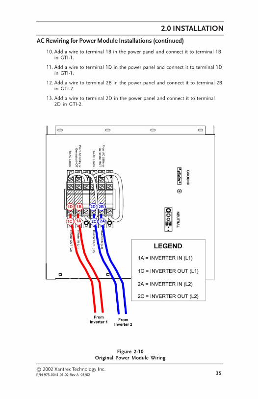
AC Rewiring for Power Module Installations
NOTE: The following procedure is for a dual-inverterpower module system. If your system is only a single-inverter power module system, disregard the steps thatrefer to components that are not present.
See Figure 2-10 for an illustration of the original power module wiring.
See Figure 2-10a for an illustration of the power module re-wiring.
NOTE: Use appropriate sized wire and circuit breakers(if needed) for all wiring added to the installation.THHN #6 AWG wire is recommended.
1. Inside the power module, locate and label wires 1A and 1C from inverter-1and wires 2A and 2C from inverter 2 as labeled in Figure 2-10.
2. Inside the power module, locate and label terminals 1B, 1D, 2B and 2D aslabeled in Figure 2-10.
3. Inside each GTI, locate and label the terminals 1B, 1D, 2B, and 2D aslabeled in Figure 2-10a.
4. Remove wire 1A from terminal 1B in the power module.
a. Use a wire nut to add a sufficient length of wire to wire 1A to reachterminal 1A in GTI-1.
b. Connect the extended wire 1A to terminal 1A in GTI-1.
5. Remove wire 1C from terminal 1D in the power module.
a. Use a wire nut to add a sufficient length of wire to wire 1C to reachterminal 1C in GTI-1.
b. Connect the extended wire 1C to terminal 1C in GTI-1.
6. Remove wire 2A from terminal 2B in the power module.
a. Use a wire nut to add a sufficient length of wire to wire 2A to reachterminal 2A in GTI-2.
b. Connect the extended wire 2A to terminal 2A in GTI-2.
7. Remove wire 2C from terminal 2D in the power module.
a. Use a wire nut to add a sufficient length of wire to wire 2C to reachterminal 2C in GTI-2.
b. Connect the extended wire 2C to terminal 2C in GTI-2.
8. Add a neutral wire (NEU) to the NEUTRAL BAR in GTI-1 and connect it tothe NEUTRAL BAR in GTI-2.
9. Add a neutral wire (NEU) to the NEUTRAL BAR (NEU) in the powermodule and connect it to either GTI-1 or GTI-2.
2.0 INSTALLATION
© 2002 Xantrex Technology Inc.P/N 975-0041-01-02 Rev A 03/02 35
Figure 2-10Original Power Module Wiring
AC Rewiring for Power Module Installations (continued)
10. Add a wire to terminal 1B in the power panel and connect it to terminal 1Bin GTI-1.
11. Add a wire to terminal 1D in the power panel and connect it to terminal 1Din GTI-1.
12. Add a wire to terminal 2B in the power panel and connect it to terminal 2Bin GTI-2.
13. Add a wire to terminal 2D in the power panel and connect it to terminal2D in GTI-2.

2.0 INSTALLATION
36© 2002 Xantrex Technology Inc.
P/N 975-0041-01-02 Rev A 03/02
Figure 2-10aPower Module Re-wiring for dual GTI Installations
Wiring (continued)
AC Rewiring for Power Module Installations (continued)

2.0 INSTALLATION
© 2002 Xantrex Technology Inc.P/N 975-0041-01-02 Rev A 03/02 37
WIRING CHECKBefore powering on the GTI, recheck all wiring and ensure it is connected to
the proper terminals. Check that the ground and neutral connections areproperly wired and tight.
After all the wiring has been checked, install the front cover and secure itwith the four phillips screws removed in the beginning of the installation.
OPERATING STACKED INVERTERSStacked inverters must operate together in order to provide the 120/240 Vac
to the loads. The Series Stacking Interface cable ensures the output from eachinverter is 180 degrees out-of-phase for operating 240 Vac loads.
NOTE: Until the units are tested, do not connect loadsto the inverters 120 or 240 Vac output.
START-UP AND TEST1. Ensure the main service panel’s circuit breakers feeding the inverters are
OFF.
2. Switch ON both inverters. The inverter should be providing 120/240 Vacto the sub-panel.
3. Use an AC voltmeter and measure the voltage between the L1 terminal andneutral bus in the sub-panel. This voltage should be 120 Vac (± 3%).
4. Measure the voltage between the L2 terminal and neutral bus in the sub-panel. This voltage should be 120 Vac (± 3%).
5. Measure the voltage between the L1 and L2 terminals in the sub-panel.This voltage should be 240 Vac (± 3%).
6. Switch ON the main service panel’s circuit breakers feeding the inverters.
7. Verify the inverters are charging the batteries and powering the sub-panel(refer to the operator’s manual).
8. Switch both inverters OFF.
9. Replace all covers and panels on the inverters and sub-panel.
The stacked inverter system is now ready for use.
NOTE: If the inverters are not operating properly, pleaserefer to the operator’s manual for setup andtroubleshooting information.

2.0 INSTALLATION
38© 2002 Xantrex Technology Inc.
P/N 975-0041-01-02 Rev A 03/02
Notes:

© 2002 Xantrex Technology Inc.P/N 975-0041-01-01 Rev A 01/02 39
3.0 TROUBLESHOOTING
Table 3-1Troubleshooting Guidelines for the Grid Tie Interface
motpmyS noitcAdednemmoceR noituloseR
tonsimetsysehTehtotrewopgnillesretrevniehtdnadirg.gnihsalfsiDEL1CA
.nosiretrevniehterusnE .noretrevniehtnruT
tonsimetsysehTehtotrewopgnillesretrevniehtdnadirg
.ffosiDEL1CA
ITGdnaretrevniehtotgniriwkcehC.tupni .gniriwCAehttcerroC
CAehtgnikcehcretfA:gniriw
tonllitssimetsysehTehtotrewopgnillesretrevniehtdnadirg
.ffosiDEL1CA
ehtkcehcdnarevocITGehtevomeR.draobtiucriclacitrevehtnoDEL
fonoitacolehtrof7-2erugiFeeS.DELeht
dnaegatloveht,NOsiDELITGehtfI.tneserperaycneuqerf .tinuehthtiwmelborponsierehT
dnaegatloveht,gnihsalfsiDELITGehtfInihtiwtontub,tneserperaycneuqerf
.stimilLUelbatpecca
DELeht,yaledetunim-5aretfAsahrewopdirgehtfinonrutlliw.stimilelbatpeccanihtiwdenruter
dnaegatloveht,ffosiDELITGehtfIITGehttatneserptoneraycneuqerf
.tupni
CAdnarekaerbtupniehtkcehC.gniriw

3.0 TROUBLESHOOTING
© 2002 Xantrex Technology Inc.P/N 975-0041-01-01 Rev A 01/02
40
Notes:
© 2002 Xantrex Technology Inc.P/N 975-0041-01-02 Rev A 03/02 A-1
APPENDIX A – SPECIFICATIONS
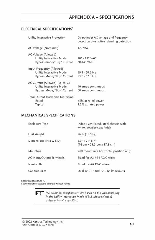
ELECTRICAL SPECIFICATIONS1
Utility Interactive Protection Over/under AC voltage and frequencydetection plus active islanding detection
AC Voltage (Nomimal) 120 VAC
AC Voltage (Allowed)Utility Interactive Mode 106 - 132 VACBypass mode/”Buy” Current 80-149 VAC
Input Frequency (Allowed)Utility Interactive Mode 59.3 - 60.5 HzBypass Mode/”Buy” Current 53.0 - 67.0 Hz
AC Current (Allowed) (@ 25°C)Utility Interactive Mode 40 amps continuousBypass Mode/”Buy” Current 60 amps continuous
Total Output Harmonic DistortionRated <5% at rated powerTypical 2.5% at rated power
MECHANICAL SPECIFICATIONS
Enclosure Type Indoor, ventilated, steel chassis withwhite, powder-coat finish
Unit Weight 26 lb (15.9 kg)
Dimensions (H x W x D) 6.3" x 21" x 7"(16 cm x 53.3 cm x 17.8 cm)
Mounting wall mount in a horizontal position only
AC Input/Output Terminals Sized for #2-#14 AWG wires
Neutral Bar Sized for #6 AWG wires
Conduit Sizes Dual ¾" - 1" and ½" - ¾" knockouts
������������� �����������������������������������������������
1All electrical specifications are based on the unit operatingin the Utility Interactive Mode (SELL Mode selected)unless otherwise specified.

© 2002 Xantrex Technology Inc.P/N 975-0041-01-02 Rev A 03/02A-2
© 2002 Xantrex Technology Inc.P/N 975-0041-01-01 Rev A 01/02 B-1
APPENDIX B – PRODUCT AND SYSTEM INFORMATION
WARRANTYXantrex Technology Inc., warrants its power products against defects in
materials and workmanship for a period of two (2) years from the date of purchase,established by proof of purchase or formal warranty registration, and extends thiswarranty to all purchasers or owners of the product during the warranty period.Xantrex does not warrant its products from any and all defects:
• arising out of material or workmanship not provided by Xantrex or itsAuthorized Service Centers;
� when the product is installed or exposed to an unsuitable environment asevidenced by generalized corrosion or biological infestation;
� resulting from abnormal use of the product, alteration, or use in violation ofthe instructions;
• in components, parts, or products expressly warranted by another manufac-turer.
Xantrex Technology Inc., agrees to supply all parts and labor to repair or replacedefects covered by this warranty with parts or products of original or improveddesign, at the company's option. Xantrex Technology Inc., also reserves the right toimprove the design of its products without obligation to modify or upgrade thosepreviously manufactured. Defective products must be returned to XantrexTechnology Inc., or its Authorized Service Center in the original packaging orequivalent. The cost of transportation and insurance on items returned for service isthe responsibility of the customer. Return transportation (UPS Ground orequivalent) as well as insurance on all repaired items is paid by Xantrex TechnologyInc.
All remedies and the measure of damages are limited to the above. XantrexTechnology Inc., shall in no event be liable for consequential, incidental, contingent,or special damages, even if Xantrex Technology Inc., has been advised of thepossibility of such damages. Any and all other warranties, expressed or implied,arising by law, course of dealing, course of performance, usage of trade or otherwise,including, but not limited to, implied warranties of merchantability and fitness for aparticular purpose, are limited in duration for a period of two (2) years from theoriginal date of purchase.
Some states or countries do not allow limitations on the term of an impliedwarranty, or the exclusion or limitation of incidental or consequential damage, whichmeans the limitations and exclusions of this warranty may not apply to you. Eventhough this warranty gives you specific legal rights, you may also have other rightswhich vary from state to state.

APPENDIX B – PRODUCT & SYSTEM INFORMATION
© 2002 Xantrex Technology Inc.P/N 975-0041-01-01 Rev A 01/02B-2
RETURN MATERIAL AUTHORIZATION POLICYYou must obtain a Return Material Authorization (RMA) number from Xantrex
before returning a product directly to Xantrex. Products returned without an RMAnumber or shipped collect will be refused. When you contact Xantrex to obtainservcie, be prepared to supply the serial number of your product and its date ofpurchase as well as information about the installation and use of the unit.
Return Material ProcedureIf you are returning a product, follow this procedure:
1. Obtain an RMA number and a shipping address from Xantrex.
2. Package the unit safely, preferably using the original box and packingmaterials. Include the following:
• The RMA number• A copy of your dated proof of purchase• A return address where the repaired unit can be shipped• A contact telephone number• A brief description of the problem
3. Ship the unit freight prepaid to the address provided in step 1.

APPENDIX B – PRODUCT & SYSTEM INFORMATION
© 2002 Xantrex Technology Inc.P/N 975-0041-01-01 Rev A 01/02 B-3
SERVICE INFORMATIONXantrex Technology Inc., takes great pride in its products and makes every
effort to ensure your unit fully meets your independent powering needs.
If your product needs repair, contact our Customer Service department at:(360) 435.8826 to obtain an RMA# and shipping information.
Please provide:
Model Number: _____________________________________
Serial Number: _____________________________________
Purchase Date: _____________________________________
Problem: ___________________________________________
Include a telephone number where you can be reached during business hoursand a complete return shipping address (P.O. Box numbers are not acceptable).
Name: _______________________________________________
Address: _____________________________________________
City: ________________________________________________
State / Province: _______________________________________
Zip / Postal Code: _____________________________________
Country: _____________________________________________
Phone: (____) _________________________________________
FAX: (____) __________________________________________
E-mail Address: _______________________________________

APPENDIX B – PRODUCT & SYSTEM INFORMATION
© 2002 Xantrex Technology Inc.P/N 975-0041-01-01 Rev A 01/02B-4


![Supercharger Kit for Peugeot 306 GTI-6 & Rallye …lynxpowerengineering.co.uk/sckitguidelines.pdfSupercharger Kit for Peugeot 306 GTI-6 & Rallye [XU10 J4RS Engine] Installation Guidelines](https://static.fdocuments.us/doc/165x107/5abb5d727f8b9a76038c9dc0/supercharger-kit-for-peugeot-306-gti-6-rallye-kit-for-peugeot-306-gti-6-rallye.jpg)