
GRUNDFOS PRODUCT GUIDE - Amazon S3 · • manual restart • automatic restart. Automatic restart...
106
GRUNDFOS PRODUCT GUIDE SP Submersible pumps, motors, and accessories 60 Hz
Transcript of GRUNDFOS PRODUCT GUIDE - Amazon S3 · • manual restart • automatic restart. Automatic restart...

GRUNDFOS PRODUCT GUIDE
SPSubmersible pumps, motors, and accessories
60 Hz

Ta
ble
of c
on
ten
ts
2
SP
1. Product introduction 3Introduction 3Applications 3Features and benefits 3Identification 8
2. Product overview 9Performance range 60 Hz 9Pump range 10Motor range 10Motor protection and controllers 10
3. Construction 11
4. Operating conditions 18Operating conditions 18Curve conditions 18
5. How to read the curve charts 19
6. Curve charts and technical data 205S (5 gpm) 207S (7 gpm) 2210S (10 gpm) 2416S (16 gpm) 2625S (25 gpm) 2840S (40 gpm) 3060S (60 gpm) 3275S (75 gpm) 3485S (85 gpm) 36150S (150 gpm) 42230S (230 gpm) 48300S (300 gpm) 54385S (385 gpm) 60625S (625 gpm) 70800S (800 gpm) 751100S (1100 gpm) 80Electrical data 85
7. Accessories 86MP 204 86Control functions 89G100 gateway for communication with Grundfos products 92Connecting pieces 94Zinc anodes 95SA-SPM 5 control boxes 96Pt100 97
8. Energy consumption 98Energy consumption of submersible pumps 98
9. Cables 99Cable sizing chart 100
10. Friction loss tables 102
11. Further product documentation 104WebCAPS 104WinCAPS 105

Pro
du
ct
intr
od
uc
tio
n
SP 1
1. Product introduction
IntroductionThe Grundfos SP range of submersible pumps is renowned for high efficiency and reliability. Made entirely of corrosion resistant stainless steel, SP pumps are ideal for a wide variety of applications.
Grundfos SP pumps represent state-of-the-arthydraulic design. Built to deliver optimum efficiency during periods of high demand, SP pumps provide low long-term costs and high operating reliabilityregardless of the application.
The SP range offers high efficiency, high resistance to sand and other abrasives, motor burnout protection, and easy maintenance. A complete monitoring and control system is available for constant optimization of the pumping system.
Fig. 1 Grundfos SP pumps
ApplicationsGrundfos Large SP submersible pumps are suitable for:
• Groundwater supply to waterworks
• Irrigation in horticulture and agriculture
• Groundwater lowering (dewatering)
• Pressure boosting
• Industrial applications
• Domestic water supply.
Pumped liquidsGrundfos SP pumps are suitable for pumping clean, thin, non-aggressive liquids without solid particles or fibers.
SP offers stainless steel construction which ensures good wear resistance and a reduced risk of corrosion where the water has minor chloride content.
Optional, upgraded stainless steel construction is available for pumping more aggressive liquids:
A complete range of zinc anodes for cathodicprotection is available; see p. 97 for applications(for example, sea water applications).
For slightly polluted liquids (for example, containing oil), Grundfos offers a complete range of stainless steel SP NE pumps with all rubber parts made of FKM.
Features and benefitsGrundfos SP submersible pumps offer these features and benefits:
• State-of-the-art hydraulics provide high efficiency and low operating costs
• 100 % stainless steel components inside andoutside for long service life
• Sand resistant
• Resistant to aggressive water
• Motor burnout protection via CU 301
• Dry-running protection
• Monitoring, protection and communication viaprotection unit MP204, and remote control, R100.
TM
05
00
51
06
11
3

Pro
du
ct in
trod
uc
tion
SP1
4
A wide pump rangeGrundfos offers energy-efficient SP submersible pumps with a performance range of up to1,400 gpm and 2,100 ft of head.
The pump range consists of many pump sizes, and each pump size is available with an optional number of stages to match any duty point.
High pump efficiency
Often pump efficiency is given less consideration than the price of a pump; however, owners who chooseefficiency will find substantial savings in energy costs over time. See fig. 2 for an illustration of SPefficiencies in relation to flow.
Example
For example, a pump and motor with a 10 % higher efficiency than a cheaper, less efficient pump, can save its owner more than $80,000.00 over 10 years*.* If producing 880 gpm at 325 ft of head for 10 years @ 13.8 cents per kWh. U.S. kWh costs range from 6 cents to more than 20 cents,depending on region.
Fig. 2 SP pump/motor efficiencies in relation to flow
Pump designGrundfos SP submersible pumps feature components that contribute to the superior performance anddurability of the range.
Lower installation costs
Stainless steel means low weight for ease in thehandling of pumps, resulting in lower equipment costs and reduced installation and service time.
Bearings with sand channels
All bearings are water-lubricated and have a squared shape enabling sand particles, if any, to leave the pump together with the pumped liquid.
Fig. 3 Bearing
Inlet strainer
The inlet strainer prevents particles over a certain size from entering the pump.
Fig. 4 Fig. Inlet strainer
Non-return valve
All pumps are equipped with a reliable check valve in the valve casing preventing back flow in connection with pump stoppage.
Furthermore, the short closing time of the check valve means that the risk of destructive water hammer is reduced to a minimum.
The valve casing is designed for optimum hydraulic properties to minimize the pressure loss across the valve and thus to contribute to the high efficiency of the pump.
Fig. 5 Check valve
TM
05
00
57
07
11
2 3 5 1010 20 30 50 100100 200 500 10001000 2000Q [US GPM]
0
10
20
30
40
50
60
70
80
90
100[%]Eff
60 HZ
85S
150S
230S 30
0S
1100
S
385S
10S
16S
25S
40S
75S
5S
625S
800S
475S
TM
00
73
01
10
96
TM
00
73
02
10
96
TM
01
24
99
17
98
Valve flap

Pro
du
ct
intr
od
uc
tio
n
SP 1
Priming screw
All Grundfos 4" pumps are fitted with a priming screw. Consequently, dry running is prevented, because the priming screw will make sure that pump bearings are always lubricated.
Due to the semi-axial impellers of large SP pumps this priming is provided automatically.
However, it applies to all pump types that if the water table is lowered to a level below the pump inlet neither pump nor motor will be protected against dry running.
Fig. 6 Priming screw
Stop ring
The stop ring prevents damage to the pump during transport and in case of up-thrust in connection with start-up.
The stop ring, which is designed as a thrust bearing, limits axial movements of the pump shaft.
Example: SP 385S
The stationary part of the stop ring (A) is secured in the upper intermediate chamber.
The rotating part (B) is fitted above the split cone (C).
Fig. 7 Stop ring (rotating and stationary part) and the split cone
Grundfos submersible motors
A complete motor range
Grundfos offers a complete submersible motor range in different voltages. For an overview of motor types, sizes and voltages, see page 85.
MS 402 is designed for the domestic ground water market and covers outputs. The MS 4000 and MS6 series are designed for use in a variety ofapplications in water supply. When equipped withfeatures like oversized motor, temperaturemeasurement, cooling jacket, and SiC/SiC mechanical shaft seals, these motors are suitable for heavy-duty industrial applications such as dewatering operations.
As a standard, all external surfaces of the Grundfos MS motors in contact with water are made of AISI 304 stainless steel. For aggressive water, such as seawater or brackish water, R-versions made ofAISI 904 are available.
Grundfos rewindable MMS motor range
Grundfos MMS motors are suitable for anysubmersible installation, including heavy-dutyindustrial applications and dewatering operations (when equipped with temperature control, oversized motor, cooling jacket, and SiC/ SiC mechanical shaft seals).
As a standard the MMS motors are supplied with black cast-iron end-bells. Optionally, the range is available in all-stainless steel AISI 316 or AISI 904 versions.
The 2-pole Grundfos MMS submersible motors are all easy to rewind. The windings of the stator are made of a special water-proof wire of pure electrolytic copper sheathed with special non-hydroscopic thermoplastic material. The fine dielectric properties of this material allow direct contact between the windings and theliquid for efficient cooling of the windings.
Fig. 8 Grundfos MS motors
TM
00
73
04
10
96
TM
01
33
27
04
12
A
B
C
TM
00
73
05
10
96
- G
rA4
011
- G
rA4
01
3
5

Pro
du
ct in
trod
uc
tion
SP1
6
Fig. 9 Grundfos MMS motors
Industrial submersible motors and MS6 T60-versions
For heavy-duty applications Grundfos offers acomplete motor range of industrial motors with up to5 % higher efficiency than that of Grundfos' standard motors. The industrial motors are available in sizes as from 3 Hp up to 30 Hp.
The cooling of the motor is very efficient due to the large motor surface. The efficient cooling makes itpossible to increase the liquid temperature to 140 °F (60 °C) at a minimum flow of 0.49 ft/s (0.15 m/s) past the motor.
The industrial motors are for customers who value low operating costs and long life higher than price.
Grundfos industrial motors are developed for difficult operating conditions. These motors will stand a higher thermal load than standard motors and thus have a longer life when subjected to high load. This applies whether the high load is caused by bad power supply, hot water, bad cooling conditions, high pump load etc.
Please note that heavy duty motors are longer than motors for standard conditions.
Overtemperature protection
Accessories for protection against overtemperature are available for both Grundfos MS and MMSsubmersible motors. When the temperature becomes too high, the protection device will cut out and damage to the pump and motor be avoided.
Restart of the motor after cut-out can be achieved in two ways:
• manual restart
• automatic restart.
Automatic restart means that the MP 204 attempts to restart the motor after 15 minutes. If the first attempt is not successful, restarting will be reattempted at30-minute intervals.
MS
The Grundfos MS submersible motors (with theexception of MS 402) are available with a built-in Tempcon temperature transmitter for protection against overtemperature. By means of the transmitter, it is possible to read out and/or monitor the motortemperature via an MP 204 or a PR 5714 relay.
The Grundfos MS6 submersible motors can be fitted with a Pt100. The Pt100 is fitted in the motor and connected directly to the MP 204 or monitored by the PR 5714 relay.
MMS
For the protection of the Grundfos MMS submersible motors against overtemperature Grundfos offers the Pt100 temperature sensor as an optional extra.
The Pt100 is fitted in the motor and connected directly to the MP 204 or monitored by the PR 5714 relay.
Protection against upthrust
In case of a very low counter pressure in connection with start-up there is a risk that the entire chamber stack may rise. This is called upthrust. Upthrust may damage both pump and motor. Both Grundfos pumps and motors are protected against upthrust as standard, preventing upthrust from occurring during the critical start-up phase. The protection consists of either abuilt-in stop ring or hydraulic balancing.
Built-in cooling chambers
In all Grundfos MS submersible motors, efficientcooling is ensured by cooling chambers at the top and at the bottom of the motor, and by an internal circula-tion of motor liquid.
See fig. 10. As long as the required flow velocity past the motor is maintained, cooling of the motor will be efficient.
TM
01
78
73
47
99

Pro
du
ct
intr
od
uc
tio
n
SP 1
Fig. 10 MS 4000
Lightning protection
The smallest Grundfos submersible motors, such as the MS 402, are all insulated in order to minimize the risk of motor burnout caused by lightning strike.
Reduced risk of short-circuit
The embedded stator winding in the Grundfos MSsubmersible motor is hermetically enclosed instainless steel. The result is high mechanical stability and optimum cooling. Also, this eliminates the risk of short-circuit of the windings caused by watercondensation.
Shaft seal
MS 402
The shaft seal is of the lip seal type characterized by low friction against the rotor shaft.
The rubber material offers good wear resistance, good elasticity and resistance to particles, and it is approved for use in drinking water.
MS 4000, MS6
The material is ceramic/tungsten carbide providing optimum sealing, optimum wear resistance andlong life.
The spring loaded shaft seal is designed with a large surface and a sand shield. The result is a minimum exchange of pumped and motor liquids and nopenetration of particles.
Motors, version R, are supplied with a SiC/SiC shaft seal. Other combinations are available request. See fig. 11 and fig. 12 for an illustration of shaft sealcomponents and configuration.
MMS rewindable motors
The standard shaft seal is a ceramic/carbonmechanical shaft seal. The shaft seal is replaceable.
The material features good wear resistance andresistance to particles.
Together with the shaft seal housing, the sand shield forms a labyrinth seal, which during normal operating conditions prevents penetration of sand particles into the shaft seal.
On request, motors can be supplied with a SiC/SiC seal.
Fig. 11 Shaft seal, MS 4000
Fig. 12 Shaft seal, MS6
TM
00
56
98
09
96
TM
00
73
06
04
12
TM
03
92
25
36
07
7

Pro
du
ct in
trod
uc
tion
SP1
8
Identification
Type key, SP pumps
Type key, MS 402 motors
Type key, MS 4000 motors
Type key, MMS motors
Type key, MS6 motors
Example 475 S 500 - 5 - A B
Rated flow rate in gpm
Type rangeStainless steel parts of materialS= AISI 304N= AISI 316R= AISI 904L
Hp of motor
Number of impellers
First reduced-diameter impeller (A, B or C)
Second reduced-diameter impeller (A, B or C)
Example MS 4 02
Motor submersible
Min. boreholediameter in inches
Generation
- = Stainless steel AISI 304
Example MS 4 000 R
Motor submersible
Min. boreholediameter in inches
Generation
- = Stainless steel AISI 304R = Stainless steel AISI 904LI = Stainless steel AISI 304 + De-rated RE = Stainless steel AISI 904 L + FKMEI = Stainless steel AISI 304 + De-rated + FKM
Example MMS 6 000 N
Type range
Min. boreholediameter in inches
Generation
Material:= Cast iron EN-JL1040
N = DIN/EN 1.4401 (AISI 316)
Example MS 6 R E S W D T60
Type range(Motor Submersible)
Motor diameter in inches
Material• Blank = stainless steel EN 1.4301 (AISI 304)• R = stainless steel EN 1.4539 (AISI 904L)
Rubber parts• Blank = NBR• E = FKM
Shaft seal• Blank = ceramics/carbon• S = SiC/SiC
Radial bearings• Blank = carbon/stainless steel• W = SiC/tungsten carbide
Motor liquid• Blank = SML-3• D = demineralized water
Maximum liquid temperature• T30 = 86 °F (30 °C)• T60 = 140 °F (60 °C)

Pro
du
ct
ov
erv
iew
SP 2
2. Product overview
Performance range 60 Hz
TM
05
00
56
011
24 6 8 10 20 40 60 80 100 200 400 600 1000 2000Q [US GPM]
50
60
80
100
150
200
300
400
500
600
800
1000
1500
2000
3000
[ft]H
11 2 3 4 5 6 7 8 1010 20 30 40 50 60 80 100100 200 Q [m³/h]
16
20
30
40
50
60708090
100100
200
300
400
500
600700800900
[m]H
60 Hz, SF 1.15
625S
800S
385S
300S
85S
1100
S
75S
60S
40S
25S
16S
10S
5S 150S
230S
475S
9

Pro
du
ct o
ve
rvie
w
SP2
10
Pump range
Figures in brackets ( ) indicate connection for pumps with sleeve.
Motor range
Direct-on-line starting is recommended up to 100 hp.
Soft starter or autotransformer is recommended above 100 hp.
Motors with star/delta are available from 7.5 hp.
Motor protection and controllers
Motor protection of single-phase motors, see page 85.
Type 5S 10S 16S 25S 40S 60S 75S 85S 150S 230S 300S 385S 475S 625S 800S 1100S
AISI 304 stainless steel
AISI 316 stainless steel
AISI 904L stainless steel
Connection NPT 1" 1.25" 1.25" 1.5" 2" 2" 2" (3") (3")3"
(4")3"4"
5" 5" 6" 6" 6"
Flange connection:Grundfos flange
5" 5" 6" 6" 6"
Motor output [hp] 0.5 0.75 1.0 1.5 1.5 3.0 5.0 7.5 10.0 15 20 25 30 40 50 60 75 100 125 150 175 200 250
Single-phase
Three-phase
Industrial motor and MS6 T60-versions
Rewindable motor
Steel: AISI 304
Steel: AISI 304and cast iron
Steel: AISI 316
Steel: AISI 904L
Built-in temperaturetransmitter in motor
Motor output [hp] 0.5 0.75 1.0 1.5 1.5 3.0 5.0 7.5 10.0 15 20 25 30 40 50 60 75 100 125 150 175 200 250
MP 204
Pt100
Zinc anode
Vertical flow sleeve
Horizontal flow sleeve
SA-SPM
R100
RS-485 communication module
G100

Co
ns
tru
cti
on
SP 3
3. Construction
Sectional drawing, SP pump, 4"
Fig. 13 SP pump, 4"
Material specification, SP pump, 4"
TM
00
56
06
19
07
6
1
84
19
71
1b
70
2
3
19b
76
13
10
16
18
14
17
64
9
7
8
7
Pos. Component MaterialsStandard
AISI
1 Valve casing Stainless steel 304
1b Discharge piece Stainless steel 304
2 Valve cup Stainless steel 304
3 Valve seat Stainless steel/NBR 304
6 Top bearing NBR
7 Neck ring NBR/PBT
8 Intermediate ring NBR
9Intermediatechamber
Stainless steel 304
10Bottomintermediatechamber
Stainless steel 304
13 Impeller Stainless steel 304
14Suctioninterconnector
Stainless steel 304
16 Shaft Stainless steel 304
17 Strap Stainless steel 304
18 Cable guard Stainless steel 304
19 Hexagon screw Stainless steel 304
19a Nut Stainless steel 316
19b Nut Stainless steel 304
20 Motor cable
64 Priming disc Stainless steel 304
70 Valve guide Stainless steel 304
71 Washer for pos. 19 Stainless steel 316
76 Washer Stainless steel 304
78 Nameplate Stainless steel 316
84 Hook Stainless steel 304
11

Co
ns
truc
tion
SP3
12
Sectional drawing, SP pump, 6"
Fig. 14 SP pump, 6"
Material specification, SP pump, 6"
TM
01
22
58
26
02
1a
13
72
12
14
8a
6
4
3
2
1
19
1715
11
64
25
16
9 8
7
Pos. Component MaterialsStandard N-version R-version
AISI
Valve casing
1 Valve casing Stainless steel 304 316 904 L
2 Valve cup Stainless steel 304 316 904 L
3 Valve seat Stainless steel 304 316 904 L
4 Top chamber Stainless steel 304 316 904 L
Chamber stack
7 Neck ring NBR/PPS
8 Bearing NBR
8a Spacing washerCarbon/graphite HY22 in PTFE mass
9 Chamber Stainless steel 304 316 904 L
11 Nut for split cone Stainless steel 304 316 904 L
12 Split cone Stainless steel 304 316 904 L
13 Impeller Stainless steel 304 316 904 L
16Shaft withcoupling
Stainless steel 431 329 Si 31 803
18 Cable guard Stainless steel 304 316 904 L
23 Rubber guard NBR
25Neck ring retainer
Stainless steel 304 316 904 L
64 Priming screw Stainless steel 304 316 904 L
72 Wear ring Stainless steel 304 316 904 L
Suction interconnector
14Suctioninterconnector
Stainless steel 304 316 904 L
Intermediate piece for 6" motor over40 Hp
Stainless steel 316 316 316
15 Strainer Stainless steel 304 316 904 L
17 Strap Stainless steel 304 316 904 L
19 Nut for strap Stainless steel 304 316 904 L
19a Nut Stainless steel 316 316 316
20 Motor cable
78 Nameplate Stainless steel 316 316 316
Pumps in sleeve
Clamping flange(counter)
Stainless steel 304 316 904 L
Clamping flange Stainless steel 304 316 904 L
Connecting piece
Stainless steel 304 316 904 L
Sleeve Stainless steel 304 316 904 L
Stay bolt Stainless steel 304 316 904 L
Hexagon socket head screw
Stainless steel 304 316 904 L

Co
ns
tru
cti
on
SP 3
Sectional drawing, SP pump, 8"
Fig. 15 SP pump, 8"
Material specification, SP pump, 8"
TM
01
23
59
23
01
8a
11c
17
19
71
7
15
8b
14
18
12
4
6
1372
11
3a
1d
3b
2
39
70
1
3
16
8 9
7
7
8 9
Pos. Component MaterialsStandard N-version R-version
AISI
1 Valve casing Stainless steel 304 316 904L
1d O-ring NBR
2 Valve cup Stainless steel 304 316 904L
3 Valve seatStandard/ N- version: NBRR-version: FKM
3aLower valve seat retainer
Stainless steel 316 316(DIN
1.4517)
3bUpper valve seat retainer
Stainless steel 304 316 904L
4 Top chamber Stainless steel 304 316 904L
6Upper bearing
Stainless steel/NBR
304 316 904L
7 Neck ring NBR/PPS
8 Bearing NBR
8aWasher for stop ring
Carbon/ graphite HY22 in PTFE mass
8b Stop ring Stainless steel 316 316 904L
9 Chamber Stainless steel 304 316 904L
11 Split cone nut Stainless steel 304 316 904L
11cNut for stop ring
Stainless steel 316 316 904L
12 Split cone Stainless steel 304 316 904L
13 Impeller Stainless steel 304 316 904L
14Suction inter-connector
Stainless steel CF8MA744
CD4-MCu(DIN
1.4517)
15 Strainer Stainless steel 304 316 904L
16Shaft complete
Stainless steel 431 329 329
17 Strap Stainless steel 304 316 904L
18 Cable guard Stainless steel 304 316 904L
19 Nut for strap Stainless steel 304 316 904L
39Spring for valve cup
Stainless steel 304 316 SAF 2205
70 Valve guide Stainless steel 304 316 904L
71 Washer Stainless steel 316 316 904L
72 Wear ring Stainless steel 304 316 904L
13

Co
ns
truc
tion
SP3
14
Sectional drawing, SP pump, 10"
Fig. 16 SP pump, 10"
Material specification, SP pump, 10"
TM
01
23
63
27
01
17
19
15
9
14
12
11
8
1372
6
5
3a
1d
3b
2
39
70
1
3
18
7
16
9
4
72
13a13
13b
Pos. Description MaterialStandard N version
AISI
Valve casing
1 Valve casing Stainless steel 304 316
1d O-ring NBR
2 Valve cup Stainless steel 304 316
3 Valve seat Stainless steel 304 316
3aLower valve seat retainer
Stainless steel 304 316
3bUpper valve seat retainer
Stainless steel 304 316
39 Spring for valve cup Stainless steel 301 316
70 Valve guide Stainless steel 304 316
78 Nameplate Stainless steel 304 316
79 Rivet Stainless steel 304 316
63 Connecting piece Stainless steel 304 316
Chamber stack
4 Top chamber Stainless steel 304 316
5 Upthrust discCarbon/graphite HY22 in PTFE mass
6 Top bearingStainless steel/NBR
304 316
7 Neck ring NBR/PPS
8 Bearing NBR
9 Chamber Stainless steel 304 316
11 Nut for split cone Stainless steel 304 316
12 Split cone Stainless steel 304 316
13 Impeller Stainless steel 304 316
16 Shaft with coupling Stainless steel 431 329
18 Cable guard Stainless steel 304 316
18a,18b
Screw for cable guard Stainless steel 304 316
23 Rubber guard NBR
72 Wear ring Stainless steel 304 316
Suction interconnector
14 Suction interconnector Stainless steel 304 316
15 Strainer Stainless steel 304 316
17 Strap Stainless steel 304 316
19 Nut for strap Stainless steel 304 316
19a Nut Stainless steel 316 316
20 Motor cable
22 Bolts Stainless steel 316 316
28,28a
Lock for strainer Stainless steel 329 329

Co
ns
tru
cti
on
SP 3
Sectional drawing - MS motors
Fig. 17 MS 402 motor
Fig. 18 MS 4000 motor
Material specification,MS 402 and MS 4000 motors
R-version motor
TM
00
47
36
04
12
TM
00
78
65
21
96
3
6
5
5
2
1
2
5
5
6
4
3
1
Pos. PartMS 402 MS 4000
AISI
1 Shaft 431 431
2 Shaft seal NBRTungsten carbide/
ceramic
3 Motor sleeve 304 304
4 Motor end shield 304
5 Radial bearing CeramicCeramic/
tungsten carbide
6 Axial bearing Ceramic/carbon Ceramic/carbon
Rubber parts NBR NBR
Pos. Part MS 4000
1 Shaft 318 LN
2 Shaft seal NBR/ceramic
3 Motor sleeve 904L
4 Motor end shield 904L
5 Radial bearing Ceramic/tungsten carbide
6 Thrust bearing Ceramic/carbon
Rubber parts NBR
15

Co
ns
truc
tion
SP3
16
Sectional drawing - MS6 motors
Fig. 19 MS6 motor
Material specification - MS6 motors
R-version motor
TM
03
92
26
36
07
1
2
3
4
Pos. Part MS6
202 Shaft with rotor 318LN
2 Shaft seal Ceramic/carbon
3 Motor sleeve 304
4 Motor end cover 304
Rubber parts NBR/FKM
Pos. Part MS6
1 Shaft 318LN
2 Shaft seal SiC/SiC
3 Motor sleeve 904L
4 Motor end cover (DIN 1.4517)
Rubber parts FKM

Co
ns
tru
cti
on
SP 3
Sectional drawing - MMS motors
Fig. 20 MMS 10000
Material specification
MMS motors, submersible rewindable versions
MMS motors, N- and R-versions
* Only MMS 6000 and MMS 8000 are available in R-versions
TM
01
49
85
04
04
220
204
205
235
202
218
236
206
203
213
212
202a
202a
226
Pos. Component Material AISI
202 Shaft Steel (EN 1.0533)
202a Shaft ends Stainless steel 316/329
203/206
Thrust bearingStationary/rotating part
6", 0.5 - 20 HpHardened steel/EPDM
6", 25 - 50 Hp Ceramic/carbon8" - 10"
204 Bearing bush 6" - 10" Carbon
205 Bearing housing, upper Cast iron A126 Class B
212 Diaphragm CR
213 Motor end shield Cast iron A126 Class B
218 Motor sleeve Stainless steel 304
220 Motor cable EPDM
226 Shaft sealCeramic/carbon
235 Intermediate housing Cast iron A126 Class B
236 Bearing housing, lower Cast iron A126 Class B
Pos. Component Material
Version
N R*
AISI
202 Shaft Steel(EN
1.0533)(EN
1.0533)
202a Shaft ends Stainless steel 316/329 318LN
203/206
Thrust bearingStationary/rotating part
6", 0.5 - 20 HpHardenedsteel/EPDM
6", 25 - 50 Hp Ceramic/carbon8"-10"
204 Bearing bush 6"-10" Carbon
205 Bearing housing, upper Stainless steel 316 904L
212 Diaphragm CR
213 Motor end shield Stainless steel 316 904L
218 Motor sleeve Stainless steel 316 904L
220 Motor cable EPDM
226 Shaft sealCeramic/carbon
235 Intermediate housing Stainless steel 316 904L
236 Bearing housing, lower Stainless steel 316 904L
17

Op
era
ting
co
nd
ition
s
SP4
18
4. Operating conditions
Operating conditions Flow rate, Q: 0.44 - 1475 gpm (0.1-335 m3/h).
Head, H: Maximum 2657 ft (810 m).
Maximum liquid temperature
Note: Note: For MMS 6000, 0.5 hp; MMS 8000, 150 hp; the maximumliquid temperature is 9 °F (5 °C) lower than the values stated in the table. For MMS 10000, 250 hp, the temperature is 18 °F (10 °C) lower.
Operating pressure
Curve conditionsThe conditions below apply to the curves shown on pages 20 - 84:
General• Curve tolerances according to ISO 9906, Annex A.
• The performance curves show pump performance at actual speed, cf. standard motor range.The speeds of the motors are approximately these:
4" motors: n = 3470 min-1
6" motors: n = 3460 min-1
8" to 10" motors: n = 3525 min-1
• The measurements were made with airless water at a temperature of 68 °F (20 °C). The curves apply to a kinematic viscosity of 1 mm2/s (1 cSt). When pumping liquids with a density higher than that of water, use motors with correspondingly higher outputs.
• The bold curves indicate the recommended performance range.
• The performance curves are inclusive of possible losses such as non-return valve loss.
• Q/H: The curves are inclusive of valve and inlet losses at the actual speed.Operation without non-return valve will increase the actual head at rated performance by 0.5 to 1.0 m.
• NPSH: The curve is inclusive of pressure loss in the suction interconnector and shows required inlet pressure.
• Power curve: P2 shows pump power input at the actual speed of each individual pump size.
• Efficiency curve: Eta shows pump stage efficiency.If Eta for the actual pump size is needed, please consult WinCAPS or WebCAPS.
Motor
Installation
Flow velocity past motor
Vertical[°F (°C)]
Horizontal[°F (°C)]
Grundfos MS 4"andMS6 T30-versions
0.49 ft/s(0.15 m/s)
86 (30) 86 (30)
Grundfos 4" MSindustry versions
0.49 ft/s(0.15 m/s)
140 (60) 140 (60)
Grundfos MS6 T60-versions
3.28 ft/s(1.0 m/s)
140 (60) 140 (60)
Grundfos MMS6" to 12" rewindable with PVC in the windings
0.49 ft/s(0.15 m/s)
77 (25) 77 (25)
1.64 ft/s(0.50 m/s)
86 (30) 86 (30)
Grundfos MMS 6" to 12" rewindable with PE/PAin the windings
0.49 ft/s(0.15 m/s)
104 (40) 104 (40)
1.64 ft/s(0.50 m/s)
113 (45) 113 (45)
Motor Maximum operating pressure
Grundfos MS 4" and 6"
870 psi (6 Mpa) (60 bar)Grundfos MMS 6" to 10"
rewindable

Ho
w t
o r
ea
d t
he
cu
rve
ch
art
s
SP 5
5. How to read the curve charts
TM
05
02
29
10
112
0 1 2 3 4 5 Q [US GPM]0.00
0.02
0.04
0.06
0.08[hp]P2
0
10
20
30
40
Eff[%]
0.00
0.02
0.04
0.06[kW]P2
P2
Eff
0 1 2 3 4 5 6 7Q [US GPM]
0
100
200
300
400
500
600
700
800
900
1000
1100
1200
1300
[ft]H
0
50
100
150
200
250
300
350
400
[m]H
0.0 0.2 0.4 0.6 0.8 1.0 1.2 1.4 Q [m³/h]
5S
ISO 9906 Annex A60 Hz, SF 1.15
-13
-22
-18
-26
-39DS
-48DS
-31
-9
Number of stages.First figure: number of stages;second figure: number of reduced-diameter impellers.
The efficiency curve shows the efficiency of the pump. The efficiency curve is an average curve of all the pump types shown in the chart.The efficiency of pumps with reduced-diameter impellers is approx. 2 % lower than the efficiency curve shown in the chart.
Pump type, number of poles and frequency.
QH curve for the individual pump. The bold curves indicate the recommended performance range for best efficiency.
The power curves indicate pump input power per stage. Curves are shown for complete (1/1) and for reduced-diameter (2/3)impellers.
19

Cu
rve
ch
arts
an
d te
ch
nic
al d
ata
SP6
20
6. Curve charts and technical data
5S (5 gpm)
TM
05
02
29
011
2
0 1 2 3 4 5 Q [US GPM]0.00
0.02
0.04
0.06
0.08[hp]P2
0
10
20
30
40
Eff[%]
0.00
0.02
0.04
0.06[kW]P2
P2
Eff
0 1 2 3 4 5 6 7Q [US GPM]
0
100
200
300
400
500
600
700
800
900
1000
1100
1200
1300
[ft]H
0
50
100
150
200
250
300
350
400
[m]H
0.0 0.2 0.4 0.6 0.8 1.0 1.2 1.4 Q [m³/h]
5S
ISO 9906 Annex A60 Hz, SF 1.15
-13
-22
-18
-26
-39DS
-48DS
-31
-9

Cu
rve
ch
art
s a
nd
te
ch
nic
al
da
ta
SP 6
5S (5 gpm)
Notes:Control box is required for 3-wire, single-phase applications. Data does not include control box.DS designation = Built into sleeve, 1-1/4" NPT, 6" minimum well diameter.■ MS402 motor.● MS4000 motor.▲ MS6 motor.∧ MMS6000 motor.★ MMS8000 motor.♦ Takes MS6 motor; not available as complete.☼ Takes MMS6000 motor; not available as complete.* Takes MMS8000 motor; not available as complete.† Takes MMS10000 motor; not available as complete.
Pumpmodel
Nom. head[ft]
PhVolts
[V]Motor[Hp]
DimensionsNet
weight(complete)
[lb]
5S
A B C D E
TM
05
02
04
07
11
[in (mm)] [in (mm)] [in (mm)] [in (mm)] [in (mm)]
5S, motor dia. 4 inch, 2 wire motor, 60 Hz - rated flow 5 gpm (1" NPT)
5S05-9 171 1 230 0.5 ■ 24.57 (624) 11.03 (280) 13.55 (344) 3.74 (95) 3.97 (101) 21.6
5S05-13 247 1115 0.5 ■ 27.88 (708) 11.03 (280) 16.86 (428) 3.74 (95) 3.97 (101) 26.9
230 0.5 ■ 27.88 (708) 11.03 (280) 16.86 (428) 3.74 (95) 3.97 (101) 26.1
5S07-18 343 1 230 0.75 ■ 32.60 (828) 11.62 (295) 20.99 (533) 3.74 (95) 3.97 (101) 29.7
5S10-22 419 1 230 1 ■ 36.50 (927) 12.21 (310) 24.30 (617) 3.74 (95) 3.97 (101) 32.4
5S15-26 495 1 230 1.5 ■ 41.30 (1049) 13.71 (348) 27.60 (701) 3.74 (95) 3.97 (101) 41.4
5S15-31 527 1 230 1.5 ■ 47.21 (1199) 13.71 (348) 33.51 (851) 3.74 (95) 3.97 (101) 47.7
5S, motor dia. 4 inch, 3 wire motor, 60 Hz - rated flow 5 gpm (1" NPT)
5S05-9 171 1 230 0.5 ■ 24.57 (624) 11.03 (280) 13.55 (344) 3.74 (95) 3.97 (101) 22.5
5S05-13 247 1115 0.5 ■ 27.88 (708) 11.03 (280) 16.86 (428) 3.74 (95) 3.97 (101) 26.9
230 0.5 ■ 27.88 (708) 11.03 (280) 16.86 (428) 3.74 (95) 3.97 (101) 25.2
5S07-18 343 1 230 0.75 ■ 32.60 (828) 11.62 (295) 20.99 (533) 3.74 (95) 3.97 (101) 28.8 E = Maximum diameter of pump including cable guard and motor.5S10-22 419 1 230 1 ■ 36.50 (927) 12.21 (310) 24.30 (617) 3.74 (95) 3.97 (101) 32.4
5S15-26 495
1 230 1.5 ■ 41.30 (1049) 13.71 (348) 27.60 (701) 3.74 (95) 3.97 (101) 37.8
3230 1.5 ■ 39.81 (1011) 12.21 (310) 27.60 (701) 3.74 (95) 3.97 (101) 38.7
460 1.5 ■ 39.81 (1011) 12.21 (310) 27.60 (701) 3.74 (95) 3.97 (101) 38.7
5S15-31 527
1 230 1.5 ■ 47.21 (1199) 13.71 (348) 33.51 (851) 3.74 (95) 3.97 (101) 47.7
3230 1.5 ■ 45.71 (1161) 12.21 (310) 33.51 (851) 3.74 (95) 3.97 (101) 45.0
460 1.5 ■ 45.71 (1161) 12.21 (310) 33.51 (851) 3.74 (95) 3.97 (101) 45.0
5S20-39DS 663
1 230 2 ● 59.61 (1514) 19.49 (495) 40.12 (1019) 3.74 (95) 3.97 (101) 57.6
3230 2 ■ 53.82 (1367) 13.71 (348) 40.12 (1019) 3.74 (95) 3.97 (101) 54.0
460 2 ■ 53.82 (1367) 13.71 (348) 40.12 (1019) 3.74 (95) 3.97 (101) 54.0
5S30-48DS 816
1 230 3 ● 70.16 (1782) 22.60 (574) 47.56 (1208) 3.74 (95) 3.97 (101) 77.4
3230 3 ● 65.56 (1665) 18.00 (457) 47.56 (1208) 3.74 (95) 3.97 (101) 77.4
460 3 ● 65.56 (1665) 18.00 (457) 47.56 (1208) 3.74 (95) 3.97 (101) 77.4
NPT
21

Cu
rve
ch
arts
an
d te
ch
nic
al d
ata
SP6
22
7S (7 gpm)
TM
05
09
82
011
2
0 1 2 3 4 5 6 7 8 Q [US GPM]0.00
0.02
0.04
0.06
0.08
0.10[hp]P2
0
10
20
30
40
50
Eff[%]
0.00
0.02
0.04
0.06
[kW]P2
P2
Eff
0 1 2 3 4 5 6 7 8 9 10Q [US GPM]
0
100
200
300
400
500
600
700
800
900
[ft]H
0
50
100
150
200
250
[m]H
0.0 0.2 0.4 0.6 0.8 1.0 1.2 1.4 1.6 1.8 2.0 Q [m³/h]
7S
ISO 9906 Annex A60 Hz, SF 1.15
-8
-11
-15
-19
-26
-32

Cu
rve
ch
art
s a
nd
te
ch
nic
al
da
ta
SP 6
7S (7 gpm)
Notes:Control box is required for 3-wire, single-phase applications. Data does not include control box.■ MS402 motor.● MS4000 motor.▲ MS6 motor.∧ MMS6000 motor.★ MMS8000 motor.♦ Takes MS6 motor; not available as complete.☼ Takes MMS6000 motor; not available as complete.* Takes MMS8000 motor; not available as complete.† Takes MMS10000 motor; not available as complete.
Pumpmodel
Nom. head[ft]
PhVolts
[V]Motor[Hp]
DimensionsNet
weight(complete)
[lb]
7S
A B C D E
TM
05
02
04
07
11
[in (mm)] [in (mm)] [in (mm)] [in (mm)] [in (mm)]
7S, motor dia. 4 inch, 2 wire motor, 60 Hz - rated flow 7 gpm (1" NPT)
7S05-8 151 1 230 .5 ■ 23.75 (603) 11.03 (280) 12.72 (323) 3.74 (95) 3.97 (101) 21.6
7S05-11 208 1115 .5 ■ 26.23 (666) 11.03 (280) 15.20 (386) 3.74 (95) 3.97 (101) 29.7
230 .5 ■ 26.23 (666) 11.03 (280) 15.20 (386) 3.74 (95) 3.97 (101) 24.3
7S07-15 283 1 230 .75 ■ 30.12 (765) 11.62 (295) 18.51 (470) 3.74 (95) 3.97 (101) 29.7
7S10-19 358 1 230 1 ■ 34.02 (864) 12.21 (310) 21.82 (554) 3.74 (95) 3.97 (101) 32.4
7S15-26 491 1 230 1.5 ■ 41.3 (1049) 13.71 (348) 27.60 (701) 3.74 (95) 3.97 (101) 41.4
7S, motor dia. 4 inch, 3 wire motor, 60 Hz - rated flow 7 gpm (1" NPT)
7S05-8 151 1 230 .5 ■ 23.75 (603) 11.03 (280) 12.72 (323) 3.74 (95) 3.97 (101) 21.6
7S05-11 208 1115 .5 ■ 26.23 (666) 11.03 (280) 15.20 (386) 3.74 (95) 3.97 (101) 21.6
230 .5 ■ 26.23 (666) 11.03 (280) 15.20 (386) 3.74 (95) 3.97 (101) 30.6
7S07-15 283 1 230 .75 ■ 30.12 (765) 11.62 (295) 18.51 (470) 3.74 (95) 3.97 (101) 27.9
7S10-19 358 1 230 1 ■ 34.02 (864) 12.21 (310) 21.82 (554) 3.74 (95) 3.97 (101) 39.6 E = Maximum diameter of pump including cable guard and motor.
7S15-26 491
1 230 1.5 ■ 41.30 (1049) 13.71 (348) 27.60 (701) 3.74 (95) 3.97 (101) 38.7
3230 1.5 ■ 39.81 (1011) 12.21 (310) 27.60 (701) 3.74 (95) 3.97 (101) 38.7
460 1.5 ■ 39.81 (1011) 12.21 (310) 27.60 (701) 3.74 (95) 3.97 (101) 38.7
7S20-32 604
1 230 2 ● 52.05 (1322) 19.49 (495) 32.56 (827) 3.74 (95) 3.97 (101) 48.5
3230 2 ■ 46.26 (1175) 13.71 (348) 32.56 (827) 3.74 (95) 3.97 (101) 48.5
460 2 ■ 46.26 (1175) 13.71 (348) 32.56 (827) 3.74 (95) 3.97 (101) 48.5
NPT
23

Cu
rve
ch
arts
an
d te
ch
nic
al d
ata
SP6
24
10S (10 gpm)
TM
05
02
30
011
2
0 2 4 6 8 10 Q [US GPM]0.00
0.02
0.04
0.06
0.08
0.10[hp]P2
0
10
20
30
40
50
Eff[%]
0.00
0.02
0.04
0.06
[kW]P2
P2
Eff
0 2 4 6 8 10 12 14Q [US GPM]
0
200
400
600
800
1000
1200
1400
1600
[ft]H
0
100
200
300
400
500
[m]H
0.0 0.5 1.0 1.5 2.0 2.5 Q [m³/h]
10S
ISO 9906 Annex A60 Hz, SF 1.15
-12
-15
-21
-27
-34
-48
-58
-6
-9

Cu
rve
ch
art
s a
nd
te
ch
nic
al
da
ta
SP 6
10S (10 gpm)
Notes:Control box is required for 3-wire, single-phase applications. Data does not include control box.DS designation = Built into sleeve, 1-1/4" NPT, 6" minimum well diameter.■ MS402 motor.● MS4000 motor.▲ MS6 motor.∧ MMS6000 motor.★ MMS8000 motor.♦ Takes MS6 motor; not available as complete.☼ Takes MMS6000 motor; not available as complete.* Takes MMS8000 motor; not available as complete.† Takes MMS10000 motor; not available as complete.
Pumpmodel
Nom. head[ft]
PhVolts
[V]Motor[Hp]
DimensionsNet
weight(complete)
[lb]
10S
A B C D E
TM
05
02
04
07
11
[in (mm)] [in (mm)] [in (mm)] [in (mm)] [in (mm)]
10S, motor dia. 4 inch, 2 wire motor, 60 Hz - rated flow 10 gpm (1.25" NPT)
10S05-6 116 1 230 .5 ■ 22.05 (560) 10.99 (279) 11.07 (281) 3.74 (95) 3.97 (101) 20.7
10S05-9 174 1115 .5 ■ 24.53 (623) 10.99 (279) 13.55 (344) 3.74 (95) 3.97 (101) 24.3
230 .5 ■ 24.53 (623) 10.99 (279) 13.55 (344) 3.74 (95) 3.97 (101) 23.4
10S07-12 233 1 230 .75 ■ 27.60 (701) 11.58 (294) 16.03 (407) 3.74 (95) 3.97 (101) 24.3
10S10-15 291 1 230 1 ■ 30.67 (779) 12.17 (309) 18.51 (470) 3.74 (95) 3.97 (101) 29.7
10S15-21 407 1 230 1.5 ■ 37.17 (944) 13.71 (348) 23.47 (596) 3.74 (95) 3.97 (101) 35.1
10S, motor dia. 4 inch, 3 wire motor, 60 Hz - rated flow 10 gpm (1.25" NPT)
10S05-6 116 1 230 .5 ■ 24.77 (629) 13.71 (348) 11.07 (281) 3.74 (95) 3.97 (101) 21.6
10S05-9 174 1115 .5 ■ 24.53 (623) 10.99 (279) 13.55 (344) 3.74 (95) 3.97 (101) 25.4
230 .5 ■ 24.53 (623) 10.99 (279) 13.55 (344) 3.74 (95) 3.97 (101) 24.3 E = Maximum diameter of pump including cable guard and motor.
10S07-12 233 1 230 .75 ■ 27.60 (701) 11.58 (294) 16.03 (407) 3.74 (95) 3.97 (101) 28.8
10S10-15 291 1 230 1 ■ 30.67 (779) 12.17 (309) 18.51 (470) 3.74 (95) 3.97 (101) 29.7
10S15-21 407
1 230 1.5 ■ 37.17 (944) 13.71 (348) 23.47 (596) 3.74 (95) 3.97 (101) 35.1
3230 1.5 ■ 35.63 (905) 12.17 (309) 23.47 (596) 3.74 (95) 3.97 (101) 32.4
460 1.5 ■ 35.63 (905) 12.17 (309) 23.47 (596) 3.74 (95) 3.97 (101) 36.0
10S20-27 524
1 230 2 ● 47.92 (1217) 19.49 (495) 28.43 (722) 3.74 (95) 3.97 (101) 45.9
3230 2 ■ 42.13 (1070) 13.71 (348) 28.43 (722) 3.74 (95) 3.97 (101) 44.1
460 2 ■ 42.13 (1070) 13.71 (348) 28.43 (722) 3.74 (95) 3.97 (101) 44.1
10S30-34 659
1 230 3 ● 58.59 (1488) 22.6 (574) 35.99 (914) 3.74 (95) 3.97 (101) 81.9
3230 3 ● 53.98 (1371) 18.00 (457) 35.99 (914) 3.74 (95) 3.97 (101) 74.7
460 3 ● 53.98 (1371) 18.00 (457) 35.99 (914) 3.74 (95) 3.97 (101) 74.7
10S50-48DS 931
1 230 5 ● 74.18 (1884) 26.62 (676) 47.56 (1208) 3.74 (95) 3.97 (101) 103.5
3230 5 ● 70.16 (1782) 22.60 (574) 47.56 (1208) 3.74 (95) 3.97 (101) 103.5
460 5 ● 70.16 (1782) 22.60 (574) 47.56 (1208) 3.74 (95) 3.97 (101) 103.5
10S50-58DS 1124
1 230 5 ● 89.49 (2272) 26.62 (676) 62.88 (1597) 3.74 (95) 4.25 (108) 132.3
3230 5 ● 85.48 (2171) 22.60 (574) 62.88 (1597) 3.74 (95) 4.25 (108) 132.3
460 5 ● 85.48 (2171) 22.60 (574) 62.88 (1597) 3.74 (95) 4.25 (108) 132.3
NPT
25

Cu
rve
ch
arts
an
d te
ch
nic
al d
ata
SP6
26
16S (16 gpm)
TM
05
02
31
011
2
0 2 4 6 8 10 12 14 16 18 Q [US GPM]0.00
0.08
0.16
0.24
[hp]H
0
20
40
60
Eff[%]
0.00
0.08
0.16
[kW]P2
Eff
P2
0 2 4 6 8 10 12 14 16 18 20 22Q [US GPM]
0
200
400
600
800
1000
1200
1400
1600
1800
2000
2200
[ft]H
0
100
200
300
400
500
600
700[m]H
0.0 0.5 1.0 1.5 2.0 2.5 3.0 3.5 4.0 Q [m³/h]
16S
ISO 9906 Annex A60 Hz, SF 1.15-75DS
-56DS
-38
-24
-18
-14
-10-8
-5

Cu
rve
ch
art
s a
nd
te
ch
nic
al
da
ta
SP 6
16S (16 gpm)
Notes:Control box is required for 3-wire, single-phase applications. Data does not include control box.DS designation = Built into sleeve, 1-1/4" NPT, 6" minimum well diameter.■ MS402 motor.● MS4000 motor.▲ MS6 motor.∧ MMS6000 motor.★ MMS8000 motor.♦ Takes MS6 motor; not available as complete.☼ Takes MMS6000 motor; not available as complete.* Takes MMS8000 motor; not available as complete.† Takes MMS10000 motor; not available as complete.
Pumpmodel
Nom. head[ft]
PhVolts
[V]Motor[Hp]
Dimensions Netweight
(complete)[lb]
16S
A B C D E
TM
00
85
21
31
96
[in (mm)] [in (mm)] [in (mm)] [in (mm)] [in (mm)]
16S, motor dia. 4 inch, 2 wire motor, 60 Hz - rated flow 16 gpm (1.25" NPT)
16S05-5 102 1115 .5 ■ 21.26 (540) 11.03 (280) 10.24 (260) 3.74 (95) 3.97 (101) 21.6
230 .5 ■ 21.26 (540) 11.03 (280) 10.24 (260) 3.74 (95) 3.97 (101) 23.4
16S07-8 162 1 230 .75 ■ 24.34 (618) 11.62 (295) 12.72 (323) 3.74 (95) 3.97 (101) 24.3
16S10-10 203 1 230 1 ■ 26.58 (675) 12.21 (310) 14.38 (365) 3.74 (95) 3.97 (101) 27.9
16S15-14 284 1 230 1.5 ■ 31.38 (797) 13.71 (348) 17.68 (449) 3.74 (95) 3.97 (101) 36.0
16S, motor dia. 4 inch, 3 wire motor, 60 Hz - rated flow 16 gpm (1.25" NPT)
16S05-5 102 1115 .5 ■ 21.26 (540) 11.03 (280) 10.24 (260) 3.74 (95) 3.97 (101) 21.6
230 .5 ■ 21.26 (540) 11.03 (280) 10.24 (260) 3.74 (95) 3.97 (101) 21.6
16S07-8 162 1 230 .75 ■ 24.34 (618) 11.62 (295) 12.72 (323) 3.74 (95) 3.97 (101) 27.0
16S10-10 203 1 230 1 ■ 26.58 (675) 12.21 (310) 14.38 (365) 3.74 (95) 3.97 (101) 27.9
16S15-14 284
1 230 1.5 ● 31.38 (797) 13.71 (348) 17.68 (449) 3.74 (95) 3.97 (101) 32.4
3230 1.5 ■ 29.89 (759) 12.21 (310) 17.68 (449) 3.74 (95) 3.97 (101) 28.8
460 1.5 ■ 29.89 (759) 12.21 (310) 17.68 (449) 3.74 (95) 3.97 (101) 28.8
16S20-18 366
1 230 2 ● 40.48 (1028) 19.49 (495) 20.99 (533) 3.74 (95) 3.97 (101) 36.0
E = Maximum diameter of pump including cable guard and motor.3
230 2 ■ 34.69 (881) 13.71 (348) 20.99 (533) 3.74 (95) 3.97 (101) 36.0
460 2 ■ 34.69 (881) 13.71 (348) 20.99 (533) 3.74 (95) 3.97 (101) 36.0
16S30-24 487
1 230 3 ● 48.55 (1233) 22.60 (574) 25.95 (659) 3.74 (95) 3.97 (101) 62.1
3230 3 ● 43.94 (1116) 18.00 (457) 25.95 (659) 3.74 (95) 3.97 (101) 57.6
460 3 ● 43.94 (1116) 18.00 (457) 25.95 (659) 3.74 (95) 3.97 (101) 57.6
16S50-38 814
1 230 5 ● 65.91 (1674) 26.62 (676) 39.30 (998) 3.74 (95) 3.97 (101) 97.2
3230 5 ● 62.01 (1575) 22.72 (577) 39.30 (998) 3.74 (95) 3.97 (101) 90.0
460 5 ● 62.01 (1575) 22.72 (577) 39.30 (998) 3.74 (95) 3.97 (101) 90.0
SP 16S, motor dia. 6 inch, 3 wire motor, 60 Hz - rated flow 16 gpm (1.25" NPT)
16S75-56DS 1200 3230 7.5 ▲ 95.40 (2423) 26.62 (676) 68.78 (1747) 5.63 (143) 5.51 (140) 165.1
460 7.5 ▲ 95.40 (2423) 26.62 (676) 68.78 (1747) 5.63 (143) 5.51 (140) 165.1
16S100-75DS 1607 3 460 10 ▲ 115.08 (2923) 30.60 (777) 84.49 (2146) 5.63 (143) 5.51 (140) 190.0
A
BC
E
D
Rp 1NPT
27

Cu
rve
ch
arts
an
d te
ch
nic
al d
ata
SP6
28
25S (25 gpm)
TM
05
02
32
011
2
0 5 10 15 20 25 30 Q [US GPM]0.0
0.1
0.2
0.3
[hp]P2
0
20
40
60
Eff[%]
0.0
0.1
0.2
[kW]P2
P2
Eff
0 5 10 15 20 25 30 35 40Q [US GPM]
0
100
200
300
400
500
600
700
800
900
1000
1100
1200
1300
1400
1500
1600
[ft]H
0
50
100
150
200
250
300
350
400
450
500[m]H
0 1 2 3 4 5 6 7 8 Q [m³/h]
25S
ISO 9906 Annex A60 Hz, SF 1.15 -52DS
-39DS
-26
-15
-11
-9
-7
-5
-3

Cu
rve
ch
art
s a
nd
te
ch
nic
al
da
ta
SP 6
TM
00
85
21
31
96
r.
25S (25 gpm)
Notes:Control box is required for 3-wire, single-phase applications. Data does not include control box.DS designation = Built into sleeve, 1-1/2" NPT, 6" minimum well diameter.■ MS402 motor.● MS4000 motor.▲ MS6 motor.∧ MMS6000 motor.★ MMS8000 motor.♦ Takes MS6 motor; not available as complete.☼ Takes MMS6000 motor; not available as complete.* Takes MMS8000 motor; not available as complete.† Takes MMS10000 motor; not available as complete.
Pumpmodel
Nom. head[ft]
PhVolts
[V]Motor[Hp]
Dimensions Netweight
(complete)[lb]
25S
A B C D E
[in (mm)] [in (mm)] [in (mm)] [in (mm)] [in (mm)]
25S, motor dia. 4 inch, 2 wire motor, 60 Hz - rated flow 25 gpm (1.5" NPT)
25S05-3 60 1115 .5 ■ 19.61 (498) 11.03 (280) 8.59 (218) 3.74 (95) 3.97 (101) 21.6
230 .5 ■ 19.61 (498) 11.03 (280) 8.59 (218) 3.74 (95) 3.97 (101) 21.6
25S07-5 99 1 230 .75 ■ 21.86 (555) 11.62 (295) 10.24 (260) 3.74 (95) 3.97 (101) 23.4
25S10-7 139 1 230 1 ■ 24.10 (612) 12.21 (310) 11.89 (302) 3.74 (95) 3.97 (101) 25.2
25S15-9 179 1 230 1.5 ■ 27.25 (692) 13.71 (348) 13.55 (344) 3.74 (95) 3.97 (101) 28.8
25S, motor dia. 4 inch, 3 wire motor, 60 Hz - rated flow 25 gpm (1.5" NPT)
25S05-3 60 1115 .5 ■ 19.61 (498) 11.03 (280) 8.59 (218) 3.74 (95) 3.97 (101) 21.6
230 .5 ■ 19.61 (498) 11.03 (280) 8.59 (218) 3.74 (95) 3.97 (101) 21.6
25S07-5 99 1 230 .75 ■ 21.86 (555) 11.62 (295) 10.24 (260) 3.74 (95) 3.97 (101) 23.4
25S10-7 139 1 230 1 ■ 24.10 (612) 12.21 (310) 11.89 (302) 3.74 (95) 3.97 (101) 25.2
25S15-9 179
1 230 1.5 ■ 27.25 (692) 13.71 (348) 13.55 (344) 3.74 (95) 3.97 (101) 29.7
3230 1.5 ■ 25.75 (654) 12.21 (310) 13.55 (344) 3.74 (95) 3.97 (101) 27.0
460 1.5 ■ 25.75 (654) 12.21 (310) 13.55 (344) 3.74 (95) 3.97 (101) 28.8
25S20-11 219
1 230 2 ● 34.69 (881) 19.49 (495) 15.20 (386) 3.74 (95) 3.97 (101) 33.1
E = Maximum diameter of pumpincluding cable guard and moto3
230 2 ■ 28.90 (734) 13.71 (348) 15.20 (386) 3.74 (95) 3.97 (101) 37.0
460 2 ■ 28.90 (734) 13.71 (348) 15.20 (386) 3.74 (95) 3.97 (101) 33.3
25S30-15 298
1 230 3 ● 41.11 (1044) 22.60 (574) 18.51 (470) 3.74 (95) 3.97 (101) 61.2
3230 3 ● 36.50 (927) 18.00 (457) 18.51 (470) 3.74 (95) 3.97 (101) 53.1
460 3 ● 36.50 (927) 18.00 (457) 18.51 (470) 3.74 (95) 3.97 (101) 53.1
25S50-26 517
1 230 5 ● 54.22 (1377) 26.62 (676) 27.60 (701) 3.74 (95) 3.97 (101) 72.9
3230 5 ● 50.32 (1278) 22.72 (577) 27.60 (701) 3.74 (95) 3.97 (101) 72.9
460 5 ● 50.32 (1278) 22.72 (577) 27.60 (701) 3.74 (95) 3.97 (101) 72.9
SP 25S, motor dia. 6 inch, 3 wire motor, 60 Hz - rated flow 25 gpm (1.5" NPT)
25S75-39DS 775 3230 7.5 ▲ 64.81 (1646) 22.25 (565) 42.56 (1081) 5.63 (143) 5.43 (138) 122.1
460 7.5 ▲ 64.81 (1646) 22.25 (565) 42.56 (1081) 5.63 (143) 5.43 (138) 122.1
25S100-52DS 1034 3 460 10 ▲ 88.71 (2253) 23.23 (590) 65.48 (1663) 5.63 (143) 5.51 (140) 163.1
A
BC
E
D
Rp 1 NPT
29
Cu
rve
ch
arts
an
d te
ch
nic
al d
ata
SP6
30
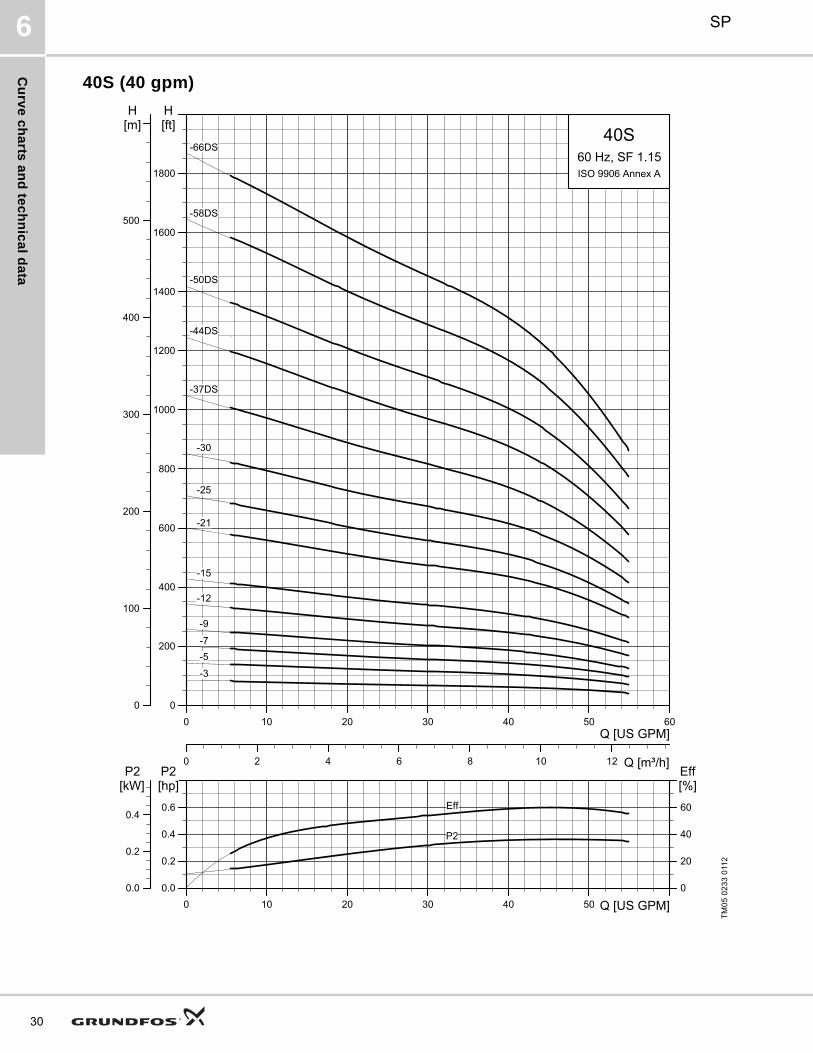
40S (40 gpm)
TM
05
02
33
011
2
0 10 20 30 40 50 Q [US GPM]0.0
0.2
0.4
0.6
[hp]P2
0
20
40
60
Eff[%]
0.0
0.2
0.4
[kW]P2
P2
Eff
0 10 20 30 40 50 60Q [US GPM]
0
200
400
600
800
1000
1200
1400
1600
1800
[ft]H
0
100
200
300
400
500
[m]H
0 2 4 6 8 10 12 Q [m³/h]
40S
ISO 9906 Annex A60 Hz, SF 1.15
-66DS
-58DS
-50DS
-44DS
-37DS
-30
-25
-21
-15
-12
-9
-7-5
-3

Cu
rve
ch
art
s a
nd
te
ch
nic
al
da
ta
SP 6
40S (40 gpm)
Notes:Control box is required for 3-wire, single-phase applications. Data does not include control box.DS designation = Built into sleeve, 2" NPT, 6" minimum well diameter.■ MS402 motor.● MS4000 motor.▲ MS6 motor.∧ MMS6000 motor.★ MMS8000 motor.♦ Takes MS6 motor; not available as complete.☼ Takes MMS6000 motor; not available as complete.* Takes MMS8000 motor; not available as complete.† Takes MMS10000 motor; not available as complete.
Pumpmodel
Nom. head[ft]
PhVolts
[V]Motor[Hp]
DimensionsNet
weight(complete)
[lb]
40S
A B C D E
TM
05
23
99
50
11
[in (mm)] [in (mm)] [in (mm)] [in (mm)] [in (mm)]
40S - Motor dia. 4 inch, 2 wire motor, 60 Hz, rated flow 40 gpm (2" NPT)
40S10-3 60 1 230 1 ■ 25.00 (635) 12.21 (310) 12.80 (325) 3.74 (95) 3.97 (101) 26.1
40S10-5 102 1 230 1.5 ■ 29.81 (757) 13.71 (348) 16.11 (409) 3.74 (95) 3.97 (101) 30.6
40S - Motor dia. 4 inch, 3 wire motor, 60 Hz, rated flow 40 gpm (2" NPT)
40S10-3 61 1 230 1 ■ 25.00 (635) 12.21 (310) 12.8 (325) 3.74 (95) 3.97 (101) 26.1
40S15-5 102
1 230 1.5 ■ 29.81 (757) 13.71 (348) 16.11 (409) 3.74 (95) 3.97 (101) 30.6
3230 1.5 ■ 28.31 (719) 12.21 (310) 16.11 (409) 3.74 (95) 3.97 (101) 30.6
460 1.5 ■ 28.31 (719) 12.21 (310) 16.11 (409) 3.74 (95) 3.97 (101) 30.6
40S20-7 143
1 230 2 ● 38.90 (988) 19.49 (495) 19.41 (493) 3.74 (95) 3.97 (101) 36.9
3230 2 ■ 33.12 (841) 13.71 (348) 19.41 (493) 3.74 (95) 3.97 (101) 36.9
460 2 ■ 33.12 (841) 13.71 (348) 19.41 (493) 3.74 (95) 3.97 (101) 36.9
40S30-9 184
1 230 3 ● 45.32 (1151) 22.60 (574) 22.72 (577) 3.74 (95) 3.97 (101) 74.1
3230 3 ● 40.71 (1034) 18.00 (457) 22.72 (577) 3.74 (95) 3.97 (101) 81.0
460 3 ● 40.71 (1034) 18.00 (457) 22.72 (577) 3.74 (95) 3.97 (101) 74.7E = Maximum diameter of pump including cable guard and motor.
40S50-12 245
1 230 5 ● 54.30 (1379) 26.62 (676) 27.68 (703) 3.74 (95) 3.97 (101) 81.0
3230 5 ● 50.40 (1280) 22.72 (577) 27.68 (703) 3.74 (95) 3.97 (101) 74.7
460 5 ● 50.40 (1280) 22.72 (577) 27.68 (703) 3.74 (95) 3.97 (101) 74.7
40S50-15 307
1 230 5 ● 59.26 (1505) 26.62 (676) 32.64 (829) 3.74 (95) 3.97 (101) 80.1
3230 5 ● 55.36 (1406) 22.72 (577) 32.64 (829) 3.74 (95) 3.97 (101) 80.1
460 5 ● 55.36 (1406) 22.72 (577) 32.64 (829) 3.74 (95) 3.97 (101) 80.1
40S - Motor dia. 6 inch, 3 wire motor, 60 Hz, rated flow 40 gpm (2" NPT)
40S75-21 429 3230 7.5 ● 69.22 (1758) 26.66 (677) 42.56 (1081) 3.74 (95) 3.97 (101) 113.3
460 7.5 ● 69.22 (1758) 26.66 (677) 42.56 (1081) 3.74 (95) 3.97 (101) 113.3
40S75-25 511 3230 7.5 ● 75.83 (1926) 26.66 (677) 49.18 (1249) 3.74 (95) 3.97 (101) 92.4
460 7.5 ● 75.83 (1926) 26.66 (677) 49.18 (1249) 3.74 (95) 3.97 (101) 92.4
40S100-30 613 3 460 10 ● 88.04 (2236) 30.60 (777) 57.45 (1459) 3.74 (95) 3.97 (101) 166.0
40S150-37DS 756 3230 15 ▲ 99.34 (2523) 27.88 (708) 71.46 (1815) 5.63 (143) 5.43 (138) 151.9
460 15 ▲ 99.34 (2523) 27.88 (708) 71.46 (1815) 5.63 (143) 5.43 (138) 151.9
40S150-44DS 899 3230 15 ▲ 110.91 (2817) 27.88 (708) 83.04 (2109) 5.63 (143) 5.43 (138) 165.1
460 15 ▲ 110.91 (2817) 27.88 (708) 83.04 (2109) 5.63 (143) 5.43 (138) 151.9
40S200-50DS 1022 3230 20 ▲ 136.23 (3460) 30.83 (783) 105.4 (2677) 5.63 (143) 5.51 (140) 226.9
460 20 ▲ 136.23 (3460) 30.83 (783) 105.4 (2677) 5.63 (143) 5.51 (140) 226.9
40S200-58DS 1186 3230 20 ▲ 149.45 (3796) 30.83 (783) 118.63 (3013) 5.63 (143) 5.51 (140) 251.1
460 20 ▲ 149.45 (3796) 30.83 (783) 118.63 (3013) 5.63 (143) 5.51 (140) 251.1
40S200-66DS 1349 3230 20 ▲ 162.68 (4132) 30.83 (783) 131.86 (3349) 5.63 (143) 5.51 (140) 266.5
460 20 ▲ 162.68 (4132) 30.83 (783) 131.86 (3349) 5.63 (143) 5.51 (140) 266.5
A
BC
E
D
NPT
31

Cu
rve
ch
arts
an
d te
ch
nic
al d
ata
SP6
32
60S (60 gpm)
TM
05
17
36
011
2
0 10 20 30 40 50 60 70 Q [US GPM]0.0
0.4
0.8
1.2
[hp]P2
0
20
40
60
Eff[%]
0.0
0.4
0.8
[kW]P2
Eff
P2
0 10 20 30 40 50 60 70 80 90Q [US GPM]
0
50
100
150
200
250
300
350
400
450
500
550
600
[ft]H
0
20
40
60
80
100
120
140
160
180
[m]H
0 2 4 6 8 10 12 14 16 18 Q [m³/h]
60S
ISO 9906 Annex A60 Hz, SF 1.15
-4
-5
-7
-9
-13
-18

Cu
rve
ch
art
s a
nd
te
ch
nic
al
da
ta
SP 6
60S (60 gpm)
Notes:Control box is required for 3-wire, single-phase applications. Data does not include control box.diameter.■ MS402 motor.● MS4000 motor.▲ MS6 motor.∧ MMS6000 motor.★ MMS8000 motor.♦ Takes MS6 motor; not available as complete.☼ Takes MMS6000 motor; not available as complete.* Takes MMS8000 motor; not available as complete.† Takes MMS10000 motor; not available as complete.
Pumpmodel
Nom. head[ft]
PhVolts
[V]Motor[Hp]
DimensionsNet
weight(complete)
[lb]
60S
A B C D E
TM
05
23
99
50
11
[in (mm)] [in (mm)] [in (mm)] [in (mm)] [in (mm)]
60S - Motor dia. 4 inch, 3 wire motor, 60 Hz, rated flow 60 gpm (2" NPT)
60S20-4 93
1 230 2 ● 37.01 (940) 19.49 (495) 17.52 (445) 3.74 (95) 3.97 (101) 36.0
3230 2 ■ 31.23 (793) 13.71 (348) 17.52 (445) 3.74 (95) 3.97 (101) 36.0
460 2 ■ 31.23 (793) 13.71 (348) 17.52 (445) 3.74 (95) 3.97 (101) 36.0
60S30-5 117
1 230 3 ● 42.68 (1084) 22.60 (574) 20.08 (510) 3.74 (95) 3.97 (101) 61.2
3230 3 ● 38.08 (967) 18.00 (457) 20.08 (510) 3.74 (95) 3.97 (101) 49.5
460 3 ● 38.08 (967) 18.00 (457) 20.08 (510) 3.74 (95) 3.97 (101) 58.5
60S50-7 164
1 230 5 ● 51.82 (1316) 26.62 (676) 25.20 (640) 3.74 (95) 3.97 (101) 81.0
3230 5 ● 47.92 (1217) 22.72 (577) 25.20 (640) 3.74 (95) 3.97 (101) 49.5
460 5 ● 47.92 (1217) 22.72 (577) 25.20 (640) 3.74 (95) 3.97 (101) 72.0
60S50-9 210
1 230 5 ● 56.93 (1446) 26.62 (676) 30.32 (770) 3.74 (95) 3.97 (101) 85.5
3230 5 ● 53.04 (1347) 22.72 (577) 30.32 (770) 3.74 (95) 3.97 (101) 76.5
460 5 ● 53.04 (1347) 22.72 (577) 30.32 (770) 3.74 (95) 3.97 (101) 76.5E = Maximum diameter of pump including cable guard and motor.
60S75-13 304 3230 7.5 ● 67.21 (1707) 26.66 (677) 40.56 (1030) 3.74 (95) 3.97 (101) 83.3
460 7.5 ● 67.21 (1707) 26.66 (677) 40.56 (1030) 3.74 (95) 3.97 (101) 136.8
60S100-18 420 3 460 10 ● 83.94 (2132) 30.60 (777) 53.35 (1355) 3.74 (95) 3.97 (101) 175.5
60S - Motor dia. 6 inch, 3 wire motor, 60 Hz, rated flow 60 gpm (2" NPT)
60S75-13 304 3230 7.5 ▲ 65.24 (1657) 22.25 (565) 43.00 (1092) 5.63 (143) 5.43 (138) 136.8
460 7.5 ▲ 65.24 (1657) 22.25 (565) 43.00 (1092) 5.63 (143) 5.43 (138) 136.8
60S100-18 420 3230 10 ▲ 79.02 (2007) 23.23 (590) 55.79 (1417) 5.63 (143) 5.43 (138) 207.0
460 10 ▲ 79.02 (2007) 23.23 (590) 55.79 (1417) 5.63 (143) 5.43 (138) 207.0
A
BC
E
D
NPT
33

Cu
rve
ch
arts
an
d te
ch
nic
al d
ata
SP6
34
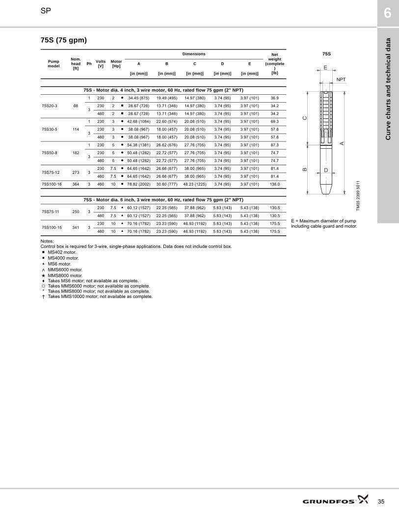
75S (75 gpm)
TM
05
02
34
011
2
0 10 20 30 40 50 60 70 80 Q [US GPM]0.0
0.4
0.8
1.2
[hp]P2
0
20
40
60
Eff[%]
0.0
0.4
0.8
[kW]P2
P2
Eff
0 10 20 30 40 50 60 70 80 90 100Q [US GPM]
0
50
100
150
200
250
300
350
400
450
500
[ft]H
0
20
40
60
80
100
120
140
160[m]H
0 2 4 6 8 10 12 14 16 18 20 Q [m³/h]
75S
ISO 9906 Annex A60 Hz, SF 1.15-16
-15
-12
-11
-8
-5
-3
Cu
rve
ch
art
s a
nd
te
ch
nic
al
da
ta
SP 6
75S (75 gpm)
Notes:Control box is required for 3-wire, single-phase applications. Data does not include control box.■ MS402 motor.● MS4000 motor.▲ MS6 motor.∧ MMS6000 motor.★ MMS8000 motor.♦ Takes MS6 motor; not available as complete.☼ Takes MMS6000 motor; not available as complete.* Takes MMS8000 motor; not available as complete.† Takes MMS10000 motor; not available as complete.
Pumpmodel
Nom. head[ft]
PhVolts
[V]Motor[Hp]
Dimensions Netweight
(complete)
[lb]
75S
A B C D E
TM
05
23
99
50
11
[in (mm)] [in (mm)] [in (mm)] [in (mm)] [in (mm)]
75S - Motor dia. 4 inch, 3 wire motor, 60 Hz, rated flow 75 gpm (2" NPT)
75S20-3 68
1 230 2 ● 34.45 (875) 19.49 (495) 14.97 (380) 3.74 (95) 3.97 (101) 36.9
3230 2 ■ 28.67 (728) 13.71 (348) 14.97 (380) 3.74 (95) 3.97 (101) 34.2
460 2 ■ 28.67 (728) 13.71 (348) 14.97 (380) 3.74 (95) 3.97 (101) 34.2
75S30-5 114
1 230 3 ● 42.68 (1084) 22.60 (574) 20.08 (510) 3.74 (95) 3.97 (101) 69.3
3230 3 ● 38.08 (967) 18.00 (457) 20.08 (510) 3.74 (95) 3.97 (101) 57.6
460 3 ● 38.08 (967) 18.00 (457) 20.08 (510) 3.74 (95) 3.97 (101) 57.6
75S50-8 182
1 230 5 ● 54.38 (1381) 26.62 (676) 27.76 (705) 3.74 (95) 3.97 (101) 87.3
3230 5 ● 50.48 (1282) 22.72 (577) 27.76 (705) 3.74 (95) 3.97 (101) 74.7
460 5 ● 50.48 (1282) 22.72 (577) 27.76 (705) 3.74 (95) 3.97 (101) 74.7
75S75-12 273 3230 7.5 ● 64.65 (1642) 26.66 (677) 38.00 (965) 3.74 (95) 3.97 (101) 81.4
460 7.5 ● 64.65 (1642) 26.66 (677) 38.00 (965) 3.74 (95) 3.97 (101) 81.4
75S100-16 364 3 460 10 ● 78.82 (2002) 30.60 (777) 48.23 (1225) 3.74 (95) 3.97 (101) 138.0
75S - Motor dia. 6 inch, 3 wire motor, 60 Hz, rated flow 75 gpm (2" NPT)
75S75-11 250 3230 7.5 ▲ 60.12 (1527) 22.25 (565) 37.88 (962) 5.63 (143) 5.43 (138) 130.5
460 7.5 ▲ 60.12 (1527) 22.25 (565) 37.88 (962) 5.63 (143) 5.43 (138) 130.5E = Maximum diameter of pump including cable guard and motor.75S100-15 341 3
230 10 ▲ 70.16 (1782) 23.23 (590) 46.93 (1192) 5.63 (143) 5.43 (138) 175.5
460 10 ▲ 70.16 (1782) 23.23 (590) 46.93 (1192) 5.63 (143) 5.43 (138) 175.5
A
BC
E
D
NPT
35

Cu
rve
ch
arts
an
d te
ch
nic
al d
ata
SP6
36
85S (85 gpm)
TM
05
02
35
011
20 20 40 60 80 100 120
Q [US GPM]
0
100
200
300
400
500
600
700
800
900
[ft]H
0 5 10 15 20 Q [m³/h]
0
50
100
150
200
250
[m]H
85S60 Hz, SF 1.15ISO 9906 Annex A
-18
-17
-16
-15
-14
-13
-12
-11
-10
-9
-8
-7
-6
-5
-4
-3
-2
-1
0 20 40 60 80 100 Q [US GPM]0
10
20
30
40[ft]H
0
20
40
60
80[%]Eff
0
4
8
12
[m]H
NPSH
Eff

Cu
rve
ch
art
s a
nd
te
ch
nic
al
da
ta
SP 6
85S (85 gpm)
TM
05
02
36
011
20 20 40 60 80 100 120
Q [US GPM]
400
600
800
1000
1200
1400
1600
1800
2000
2200
[ft]H
0 5 10 15 20 Q [m³/h]
200
300
400
500
600
700
[m]H
85S60 Hz, SF 1.15ISO 9906 Annex A
-39
-36
-33
-30-29-28-27
-26-25-24-23-22-21-20-19
0 20 40 60 80 100 Q [US GPM]0
10
20
30
40[ft]H
0
20
40
60
80[%]Eff
0
4
8
12
[m]H
NPSH
Eff
37

Cu
rve
ch
arts
an
d te
ch
nic
al d
ata
SP6
38
85S (85 gpm) pump power requirement (P2)
TM
05
02
37
011
2
0 20 40 60 80 100 120Q [US GPM]
0
2
4
6
8
10
12
14
16
18
20
22
24
26
[hp]P2
0 5 10 15 20 Q [m³/h]
0
2
4
6
8
10
12
14
16
18
[kW]P2
85S60 Hz, SF 1.15ISO 9906 Annex A
-18
-17
-16
-15
-14
-13
-12
-11
-10
-9
-8
-7
-6
-5
-4
-3
-2
-1

Cu
rve
ch
art
s a
nd
te
ch
nic
al
da
ta
SP 6
85S (85 gpm) pump power requirement (P2)
TM
05
02
38
011
2
0 20 40 60 80 100 120Q [US GPM]
10
12
16
20
24
28
32
36
40
44
48
52
56
[hp]P2
0 5 10 15 20 Q [m³/h]
8
12
16
20
24
28
32
36
40
[kW]P2
85S60 Hz, SF 1.15ISO 9906 Annex A
-39
-36
-33
-30
-29
-28
-27
-26
-25-24-23
-22
-21
-20
-19
39
Cu
rve
ch
arts
an
d te
ch
nic
al d
ata
SP6
40
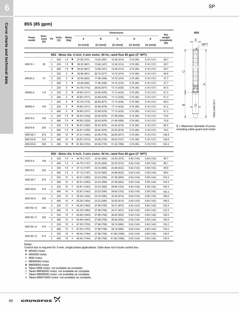
85S (85 gpm)
Notes:Control box is required for 3-wire, single-phase applications. Data does not include control box.■ MS402 motor.● MS4000 motor.▲ MS6 motor.∧ MMS6000 motor.★ MMS8000 motor.♦ Takes MS6 motor; not available as complete.☼ Takes MMS6000 motor; not available as complete.* Takes MMS8000 motor; not available as complete.† Takes MMS10000 motor; not available as complete.
Pumpmodel
Nom. head[ft]
PhVolts
[V]Motor[Hp]
DimensionsNet
weight(complete)
[lb]
85S
A B C D E
TM
05
24
00
50
11
[in (mm)] [in (mm)] [in (mm)] [in (mm)] [in (mm)]
85S - Motor dia. 4 inch, 3 wire motor, 60 Hz, rated flow 85 gpm (3" NPT)
85S15-1 35
1 230 1.5 ■ 27.60 (701) 15.24 (387) 12.36 (314) 3.74 (95) 5.16 (131) 29.7
3 230 1.5 ■ 26.02 (661) 13.66 (347) 12.36 (314) 3.74 (95) 5.16 (131) 29.7
3 460 1.5 ■ 26.02 (661) 13.66 (347) 12.36 (314) 3.74 (95) 5.16 (131) 29.7
85S30-2 74
1 230 3 ● 32.69 (951) 22.72 (577) 14.72 (374) 3.74 (95) 5.16 (131) 55.8
3 230 3 ● 32.69 (830) 17.96 (456) 14.72 (374) 3.74 (95) 5.16 (131) 47.7
3 460 3 ● 32.69 (830) 17.96 (456) 14.72 (374) 3.74 (95) 5.16 (131) 47.7
85S50-3 114
1 230 5 ● 43.78 (1112) 26.65 (677) 17.13 (435) 3.74 (95) 5.16 (131) 67.5
3 230 5 ● 39.80 (1011) 22.69 (576) 17.13 (435) 3.74 (95) 5.16 (131) 51.3
3 460 5 ● 39.80 (1011) 22.69 (576) 17.13 (435) 3.74 (95) 5.16 (131) 51.3
85S50-4 154
1 230 5 ● 43.78 (1112) 26.65 (677) 17.13 (435) 3.74 (95) 5.16 (131) 69.3
3 230 5 ● 39.80 (1011) 22.69 (576) 17.13 (435) 3.74 (95) 5.16 (131) 61.2
3 460 5 ● 39.80 (1011) 22.69 (576) 17.13 (435) 3.74 (95) 5.16 (131) 61.2
85S75-5 1943 230 7.5 ● 48.50 (1232) 26.62 (676) 21.89 (556) 3.74 (95) 5.16 (131) 73.8
3 460 7.5 ● 48.50 (1232) 26.62 (676) 21.89 (556) 3.74 (95) 5.16 (131) 73.8
85S75-6 2343 230 7.5 ● 50.87 (1292) 26.62 (676) 24.25 (616) 3.74 (95) 5.16 (131) 85.5 E = Maximum diameter of pump
including cable guard and motor.3 460 7.5 ● 50.87 (1292) 26.62 (676) 24.25 (616) 3.74 (95) 5.16 (131) 76.5
85S100-7 274 3 460 10 ● 57.21 (1453) 30.56 (776) 26.65 (677) 3.74 (95) 5.16 (131) 136.8
85S100-8 314 3 460 10 ● 59.57 (1513) 30.56 (776) 29.02 (737) 3.74 (95) 5.16 (131) 138.6
85S100-9 353 3 460 10 ● 61.98 (1574) 30.56 (776) 31.42 (798) 3.74 (95) 5.16 (131) 140.4
85S - Motor dia. 6 inch, 3 wire motor, 60 Hz, rated flow 85 gpm (3" NPT)
85S75-5 1943 230 7.5 ▲ 44.76 (1137) 22.52 (565) 22.52 (572) 5.63 (143) 5.59 (142) 98.1
3 460 7.5 ▲ 44.76 (1137) 22.52 (565) 22.52 (572) 5.63 (143) 5.59 (142) 98.1
85S75-6 2343 230 7.5 ▲ 47.12 (1197) 22.24 (565) 24.88 (632) 5.63 (143) 5.59 (142) 99.9
3 460 7.5 ▲ 47.12 (1197) 22.24 (565) 24.88 (632) 5.63 (143) 5.59 (142) 99.9
85S100-7 2743 230 10 ▲ 50.51 (1283) 23.23 (590) 27.28 (693) 5.63 (143) 5.59 (142) 103.5
3 460 10 ▲ 50.51 (1283) 23.23 (590) 27.28 (693) 5.63 (143) 5.59 (142) 103.5
85S100-8 3143 230 10 ▲ 52.87 (1343) 23.23 (590) 29.65 (753) 5.63 (143) 5.59 (142) 105.3
3 460 10 ▲ 52.87 (1343) 23.23 (590) 29.65 (753) 5.63 (143) 5.59 (142) 105.3
85S100-9 3533 230 10 ▲ 55.28 (1404) 23.23 (590) 32.05 (814) 5.63 (143) 5.60 (142) 108.0
3 460 10 ▲ 55.28 (1404) 23.23 (590) 32.05 (814) 5.63 (143) 5.60 (142) 108.0
85S150-10 3933 230 15 ▲ 62.29 (1582) 27.88 (708) 34.41 (874) 5.63 (143) 5.60 (142) 122.4
3 460 15 ▲ 62.29 (1582) 27.88 (708) 34.41 (874) 5.63 (143) 5.60 (142) 122.4
85S150-11 4333 230 15 ▲ 64.69 (1643) 27.88 (708) 36.82 (935) 5.63 (143) 5.60 (142) 126.0
3 460 15 ▲ 64.69 (1643) 27.88 (708) 36.82 (935) 5.63 (143) 5.60 (142) 126.0
85S150-12 4733 230 15 ▲ 67.05 (1703) 27.88 (708) 39.18 (995) 5.63 (143) 5.60 (142) 133.2
3 460 15 ▲ 67.05 (1703) 27.88 (708) 39.18 (995) 5.63 (143) 5.60 (142) 133.2
85S150-13 5133 230 15 ▲ 69.45 (1764) 27.88 (708) 41.58 (1056) 5.63 (143) 5.60 (142) 135.0
3 460 15 ▲ 69.45 (1764) 27.88 (708) 41.58 (1056) 5.63 (143) 5.60 (142) 135.0
NPT
A
BC
D
E

Cu
rve
ch
art
s a
nd
te
ch
nic
al
da
ta
SP 6
85S (85 gpm)
Notes:Control box is required for 3-wire, single-phase applications. Data does not include control box.DS designation = Built into sleeve, 3" NPT, 8" minimum well diameter.■ MS402 motor.● MS4000 motor.▲ MS6 motor.∧ MMS6000 motor.★ MMS8000 motor.♦ Takes MS6 motor; not available as complete.☼ Takes MMS6000 motor; not available as complete.* Takes MMS8000 motor; not available as complete.† Takes MMS10000 motor; not available as complete.
Pumpmodel
Nom. head[ft]
PhVolts
[V]Motor[Hp]
DimensionsNet
weight(complete)
[lb]
85S
A B C D E
TM
05
24
00
50
11
[in (mm)] [in (mm)] [in (mm)] [in (mm)] [in (mm)]
85S - Motor dia. 6 inch, 3 wire motor, 60 Hz, rated flow 85 gpm (3" NPT)
85S200-14 5333 230 20 ▲ 74.77 (1899) 30.83 (783) 43.94 (1116) 5.63 (143) 5.60 (142) 143.1
3 460 20 ▲ 74.77 (1899) 30.83 (783) 43.94 (1116) 5.63 (143) 5.60 (142) 143.1
85S200-15 5933 230 20 ▲ 77.17 (1960) 30.83 (783) 46.34 (1177) 5.63 (143) 5.60 (142) 147.6
3 460 20 ▲ 77.17 (1960) 30.83 (783) 46.34 (1177) 5.63 (143) 5.60 (142) 147.6
85S200-16 6333 230 20 ▲ 79.53 (2020) 30.83 (783) 48.71 (1237) 5.63 (143) 5.60 (142) 157.5
3 460 20 ▲ 79.53 (2020) 30.83 (783) 48.71 (1237) 5.63 (143) 5.60 (142) 157.5
85S200-17 6723 230 20 ▲ 81.93 (2081) 30.83 (783) 51.11 (1298) 5.63 (143) 5.60 (142) 160.2
3 460 20 ▲ 81.93 (2081) 30.83 (783) 51.11 (1298) 5.63 (143) 5.60 (142) 160.2
85S200-18 7123 230 20 ▲ 84.30 (2141) 30.83 (783) 53.47 (1358) 5.63 (143) 5.60 (142) 161.1
3 460 20 ▲ 84.30 (2141) 30.83 (783) 53.47 (1358) 5.63 (143) 5.60 (142) 179.0
85S250-19 7523 230 25 ▲ 88.86 (2257) 33.00 (838) 55.87 (1419) 5.63 (143) 5.60 (142) 191.7
3 460 25 ▲ 88.86 (2257) 33.00 (838) 55.87 (1419) 5.63 (143) 5.60 (142) 191.7
85S250-20 7923 230 25 ▲ 91.86 (2333) 33.00 (838) 58.86 (1495) 5.63 (143) 5.60 (142) 195.3
3 460 25 ▲ 91.86 (2333) 33.00 (838) 58.86 (1495) 5.63 (143) 5.60 (142) 195.3
85S250-21 8323 230 25 ▲ 94.26 (2394) 33.00 (838) 61.26 (1556) 5.63 (143) 5.60 (142) 198.0 E = Maximum diameter of pump
including cable guard and motor.3 460 25 ▲ 94.26 (2394) 33.00 (838) 61.26 (1556) 5.63 (143) 5.60 (142) 198.0
85S250-22 8723 230 25 ▲ 96.62 (2454) 33.00 (838) 63.63 (1616) 5.63 (143) 5.60 (142) 199.8
3 460 25 ▲ 96.62 (2454) 33.00 (838) 63.63 (1616) 5.63 (143) 5.60 (142) 199.8
85S300-23 9123 230 30 ▲ 101.54 (2579) 35.56 (903) 65.99 (1676) 5.63 (143) 5.60 (142) 199.8
3 460 30 ▲ 101.54 (2579) 35.56 (903) 65.99 (1676) 5.63 (143) 5.60 (142) 199.8
85S300-24 9523 230 30 ▲ 103.94 (2640) 35.56 (903) 68.39 (1737) 5.63 (143) 5.60 (142) 216.0
3 460 30 ▲ 103.94 (2640) 35.56 (903) 68.39 (1737) 5.63 (143) 5.60 (142) 216.0
85S300-25 9913 230 30 ▲ 106.34 (2701) 35.56 (903) 70.79 (1798) 5.63 (143) 5.60 (142) 219.6
3 460 30 ▲ 106.34 (2701) 35.56 (903) 70.79 (1798) 5.63 (143) 5.60 (142) 219.6
85S300-26 10313 230 30 ▲ 108.71 (2761) 35.56 (903) 73.15 (1858) 5.63 (143) 5.60 (142) 221.4
3 460 30 ▲ 108.71 (2761) 35.56 (903) 73.15 (1858) 5.63 (143) 5.60 (142) 221.4
85S300-27 10713 230 30 ▲ 111.11 (2822) 35.56 (903) 75.56 (1919) 5.63 (143) 5.60 (142) 234.9
3 460 30 ▲ 111.11 (2822) 35.56 (903) 75.56 (1919) 5.63 (143) 5.60 (142) 234.9
85S400-28 1111 3 460 40 ▲ 118.19 (3002) 40.28 (1023) 77.92 (1979) 5.63 (143) 5.60 (142) 246.6
85S400-29 1151 3 460 40 ▲ 120.6 (3063) 40.28 (1023) 80.32 (2040) 5.63 (143) 5.60 (142) 248.4
85S400-30 1191 3 460 40 ▲ 122.96 (3123) 40.28 (1023) 82.68 (2100) 5.63 (143) 5.60 (142) 270.0
85S400-33DS 1310 3 460 40 ▲ 139.22 (3536) 40.28 (1023) 98.94 (2513) 5.63 (143) 6.90 (176) 515.5
85S400-36DS 1430 3 460 40 ▲ 146.34 (3717) 40.28 (1023) 106.07 (2694) 5.63 (143) 6.90 (176) 454.8
85S500-39DS 1510 3 460 50 ▲ 169.26 (4299) 56.03 (1423) 113.23 (2876) 5.63 (143) 6.90 (176) 469.0
85S - Motor dia. 8 inch, 3 wire motor, 60 Hz, rated flow 85 gpm (3" NPT)
85S400-33DS 1310 3 460 40 ★ 140.87 (3578) 43.71 (1110) 97.17 (2468) 7.56 (192) 7.56 (192) 652.7
85S400-36DS 1310 3 460 40 ★ 147.96 (3758) 43.71 (1110) 104.26 (2648) 7.56 (192) 7.56 (192) 592.0
85S400-39DS 1510 3 460 50 ★ 155.04 (3938) 43.71 (1110) 111.34 (2828) 7.56 (192) 7.56 (192) 537.2
NPT
A
BC
D
E
41

Cu
rve
ch
arts
an
d te
ch
nic
al d
ata
SP6
42
150S (150 gpm)
TM
05
02
39
011
2
0 20 40 60 80 100 120 140 160 180 200 220Q [US GPM]
0
50
100
150
200
250
300
350
400
450
500
550
600
650
700
750
800
850
900
950
[ft]H
0 5 10 15 20 25 30 35 40 Q [m³/h]
0
20
40
60
80
100
120
140
160
180
200
220
240
260
280
[m]H
150S60 Hz, SF 1.15ISO 9906 Annex A
-17
-16
-15
-14
-13
-12
-11
-10
-9
-8
-7
-6
-5
-4
-3
-2
-1
0 20 40 60 80 100 120 140 160 180 Q [US GPM]0
10
20
30
40[ft]H
0
20
40
60
80[%]Eff
0
4
8
12
[m]H
NPSH
Eff

Cu
rve
ch
art
s a
nd
te
ch
nic
al
da
ta
SP 6
150S (150 gpm)
TM
05
02
40
011
20 20 40 60 80 100 120 140 160 180 200 220
Q [US GPM]
200
400
600
800
1000
1200
1400
1600
1800
2000
2200
[ft]H
0 5 10 15 20 25 30 35 40 Q [m³/h]
100
200
300
400
500
600
700[m]H
150S60 Hz, SF 1.15ISO 9906 Annex A-39
-36
-33
-31
-29
-28-27-26-25-24-23-22-21-20-19-18
0 20 40 60 80 100 120 140 160 180 Q [US GPM]0
10
20
30
40[ft]H
0
20
40
60
80[%]Eff
0
4
8
12[m]H
NPSH
Eff
43

Cu
rve
ch
arts
an
d te
ch
nic
al d
ata
SP6
44
150S (150 gpm) pump power requirement (P2)
TM
05
02
41
011
2
0 20 40 60 80 100 120 140 160 180 200 220Q [US GPM]
0
2
4
6
8
10
12
14
16
18
20
22
24
26
28
30
32
34
36
38
[hp]P2
0 5 10 15 20 25 30 35 40 Q [m³/h]
0
2
4
6
8
10
12
14
16
18
20
22
24
26
28
[kW]P2
150S60 Hz, SF 1.15ISO 9906 Annex A
-17
-16
-15
-14
-13
-12
-11
-10
-9
-8
-7
-6
-5
-4
-3
-2
-1

Cu
rve
ch
art
s a
nd
te
ch
nic
al
da
ta
SP 6
150S (150 gpm) pump power requirement (P2)
TM
05
02
42
011
20 20 40 60 80 100 120 140 160 180 200 220Q [US GPM]
20
25
30
35
40
45
50
55
60
65
70
75
80
85
[hp]P2
0 5 10 15 20 25 30 35 40 Q [m³/h]
15
20
25
30
35
40
45
50
55
60
[kW]P2
150S60 Hz, SF 1.15ISO 9906 Annex A
-39
-36
-33
-31
-29
-28
-27
-26
-25
-24
-23
-22
-21
-20
-19
-18
45

Cu
rve
ch
arts
an
d te
ch
nic
al d
ata
SP6
46
150S (150 gpm)
Notes:Control box is required for 3-wire, single-phase applications. Data does not include control box.■ MS402 motor.● MS4000 motor.▲ MS6 motor.∧ MMS6000 motor.★ MMS8000 motor.♦ Takes MS6 motor; not available as complete.☼ Takes MMS6000 motor; not available as complete.* Takes MMS8000 motor; not available as complete.† Takes MMS10000 motor; not available as complete.
Pumpmodel
Nom. head[ft]
PhVolts
[V]Motor[Hp]
DimensionsNet
weight(complete)
[lb]
150S
A B C D E
TM
05
111
2 2
111
[in (mm)] [in (mm)] [in (mm)] [in (mm)] [in (mm)]
150S - Motor dia. 4 inch, 3 wire motor, 60 Hz, rated flow 150 gpm (3" NPT)
150S20-1 33
1 230 2 ● 33.30 (846) 19.57 (497) 13.75 (349) 3.75 (95) 5.16 (131) 49.5
3 230 2 ■ 28.98 (736) 15.23 (387) 13.75 (349) 3.75 (95) 5.16 (131) 45.0
3 460 2 ■ 28.98 (736) 15.23 (387) 13.75 (349) 3.75 (95) 5.16 (131) 45.0
150S50-2 71
1 230 5 ● 44.17 (1122) 26.65 (677) 17.52 (445) 3.75 (95) 5.16 (131) 67.5
3 230 5 ● 40.20 (1021) 22.69 (576) 17.52 (445) 3.75 (95) 5.16 (131) 42.3
3 460 5 ● 40.20 (1021) 22.69 (576) 17.52 (445) 3.75 (95) 5.16 (131) 42.3
150S75-3 1083 230 7.5 ● 47.91 (1217) 26.63 (676) 21.3 (541) 3.75 (95) 5.16 (131) 51.3
3 460 7.5 ● 47.91 (1217) 26.63 (676) 21.3 (541) 3.75 (95) 5.16 (131) 82.8
150S75-4 1463 230 7.5 ● 51.71 (1313) 26.63 (676) 25.08 (637) 3.75 (95) 5.16 (131) 85.5
3 460 7.5 ● 51.71 (1313) 26.63 (676) 25.08 (637) 3.75 (95) 5.16 (131) 85.5
150S100-5 184 3 460 10 ● 59.42 (1509) 30.56 (776) 28.86 (733) 3.75 (95) 5.16 (131) 135.9
150S - Motor dia. 6 inch, 3 wire motor, 60 Hz, rated flow 150 gpm (3" NPT)
150S75-4 1463 230 7.5 ▲ 47.96 (1218) 22.25 (565) 25.71 (653) 5.63 (143) 5.60 (142) 99.9
3 460 7.5 ▲ 47.96 (1218) 22.25 (565) 25.71 (653) 5.63 (143) 5.60 (142) 99.9 E = Maximum diameter of pump including cable guard and motor.
150S100-5 1843 230 10 ▲ 52.72 (1339) 23.23 (590) 29.49 (749) 5.63 (143) 5.60 (142) 73.8
3 460 10 ▲ 52.72 (1339) 23.23 (590) 29.49 (749) 5.63 (143) 5.60 (142) 73.8
150S150-6 2223 230 15 ▲ 61.15 (1553) 27.88 (708) 33.27 (845) 5.63 (143) 5.60 (142) 119.7
3 460 15 ▲ 61.15 (1553) 27.88 (708) 33.27 (845) 5.63 (143) 5.60 (142) 119.7
150S150-7 2603 230 15 ▲ 64.93 (1649) 27.88 (708) 37.05 (941) 5.63 (143) 5.60 (142) 127.8
3 460 15 ▲ 64.93 (1649) 27.88 (708) 37.05 (941) 5.63 (143) 5.60 (142) 127.8
150S150-8 2973 230 15 ▲ 68.71 (1745) 27.88 (708) 40.83 (1037) 5.63 (143) 5.60 (142) 137.7
3 460 15 ▲ 68.71 (1745) 27.88 (708) 40.83 (1037) 5.63 (143) 5.60 (142) 137.7
150S200-9 3353 230 20 ▲ 75.44 (1916) 30.83 (783) 44.61 (1133) 5.63 (143) 5.60 (142) 141.3
3 460 20 ▲ 75.44 (1916) 30.83 (783) 44.61 (1133) 5.63 (143) 5.60 (142) 141.3
150S200-10 3733 230 20 ▲ 79.22 (2012) 30.83 (783) 48.39 (1229) 5.63 (143) 5.60 (142) 151.2
3 460 20 ▲ 79.22 (2012) 30.83 (783) 48.39 (1229) 5.63 (143) 5.60 (142) 151.2
150S200-11 4113 230 20 ▲ 83.00 (2108) 30.83 (783) 52.17 (1325) 5.63 (143) 5.60 (142) 166.5
3 460 20 ▲ 83.00 (2108) 30.83 (783) 52.17 (1325) 5.63 (143) 5.60 (142) 166.5
150S250-12 4483 230 25 ▲ 88.86 (2257) 32.92 (836) 55.95 (1421) 5.63 (143) 5.60 (142) 188.1
3 460 25 ▲ 88.86 (2257) 32.92 (836) 55.95 (1421) 5.63 (143) 5.60 (142) 188.1
150S250-13 4863 230 25 ▲ 92.64 (2353) 32.92 (836) 59.73 (1517) 5.63 (143) 5.60 (142) 201.6
3 460 25 ▲ 92.64 (2353) 32.92 (836) 59.73 (1517) 5.63 (143) 5.60 (142) 201.6
150S250-14 5243 230 25 ▲ 96.42 (2449) 32.92 (836) 63.51 (1613) 5.63 (143) 5.60 (142) 206.1
3 460 25 ▲ 96.42 (2449) 32.92 (836) 63.51 (1613) 5.63 (143) 5.60 (142) 206.1
A
BC
E
D
NPT

Cu
rve
ch
art
s a
nd
te
ch
nic
al
da
ta
SP 6
150S (150 gpm)
Notes:Control box is required for 3-wire, single-phase applications. Data does not include control box.DS designation = Built into sleeve, 3" NPT, 8" minimum well diameter.■ MS402 motor.● MS4000 motor.▲ MS6 motor.∧ MMS6000 motor.★ MMS8000 motor.♦ Takes MS6 motor; not available as complete.☼ Takes MMS6000 motor; not available as complete.* Takes MMS8000 motor; not available as complete.† Takes MMS10000 motor; not available as complete.
Pumpmodel
Nom. head[ft]
PhVolts
[V]Motor[Hp]
DimensionsNet
weight(complete)
[lb]
150S
A B C D E
TM
05
111
2 2
111
[in (mm)] [in (mm)] [in (mm)] [in (mm)] [in (mm)]
150S - Motor dia. 6 inch, 3 wire motor, 60 Hz, rated flow 150 gpm (3" NPT)
150S300-15 5623 230 30 ▲ 102.84 (2612) 35.56 (903) 67.29 (1709) 5.63 (143) 5.60 (142) 209.7
3 460 30 ▲ 102.84 (2612) 35.56 (903) 67.29 (1709) 5.63 (143) 5.60 (142) 209.7
150S300-16 6003 230 30 ▲ 106.62 (2708) 35.56 (903) 71.07 (1805) 5.63 (143) 5.60 (142) 211.5
3 460 30 ▲ 106.62 (2708) 35.56 (903) 71.07 (1805) 5.63 (143) 5.60 (142) 211.5
150S300-17 6373 230 30 ▲ 110.4 (2804) 35.56 (903) 74.85 (1901) 5.63 (143) 5.60 (142) 216.0
3 460 30 ▲ 110.4 (2804) 35.56 (903) 74.85 (1901) 5.63 (143) 5.60 (142) 246.6
150S400-18 675 3 460 40 ▲ 118.9 (3020) 40.28 (1023) 78.63 (1997) 5.63 (143) 5.60 (142) 246.6
150S400-19 713 3 460 40 ▲ 122.68 (3116) 40.28 (1023) 82.41 (2093) 5.63 (143) 5.60 (142) 248.4
150S400-20 751 3 460 40 ▲ 126.46 (3212) 40.28 (1023) 86.19 (2189) 5.63 (143) 5.60 (142) 291.0
150S400-21 789 3 460 40 ▲ 130.24 (3308) 40.28 (1023) 89.97 (2285) 5.63 (143) 5.67 (144) 271.8
150S400-22 826 3 460 40 ▲ 134.02 (3404) 40.28 (1023) 93.75 (2381) 5.63 (143) 5.67 (144) 305.9
150S400-23 864 3 460 40 ▲ 137.8 (3500) 40.28 (1023) 97.52 (2477) 5.63 (143) 5.67 (144) 277.2
150S500-24 902 3 460 50 ☼ 157.41 (3998) 56.11 (1425) 101.3 (2573) 5.67 (144) 5.60 (142) 411.8
150S500-25 940 3 460 50 ☼ 161.19 (4094) 56.11 (1425) 105.08 (2669) 5.67 (144) 5.60 (142) 419.0
150S500-26 977 3 460 50 ☼ 164.97 (4190) 56.11 (1425) 108.86 (2765) 5.67 (144) 5.60 (142) 426.2 E = Maximum diameter of pump including cable guard and motor.150S500-27 1015 3 460 50 ☼ 168.75 (4286) 56.11 (1425) 112.64 (2861) 5.67 (144) 5.60 (142) 433.4
150S500-28 1053 3 460 50 ☼ 172.52 (4382) 56.11 (1425) 116.42 (2957) 5.67 (144) 5.60 (142) 440.6
150S600-29DS 1091 3 460 60 - — — 129.05 (3278) — 7.10 (181) —
150S600-31DS 1166 3 460 60 - — — 136.61 (3470) — 7.10 (181) —
150S600-33DS 1242 3 460 60 - — — 144.17 (3662) — 7.10 (181) —
150S - Motor dia. 8 inch, 3 wire motor, 60 Hz, rated flow 150 gpm (3" NPT)
150S500-24 902 3 460 50 * 148.12 (3762) 45.67 (1160) 102.45 (2602) 7.56 (192) 7.56 (192) 484.5
150S500-25 940 3 460 50 * 151.89 (3858) 45.67 (1160) 106.23 (2698) 7.56 (192) 7.56 (192) 491.7
150S500-26 977 3 460 50 * 155.67 (3954) 45.67 (1160) 110.00 (2794) 7.56 (192) 7.56 (192) 498.9
150S500-27 1015 3 460 50 * 159.45 (4050) 45.67 (1160) 113.78 (2890) 7.56 (192) 7.56 (192) 506.1
150S500-28 1053 3 460 50 * 163.23 (4146) 45.67 (1160) 117.56 (2986) 7.56 (192) 7.56 (192) 513.3
150S600-29DS 1091 3 460 60 * 177.92 (4519) 50.00 (1270) 127.92 (3249) 7.56 (192) 7.56 (192) 612.7
150S600-31DS 1166 3 460 60 * 185.48 (4711) 50.00 (1270) 135.48 (3441) 7.56 (192) 7.56 (192) 623.7
150S600-33DS 1242 3 460 60 * 193.04 (4903) 50.00 (1270) 143.04 (3633) 7.56 (192) 7.56 (192) 639.1
150S750-36DS 1355 3 460 75 * 207.52 (5271) 53.15 (1350) 154.38 (3921) 7.56 (192) 7.56 (192) 689.2
150S750-39DS 1469 3 460 75 * 218.86 (5559) 53.15 (1350) 165.71 (4209) 7.56 (192) 7.56 (192) 704.6A
BC
E
D
NPT
47

Cu
rve
ch
arts
an
d te
ch
nic
al d
ata
SP6
48
230S (230 gpm)
TM
05
02
43
03
12
0 50 100 150 200 250 300 350Q [US GPM]
0
50
100
150
200
250
300
350
400
450
500
[ft]H
0 10 20 30 40 50 60 70 Q [m³/h]
0
20
40
60
80
100
120
140
160[m]H
230S60 Hz, SF 1.15ISO 9906 Annex A-8-B
-8
-7
-7-C
-6
-5
-5-B
-4
-4-BC
-3
-3-BB
-2
-2-AB
-1
-1-A-1-B
0 50 100 150 200 250 Q [US GPM]0
10
20
30
40[ft]H
0
20
40
60
80[%]Eff
0
4
8
12
[m]H
NPSH
Eff
TM05
0243
0811

Cu
rve
ch
art
s a
nd
te
ch
nic
al
da
ta
SP 6
230S (230 gpm)
TM
05
02
44
03
120 50 100 150 200 250 300 350
Q [US GPM]
100
200
300
400
500
600
700
800
900
1000
1100
1200
1300
1400
1500
[ft]H
0 10 20 30 40 50 60 70 Q [m³/h]
50
100
150
200
250
300
350
400
450
[m]H
230S60 Hz, SF 1.15ISO 9906 Annex A
-9-BB
-22
-20
-19
-18
-17
-16
-15
-14
-13
-12
-11
-10
-9
0 50 100 150 200 250 300Q [US GPM]0
10
20
30
40[ft]H
0
20
40
60
80[%]Eff
0
4
8
12
[m]H
NPSH
Eff
49

Cu
rve
ch
arts
an
d te
ch
nic
al d
ata
SP6
50
230S (230 gpm) pump power requirement (P2)
TM
05
02
45
011
20 50 100 150 200 250 300 350Q [US GPM]
0
2
4
6
8
10
12
14
16
18
20
22
24
26
28
30
[hp]P2
0 10 20 30 40 50 60 70 Q [m³/h]
0
2
4
6
8
10
12
14
16
18
20
22
[kW]P2
230S60 Hz, SF 1.15ISO 9906 Annex A
-8
-7
-7-C
-6
-5
-5-B
-4
-4-BC-3
-3-BB-2
-2-AB
-1
-1-A-1-B

Cu
rve
ch
art
s a
nd
te
ch
nic
al
da
ta
SP 6
230S (230 gpm) pump power requirement (P2)
TM
05
02
46
011
2
0 50 100 150 200 250 300 350Q [US GPM]
20
25
30
35
40
45
50
55
60
65
70
75
80
85
[hp]P2
0 10 20 30 40 50 60 70 Q [m³/h]
15
20
25
30
35
40
45
50
55
60
[kW]P2
230S60 Hz, SF 1.15ISO 9906 Annex A
-22
-20
-19
-18
-17
-16
-15
-14
-13
-12
-11
-10
-9
51
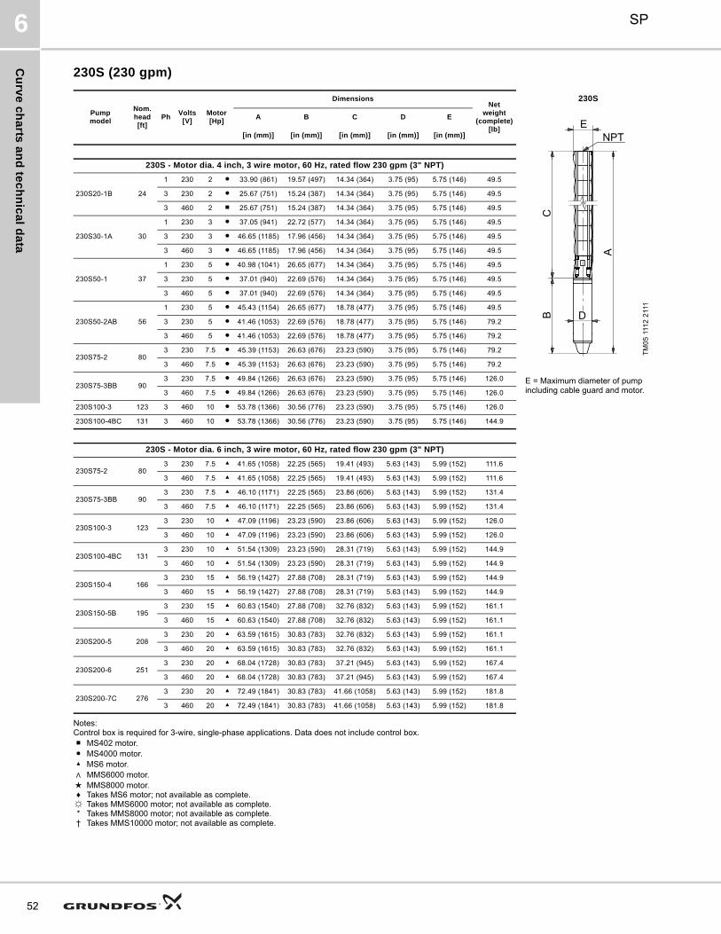
Cu
rve
ch
arts
an
d te
ch
nic
al d
ata
SP6
52
230S (230 gpm)
Notes:Control box is required for 3-wire, single-phase applications. Data does not include control box.■ MS402 motor.● MS4000 motor.▲ MS6 motor.∧ MMS6000 motor.★ MMS8000 motor.♦ Takes MS6 motor; not available as complete.☼ Takes MMS6000 motor; not available as complete.* Takes MMS8000 motor; not available as complete.† Takes MMS10000 motor; not available as complete.
Pumpmodel
Nom. head[ft]
PhVolts
[V]Motor[Hp]
DimensionsNet
weight(complete)
[lb]
230S
A B C D E
TM
05
111
2 2
111
[in (mm)] [in (mm)] [in (mm)] [in (mm)] [in (mm)]
230S - Motor dia. 4 inch, 3 wire motor, 60 Hz, rated flow 230 gpm (3" NPT)
230S20-1B 24
1 230 2 ● 33.90 (861) 19.57 (497) 14.34 (364) 3.75 (95) 5.75 (146) 49.5
3 230 2 ● 25.67 (751) 15.24 (387) 14.34 (364) 3.75 (95) 5.75 (146) 49.5
3 460 2 ■ 25.67 (751) 15.24 (387) 14.34 (364) 3.75 (95) 5.75 (146) 49.5
230S30-1A 30
1 230 3 ● 37.05 (941) 22.72 (577) 14.34 (364) 3.75 (95) 5.75 (146) 49.5
3 230 3 ● 46.65 (1185) 17.96 (456) 14.34 (364) 3.75 (95) 5.75 (146) 49.5
3 460 3 ● 46.65 (1185) 17.96 (456) 14.34 (364) 3.75 (95) 5.75 (146) 49.5
230S50-1 37
1 230 5 ● 40.98 (1041) 26.65 (677) 14.34 (364) 3.75 (95) 5.75 (146) 49.5
3 230 5 ● 37.01 (940) 22.69 (576) 14.34 (364) 3.75 (95) 5.75 (146) 49.5
3 460 5 ● 37.01 (940) 22.69 (576) 14.34 (364) 3.75 (95) 5.75 (146) 49.5
230S50-2AB 56
1 230 5 ● 45.43 (1154) 26.65 (677) 18.78 (477) 3.75 (95) 5.75 (146) 49.5
3 230 5 ● 41.46 (1053) 22.69 (576) 18.78 (477) 3.75 (95) 5.75 (146) 79.2
3 460 5 ● 41.46 (1053) 22.69 (576) 18.78 (477) 3.75 (95) 5.75 (146) 79.2
230S75-2 803 230 7.5 ● 45.39 (1153) 26.63 (676) 23.23 (590) 3.75 (95) 5.75 (146) 79.2
3 460 7.5 ● 45.39 (1153) 26.63 (676) 23.23 (590) 3.75 (95) 5.75 (146) 79.2
230S75-3BB 903 230 7.5 ● 49.84 (1266) 26.63 (676) 23.23 (590) 3.75 (95) 5.75 (146) 126.0 E = Maximum diameter of pump
including cable guard and motor.3 460 7.5 ● 49.84 (1266) 26.63 (676) 23.23 (590) 3.75 (95) 5.75 (146) 126.0
230S100-3 123 3 460 10 ● 53.78 (1366) 30.56 (776) 23.23 (590) 3.75 (95) 5.75 (146) 126.0
230S100-4BC 131 3 460 10 ● 53.78 (1366) 30.56 (776) 23.23 (590) 3.75 (95) 5.75 (146) 144.9
230S - Motor dia. 6 inch, 3 wire motor, 60 Hz, rated flow 230 gpm (3" NPT)
230S75-2 803 230 7.5 ▲ 41.65 (1058) 22.25 (565) 19.41 (493) 5.63 (143) 5.99 (152) 111.6
3 460 7.5 ▲ 41.65 (1058) 22.25 (565) 19.41 (493) 5.63 (143) 5.99 (152) 111.6
230S75-3BB 903 230 7.5 ▲ 46.10 (1171) 22.25 (565) 23.86 (606) 5.63 (143) 5.99 (152) 131.4
3 460 7.5 ▲ 46.10 (1171) 22.25 (565) 23.86 (606) 5.63 (143) 5.99 (152) 131.4
230S100-3 1233 230 10 ▲ 47.09 (1196) 23.23 (590) 23.86 (606) 5.63 (143) 5.99 (152) 126.0
3 460 10 ▲ 47.09 (1196) 23.23 (590) 23.86 (606) 5.63 (143) 5.99 (152) 126.0
230S100-4BC 1313 230 10 ▲ 51.54 (1309) 23.23 (590) 28.31 (719) 5.63 (143) 5.99 (152) 144.9
3 460 10 ▲ 51.54 (1309) 23.23 (590) 28.31 (719) 5.63 (143) 5.99 (152) 144.9
230S150-4 1663 230 15 ▲ 56.19 (1427) 27.88 (708) 28.31 (719) 5.63 (143) 5.99 (152) 144.9
3 460 15 ▲ 56.19 (1427) 27.88 (708) 28.31 (719) 5.63 (143) 5.99 (152) 144.9
230S150-5B 1953 230 15 ▲ 60.63 (1540) 27.88 (708) 32.76 (832) 5.63 (143) 5.99 (152) 161.1
3 460 15 ▲ 60.63 (1540) 27.88 (708) 32.76 (832) 5.63 (143) 5.99 (152) 161.1
230S200-5 2083 230 20 ▲ 63.59 (1615) 30.83 (783) 32.76 (832) 5.63 (143) 5.99 (152) 161.1
3 460 20 ▲ 63.59 (1615) 30.83 (783) 32.76 (832) 5.63 (143) 5.99 (152) 161.1
230S200-6 2513 230 20 ▲ 68.04 (1728) 30.83 (783) 37.21 (945) 5.63 (143) 5.99 (152) 167.4
3 460 20 ▲ 68.04 (1728) 30.83 (783) 37.21 (945) 5.63 (143) 5.99 (152) 167.4
230S200-7C 2763 230 20 ▲ 72.49 (1841) 30.83 (783) 41.66 (1058) 5.63 (143) 5.99 (152) 181.8
3 460 20 ▲ 72.49 (1841) 30.83 (783) 41.66 (1058) 5.63 (143) 5.99 (152) 181.8
A
BC
E
D
NPT

Cu
rve
ch
art
s a
nd
te
ch
nic
al
da
ta
SP 6
230S (230 gpm)
Notes:Control box is required for 3-wire, single-phase applications. Data does not include control box.DS designation = Built into sleeve, 4" NPT, 10" minimum well diameter.■ MS402 motor.● MS4000 motor.▲ MS6 motor.∧ MMS6000 motor.★ MMS8000 motor.♦ Takes MS6 motor; not available as complete.☼ Takes MMS6000 motor; not available as complete.* Takes MMS8000 motor; not available as complete.† Takes MMS10000 motor; not available as complete.
Pumpmodel
Nom. head[ft]
PhVolts
[V]Motor[Hp]
DimensionsNet
weight(complete)
[lb]
230S
A B C D E
TM
05
111
2 2
111
[in (mm)] [in (mm)] [in (mm)] [in (mm)] [in (mm)]
230S - Motor dia. 6 inch, 3 wire motor, 60 Hz, rated flow 230 gpm (3" NPT)
230S250-7 2943 230 25 ▲ 74.65 (1896) 33.00 (838) 41.66 (1058) 5.63 (143) 5.99 (152) 149.9
3 460 25 ▲ 74.65 (1896) 33.00 (838) 41.66 (1058) 5.63 (143) 5.99 (152) 181.8
230S250-8B 3293 230 25 ▲ 79.10 (2009) 33.00 (838) 46.11 (1171) 5.63 (143) 5.99 (152) 188.1
3 460 25 ▲ 79.10 (2009) 33.00 (838) 46.11 (1171) 5.63 (143) 5.99 (152) 188.1
230S250-8 3363 230 25 ▲ 79.10 (2009) 33.00 (838) 46.11 (1171) 5.63 (143) 5.99 (152) 188.1
3 460 25 ▲ 79.10 (2009) 33.00 (838) 46.11 (1171) 5.63 (143) 5.99 (152) 188.1
230S250-9BB 3523 230 25 ▲ 83.55 (2122) 33.00 (838) 50.56 (1284) 5.63 (143) 5.99 (152) 205.2
3 460 25 ▲ 83.55 (2122) 33.00 (838) 50.56 (1284) 5.63 (143) 5.99 (152) 205.2
230S300-9 3793 230 30 ▲ 86.11 (2187) 35.56 (903) 50.56 (1284) 5.63 (143) 5.99 (152) 205.2
3 460 30 ▲ 86.11 (2187) 35.56 (903) 50.56 (1284) 5.63 (143) 5.99 (152) 205.2
230S400-10 422 3 460 30 ▲ 95.28 (2420) 40.28 (1023) 55.00 (1397) 5.63 (143) 5.99 (152) 241.2
230S400-11 465 3 460 40 ▲ 99.73 (2533) 40.28 (1023) 59.45 (1510) 5.63 (143) 5.99 (152) 245.7
230S400-12 507 3 460 40 ▲ 104.18 (2646) 40.28 (1023) 63.9 (1623) 5.63 (143) 5.99 (152) 251.1
230S400-13 550 3 460 40 ▲ 108.63 (2759) 40.28 (1023) 68.35 (1736) 5.63 (143) 5.99 (152) 255.6
230S500-14 593 3 460 50 ∧ 132.17 (3357) 56.11 (1425) 76.07 (1932) 5.67 (144) 5.99 (152) 356.0 E = Maximum diameter of pump including cable guard and motor.230S500-15 635 3 460 50 ∧ 136.62 (3470) 56.11 (1425) 80.52 (2045) 5.67 (144) 5.99 (152) 360.5
230S500-16 678 3 460 50 ∧ 141.07 (3583) 56.11 (1425) 84.97 (2158) 5.67 (144) 5.99 (152) 365.0
230S600-17 721 3 460 60 ▲ — — 88.54 (2249) — 5.99 (152) —
230S600-18 763 3 460 60 ▲ — — 92.99 (2362) — 5.99 (152) —
230S600-19 806 3 460 60 ▲ — — 97.44 (2475) — 7.56 (192) —
230S - Motor dia. 8 inch, 3 wire motor, 60 Hz, rated flow 230 gpm (3" NPT)
230S600-17 721 3 460 60 ★ 137.41 (3490) 50.00 (1270) 87.41 (2220) 7.56 (192) 7.56 (192) 546.0
230S600-18 763 3 460 60 ★ 141.86 (3690) 50.00 (1270) 91.86 (2333) 7.56 (192) 7.56 (192) 568.5
230S600-19 806 3 460 60 ★ 146.3 (3716) 50.00 (1270) 96.3 (2446) 7.56 (192) 7.56 (192) 591.0
230S750-20DS 849 3 460 75 ★ 153.9 (3909) 53.15 (1350) 100.75 (2559) 7.56 (192) 7.56 (192) 549.9
230S750-22DS 934 3 460 75 ★ 169.22 (4298) 53.15 (1350) 116.07 (2948) 7.56 (192) 7.56 (192) 620.4
A
BC
E
D
NPT
53
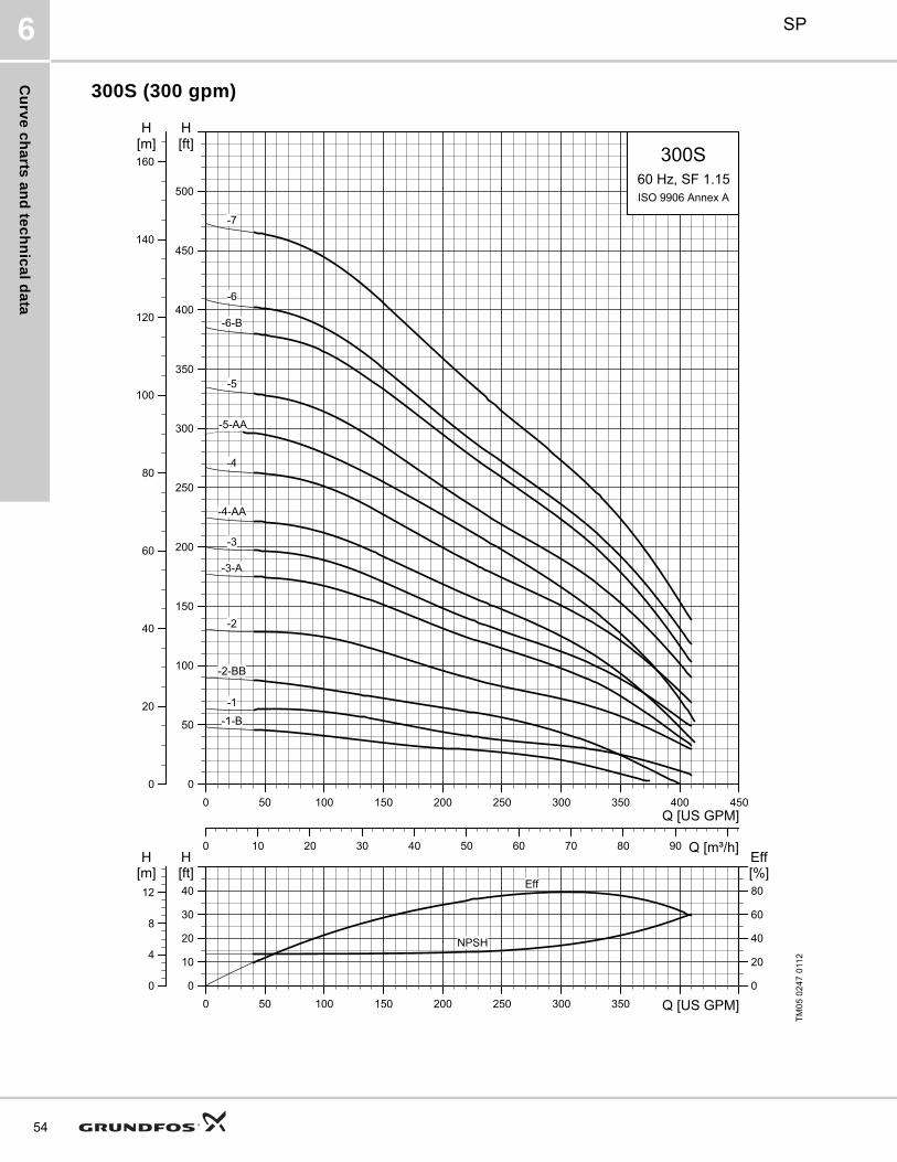
Cu
rve
ch
arts
an
d te
ch
nic
al d
ata
SP6
54
300S (300 gpm)
TM
05
02
47
011
20 50 100 150 200 250 300 350 400 450
Q [US GPM]
0
50
100
150
200
250
300
350
400
450
500
[ft]H
0 10 20 30 40 50 60 70 80 90 Q [m³/h]
0
20
40
60
80
100
120
140
160[m]H
300S60 Hz, SF 1.15ISO 9906 Annex A
-5-AA
-7
-6
-6-B
-5
-4
-4-AA
-3
-3-A
-2
-2-BB
-1
-1-B
0 50 100 150 200 250 300 350 Q [US GPM]0
10
20
30
40[ft]H
0
20
40
60
80[%]Eff
0
4
8
12
[m]H
NPSH
Eff

Cu
rve
ch
art
s a
nd
te
ch
nic
al
da
ta
SP 6
300S (300 gpm)
TM
05
02
48
011
20 50 100 150 200 250 300 350 400 450
Q [US GPM]
100
200
300
400
500
600
700
800
900
1000
1100
1200
1300
[ft]H
0 10 20 30 40 50 60 70 80 90 Q [m³/h]
50
100
150
200
250
300
350
400
[m]H
300S60 Hz, SF 1.15ISO 9906 Annex A-18
-17
-16
-15
-14
-13
-12
-11
-10
-9
-9-B-8
0 50 100 150 200 250 300 350 Q [US GPM]0
10
20
30
40[ft]H
0
20
40
60
80[%]Eff
0
4
8
12
[m]H
NPSH
Eff
55

Cu
rve
ch
arts
an
d te
ch
nic
al d
ata
SP6
56
300S (300 gpm) pump power requirement (P2)
TM
05
02
49
011
2
0 50 100 150 200 250 300 350 400 450Q [US GPM]
0
2
4
6
8
10
12
14
16
18
20
22
24
26
28
30
[hp]P2
0 10 20 30 40 50 60 70 80 90 Q [m³/h]
0
2
4
6
8
10
12
14
16
18
20
22
[kW]P2
300S60 Hz, SF 1.15ISO 9906 Annex A
-5-AA
-7
-6
-6-B
-5
-4
-4-AA-3
-3-A
-2
-2-BB-1
-1-B

Cu
rve
ch
art
s a
nd
te
ch
nic
al
da
ta
SP 6
300S (300 gpm) pump power requirement (P2)
TM
05
02
50
011
20 50 100 150 200 250 300 350 400 450Q [US GPM]
20
25
30
35
40
45
50
55
60
65
70
75
80
[hp]P2
0 10 20 30 40 50 60 70 80 90 Q [m³/h]
15
20
25
30
35
40
45
50
55
60
[kW]P2
300S60 Hz, SF 1.15ISO 9906 Annex A
-18
-17
-16
-15
-14
-13
-12
-11
-10
-9-9-B
-8
57

Cu
rve
ch
arts
an
d te
ch
nic
al d
ata
SP6
58
300S (300 gpm)
Notes:Control box is required for 3-wire, single-phase applications. Data does not include control box.■ MS402 motor.● MS4000 motor.▲ MS6 motor.∧ MMS6000 motor.★ MMS8000 motor.♦ Takes MS6 motor; not available as complete.☼ Takes MMS6000 motor; not available as complete.* Takes MMS8000 motor; not available as complete.† Takes MMS10000 motor; not available as complete.
Pumpmodel
Nom. head[ft]
PhVolts
[V]Motor[Hp]
DimensionsNet
weight(complete)
[lb]
300S
A B C D E
TM
05
111
2 2
111
[in (mm)] [in (mm)] [in (mm)] [in (mm)] [in (mm)]
300S - Motor dia. 4 inch, 3 wire motor, 60 Hz, rated flow 300 gpm (3" NPT)
300S30-1B 19
1 230 3 ● 37.17 (944) 22.72 (577) 14.45 (367) 3.75 (95) 5.83 (148) 72.0
3 230 3 ● 32.41 (823) 17.96 (456) 14.45 (367) 3.75 (95) 5.83 (148) 72.0
3 460 3 ● 32.41 (823) 17.96 (456) 14.45 (367) 3.75 (95) 5.83 (148) 72.0
300S50-1 31
1 230 5 ● 41.11 (1044) 26.65 (677) 14.45 (367) 3.75 (95) 5.83 (148) 74.7
3 230 5 ● 37.13 (943) 22.69 (576) 14.45 (367) 3.75 (95) 5.83 (148) 74.7
3 460 5 ● 37.13 (943) 22.69 (576) 14.45 (367) 3.75 (95) 5.83 (148) 74.7
300S50-2BB 42
1 230 5 ● 45.56 (1157) 26.65 (677) 18.90 (480) 3.75 (95) 5.83 (148) 135.0
3 230 5 ● 41.58 (1056) 22.69 (576) 18.90 (480) 3.75 (95) 5.83 (148) 135.0
3 460 5 ● 41.58 (1056) 22.69 (576) 18.90 (480) 3.75 (95) 5.83 (148) 135.0
300S75-2 703 230 7.5 ● 45.52 (1156) 26.62 (676) 18.90 (480) 3.75 (95) 5.83 (148) 101.7
3 460 7.5 ● 45.52 (1156) 26.62 (676) 18.90 (480) 3.75 (95) 5.83 (148) 101.7
300S100-3A 97 3 460 10 ● 53.90 (1369) 30.56 (776) 23.35 (593) 3.75 (95) 5.83 (148) 145.8
300S - Motor dia. 6 inch, 3 wire motor, 60 Hz, rated flow 300 gpm (3" NPT)
300S75-2 703 230 7.5 ▲ 41.78 (1061) 22.25 (565) 19.53 (496) 5.63 (143) 6.15 (156) 167.4 E = Maximum diameter of pump
including cable guard and motor.3 460 7.5 ▲ 41.78 (1061) 22.25 (565) 19.53 (496) 5.63 (143) 6.15 (156) 167.4
300S100-3A 973 230 10 ▲ 47.21 (1199) 23.23 (590) 23.98 (609) 5.63 (143) 6.15 (156) 216.0
3 460 10 ▲ 47.21 (1199) 23.23 (590) 23.98 (609) 5.63 (143) 6.15 (156) 216.0
300S150-3 1103 230 15 ▲ 51.86 (1317) 27.88 (708) 23.98 (609) 5.63 (143) 6.15 (156) 216.0
3 460 15 ▲ 51.86 (1317) 27.88 (708) 23.98 (609) 5.63 (143) 6.15 (156) 216.0
300S150-4AA 1233 230 15 ▲ 56.30 (1430) 27.88 (708) 28.43 (722) 5.63 (143) 6.15 (156) 222.3
3 460 15 ▲ 56.30 (1430) 27.88 (708) 28.43 (722) 5.63 (143) 6.15 (156) 222.3
300S150-4 1493 230 15 ▲ 56.30 (1430) 27.88 (708) 28.43 (722) 5.63 (143) 6.15 (156) 222.3
3 460 15 ▲ 56.30 (1430) 27.88 (708) 28.43 (722) 5.63 (143) 6.15 (156) 222.3
300S200-5AA 1703 230 20 ▲ 63.71 (1618) 30.83 (783) 32.88 (835) 5.63 (143) 6.15 (156) 194.4
3 460 20 ▲ 63.71 (1618) 30.83 (783) 32.88 (835) 5.63 (143) 6.15 (156) 194.4
300S200-5 1883 230 20 ▲ 63.71 (1618) 30.83 (783) 32.88 (835) 5.63 (143) 6.15 (156) 194.4
3 460 20 ▲ 63.71 (1618) 30.83 (783) 32.88 (835) 5.63 (143) 6.15 (156) 194.4
300S200-6B 2113 230 20 ▲ 68.15 (1731) 30.83 (783) 37.33 (948) 5.63 (143) 6.15 (156) 198.0
3 460 20 ▲ 68.15 (1731) 30.83 (783) 37.33 (948) 5.63 (143) 6.15 (156) 198.0
300S250-6 2283 230 25 ▲ 70.32 (1786) 33.00 (838) 37.33 (948) 5.63 (143) 6.15 (156) 198.0
3 460 25 ▲ 70.32 (1786) 33.00 (838) 37.33 (948) 5.63 (143) 6.15 (156) 198.0A
BC
E
D
NPT

Cu
rve
ch
art
s a
nd
te
ch
nic
al
da
ta
SP 6
300S (300 gpm)
Notes:Control box is required for 3-wire, single-phase applications. Data does not include control box.■ MS402 motor.● MS4000 motor.▲ MS6 motor.∧ MMS6000 motor.★ MMS8000 motor.♦ Takes MS6 motor; not available as complete.☼ Takes MMS6000 motor; not available as complete.* Takes MMS8000 motor; not available as complete.
†Takes MMS10000 motor; not available as complete.
Pumpmodel
Nom. head[ft]
PhVolts
[V]Motor[Hp]
DimensionsNet
weight(complete)
[lb]
300S
A B C D E
TM
05
111
2 2
111
[in (mm)] [in (mm)] [in (mm)] [in (mm)] [in (mm)]
300S - Motor dia. 6 inch, 3 wire motor, 60 Hz, rated flow 300 gpm (4" NPT)
300S250-7AA 2493 230 25 ▲ 74.77 (1899) 33.00 (838) 41.78 (1061) 5.63 (143) 6.15 (156) 217.8
3 460 25 ▲ 74.77 (1899) 33.00 (838) 41.78 (1061) 5.63 (143) 6.15 (156) 217.8
300S300-7 2673 230 25 ▲ 77.33 (1964) 35.56 (903) 41.78 (1061) 5.63 (143) 6.15 (156) 217.8
3 460 25 ▲ 77.33 (1964) 35.56 (903) 41.78 (1061) 5.63 (143) 6.15 (156) 217.8
300S300-8 3073 230 30 ▲ 81.78 (2077) 35.56 (903) 46.23 (1174) 5.63 (143) 6.15 (156) 224.1
3 460 30 ▲ 81.78 (2077) 35.56 (903) 46.23 (1174) 5.63 (143) 6.15 (156) 224.1
300S300-9B 3293 230 30 ▲ 86.23 (2190) 35.56 (903) 50.67 (1287) 5.63 (143) 6.15 (156) 261.0
3 460 30 ▲ 86.23 (2190) 35.56 (903) 50.67 (1287) 5.63 (143) 6.15 (156) 261.0
300S400-9 346 3 460 40 ▲ 90.95 (2310) 40.28 (1023) 50.67 (1287) 5.63 (143) 6.15 (156) 296.0
300S400-10 385 3 460 40 ▲ 95.40 (2423) 40.28 (1023) 55.12 (1400) 5.63 (143) 6.15 (156) 300.5
300S500-11 425 3 460 50 ☼ 115.67 (2938) 56.11 (1425) 59.57 (1513) 5.67 (144) 6.15 (156) 352.0
300S500-12 464 3 460 50 ☼ 120.12 (3051) 56.11 (1425) 64.02 (1626) 5.67 (144) 6.15 (156) 348.8
300S500-13 504 3 460 50 ☼ 124.57 (3164) 56.11 (1425) 68.47 (1739) 5.67 (144) 6.15 (156) 355.1
300S600-14 543 3 460 60 ☼ — — 74.06 (1881) — 6.15 (156) —
300S600-15 582 3 460 60 ☼ — — 74.06 (1881) — 6.15 (156) —
E = Maximum diameter of pump including cable guard and motor.SP 300S - Motor dia. 8 inch, 3 wire motor, 60 Hz, rated flow 230 gpm (4" NPT)
300S600-14 543 3 460 60 * 124.06 (3151) 50.00 (1270) 74.06 (1881) 7.56 (192) 7.56 (192) 479.4
300S600-15 582 3 460 60 * 128.51 (3264) 50.00 (1270) 78.51 (1994) 7.56 (192) 7.56 (192) 519.4
300S750-16 622 3 460 75 * 136.11 (3457) 53.15 (1350) 82.96 (2107) 7.56 (192) 7.56 (192) 569.1
300S750-17 661 3 460 75 * 140.56 (3570) 53.15 (1350) 87.41 (2220) 7.56 (192) 7.56 (192) 575.4
300S750-18 701 3 460 75 * 145.00 (3683) 53.15 (1350) 91.86 (2333) 7.56 (192) 7.56 (192) 581.7
A
BC
E
D
NPT
59

Cu
rve
ch
arts
an
d te
ch
nic
al d
ata
SP6
60
385S (385 gpm)
TM
05
02
51
011
20 50 100 150 200 250 300 350 400 450 500 550
Q [US GPM]
0
50
100
150
200
250
300
350
400
450
500
550
[ft]H
0 10 20 30 40 50 60 70 80 90 100 110 Q [m³/h]
0
20
40
60
80
100
120
140
160
[m]H
385S60 Hz, SF 1.15ISO 9906 Annex A-6-B
-5
-5-BB
-4
-4-B
-3
-3-A
-2
-2-BA
-1
0 50 100 150 200 250 300 350 400 450 Q [US GPM]0
10
20
30
40[ft]H
0
20
40
60
80[%]Eff
0
4
8
12
[m]H
NPSH
Eff

Cu
rve
ch
art
s a
nd
te
ch
nic
al
da
ta
SP 6
385S (385 gpm)
TM
05
02
52
011
20 50 100 150 200 250 300 350 400 450 500 550
Q [US GPM]
100
200
300
400
500
600
700
800
900
1000
1100
1200
1300
[ft]H
0 10 20 30 40 50 60 70 80 90 100 110 Q [m³/h]
50
100
150
200
250
300
350
400
[m]H
385S60 Hz, SF 1.15ISO 9906 Annex A-13
-12
-11
-10
-9
-8
-7
-6
0 50 100 150 200 250 300 350 400 450 Q [US GPM]0
10
20
30
40[ft]H
0
20
40
60
80[%]Eff
0
4
8
12
[m]H
NPSH
Eta
61
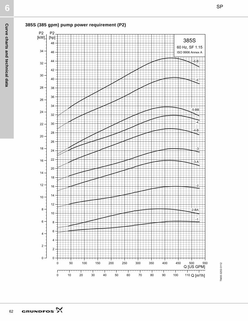
Cu
rve
ch
arts
an
d te
ch
nic
al d
ata
SP6
62
385S (385 gpm) pump power requirement (P2)
TM
05
02
53
011
20 50 100 150 200 250 300 350 400 450 500 550Q [US GPM]
0
2
4
6
8
10
12
14
16
18
20
22
24
26
28
30
32
34
36
38
40
42
44
46
48
[hp]P2
0 10 20 30 40 50 60 70 80 90 100 110 Q [m³/h]
0
2
4
6
8
10
12
14
16
18
20
22
24
26
28
30
32
34
[kW]P2
385S60 Hz, SF 1.15ISO 9906 Annex A
-6-B
-5
-5-BB
-4
-4-B
-3
-3-A
-2
-2-BA
-1
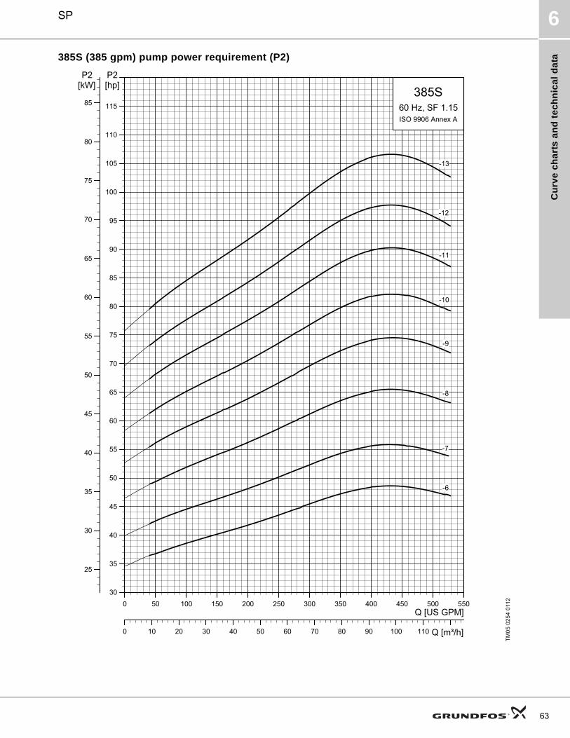
Cu
rve
ch
art
s a
nd
te
ch
nic
al
da
ta
SP 6
385S (385 gpm) pump power requirement (P2)
TM
05
02
54
011
2
0 50 100 150 200 250 300 350 400 450 500 550Q [US GPM]
30
35
40
45
50
55
60
65
70
75
80
85
90
95
100
105
110
115
[hp]P2
0 10 20 30 40 50 60 70 80 90 100 110 Q [m³/h]
25
30
35
40
45
50
55
60
65
70
75
80
85
[kW]P2
385S60 Hz, SF 1.15ISO 9906 Annex A
-13
-12
-11
-10
-9
-8
-7
-6
63
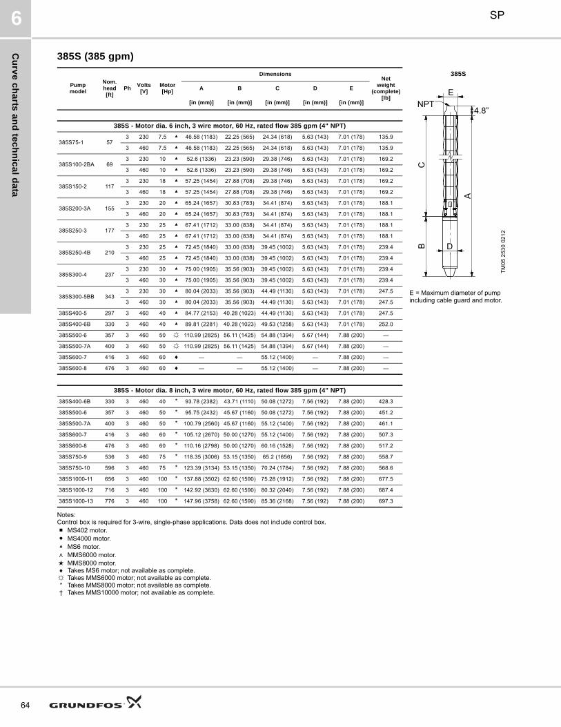
Cu
rve
ch
arts
an
d te
ch
nic
al d
ata
SP6
64
385S (385 gpm)
Notes:Control box is required for 3-wire, single-phase applications. Data does not include control box.■ MS402 motor.● MS4000 motor.▲ MS6 motor.∧ MMS6000 motor.★ MMS8000 motor.♦ Takes MS6 motor; not available as complete.☼ Takes MMS6000 motor; not available as complete.* Takes MMS8000 motor; not available as complete.† Takes MMS10000 motor; not available as complete.
Pumpmodel
Nom. head[ft]
PhVolts
[V]Motor[Hp]
DimensionsNet
weight(complete)
[lb]
385S
A B C D E
TM
05
25
30
02
12
[in (mm)] [in (mm)] [in (mm)] [in (mm)] [in (mm)]
385S - Motor dia. 6 inch, 3 wire motor, 60 Hz, rated flow 385 gpm (4" NPT)
385S75-1 573 230 7.5 ▲ 46.58 (1183) 22.25 (565) 24.34 (618) 5.63 (143) 7.01 (178) 135.9
3 460 7.5 ▲ 46.58 (1183) 22.25 (565) 24.34 (618) 5.63 (143) 7.01 (178) 135.9
385S100-2BA 693 230 10 ▲ 52.6 (1336) 23.23 (590) 29.38 (746) 5.63 (143) 7.01 (178) 169.2
3 460 10 ▲ 52.6 (1336) 23.23 (590) 29.38 (746) 5.63 (143) 7.01 (178) 169.2
385S150-2 1173 230 18 ▲ 57.25 (1454) 27.88 (708) 29.38 (746) 5.63 (143) 7.01 (178) 169.2
3 460 18 ▲ 57.25 (1454) 27.88 (708) 29.38 (746) 5.63 (143) 7.01 (178) 169.2
385S200-3A 1553 230 20 ▲ 65.24 (1657) 30.83 (783) 34.41 (874) 5.63 (143) 7.01 (178) 188.1
3 460 20 ▲ 65.24 (1657) 30.83 (783) 34.41 (874) 5.63 (143) 7.01 (178) 188.1
385S250-3 1773 230 25 ▲ 67.41 (1712) 33.00 (838) 34.41 (874) 5.63 (143) 7.01 (178) 188.1
3 460 25 ▲ 67.41 (1712) 33.00 (838) 34.41 (874) 5.63 (143) 7.01 (178) 188.1
385S250-4B 2103 230 25 ▲ 72.45 (1840) 33.00 (838) 39.45 (1002) 5.63 (143) 7.01 (178) 239.4
3 460 25 ▲ 72.45 (1840) 33.00 (838) 39.45 (1002) 5.63 (143) 7.01 (178) 239.4
385S300-4 2373 230 30 ▲ 75.00 (1905) 35.56 (903) 39.45 (1002) 5.63 (143) 7.01 (178) 239.4
3 460 30 ▲ 75.00 (1905) 35.56 (903) 39.45 (1002) 5.63 (143) 7.01 (178) 239.4
385S300-5BB 3433 230 30 ▲ 80.04 (2033) 35.56 (903) 44.49 (1130) 5.63 (143) 7.01 (178) 247.5 E = Maximum diameter of pump
including cable guard and motor.3 460 30 ▲ 80.04 (2033) 35.56 (903) 44.49 (1130) 5.63 (143) 7.01 (178) 247.5
385S400-5 297 3 460 40 ▲ 84.77 (2153) 40.28 (1023) 44.49 (1130) 5.63 (143) 7.01 (178) 247.5
385S400-6B 330 3 460 40 ▲ 89.81 (2281) 40.28 (1023) 49.53 (1258) 5.63 (143) 7.01 (178) 252.0
385S500-6 357 3 460 50 ☼ 110.99 (2825) 56.11 (1425) 54.88 (1394) 5.67 (144) 7.88 (200) —
385S500-7A 400 3 460 50 ☼ 110.99 (2825) 56.11 (1425) 54.88 (1394) 5.67 (144) 7.88 (200) —
385S600-7 416 3 460 60 ♦ — — 55.12 (1400) — 7.88 (200) —
385S600-8 476 3 460 60 ♦ — — 55.12 (1400) — 7.88 (200) —
385S - Motor dia. 8 inch, 3 wire motor, 60 Hz, rated flow 385 gpm (4" NPT)
385S400-6B 330 3 460 40 * 93.78 (2382) 43.71 (1110) 50.08 (1272) 7.56 (192) 7.88 (200) 428.3
385S500-6 357 3 460 50 * 95.75 (2432) 45.67 (1160) 50.08 (1272) 7.56 (192) 7.88 (200) 451.2
385S500-7A 400 3 460 50 * 100.79 (2560) 45.67 (1160) 55.12 (1400) 7.56 (192) 7.88 (200) 461.1
385S600-7 416 3 460 60 * 105.12 (2670) 50.00 (1270) 55.12 (1400) 7.56 (192) 7.88 (200) 507.3
385S600-8 476 3 460 60 * 110.16 (2798) 50.00 (1270) 60.16 (1528) 7.56 (192) 7.88 (200) 517.2
385S750-9 536 3 460 75 * 118.35 (3006) 53.15 (1350) 65.2 (1656) 7.56 (192) 7.88 (200) 558.7
385S750-10 596 3 460 75 * 123.39 (3134) 53.15 (1350) 70.24 (1784) 7.56 (192) 7.88 (200) 568.6
385S1000-11 656 3 460 100 * 137.88 (3502) 62.60 (1590) 75.28 (1912) 7.56 (192) 7.88 (200) 677.5
385S1000-12 716 3 460 100 * 142.92 (3630) 62.60 (1590) 80.32 (2040) 7.56 (192) 7.88 (200) 687.4
385S1000-13 776 3 460 100 * 147.96 (3758) 62.60 (1590) 85.36 (2168) 7.56 (192) 7.88 (200) 697.3
A
BC
E
D
NPT4.8”

Cu
rve
ch
art
s a
nd
te
ch
nic
al
da
ta
SP 6
475S (475 gpm)
TM
05
02
55
011
20 100 200 300 400 500 600 700
Q [US GPM]
0
50
100
150
200
250
300
350
400
450
500
[ft]H
0 25 50 75 100 125 Q [m³/h]
0
20
40
60
80
100
120
140
160[m]H
475S60 Hz, SF 1.15ISO 9906 Annex A
-3-A
-5-B
-4
-4-AB
-3
-3-B
-3-BB
-2
-2-B
-1
-1-A
0 100 200 300 400 500 Q [US GPM]0
10
20
30
40[ft]H
0
20
40
60
80[%]Eff
0
4
8
12
[m]H
NPSH
Eff
TM05
0255
0811
65

Cu
rve
ch
arts
an
d te
ch
nic
al d
ata
SP6
66
475S (475 gpm)
TM
05
02
56
011
20 100 200 300 400 500 600 700
Q [US GPM]
100
200
300
400
500
600
700
800
900
1000
1100
1200
1300
[ft]H
0 25 50 75 100 125 Q [m³/h]
50
100
150
200
250
300
350
400
[m]H
475S60 Hz, SF 1.15ISO 9906 Annex A
-6-A
-13
-12
-11
-10
-9
-8
-7
-6
-5
0 100 200 300 400 500 Q [US GPM]0
10
20
30
40[ft]H
0
20
40
60
80[%]Eff
0
4
8
12
[m]H
NPSH
Eff

Cu
rve
ch
art
s a
nd
te
ch
nic
al
da
ta
SP 6
475S (475 gpm) pump power requirement (P2)
TM
05
02
57
011
20 100 200 300 400 500 600 700Q [US GPM]
0
4
8
12
16
20
24
28
32
36
40
44
48
[hp]P2
0 25 50 75 100 125 Q [m³/h]
0
4
8
12
16
20
24
28
32
36
[kW]P2
475S60 Hz, SF 1.15ISO 9906 Annex A
-5-B
-4
-4-AB
-3
-3-B
-3-BB
-2
-2-B
-1
-1-A
67

Cu
rve
ch
arts
an
d te
ch
nic
al d
ata
SP6
68
475S (475 gpm) pump power requirement (P2)
TM
05
02
58
011
2
0 100 200 300 400 500 600 700Q [US GPM]
30
40
50
60
70
80
90
100
110
120
130
[hp]P2
0 25 50 75 100 125 Q [m³/h]
30
40
50
60
70
80
90
100[kW]P2
475S60 Hz, SF 1.15ISO 9906 Annex A
-13
-12
-11
-10
-9
-8
-7
-6
-5

Cu
rve
ch
art
s a
nd
te
ch
nic
al
da
ta
SP 6
475S (475 gpm)
Notes:Control box is required for 3-wire, single-phase applications. Data does not include control box.■ MS402 motor.● MS4000 motor.▲ MS6 motor.∧ MMS6000 motor.★ MMS8000 motor.♦ Takes MS6 motor; not available as complete.☼ Takes MMS6000 motor; not available as complete.* Takes MMS8000 motor; not available as complete.† Takes MMS10000 motor; not available as complete.
Pumpmodel
Nom. head[ft]
PhVolts
[V]Motor[Hp]
DimensionsNet
weight(complete)
[lb]
475S
A B C D E
TM
05
25
31
02
12
[in (mm)] [in (mm)] [in (mm)] [in (mm)] [in (mm)]
475S - Motor dia. 6 inch, 3 wire motor, 60 Hz, rated flow 475 gpm (5" NPT)
475S75-1A 423 230 7.5 ▲ 46.58 (1183) 22.25 (565) 24.34 (618) 5.63 (143) 7.05 (179) 132.3
3 460 7.5 ▲ 46.58 (1183) 22.25 (565) 24.34 (618) 5.63 (143) 7.05 (179) 132.3
475S100-1 583 230 10 ▲ 47.56 (1208) 23.23 (590) 24.34 (618) 5.63 (143) 7.05 (179) 132.3
3 460 10 ▲ 47.56 (1208) 23.23 (590) 24.34 (618) 5.63 (143) 7.05 (179) 132.3
475S150-2B 893 230 15 ▲ 57.25 (1454) 27.88 (708) 29.38 (746) 5.63 (143) 7.05 (179) 170.1
3 460 15 ▲ 57.25 (1454) 27.88 (708) 29.38 (746) 5.63 (143) 7.05 (179) 170.1
475S200-2 1173 230 20 ▲ 60.20 (1529) 30.83 (783) 29.38 (746) 5.63 (143) 7.05 (179) 198.7
3 460 20 ▲ 60.20 (1529) 30.83 (783) 29.38 (746) 5.63 (143) 7.05 (179) 198.7
475S250-3A 1663 230 25 ▲ 67.41 (1712) 33.00 (838) 34.41 (874) 5.63 (143) 7.05 (179) 218.2
3 460 25 ▲ 67.41 (1712) 33.00 (838) 34.41 (874) 5.63 (143) 7.05 (179) 218.2
475S300-3 1773 230 30 ▲ 69.97 (1777) 35.56 (903) 34.41 (874) 5.63 (143) 7.05 (179) 233.6
3 460 30 ▲ 69.97 (1777) 35.56 (903) 34.41 (874) 5.63 (143) 7.05 (179) 233.6
475S300-4AB 1683 230 30 ▲ 75.00 (1905) 35.56 (903) 39.45 (1002) 5.63 (143) 7.05 (179) 239.9
3 460 30 ▲ 75.00 (1905) 35.56 (903) 39.45 (1002) 5.63 (143) 7.05 (179) 239.9
475S400-4 236 3 460 40 ▲ 79.73 (2025) 40.28 (1023) 39.45 (1002) 5.63 (143) 7.05 (179) 268.5 E = Maximum diameter of pump including cable guard and motor.
475S - Motor dia. 6 inch, 3 wire motor, 60 Hz, rated flow 475 gpm (6" NPT)
475S400-5B 268 3 460 40 ▲ 84.77 (2153) 40.28 (1023) 44.49 (1130) 5.63 (143) 7.05 (179) 356.0
475S500-5 296 3 460 50 ☼ 100.6 (2555) 56.11 (1425) 44.49 (1130) 5.67 (144) 7.05 (179) 384.0
475S500-6A 344 3 460 50 ☼ 105.63 (2683) 56.11 (1425) 49.53 (1258) 5.67 (144) 7.05 (179) 385.0
475S600-6 355 3 460 60 ♦ — — 50.08 (1272) — 7.05 (179) —
475S600-7 415 3 460 60 ♦ — — 55.12 (1400) — 7.05 (179) —
475S - Motor dia. 8 inch, 3 wire motor, 60 Hz, rated flow 475 gpm (6" NPT)
475S400-4 236 3 460 40 * 83.71 (2126) 43.71 (1110) 40.00 (1016) 7.56 (192) 8.08 (205) 406.5
475S400-5B 268 3 460 40 * 88.75 (2254) 43.71 (1110) 45.04 (1144) 7.56 (192) 8.08 (205) —
475S500-5 296 3 460 50 * 90.71 (2304) 45.67 (1160) 45.04 (1144) 7.56 (192) 8.08 (205) 420.4
475S500-6A 344 3 460 50 * 95.75 (2432) 45.67 (1160) 50.08 (1272) 7.56 (192) 8.08 (205) —
475S600-6 355 3 460 60 * 100.08 (2542) 50.00 (1270) 50.08 (1272) 7.56 (192) 8.08 (205) 476.0
475S600-7 415 3 460 60 * 105.12 (2670) 50.00 (1270) 55.12 (1400) 7.56 (192) 8.08 (205) 482.6
475S750-8 534 3 460 75 * 113.31 (2878) 53.15 (1350) 60.16 (1528) 7.56 (192) 8.08 (205) 524.4
475S1000-9 534 3 460 100 * 127.8 (3246) 62.60 (1590) 65.20 (1656) 7.56 (192) 8.08 (205) 631.0
475S1000-10 593 3 460 100 * 132.84 (3374) 62.60 (1590) 70.24 (1784) 7.56 (192) 8.08 (205) 637.6
475S1000-11 653 3 460 100 * 137.88 (3502) 62.60 (1590) 75.28 (1912) 7.56 (192) 8.08 (205) 644.3
475S1250-12 712 3 460 125 * 152.37 (3870) 72.05 (1830) 80.32 (2040) 7.56 (192) 8.08 (205) 754.1
475S1250-13 772 3 460 125 * 157.41 (3998) 72.05 (1830) 85.36 (2168) 7.56 (192) 8.08 (205) 760.7
A
BC
E
D
NPT6.1”
69

Cu
rve
ch
arts
an
d te
ch
nic
al d
ata
SP6
70
625S (625 gpm)
TM
05
02
59
011
20 100 200 300 400 500 600 700 800 900
Q [US GPM]
0
50
100
150
200
250
300
350
400
450
500
550
[ft]H
0 25 50 75 100 125 150 175 Q [m³/h]
0
20
40
60
80
100
120
140
160
[m]H
625S60 Hz, SF 1.15ISO 9906 Annex A
-4
-4-A
-4-AA
-3
-3-A
-3-AA
-2
-2-A
-2-AA
-1
-1-A
0 100 200 300 400 500 600 700 Q [US GPM]0
10
20
30
40[ft]H
0
20
40
60
80[%]Eff
0
4
8
12
[m]H
NPSH
Eff

Cu
rve
ch
art
s a
nd
te
ch
nic
al
da
ta
SP 6
625S (625 gpm)
TM
05
02
60
011
20 100 200 300 400 500 600 700 800 900
Q [US GPM]
200
300
400
500
600
700
800
900
1000
[ft]H
0 25 50 75 100 125 150 175 Q [m³/h]
100
150
200
250
300
[m]H
625S60 Hz, SF 1.15ISO 9906 Annex A
-7
-7-A
-7-AA
-6
-6-AA
-5
-5-A
-5-AA
0 100 200 300 400 500 600 700 Q [US GPM]0
10
20
30
40[ft]H
0
20
40
60
80[%]Eff
0
4
8
12
[m]H
NPSH
Eff
71

Cu
rve
ch
arts
an
d te
ch
nic
al d
ata
SP6
72
625S (625 gpm) pump power requirement (P2)
TM
05
02
61
011
20 100 200 300 400 500 600 700 800 900Q [US GPM]
5
10
15
20
25
30
35
40
45
50
55
60
65
70
75
80
85
90
95
[hp]P2
0 25 50 75 100 125 150 175 Q [m³/h]
5
10
15
20
25
30
35
40
45
50
55
60
65
70
[kW]P2
625S60 Hz, SF 1.15ISO 9906 Annex A
-4
-4-A
-4-AA
-3
-3-A
-3-AA
-2
-2-A
-2-AA
-1
-1-A

Cu
rve
ch
art
s a
nd
te
ch
nic
al
da
ta
SP 6
625S (625 gpm) pump power requirement (P2)
TM
05
02
62
011
20 100 200 300 400 500 600 700 800 900Q [US GPM]
50
60
70
80
90
100
110
120
130
140
150
160
[hp]P2
0 25 50 75 100 125 150 175 Q [m³/h]
40
50
60
70
80
90
100
110
120
[kW]P2
625S60 Hz, SF 1.15ISO 9906 Annex A
-7
-7-A
-7-AA
-6
-6-AA
-5
-5-A
-5-AA
73

Cu
rve
ch
arts
an
d te
ch
nic
al d
ata
SP6
74
625S (625 gpm)
Notes:Control box is required for 3-wire, single-phase applications. Data does not include control box.■ MS402 motor.● MS4000 motor.▲ MS6 motor.∧ MMS6000 motor.★ MMS8000 motor.♦ Takes MS6 motor; not available as complete.☼ Takes MMS6000 motor; not available as complete.* Takes MMS8000 motor; not available as complete.† Takes MMS10000 motor; not available as complete.
Pumpmodel
Nom. head[ft]
PhVolts
[V]Motor[Hp]
DimensionsNet
weight(complete)
[lb]
625S
A B C D E
TM
05
25
31
02
12
[in (mm)] [in (mm)] [in (mm)] [in (mm)] [in (mm)]
625S - Motor dia. 6 inch, 3 wire motor, 60 Hz, rated flow 625 gpm (6" NPT)
625S150-1A 653 230 15 ▲ 53.51 (1359) 27.88 (708) 25.63 (651) 5.63 (143) 8.31 (211) 193.0
3 460 15 ▲ 53.51 (1359) 27.88 (708) 25.63 (651) 5.63 (143) 8.31 (211) 193.0
625S250-1 953 230 25 ▲ 58.63 (1489) 33.00 (838) 25.63 (651) 5.63 (143) 8.31 (211) 189.9
3 460 25 ▲ 58.63 (1489) 33.00 (838) 25.63 (651) 5.63 (143) 8.31 (211) 198.9
625S300-2AA 1303 230 30 ▲ 67.33 (1710) 35.56 (903) 31.78 (807) 5.63 (143) 8.31 (211) 213.0
3 460 30 ▲ 67.33 (1710) 35.56 (903) 31.78 (807) 5.63 (143) 8.31 (211) 222.3
625S400-2A 159 3 460 40 ▲ 72.05 (1830) 40.28 (1023) 31.78 (807) 5.63 (143) 8.31 (211) 333.8
625S400-2 194 3 460 40 ▲ 72.05 (1830) 40.28 (1023) 31.78 (807) 5.63 (143) 8.31 (211) 333.8
625S500-3AA 224 3 460 50 ♦ 94.02 (2388) 56.11 (1425) 37.94 (963) 5.63 (143) 8.31 (211) 376.4
625S600-3A 258 3 460 60 ♦ — — 37.92 (963) — 8.31 (211) —
625S600-3 292 3 460 60 ♦ — — 37.92 (963) — 8.31 (211) —
625S - Motor dia. 8 inch, 3 wire motor, 60 Hz, rated flow 625 gpm (6" NPT)
625S400-2 194 3 460 40 * 76.03 (1931) 43.71 (1110) 32.33 (821) 7.56 (192) 8.39 (213) 409.4
625S500-3AA 224 3 460 50 * 83.59 (2123) 45.67 (1160) 37.92 (963) 7.56 (192) 8.39 (213) 444.6 E = Maximum diameter of pump including cable guard and motor.625S600-3A 258 3 460 60 * 87.92 (2233) 50.00 (1270) 37.92 (963) 7.56 (192) 8.39 (213) 490.8
625S600-3 292 3 460 60 * 87.92 (2233) 50.00 (1270) 37.92 (963) 7.56 (192) 8.39 (213) 490.8
625S750-4AA 322 3 460 75 * 97.21 (2469) 53.15 (1350) 44.06 (1119) 7.56 (192) 8.39 (213) 534.8
625S750-4A 357 3 460 75 * 97.21 (2469) 53.15 (1350) 44.06 (1119) 7.56 (192) 8.39 (213) 534.8
625S1000-4 391 3 460 100 * 106.66 (2709) 62.60 (1590) 44.06 (1119) 7.56 (192) 8.39 (213) 633.8
6251000-5AA 421 3 460 100 * 112.76 (2864) 62.60 (1590) 50.16 (1274) 7.56 (192) 8.39 (213) 649.3
625S1000-5A 455 3 460 100 * 112.76 (2864) 62.60 (1590) 50.16 (1274) 7.56 (192) 8.39 (213) 649.3
625S1000-5 490 3 460 100 * 112.76 (2864) 62.60 (1590) 50.16 (1274) 7.56 (192) 8.39 (213) 649.3
625S1250-6AA 520 3 460 125 * 128.31 (3259) 72.05 (1830) 56.26 (1429) 7.56 (192) 8.39 (213) 761.5
625S1250-6 554 3 460 125 * 128.31 (3259) 72.05 (1830) 56.26 (1429) 7.56 (192) 8.39 (213) 761.5
625S1250-7AA 618 3 460 125 * 134.45 (3415) 72.05 (1830) 62.41 (1585) 7.56 (192) 8.39 (213) 774.7
625S1500-7A 653 3 460 150 * 143.51 (3645) 81.11 (2060) 62.41 (1585) 7.56 (192) 8.39 (213) 884.7
625S1500-7 687 3 460 150 * 143.51 (3645) 81.11 (2060) 62.41 (1585) 7.56 (192) 8.39 (213) 884.7
AB
C
E
D
NPT
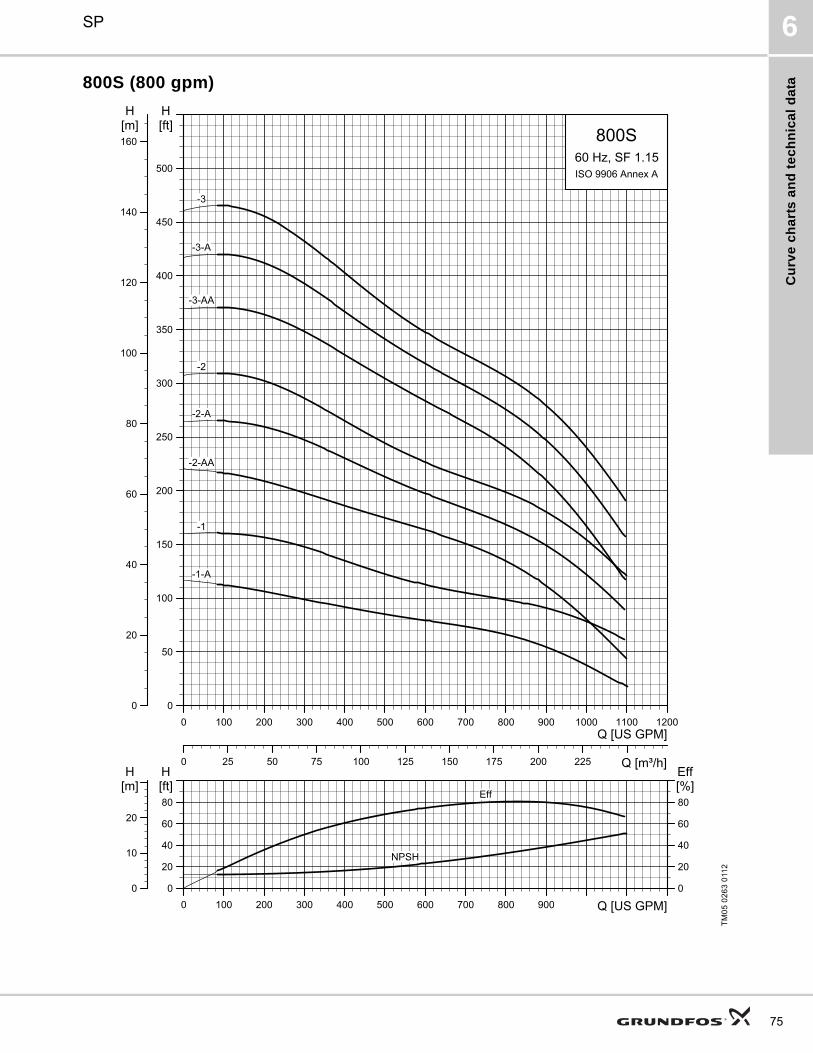
Cu
rve
ch
art
s a
nd
te
ch
nic
al
da
ta
SP 6
800S (800 gpm)
TM
05
02
63
011
20 100 200 300 400 500 600 700 800 900 1000 1100 1200
Q [US GPM]
0
50
100
150
200
250
300
350
400
450
500
[ft]H
0 25 50 75 100 125 150 175 200 225 Q [m³/h]
0
20
40
60
80
100
120
140
160[m]H
800S60 Hz, SF 1.15ISO 9906 Annex A
-3
-3-A
-3-AA
-2
-2-A
-2-AA
-1
-1-A
0 100 200 300 400 500 600 700 800 900 Q [US GPM]0
20
40
60
80[ft]H
0
20
40
60
80[%]Eff
0
10
20
[m]H
NPSH
Eff
75

Cu
rve
ch
arts
an
d te
ch
nic
al d
ata
SP6
76
800S (800 gpm)
TM
05
02
64
011
20 100 200 300 400 500 600 700 800 900 1000 1100 1200
Q [US GPM]
100
200
300
400
500
600
700
800
[ft]H
0 25 50 75 100 125 150 175 200 225 Q [m³/h]
50
100
150
200
250
[m]H
800S60 Hz, SF 1.15ISO 9906 Annex A
-5
-5-A
-5-AA
-4
-4-AA
-4-A
0 100 200 300 400 500 600 700 800 900 Q [US GPM]0
20
40
60
80[ft]H
0
20
40
60
80[%]Eff
0
10
20
[m]H
NPSH
Eff

Cu
rve
ch
art
s a
nd
te
ch
nic
al
da
ta
SP 6
800S (800 gpm) pump power requirement (P2)
TM
05
02
65
011
20 100 200 300 400 500 600 700 800 900 1000 1100 1200Q [US GPM]
5
10
15
20
25
30
35
40
45
50
55
60
65
70
75
80
85
90
95
[hp]P2
0 25 50 75 100 125 150 175 200 225 Q [m³/h]
5
10
15
20
25
30
35
40
45
50
55
60
65
70
[kW]P2
800S60 Hz, SF 1.15ISO 9906 Annex A
-3
-3-A
-3-AA
-2
-2-A
-2-AA
-1
-1-A
77

Cu
rve
ch
arts
an
d te
ch
nic
al d
ata
SP6
78
800S (800 gpm) pump power requirement (P2)
TM
05
02
66
08
110 100 200 300 400 500 600 700 800 900 1000 1100 1200Q [US GPM]
60
65
70
75
80
85
90
95
100
105
110
115
120
125
130
135
140
[hp]P2
0 25 50 75 100 125 150 175 200 225 Q [m³/h]
45
50
55
60
65
70
75
80
85
90
95
100
[kW]P2
SP 800S60 Hz, SF 1.15ISO 9906 Annex A
-5
-5-A
-5-AA
-4
-4-A
-4-AA

Cu
rve
ch
art
s a
nd
te
ch
nic
al
da
ta
SP 6
800S (800 gpm)
Notes:Control box is required for 3-wire, single-phase applications. Data does not include control box.■ MS402 motor.● MS4000 motor.▲ MS6 motor.∧ MMS6000 motor.★ MMS8000 motor.♦ Takes MS6 motor; not available as complete.☼ Takes MMS6000 motor; not available as complete.* Takes MMS8000 motor; not available as complete.† Takes MMS10000 motor; not available as complete.
Pumpmodel
Nom. head[ft]
PhVolts
[V]Motor[Hp]
DimensionsNet
weight(complete)
[lb]
800S
A B C D E
TM
05
5 2
53
2 0
21
2
[in (mm)] [in (mm)] [in (mm)] [in (mm)] [in (mm)]
800S - Motor dia. 6 inch, 3 wire motor, 60 Hz, rated flow 800 gpm (6" NPT)
800S200-1A 643 230 20 ▲ 56.50 (1435) 30.83 (783) 25.67 (652) 5.63 (143) 8.31 (211) 180.0
3 460 20 ▲ 56.50 (1435) 30.83 (783) 25.67 (652) 5.63 (143) 8.31 (211) 180.0
800S300-1 963 230 30 ▲ 61.23 (1555) 35.56 (903) 25.67 (652) 5.63 (143) 8.31 (211) 202.5
3 460 30 ▲ 61.23 (1555) 35.56 (903) 25.67 (652) 5.63 (143) 8.31 (211) 202.5
800S400-2AA 131 3 460 35 ▲ 72.05 (1830) 40.28 (1023) 31.78 (807) 5.63 (143) 8.31 (211) 257.4
800S500-2A 162 3 460 50 ☼ 88.00 (2235) 56.11 (1425) 31.87 (810) 7.56 (192) 8.39 (213) 363.2
800S500-2 194 3 460 50 ☼ 88.00 (2235) 56.11 (1425) 31.87 (810) 7.56 (192) 8.39 (213) 363.2
800S600-3AA 197 3 460 60 ♦ — — 37.92 (963) — 8.39 (213) —
800S - Motor dia. 8 inch, 3 wire motor, 60 Hz, rated flow 800 gpm (6" NPT)
800S400-2AA 131 3 460 40 * 75.48 (1917) 43.71 (1110) 31.78 (807) 7.56 (192) 8.39 (213) 409.4
800S500-2A 162 3 460 50 * 77.45 (1967) 45.67 (1160) 31.78 (807) 7.56 (192) 8.39 (213) 431.4
800S500-2 187 3 460 50 * 77.45 (1967) 45.67 (1160) 31.78 (807) 7.56 (192) 8.39 (213) 438.0
800S600-3AA 229 3 460 60 * 87.92 (2233) 50.00 (1270) 37.92 (963) 7.56 (192) 8.39 (213) 490.8
800S750-3A 260 3 460 75 * 91.07 (2313) 53.15 (1350) 37.92 (963) 7.56 (192) 8.39 (213) 523.8 E = Maximum diameter of pump including cable guard and motor.800S750-3 292 3 460 75 * 91.07 (2313) 53.15 (1350) 37.92 (963) 7.56 (192) 8.39 (213) 523.8
800S1000-4AA 327 3 460 100 * 106.62 (2708) 62.60 (1590) 44.02 (1118) 7.56 (192) 8.39 (213) 633.8
800S1000-4A 358 3 460 100 * 106.62 (2708) 62.60 (1590) 44.02 (1118) 7.56 (192) 8.39 (213) 633.8
800S1000-4 389 3 460 100 * 106.62 (2708) 62.60 (1590) 44.02 (1118) 7.56 (192) 8.39 (213) 633.8
800S1250-5AA 426 3 460 125 * 122.21 (3104) 72.05 (1830) 50.16 (1274) 7.56 (192) 8.39 (213) 748.3
800S1250-5A 456 3 460 125 * 122.21 (3104) 72.05 (1830) 50.16 (1274) 7.56 (192) 8.39 (213) 748.3
800S1250-5 487 3 460 125 * 122.21 (3104) 72.05 (1830) 50.16 (1274) 7.56 (192) 8.39 (213) 746.6
AB
C
E
D
NPT
79

Cu
rve
ch
arts
an
d te
ch
nic
al d
ata
SP6
80
1100S (1100 gpm)
TM
05
02
67
46
11
0 200 400 600 800 1000 1200 1400 1600Q [US GPM]
0
50
100
150
200
250
300
350
400
450
500
550
[ft]H
0 50 100 150 200 250 300 Q [m³/h]
0
20
40
60
80
100
120
140
160
[m]H
1100S60 Hz, SF 1.15ISO 9906 Annex A
-3
-3-A
-3-AA
-2
-2-A
-2-AA
-1
-1-A
0 200 400 600 800 1000 1200 Q [US GPM]
0
20
40
60
80
[ft]H
0
20
40
60
80
[%]Eff
0
10
20
[m]H
NPSH
Eff

Cu
rve
ch
art
s a
nd
te
ch
nic
al
da
ta
SP 6
1100S (1100 gpm)
TM
05
02
68
011
20 200 400 600 800 1000 1200 1400 1600
Q [US GPM]
100
200
300
400
500
600
700
800
900
1000
1100
[ft]H
0 50 100 150 200 250 300 Q [m³/h]
50
100
150
200
250
300
350[m]H
1100S60 Hz, SF 1.15ISO 9906 Annex A
-6
-6-A
-6-AA
-5
-5-A
-5-AA
-4
-4-A
-4-AA
0 200 400 600 800 1000 1200 Q [US GPM]0
20
40
60
80[ft]H
0
20
40
60
80[%]Eff
0
10
20
[m]H
NPSH
Eff
81
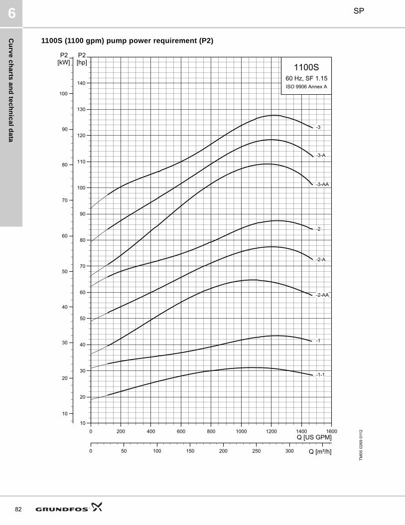
Cu
rve
ch
arts
an
d te
ch
nic
al d
ata
SP6
82
1100S (1100 gpm) pump power requirement (P2)
TM
05
02
69
011
20 200 400 600 800 1000 1200 1400 1600Q [US GPM]
10
20
30
40
50
60
70
80
90
100
110
120
130
140
[hp]P2
0 50 100 150 200 250 300 Q [m³/h]
10
20
30
40
50
60
70
80
90
100
[kW]P2
1100S60 Hz, SF 1.15ISO 9906 Annex A
-3
-3-A
-3-AA
-2
-2-A
-2-AA
-1
-1-1

Cu
rve
ch
art
s a
nd
te
ch
nic
al
da
ta
SP 6
1100S (1100 gpm) pump power requirement (P2)
TM
05
02
70
011
20 200 400 600 800 1000 1200 1400 1600Q [US GPM]
60
80
100
120
140
160
180
200
220
240
260
280
[hp]P2
0 50 100 150 200 250 300 Q [m³/h]
60
80
100
120
140
160
180
200
[kW]P2
1100S60 Hz, SF 1.15ISO 9906 Annex A
-6
-6-A
-6-AA
-5
-5-A
-5-AA
-4
-4-A
-4-AA
83

Cu
rve
ch
arts
an
d te
ch
nic
al d
ata
SP6
84
1100S (1100 gpm)
Notes:Control box is required for 3-wire, single-phase applications. Data does not include control box.■ MS402 motor.● MS4000 motor.▲ MS6 motor.∧ MMS6000 motor.★ MMS8000 motor.♦ Takes MS6 motor; not available as complete.☼ Takes MMS6000 motor; not available as complete.* Takes MMS8000 motor; not available as complete.† Takes MMS10000 motor; not available as complete.
Pumpmodel
Nom. head[ft]
PhVolts
[V]Motor[Hp]
DimensionsNet
weight(complete)
[lb]
1100S
A B C D E
TM
05
25
32
02
12
[in (mm)] [in (mm)] [in (mm)] [in (mm)] [in (mm)]
1100S - Motor dia. 6 inch, 3 wire motor, 60 Hz, rated flow 1100 gpm (6" NPT)
1100S300-1A 673 230 30 ▲ 66.66 (1693) 35.56 (903) 31.11 (790) 5.63 (143) 9.30 (236) 261.0
3 460 30 ▲ 66.66 (1693) 35.56 (903) 31.11 (790) 5.63 (143) 9.30 (236) 261.0
1100S400-1 108 3 460 40 ▲ 71.38 (1813) 40.28 (1023) 31.11 (790) 5.63 (143) 9.30 (236) 290.6
1100S600-2AA 155 3 460 60 ♦ — — 38.04 (966) — 9.30 (236) —
1100S - Motor dia. 8 inch, 3 wire motor, 60 Hz, rated flow 1100 gpm (6" NPT)
1100S400-1 108 3 460 40 * 74.81 (1900) 43.71 (1110) 31.11 (790) 7.56 (192) 9.41 (239) 407.2
1100S600-2AA 155 3 460 60 * 88.04 (2236) 50.00 (1270) 38.04 (966) 7.56 (192) 9.41 (239) 501.8
1100S750-2A 197 3 460 75 * 91.19 (2316) 53.15 (1350) 38.04 (966) 7.56 (192) 9.41 (239) 534.8
1100S1000-2 227 3 460 100 * 100.63 (2556) 62.60 (1590) 38.04 (966) 7.56 (192) 9.41 (239) 633.8
1100S1000-3AA 286 3 460 100 * 107.56 (2732) 62.60 (1590) 44.97 (1142) 7.56 (192) 9.41 (239) 655.9
1100S1250-3A 316 3 460 125 * 117.01 (2972) 72.05 (1830) 44.97 (1142) 7.56 (192) 9.41 (239) 757.1
1100S1250-3 346 3 460 125 * 117.01 (2972) 72.05 (1830) 44.97 (1142) 7.56 (192) 9.41 (239) 757.1
1100S1500-4AA 405 3 460 150 * 133.00 (3378) 81.11 (2060) 51.89 (1318) 7.56 (192) 9.41 (239) 889.1
1100S1500-4A 435 3 460 150 * 133.00 (3378) 81.11 (2060) 51.89 (1318) 7.56 (192) 9.41 (239) 889.1 E = Maximum diameter of pump including cable guard and motor.1100S1500-4 465 3 460 150 * 133.00 (3378) 81.11 (2060) 51.89 (1318) 7.56 (192) 9.41 (239) 889.1
1100S1750-5AA 524 3 460 175 * — — 58.82 (1494) — 9.41 (239) —
1100S1750-5A 554 3 460 175 * — — 58.82 (1494) — 9.41 (239) —
1100S2000-5 584 3 460 200 * — — 58.82 (1494) — 9.41 (239) —
1100S - Motor dia. 10 inch, 3 wire motor, 60 Hz, rated flow 1100 gpm (6" NPT)
1100S1750-5AA 524 3 460 175 † 132.45 (3364) 73.63 (1870) 58.82 (1494) 9.34 (237) 9.85 (250) 1142.2
1100S1750-5A -1800 554 3 460 175 † 132.45 (3364) 73.63 (1870) 58.82 (1494) 9.34 (237) 9.85 (250) 1137.0
1100S2000-5 584 3 460 200 † 140.32 (3564) 81.5 (2070) 58.82 (1494) 9.34 (237) 9.85 (250) 1285.2
1100S2500-6AA -2600 703 3 460 250 † 160.24 (4070) 94.49 (2400) 65.75 (1670) 9.34 (237) 9.85 (250) 1478.0
1100S2500-6A-2600 673 3 460 250 † 160.24 (4070) 94.49 (2400) 65.75 (1670) 9.34 (237) 9.85 (250) 1483.2
1100S2500-6-2600 703 3 460 250 † 160.24 (4070) 94.49 (2400) 65.75 (1670) 9.34 (237) 9.85 (250) 1483.2A
BC
E
D
NPT
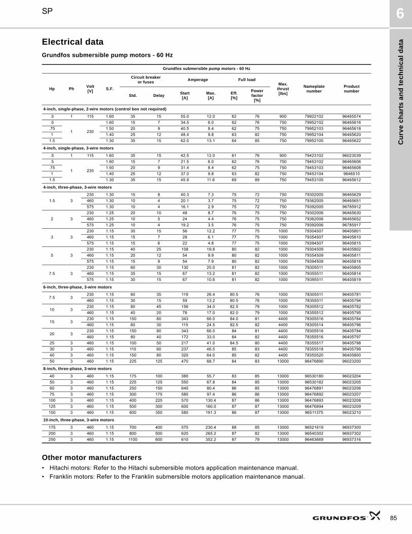
Cu
rve
ch
art
s a
nd
te
ch
nic
al
da
ta
SP 6
Electrical data
Grundfos submersible pump motors - 60 Hz
.
Other motor manufacturers• Hitachi motors: Refer to the Hitachi submersible motors application maintenance manual.
• Franklin motors: Refer to the Franklin submersible motors application maintenance manual.
Grundfos submersible pump motors - 60 Hz
Hp PhVolt[V]
S.F.
Circuit breakeror fuses
Amperage Full loadMax.
thrust[lbs]
Nameplatenumber
Productnumber
Std. DelayStart[A]
Max.[A]
Eff.[%]
Powerfactor
[%]
4-inch, single-phase, 2-wire motors (control box not required)
.5 1 115 1.60 35 15 55.0 12.0 62 76 900 79922102 96465574
.5
1 230
1.60 15 7 34.5 6.0 62 76 750 79952102 96465616
.75 1.50 20 9 40.5 8.4 62 75 750 79952103 96465618
1 1.40 25 12 48.4 9.8 63 82 750 79952104 96465620
1.5 1.30 35 15 62.0 13.1 64 85 750 79952105 96465622
4-inch, single-phase, 3-wire motors
.5 1 115 1.60 35 15 42.5 12.0 61 76 900 79423102 96023039
.5
1 230
1.60 15 7 21.5 6.0 62 76 750 79453102 96465606
.75 1.50 20 9 31.4 8.4 62 75 750 79453103 96465608
1 1.40 25 12 37.0 9.8 63 82 750 79453104 9646510
1.5 1.30 35 15 45.9 11.6 69 89 750 79453105 96465612
4-inch, three-phase, 3-wire motors
1.5 3
230 1.30 15 8 40.3 7.3 75 72 750 79302005 96465629
460 1.30 10 4 20.1 3.7 75 72 750 79362005 96465651
575 1.30 10 4 16.1 2.9 75 72 750 79392005 96785912
2 3
230 1.25 20 10 48 8.7 76 75 750 79302006 96465630
460 1.25 10 5 24 4.4 76 75 750 79362006 96465652
575 1.25 10 4 19.2 3.5 76 75 750 79392006 96785917
3 3
230 1.15 30 15 56 12.2 77 75 1000 79304507 96405801
460 1.15 15 7 28 6.1 77 75 1000 79354507 96405810
575 1.15 15 6 22 4.8 77 75 1000 79394507 96405815
5 3
230 1.15 40 25 108 19.8 80 82 1000 79304509 96405802
460 1.15 20 12 54 9.9 80 82 1000 79354509 96405811
575 1.15 15 9 54 7.9 80 82 1000 79394509 96405816
7.5 3
230 1.15 60 30 130 25.0 81 82 1000 79305511 96405805
460 1.15 35 15 67 13.2 81 82 1000 79355511 96405814
575 1.15 30 15 67 10.6 81 82 1000 79395511 96405819
6-inch, three-phase, 3-wire motors
7.5 3230 1.15 60 35 119 26.4 80.5 76 1000 78305511 96405781
460 1.15 30 15 59 13.2 80.5 76 1000 78355511 96405794
10 3230 1.15 80 45 156 34.0 82.5 79 1000 78305512 96405782
460 1.15 40 20 78 17.0 82.0 79 1000 78355512 96405795
15 3230 1.15 150 80 343 66.0 84.0 81 4400 78305516 96405784
460 1.15 60 30 115 24.5 82.5 82 4400 78305514 96405796
20 3230 1.15 150 80 343 66.0 84 81 4400 78305516 96405784
460 1.15 80 40 172 33.0 84 82 4400 78355516 96405797
25 3 460 1.15 100 50 217 41.0 84.5 80 4400 78355517 96405798
30 3 460 1.15 110 60 237 46.5 85 83 4400 78355518 96405799
40 3 460 1.15 150 80 320 64.0 85 82 4400 78355520 96405800
50 3 460 1.15 225 125 470 68.7 84 83 13000 96476890 96023200
8-inch, three-phase, 3-wire motors
40 3 460 1.15 175 100 380 55.7 83 85 13000 96530180 96023204
50 3 460 1.15 225 125 550 67.8 84 85 13000 96530182 96023205
60 3 460 1.15 250 150 640 80.4 86 85 13000 96476891 96023206
75 3 460 1.15 300 175 580 97.4 86 86 13000 96476892 96023207
100 3 460 1.15 400 225 570 130.4 87 86 13000 96476893 96023208
125 3 460 1.15 500 300 600 160.0 87 87 13000 96476894 96023209
150 3 460 1.15 600 350 580 191.3 86 87 13000 96511375 96023210
10-inch, three-phase, 3-wire motors
175 3 460 1.15 700 400 570 230.4 88 85 13000 96521619 96937300
200 3 460 1.15 800 500 620 265.2 87 82 13000 96540302 96937302
250 3 460 1.15 1100 600 610 352.2 87 79 13000 96463669 96937316
85

Ac
ce
ss
orie
s
SP7
86
7. Accessories
MP 204The MP 204 is an electronic motor protector, designed for the protection of an asynchronous motor or a pump.
The motor protector consists of:
• a cabinet incorporating transformers and electronics
• a control panel with operating buttons and display for reading of data.
The MP 204 operates with two sets of limits:
• a set of warning limits and
• a set of trip limits.
If one or more of the warning limits are exceeded, the motor continues to run, but the warnings will appear in the MP 204 display.
Some values only have a warning limit.
The warning can also be read out by means of the Grundfos R100 remote control.
If one of the trip limits is exceeded, the trip relay will stop the motor. At the same time, the signal relay is operating to indicate that the limit has been exceeded.
ApplicationsThe MP 204 can be used as a stand-alone motor protector.
The MP 204 can be monitored via a Grundfos GENIbus.
The power supply to the MP 204 is in parallel with the supply to the motor. Motor currents up to 120 A are passed directly through the MP 204. The MP 204 protects the motor primarily by measuring the motor current by means of a true RMS measurement. The MP 204 disconnects the contactor if, for example, the current exceeds the preset value.
Secondarily, the motor is protected via temperature measuring by a Tempcon sensor, a Pt100/Pt1000 sensor and a PTC sensor/thermal switch.
The MP 204 is designed for single- and three-phase motors. In single-phase motors, the starting and run capacitors are also measured. Cos is measured in both single- and three-phase systems.
BenefitsThe MP 204 offers these benefits:
• Suitable for both single- and three-phase motors
• Dry-running protection
• Overload protection
• Very high accuracy
• Made for submersible pumps.
Many monitoring options
The MP 204 monitors the following parameters:
• Insulation resistance before start-up
• Temperature (Tempcon, Pt sensor and PTC/thermal switch)
• Overload/underload
• Overvoltage/undervoltage
• Phase sequence
• Phase failure
• Power factor
• Power consumption
• Harmonic distortion
• Operating hours and number of starts.
Fig. 21 MP 204
Fig. 22 Single-turn transformers
Product numbers
TM
03
147
1 2
205
TM
03
203
3 3
505
ProductProduct number
MP 204 96079927
R100 625333
Five sizes of single-turn transformers, 120-999 A.Note: Monitoring of motor temperature is not possible when single-turn transformers are used.

Ac
ce
ss
ori
es
SP 7
Functions
• Phase-sequence monitoring
• Indication of current or temperature (user selection)
• Indication of temperature in °F or °C (user selection)
• 4-digit, 7-segment display
• Setting and status reading with the R100
• Setting and status reading via the GENIbus.
Tripping conditions
• Overload
• Underload (dry running)
• Temperature (Tempcon sensor, PTC/thermal switch and Pt sensor)
• Phase failure
• Phase sequence
• Overvoltage
• Undervoltage
• Power factor (cos )
• Current unbalance.
Warnings
• Overload
• Underload
• Temperature (Tempcon and Pt sensor)
• Overvoltage
• Undervoltage
• Power factor (cos )Note: In connection with single- and three-phase connection.
• Run capacitor (single-phase operation)
• Starting capacitor (single-phase operation)
• Loss of communication in network
• Harmonic distortion.
Learning function
• Phase sequence (three-phase operation)
• Run capacitor (single-phase operation)
• Starting capacitor (single-phase operation)
• Identification and measurement of Pt100/Pt1000 sensor circuit.
External current transformers
When fitted with external current transformers, the MP 204 unit can handle currents from 120 to 999 A. Grundfos can supply approved current transformers from stock (200/5A, 300/5A, 500/5A, 750/5A, 1000/5A).
Remote control R100
The R100 remote control from Grundfos allows for wireless infrared remote control of your MP 204 unit.
With the R100, you get access to a full range of options such as factory setting adjustment, service and fault finding.
Ready for bus communication
The MP 204 allows for monitoring and communication via GENIbus — a Grundfos-designed bus for exchange of pump data, alarms, status information, and setpoints. This enables users to connect the MP 204 to, for instance, SCADA systems.
87

Ac
ce
ss
orie
s
SP7
88
Technical data - MP 204
Enclosure class IP 20
Ambient temperature –4 °F to +140 °F (–20 °C to +60 °C)
Relative air humidity 99%
Voltage range 100-480 VAC
Current range 3-999 A
Frequency 50 to 60 Hz
IEC trip class 1-45
Special Grundfos trip class 0.1 to 30 s
Voltage variation –25 %/+15 % of nominal voltage
Approvals EN 60947, EN 60335, UL/CSA 508
Marking CE, cUL, C-tick
Consumption Max. 5 W
Plastic type Black PC / ABS
Measuring range Accuracy Resolution
Current without external current transformers 3-120 A ±1 % 0.1 A
Current with external current transformers 120-999 A ±1 % 1 A
Phase-to-phase voltage 80-610 VAC ±1 % 1 V
Frequency 47-63 Hz ±1 % 0.5 Hz
Power 0-1 MW ±2 % 1 W
Power factor 0-0.99 ±2 % 0.01
Energy consumption 0-4x10⁹ kWh ±5 % 1 kWh
IO 112 Description Product number
The IO 112 is a measuring module and a 1-channel protection unit for use in con-nection with the MP 204 motor protection unit. The module can be used for pro-tection of pump against other factors than the electrical conditions, for instance dry-running. It can also be used as a stand-alone protection module.
The IO 112 interface has three inputs for measured values one potentiometer for setting of limits indicator lights indicating the• measured value of the input• value of the limit set• alarm source• pump status.
Electrical data:• Supply voltage: 24 VAC ±10% 50/60 Hz or 24 VDC ±10% • Supply current: Min. 2.4 A; max. 8 A• Power consumption:Max. 5 WAmbient temperature: –13 °F to+149 °F (–25 °C to +65 °C)• Enclosure class: IP 20
96651601

Ac
ce
ss
ori
es
SP 7
Control functionsThis table describes the protection provided by MP 204.
Control parameters Function Problem Advantages
Temperature
MS
The motor temperature is measured by means of the built-in Tempcon temperature transmitter and a signal is sent to MP 204 via the phase leads. In MP 204 the measured temperature is compared with the factory-set value (167 °F (75 °C)).
MMS
The motor temperature is measured by means of the Pt100. The signal is sent to the MP 204 where the measured temperature is compared with the factory-set value. Temperature protection requires a submersible motor with a Pt100.
The motor temperature must be monitored during frequency converter operation.
Overload, frequent starts/stops, operation against blocked discharge pipe, insufficient flow velocity past the motor.
Longer motor life, safe operating conditions, service indication.
Overvoltage/undervoltage
If the set trip value is exceeded, the motor will stop.
The installation is close to a transformer. The mains do not absorb load variations.
Important installation parameter, possibility of improving operating conditions.
Overload
The motor power input is measured on each of the three phases. The registered power input is an average of these three values. If the factory-set value is exceeded, the motor will stop.
Incorrect sizing of pump/motor, voltage supply failure, defective cable, blocking, wear or corrosion.
Longer pump life, safe operating conditions, service indication.
Underload (dry running)
The motor power input is measured on each of the three phases. The registered power input is an average of these three values. If the average value is lower than the factory-set value, the motor will stop.
Pump exposed to dry running or underload, for example caused by wear.
Traditional dry-running protection is no longer necessary, no extra cables.
Current unbalance The power input of the motor is measured on each of the three phases.
Mains load is uneven, incipient motor defect, phase voltages diverging.
Motor protection against overload, service indication.
Phase sequence
MP 204 and motor are installed so that the phase sequence corresponds to correct direction of rotation. MP 204 monitors changes in the phase sequence.
Two phases are wrongly connected.
Ensures correct pump performance.
Phase failureMP 204 checks the phases connected, phase failure will cause an alarm.
Phase failure Indication of phase failure, and alarm.
89

Ac
ce
ss
orie
s
SP7
90
R100 menus
0. GENERAL
See the operating instructions for the R100.
1. OPERATION
• Operating mode
• Actual trip
• Actual warning 1
• Actual warning 2
• Alarm log 1
• Alarm log 2
• Alarm log 3
• Alarm log 4
• Alarm log 5.
2. STATUS
Display of
• Supply overview
• Average current
• Average voltage
• Tempcon sensor
• Pt100/Pt1000 sensor
• Power input and energy consumption (described in the following)
• Energy trip counter
• Phase sequence
• Current unbalance
• Operating hours and number of starts
• Trip counter of hours and starts
• Starting capacitor
• Run capacitor
• Insulation resistance
• Cos
• Harmonic distortion.
3. LIMITS
Display and setting of warning and trip limits.
• Tempcon sensor
• Pt sensor
• Tripping current
• Current warning
• Nominal voltage
• Voltage limits
• Current unbalance
• Starting capacitor
• Run capacitor
• Insulation resistance
• Cos trip
• Cos warning.
4. INSTALLATION
Setting and display of
• Supply mains
• Trip class (described in the following)
• Trip delay
• External current transformers
• Power-on delay
• Restarting (described in the following)
• Automatic restarting (described in the following)
• Tempcon sensor
• Pt sensor
• Insulation resistance measurement
• PTC/thermal switch
• Resetting of trip counters
• Service interval
• Number of automatic restarts
• Units/display
• MP 204 display
• GENIbus ID number
• Learning function.
Power input and energy consumption
Actual input power and motor energy consumption.
The energy consumption is an accumulated value which cannot be reset.
The power is calculated like this:
Uaverage
UL1 L2– UL2 L3– UL3 L1–+ +
3-------------------------------------------------------------------------------------- V =
Iaverage
IL1 IL2 IL3+ +
3--------------------------------------- A =
cos average
cos L1 cos L2 cos L3+ +
3---------------------------------------------------------------------------- - =
P Uaverage Iaverage 3 cos average W =

Ac
ce
ss
ori
es
SP 7
Trip class
Line 1: Select IEC trip class (1 to 45).
If manual indication of trip delay in the case of overload is required, select trip class "P".
Factory setting:
• Cls (trip class): P.
Line 2: Select trip delay.
Factory setting:
• Dly (trip delay): 10 s.
Restarting
Set whether restarting after tripping is to be
• Automatic (factory setting)
• Manual.
Setting of time, see section "Automatic restarting".
Automatic restarting
Set the time after which the MP 204 is to attempt automatic restarting of motor after cut-out.
The time runs from the moment when the value which triggered the fault has returned to normal.
Factory setting:
• 300 s.
91

Ac
ce
ss
orie
s
SP7
92
G100 gateway for communication with Grundfos productsThe G100 offers a wide selection of options for integration of Grundfos products provided with GENIbus interface into main control and monitoring systems.
The G100 enables a pump installation to meet future demands for optimum pump operation in terms of reliability, operating costs, centralization and automation.
Fig. 23 G100
Fig. 24 Examples of G100 applications
GR
594
0T
M03
92
24 3
607
Port 1
MainNetwork
Connection
POWERPOWER MNCPOWER GENIGENI TxDGENI RxDFAULT
DCDRTSTxD1RxD1TxD2RxD2
Port 2
Genibus DI Service
MP 204 Hydro IO 351
Pump SQESensor
MP 204 IO 351
SensorsPump
MP 204
Pump
Wastewater
Industry
RS-232 Serviceport for PC
PR
OF
IBU
S-D
P
Dire
ct
PLCModemRadio
Radio
4 digital inputs
Water supply
GE
NIb
us
MP 204 CU 300 DMEE-
pump
Pump SQE
Water treatment
E-pump
HydroMPC
UPE
Heating
TPE UPS
MGE
CU 300 Multi-E
Multi-EIO 351
SMS
Central management system
Main network
MAGNA
IO 351
SensorsSensors
MPC
MP 204
Pump
IO112

Ac
ce
ss
ori
es
SP 7
Product description
The G100 Gateway enables communication of operating data, such as measured values and setpoints, between Grundfos products with GENIbus interface and a main network for control and monitoring.
As indicated in the illustration on page 92, the G100 is suitable for use in applications such as water supply, water treatment, wastewater, building automation and industry.
Common to above applications is that downtime is usually costly, and extra investments are therefore often made to achieve maximum reliability by monitoring selected operating variables.
The day-to-day operation, such as starting and stopping of pumps and changing of setpoints, can also be effected from the main system by communication with the G100. In addition, the G100 can be set up to send event-controlled status indications such as alarms via the SMS to mobile phones, and to make automatic alarm call-backs to a central management system.
Data logging
Besides the possibility of data communication, the G100 offers logging of up to 350,000 time-stamped data. The logged data can be transmitted to the main system or a PC for further analysis in a spreadsheet or similar program.
For the data logging, the "PC Tool G100 Data Log" software tool is used. The tool is part of the PC Tool G100 package, which is supplied with the G100.
Other features
• Four digital inputs.
• Stop of all pumps in case of failing communication with the management system (optional).
• Access code for modem communication (optional).
• Alarm log.
Installation
Installation of the G100 is effected by the system integrator. The G100 is connected to the GENIbus as well as to the main network. All units on the GENIbus can thus be controlled from a central management system on the main network.
The "G100 Support Files" CD-ROM supplied with the G100 contains examples of programs to be used when the G100 is connected to the various main network systems. Included is also a description of the data points available in Grundfos products with GENIbus interface.
The "PC Tool G100" software tool included can be used for the installation and use of G100.
Fig. 25 Dimensional sketch
Technical data
Overview of protocols
Other possible connections
Accessories
• PC Tool G100 package (supplied with the product)
• G100 Support Files CD-ROM (supplied with product)
Product numbers
* CD-ROM with G100 Support Files included.
TM
01
062
1 1
102
Main system Software protocol
PROFIBUS-DP DP
Radio Satt Control COMLI/Modbus
Modem Satt Control COMLI/Modbus
PLC Satt Control COMLI/Modbus
GSM mobile phone SMS, UCP
GENIbus RS-485: Connection of up to 32 units.
Service port RS-232: For direct connection to a PC or via radio modem.
Digital inputs: 4.
Voltage supply: 1 x 110-240 V, 50/60 Hz.
Ambient temperature: In operation:–4 °F to +140 °F(–20 °C to +60 °C).
Enclosure class: IP 20.
Weight: 1.8 kg.
ProductProduct number
G100 with Profibus-DP expansion board* 96411135
G100 with Radio/Modem/PLC expansion board* 96411136
G100 Basic Version* 96411137
PC Tool G100 package 96415783
73 mm 165 mm
227
mm
Port 1
Main
Network
Connection
POWER
POWER MNC
POWER GENI
GENI TxD
GENI RxD
FAULT
DCD
RTS
TxD1
RxD1
TxD2
RxD2
Port 2
Genibus DI Service
93

Ac
ce
ss
orie
s
SP7
94
Connecting piecesThe tables below show the range of connecting pieces for connection of thread-to-flange and thread-to-thread.
Thread-to- thread
Fig. 26 Dimensional sketch and photo of connecting piece thread-to-thread
TM
01
239
7 1
698
- G
rA2
555
L
B A
Type Connecting piece
DimensionsProduct number
Thread-to-threadL
[in (mm)]A B304
stainless steel316
stainless steel
385S475S
NPT 5 NPT 4 NPT 5 NPT 4 4.76 (121) 190064 190586
NPT 5 NPT 6 NPT 5 NPT 6 5.91 (150) 190070 190592
625S800S
1100SNPT 6 NPT 5 NPT 6 NPT 5 5.91 (150) 200135 200645

Ac
ce
ss
ori
es
SP 7
Zinc anodes
Application
Cathodic protection by means of zinc can be used for corrosion protection of SP pumps in chloride-containing liquids such as brackish water and seawater.
Sacrificial anodes are placed on the outside of the pump and motor as protection against corrosion.
The number of anodes required depends on the pump and motor in question.
Please contact Grundfos for further details.
Liquid temperatures
• Seawater:Up to 95 °F (35 °C).
• Brackish water (min. 1500 ppm (g/m3) chloride):Up to 95 °F (35 °C).
Anode life
The zinc anodes have a life of one to four years, depending on operating conditions (temperature, flow and chloride content).
Product numbers of zinc anodes
Zinc anodes for pumps
Product number
Used for pump type
SP
5S
to
75
S
85
S
15
0S
23
0S
30
0S
38
5S
47
5S
62
5S
80
0S
110
0S
96421444 - - - - - - - - -
96421445 - - - - - -
96421447 - - - - - - - -
96421448 - - - - - - - - -
96421449 - - - - - - - - -
96421450 - - - - - - -
Zinc anodes for motors
4" motors 6" motors 8" motors 10" motors
96421444 96421446 96421450 96564808
95

Ac
ce
ss
orie
s
SP7
96
SA-SPM 5 control boxes
Application
SA-SPM 5 control boxes are used as starting units for single-phase, 3-wire motors, types MS 402B with power input lower than or equal to 1.5 hp (1.1 kW).
SA-SPM 5 is available in two versions, standard and DeLuxe. The standard version incorporates a motor -protective circuit breaker and thus protects the motor against overload. The DeLuxe version is identical to the standard version with the following addition a motor contactor is included for connection and disconnection of the power supply.
Technical data
Enclosure class: IP 42.
Ambient temperature: –4 °F to +140 °F(–20 °C to +60 °C).
Relative humidity: Maximum 95 %, normal non-aggressive atmosphere.
Fig. 27 SA-SPM 5 control box
Product numbers
TM
03
81
50 0
607
Product
Description
Product number
1 x
22
0-2
30
V
1.5
hp
2.0
hp
3.0
hp
5.0
hp
SA-SPM 5 (Standard version) - - - 91126212
SA-SPM 5 (DeLuxe version) - - - 91126213
SA-SPM 5 (Standard version) - - - 91126214
SA-SPM 5 (DeLuxe version) - - - 91126215
SA-SPM 5 (Standard version) - - - 91126216
SA-SPM 5 (DeLuxe version) - - - 91126217
SA-SPM 5 (Standard version) - - - 91126218
SA-SPM 5 (DeLuxe version) - - - 91126219

Ac
ce
ss
ori
es
SP 7
Pt100The Pt100 sensor offers these features:
• Continuous monitoring of the motor temperature
• Protection against too high motor temperature.
Protecting the motor against too high motor temperature is the simplest and cheapest way of avoiding that motor lifetime is reduced. Pt100 ensures that operating conditions are not exceeded and indicates when it is time for service of the motor.
Monitoring and protection by means of Pt100 require the following parts:
• Pt100 sensor
• Relay, type PR 5714
• Cable.
The PR 5714 relay is fitted with a Pt100 module. For both relays the following temperature limits are preset on delivery:
• +60 °C (+140 °F) warning limit
• +75 °C (+167 °F) stop limit.
Technical data
Relay type
PR 5714
Enclosure class IP 65 (mounted in a control panel)
Ambient temperature –4 °F to +140 °F (–20 °C to +60 °C)
Relative humidity 95 % (condensating)
Voltage variation• 1 x 24-230 VAC ±10 %, 50 - 60 Hz.• 24-250 VDC ±20 %.
Approvals UL, DNV
Mark CE
Pt100 sensor with/without PR 5714 relay and cableCable length
[ft (m)]PR 5714
Product number
MS6MMS 6000,MMS 8000
MMS 10000,MMS 12000
65.6 (20) Yes 96408953 96494596 96437287
131.2 (40) Yes 96408681 96494597 96437288
196.9 (60) Yes 96408954 96494598 96437289
262.5 (80) Yes 96408955 96494599 96437290
328.1 (100) Yes 96408956 96494610 96437291
65.6 (20) No 96658626 96658629 96658633
131.2 (40) No 96658627 96658630 96658634
196.9 (60) No 96658628 96658631 96658635
262.5 (80) No 96658637 96658632 96658636
328.1 (100) No 96658638 96658639 96658640
PR 5714 relay Voltage Product number
24-230 VAC, 50/60 Hz / 24-250 VDC 96621274
Pt100 sensor including cableCable length
[ft (m)]
Product number
MS6, MMS 6000,MMS 8000
MMS 10000MMS 12000
65.6 (20) 96408957 96437784
131.2 (40) 96408684 96437785
196.9 (60) 96408958 96437786
262.5 (80) 96408959 96437787
328.1 (100) 96408960 96437788
Staybolts for Pt100 Description Product number
Bolt KIT for Pt100 (for MS6) 96611899
97

En
erg
y c
on
su
mp
tion
SP8
98
8. Energy consumption
Energy consumption of submersible pumps The percentage distribution of service life costs of a submersible pump for water supply is:
5 % initial costs (pump)85 % operating costs / energy consumption10 % maintenance costs.
It is obvious that the highest savings can be achieved within energy consumption!
The annual energy consumption, E, of a submersible pump can be calculated as follows:
E = c x h x P1 (EURO)
c = specific energy price (EURO/kWh)
h = operating hours/year (hours)
P1 = power input of the submersible pump (kW).
Example: Calculation of the annual energy consumption of the submersible pump, type 625S-3.
625S-3 with MS 8000, 45 kW, 3 x 460 V, 60 Hz.
Duty point:
Flow rate: Q = 120 m3/h
Total head: H = 102 m
Specific energy price:c = EURO 0.1/kWh (consisting of day and night rate)
Operating hours/year: h = 3200.
Q = m3/h
H = m
Density = kg/dm3 (assumed 1)
367 = conversion factor
motor = (example 84.5 %, in equation 0.845)
pump = (not to be confused with the stage efficiency curve).
By showing the P2/Q curve we make it easier for you to calculate the energy consumption.
P2 = 26 kW (power requirement of 625S-3 pump at 20 m3/h, from curve P2 / Q on page 72).
Calculation of motor efficiency at duty point
As standard the SP 625S-3 is equipped with a 45 kW MS6 motor.
At duty point (Q = 120 m3/h) the pump requires 44 kW, thus:
a motor load of 87 % (44 kW / 45 kW) and a power reserve of 2 %.
From the table on page 72 the motor efficiency can be read as:
84.6 % at a load of 75 %. ( 75 %)85.6 % at a load of 100 %. ( 100 %)The interpolated value in this example is motor = 85.1 %, motor = 0.851.
E = 0.1 EURO/kWh x 3200 h x 51.7 kW.The annual energy costs amount to EURO 16544.
The pay-off time, A, (months) is calculated as follows:
Cable sizing
In order to obtain an economical duty of the pump the voltage drop should be low.
Today large water works already size cables for a maximum voltage drop of 1 %).
The hydraulic resistance in the discharge pipe should be as low as possible.P1
Q H 367 pump motor---------------------------------------------------------------in kW=
P1
P2
motor---------------------=
P144
0.851--------------- 51.7 kW= =
APurchase price of energy eff iciency pump–
Energy savings/year----------------------------------------------------------------------------------------------------------------------------------- 12=
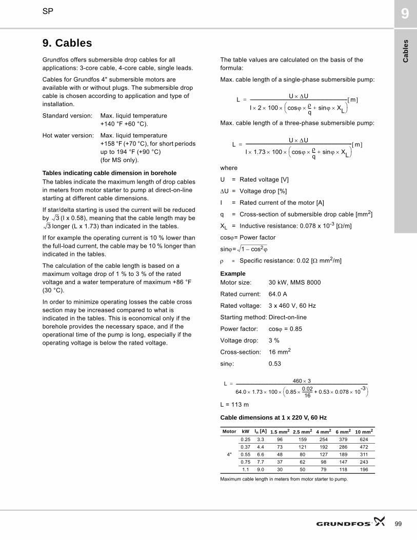
Ca
ble
s
SP 9
9. Cables
Grundfos offers submersible drop cables for all applications: 3-core cable, 4-core cable, single leads.
Cables for Grundfos 4" submersible motors are available with or without plugs. The submersible drop cable is chosen according to application and type of installation.
Standard version: Max. liquid temperature+140 °F +60 °C).
Hot water version: Max. liquid temperature+158 °F (+70 °C), for short periods up to 194 °F (+90 °C)(for MS only).
Tables indicating cable dimension in borehole
The tables indicate the maximum length of drop cables in meters from motor starter to pump at direct-on-line starting at different cable dimensions.
If star/delta starting is used the current will be reduced by (I x 0.58), meaning that the cable length may be
longer (L x 1.73) than indicated in the tables.
If for example the operating current is 10 % lower than the full-load current, the cable may be 10 % longer than indicated in the tables.
The calculation of the cable length is based on a maximum voltage drop of 1 % to 3 % of the rated voltage and a water temperature of maximum +86 °F (30 °C).
In order to minimize operating losses the cable cross section may be increased compared to what is indicated in the tables. This is economical only if the borehole provides the necessary space, and if the operational time of the pump is long, especially if the operating voltage is below the rated voltage.
The table values are calculated on the basis of the formula:
Max. cable length of a single-phase submersible pump:
Max. cable length of a three-phase submersible pump:
where
U = Rated voltage [V]
U = Voltage drop [%]
I = Rated current of the motor [A]
q = Cross-section of submersible drop cable [mm2]
XL = Inductive resistance: 0.078 x 10⁻³ [/m]
cos= Power factor
sin=
= Specific resistance: 0.02 [ mm2/m]
Example
Motor size: 30 kW, MMS 8000
Rated current: 64.0 A
Rated voltage: 3 x 460 V, 60 Hz
Starting method: Direct-on-line
Power factor: cos = 0.85
Voltage drop: 3 %
Cross-section: 16 mm2
sin: 0.53
L = 113 m
Cable dimensions at 1 x 220 V, 60 Hz
Maximum cable length in meters from motor starter to pump.
33
Motor kW In [A] 1.5 mm2 2.5 mm2 4 mm2 6 mm2 10 mm2
4"
0.25 3.3 96 159 254 379 624
0.37 4.4 73 121 192 286 472
0.55 6.6 48 80 127 189 311
0.75 7.7 37 62 98 147 243
1.1 9.0 30 50 79 118 196
LU U
I 2 100 cos q--- sin XL+
----------------------------------------------------------------------------------------------- m =
LU U
I 1.73 100 cos q--- sin XL+
-------------------------------------------------------------------------------------------------------- m =
1 cos2–
L 460 3
64.0 1.73 100 0.850.0216
----------- 0.53 0.078 10-3
+
-------------------------------------------------------------------------------------------------------------------------------------------------=
99

Ca
ble
s
SP9
100
Cable sizing chart
1 phase, 60 Hz
Motor rating Copper wire size
Volts Hp
14 12 10 8 6 4 2 0 00 000 0000 250 300
Maximum motor cable length (motor service to entrance) [ft/m]
115
0.33 130 (40) 210 (64) 340 (104) 540 (165) 840 (256) 1300 (396) 1960 (597) 2910 (887)
0.5 100 (30) 160 (49) 250 (76) 390 (119) 620 (189) 960 (293) 1460 (445) 2160 (658)
0.33 550 (168) 880 (268) 1390 (424) 2190 (668) 3400 (1036) 5250 (1600) 7960 (2426)
0.5 400 (122) 650 (198) 1020 (311) 1610 (491) 2510 (765) 3880 (1183) 5880 (1792)
0.75 300 (91) 480 (146) 760 (232) 1200 (366) 1870 (570) 2890 (881) 4370 (1332) 6470 (1972)
1 250 (76) 400 (122) 630 (192) 990 (302) 1540 (469) 2380 (725) 3610 (1100) 5360 (1634) 6520 (1987)
1.5 190 (58) 310 (94) 480 (146) 770 (235) 1200 (366) 1870 (570) 2850 (869) 4280 (1305) 5240 (1597)
2 150 (46) 250 (76) 390 (119) 620 (189) 970 (296) 1530 (466) 2360 (719) 3620 (1103) 4480 (1366)
3 120 (37) 190 (58) 300 (91) 470 (143) 750 (229) 1190 (363) 1850 (564) 2890 (881) 3610 (1100)
5 180 (55) 280 (85) 450 (137) 710 (216) 1110 (338) 1740 (530) 2170 (661)
7.5 200 (61) 310 (94) 490 (149) 750 (229) 1140 (347) 1410 (430)
10 250 (76) 390 (119) 600 (183) 930 (283) 1160 (354)
3 phase, 60 Hz
Motor rating Copper wire size
Volts Hp
14 12 10 8 6 4 2 0 00 000 0000 250 300
Maximum motor cable length (motor service to entrance) [ft/m]
208
1.5 310 (94) 500 (152) 790 (241) 1260 (384)
2 240 (73) 390 (119) 610 (186) 970 (296) 1520 (463)
3 180 (55) 290 (88) 470 (143) 740 (226) 1160 (354) 1810 (552)
5 170 (52) 280 (85) 440 (134) 690 (210) 1080 (329) 1660 (506)
7.5 200 (61) 310 (94) 490 (149) 770 (235) 1180 (360) 1770 (539)
10 230 (70) 370 (113) 570 (174) 880 (268) 1330 (405) 1640 (500)
15 250 (76) 390 (119) 600 (183) 910 (277) 1110 (338) 1340 (408)
20 300 (91) 460 (140) 700 (213) 860 (262) 1050 (320) 1270 (387)
25 370 (113) 570 (174) 700 (213) 840 (256) 1030 (314) 1170 (357)
30 310 (94) 470 (143) 580 (177) 700 (213) 850 (259) 970 (296) 1110 (338)
230
1.5 360 (110) 580 (177) 920 (280) 1450 (442)
2 280 (85) 450 (137) 700 (213) 1110 (338) 1740 (530)
3 210 (64) 340 (104) 540 (165) 860 (262) 1340 (408) 2080 (634)
5 200 (61) 320 (98) 510 (155) 800 (244) 1240 (378) 1900 (579)
7.5 230 (70) 360 (110) 570 (174) 890 (271) 1350 (411) 2030 (619)
10 270 (82) 420 (128) 660 (201) 1010 (308) 1520 (463) 1870 (570)
15 290 (88) 450 (137) 690 (210) 1040 (317) 1280 (390) 1540 (469)
20 350 (107) 530 (162) 810 (247) 990 (302) 1200 (366) 1450 (442)
25 280 (85) 430 (131) 650 (198) 800 (244) 970 (296) 1170 (357) 1340 (408)
30 350 (107) 540 (165) 660 (201) 800 (244) 970 (296) 1110 (338) 1270 (387)
460
1.5 1700 (518)
2 1300 (396) 2070 (631)
3 1000 (305) 1600 (488) 2520 (768)
5 590 (180) 950 (290) 1500 (457) 2360 (719)
7.5 420 (128) 680 (207) 1070 (326) 1690 (515) 2640 (805)
10 310 (94) 500 (152) 790 (241) 1250 (381) 1960 (597) 3050 (930)
15 540 (165) 850 (259) 1340 (408) 2090 (637) 3200 (975)
20 410 (125) 650 (198) 1030 (314) 1610 (491) 2470 (753) 3730 (1137)
25 530 (162) 830 (253) 1300 (396) 1990 (607) 3010 (917) 3700 (1128)
30 430 (131) 680 (207) 1070 (326) 1640 (500) 2490 (759) 3060 (933) 3700 (1128)
40 790 (241) 1210 (369) 1830 (558) 2250 (686) 2710 (826) 3290 (1003)
50 640 (195) 980 (299) 1480 (451) 1810 (552) 2190 (668) 2650 (808) 3010 (917)
60 830 (253) 1250 (381) 1540 (469) 1850 (564) 2240 (683) 2540 (774) 2890 (881)
75 1030 (314) 1260 (384) 1520 (463) 1850 (564) 2100 (640) 2400 (732)
100 940 (287) 1130 (344) 1380 (421) 1560 (475) 1790 (546)
125 1080 (329) 1220 (372) 1390 (424)
150 1050 (320) 1190 (363)
200 1080 (329) 1300 (396)
250 1080 (329)

Ca
ble
s
SP 9
CAUTION: Use of wire size smaller than listed will void warranty.Notes:1. If aluminum conductor is used, multiply lengths by 0.5 Maximum allowable length of aluminum is considerably shorter than copper wire of same size.2. The portion of the total cable which is between the service entrance and a 3ø motor starter should not exceed 25% of the total maximum length to assure reliable starter operation.Single-phase control boxes may be connected at any point of the total cable length.3. Cables #14 to #0000 are AWG sizes, and 250 to 300 are MCM sizes.
3 phase, 60 Hz
Motor rating Copper wire size
Volts Hp
14 12 10 8 6 4 2 0 00 000 0000 250 300
Maximum motor cable length (motor service to entrance) [ft/m]
575
1.5 2620 (799)
2 2030 (619)
3 1580 (482) 2530 (771)
5 920 (280) 1480 (451) 2330 (710)
7.5 660 (201) 1060 (323) 1680 (512) 2650 (808)
10 490 (149) 780 (238) 1240 (378) 1950 (594)
15 530 (162) 850 (259) 1340 (408) 2090 (637)
20 650 (198) 1030 (314) 1610 (491) 2520 (768)
25 520 (158) 830 (253) 1300 (396) 2030 (619) 3110 (948)
30 680 (207) 1070 (326) 1670 (509) 2560 (780) 3880 (1183)
40 790 (241) 1240 (378) 1900 (579) 2860 (872) 3510 (1070)
50 1000 (305) 1540 (469) 2310 (704) 2840 (866) 3420 (1042)
60 850 (259) 1300 (396) 1960 (597) 2400 (732) 2890 (881) 3500 (1067)
75 1060 (323) 1600 (488) 1970 (600) 2380 (725) 2890 (881) 3290 (1003)
101

Fric
tion
los
s ta
ble
s
SP10
102
10. Friction loss tablesFriction loss table - SCH 40 steel pipe
U.S. gpm U.S. gph
.5" .75" 1" 1.25" 1.5" 2" 2.5" 3" 4"
ID 0.622" ID 0.824" ID 1.049" ID 1.380" ID 1.610" ID 2.067" ID 2.469" ID 3.068" ID 4.026"
Friction loss in feet of head per 100 feet of pipe
2 120 4.8
3 180 10.0 2.5
4 240 17.1 4.2
5 300 25.8 6.3 1.9
6 360 36.5 8.9 2.7
7 420 48.7 11.8 3.6
8 480 62.7 15.0 4.5
9 540 78.3 18.8 5.7
10 600 95.9 23.0 6.9
12 720 32.6 9.6 2.5 1.2
14 840 43.5 12.8 3.3 1.5
16 960 56.3 16.5 4.2 2.0
20 1,200 86.1 25.1 6.3 2.9
25 1,500 38.7 9.6 4.5 1.3
30 1,800 54.6 13.6 6.3 1.8
35 2,100 73.3 18.2 8.4 2.4
40 2,400 95.0 23.5 10.8 3.1 1.3
45 2,700 29.4 13.5 3.9 1.6
50 3,000 36.0 16.4 4.7 1.9
60 3,600 51.0 23.2 6.6 2.7
70 4,200 68.8 31.3 8.9 3.6 1.2
80 4,800 89.2 40.5 11.4 4.6 1.6
90 5,400 51.0 14.2 5.8 2.0
100 6,000 62.2 17.4 7.1 2.4
120 7,200 24.7 10.1 3.4
140 8,400 33.2 13.5 4.5 1.2
160 9,600 43.0 17.5 5.8 1.5
200 12,000 66.3 27.0 8.9 2.3
260 15,600 45.0 14.8 3.7
300 18,000 59.6 19.5 4.9

Fri
cti
on
lo
ss
ta
ble
s
SP 10
Notes:Based on Schedule 40 steel and plastic fittings1Friction loss figures are for screwed valves and are based on equivalent lengths of steel pipe.
Friction loss table - SCH 40 PVC pipe
U.S. gpm U.S. gph
.5" .75" 1" 1.25" 1.5" 2" 2.5" 3" 4"
ID 0.622" ID 0.824" ID 1.049" ID 1.380" ID 1.610" ID 2.067" ID 2.469" ID 3.068" ID 4.026"
Friction loss in feet of head per 100 feet of pipe
2 120 4.1
3 180 8.7 2.2
4 240 14.8 3.7
5 300 22.2 5.7 1.8
6 360 31.2 8.0 2.5
7 420 41.5 10.6 3.3
8 480 53.0 13.5 4.2
9 540 66.0 16.8 5.2
10 600 80.5 20.4 6.3 1.7
12 720 28.6 8.9 2.3 1.1
14 840 38.0 11.8 3.1 1.4
16 960 48.6 15.1 4.0 1.9
20 1,200 60.5 22.8 6.0 2.8
25 1,500 38.7 9.1 4.3 1.3
30 1,800 12.7 6.0 1.8
35 2,100 16.9 8.0 2.4
40 2,400 21.6 10.2 3.0 1.1
45 2,700 28.0 12.5 3.8 1.4
50 3,000 15.4 4.6 1.7
60 3,600 21.6 6.4 2.3
70 4,200 28.7 8.5 3.0 1.2
80 4,800 36.8 10.9 3.8 1.4
90 5,400 45.7 13.6 4.8 1.8
100 6,000 56.6 16.5 5.7 2.2
120 7,200 23.1 8.0 3.0
140 8,400 30.6 10.5 4.0 1.1
160 9,600 39.3 13.4 5.0 1.4
200 12,000 66.3 20.1 7.6 2.1
260 15,600 32.4 12.2 3.4
300 18,000 42.1 15.8 4.4
Type of fittingand application
Pipe andfitting
Nominal size of fitting and pipe
1/2" 3/4" 1" 1.25" 1.5" 2" 2.5"
Friction loss in equivalent length of straight pipe in feet
Insert coupling Plastic 3 3 3 3 3 3 3
Threaded adapter(plastic to thread)
Plastic 3 3 3 3 3 3 3
90° standard elbowSteel 2 2 3 4 4 5 6
Plastic 2 2 3 4 4 5 6
Standard tee(flow through run)
Steel 1 2 2 3 3 4 4
Plastic 1 2 2 3 3 4 4
Standard tee(flow through side)
Steel 4 5 6 7 8 11 13
Plastic 4 5 6 7 8 11 13
Gate valve1 Steel 1 1 1 1 2 2 2
Swing check valve1 Steel 5 7 9 12 13 17 21
103

Fu
rthe
r pro
du
ct d
oc
um
en
tatio
n
SP11
104
11. Further product documentation
WebCAPSWebCAPS is a Web-based Computer Aided Product Selection program available on www.grundfos.com.
WebCAPS contains detailed information on more than 185,000 Grundfos products in more than 20 languages.
In WebCAPS, all information is divided into 6 sections:
• Catalog
• Literature
• Service
• Sizing
• Replacement
• CAD drawings.
Catalog
This section is based on fields of application and pump types, and contains • technical data• curves (QH, Eta, P1, P2, etc) which can be adapted to the
density and viscosity of the pumped liquid and show the num-ber of pumps in operation
• product photos• dimensional drawings• wiring diagrams• quotation texts, etc.
Literature
In this section you can access all the latest documents of a given pump, such as• product guides• installation and operating instructions• service documentation, such as Service kit catalog
and Service kit instructions• quick guides• product brochures, etc.
Service
This section contains an easy-to-use interactive service catalog. Here you can find and identify service parts of both existing anddiscontinued Grundfos pumps.Furthermore, this section contains service videos showing you how to replace service parts.

Fu
rth
er
pro
du
ct
do
cu
me
nta
tio
n
SP 11
WinCAPS
Fig. 28 WinCAPS CD-ROM
WinCAPS is a Windows-based Computer Aided Product Selection program containing detailed infor-mation on more than 185,000 Grundfos products in more than 20 languages.
The program contains the same features and functions as WebCAPS, but is an ideal solution if no Internet connection is available.
WinCAPS is available on CD-ROM and updated once a year.
Sizing
This section is based on different fields of application and instal-lation examples, and gives easy step-by-step instructions in how to• select the most suitable and efficient pump for your installation• carry out advanced calculations based on energy consump-
tion, payback periods, load profiles, life cycle costs, etc.• analyse your selected pump via the built-in life cycle cost tool• determine the flow velocity in wastewater applications, etc.
Replacement
In this section you find a guide to selecting and comparing replacement data of an installed pump in order to replace the pump with a more efficient Grundfos pump. The section contains replacement data of a wide range of pumps produced by other manufacturers than Grundfos.
Based on an easy step-by-step guide, you can compare Grund-fos pumps with the one you have installed on your site. When you have specified the installed pump, the guide will suggest a number of Grundfos pumps which can improve both comfort and efficiency.
CAD drawings
In this section it is possible to download 2-dimensional (2D) and3-dimensional (3D) CAD drawings of most Grundfos pumps.
These formats are available in WebCAPS:
2-dimensional drawings:• .dxf, wireframe drawings• .dwg, wireframe drawings.
3-dimensional drawings:• .dwg, wireframe drawings (without surfaces)• .stp, solid drawings (with surfaces)• .eprt, E-drawings.
0 1
105

GRUNDFOS Pumps Corporation 17100 West 118th TerraceOlathe, Kansas 66061Phone: +1-913-227-3400 Telefax: +1-913-227-3500
GRUNDFOS Canada Inc. 2941 Brighton Road Oakville, Ontario L6H 6C9 CanadaPhone: +1-905 829 9533 Telefax: +1-905 829 9512
Bombas GRUNDFOS de Mexico S.A. de C.V. Boulevard TLC No. 15Parque Industrial Stiva AeropuertoApodaca, N.L. Mexico 66600Phone: +52-81-8144 4000 Telefax: +52-81-8144 4010
The name Grundfos, the Grundfos logo, and the payoff Be–Think–Innovate are registrated trademarks owned by Grundfos Management A/S or Grundfos A/S, Denmark. All rights reserved worldwide.
Being responsible is our foundationThinking ahead makes it possible
Innovation is the essence
L-SP-PG-001 0212
USRepl. L-SP-PG-001 Rev. 0206
© 2006, 2012 Grundfos Pumps Corp.
97526969