GROUP 51 EXTERIOR - tearstone.comtearstone.com/eclipsefsm/2006_PS24S_MMNA_SM_PDF/GR00001900-5… ·...
48
51-1 GROUP 51 EXTERIOR CONTENTS FRONT BUMPER ASSEMBLY AND RADIATOR GRILLE. . . . . . . . . . . . . . 51-2 REMOVAL AND INSTALLATION . . . . . . . . 51-2 DISASSEMBLY AND ASSEMBLY . . . . . . . 51-3 REAR BUMPER ASSEMBLY . . . . . . 51-4 REMOVAL AND INSTALLATION . . . . . . . . 51-4 GARNISHES AND MOLDINGS . . . . . 51-5 SPECIAL TOOL . . . . . . . . . . . . . . . . . . . . . 51-5 REMOVAL AND INSTALLATION . . . . . . . . 51-5 SIDE AIR DAM . . . . . . . . . . . . . . . . . . 51-7 REMOVAL AND INSTALLATION . . . . . . . . 51-7 UNDER COVER . . . . . . . . . . . . . . . . . 51-8 REMOVAL AND INSTALLATION . . . . . . . . 51-8 WINDSHIELD WIPER AND WASHER 51-9 GENERAL DESCRIPTION . . . . . . . . . . . . . 51-9 WINDSHIELD WIPER AND WASHER DIAGNOSIS . . . . . . . . . . . . . . . . . . . . . . . . 51-10 SPECIAL TOOLS . . . . . . . . . . . . . . . . . . . . 51-10 ON-VEHICLE SERVICE . . . . . . . . . . . . . . . 51-11 WINDSHIELD INTERMITTENT WIPER INTERVAL CHECK . . . . . . . . . . . . . . . . . . . 51-11 WINDSHIELD WASHER FLUID EJECTION CHECK. . . . . . . . . . . . . . . . . . . 51-12 WINDSHIELD WIPER. . . . . . . . . . . . . . . . . 51-13 REMOVAL AND INSTALLATION . . . . . . . . 51-13 INSPECTION . . . . . . . . . . . . . . . . . . . . . . . 51-15 WINDSHIELD WASHER. . . . . . . . . . . . . . . 51-18 REMOVAL AND INSTALLATION . . . . . . . . 51-18 INSPECTION . . . . . . . . . . . . . . . . . . . . . . . 51-19 REAR WIPER AND WASHER . . . . . . 51-20 GENERAL DESCRIPTION . . . . . . . . . . . . . 51-20 REAR WIPER AND WASHER DIAGNOSIS. . . . . . . . . . . . . . . . . . . . . . . . . 51-20 ON-VEHICLE SERVICE . . . . . . . . . . . . . . . 51-20 CHECK OF REAR WIPER OPERATION WHEN SELECTOR LEVER (OR GEARSHIFT LEVER) IS AT "R" POSITION . . . . . . . . . . . . . . . . . . . . 51-20 REAR WIPER AND WASHER . . . . . . . . . . 51-21 REMOVAL AND INSTALLATION . . . . . . . . 51-21 INSPECTION. . . . . . . . . . . . . . . . . . . . . . . . 51-23 MARK . . . . . . . . . . . . . . . . . . . . . . . . . 51-25 REMOVAL AND INSTALLATION . . . . . . . . 51-25 DOOR MIRROR . . . . . . . . . . . . . . . . . 51-27 GENERAL DESCRIPTION . . . . . . . . . . . . . 51-27 HEATED DOOR MIRROR DIAGNOSIS . . . 51-27 TROUBLESHOOTING STRATEGY . . . . . . 51-27 SYMPTOM CHART . . . . . . . . . . . . . . . . . . . 51-27 SYMPTOM PROCEDURES . . . . . . . . . . . . 51-28 DOOR MIRROR . . . . . . . . . . . . . . . . . . . . . 51-43 REMOVAL AND INSTALLATION . . . . . . . . 51-43 INSPECTION. . . . . . . . . . . . . . . . . . . . . . . . 51-45 SPECIFICATIONS . . . . . . . . . . . . . . . 51-47 FASTENER TIGHTENING SPECIFICATIONS. . . . . . . . . . . . . . . . . . . . 51-47 SERVICE SPECIFICATIONS . . . . . . . . . . . 51-47 ADHESIVE . . . . . . . . . . . . . . . . . . . . . . . . . 51-47
Transcript of GROUP 51 EXTERIOR - tearstone.comtearstone.com/eclipsefsm/2006_PS24S_MMNA_SM_PDF/GR00001900-5… ·...

51-1
GROUP 51
EXTERIORCONTENTS
FRONT BUMPER ASSEMBLY AND RADIATOR GRILLE. . . . . . . . . . . . . . 51-2
REMOVAL AND INSTALLATION . . . . . . . . 51-2DISASSEMBLY AND ASSEMBLY . . . . . . . 51-3
REAR BUMPER ASSEMBLY . . . . . . 51-4REMOVAL AND INSTALLATION . . . . . . . . 51-4
GARNISHES AND MOLDINGS . . . . . 51-5SPECIAL TOOL . . . . . . . . . . . . . . . . . . . . . 51-5REMOVAL AND INSTALLATION . . . . . . . . 51-5
SIDE AIR DAM. . . . . . . . . . . . . . . . . . 51-7REMOVAL AND INSTALLATION . . . . . . . . 51-7
UNDER COVER . . . . . . . . . . . . . . . . . 51-8REMOVAL AND INSTALLATION . . . . . . . . 51-8
WINDSHIELD WIPER AND WASHER 51-9GENERAL DESCRIPTION . . . . . . . . . . . . . 51-9WINDSHIELD WIPER AND WASHER DIAGNOSIS . . . . . . . . . . . . . . . . . . . . . . . . 51-10SPECIAL TOOLS . . . . . . . . . . . . . . . . . . . . 51-10ON-VEHICLE SERVICE . . . . . . . . . . . . . . . 51-11WINDSHIELD INTERMITTENT WIPER INTERVAL CHECK. . . . . . . . . . . . . . . . . . . 51-11WINDSHIELD WASHER FLUID EJECTION CHECK. . . . . . . . . . . . . . . . . . . 51-12WINDSHIELD WIPER. . . . . . . . . . . . . . . . . 51-13REMOVAL AND INSTALLATION . . . . . . . . 51-13INSPECTION . . . . . . . . . . . . . . . . . . . . . . . 51-15WINDSHIELD WASHER. . . . . . . . . . . . . . . 51-18REMOVAL AND INSTALLATION . . . . . . . . 51-18INSPECTION . . . . . . . . . . . . . . . . . . . . . . . 51-19
REAR WIPER AND WASHER . . . . . . 51-20GENERAL DESCRIPTION . . . . . . . . . . . . . 51-20REAR WIPER AND WASHER DIAGNOSIS. . . . . . . . . . . . . . . . . . . . . . . . . 51-20ON-VEHICLE SERVICE . . . . . . . . . . . . . . . 51-20CHECK OF REAR WIPER OPERATION WHEN SELECTOR LEVER (OR GEARSHIFT LEVER) IS AT "R" POSITION . . . . . . . . . . . . . . . . . . . . 51-20REAR WIPER AND WASHER . . . . . . . . . . 51-21REMOVAL AND INSTALLATION . . . . . . . . 51-21INSPECTION. . . . . . . . . . . . . . . . . . . . . . . . 51-23
MARK . . . . . . . . . . . . . . . . . . . . . . . . . 51-25REMOVAL AND INSTALLATION . . . . . . . . 51-25
DOOR MIRROR . . . . . . . . . . . . . . . . . 51-27GENERAL DESCRIPTION . . . . . . . . . . . . . 51-27HEATED DOOR MIRROR DIAGNOSIS . . . 51-27TROUBLESHOOTING STRATEGY . . . . . . 51-27SYMPTOM CHART . . . . . . . . . . . . . . . . . . . 51-27SYMPTOM PROCEDURES . . . . . . . . . . . . 51-28DOOR MIRROR . . . . . . . . . . . . . . . . . . . . . 51-43REMOVAL AND INSTALLATION . . . . . . . . 51-43INSPECTION. . . . . . . . . . . . . . . . . . . . . . . . 51-45
SPECIFICATIONS . . . . . . . . . . . . . . . 51-47FASTENER TIGHTENING SPECIFICATIONS. . . . . . . . . . . . . . . . . . . . 51-47SERVICE SPECIFICATIONS . . . . . . . . . . . 51-47ADHESIVE . . . . . . . . . . . . . . . . . . . . . . . . . 51-47

FRONT BUMPER ASSEMBLY AND RADIATOR GRILLEEXTERIOR51-2
FRONT BUMPER ASSEMBLY AND RADIATOR GRILLEREMOVAL AND INSTALLATION
M1511025400051
AC406248AB
SECTION A – A SECTION B – B
FRONT END CROSSMEMBER
FRONT FENDER
CLIP
BOSS6
6 3
AC406407
1
6
2
2
8
7
15
4
3
SPLASH SHIELD
UNDER COVER
0.9 ± 0.1 N·m8 ± 1 in-lb
23 ± 4 N·m17 ± 3 ft-lb
23 ± 4 N·m17 ± 3 ft-lb
23 ± 4 N·m17 ± 3 ft-lb
AB
NB
BA
A
REMOVAL STEPS 1. SPLASH SHIELD MOUNTING CLIP
AND SCREWS2. UNDER COVER MOUNTING CLIP3. ENGINE ROOM UNDER COVER4. FRONT BUMPER NUT5. FRONT LICENSE PLATE GARNISH
• FRONT FOG LIGHT CONNECTOR CONNECTION (VEHICLES WITH FOG LIGHTS)
6. FRONT BUMPER ASSEMBLY7. FRONT BUMPER CORE8. FRONT BUMPER
REINFORCEMENT
REMOVAL STEPS (Continued)
TSB Revision

FRONT BUMPER ASSEMBLY AND RADIATOR GRILLEEXTERIOR 51-3
DISASSEMBLY AND ASSEMBLY M1511025500058
AC406464
AC406262
1
3
3
8
8
5
9
6
4
AB
2
7
1
ADHESIVE TAPE: DOUBLE-SIDED TAPE [ 0.8 mm (0.03 in) THICKNESS ]
AB
VIEW A
A
DISASSEMBLY STEPS 1. FRONT THREE-DIAMOND MARK2. RADIATOR GRILLE3. FRONT BUMPER UPPER PLATE4. FRONT FOG LIGHT ASSEMBLY
(VEHICLES WITH FOG LIGHTS)5. FRONT FOG LIGHT BEZEL
(VEHICLES WITH FOG LIGHTS)
6. FRONT FOG LIGHT COVER (VEHICLES WITHOUT FOG LIGHTS)
7. ENGINE ROOM UNDER COVER8. AIR DAM SKIRT PANEL9. FRONT BUMPER FACE
DISASSEMBLY STEPS (Continued)
TSB Revision

REAR BUMPER ASSEMBLYEXTERIOR51-4
REAR BUMPER ASSEMBLYREMOVAL AND INSTALLATION
M1511001900911
AC407040 AB
1
1
4
11
8
2
5
3
10
6
9
7
A
A
BB
C
C
23 ± 4 N·m17 ± 3 ft-lb
23 ± 4 N·m17 ± 3 ft-lb
AC406385AB
SECTION A – A SECTION B – B SECTION C – C
SIDE PANEL OUTER
REAR COMBINATION LIGHT
CLIPBOLTSCREW
SCREW
INSERT SECURELY
INSERT SECURELY
9 3
10
5
5
5 8
9
REMOVAL STEPS • REAR END TRIM (REFER TO
GROUP 52A, TRIMS P.52A-31.)1. REAR SPLASH SHIELD2. TAPPING SCREW3. REAR BUMPER EXTENSION
GARNISH• REAR COMBINATION LIGHT
(REFER TO GROUP 54A, REAR COMBINATION LIGHT P.54A-143.)
• LICENSE PLATE LIGHT CONNECTOR CONNECTION
4. LICENSE PLATE LIGHT5. REAR BUMPER FACE6. REAR BUMPER CORE7. REAR BUMPER REINFORCEMENT8. REAR BUMPER SUPPORT
BRACKET A9. REAR BUMPER SUPPORT
BRACKET B10. REAR BUMPER SUPPORT PLATE11. REFLECTOR
REMOVAL STEPS (Continued)
TSB Revision
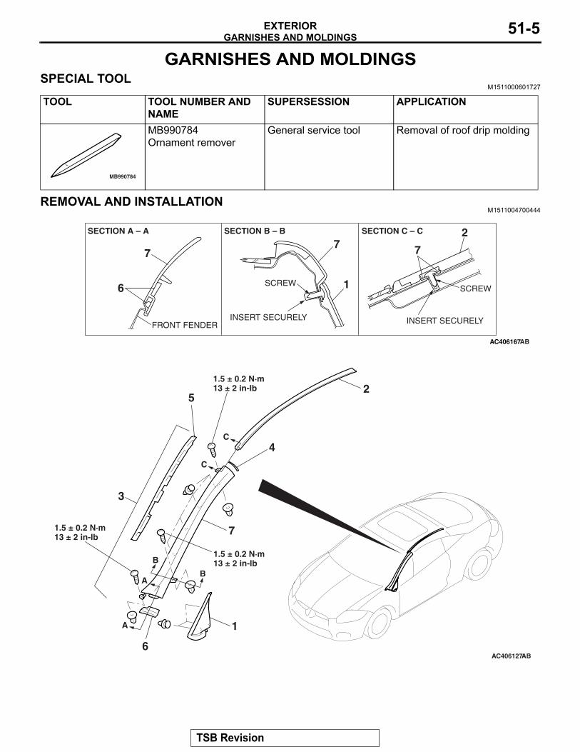
GARNISHES AND MOLDINGSEXTERIOR 51-5
GARNISHES AND MOLDINGSSPECIAL TOOL
M1511000601727
TOOL TOOL NUMBER AND NAME
SUPERSESSION APPLICATION
MB990784
MB990784 Ornament remover
General service tool Removal of roof drip molding
REMOVAL AND INSTALLATIONM1511004700444
AC406167AB
SECTION A – A SECTION B – B SECTION C – C
INSERT SECURELY
SCREWSCREW
INSERT SECURELYFRONT FENDER
1
77 7
2
6
AC406127AB
2
7
1
4
5
6
A
A
C
C
B
B
AB
3
1.5 ± 0.2 N·m13 ± 2 in-lb
1.5 ± 0.2 N·m13 ± 2 in-lb
1.5 ± 0.2 N·m13 ± 2 in-lb
TSB Revision

GARNISHES AND MOLDINGSEXTERIOR51-6
AC406760AB
ADHESIVE TAPE: DOUBLE-SIDED TAPE A: 10.0 mm ( 0.39 in ) WIDTH AND 1.52 mm ( 0.06 in ) THICKNESS
ROOF DRIP MOLDING
FRONT PILLAR GARNISH
A
REMOVAL • FRONT DECK COVER (REFER TO
WINDSHIELD WIPER P.51-13.)FRONT DELTA GARNISH REMOVAL STEP 1. FRONT DELTA GARNISHROOF DRIP MOLDING REMOVAL STEP 2. ROOF DRIP MOLDING
FRONT PILLAR GARNISH REMOVAL STEPS 3. FRONT PILLAR GARNISH
ASSEMBLY4. FRONT PILLAR GARNISH EDGE
PROTECTOR A5. FRONT PILLAR GARNISH EDGE
PROTECTOR B6. FRONT PILLAR GARNISH EDGE
PROTECTOR C7. FRONT PILLAR GARNISH
Required Special Tools:• MB990784: Ornament Remover
TSB Revision

SIDE AIR DAMEXTERIOR 51-7
SIDE AIR DAMREMOVAL AND INSTALLATION
M1511005500324
AC406120
AC406853AC406192
AB
B
B
A
A1
2
SECTION A – A SECTION B – B
BOLT CLIP CLIP
SCREW
2
1
1.5 ± 0.2 N·m13 ± 2 in-lb
REMOVAL STEPS 1. FRONT SIDE AIR DAM2. REAR SIDE AIR DAM
TSB Revision

UNDER COVEREXTERIOR51-8
UNDER COVERREMOVAL AND INSTALLATION
M1511019600205
AC406033
1
2
AB
3
REMOVAL STEPS • FRONT ENGINE ROOM UNDER
COVER (REFER TO P.51-2).1. SIDE UNDER COVER (LH)
2. PLUG3. SIDE UNDER COVER (RH)
REMOVAL STEPS (Continued)
TSB Revision

WINDSHIELD WIPER AND WASHEREXTERIOR 51-9
WINDSHIELD WIPER AND WASHERGENERAL DESCRIPTION
M1511000100956
WINDSHIELD WIPER AND WASHER OPERATION.
WINDSHIELD LOW-SPEED (AND HIGH-SPEED) WIPER OPERATION• If the windshield low-speed wiper switch is turned
to the ON position with the ignition switch at the "ACC" or "ON" position, the column switch sends a low-speed wiper ON and high-speed wiper OFF signals to the front-ECU. This turns the wiper sig-nal on and the wiper speed control relay off (low-speed), causing the wipers to operate at low-speed.
• If the windshield high-speed wiper switch is turned to the ON position, the column switch sends a low-speed wiper OFF and high-speed wiper ON signals to the front-ECU. This turns both the wiper signal and the wiper speed control relay on (high-speed), causing the wipers to operate at high-speed.
NOTE: The windshield wiper speed is adjustable with the built-in wiper speed control relay. High-speed operation takes place when the wiper speed control relay is set to "ON". Low-speed opera-tion takes place when the wiper speed control relay is set to "OFF"..
WINDSHIELD INTERMITTENT WIPER OPERATION (VEHICLE SPEED-SENSITIVE VARIABLE TYPE)ETACS-ECU uses the dial position of the variable intermittent wiper control switch and the vehicle speed signal sent by the combination meter to calcu-late the interval to be sent to the front-ECU.The front-ECU determines the intermittent time from the input SWS data signal, and turns ON the wind-shield wiper drive signal. When the wiper is at the STOP position, the windshield wiper auto-stop signal goes OFF, then turn OFF the windshield wiper drive signal. After the intermittent time from when the windshield wiper drive signal turned ON, the wind-shield wiper drive signal is turned ON again and the above operation is repeated.
NOTE: If the intermittent time is within 2 seconds, the wiper is operated consecutively at LOW-speed by the front-ECU..
WINDSHIELD MIST WIPER OPERATION• If the windshield mist wiper switch is turned to the
ON position with the ignition switch at the "ACC" or "ON" position, the mist wiper high-speed oper-ation signal is sent to the front-ECU. This signal turns on the wiper speed control relay, causing the wipers to work at high-speed while the mist switch is on.
• While the windshield mist wiper switch remains turned on when the intermittent mode is still work-ing, the wipers work as the mist wiper. However, the wipers return to the intermittent mode again when the switch is changed back to "INT" posi-tion.
• To prevent the windshield mist wiper from operat-ing when the windshield wiper switch is turned OFF, the windshield mist wiper does not work for 0.5 second after the windshield intermittent wiper switch, the windshield low-speed wiper switch and the windshield high-speed wiper switch are turned OFF.
.
WINDSHIELD WASHER OPERATION• If the windshield washer switch is turned to the
ON position with the ignition switch at "ACC" or "ON" position, the windshield washer ON signal is sent to the front-ECU. After 0.15 second, the windshield wiper signal turns on. After the wind-shield washer switch signal turns off, the wind-shield wiper signal turns off in 2 seconds.
• If the windshield washer switch is turned on while the windshield wiper is at intermittent mode, and the windshield washer switch is turned OFF within 0.2 second, the wiper works only once to perform mist operation. When the windshield washer switch is turned on for more than 0.2 sec-ond, the wiper performs the same movement as normal condition from the time when 0.2 second has elapsed, and then returns to intermittent operation.
TSB Revision

WINDSHIELD WIPER AND WASHEREXTERIOR51-10
WINDSHIELD WIPER AND WASHER DIAGNOSISM1511000700594
The windshield wiper and washer are controlled by the Simplified Wiring System (SWS). For trouble-shooting, refer to GROUP 54B, Symptom Chart P.54B-57.
NOTE: Even when the ETACS-ECU has failed, the windshield wipers can work at low speed as fail-safe mode. (Normally, the windshield wiper operates when the ignition switch is at the "ACC" position. But, if it enters the fail-safe mode, the wipers can operate only when the ignition switch is at the "ON" position.)
SPECIAL TOOLSM1511000601738
TOOL TOOL NUMBER AND NAME
SUPERSESSION APPLICATION
MB991910
MB991826
MB991958
MB991911
MB991914
MB991824
MB991827
MB991825
DO NOT USE
A
B
C
D
E
F
G
DO NOT USE
MB991958A: MB991824B: MB991827C: MB991910D: MB991911E: MB991914F: MB991825G: MB991826MUT-III sub assemblyA: Vehicle
Communication Interface (V.C.I.)
B: MUT-III USB CableC: MUT-III Main Harness
A (Vehicles with CAN communication system)
D: MUT-III Main Harness B (Vehicles without CAN communication system)
E: MUT-III Main Harness C (for Daimler Chrysler models only)
F: MUT-III Measurement Adapter
G: MUT-III Trigger Harness
MB991824-KITNOTE: G: MB991826 MUT-III Trigger Harness is not necessary when pushing V.C.I. ENTER key.
Windshield intermittent wiper check
For vehicles with CAN communication, use MUT-III main harness A to send simulated vehicle speed. If you connect MUT-III main harness B instead, the CAN communication does not function correctly.
CAUTION
TSB Revision

WINDSHIELD WIPER AND WASHEREXTERIOR 51-11
ON-VEHICLE SERVICE
WINDSHIELD INTERMITTENT WIPER INTERVAL CHECK
M1511018900076
Required Special Tools:• MB991958: Scan Tool (MUT-III Sub Assembly)
• MB991824: Vehicle Communication Interface (V.C.I.)• MB991827: MUT-III USB Cable• MB991910: MUT-III Main Harness A
If the windshield intermittent wiper interval control is operated, and/or vehicle speed changes, the wiper interval should change.
AC305412
AC404789AB
DATA LINKCONNECTOR
MB991824
MB991827
MB991910
CAUTIONTo prevent damage to scan tool MB991958, always turn the ignition switch to the "LOCK" (OFF) position before con-necting or disconnecting scan tool MB991958. 1. Connect scan tool MB991958 to the data link connector.2. Turn the ignition switch to the "ON" position.3. Operate scan tool MB991958 according to the procedure
below to display "Simulated Vehicle Speed Output."(1) Select "SYSTEM SELECT."(2) Select "SWS."(3) Select "Simulated Vehicle Speed Output."
4. Holding the windshield intermittent wiper interval control, input the simulated vehicle speed with scan tool MB991958 and check that the wiper interval changes as the vehicle speed changes.
5. If not, carry out the troubleshooting (Refer to GROUP 54B, Symptom Chart P.54B-57).
TSB Revision

WINDSHIELD WIPER AND WASHEREXTERIOR51-12
WINDSHIELD WASHER FLUID EJECTION CHECKM1511018400093
AC307151 AB
WINDSHIELD WIPER WIPING AREA
The windshield washer nozzle aiming cannot be adjusted. If the washer nozzles do not spray washer fluid within the windshield wiper wiping area, check the nozzles as follows:1. Check that the windshield washer nozzles are fitted on the
hood correctly, and reinstall them if necessary.2. If the windshield washer nozzles are damaged, replace
them (Refer to P.51-18).
TSB Revision

WINDSHIELD WIPER AND WASHEREXTERIOR 51-13
WINDSHIELD WIPERREMOVAL AND INSTALLATION
M1511007900351
AC406215AC406567
AB
1
9
3
7
8.0 ± 2.0 N·m71 ± 18 in-lb
8.0 ± 2.0 N·m71 ± 18 in-lb
A
30 ± 3.0 N·m22 ± 2 ft-lb
30 ± 3.0 N·m22 ± 2 ft-lb
7
8
4
10
2
56
6
SCREW
4
SECTION B – B
AC406001
VIEW A
: CLIP POSITIONS : SCREW POSITIONS C
C
6
44
AB
B
EF
FH
H
E
GG
B
TSB Revision

WINDSHIELD WIPER AND WASHEREXTERIOR51-14
AC406217
AC406164
SECTION C – C SECTION E – E
SECTION F – F SECTION G – G SECTION H – H
6
6
6
6
4 44
CLIP CLIP
CLIP
CLIPCLAW
PIN
CLAW
VIEW D
D
HOOD WEATHERSTRIP
HOOD
FRONT PILLAR GARNISH
FRONT PILLAR GARNISH
AB
WIPER ARM AND BLADE REMOVAL STEPS 1. CAP
>>A<< 2. WINDSHIELD WIPER BLADE>>B<< 3. WINDSHIELD WIPER ARM
WINDSHIELD WIPER MOTOR AND LINK ASSEMBLY REMOVAL STEPS 4. FRONT DECK COVER5. FRONT DECK GARNISH
ASSEMBLY6. FRONT DECK GARNISH7. FRONT DECK GARNISH COVER
8. WIPER PIVOT CAP<<A>> 9. WINDSHIELD WIPER LINK <<A>> 10. WINDSHIELD WIPER MOTORNOTE: For removal and installation of the wiper and washer switch, refer to GROUP 54A, Column switch P.54A-149.
REMOVAL SERVICE POINT.
<<A>> WINDSHIELD WIPER LINK/WINDSHIELD WIPER MOTOR REMOVAL
AC406406
VEHICLE FRONT
GROMMET
AB
WINDSHIELD
WIPER LINK AND MOTOR
Disengage the harness grommet as shown in the illustration before removing the wiper link and motor.
WINDSHIELD WIPER MOTOR AND LINK ASSEMBLY REMOVAL STEPS
TSB Revision

WINDSHIELD WIPER AND WASHEREXTERIOR 51-15
INSTALLATION SERVICE POINTS.
>>A<< WINDSHIELD WIPER BLADE INSTALLA-TION
AC101090AD
WIPER BLADEBACKING
BACKING
A
A
SECTION A – A
WIPERBLADE BACKING
CAUTIONEnsure that the backings are bent in the direction indi-cated, and then install the backings to the wiper blade rub-ber.
.
>>B<< WINDSHIELD WIPER ARM INSTALLATION
AC406011ABFRONT DECK GARNISH FRONT DECK GARNISH
FRONT DECK GARNISH
ALIGN WIPER BLADE TO MARKING ON WINDSHIELD
MARKING ON WINDSHIELD
WIPER ARM AND BLADE ASSEMBLY (LH)
SECTION A – A SECTION B – B
A
A
B
B
61 mm(2.40 in)
34 mm(1.33 in)
WIPER ARM AND BLADE ASSEMBLY (RH)
MARKING ON WINDSHIELD
Install the wiper arm and blade at the position specified above.
INSPECTIONM1511008000221
WINDSHIELD WIPER MOTOR CHECKRemove the windshield wiper motor and inspect it at the har-ness connector..
TSB Revision

WINDSHIELD WIPER AND WASHEREXTERIOR51-16
Windshield Wiper Motor at Low or High Speed Operation
4 531 2
4 531 2
4 531 2
AC406646
CHECK OPERATION
LOW SPEED
HIGH SPEED
AB
WOODEN BLOCK
Connect the battery to the windshield wiper motor to inspect the operation of motor rotation at low or high speed.
.
Windshield Wiper Motor at Stop Position Operation
4 531 2
4 531 2
4 531 2
AC406647
STOP POSITION CHECK
(B) AUTOMATIC STOP
(A) LOW SPEED
+5º-10º
AB
0º12´ WOODEN BLOCK
1. Connect the battery to the windshield wiper motor as shown in the illustration (A).
2. Run the windshield wiper motor at low speed, then disconnect the battery in the middle of the motor rotation and check to see that the motor stops.
3. As shown in the illustration (B), connect the terminals of the windshield wiper motor connector.
4. Check to see that the windshield wiper motor runs at low speed and then stops at the automatic stop position.
TSB Revision

WINDSHIELD WIPER AND WASHEREXTERIOR 51-17
WINDSHIELD WIPER SWITCH CHECK
212223242526272829303132
AC406223
UPPER SIDE
AB
Check continuity between the switch terminals.
SWITCH POSITION TESTER CONNECTION
SPECIFIED CONDITION
OFF 23 − 32, 23 − 31, 23 − 30, 23 − 21
Open circuit
Windshield mist wiper switch
23 − 32 Less than 2 ohms
Windshield intermittent wiper switch
23 − 31
Windshield low-speed wiper switch
23 − 30
Windshield high-speed wiper switch
21 − 23
WINDSHIELD INTERMITTENT WIPER INTERVAL CHECK
212223242526272829303132
AC406794
UPPER SIDE
AB
Check that the resistance varies between 0 and 1 kΩ when the windshield intermittent interval is turned from FAST to SLOW by after measuring resistance between connector terminals 27 and 28 at the column switch.
TSB Revision

WINDSHIELD WIPER AND WASHEREXTERIOR51-18
WINDSHIELD WASHERREMOVAL AND INSTALLATION
M1511008200720
AC405983
AC406237
1
2
53
4
6
SECTION A – A
1
CLAWCLAW
12 ± 1.0 N·m101 ± 14 in-lb
AB
A
A
WINDSHIELD WASHER NOZZLE REMOVAL STEPS • WINDSHIELD WASHER TUBE
CONNECTION1. WINDSHIELD WASHER NOZZLEWASHER TUBE REMOVAL STEPS • WINDSHIELD WASHER NOZZLE
CONNECTION 2. WASHER TUBEWASHER TANK REMOVAL STEPS • ENGINE ROOM UNDER COVER RH
(REFER TO P.51-8).• FRONT SPLASH SHIELD RH
MOUNTING CLIPS (REFER TO GROUP 42, FENDER P.42-10).
• WASHER TUBE CONNECTIONS3. WINDSHIELD WASHER TANK4. CAP
5. WINDSHIELD WASHER MOTOR6. REAR WASHER MOTORWASHER MOTOR REMOVAL STEPS • ENGINE ROOM UNDER COVER RH
(REFER TO P.51-8).• FRONT SPLASH SHIELD RH
MOUNTING CLIPS (REFER TO GROUP 42, FENDER P.42-10).
• WASHER TUBE CONNECTIONS5. WINDSHIELD WASHER MOTOR6. REAR WASHER MOTOR
NOTE: For removal and installation of the wiper and washer switch, refer to GROUP 54A, Column switch P.54A-149.
WASHER TANK REMOVAL STEPS
TSB Revision

WINDSHIELD WIPER AND WASHEREXTERIOR 51-19
INSPECTIONM1511008300244
WINDSHIELD WASHER MOTOR CHECK1. Remove the washer tank assembly with the washer hose
attached. Then fill the washer tank with water.2.
AC500049
21
Check to see that the water is vigorously sprayed when connecting the positive battery terminal to terminal number 2 and terminal number 1 to ground.
WINDSHIELD WASHER SWITCH CHECK
212223242526272829303132
AC406223
UPPER SIDE
AB
SWITCH POSITION TESTER CONNECTION
SPECIFIED CONDITION
OFF 22 − 23 Open circuit
Windshield washer switch ON
22 − 23 Less than 2 ohms
TSB Revision

REAR WIPER AND WASHEREXTERIOR51-20
REAR WIPER AND WASHERGENERAL DESCRIPTION
M1511000100967
REAR WIPER AND WASHER OPERATION.
REAR WIPER OPERATION• If the rear wiper and washer switch is turned to
the "INT" position with the ignition switch at "ACC" or "ON" position, the ETACS-ECU causes the rear wiper to operate continuously 2 times, then intermittently at 8-second intervals.
• If the selector lever (or gearshift lever) is moved to the "R" position when the rear wiper and washer switch is turned to the "INT" position and the ignition switch at "ACC" or "ON" position, the transmission range switch (or backup light switch) "R" turns ON. 1 second later, the ETACS-ECU causes the rear wiper to operate continuously 2 times to ensure good rearward visibility. The ETACS-ECU then causes the rear wiper to operate intermittently again at 8-second intervals.
.
REAR WASHER OPERATION• If the rear wiper and washer switch is turned to
the ON (washer) position with the ignition switch at "ACC" or "ON" position, the rear washer ON signal is sent to the ETACS-ECU, causing the rear wiper signal to turn on after 0.9 second. After the rear washer switch signal turns off, the rear wiper signal turns off in 3 seconds.
• If the rear wiper and washer switch is turned to the ON (washer) position while the rear wiper is at intermittent mode, the rear washer works for that period when the washer switch remains on. Then the rear wiper returns to the intermittent mode.
REAR WIPER AND WASHER DIAGNOSISM1511021100069
The rear wiper and washer are controlled by the Sim-plified Wiring System (SWS). For troubleshooting, refer to GROUP 54B, Symptom Chart P.54B-57.
ON-VEHICLE SERVICE
CHECK OF REAR WIPER OPERATION WHEN SELECTOR LEVER (OR GEARSHIFT LEVER) IS AT "R" POSITION
M1511024500044
1. When the selector lever (or gearshift lever) is moved to the "R" position with the rear wiper switch at the "INT" position, the wiper should operate 2 to 3 times at low speed after approximately 1 second.
2. If not, carry out troubleshooting (Refer to GROUP 54B, Symptom Chart P.54B-57).
TSB Revision

REAR WIPER AND WASHEREXTERIOR 51-21
REAR WIPER AND WASHERREMOVAL AND INSTALLATION
M1511008500419
AC405982
AC406238
7.4 ± 1.4 N·m65 ± 13 in-lb
7.4 ± 1.4 N·m65 ± 13 in-lb
3
1
2
4
5
6
AB
SECTION A – A6
CLAWHOOK
A
A
7
REAR WIPER MOTOR ASSEMBLY REMOVAL STEPS 1. COVER
>>C<< 2. REAR WIPER ARM>>B<< 3. REAR WIPER BLADE>>A<< 4. GROMMET
• LIFTGATE TRIM (REFER TO GROUP 52A, LIFTGATE TRIM P.52A-36.)
5. REAR WIPER MOTOR ASSEMBLYREAR WASHER NOZZLE REMOVAL STEPS • LIFTGATE TRIM (REFER TO
GROUP 52A, LIFTGATE TRIM P.52A-36.)
• REAR WASHER TUBE CONNECTION
6. REAR WASHER NOZZLE
REAR WASHER TUBE REMOVAL STEPS • QUARTER WINDOW FLANGE TRIM
<RH> (REFER TO GROUP 52A, TRIMS P.52A-31.)
• REAR WASHER NOZZLE CONNECTION
7. REAR WASHER TUBENOTE: For removal and installation of the wiper and washer switch, refer to GROUP 54A, Column Switch P.54A-149.NOTE: For removal and installation of the washer tank assembly and rear washer motor, refer to Wind-shield Wiper and Washer P.51-18.
TSB Revision

REAR WIPER AND WASHEREXTERIOR51-22
INSTALLATION SERVICE POINTS.
>>A<< GROMMET INSTALLATION
AC406363
CERAMIC END LINE
AB
5˚ ± 15˚ARROW
GROMMET
WIPER ARM AND BLADE
Install the grommet so that the arrow points backward.
.
>>B<< REAR WIPER BLADE INSTALLATION
AC101090AD
WIPER BLADEBACKING
BACKING
A
A
SECTION A – A
WIPERBLADE BACKING
CAUTIONEnsure that the backings are bent in the direction indi-cated, and then install the backings to the wiper blade rub-ber.
.
>>C<<REAR WIPER ARM INSTALLATION
AC406327AB
WIPER ARM AND BLADE
CERAMIC END LINE
GLASS END LINE
Install the wiper arm and blade assembly so that it is positioned on the ceramic end line.
TSB Revision

REAR WIPER AND WASHEREXTERIOR 51-23
INSPECTIONM1511008600319
REAR WIPER MOTOR CHECK
1 2 3 4
1 2 3 4
1 2 3 4
AC406325AC
(A) OPERATION CHECK
(B) STOP POSITION CHECK
Inspect the rear wiper motor by removing the harness connec-tor with the motor attached to the vehicle..
WIPER MOTOR OPERATIONConnect the battery to the rear wiper motor as shown in figure (A) and check the motor operation..
WIPER MOTOR AT STOP POSITION OPERATION1. Connect the battery to the rear wiper motor as shown in fig-
ure (A).2. Disconnect the battery cable from the rear wiper motor
while it is turning and then check to see that the motor stops.
3. Re-connect the battery as shown in figure (B).4. Check to see that the rear wiper motor runs and then stops
at the automatic stop position.
REAR WASHER MOTOR CHECK1. Remove the rear washer tank assembly with the washer
hose attached. Then fill the washer tank with water.2.
AC500050
21
Check to see that the water is vigorously sprayed when connecting the positive battery terminal to terminal number 2 and terminal number 1 to ground.
TSB Revision

REAR WIPER AND WASHEREXTERIOR51-24
REAR WASHER FLUID EJECTION CHECK
AC406370
UNIT: mm (in)
40(1.57)
CERAMIC END LINE
REAR WASHER NOZZLE
10(0.39)
10(0.39)35(1.38)
AB
5.2˚
GLASS END LINE
WIPER ARM AND BLADE
Move the nozzle to adjust the position so that washer fluid is sprayed in the area shown in the illustration.
REAR WIPER AND WASHER SWITCH CHECK
212223242526272829303132
AC406223
UPPER SIDE
AB
Check continuity between the switch terminals.
SWITCH POSITION TESTER CONNECTION
SPECIFIED CONDITION
OFF 25 − 26, 25 − 29 Open circuit
Rear wiper switch 25 − 26 Less than 2 ohms
Rear washer switch 25 − 29 Less than 2 ohms
TSB Revision

MARKEXTERIOR 51-25
MARKREMOVAL AND INSTALLATION
M1511011801275
AC405739AC404539AC405644
1
2
3
4
5AC
AA
B B
SECTION B – B
SECTION A – A
2
CLIP
1N
N
N
1. FRONT THREE-DIAMOND MARK (REFER TO FRONT BUMPER P.51-3)
2. REAR THREE-DIAMOND MARK
>>A<< 3. ECLIPSE MARK>>A<< 4. GT MARK<3.8L ENGINE>>>A<< 5. V6 MARK<3.8L ENGINE>
TSB Revision

MARKEXTERIOR51-26
INSTALLATION SERVICE POINT.
>>A<< MARK INSTALLATION
AC405747
B A
B
ECLIPSE MARK
BODY CENTER LINE
3. ECLIPSE MARK4. GT MARK<3.8L ENGINE>5. V6 MARK<3.8L ENGINE>
AB
ALIGN TO BUMPER PRESS LINE
AC405959
VIEW A SECTION B – B
ALIGN TO BUMPER PRESS LINE
GT MARK V6 MARK
ALIGN TO BUMPER CORNER
BUMPER PRESS LINE
LETTER "I"
REAR THREE-DIAMOND MARK
FOAM TEMPLATE(DISCARD)
AB
1. Installation position Attach each mark to the position shown in the illustration.
2. Installation procedure(1) Use 3M™ AAD Part number 8906 or equivalent to clean
the mark installation surfaces on the body.CAUTION
When attaching the marks, the ambient temperature should be 20 − 38° C (60 − 100° F) and the air should be com-pletely free of dust. If the ambient temperature is lower than 20° C (60° F), the marks and the places on the vehicle body where the marks are to be attached should be heated to 20 − 38° C (60 − 100° F).
(2) Peel off the protection sheet on the back of the marks to affix it in position.
TSB Revision

DOOR MIRROREXTERIOR 51-27
DOOR MIRRORGENERAL DESCRIPTION
M1511000100978
OPERATION DOOR MIRRORRemote Controlled Mirror Operation• The mirror on the door mirror moves up/down
and left/right by operating the remote controlled door mirror switch when the ignition switch is at the "ON" or "ACC" position.
Heated Door Mirror Operation• The rear window defogger relay switch is acti-
vated (ON) by turning on the A/C-ECU built-in rear window defogger switch when the ignition switch is in the "ON" position. When the rear win-dow defogger relay is turned ON, power is sup-
plied to the rear window defogger and door mirror, and the heater of the door mirror (heated door mirror) starts operations. The rear window defogger comes with a timer function and will automatically turn OFF the switch approximately 17 minutes after the rear window defogger switch is turned ON. The heated door mirror operations are also terminated along with the rear window defogger, at this time.
HEATED DOOR MIRROR DIAGNOSISTROUBLESHOOTING STRATEGY
M1511014600170Diagnosis should be carried out by the following pro-cedures.1. Gather the information from the customer.2. Verify that the condition described by the
customer exists.
3. Find the malfunction by the following Symptom Chart.
4. Verify the malfunction is eliminated.
SYMPTOM CHARTM1511015000364
SYMPTOM INSPECTION PROCEDURE
REFERENCE PAGE
All heated door mirrors do not operate 1 P.51-28The right or left heated door mirror does not operate 2 P.51-33
TSB Revision

DOOR MIRROREXTERIOR51-28
SYMPTOM PROCEDURES
INSPECTION PROCEDURE 1: All Heated Door Mirrors do not Operate
Heated Door Mirror Circuit
JUNCTION BLOCK DEFOGGER
RELAY
DEFOGGER
REMOTE CONTROLLED MIRROR (LH)
REMOTE CONTROLLED MIRROR (RH)
MIRROR HEATER
MIRROR HEATER
6
AC406889
CONNECTOR: C-09
AB AC406888
CONNECTOR: C-25
AB
TSB Revision

DOOR MIRROREXTERIOR 51-29
AC406890
JUNCTION BLOCK (FRONT VIEW)CONNECTOR: C-215
AB
AC406892
CONNECTOR: E-12
AB
E-12 (LW)
AC406891
E-01 (LW)
CONNECTOR: E-01
AB
.
CIRCUIT OPERATIONIf both of the door mirror heaters do not operate nor-mally it may be due to a malfunction in the rear win-dow defogger system..
TROUBLESHOOTING HINTS• Malfunction of the rear window defogger system• The wiring harness or connectors may have
loose, corroded or damaged terminals, or termi-nals pushed back in the connector.
DIAGNOSISRequired Special Tools:• MB991223: Test Harness Set
STEP 1. Check the rear window defogger.Check that the rear window defogger works normally as fol-lows.(1) Turn the ignition switch to the "ON" position.(2) Push the rear window defogger switch to operate the
defogger.Q: Does the defogger work normally?
YES : Go to Step 2.NO : Because of malfunction of the rear window defogger,
carry out the troubleshooting (Refer to GROUP 55A, Manual A/C Diagnosis P.55A-98).
TSB Revision

DOOR MIRROREXTERIOR51-30
STEP 2. Check the remote controlled mirror (RH) connector E-01 and junction block connector C-215 for loose, corroded or damaged terminals, or terminals pushed back in the connector.
AC406911
CONNECTOR: E-01
HARNESS SIDE
AC
E-01 (LW)
AC406912
JUNCTION BLOCK (FRONT VIEW)CONNECTOR: C-215
AB
HARNESS SIDE
Q: Are the remote controlled mirror (RH) connector E-01 and junction block connector C-215 in good condition?YES : Go to Step 3.NO : Repair or replace the damaged component(s). Refer
to GROUP 00E, Harness Connector Inspection P.00E-2. Check if the door mirrors works normally.
TSB Revision

DOOR MIRROREXTERIOR 51-31
STEP 3. Check the wiring harness between the remote controlled mirror (RH) connector E-01 (terminal 1) and junction block connector C-215 (terminal 3).
AC406911
CONNECTOR: E-01
HARNESS SIDE
AC
E-01 (LW)
AC406912
JUNCTION BLOCK (FRONT VIEW)CONNECTOR: C-215
AB
HARNESS SIDE
NOTE:
AC406913
CONNECTOR: C-09
AB
Also check intermediate connector C-09 for loose, cor-roded or damaged terminals, or terminals pushed back in the connector. If intermediate connector C-09 is damaged, repair or replace the damaged component(s) as described in GROUP 00E, Harness Connector Inspection P.00E-2.Q: Is the wiring harness between remote controlled mirror
(RH) connector E-01 (terminal 1) and junction block connector C-215 (terminal 3) in good condition?YES : Go to step 4.NO : Repair the wiring harness as necessary. Check if all
heated door mirrors work normally.
TSB Revision

DOOR MIRROREXTERIOR51-32
STEP 4. Check remote controlled mirror (LH) connector E-12.
AC406914
CONNECTOR: E-12
HARNESS SIDE
AB
E-12 (LW)
Q: Is remote controlled mirror (LH) connector E-12 in good condition?YES : Go to Step 5.NO : Repair or replace the damaged component(s). Check
if all heated door mirrors work normally.
STEP 5. Check the wiring harness between remote controlled mirror (LH) connector E-12 (terminal 1) and junction block connector C-215 (terminal 3).
AC406914
CONNECTOR: E-12
HARNESS SIDE
AB
E-12 (LW)
AC406912
JUNCTION BLOCK (FRONT VIEW)CONNECTOR: C-215
AB
HARNESS SIDE
TSB Revision

DOOR MIRROREXTERIOR 51-33
NOTE:
AC406931
CONNECTOR: C-25
AB
Also check intermediate connector C-25 for loose, cor-roded or damaged terminals, or terminals pushed back in the connector. If intermediate connector C-25 is damaged, repair or replace the damaged component(s) as described in GROUP 00E, Harness Connector Inspection P.00E-2.Q: Is the wiring harness between remote controlled mirror
(RH) connector E-12 (terminal 1) and junction block connector C-215 (terminal 3) in good condition?YES : The procedure is complete.NO : Repair the wiring harness as necessary. Check if the
all heated door mirrors work normally.
INSPECTION PROCEDURE 2: The Right or Left Heated Door Mirror does not Operate
Heated Door Mirror Circuit
JUNCTION BLOCK DEFOGGER
RELAY
DEFOGGER
REMOTE CONTROLLED MIRROR (LH)
REMOTE CONTROLLED MIRROR (RH)
MIRROR HEATER
MIRROR HEATER
6
TSB Revision

DOOR MIRROREXTERIOR51-34
AC406889
CONNECTOR: C-09
AB AC406888
CONNECTOR: C-25
AB
AC406890
JUNCTION BLOCK (FRONT VIEW)CONNECTOR: C-215
AB AC406891
E-01 (LW)
CONNECTOR: E-01
AB
AC406892
CONNECTOR: E-12
AB
E-12 (LW)
.
CIRCUIT OPERATIONIf either of the heated door mirrors do not operate normally, it may be due to malfunctions in the heated door mirror circuit or door mirror..
TROUBLESHOOTING HINTS• Malfunction of the heated door mirror circuit• Malfunction of the door mirror• The wiring harness or connectors may have
loose, corroded, or damaged terminals, or termi-nals pushed back in the connector.
DIAGNOSIS
STEP 1. Verify the operation of each heated door mirror.Q: Which door mirror does not heat?
Door mirror (LH) : Go to Step 2.Door mirror (RH) : Go to Step 8.
TSB Revision

DOOR MIRROREXTERIOR 51-35
STEP 2. Check remote controlled mirror (LH) connector E-12 for loose, corroded or damaged terminals, or terminals pushed back in the connector.
AC406914
CONNECTOR: E-12
HARNESS SIDE
AB
E-12 (LW)
Q: Is remote controlled mirror (LH) connector E-12 in good condition?YES : Go to Step 3.NO : Repair or replace the damaged component(s). Refer
to GROUP 00E, Harness Connector Inspection P.00E-2. And then check to see that the heater function of the door mirror (LH) operates normally.
STEP 3. Check the heater of the door mirror (LH).CAUTION
When relocating the car between locations of extremely different temperatures (warm and cold), leave the car in the location for a while to adapt to the temperature prior to checking it.
AC406015ABTEMPERATURE (˚C)-10 0
8
9
10
11
12
13
14
15
10 20 30 40
LOWER LIMIT VALUE
UPPER LIMIT VALUE
RE
SIS
TAN
CE
(
)
Check to see that the resistance shown in the graph is almost satisfied when measuring the resistance between terminal 1 and 3 of the remote controlled mirror (LH) connector E-12.Q: Is the resistance normal?
YES : Go to Step 4.NO : Replace the door mirror (LH). And then check to see
that the heater function of the door mirror (LH) is operating normally.
TSB Revision

DOOR MIRROREXTERIOR51-36
STEP 4. Check the ground circuit between remote controlled mirror (LH) connector E-12 and ground for open circuit. Measure the resistance at remote controlled mirror (LH) connector E-12.
AC406914
CONNECTOR: E-12
HARNESS SIDE
AB
E-12 (LW)
(1) Disconnect remote controlled mirror (LH) connector E-12 and check at the wiring harness side connector.
AC307127
CONNECTOR: E-12(HARNESS SIDE)
AE
(2) Measure the resistance value between terminal 3 and ground.
• The resistance should be 2 ohms or less.Q: Is the measured resistance 2 ohms or less?
YES : Go to Step 6.NO : Go to Step 5.
STEP 5. Check the wiring harness between remote controlled mirror (LH) connector E-12 (terminal 3) and ground.
AC406914
CONNECTOR: E-12
HARNESS SIDE
AB
E-12 (LW)
TSB Revision

DOOR MIRROREXTERIOR 51-37
NOTE:
AC406931
CONNECTOR: C-25
AB
Also check intermediate connector C-25 for loose, cor-roded or damaged terminals, or terminals pushed back in the connector. If intermediate connector C-25 is damaged, repair or replace the damaged component(s) as described in GROUP 00E, Harness Connector Inspection P.00E-2.Q: Is the wiring harness between remote controlled mirror
(LH) connector E-12 (terminal 3) and ground in good condition?YES : No action is necessary and testing is complete.NO : The wiring harness may be damaged. Repair the
wiring harness as necessary. And then check to see that the heater function of the door mirror (LH) operates normally.
STEP 6. Check junction block C-215 for loose, corroded damaged terminal, or terminals pushed back in the connector.
AC406890
JUNCTION BLOCK (FRONT VIEW)CONNECTOR: C-215
AB
Q: Is junction block C-215 in good condition?YES : Go to Step 7.NO : Repair or replace the damaged component(s). Refer
to GROUP 00E, Harness Connector Inspection P.00E-2. And then check to see that the heater function of the door mirror (LH) operates normally.
TSB Revision

DOOR MIRROREXTERIOR51-38
STEP 7. Check the wiring harness between remote controlled mirror (LH) connector E-12 (terminal 1) and junction block connector C-215 (terminal 3).
AC406914
CONNECTOR: E-12
HARNESS SIDE
AB
E-12 (LW)
AC406912
JUNCTION BLOCK (FRONT VIEW)CONNECTOR: C-215
AB
HARNESS SIDE
NOTE:
AC406931
CONNECTOR: C-25
AB
Also check intermediate connector C-25 for loose, cor-roded or damaged terminals, or terminals pushed back in the connector. If intermediate connector C-25 is damaged, repair or replace the damaged component(s) as described in GROUP 00E, Harness Connector Inspection P.00E-2.Q: Is the wiring harness between remote controlled mirror
(LH) connector E-12 (terminal 1) and junction block connector C-215 (terminal 3) in good condition?YES : No action is necessary and testing is complete.NO : Repair the wiring harness as necessary. And then
check to see that the heater function of the door mirror (LH) operates normally.
TSB Revision

DOOR MIRROREXTERIOR 51-39
STEP 8. Check the remote controlled mirror (RH) connector E-01 for loose, corroded or damaged terminals, or terminals pushed back in the connector.
AC406911
CONNECTOR: E-01
HARNESS SIDE
AC
E-01 (LW)
Q: Is the remote controlled mirror (RH) connector E-01 in good condition?YES : Go to Step 9.NO : Repair or replace the damaged component(s). Refer
to GROUP 00E, Harness Connector Inspection P.00E-2. And then check to see that the heater function of the door mirror (RH) operates normally.
STEP 9. Check the heater function of the door mirror (RH).CAUTION
When relocating the car between locations of extremely different temperatures (warm and cold), leave the car in the location for a while to adapt to the temperature prior to checking it.
AC406015ABTEMPERATURE (˚C)-10 0
8
9
10
11
12
13
14
15
10 20 30 40
LOWER LIMIT VALUE
UPPER LIMIT VALUE
RE
SIS
TAN
CE
(
)
Check to see that the resistance shown in the graph is almost satisfied when measuring the resistance between terminal 1 and 3 of the door mirror (RH) connector E-01.Q: Is the resistance normal?
YES : Go to Step 10.NO : Replace the door mirror (RH). And then check to see
that the heater function of the door mirror (RH) operates normally.
TSB Revision

DOOR MIRROREXTERIOR51-40
STEP 10. Check the ground circuit between remote controlled mirror (RH) connector E-01 and ground for open circuit. Measure the resistance at remote controlled mirror (RH) connector E-01.
AC406911
CONNECTOR: E-01
HARNESS SIDE
AC
E-01 (LW)
(1) Disconnect remote controlled mirror (RH) connector E-01, and check at the wiring harness side connector.
AC307127
CONNECTOR: E-01(HARNESS SIDE)
AF
(2) Measure the resistance value between terminal 3 and ground.
• The resistance should be 2 ohms or less.Q: Is the measured resistance 2 ohms or less?
YES : Go to Step 12.NO : Go to Step 11.
STEP 11. Check the wiring harness between remote controlled mirror (RH) connector E-01 (terminal 3) and ground.
AC406911
CONNECTOR: E-01
HARNESS SIDE
AC
E-01 (LW)
TSB Revision

DOOR MIRROREXTERIOR 51-41
NOTE:
AC406913
CONNECTOR: C-09
AB
Also check intermediate connector C-09 for loose, cor-roded or damaged terminals, or terminals pushed back in the connector. If intermediate connector C-09 is damaged, repair or replace the damaged component(s) as described in GROUP 00E, Harness Connector Inspection P.00E-2.Q: Is the wiring harness between remote controlled mirror
(RH) connector E-01 (terminal 3) and ground in good condition?YES : No action is necessary and testing is complete.NO : The wiring harness may be damaged. Repair the
wiring harness as necessary. And then check to see that the heater function of the door mirror (RH) operates normally.
STEP 12. Check junction block C-215 for loose, corroded damaged terminal, or terminals pushed back in the connector.
AC406890
JUNCTION BLOCK (FRONT VIEW)CONNECTOR: C-215
AB
Q: Is junction block C-215 in good condition?YES : Go to Step 13.NO : Repair or replace the damaged component(s). Refer
to GROUP 00E, Harness Connector Inspection P.00E-2. And then check to see that the heater function of the door mirror (RH) operates normally.
TSB Revision

DOOR MIRROREXTERIOR51-42
STEP 13. Check the wiring harness between remote controlled mirror (RH) connector E-01 (terminal 1) and junction block connector C-215 (terminal 3).
AC406911
CONNECTOR: E-01
HARNESS SIDE
AC
E-01 (LW)
AC406912
JUNCTION BLOCK (FRONT VIEW)CONNECTOR: C-215
AB
HARNESS SIDE
NOTE:
AC406913
CONNECTOR: C-09
AB
Also check intermediate connector C-09 for loose, cor-roded or damaged terminals, or terminals pushed back in the connector. If intermediate connector C-09 is damaged, repair or replace the damaged component(s) as described in GROUP 00E, Harness Connector Inspection P.00E-2.Q: Is the wiring harness between remote controlled mirror
(RH) connector E-01 (terminal 1) and junction block connector C-215 (terminal 3) in good condition?YES : No action is necessary and testing is complete.NO : Repair the wiring harness as necessary. And then
check to see that the heater function of the door mirror (RH) operates normally.
TSB Revision

DOOR MIRROREXTERIOR 51-43
DOOR MIRRORREMOVAL AND INSTALLATION
M1511006400665
AC406682AB
1
3
2
3A
A
5.0 ± 1.0 N·m44 ± 9 in-lb
SECTION A – A
BOLTS
AC406305
SECTION B – B
CLAW
CLAW
: CLAW POSITIONS
B
B
4
5
5
4
4
5
AB
DOOR MIRROR REMOVAL STEPS • FRONT DOOR TRIM (REFER TO
GROUP 52A, DOOR TRIMS P.52A-34).
<<A>> 1. MIRROR2. HEATER TERMINAL (VEHICLES
WITH HEATED DOOR MIRROR)<<B>> 3. DOOR MIRROR ASSEMBLY
REMOTE CONTROLLED MIRROR SWITCH REMOVAL STEPS 4. INSTRUMENT PANEL SWITCH
ASSEMBLY5. REMOTE CONTROLLED MIRROR
SWITCH
TSB Revision

DOOR MIRROREXTERIOR51-44
REMOVAL SERVICE POINTS.
<<A>> MIRROR REMOVAL
AC406306AC
SECTION A – AMIRROR
FLAT-TIPPEDSCREWDRIVER
FLAT-TIPPEDSCREWDRIVER
MIRROR
PROTECTIVE TAPE
PROTECTIVE TAPE
NOTCH
CLAW
CLAW
CLAWS
PIVOT PLATE
AAA
A
CAUTIONThe claws of the mirror are prone to breakage when work-ing in cold temperatures. Always warm up the mirror claws and their periphery to 20° C(60° F) or higher before han-dling.Slant the mirror upward with your hands. Then insert a flat-tipped screwdriver wrapped with protective tape between the pivot plate and mirror through the notch from behind the mirror. Now pry off the mirror claws and remove mirror as shown.
.
<<B>> DOOR MIRROR ASSEMBLY REMOVAL
AC407168AC
BOLTS
DOOR MIRROR ASSEMBLY
DOOR INNER HANDLE
SEAL TAPE
FRONT OF VEHICLEVIEW A
A
CAUTIONWhen loosening or tightening the door mirror assembly mounting bolts, use a magnetic wrench to prevent bolts from dropping into the door panel cavity.
TSB Revision

DOOR MIRROREXTERIOR 51-45
INSPECTIONM1511006500424
REMOTE CONTROLLED MIRROR OPERATION CHECK
AC406318
Check that the mirror moves as described in the table when each terminal is connected to the battery.
BATTERY CONNECTION DIRECTION OPERATION
• Connect terminal 6 to the negative battery terminal.
• Connect terminal 4 to the positive battery terminal.
Up
• Connect terminal 6 to the positive battery terminal.
• Connect terminal 4 to the negative battery terminal.
Down
• Connect terminal 6 to the negative battery terminal.
• Connect terminal 5 to the positive battery terminal.
Right
• Connect terminal 6 to the positive battery terminal.
• Connect terminal 5 to the negative battery terminal.
Left
DOOR MIRROR CONTROL SWITCH CONTINUITY CHECK
AC406691
21 43
5 109876 11
SWITCH POSITION
TESTER CONNECTION SPECIFIED CONDITION
OFF 9 − 2, 9 − 3, 9 − 6, 9 − 10, 9 − 11, 1 − 2,1 − 3, 1 − 6, 1 − 10, 1 − 11
Open circuit
Left side
OFF 9 − 6, 9 − 10, 9 − 11, 1 − 6, 1 − 10, 1 − 11
Open circuit
Up 1 − 6, 9 − 11 Less than 2 ohmsDown 1 − 11, 6 − 9
Right 1 − 6, 9 − 10
Left 1 − 10, 6 − 9
Right side
OFF 9 − 2, 9 − 3, 9 − 6, 1 − 2, 1 − 3, 1 − 6
Open circuit
Up 1 − 6, 3 − 9 Less than 2 ohmsDown 1 − 3, 6 − 9
Right 1 − 6, 2 − 9
Left 1 − 2, 6 − 9
TSB Revision

DOOR MIRROREXTERIOR51-46
HEATED DOOR MIRROR CHECKCAUTION
When relocating the car between locations with extremely different temperatures (warm and cold), leave the car in the location for a while to adapt to the temperature prior to checking it.
AC406015ABTEMPERATURE (˚C)-10 0
8
9
10
11
12
13
14
15
10 20 30 40
LOWER LIMIT VALUE
UPPER LIMIT VALUE
RE
SIS
TAN
CE
(
)
Check to see that the resistance shown in the graph is almost satisfied when measuring the resistance of terminal 1 and 3 of the door mirror connectors. If the resistance is not within the specified range, replace the door mirror.
TSB Revision

SPECIFICATIONSEXTERIOR 51-47
SPECIFICATIONSFASTENER TIGHTENING SPECIFICATIONS
M1511015300376
ITEM SPECIFICATIONFront bumperFront license plate garnish screw 0.9 ± 0.1 N⋅ m (8 ± 1 in-lb)Front bumper reinforcement nut 23 ± 4 N⋅ m (17 ± 3 ft-lb)Rear bumperRear bumper reinforcement nut 23 ± 4 N⋅ m (17 ± 3 ft-lb)Front pillar garnishFront pillar garnish screw 1.5 ± 0.2 N⋅ m (13 ± 2 in-lb)Side Air DamFront side air dam bolt 1.5 ± 0.2 N⋅ m (13 ± 2 in-lb)Windshield wiper and washerWiper arm and blade assembly nut 30 ± 3.0 N⋅ m (22 ± 2 ft-lb)Wiper link assembly bolt 8.0 ± 2.0 N⋅ m (71 ± 18 in-lb)Washer tank bolt 12 ± 1.0 N⋅ m (101 ± 14 in-lb)Rear wiper and washerWiper arm and blade assembly nut 7.4 ± 1.4 N⋅ m (65 ± 13 in-lb)Wiper motor bolt 7.4 ± 1.4 N⋅ m (65 ± 13 in-lb)Door mirrorDoor mirror assembly bolt 5.0 ± 1.0 N⋅ m (44 ± 9 in-lb)
SERVICE SPECIFICATIONSM1511000300648
ITEM STANDARD VALUEWindshield wiper blade (RH) park position 61 mm (2.40 inches)Windshield wiper blade (LH) park position 34 mm (1.33 inches)
ADHESIVEM1511000501043
ITEM SPECIFICATIONFront three-diamond mark Adhesive tape:
Double-sided tape 0.8 mm (0.03 inch) thicknessRoof drip molding Adhesive tape:
Double-sided tape 10.0 mm (0.39 inch) width and 1.52 mm (0.06 inch) thickness
TSB Revision

NOTES