Gripping Solutions
16
Member of the MAC Distributor Network phdinc.com FG01 Empowering Automation ADAPTABLE CONFIGURABLE VERSATILE FG • Segmented fingers flex to close on parts like a hand • Configurable design provides for a wide range of gripping solutions • Can be reconfigured and repurposed FLEXION Gripping Solutions Inspired by the ultimate gripper: the human hand Patent Pending
Transcript of Gripping Solutions

Member of the MAC Distributor Network phdinc.comF
G0
1
EmpoweringAutomation
ADAPTABLECONFIGURABLE
VERSATILE
FG
• Segmented fingers flex to close on parts like a hand
• Configurable design provides for a wide range of gripping solutions
• Can be reconfigured and repurposed
FLEXIONGripping SolutionsInspired by the ultimate gripper: the human hand
Patent Pending

2 phdinc.comFG01
Key Features and Benefits• PROBLEMS SOLVED - Flexion’s distinctly untraditional design
solves many challenges that previously had no answer.• ADAPTIVE DESIGN - The unique finger module, similar to a
human finger, conforms and adapts to the user’s workpiece. When actuated, the internal tendon system engages multiple joints to either encapsulate the part or grip by the fingertips.
• WIDE RANGE OF FORCE - The adjustment of the operating pressure allows for a wide range of usable force to provide industrial strength grip for demanding applications or a delicate touch for soft and sensitive product handling.
• CONFIGURABLE SYSTEM - Finger modules mount to a gripper hub in either parallel or radial configuration. Finger modules can be mounted in arrays of one to five fingers in each hub position to suit the user’s unique requirements. In addition, fingers can be reconfigured by the user as needed to suit multiple purposes.
• DIRECT ROBOT MOUNTING - The configured system follows ISO 9409 mounting standards to mount directly to most robots on the market. Pneu-Connect® mounting and the URCap software package provide seamless integration with UR robots.
• SENSOR READY - Each finger can be equipped with up to two JC1 switches to sense positions such as “part gripped”, “missed part”, or “starting position.”
• ANGULAR ADJUSTMENT - Finger modules can be rotated on the hub to spread opposing finger arrays apart or together for optimal workpiece encapsulation.
• CHOICE OF FINGERTIPS - A rounded-style tip provides greater grip force while an edged-style tip assists with picking up small items from flat surfaces.
FLEXION GRIPPING SOLUTIONS
FG Radial Hub ModelsUtilizes 3 finger arrays,ideal for handling circular objects
Parallel Hub ModelsUtilizes 2 finger arrays,with up to 5 fingers per array
ROBOT MOUNTING PLATE-MTx
PARALLEL CONFIGURATION SHOWN(See pages 4 and 5 for all possibilities)
GRIP PLATE-GPx
FINGER MODULE -FG
FINGER ARRAY-FGxxx HUB
-P or -RCLEVISFinger Array Orientation

3phdinc.comFG01
12 AVAILABLE CONFIGURATIONS: Series FG
FGCBP - 5 - 20 x 2 - FG410 - FG410 - GPx - MTx - Sxxx
FGCBP - 5 - 20 x 2 - FG420 - FG420 - GPx - MTx - Sxxx
FGCBP - 5 - 20 x 2 - FG435 - FG435 - GPx - MTx - Sxxx
FGCBP - 5 - 20 x 2 - FG450 - FG450 - GPx - MTx - Sxxx
FGCBP - 5 - 20 x 2 - FG410 - FG420 - GPx - MTx - Sxxx
FGCBP - 5 - 20 x 2 - FG420 - FG430 - GPx - MTx - Sxxx
FGCBP - 5 - 20 x 2 - FG421 - FG422 - GPx - MTx - Sxxx
FGCBP - 5 - 20 x 2 - FG421 - FG435 - GPx - MTx - Sxxx
FGCBP - 5 - 20 x 2 - FG440 - FG450 - GPx - MTx - Sxxx
FGCFP - 5 - 20 x 2 - FG420 - FG420 - GPx - MTx - Sxxx
FGCBR - 5 - 20 x 3 - FG410 - FG410 - FG410 - GPx - MTx - Sxxx
FGCBR - 5 - 20 x 3 - FG420 - FG420 - FG420 - GPx - MTx - Sxxx
PARALLEL CONFIGURATIONS
RADIAL CONFIGURATIONS
These twelve configurations are currently available assembled. Contact PHD Applications Engineering for more configurations and assistance.Each Flexion configuration can be ordered with optional Grip Plates (-GPx), Robot Mounting Plates (-MTx) and Switch bundles. See the example below. For complete option availability, see the top of page 5.Flexion Developer Solutions Kits are available, see page 6.
Example: FGCBP - 5 - 20 x 2 -FG410 - FG410 - GPA - MTB - SCNK

4 phdinc.comFG01
ORDERING DATA/SYSTEM CONFIGURATION: Series FG
B P x - -
-
20 FG 4 10
GPA - MTA
C 5 2FG - -
TO ORDER SPECIFY:Product, Action, Finger Array Orientation, Hub, Design No., Size, Number of Finger Arrays, Finger Array Specification Fields, Grip Plate, Robot Mounting Plate, and Switches.
PRODUCT
DESIGN NO.*5 - Metric
A - High Mount, Inward Facing Grip B - Low Mount, Inward Facing Grip C - High Mount, Inward Grip, With Clevis Spacer D - Low Mount, Inward Grip, With Clevis Spacer E - High Mount, Outward Facing Grip F - Low Mount, Outward Facing Grip G - High Mount, Outward Grip, With Clevis Spacer H - Low Mount, Outward Grip, With Clevis Spacer BLANK - No Hub Attachment
FINGER ARRAY ORIENTATION
FINGER ARRAY SPECIFICATION FIELD (See Note 3)See diagrams on next page for possible combinations.
R - 3-Clevis Radial Hub P - 2-Clevis Parallel Hub BLANK - No Hub
HUB (See Note 1)
NOTES:1) If “Finger Array Orientation” field is blank, “Hub” field must also be blank.2) 1 Array if “Hub” field is blank. 2 Arrays for xFGxxP. 3 Arrays for xFGxxR.3) Finger Array Specification Field - Number of fields should match number of finger arrays. Example: FGCBP-5-20x2-FG410-FG410-GPA-MTA-SCNK14) *Design number dictates imperial or metric mountings. Ports are interchangeable.5) Corrosion-resistant fasteners standard.
Configurable FLEXION Finger Gripper System
C - Single Acting, Block Mounting
ACTION
GPA - V-Block (xFGxxP only)GPB - Centering Cone (xFGxxR only)GPX - Convex Plate (xFGxxP only)
GRIP PLATE MTA - ISO 31.5 mm, 40 mm, 50 mm Bolt CircleMTB - 56 mm Bolt CircleMTC - ISO 63 mm & 80 mm Bolt CircleMTD - Pneu-Connect
ROBOT MOUNTING PLATE
20 - 0.800 Wide Segments
SIZE
1 - 1 Array2 - 2 Arrays3 - 3 Arrays
NUMBER OF FINGER ARRAYS
(See Note 2)
FINGER STYLEFG - Round Tip
NUMBER OF FINGER SEGMENTS
4 - 4 Segments
ARRAY CONFIGURATION(See configuration
diagrams)
FG 4 10
FINGER STYLEFG - Round Tip
NUMBER OF FINGER SEGMENTS
4 - 4 Segments
- SC N K 1
BUNDLED SWITCH SERIESSC - Series JC1SDx-x Single Position SwitchSE - Series JC1STP-x Teachable Switch (PNP only)
CABLE TYPEK - Quick Connect (JC1SDx-K, JC1SPT-K)2 - 2 meter Length Cable (JC1SPT-2)5 - 5 meter Length Cable (JC1SDx-5)
1 - 1 Switch2 - 2 Switches3 - 3 Switches4 - 4 Switches5 - 5 Switches
6 - 6 Switches7 - 7 Switches8 - 8 Switches9 - 9 Switches
NUMBER OF SWITCHESSWITCH CIRCUITRY
N - NPN (Sink)P - PNP (Source)
Ordering data continued on
next page
Ordering data continued from previous page
FINGER ARRAY SPECIFICATION FIELD (See Note 3)See diagrams on next page for possible combinations.
ARRAY CONFIGURATION(See configuration
diagrams)
Gray shaded codes are not available at this time. Contact PHD for availability.
CONFIGURATING A SYSTEMFor visual assistance with ordering a Flexion Gripper solution
FINGER ARRAY CONFIGURATION
FINGER ARRAY MOUNTING
GRIP PLATE
ROBOT MOUNTING
PLATE
SWITCHES
SExxx
SCxxx
A
B
C
D
E
F
G
P
R
H
See Array Configuration for additional standard
variations
BLANK(No Brackets or Hub)
BLANK(No Hub)
FG410
FG420
FG430
GPA
GPXGPB
FG440
FG450
MTA
MTB
MTC
MTD
HUB
5phdinc.comFG01
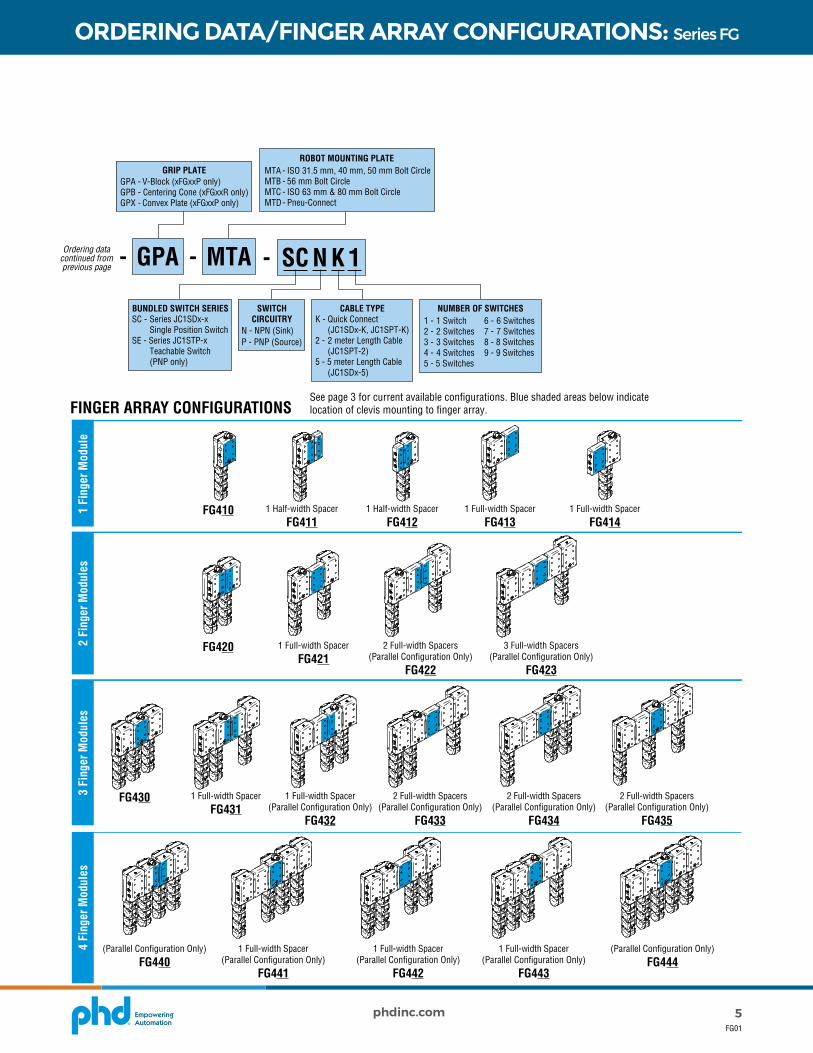
ORDERING DATA/FINGER ARRAY CONFIGURATIONS: Series FG
1 Fi
nger
Mod
ule
2 Fi
nger
Mod
ules
3 Fi
nger
Mod
ules
4 Fi
nger
Mod
ules
FG410 1 Half-width SpacerFG411
1 Half-width SpacerFG412
1 Full-width SpacerFG413
1 Full-width SpacerFG414
FG420 1 Full-width SpacerFG421
2 Full-width Spacers(Parallel Configuration Only)
FG422
3 Full-width Spacers(Parallel Configuration Only)
FG423
FG430 1 Full-width SpacerFG431
1 Full-width Spacer(Parallel Configuration Only)
FG432
2 Full-width Spacers(Parallel Configuration Only)
FG433
(Parallel Configuration Only)FG440
1 Full-width Spacer(Parallel Configuration Only)
FG441
1 Full-width Spacer(Parallel Configuration Only)
FG442
1 Full-width Spacer(Parallel Configuration Only)
FG443
(Parallel Configuration Only)FG444
2 Full-width Spacers(Parallel Configuration Only)
FG434
2 Full-width Spacers(Parallel Configuration Only)
FG435
B P x - -
-
20 FG 4 10
GPA - MTA
C 5 2FG - -
TO ORDER SPECIFY:Product, Action, Finger Array Orientation, Hub, Design No., Size, Number of Finger Arrays, Finger Array Specification Fields, Grip Plate, Robot Mounting Plate, and Switches.
PRODUCT
DESIGN NO.*5 - Metric
A - High Mount, Inward Facing Grip B - Low Mount, Inward Facing Grip C - High Mount, Inward Grip, With Clevis Spacer D - Low Mount, Inward Grip, With Clevis Spacer E - High Mount, Outward Facing Grip F - Low Mount, Outward Facing Grip G - High Mount, Outward Grip, With Clevis Spacer H - Low Mount, Outward Grip, With Clevis Spacer BLANK - No Hub Attachment
FINGER ARRAY ORIENTATION
FINGER ARRAY SPECIFICATION FIELD (See Note 3)See diagrams on next page for possible combinations.
R - 3-Clevis Radial Hub P - 2-Clevis Parallel Hub BLANK - No Hub
HUB (See Note 1)
NOTES:1) If “Finger Array Orientation” field is blank, “Hub” field must also be blank.2) 1 Array if “Hub” field is blank. 2 Arrays for xFGxxP. 3 Arrays for xFGxxR.3) Finger Array Specification Field - Number of fields should match number of finger arrays. Example: FGCBP-5-20x2-FG410-FG410-GPA-MTA-SCNK14) *Design number dictates imperial or metric mountings. Ports are interchangeable.5) Corrosion-resistant fasteners standard.
Configurable FLEXION Finger Gripper System
C - Single Acting, Block Mounting
ACTION
GPA - V-Block (xFGxxP only)GPB - Centering Cone (xFGxxR only)GPX - Convex Plate (xFGxxP only)
GRIP PLATE MTA - ISO 31.5 mm, 40 mm, 50 mm Bolt CircleMTB - 56 mm Bolt CircleMTC - ISO 63 mm & 80 mm Bolt CircleMTD - Pneu-Connect
ROBOT MOUNTING PLATE
20 - 0.800 Wide Segments
SIZE
1 - 1 Array2 - 2 Arrays3 - 3 Arrays
NUMBER OF FINGER ARRAYS
(See Note 2)
FINGER STYLEFG - Round Tip
NUMBER OF FINGER SEGMENTS
4 - 4 Segments
ARRAY CONFIGURATION(See configuration
diagrams)
FG 4 10
FINGER STYLEFG - Round Tip
NUMBER OF FINGER SEGMENTS
4 - 4 Segments
- SC N K 1
BUNDLED SWITCH SERIESSC - Series JC1SDx-x Single Position SwitchSE - Series JC1STP-x Teachable Switch (PNP only)
CABLE TYPEK - Quick Connect (JC1SDx-K, JC1SPT-K)2 - 2 meter Length Cable (JC1SPT-2)5 - 5 meter Length Cable (JC1SDx-5)
1 - 1 Switch2 - 2 Switches3 - 3 Switches4 - 4 Switches5 - 5 Switches
6 - 6 Switches7 - 7 Switches8 - 8 Switches9 - 9 Switches
NUMBER OF SWITCHESSWITCH CIRCUITRY
N - NPN (Sink)P - PNP (Source)
Ordering data continued on
next page
Ordering data continued from previous page
FINGER ARRAY SPECIFICATION FIELD (See Note 3)See diagrams on next page for possible combinations.
ARRAY CONFIGURATION(See configuration
diagrams)
Gray shaded codes are not available at this time. Contact PHD for availability.
FINGER ARRAY CONFIGURATIONSSee page 3 for current available configurations. Blue shaded areas below indicate location of clevis mounting to finger array.

6 phdinc.comFG01
ORDERING: Developer Solutions Kits
RADIAL SOLUTIONS KIT BASE NO. CONTENTS
COMPONENTS91663-03-014
(Small Kit) 91663-06-014 (Medium Kit)
91663-9-014 (Large Kit)
QUANTITY QUANTITY QUANTITYRadial Hub 1 1 1Clevis (Standard Mount) 3 3 3Clevis (Reverse Mount) 3 3 3Finger Module 3 6 9Spacer, Full Width — 3 3Tierod Kit - 2 Finger Module Positions — 3 3Tierod Kit - 3 Finger Module Positions — 3 3Grip Plate, Centering Cone 1 1 1
Each Flexion Developer Solutions Kit will include all required fasteners and hardware to assemble the complete gripper assemblies.
FLEXION DEVELOPER SOLUTIONS KITSThe Developer Solutions Kits contain the parts to build a large variety of combinations, based on the type and size of kit purchased. There are either Parallel or Radial kit types and each have three options for quantity of fingers and related parts. These kits provide the ability to test different gripper configurations with your applications to determine the optimal setup needed.
-01 0191662-04-014 -
TO ORDER SPECIFY:Base No., Robot Mounting Plate, Switches and Valve.
PARALLEL SOLUTIONS KIT BASE NO. (See kit contents listed below) ROBOT MOUNTING PLATE
01 - ISO 31.5 mm, 40 mm, 50 mm Bolt Circle 02 - 56 mm Bolt Circle03 - ISO 63 mm & 80 mm Bolt Circle
01 - JC1SDN-K 02 - JC1SDN-503 - JC1SDP-K04 - JC1SDP-505 - JC1STP-K06 - JC1STP-5
SWITCHESQuantities included match
number of Finger Modules per Base No.
91662-04-014 - Small, 4 Finger Modules 91662-06-014 - Medium, 6 Finger Modules91662-10-014 - Large, 10 Finger Modules
RADIAL SOLUTIONS KIT BASE NO. (See kit contents listed below)
91663-03-014 - Small, 3 Finger Modules 91663-06-014 - Medium, 6 Finger Modules91663-09-014 - Large, 9 Finger Modules
- 1
(See page 16 for switch details)
VALVE0 - No Valve1 - Valve
PARALLEL SOLUTIONS KIT BASE NO. CONTENTS
COMPONENTS91662-04-014
(Small Kit) 91662-06-014 (Medium Kit)
91662-10-014 (Large Kit)
QUANTITY QUANTITY QUANTITYParallel Hub 1 1 1Clevis (Standard Mount) 2 2 2Clevis (Reverse Mount) 2 2 2Finger Module 4 6 10Spacer, Full Width 6 6 6Spacer, Half Width 2 2 2Tierod Assortment Kit 2 2 2Grip Plate, V-Block 1 1 1Grip Plate, Convex 1 1 1
Each Flexion Developer Solutions Kit will include all required fasteners and hardware to assemble the complete gripper assemblies.
7phdinc.comFG01
ENGINEERING DATA: Series FG
SPECIFICATIONS IMPERIAL METRICOPERATING PRESSURE 5 psi* min to 120 psi max 0.4 bar* min to 8.3 bar maxMAX. OPERATING TEMPERATURE 180°F 82°CMIN. OPERATING TEMPERATURE -20°F -29°CRATED LIFE 5 million cyclesLUBRICATION Factory lubricated for rated life
NOTE: *Unit may not fully articulate at 5 psi [0.4 bar] operating pressure.
GRIPPING SYSTEM COMPONENTWEIGHT
lb kgFINGER MODULE 0.45 0.203-CLEVIS RADIAL HUB 0.77 0.352-CLEVIS PARALLEL HUB 0.69 0.31CLEVIS 0.17 0.08CLEVIS LINK 0.26 0.12FULL SPACER BLOCK 0.19 0.09HALF SPACER BLOCK 0.09 0.04
TIE-ROD SETS (REQUIRED TO ASSEMBLE FINGER GROUPS TOGETHER)
1.5 FINGER 0.04 0.022 FINGER 0.05 0.023 FINGER 0.07 0.034 FINGER 0.08 0.04
NOTE: Weight values include weights of associated fasteners, but not interconnecting air tubing and fittings.
FINGER FULL ARTICULATION TRAVEL
MAXIMUM GRIP FORCE AT FINGER TIP AT 5 psi [0.4 bar]
MINIMUM GRIP FORCE AT FINGER TIP AT
120 psi [8.2 bar]
ARTICULATION TIME AT 87 psi [6 bar]
LATERAL MOVEMENT
LONGITUDINAL MOVEMENT
FULL FLEXION
FULL EXTENSION
in mm in mm lb N lb N ms2.20 55.9 2.95 75 1.0 4.4 13.9 62.1 25 130
NOTE: Grip forces assume 0.5 coefficient of friction between finger tip and workpiece.
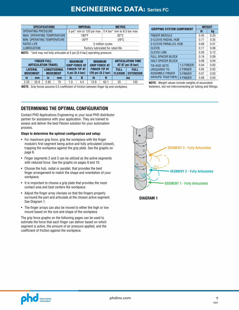
DETERMINING THE OPTIMAL CONFIGURATION Contact PHD Applications Engineering or your local PHD distributor partner for assistance with your application. They are trained to assess and deliver the best Flexion solution for your automation process.
Steps to determine the optimal configuration and setup:
• For maximum grip force, grip the workpiece with the finger module’s first segment being active and fully articulated (closed), trapping the workpiece against the grip plate. See the graphs on page 8.
• Finger segments 2 and 3 can be utilized as the active segments with reduced force. See the graphs on pages 9 and 10.
• Choose the hub, radial or parallel, that provides the best finger arrangement to match the shape and orientation of your workpiece.
• It is important to choose a grip plate that provides the most contact area and best centers the workpiece.
• Adjust the finger array clevises so that the fingers properly surround the part and articulate at the chosen active segment. See Diagram 1.
• The finger arrays can also be moved to either the high or low mount based on the size and shape of the workpiece.
The grip force graphs on the following pages can be used to estimate the force that each finger can deliver based on which segment is active, the amount of air pressure applied, and the coefficient of friction against the workpiece.
SEGMENT 1 - Fully Articulated
SEGMENT 2 - Fully Articulated
SEGMENT 3 - Fully Articulated
DIAGRAM 1

8 phdinc.comFG01
ENGINEERING DATA: Series FG
DETERMINING PIVOT TO SEGMENT CONTACT POSITION DISTANCE
Tota
l Grip
For
ce l
b [N
]
Tota
l Grip
For
ce l
b [N
]
Pivot to Segment Contact Position Distance in [mm]
With 0.2 Coefficient of Friction Against Workpiece
Tota
l Grip
For
ce l
b [N
]
With 0.4 Coefficient of Friction Against Workpiece
Tota
l Grip
For
ce l
b [N
]
With 0.6 Coefficient of Friction Against Workpiece
With 0.2 Coefficient of Friction Against Workpiece
Air Pressure 5 to 20 psi [0.3 to 1.4 bar] Air Pressure 60 to 120 psi [4 to 8 bar]
With 0.4 Coefficient of Friction Against Workpiece
With 0.6 Coefficient of Friction Against Workpiece
0.3 0.4 0.5 0.6 0.7 0.8 0.9 1.0 [7.6] [10.2] [12.7] [15.2] [17.8] [20.3] [22.9] [25.4]
Pivot to Segment Contact Position Distance in [mm]
0.3 0.4 0.5 0.6 0.7 0.8 0.9 1.0 [7.6] [10.2] [12.7] [15.2] [17.8] [20.3] [22.9] [25.4]
Pivot to Segment Contact Position Distance in [mm]
0.3 0.4 0.5 0.6 0.7 0.8 0.9 1.0 [7.6] [10.2] [12.7] [15.2] [17.8] [20.3] [22.9] [25.4]
Pivot to Segment Contact Position Distance in [mm]
0.3 0.4 0.5 0.6 0.7 0.8 0.9 1.0 [7.6] [10.2] [12.7] [15.2] [17.8] [20.3] [22.9] [25.4]
Pivot to Segment Contact Position Distance in [mm]
0.3 0.4 0.5 0.6 0.7 0.8 0.9 1.0 [7.6] [10.2] [12.7] [15.2] [17.8] [20.3] [22.9] [25.4]
Pivot to Segment Contact Position Distance in [mm]
0.3 0.4 0.5 0.6 0.7 0.8 0.9 1.0 [7.6] [10.2] [12.7] [15.2] [17.8] [20.3] [22.9] [25.4]
30 [133]
25 [111]
20 [89]
15 [67]
10 [44]
5 [22]
5.0 [22]
4.5 [20]
4.0 [18]
3.5 [16]
3.0 [13]
2.5 [11]
2.0 [9]
1.5 [7]
1.0 [4]
0.5 [2]
0 [0]
Tota
l Grip
For
ce l
b [N
]
4.0 [18]
3.5 [16]
3.0 [13]
2.5 [11]
2.0 [9]
1.5 [7]
1.0 [4]
0.5 [2]
0 [0]
Tota
l Grip
For
ce l
b [N
]
3.0 [13]
2.5 [11]
2.0 [9]
1.5 [7]
1.0 [4]
0.5 [2]
0 [0]
25 [111]
20 [89]
15 [67]
10 [44]
5 [22]
0 [0]
20 [89]
18 [80]
16 [71]
14 [62]
12 [53]
10 [44]
8 [36]
6 [27]
4 [18]
2 [9]
GRIP FORCE - SEGMENT 1 ACTIVE
60 psi [4 bar] No Articulation60 psi [4 bar] Full Articulation
87 psi [6 bar] No Articulation87 psi [6 bar] Full Articulation
120 psi [8 bar] No Articulation120 psi [8 bar] Full Articulation
5 psi [0.3 bar] No Articulation5 psi [0.3 bar] Full Articulation
10 psi [0.7 bar] No Articulation10 psi [0.7 bar] Full Articulation
20 psi [1.4 bar] No Articulation20 psi [1.4 bar] Full Articulation
FINGER GRIP FORCE - SEGMENT 1 ACTIVEGrip force varies with the amount of friction between the finger and workpiece. Graph values below assume that the coefficient of friction listed on each graph applies between the finger and workpiece.
Grip force varies with the amount of finger articulation and the distance between the finger segment pivot and the position of the contact between the segment and workpieces. The diagram to the right illustrates how to determine pivot to segment contact position distance which is used in the appropriate graph below.
Actual grip forces may be higher than those shown depending on the degree that fingers encapsulate the gripped workpiece.
35°
PIVOT TO SEGMENTCONTACT DISTANCE WITH FULL ARTICULATION
SEGMENT 1 ACTIVE
WORKPIECE GRIPPED WITH FULL FIRST SEGMENT ARTICULATION

9phdinc.comFG01
ENGINEERING DATA: Series FG
DETERMINING PIVOT TO SEGMENT CONTACT POSITION DISTANCE
With 0.2 Coefficient of Friction Against Workpiece
With 0.4 Coefficient of Friction Against Workpiece
With 0.6 Coefficient of Friction Against Workpiece
With 0.2 Coefficient of Friction Against Workpiece
With 0.4 Coefficient of Friction Against Workpiece
With 0.6 Coefficient of Friction Against Workpiece
Pivot to Segment Contact Position Distance in [mm]
0.3 0.5 0.7 0.9 1.1 1.3 1.5 [7.6] [12.7] [17.8] [22.9] [27.9] [33.0] [38.1]
Pivot to Segment Contact Position Distance in [mm]
0.3 0.5 0.7 0.9 1.1 1.3 1.5 [7.6] [12.7] [17.8] [22.9] [27.9] [33.0] [38.1]
Pivot to Segment Contact Position Distance in [mm]
0.3 0.5 0.7 0.9 1.1 1.3 1.5 [7.6] [12.7] [17.8] [22.9] [27.9] [33.0] [38.1]
Pivot to Segment Contact Position Distance in [mm]
0.3 0.5 0.7 0.9 1.1 1.3 1.5 [7.6] [12.7] [17.8] [22.9] [27.9] [33.0] [38.1]
Pivot to Segment Contact Position Distance in [mm]
0.3 0.5 0.7 0.9 1.1 1.3 1.5 [7.6] [12.7] [17.8] [22.9] [27.9] [33.0] [38.1]
Pivot to Segment Contact Position Distance in [mm]
0.3 0.5 0.7 0.9 1.1 1.3 1.5 [7.6] [12.7] [17.8] [22.9] [27.9] [33.0] [38.1]
Tota
l Grip
For
ce l
b [N
]30
[133]
25 [111]
20 [89]
15 [67]
10 [44]
5 [22]
0 [0]
Tota
l Grip
For
ce l
b [N
]
5.0 [22]
4.5 [20]
4.0 [18]
3.5 [16]
3.0 [13]
2.5 [11]
2.0 [9]
1.5 [7]
1.0 [4]
0.5 [2]
0 [0]
Tota
l Grip
For
ce l
b [N
]
4.0 [18]
3.5 [16]
3.0 [13]
2.5 [11]
2.0 [9]
1.5 [7]
1.0 [4]
0.5 [2]
0 [0]
Tota
l Grip
For
ce l
b [N
]
3.0 [13]
2.5 [11]
2.0 [9]
1.5 [7]
1.0 [4]
0.5 [2]
0 [0]
Tota
l Grip
For
ce l
b [N
]
25 [111]
20 [89]
15 [67]
10 [44]
5 [22]
0 [0]
Tota
l Grip
For
ce l
b [N
]
18 [80]
16 [71]
14 [62]
12 [53]
10 [44]
8 [36]
6 [27]
4 [18]
2 [9]
60 psi [4 bar] No Articulation60 psi [4 bar] Full Articulation
87 psi [6 bar] No Articulation87 psi [6 bar] Full Articulation
120 psi [8 bar] No Articulation120 psi [8 bar] Full Articulation
5 psi [0.3 bar] No Articulation5 psi [0.3 bar] Full Articulation
10 psi [0.7 bar] No Articulation10 psi [0.7 bar] Full Articulation
20 psi [1.4 bar] No Articulation20 psi [1.4 bar] Full Articulation
Air Pressure 5 to 20 psi [0.3 to 1.4 bar] Air Pressure 60 to 120 psi [4 to 8 bar]
FINGER GRIP FORCE - SEGMENT 2 ACTIVEGrip force varies with the amount of friction between the finger and workpiece. Graph values below assume that the coefficient of friction listed on each graph applies between the finger and workpiece.
Grip force varies with the amount of finger articulation and the distance between the finger segment pivot and the position of the contact between the segment and workpieces. The diagram to the right illustrates how to determine pivot to segment contact position distance which is used in the appropriate graph below.
Actual grip forces may be higher than those shown depending on the degree that fingers encapsulate the gripped workpiece.
35°
PIVOT TO SEGMENTCONTACT DISTANCE WITH FULL ARTICULATION
WORKPIECE GRIPPED WITH FULL FIRST SEGMENT ARTICULATION
SEGMENT 2 ACTIVE

10 phdinc.comFG01
ENGINEERING DATA: Series FG
DETERMINING PIVOT TO SEGMENT CONTACT POSITION DISTANCE
Pivot to Segment Contact Position Distance in [mm]Pivot to Segment Contact Position Distance in [mm]
Pivot to Segment Contact Position Distance in [mm]Pivot to Segment Contact Position Distance in [mm]
Pivot to Segment Contact Position Distance in [mm]Pivot to Segment Contact Position Distance in [mm]
With 0.2 Coefficient of Friction Against WorkpieceWith 0.2 Coefficient of Friction Against Workpiece
With 0.4 Coefficient of Friction Against WorkpieceWith 0.4 Coefficient of Friction Against Workpiece
With 0.6 Coefficient of Friction Against WorkpieceWith 0.6 Coefficient of Friction Against Workpiece
0.3 0.5 0.7 0.9 1.1 1.3 1.5 1.7 [7.6] [12.7] [17.8] [22.9] [27.9] [33.0] [38.1] [43.2]
0.3 0.5 0.7 0.9 1.1 1.3 1.5 1.7 [7.6] [12.7] [17.8] [22.9] [27.9] [33.0] [38.1] [43.2]
0.3 0.5 0.7 0.9 1.1 1.3 1.5 1.7 [7.6] [12.7] [17.8] [22.9] [27.9] [33.0] [38.1] [43.2]
0.3 0.5 0.7 0.9 1.1 1.3 1.5 1.7 [7.6] [12.7] [17.8] [22.9] [27.9] [33.0] [38.1] [43.2]
0.3 0.5 0.7 0.9 1.1 1.3 1.5 1.7 [7.6] [12.7] [17.8] [22.9] [27.9] [33.0] [38.1] [43.2]
0.3 0.5 0.7 0.9 1.1 1.3 1.5 1.7 [7.6] [12.7] [17.8] [22.9] [27.9] [33.0] [38.1] [43.2]
Tota
l Grip
For
ce l
b [N
]
5.0 [22]
4.5 [20]
4.0 [18]
3.5 [16]
3.0 [13]
2.5 [11]
2.0 [9]
1.5 [7]
1.0 [4]
0.5 [2]
0 [0]
Tota
l Grip
For
ce l
b [N
]
4.0 [18]
3.5 [16]
3.0 [13]
2.5 [11]
2.0 [9]
1.5 [7]
1.0 [4]
0.5 [2]
0 [0]
Tota
l Grip
For
ce l
b [N
]
3.0 [13]
2.5 [11]
2.0 [9]
1.5 [7]
1.0 [4]
0.5 [2]
0 [0]
Tota
l Grip
For
ce l
b [N
]
30 [133]
25 [111]
20 [89]
15 [67]
10 [44]
5 [22]
0 [0]
Tota
l Grip
For
ce l
b [N
]
25 [111]
20 [89]
15 [67]
10 [44]
5 [22]
0 [0]
Tota
l Grip
For
ce l
b [N
]
18 [80]
16 [71]
14 [62]
12 [53]
10 [44]
8 [36]
6 [27]
4 [18]
2 [9]
60 psi [4 bar] No Articulation60 psi [4 bar] Full Articulation
87 psi [6 bar] No Articulation87 psi [6 bar] Full Articulation
120 psi [8 bar] No Articulation120 psi [8 bar] Full Articulation
5 psi [0.3 bar] No Articulation5 psi [0.3 bar] Full Articulation
10 psi [0.7 bar] No Articulation10 psi [0.7 bar] Full Articulation
20 psi [1.4 bar] No Articulation20 psi [1.4 bar] Full Articulation
Air Pressure 5 to 20 psi [0.3 to 1.4 bar] Air Pressure 60 to 120 psi [4 to 8 bar]
FINGER GRIP FORCE - SEGMENT 3 ACTIVEGrip force varies with the amount of friction between the finger and workpiece. Graph values below assume that the coefficient of friction listed on each graph applies between the finger and workpiece.
Grip force varies with the amount of finger articulation and the distance between the finger segment pivot and the position of the contact between the segment and workpieces. The diagram to the right illustrates how to determine pivot to segment contact position distance which is used in the appropriate graph below.
Actual grip forces may be higher than those shown depending on the degree that fingers encapsulate the gripped workpiece.
PIVOT TO SEGMENTCONTACT DISTANCE WITH FULL ARTICULATION
WORKPIECE GRIPPED WITH FULL SECOND SEGMENT ARTICULATION
35°
SEGMENT 3 ACTIVE

11phdinc.comFG01
DIMENSIONS: Series FG - Finger Module & Spacers
2X SWITCH SLOTS
1.484[37.7]
M5 x 0.8 -6H DP 0.177 [4.5] PORT
1.625[41.3]
0.335 [8.5]
8X M4 x 0.7 -6H DP 0.315 [8] MOUNTING
THREADS0.813[20.6]
0.375[9.5]
0.875[22.2]
2.500 [63.5]
1.625[41.3] 2.125
[54]
0.780[19.8]
M5 x 0.8 -6H DP 0.177 [4.5] PORT OPP SIDE ALSO SHIPPED PLUGGED
0.280[7.1]
1.313[33.3]
2X TIEROD MOUNTING HOLE
0.511[13]
2.949[74.9]
2.200[55.9]
0.897[22.8]
2.875[73]
6.386[162.2]
All dimensions are reference only unless specifically toleranced.
FULL FINGER WIDTH SPACER
FINGER MODULE
HALF FINGER WIDTH SPACER
2X CLEVIS MOUNTING THDS
1.188M5 x 0.8 -6H DP 0.177 [4.5] PORT OP
SIDE ALSO
2X TIEROD MOUNTING HOLES
1.313[33.3]
0.280[7.11]
1.625[41.28]
2.500[63.5]
4X CLEVIS MOUNTING THDS
2X TIEROD MOUNTING HOLES
M5 x 0.8 -6H DP 0.177 PORT OP
SIDE ALSO0.280[7.11]
0.813[20.64]
2.500[63.5]
12 phdinc.comFG01
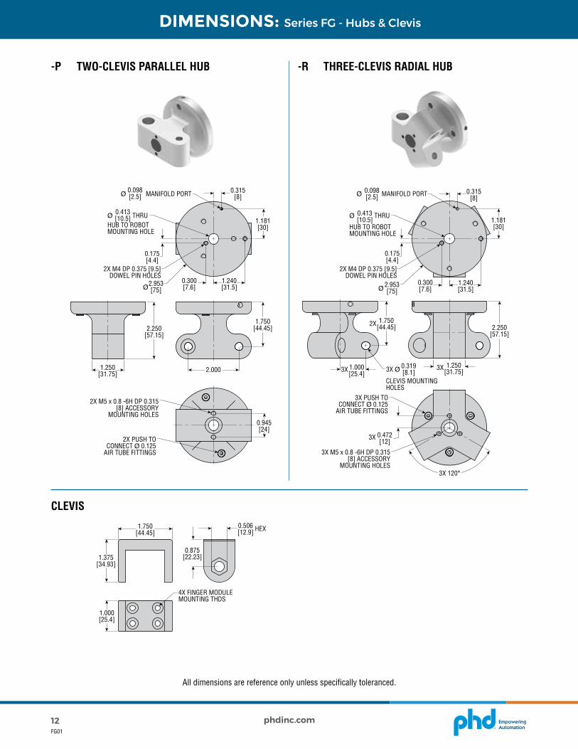
DIMENSIONS: Series FG - Hubs & Clevis
-P TWO-CLEVIS PARALLEL HUB
CLEVIS
-R THREE-CLEVIS RADIAL HUB
All dimensions are reference only unless specifically toleranced.
2.000
0.315 [8]
0.315 [8]
Ø MANIFOLD PORT0.098[2.5] Ø MANIFOLD PORT0.098
[2.5]
1.181[30]
1.181[30]
Ø THRU HUB TO ROBOT MOUNTING HOLE
0.413[10.5] Ø THRU
HUB TO ROBOT MOUNTING HOLE
0.413[10.5]
0.175[4.4]
0.175[4.4]
2X M4 DP 0.375 [9.5] DOWEL PIN HOLES
2X M4 DP 0.375 [9.5] DOWEL PIN HOLES
Ø2.953[75] Ø 2.953
[75]
0.300[7.6]
1.240[31.5]
0.300[7.6]
1.240[31.5]
2.250[57.15]
2.250[57.15]
1.250[31.75]
1.000[25.4]
1.750[44.45]
1.750[44.45]
0.945[24]
2X M5 x 0.8 -6H DP 0.315 [8] ACCESSORY
MOUNTING HOLES
2X PUSH TO CONNECT Ø 0.125
AIR TUBE FITTINGS
3X PUSH TO CONNECT Ø 0.125
AIR TUBE FITTINGS
2X
1.250[31.75]3X
0.472[12]
3X
3X
3X 120°
0.319[8.1]3X Ø
CLEVIS MOUNTING HOLES
3X M5 x 0.8 -6H DP 0.315 [8] ACCESSORY
MOUNTING HOLES
HEX1.750[44.45]
0.875[22.23]
0.506[12.9]
1.375[34.93]
4X FINGER MODULE MOUNTING THDS
1.000[25.4]

13phdinc.comFG01
DIMENSIONS: Series FG - Gripper Plates
-GPA V-BLOCK (xFGxxP only)
-GPB CENTERING CONE (xFGxxR only)
-GPX CONVEX PLATE (xFGxxP only)
All dimensions are reference only unless specifically toleranced.
0.923[23.4]
0.945 [24.0]
120°
A A
SECTION A-A
SECTION A-A
SECTION A-A
3X 0.673 [17.1]
69°A
A
A
A
2X COUNTERBORE Ø 0.368 [9.4]
(SEE A-A FOR DEPTH)
3X COUNTERBORE Ø 0.368 [9.4](SEE A-A FOR DEPTH)
2X COUNTERBORE Ø 0.368 [9.4]
(SEE A-A FOR DEPTH)
0.945 [24.0]
2X 63°
2X 43°
3.000[76.2]
Ø 0.391 [9.9] THRU
2X Ø 0.213 [5] THRU
2X Ø 0.213 [5.4] THRU
3X Ø 0.213 [5] THRU
Ø 0.391 [9.9] THRU
2X 0.713 [18.1]
R 0.125 [3.2]
4.250 [108.0]
Ø 2.000 [50.8]
2.345[59.6]
2X R 0.750 [19.1] 1.500 [38.1]
Ø 3.022 [76.8]
3.000[76.2]
3X 120°1.500[38.1]
0.783[19.9]
120° Ø 2.875 [73.0]
0.945 [24.0]
R2X 0.222
[5.6]
1.994[50.6]
1.250[31.8]
1.000[25.4]
Ø 0.391 [9.9] THRU4.375
[111.1]
0.966[24.5]

14 phdinc.comFG01
DIMENSIONS: Series FG - Robot Mounting Plates
-MTA ISO 31.5 mm, 40 mm, 50 mm BOLT CIRCLE
-MTB 56 mm BOLT CIRCLE
-MTC ISO 63 mm, 80 mm BOLT CIRCLE
All dimensions are reference only unless specifically toleranced.
MANIFOLD PORT
M5 x 0.8 THREADED PORT
M5 x 0.8 THREADED PORT
M5 x 0.8 THREADED PORT R 0.125 [3.1]
4X Ø 6 mm ROBOT DOWEL PIN HOLE
4X Ø 4 mm ROBOT DOWEL PIN HOLE
4X Ø 8 mm ROBOT DOWEL PIN HOLE4X Ø 6 mm ROBOT DOWEL PIN HOLE
4X 6 mm SOCKET HEAD SCREW ROBOT BOLT HOLE
11X 4 mm SOCKET HEAD SCREW ROBOT BOLT CIRCLE
4X 8 mm SOCKET HEAD SCREW ROBOT BOLT CIRCLE
4X 6 mm SOCKET HEAD SCREW ROBOT BOLT CIRCLE
4X 5 mm SOCKET HEAD SCREW ROBOT BOLT HOLE
4X Ø 5 mm ROBOT DOWEL PIN HOLE
12X 45°
Ø 1.240 [31.5]
Ø 1.575 [40.0]
Ø 1.969 [50.0]
Ø 2.205 [56.0]
Ø 3.937 [100.0]
Ø 3.150 [80.0]
Ø 2.480[63.0]
Ø 2.95 [75.0]
Ø 2.953 [75.0]
0.472[12.0]
0.236[6.0]
0.236[6.0]
0.236[6.0]
0.315[8.0]
0.315[8.0]
0.300[7.6]
0.300[7.6]
1.181[30.0]
1.417 [36.0]
0.236[6.0]
0.276[7]
0.300[7.6]
Ø 2.953[75.0]
Ø 2.953[75.0]
Ø 2.953 [75.0]Ø 0.315[8.0]
Ø 2.480[63.0]
( )Ø 1.969 [50.0]
0.175[4.4]
Ø 0.098 [2.5]
MANIFOLD PORT
Ø 0.098 [2.5]
Ø 0.098 [2.5]MANIFOLD PORT
( )Ø 1.575 [40.0]
( )Ø 1.240 [31.5]
1.240 [31.5]
1.240[31.5]
1.240[31.5]
M10 x 1.5 THREADED HOLEHUB TO ROBOT MOUNTING
M10 x 1.5 THREADED HOLE
HUB TO ROBOT MOUNTING
M10 x 1.5 THREADED HOLE HUB TO ROBOT MOUNTING
2X Ø 4 mm DOWEL PIN HOLES
2X Ø 4 mm DOWEL PIN HOLES
2X Ø 4 mm DOWEL PIN HOLES
0.472[12.0]
0.175[4.4]
0.175[4.4]
1.181 [30.0]
1.181[30.0]
2.135[54.2]
0.571 [14.5]
1.575 [40.0]
1.1 [28.0]
0.748[19.0]
0.394[10.0]
1.909[48.5]
1.417 [36.0]
4X 67.5°
4X 45°
8X 45°
3X 22.5°
0.315[8.0]
GRIPPER MOUNTING M10 x 1.5, FASTENER
SUPPLIED WITH GRIPPER
MOUNTING TO ROBOT CONFORMS TO INTERFACE DESIGNATION ISO 9409-1-50-4-M6
LOCATING PINS SUPPLIED WITH
GRIPPER
SEALING O-RING SUPPLIED WITH GRIPPER
M8 RIGHT ANGLE FEMALE
CONNECTOR, 8 POLES
MANIFOLD PORT
M5 x 0.8 THREADED PORT
M5 x 0.8 THREADED PORT
M5 x 0.8 THREADED PORT R 0.125 [3.1]
4X Ø 6 mm ROBOT DOWEL PIN HOLE
4X Ø 4 mm ROBOT DOWEL PIN HOLE
4X Ø 8 mm ROBOT DOWEL PIN HOLE4X Ø 6 mm ROBOT DOWEL PIN HOLE
4X 6 mm SOCKET HEAD SCREW ROBOT BOLT HOLE
11X 4 mm SOCKET HEAD SCREW ROBOT BOLT CIRCLE
4X 8 mm SOCKET HEAD SCREW ROBOT BOLT CIRCLE
4X 6 mm SOCKET HEAD SCREW ROBOT BOLT CIRCLE
4X 5 mm SOCKET HEAD SCREW ROBOT BOLT HOLE
4X Ø 5 mm ROBOT DOWEL PIN HOLE
12X 45°
Ø 1.240 [31.5]
Ø 1.575 [40.0]
Ø 1.969 [50.0]
Ø 2.205 [56.0]
Ø 3.937 [100.0]
Ø 3.150 [80.0]
Ø 2.480[63.0]
Ø 2.95 [75.0]
Ø 2.953 [75.0]
0.472[12.0]
0.236[6.0]
0.236[6.0]
0.236[6.0]
0.315[8.0]
0.315[8.0]
0.300[7.6]
0.300[7.6]
1.181[30.0]
1.417 [36.0]
0.236[6.0]
0.276[7]
0.300[7.6]
Ø 2.953[75.0]
Ø 2.953[75.0]
Ø 2.953 [75.0]Ø 0.315[8.0]
Ø 2.480[63.0]
( )Ø 1.969 [50.0]
0.175[4.4]
Ø 0.098 [2.5]
MANIFOLD PORT
Ø 0.098 [2.5]
Ø 0.098 [2.5]MANIFOLD PORT
( )Ø 1.575 [40.0]
( )Ø 1.240 [31.5]
1.240 [31.5]
1.240[31.5]
1.240[31.5]
M10 x 1.5 THREADED HOLEHUB TO ROBOT MOUNTING
M10 x 1.5 THREADED HOLE
HUB TO ROBOT MOUNTING
M10 x 1.5 THREADED HOLE HUB TO ROBOT MOUNTING
2X Ø 4 mm DOWEL PIN HOLES
2X Ø 4 mm DOWEL PIN HOLES
2X Ø 4 mm DOWEL PIN HOLES
0.472[12.0]
0.175[4.4]
0.175[4.4]
1.181 [30.0]
1.181[30.0]
2.135[54.2]
0.571 [14.5]
1.575 [40.0]
1.1 [28.0]
0.748[19.0]
0.394[10.0]
1.909[48.5]
1.417 [36.0]
4X 67.5°
4X 45°
8X 45°
3X 22.5°
0.315[8.0]
GRIPPER MOUNTING M10 x 1.5, FASTENER
SUPPLIED WITH GRIPPER
MOUNTING TO ROBOT CONFORMS TO INTERFACE DESIGNATION ISO 9409-1-50-4-M6
LOCATING PINS SUPPLIED WITH
GRIPPER
SEALING O-RING SUPPLIED WITH GRIPPER
M8 RIGHT ANGLE FEMALE
CONNECTOR, 8 POLES

15phdinc.comFG01
DIMENSIONS: Series FG - Robot Mounting Plates
-MTD PNEU-CONNECT
All dimensions are reference only unless specifically toleranced.
MANIFOLD PORT
M5 x 0.8 THREADED PORT
M5 x 0.8 THREADED PORT
M5 x 0.8 THREADED PORT R 0.125 [3.1]
4X Ø 6 mm ROBOT DOWEL PIN HOLE
4X Ø 4 mm ROBOT DOWEL PIN HOLE
4X Ø 8 mm ROBOT DOWEL PIN HOLE4X Ø 6 mm ROBOT DOWEL PIN HOLE
4X 6 mm SOCKET HEAD SCREW ROBOT BOLT HOLE
11X 4 mm SOCKET HEAD SCREW ROBOT BOLT CIRCLE
4X 8 mm SOCKET HEAD SCREW ROBOT BOLT CIRCLE
4X 6 mm SOCKET HEAD SCREW ROBOT BOLT CIRCLE
4X 5 mm SOCKET HEAD SCREW ROBOT BOLT HOLE
4X Ø 5 mm ROBOT DOWEL PIN HOLE
12X 45°
Ø 1.240 [31.5]
Ø 1.575 [40.0]
Ø 1.969 [50.0]
Ø 2.205 [56.0]
Ø 3.937 [100.0]
Ø 3.150 [80.0]
Ø 2.480[63.0]
Ø 2.95 [75.0]
Ø 2.953 [75.0]
0.472[12.0]
0.236[6.0]
0.236[6.0]
0.236[6.0]
0.315[8.0]
0.315[8.0]
0.300[7.6]
0.300[7.6]
1.181[30.0]
1.417 [36.0]
0.236[6.0]
0.276[7]
0.300[7.6]
Ø 2.953[75.0]
Ø 2.953[75.0]
Ø 2.953 [75.0]Ø 0.315[8.0]
Ø 2.480[63.0]
( )Ø 1.969 [50.0]
0.175[4.4]
Ø 0.098 [2.5]
MANIFOLD PORT
Ø 0.098 [2.5]
Ø 0.098 [2.5]MANIFOLD PORT
( )Ø 1.575 [40.0]
( )Ø 1.240 [31.5]
1.240 [31.5]
1.240[31.5]
1.240[31.5]
M10 x 1.5 THREADED HOLEHUB TO ROBOT MOUNTING
M10 x 1.5 THREADED HOLE
HUB TO ROBOT MOUNTING
M10 x 1.5 THREADED HOLE HUB TO ROBOT MOUNTING
2X Ø 4 mm DOWEL PIN HOLES
2X Ø 4 mm DOWEL PIN HOLES
2X Ø 4 mm DOWEL PIN HOLES
0.472[12.0]
0.175[4.4]
0.175[4.4]
1.181 [30.0]
1.181[30.0]
2.135[54.2]
0.571 [14.5]
1.575 [40.0]
1.1 [28.0]
0.748[19.0]
0.394[10.0]
1.909[48.5]
1.417 [36.0]
4X 67.5°
4X 45°
8X 45°
3X 22.5°
0.315[8.0]
GRIPPER MOUNTING M10 x 1.5, FASTENER
SUPPLIED WITH GRIPPER
MOUNTING TO ROBOT CONFORMS TO INTERFACE DESIGNATION ISO 9409-1-50-4-M6
LOCATING PINS SUPPLIED WITH
GRIPPER
SEALING O-RING SUPPLIED WITH GRIPPER
M8 RIGHT ANGLE FEMALE
CONNECTOR, 8 POLES

9009 Clubridge DriveFort Wayne, Indiana 46809Ph (260) 747-6151 phdinc.com • [email protected]
Zum Carl-Alexander-Park 652499 Baesweiler, GermanyTel. +49 (0)2401-619 77 0phdinc.com • [email protected]
EmpoweringAutomation
SPECIFICATIONS JC1STP-x
OPERATING PRINCIPLE Programmable Magnetic Field Characterization
INPUT VOLTAGE 12-30 VDCNUMBER & TYPE OF OUTPUTS Two PNP (Source), separately adjustableOUTPUT CURRENT 100 mA max., Short Circuit ProtectionVOLTAGE DROP ≤ 2.2 VDCSWITCH BURDEN ≤ 15 mAENVIRONMENTAL IP67OPERATING TEMPERATURE -20° to 75°CTYP. DETECTION AREA 0-50 mm
PART NO. DESCRIPTIONJC1STP-2 PNP (Source) Solid State, 12-30 VDC, 2 meter cableJC1STP-K PNP (Source) Solid State, 12-30 VDC, Quick Connect
MATCHING CORDSETPART NO. DESCRIPTION
81284-1-001 M8, 4 pin, Straight Female Connector, 5 meter cable
-SC OPTIONThe JC1SD Solid State Switches are offered in 10–30 VDC current sinking (NPN) and current sourcing (PNP) versions for simple interfacing to system controllers. Solid state sensing provides for longest life and most reliable operation. JC1SD are available in cabled (5 meter) or quick connect versions.
SPECIFICATIONS JC1xDP-x JC1xDN-xOPERATING PRINCIPLE Solid State Detection of Moving MagnetINPUT VOLTAGE 10-30 VDCOUTPUT TYPE PNP (Source) NPN (Sink)OUTPUT CURRENT 100 mA max., Short Circuit ProtectionVOLTAGE DROP ≤ 2.5 VDCSWITCH BURDEN ≤ 8 mAENVIRONMENTAL IP67OPERATING TEMPERATURE -30° to 80°C
PART NO. DESCRIPTIONJC1SDP-5 PNP (Source), Axial Sensing, 5 meter cableJC1SDP-K PNP (Source), Axial Sensing, Quick ConnectJC1SDN-5 NPN (Sink), Axial Sensing, 5 meter cableJC1SDN-K NPN (Sink), Axial Sensing, Quick Connect
MATCHING CORDSETSPART NO. DESCRIPTION63549-02 M8, 3 pin, Straight Female Connector, 2 meter cable63549-05 M8, 3 pin, Straight Female Connector, 5 meter cable
-SE OPTIONJC1ST Teachable Switches feature two programmable outputs. Since each switch provides two outputs, the Flexion features two switch slots providing up to four outputs by using two switches. Offered in 12–30 VDC current sourcing (PNP) version only with integrated protection circuitry including short circuit protection.
OPTIONS: Switches
9/21 11352© Copyright 2021, by PHD, Inc. All Rights Reserved. Printed in the U.S.A.
Sxxxx BUNDLED SWITCH OPTIONS
These options conveniently provide switches with additional hardware if required. Series JC1SDx-x single position and inductive proximity switches are available as NPN or PNP. Series JC1STP-x teachable switch is available as PNP only. Connection method may also be specified along with quantity of up to nine switches.
Each Series FG Flexion is sensor ready and has two 4 mm slots for optional JC1 switches for the sensing of finger flex position such as “part gripped”, “no part”, or “starting position.”
All JC1 switches have an LED indicator for convenient setting and troubleshooting. They are rated at IP67 Environmental Protection with a polyurethane (PUR) jacketed cable. Additionally, they feature integrated protection circuitry including short circuit protection, and improved switch hysteresis and magnetic response uniformity.
- Sx x x x
BUNDLED SWITCH SERIESSC - Series JC1SDx-x Single Position SwitchSE - Series JC1STP-x Teachable Switch (PNP only)
CABLE TYPEK - Quick Connect (JC1SDx-K, JC1SPT-K)2 - 2 meter Length Cable (JC1SPT-2)5 - 5 meter Length Cable (JC1SDx-5)
SWITCH BUNDLE OPTION CODE
NUMBER OF SWITCHES
1 - 1 Switch2 - 2 Switches3 - 3 Switches4 - 4 Switches5 - 5 Switches6 - 6 Switches7 - 7 Switches8 - 8 Switches9 - 9 Switches
SWITCH CIRCUITRY
N - NPN (Sink)P - PNP (Source)