
GRID CONNECTED PV POWER GENERATING - ijerst · GRID CONNECTED PV POWER GENERATING ... in...
15
Transcript of GRID CONNECTED PV POWER GENERATING - ijerst · GRID CONNECTED PV POWER GENERATING ... in...

297
Int. J. Engg. Res. & Sci. & Tech. 2015 xxxxxxxxxxxxxxxxxxxxxxxx, 2015
This article can be downloaded from http://www.ijerst.com/RASET-2015.php#1
GRID CONNECTED PV POWER GENERATING
SYSTEM USING CUK CONVERTER AND
TRANSFORMER LESS H5 INVERTER
R R Rubia Gandhi1* and J Karthika2
This paper presents the PI controller based CUK converter and transformer less H5 inverter forgrid connected photovoltaic power generating system. For the maximum power point trackingof the photovoltaic system, P & O based algorithm has been implemented. The Pi controller forthe CUK MPPT scheme shows a regulated output in variable load conditions. A classical H-bridge inverter topology with extra fifth switch has been used to connect the single phase grid.For the traditional grid connected PV inverter system, a transformer is utilized to provide thegalvanic isolation between the grid and PV system. But Common mode leakage current increasesdue to the removal of the transformer from the system. Here, this transformer less H5 inverteris used for the proposed system which suppresses the common mode leakage current therebyimproving the power conversion efficiency and decreases the grid current distortion. The removalof the transformer from the grid tied PV inverter system will give an improvement in the efficiencyfactor and reduces the cost of the system. The performance of the proposed system is testedin MATLAB/SIMULINK software and the simulation results are included for the effectivedemonstration of the converter and inverter efficiency. The results of the grid voltage and gridcurrent have been analyzed and the total harmonic distortion of the PV inverter system hasbeen verified.
*Corresponding Author: R R Rubia Gandhi � [email protected]
1 Department of Electrical and Electronics Engineering, Sri Krishna College of Engineering and Technology, Kuniamuthur, Coimbatore,India.
Int. J. Engg. Res. & Sci. & Tech. 2015
Research Paper
INTRODUCTION
Due to the increase in demand on electricity, and
the crisis of conventional sources, the photovoltaic
(PV) energy is emerging more now. It also
becomes a promising alternative as it is
omnipresent, freely available, environment
friendly, and has less operational and
maintenance costs. The photovoltaic modules are
used for both grid-connected power generation
and off-grid power generation for remote areas
and developing countries. Since the demand of
PV generation systems seems to be increased
for both standalone and grid-connected modes
of PV systems there is a need for an efficient
maximum power point tracking (MPPT) technique
that is expected to track the peak power point at
all environmental conditions and then force the
PV system to operate at that MPP point. MPPT is
an essential component of PV systems.
ISSN 2319-5991 www.ijerst.com
Special Issue, Vol. 1, No. 2, April 2015
2nd National Conference on ‘‘Recent Advances in Science,
Engineering&Technologies’’ RASET-2015
© 2015 IJERST. All Rights Reserved
322
Int. J. Engg. Res. & Sci. & Tech. 2015 N Meyyarasu et al., 2015
This article can be downloaded from http://www.ijerst.com/RASET-2015.php#1
The selection of a proper dc–dc converter playsan important role for maximum power pointtracking (MPPT) operation. The criteria forphotovoltaic (PV) converter selection depend onmany factors, such as cost, efficiency, flexibility,and energy flow. In this case, the flexibilityrepresents the ability of the converter to maintainthe output with the input varying, while the energyflow is assured by the continuous current of theconverter. Among known converters, the SEPIC,conventional buck–boost, and CUK convertershave the ability to step up and step down the inputvoltage. Hence, this converter can transfer energyfor all irradiation levels. Another desirable featureis continuous output current, which allowsconverter output parallel connection, orconversion to a voltage source with minimalcapacitance.
and PV array effect. Unlike a buck–boostconverter, the SEPIC has a non-inverted output,and it uses a series capacitor to isolate input fromoutput [1]. The buck and buck–boost convertershave discontinuous input current, which causesmore power loss due to input switching. The boostconverter usually has higher efficiency than theSEPIC; however, its output voltage is alwayslarger than the input, which causes inflexibility inmaximum power extraction. Both the SEPIC andthe CUK converter provide the choice to haveeither higher or lower output voltage comparedto the input voltage. Furthermore, they havecontinuous input current and better efficiencycompared to buck–boost and fly-back converters[2]. There is no general agreement in the literatureon which one of the two converters is better, i.e.,the SEPIC or the CUK [3]–[10]. This paper seeksto use the CUK converter.
The MPPT algorithm represents optimal loadfor PV array, producing opportune voltage for theload. The PV panel yields exponential curves forcurrent and voltage, where the maximum poweroccurs at the curve’s mutual knee [11], [12]. Theapplied MPPT uses a type of control and logic tolook for the knee, which in turn allows the SEPICconverter to extract the maximum power fromthe PV array. The tracking method used, i.e.,perturb and observe (P&O) [13], [14], provides anew reference signal for the controller and extractsthe maximum power from the PV array.
Among different intelligent controllers, theconventional PI controller gives a better response.It takes the advantage of both the P-action and I-action. The advantages are faster response dueto the P-action and the zero steady state errordue to the I-action. By increasing or decreasingthe gain values of the PI controller, the satisfactoryresponse is obtained for any type control either it
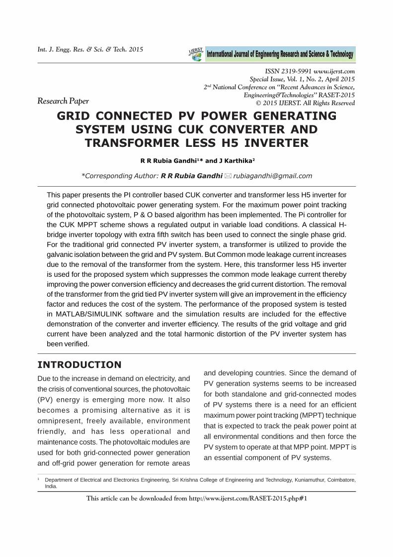
Figure 1: Block diagram of the gridtied power system
The buck or boost converters are notpreferable, due to the lack of output voltageflexibility. For example, for PV system batterycharging, both buck and boost converters areunable to charge the battery continuously withMPPT operation because the power–voltagecurve changes with irradiation level, and hence,the voltage corresponding to maximum powerchanges. There are many factors that can beconsidered for proposing the dc–dc converters,such as input/output energy flow, cost, flexibility,
323
Int. J. Engg. Res. & Sci. & Tech. 2015 N Meyyarasu et al., 2015
This article can be downloaded from http://www.ijerst.com/RASET-2015.php#1
is machine side or converter-inverter side. Thesettling period of the controlling system achievesa faster response by varying the proportional gainconstant. Simultaneously the transient responseof the system can also be improved. The outputresponse of the converter and the inverter iscontrolled in a better way so as to improve theefficiency of the system. A PI controller basedCUK converter is sued so that the overall controlsystem can always provide maximum powertransfer from the PV array to the inverter side, inspite of the unpredictable weather conditions. Thispaper presents a PI-based MPPT operation ofthe CUK converter for PV inverter applications.As the proposed method always transfersmaximum power from PV arrays to the inverterside, it optimizes the number of PV modules. ThePI controller for the CUK MPPT scheme showshigh precision in current transition and keeps thevoltage without any changes, in the variable-loadcase, represented in small steady-state error andsmall overshoot. As the H5-inverter is used in aPV system, PI controller is employed for moreaccurate output sine wave, higher dynamicperformance under rapidly varying atmosphericmilieu exploiting maximum power effectively, andimproved THD with conventional PI-controlledconverters.
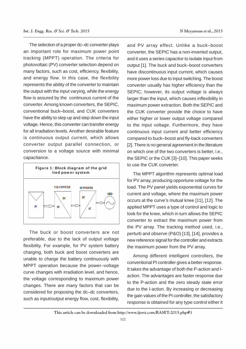
PHOTOVOLTAIC SYSTEMPV cell is the basic device for the photovoltaicsystem.This PV cell is similar to the PN jucntiondiode.It is made of the semiconductor materialeither with P-type, N-type silicon or withgermanium. A photovoltaic system convertssunlight into electricity.Each photovoltaic cells aregrouped to form panels. Panels can be groupedto form large photovoltaic modules.The modulesare grouped to form the large photovoltaic
arrays.And there are two electrodes which areplaced apart which constitutes the two terminlasof the array.
The output of the PV panel is not constant, itis a varying one. This is due to the variation of thetemperature and irradiation levels.For a day theintensity of the sun light keeps on the changing,this results in various irradiation levels. And alsothe temperature of the PV panel varies due to theuneven heating of the panel. This results indecrease in the power output of the PV panel. Soit is necessary to track the maximum power fromthe PV panel in all the load conditions. This leadsto give a maximum efficiency from thephotovoltaic system.
The electricity available at the terminals of aphotovoltaic array may directly feed small loadssuch as lighting system and DC motors.Someapplicaions require electronic converters toprocess the electricity from the photovoltaicdevice. These converetrs may be uesd to regulatethe voltage and current at the load, to control thepower flow in grid connected systems and mainlyto track the maximum power point (MPP) of thedevice.Photovoltaic arrays present a nonlinear I-V characteristic with several parameters that
Figure 2: Electrical Modelof Photovoltaic Cell
324
Int. J. Engg. Res. & Sci. & Tech. 2015 N Meyyarasu et al., 2015
This article can be downloaded from http://www.ijerst.com/RASET-2015.php#1
need to be adjusted from experienced data ofpractical devices.The mathematical model of thephotovoltaic array may be useful in the study ofthe dynamic analysis of converters in the studyof MPPT algorithms and mainly to simulate thephotovoltaic system and its components usingcircuit simulators.
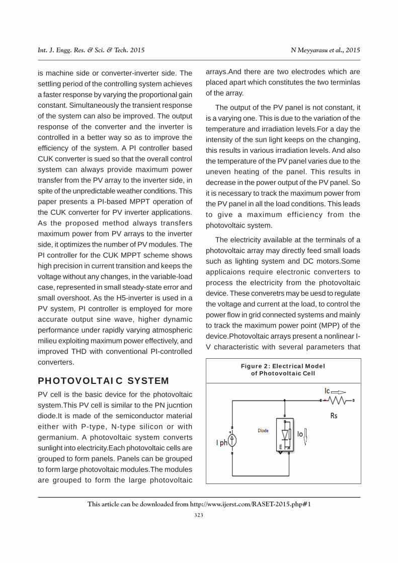
P&O BASED MPPTALGORITHMIn the photovoltaic system, considering theVoltage versus power characteristics, at aparticular point the voltage will be maximum (VMPP)and the power will be maximum (PMPP). This isthe peak power point in the characteristics of thePV panel. It is necessary to track the peak powerpoint of the VI curve to utilize the maximum poweroutput of the photovoltaic cell. We have lot oftechniques under MPPT. Under these techniquesPerturb and observe algorithm is used. P & Otechnique is very simple to implement.
parameters (i.e. power and voltage); that is whyit is extensively used in many MPPT systems[21]–[24]. In addition, it can be easily applied toany PV panel, regardless of the PV module’scharacteristics for the MPPT process.
The P&O method perturbs the duty cycle andcompares instantaneous power with past power.Based on this comparison, the PV voltagedetermines the direction of the next perturbation.P&O shows that, if the power slope increasesand the voltage slope increases also, thereference voltage will increase; otherwise, it willdecrease. The drawback of most of the fuzzy-based MPPT algorithms is that the tracking pointis located away from the maximum power pointwhen the weather conditions change. However,a drawback of P&O technique is that, at steadystate, the operating point oscillates around themaximum power point giving rise to the waste ofavailable energy, particularly in cases of constantor slowly varying atmospheric conditions. Thiscan be solved by decreasing the step size ofperturbation.
The step size of the P&O method affects twoparameters: accuracy and speed. Accuracyincreases when the step size decreases.However, accuracy leads to slow response whenthe environmental conditions change rapidly.Larger step size means higher speed for theMPPT operation, but this will lead to inaccuracyand larger intrinsic oscillations around themaximum power point in steady state. Step sizesshould, thus, be chosen well to achieve highspeed and accuracy. The step-size rate for thevoltage reference signal used is 0.5V/ms.
This is the following general rule used in the P& O method, in which the slope of the PV curveat the MPP is equal to zero.
Figure 3: Current Versus VoltageCharacteristics of Photovoltaic cell
The MPPT control technique is applied toachieve a new reference voltage for the PIcontroller, which changes the duty cycle of thePWM signal for the CUK converter. The P&Oalgorithm has a simple structure and requires few

325
Int. J. Engg. Res. & Sci. & Tech. 2015 N Meyyarasu et al., 2015
This article can be downloaded from http://www.ijerst.com/RASET-2015.php#1
0dPdV
= (1)
converters. It can also provide a better output-current characteristic due to the inductor on theoutput stage. Thus, the CUK configuration is aproper converter to be employed in designing theMPPT.
CUK converter is type of dc-dc to converterthat has the either a high or low output voltagemagnitude with the input voltage magnitude. It isa boost converter followed by the buck converter.In this converter, the capacitor acts as the majorelement for the energy storage component whereas in other converters, inductors are used. ThisCUK converter is classified into two categories:
· Non-isolated CUK Converter.
· Isolated CUK Converter.
Non-isolated CUK converter is found withoutthe transformer. It is an inverting converter i.e.the output voltage is negative with respect to theinput voltage. Isolated CUK converter is isolatedwith the isolation transformer. The ac transformerand a capacitor is additionally connected to theCUK converter circuit. Since the circuit is isolated,the polarity of the output voltage is free to chosen.In this paper non isolated CUK converter is used.The converter circuit consists of two inductors,two capacitors, one transistor and one diode. thecapacitor is used for the energy transfer in thecircuit components and it is alternately connectedbetween the input and output of the converterthrough the commutation of the switch and thediode elements. The inductors L1, L2 in the circuitwhich convert the voltage sources VI and VCO tocurrent sources and these current sources aremaintaining constant current. Charging thecapacitor with the current source limits theresistive current and the associated energy loss.The CUK converter operates either in continuousor discontinuous current mode. It also operates
Figure 4: Traditional P & O technique
Figure 5: Classical CUK Converter Circuit
SELECTION OF DC – DCCONVERTERFor the MPPT operation, the major part is theselection of the DC-DC converter. Since theoutput of the PV is not constant and a varyingone, it is a challenging job to select a highlyefficient converter for the MPPT system. Amongall the topologies available, CUK, SEPIC, Buck-Boost converters provide the opportunity to havetheir higher or lower the output voltage comparedwith the input voltage. Although the buck-boostconfiguration is cheaper than the CUK converter,some disadvantages such as the discontinuousinput current, high peak currents in powercomponents, and poor transient response, makeit less efficient. On the other hand, The CUKconverter has low switching losses and thehighest efficiency among non-isolated dc-dc
326
Int. J. Engg. Res. & Sci. & Tech. 2015 N Meyyarasu et al., 2015
This article can be downloaded from http://www.ijerst.com/RASET-2015.php#1
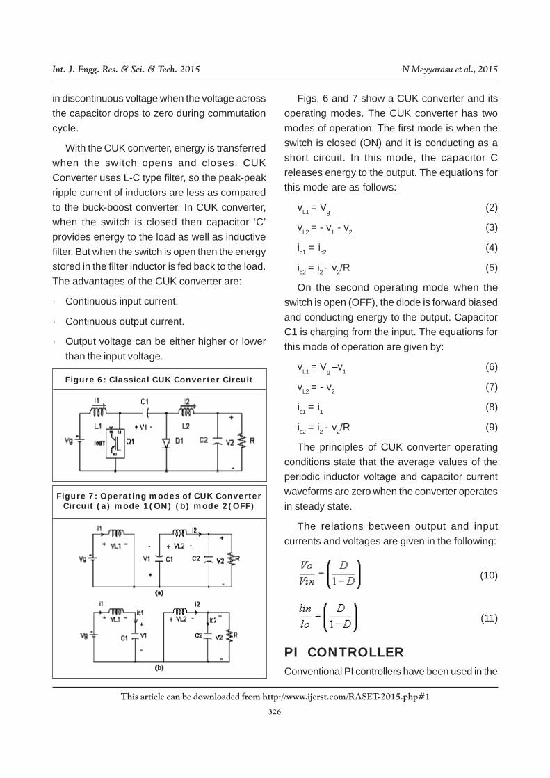
in discontinuous voltage when the voltage acrossthe capacitor drops to zero during commutationcycle.
With the CUK converter, energy is transferredwhen the switch opens and closes. CUKConverter uses L-C type filter, so the peak-peakripple current of inductors are less as comparedto the buck-boost converter. In CUK converter,when the switch is closed then capacitor ‘C’provides energy to the load as well as inductivefilter. But when the switch is open then the energystored in the filter inductor is fed back to the load.The advantages of the CUK converter are:
· Continuous input current.
· Continuous output current.
· Output voltage can be either higher or lowerthan the input voltage.
Figs. 6 and 7 show a CUK converter and itsoperating modes. The CUK converter has twomodes of operation. The first mode is when theswitch is closed (ON) and it is conducting as ashort circuit. In this mode, the capacitor Creleases energy to the output. The equations forthis mode are as follows:
vL1 = Vg (2)
vL2 = - v1 - v2 (3)
ic1 = ic2 (4)
ic2 = i2 - v2/R (5)
On the second operating mode when theswitch is open (OFF), the diode is forward biasedand conducting energy to the output. CapacitorC1 is charging from the input. The equations forthis mode of operation are given by:
vL1 = Vg –v1 (6)
vL2 = - v2 (7)
ic1 = i1 (8)
ic2 = i2 - v2/R (9)
The principles of CUK converter operatingconditions state that the average values of theperiodic inductor voltage and capacitor currentwaveforms are zero when the converter operatesin steady state.
The relations between output and inputcurrents and voltages are given in the following:
(10)
(11)
PI CONTROLLERConventional PI controllers have been used in the
Figure 7: Operating modes of CUK ConverterCircuit (a) mode 1(ON) (b) mode 2(OFF)
Figure 6: Classical CUK Converter Circuit

327
Int. J. Engg. Res. & Sci. & Tech. 2015 N Meyyarasu et al., 2015
This article can be downloaded from http://www.ijerst.com/RASET-2015.php#1
grid tied PV generating systems [12-14]. Acontroller may have different structures. Differentdesign methodologies are there for designing thecontroller on order to achieve the desiredperformance level. But most of the environmentsare initially tested using the PI controller. But thechoice of P-D, P-I, PID depends on the type ofprocess we intend to control. They have theadvantage to be relatively simple to design.
Proportional plus Integral controllers weredeveloped because of the desirable property thatsystems with open loop transfer functions oftype-1 or above have zero steady state error withrespect to step input. This controller does notcause offset associated with the proportionalcontrol. And also it yields much faster responsethan the integral action alone. It is widely used forprocess industries for controlling variables likelevel, flow, pressure, etc., those do not have largetime constants.
Traditionally in order to create a galvanicisolation between the input and the output includea transformer that limits the whole systemperformances in terms of efficiency, weight, sizeand cost. On the contrary, in transformer lessinverters there is no isolation and arecharacterized by little size, lower cost and higherefficiency (more than 2% higher). In grid tied PVinverter system, PV inverter representing the 25%of the whole system cost. There are different PVinverter topologies. They are given by
· Full H-Bridge inverter
· Half H-Bridge inverter
· NPC inverter
· HERIC inverter
· H-5 inverter
Compared to the full H-bridge, this topologypresents an additional transistor, and that is themain difference. The H5 topology is patented bySMA in 2005 and it is based on the same conceptas the HERIC topology, i.e. to disconnect the PVpanels from the grid during current freewheelingperiods, thus having an almost constant commonmode voltage. In Fig.8 it is shown the H-5 topologythat uses a full bridge consisting of the fourswitches T1, T2, T3 and T4, and the DC bypassswitch T5. The switches T1 and T2 are operatedat grid frequency whereas T3, T4 and T5 areoperated at high frequency. During currentfreewheeling period, T5 is open, disconnectingPV panels from the inverter full H-bridge. Thefreewheeling path is closed by the transistor T1and the inverse diode of T3 for the positive halfcycle of the electrical grid, and by the transistorT3 and the inverse diode of T1for the negativehalf cycle.
The classical H-bridge with an extra fifth switch
Figure 8: Comparison among the TransientResponses with P, I, P-I Controllers
TRANSFORMER LESS H5INVERTERInverters used in the photovoltaic systems canbe grouped into two categories:
· Isolated inverters.
· Non-isolated inverters

328
Int. J. Engg. Res. & Sci. & Tech. 2015 N Meyyarasu et al., 2015
This article can be downloaded from http://www.ijerst.com/RASET-2015.php#1
in the positive bus of the DC link which providestwo vital functions:
· It prevents the reactive power exchangebetween L1 and CPV during the zero voltagestate, thus eliminating the high-frequencycontent of VPE. .
· And also it isolates the PV module from thegrid during the zero voltage state, thuseliminating the high frequency content of VPE.
The main features of this inverter are:
· T5 and T4 are switched at high frequency andS1 (S3) at grid frequency.
· Two zero output voltage states are possible:S5 = OFF and S1=ON.
The advantage of this inverter:
· Voltage across the filter is unipolar (0→ +VPV
→ 0 → - VPV → 0), yielding lower core losses.
· Higher efficiency of up to 98% is due to noreactive power exchange between L1 and CPV.
VIRTUAL DC BUS CONCEPTA virtual dc bus concept is introduced to avoidthe increase in common mode voltage currentdue to the transformer less H-bridge inverter. Thegrid neutral line is directly connected to thenegative pole of the PV panel, so that the voltageacross the parasitic capacitance is clamped tozero. This concept prevents any leakage currentflowing across the grid terminals. The Fig. 9shows the concept of the virtual dc busintroduced in the H-bridge inverter. In this, withrespect to the ground point N, the voltage at themidpoint is either zero or +VDC. This is accordingto the switching states in the H-bridge inverter.This virtual dc bus is mainly to generate thenegative output voltage which is necessary forthe inverter operation. The voltage across the real
bus and virtual bus is maintained as same oneby designing the proper switching method.
Figure 9: Virtual DC Bus Concept Circuit
As shown in Fig. 9, when the positive pole ofthe virtual bus is connected to the ground pointN, the voltage at the midpoint C is either zero or –VDC. The dotted line in the figure indicates thatthis connection may be realized directly by a wireor indirectly by a power switch. With the points Band C when joined together by a smart selectingswitch, the voltage at point A can be of threedifferent voltage levels, namely +VDC, zero, and –VDC. By this way the CM current is eliminated withsimple switching structure.
Figure 10: Proposed H-bridge InverterTopology Circuit
329
Int. J. Engg. Res. & Sci. & Tech. 2015 N Meyyarasu et al., 2015
This article can be downloaded from http://www.ijerst.com/RASET-2015.php#1
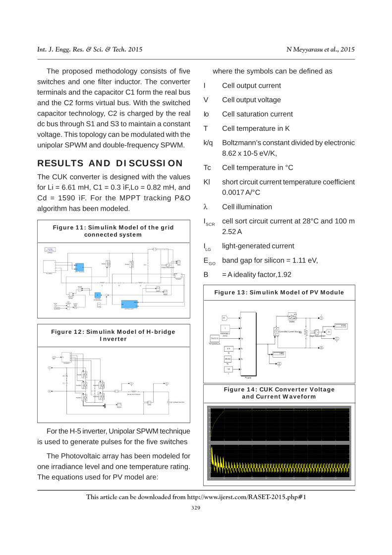
The proposed methodology consists of fiveswitches and one filter inductor. The converterterminals and the capacitor C1 form the real busand the C2 forms virtual bus. With the switchedcapacitor technology, C2 is charged by the realdc bus through S1 and S3 to maintain a constantvoltage. This topology can be modulated with theunipolar SPWM and double-frequency SPWM.
RESULTS AND DISCUSSIONThe CUK converter is designed with the valuesfor Li = 6.61 mH, C1 = 0.3 ìF,Lo = 0.82 mH, andCd = 1590 ìF. For the MPPT tracking P&Oalgorithm has been modeled.
where the symbols can be defined as
I Cell output current
V Cell output voltage
Io Cell saturation current
T Cell temperature in K
k/q Boltzmann’s constant divided by electronic8.62 x 10-5 eV/K,
Tc Cell temperature in °C
Kl short circuit current temperature coefficient0.0017 A/°C
λ Cell illumination
ISCR cell sort circuit current at 28°C and 100 m2.52 A
ILG light-generated current
EGO band gap for silicon = 1.11 eV,
B = A ideality factor,1.92
Figure 11: Simulink Model of the gridconnected system
Figure 12: Simulink Model of H-bridgeInverter
For the H-5 inverter, Unipolar SPWM techniqueis used to generate pulses for the five switches
The Photovoltaic array has been modeled forone irradiance level and one temperature rating.The equations used for PV model are:
Figure 13: Simulink Model of PV Module
Figure 14: CUK Converter Voltageand Current Waveform
330
Int. J. Engg. Res. & Sci. & Tech. 2015 N Meyyarasu et al., 2015
This article can be downloaded from http://www.ijerst.com/RASET-2015.php#1
Tr Reference temperature,308.18 K
Ior Saturation current at tr,=19.963 × 10⁻⁶
Rs Series resistance=0.001
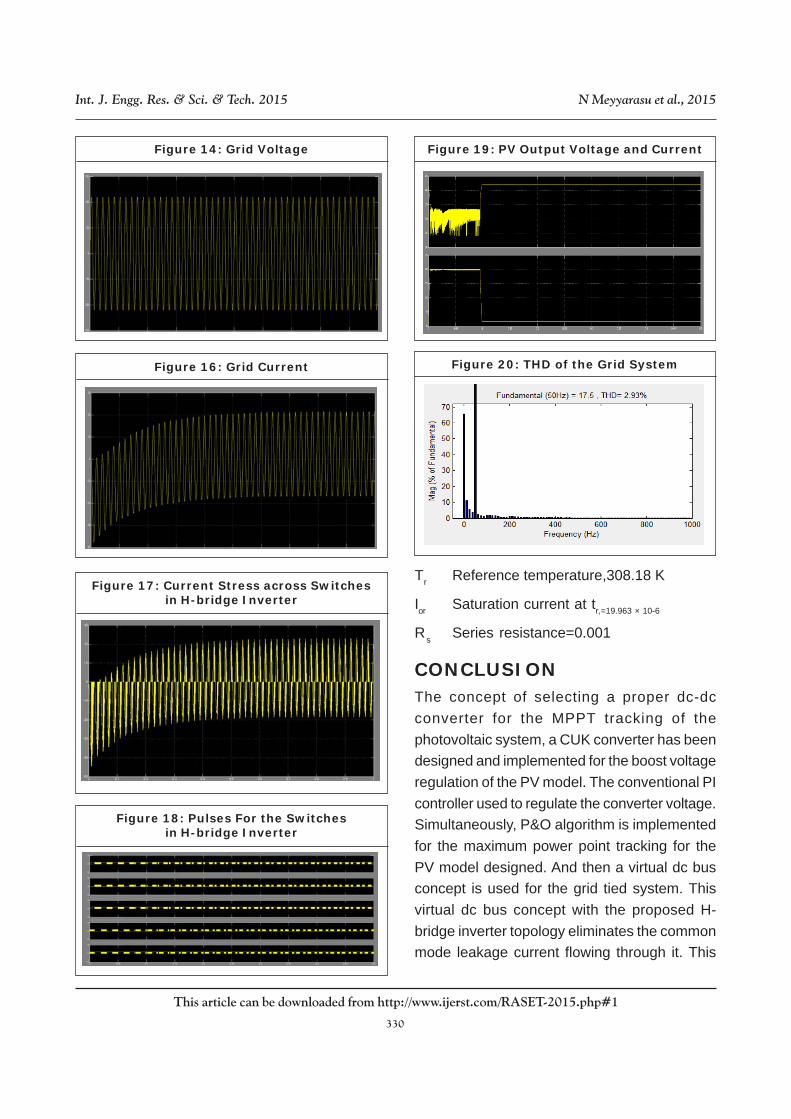
CONCLUSIONThe concept of selecting a proper dc-dcconverter for the MPPT tracking of thephotovoltaic system, a CUK converter has beendesigned and implemented for the boost voltageregulation of the PV model. The conventional PIcontroller used to regulate the converter voltage.Simultaneously, P&O algorithm is implementedfor the maximum power point tracking for thePV model designed. And then a virtual dc busconcept is used for the grid tied system. Thisvirtual dc bus concept with the proposed H-bridge inverter topology eliminates the commonmode leakage current flowing through it. This
Figure 14: Grid Voltage
Figure 16: Grid Current
Figure 17: Current Stress across Switchesin H-bridge Inverter
Figure 18: Pulses For the Switchesin H-bridge Inverter
Figure 19: PV Output Voltage and Current
Figure 20: THD of the Grid System
331
Int. J. Engg. Res. & Sci. & Tech. 2015 N Meyyarasu et al., 2015
This article can be downloaded from http://www.ijerst.com/RASET-2015.php#1
proposed inverter topology in the grid connectedsystem is suitable for single phase small powerapplications where the output current is small sothe extra stresses due to the switched capacitortechnology does not cause serious reality problemfor the power devices and capacitors. A novelinverter topology proposed with the virtual dc busconcept consisting of only five power switchesand one filter inductor eliminates the commonmode current and provides a promising solutionfor the transformer less grid connected system.
REFERENCES1. Tsang K M and W. L. Chan, “Fast acting
regenerative DC electronic load based on aCuk converter,” IEEE Trans. PowerElectron., Vol. 27, No. 1, pp. 269–275, Jan.2012
2. Sanjeev Singh and Bhim Singh, “A Voltage-Controlled PFC Cuk Converter-BasedPMBLDCM Drive for Air-Conditioners, “IEEETransactions on Industry Applications, Vol.48, No. 2, March/April2012
3. M. G. Umamaheswari, G. Uma, and K. M.Vijayalakshmi, “Design and implementationof reduced-order sliding mode controller forhigher-order power factor correctionconverters,” IET Power Electron., Vol. 4, No.9, pp. 984–992, Nov. 2011
4. A. A. Fardoun, E. H. Ismail, A. J. Sabzali,and M. A. Al-Saffar, “New efficient bridgelessCuk rectifiers for PFC applications,” IEEETrans. Power Electron., Vol. 27, No. 7, pp.3292–3301, Jul. 2012.
5. Li Zhang, Kai Sun, Yan Xing and Mu Xing,“H6 Transformer less Full-Bridge PV Grid-Tied Inverters,” IEEE Transactions on PowerElectronics, VOL. 29, NO. 3, MARCH
2014.
6. M.Kannan, G.Neelakrishnan, S.Selvaraju,D.Kalidass, Andril Alagusabai, K.Vijayraj,“High Efficiency Transformer less Inverterfor Single-Phase Photovoltaic Systemsusing Switching Converter,” InternationalJournal of Advanced Research inElectronics and CommunicationEngineering (IJARECE) Volume 2, Issue 11,November 2013
7. C. Zengshi, “PI and sliding mode control ofa Cuk converter,” IEEE Trans. PowerElectron., Vol. 27, No. 8, pp. 3695–3703,Aug. 2012.
8. A. El Khateb, N. A. Rahim, and J. Selvaraj,“Optimized PID controller for both singlephase inverter and MPPT SEPIC DC/DCconverter of PV module,” in Proc. IEEEIEMDC, May 15–18, 2011, pp. 1036–1041.
9. A. El Khateb, N. A. Rahim, J. Selvaraj, andM. N. Uddin, “Maximum power point trackingof single-ended primary-inductor converteremploying a novel optimisation technique forproportional-integralderivative controller,”IET Power Electron., Vol. 6, No. 6, pp. 1111–1121, Jul. 2013.
10. A. El Khateb, N. A. Rahim, and J. Selvaraj,“Fuzzy logic controller for MPPT SEPICconverter and PV single-phase inverter,” inProc. IEEE Symp. ISIEA, Sep. 25–28, 2011,pp. 182–187.
11. N. Mutoh, M. Ohno, and T. Inoue, “A methodfor MPPT control while searching forparameters corresponding to weatherconditions for PV generation systems,” IEEETrans. Ind. Electron., Vol. 53, No. 4, pp.1055– 1065, Jun. 2006.
332
Int. J. Engg. Res. & Sci. & Tech. 2015 N Meyyarasu et al., 2015
This article can be downloaded from http://www.ijerst.com/RASET-2015.php#1
12. F. Pai, R. Chao, S. H. Ko, and T. Lee,“Performance evaluation of parabolicprediction to maximum power point trackingfor PV array,” IEEE Trans. Sustain. Energy,Vol. 2, No. 1, pp. 60–68, Jan. 2011.
13. N. Femia, G. Petrone, G. Spagnuolo, andM.Vitelli, “Optimization of perturb and observemaximum power point tracking method,”IEEE Trans. Power Electron., Vol. 20, No.4, pp. 963–973, Jul. 2005.
14. . A. K. Abdelsalam, A. M. Massoud, S.Ahmed, and P. N. Enjeti, “High-performanceadaptive perturb and observe MPPTtechnique for photovoltaic-basedmicrogrids,” IEEE Trans. Power Electron.,Vol. 26, No. 4, pp. 1010–1021, Apr. 2011.
15. N. A. Rahim, J. Selvaraj, and C.Krismadenata, “Five-level inverter with dualreference modulation technique for grid-connected PV system,” Renew. Energy, Vol.35, No. 3, pp. 712–720, Mar. 2010.
16. D. Sera, R. Teodorescu, J. Hantschel, andM. Knoll, “Optimized maximum power pointtracker for fast-changing environmentalconditions,” IEEE Trans. Ind. Electron., Vol.55, No. 7, pp. 2629–2637, Jul. 2008.
17. N. Femia, D. Granozio, G. Petrone, G.Spagnuolo, and M. Vitelli, “Optimized one-cycle control in photovoltaic grid connectedapplications,” IEEE Trans. Aerosp. Electron.Syst., Vol. 42, No. 3, pp. 954–972, Jul. 2006.
18. M. Fortunato, A. Giustiniani, G. Petrone, G.Spagnuolo, and M. Vitelli, “Maximum powerpoint tracking in a one-cycle-controlledsingle-stage photovoltaic inverter,” IEEETrans. Ind. Electron., Vol. 55, No. 7, pp.2684–2693, Jul. 2008.
19. P. Sanchis, A. Ursua, E. Gubia, and L.Marroyo, “Design and experimentaloperation of a control strategy for the buck-boost DC-AC inverter,” Proc. Inst. Elect.Eng.—Elect. Power Appl., Vol. 152, No. 3,pp. 660–668, May 2005.
20. . L. Bowtell and A. Ahfock, “Direct currentoffset controller for transformerless single-phase photovoltaic grid-connectedinverters,” IET Renew. Power Gen., Vol. 4,No. 5, pp. 428–437, Sep. 2010.
21. A. J. Garrido, I. Garrido, M. Amundarain, M.Alberdi, and M. de la Sen,”Sliding-modecontrol of wave power generation plants,”IEEE Trans.Ind. Appl., Vol. 48, No. 6, pp.2372–2381, Nov./Dec. 2012.
22. F. Cupertino, D. Naso, E. Mininno, and B.Turchiano, “Sliding-mode control withdouble boundary layer for robustcompensation of payload mass and frictionin linear motors,” IEEE Trans. Ind. Appl., Vol.45, No. 5, pp. 1688–1696, Sep./Oct. 2009.
23. Kavya Shree G V, Eranna and K ChandraMohan Reddy, “An Isolated Cuk Converterwith Multiple Outputs Using PWMController,” IEEE Trans. Ind. Appl., Vol. 48,No. 1, pp. 3–11, Jan./Feb. 2012.
24. V. Utkin, J. Guldner, and J. X. Shi, SlidingMode Control in ElectromechanicalSystems. London, U.K.: Taylor & Francis,1999.
25. M. F. Naguib and L. A. C. Lopes, “Harmonicsreduction in current source converters usingfuzzy logic,” IEEE Trans. Power Electron.,Vol. 25, No. 1, pp. 158–167, Jan. 2010.
26. Yunjie Gu, Wuhua Li, Yi Zhao, Bo Yang,Chushan Li and Xiangning He, “Transformer

333
Int. J. Engg. Res. & Sci. & Tech. 2015 N Meyyarasu et al., 2015
This article can be downloaded from http://www.ijerst.com/RASET-2015.php#1
less Inverter With Virtual DC Bus Conceptfor Cost-Effective Grid-Connected PV PowerSystems,” IEEE Transactions on PowerElectronics, Vol. 28, No. 2, February 2013.
27. Azadeh Safari and Saad Mekhilef,“Simulation and Hardware Implementationof Incremental Conductance MPPT WithDirect Control Method Using CukConverter,” IEEE Transactions on IndustrialElectronics, Vol. 58, No. 4, april 2011.
28. M. Singh and A. Chandra, “Application ofadaptive network-based fuzzy inferencesystem for sensorless control of PMSG-based wind turbine with nonlinear-load-
compensation capabilities,” IEEE Trans.Power Electron., Vol. 26, No. 1, pp. 165–175, Jan. 2011.
29. Vashist Bist And Bhim Singh, “PFC CukConverter-Fed BLDC Motor Drive,” IEEETransactions on Power Electronics, Vol. 30,No. 2, February 2015
30. K.Kavitha, Dr. Ebenezer Jeyakumar, “ASynchronous Cuk Converter BasedPhotovoltaic Energy System Design andSimulation,” International Journal ofScientific and Research Publications,Volume 2, Issue 10, October 2012.