GRE G-PRESS Stainless Steel Fittings · 2018-11-09 · GRE G-PRESS Stainless Steel Fittings...
24
GRINNELL G-PRESS Stainless Steel Fittings Worldwide Contacts www.grinnell.com Page 1 of 24 FEBRUARY 2017 G550 General Description GRINNELL G-PRESS Stainless Steel Fittings provide a complete line of mechanically joined press-fittings in sizes 1/2 through 2 inches. These fit- tings are designed to work with Sched- ule 5 or 10 Stainless Steel IPS pipe. Press joints can be readily achieved using several commercially available pressing tools. Several press-fittings are available with male or female threaded ends to enable connectivity with threaded piping systems. Conversion to flanged systems can be made with ANSI Class 125/150, PN 10/16, and BS 10 Table E Flange Adapters. Where breaks in pipe work may be needed, the Union Cou- pling can be used for quick and easy connections/disconnections. Weld and grooved adapters are available to transition to welded or grooved piping systems. G-PRESS Stainless Steel Fittings use a three-step installation process: cutting and de-burring the pipe; marking and inserting pipe into the fitting; and pressing the fitting and pipe together to form a pipe joint using one of the pressing tools identified in Table 4. G-PRESS Stainless Steel Fittings make it easy to quickly and safely install piping systems in a wide range of mechanical, industrial and marine applications. These fittings are made from a highly corrosion-resistant 316 stainless steel and are available with a variety of O-Ring seals, making them suitable for use in numerous applica- tions such as HVAC, plumbing, munici- pal, and industrial installations. G-PRESS Fittings incorporate a unique O-Ring seal design that provides an important Leak-Before-Press feature as shown in Figure 1. When the fitting and pipe are pressed together, they deform to create a durable perma- nent pipe joint, while the O-Ring com- presses to make the joint leak-proof. An improperly pressed fitting allows a leak path for liquids and gases, thereby enabling an installer to identify the incorrectly installed fitting easily. The Leak-Before-Press feature significantly reduces the chance of improper joints, helping to ensure a leak-free system. Main advantages of the G-PRESS Stainless Steel Fittings include the following: • Quick and safe installations • Excellent corrosion resistance • Reduced labor requirements • Easy handling and light weight • Dependability, even under severe use conditions • No fire-watch requirements NOTICE The GRINNELL G-PRESS Stainless Steel Fittings described herein must be installed and maintained in compli- ance with this document, in addition to the standards of any other authori- ties having jurisdiction. Failure to do so may result in serious personal injury or impair the performance of these devices. Never remove any piping component nor correct or modify any piping defi- ciencies without first de-pressurizing and draining the system. Failure to do so may result in serious personal injury, property damage, and/or impaired device performance. It is the designer’s responsibility to select products suitable for the intended service and to ensure that pressure ratings and performance data are not exceeded. Material and gasket selec- tion should be verified for compatibil- ity with the specific application. Always read and understand the installation instructions. The owner is responsible for main- taining their mechanical system and devices in proper operating condi- tion. Contact the installing contrac- tor or product manufacturer with any questions.
Transcript of GRE G-PRESS Stainless Steel Fittings · 2018-11-09 · GRE G-PRESS Stainless Steel Fittings...

GRINNELL G-PRESS Stainless Steel Fittings
Worldwide Contacts www.grinnell.com
Page 1 of 24 FEBRUARY 2017 G550
General DescriptionGRINNELL G-PRESS Stainless Steel Fittings provide a complete line of mechanically joined press-fittings in sizes 1/2 through 2 inches. These fit-tings are designed to work with Sched-ule 5 or 10 Stainless Steel IPS pipe. Press joints can be readily achieved using several commercially available pressing tools.Several press-fittings are available with male or female threaded ends to enable connectivity with threaded piping systems. Conversion to flanged systems can be made with ANSI Class 125/150, PN 10/16, and BS 10 Table E Flange Adapters. Where breaks in pipe work may be needed, the Union Cou-pling can be used for quick and easy connections/disconnections. Weld and grooved adapters are available to transition to welded or grooved piping systems.G-PRESS Stainless Steel Fittings use a three-step installation process: cutting and de-burring the pipe; marking and inserting pipe into the fitting; and pressing the fitting and pipe together to form a pipe joint using one of the pressing tools identified in Table 4.G-PRESS Stainless Steel Fittings make it easy to quickly and safely install piping systems in a wide range of mechanical, industrial and marine applications. These fittings are made from a highly corrosion-resistant 316 stainless steel and are available with a variety of O-Ring seals, making them suitable for use in numerous applica-tions such as HVAC, plumbing, munici-pal, and industrial installations.G-PRESS Fittings incorporate a unique O-Ring seal design that provides an important Leak-Before-Press feature as shown in Figure 1. When the fitting and pipe are pressed together, they deform to create a durable perma-nent pipe joint, while the O-Ring com-presses to make the joint leak-proof. An improperly pressed fitting allows a leak path for liquids and gases, thereby enabling an installer to identify the incorrectly installed fitting easily. The
Leak-Before-Press feature significantly reduces the chance of improper joints, helping to ensure a leak-free system.
Main advantages of the G-PRESS Stainless Steel Fittings include the following:
• Quick and safe installations
• Excellent corrosion resistance
• Reduced labor requirements
• Easy handling and light weight
• Dependability, even under severe use conditions
• No fire-watch requirements
NOTICEThe GRINNELL G-PRESS Stainless Steel Fittings described herein must be installed and maintained in compli-ance with this document, in addition to the standards of any other authori-ties having jurisdiction. Failure to do so may result in serious personal injury or impair the performance of these devices.Never remove any piping component nor correct or modify any piping defi-ciencies without first de-pressurizing and draining the system. Failure to do so may result in serious personal injury, property damage, and/or impaired device performance.It is the designer’s responsibility to select products suitable for the intended service and to ensure that pressure ratings and performance data are not exceeded. Material and gasket selec-tion should be verified for compatibil-ity with the specific application. Always read and understand the installation instructions.The owner is responsible for main-taining their mechanical system and devices in proper operating condi-tion. Contact the installing contrac-tor or product manufacturer with any questions.

G550Page 2 of 24
• Fluoroelastomer O-Ring Seal Green color, Grade “O” -22º F to 300º F (-30°C to 149°C)For oxidizing acids, petro-leum products, hydraulic flu-ids, lubricants, and halogenated hydrocarbons.
Required PipeG-PRESS Stainless Steel Fittings are designed for use with Schedule 5 or 10 Type 304/304L or 316/316L Stain-less Steel pipe conforming to ASTM A-312. Refer to Table 2 for pipe toler-ance specifications.
Hanger SupportsG-PRESS Stainless Steel Fittings can be suspended on hangers, brackets, or other supports with the maximum verti-cal and horizontal spacing as indicated in Table 2. Details by pipe manufacturers or application requirements may specify additional hanging requirements.
Proper bearing and spacing of sup-ports is necessary to prevent excessive bending or sagging when supporting pipe.
Pipe ClearancesFor locations where there is insufficient access to accommodate the pressing tool, consider pre-fabricating the pipe-work or using an alternate joining solu-tion. Tables 5 and 6 show the minimum clearances required for wall and corner installations.
Minimum Fitting DistanceTable 3 provides recommended minimum distances between fittings to permit mechanical forming of the pipe during the pressing process.
Pressing ToolsThe G-PRESS system uses only Type M press configuration and can be installed using any of the press tools shown in Table 4.
The tools are powered with a recharge-able battery. Each tool has a unique set of easily interchangeable jaws/collars for each pipe size.
WARNINGThe tool manufacturer’s operating instructions must be strictly followed. Improper use of pressing tools may cause damage to the press device, its accessories, or pipes, potentially resulting in leaks and/or injury. Read and understand all manufacturer’s instructions before operating press-fitting equipment.
Keep body parts and foreign objects away from the press jaws during the pressing operation.
Technical DataApprovalsCertified to all requirements of NSF/ANSI 61, Annex G and NSF/ANSI 372.
GRINNELL G-PRESS Stainless Steel Fittings have IAPMO certifications and are compliant with ASME B31.1, B31.3, and B31.9 piping codes. See Table 1 for a detailed summary of approvals.
Working PressureThe working pressure range is from full vacuum to 300 psi (20,7 bar) on Sched-ule 5 or 10 Stainless Steel Pipe for 1/2 inch through 2 inches.
Working TemperatureDepending on O-Ring Seal selection, temperatures range from -22º F to 300º F (-30°C to 149°C).
Refer to the O-Ring Seals section in this data sheet for specific tempera-ture ranges.
Threaded ConnectionsAll threaded connections meet ANSI/ASME B 1.20.1 NPT or ISO 7R (for external threads) and ISO 7-1Rp (for internal threads).
Flange ConnectionsFlange connections are compatible with ANSI Class 125/150, PN 16 and BS 10 Table E bolt patterns.
MaterialsFitting HousingStainless Steel per AISI 316/316L with a wall thickness of 0.065 inches (1,65 mm) and the following characteristics:
• Hygienic material often used in the food, beverage, and pharma-ceutical industries
• Higher surface roughness friction factor resulting in less flow loss
• Excellent corrosion resistance
O-Ring SealsFor O-Ring Seal compound applica-tions, refer to Technical Data Sheet G610.
• EPDM O-Ring Seal Black color, Grade “E” –4º F to 230º F (-20°C to 110°C)For hot water, dilute acids, alka-lis, oil-free air, and many chemi-cal services. Excellent oxidation resistance. NOT FOR USE WITH HYDROCARBONS.
• Nitrile O-Ring Seal Gray color, Grade “T” -13º F to 230º F (-25°C to 110°C)Petroleum products, vegetable oils, mineral oils, and air with oils. NOT FOR USE WITH HOT WATER OR HOT DRY AIR.
Incorrect or improper use or the use of worn or damaged press tools and press devices carries a risk of injury from ejected fragments. Therefore, adhere to these instructions:
• Service and maintenance of tools must comply with manufacturers’ specifications.
• Ensure only trained personnel oper-ate press tools and press devices.
• Check pressing tools and press de-vices for cracks and other signs of wear before each use.
• Only use pressing tools and press devices that are in proper working condition.
• Discard any pressing tools and press devices showing signs of wear or cracks.
PREPAREDPIPE-END
G-PRESSFITTING
HOUSING
PIPESTOP
PRESS DEFORMATIONON FITTING HOUSINGAREA BEYOND O-RING
BEAD AS SHOWN
COMPRESSEDO-RING SEAL
O-RINGBEAD
COMPLETEDFITTING
AND PIPEJOINT
O-RING SEALWITH LEAK-BEFORE
PRESS FEATURE
FIGURE 1 FITTING CROSS SECTION

G550Page 3 of 24
Fitting Type Figure No. Thread Type/Bolt Pattern O-Ring Material IAPMO NSF
Non - threaded Fittings407, 408, 442, 461, 467, 468, 470, 471, 484, 485,473, 474
N/A
EPDM Y Y
Nitrile Y Y
Fluoroelastomer N N
Threaded Fittings 476, 478, 479
ISO 7R/7-1 RP
EPDM Y Y
Nitrile Y Y
Fluoroelastomer N N
ANSI/ASME B.1.20.1
EPDM Y Y
Nitrile Y Y
Fluoroelastomer N N
Flange Adapters 466, 475
ANSI 125/250
EPDM Y Y
Nitrile Y Y
Fluoroelastomer N N
DIN PN16, Table E
EPDM N N
Nitrile N N
Fluoroelastomer N N
Other Fittings 477 N/A
EPDM Y Y
Nitrile Y Y
Fluoroelastomer N N
Nominal Pipe Size Pipe Tolerance Pipework Support
InchesPipe OD Inches
mm
Pipe OD Tolerance
+/- Inches
mm
Pipe Wall Thickness Schedule 5
Inchesmm
Pipe Wall Thickness
Schedule 10 Inches
mm
Vertical Intervals
Feetm
Horizontal Intervals
Feetm
1/2 0.84021,3
0.0040,10
0.0651,65
0.0832,11
61,8
41,2
3/4 1.05026,7
0.0060,14
0.0651,65
0.0832,11
61,8
51,5
1 1.31533,4
0.0060,14
0.0651,65
0.1092,77
82,4
61,8
1-1/4 1.66042,2
0.0070,18
0.0651,65
0.1092,77
92,7
72,1
1-1/2 1.90048,3
0.0080,20
0.0651,65
0.1092,77
103,1
82,4
2 2.37560,3
0.0110,28
0.0651,65
0.1092,77
103,1
82,4
TABLE 2 PIPE TOLERANCE AND SUPPORT
TABLE 1 G-PRESS STAINLESS STEEL FITTINGS
AGENCY APPROVALS

G550Page 4 of 24
Tool Manufacturer
Pipe Schedule
Fitting Size
Model Number
Novopress 5 or 10 1/2 to 1-1/2 Inches ACO202
Novopress 5 or 10 1/2 to 2 Inches AFP202XL
Milwaukee 5 or 10 1/2 to 1 Inches M18
Milwaukee 5 or 10 1/2 to 2 Inches M18 XL
Nominal Pipe Size
AMinimum Distance Between Fittings Inches
mm
LMinimum
Pipe Length Between Fittings Inches
mm
ESocket
Insertion Depth Inches
mm
DFitting
Housing Diameter
Inchesmm
InchesPipe OD Inches
mm
1/2 0.84021,3
0.3910
2.0552
0.8321
1.2632
3/4 1.05026,7
0.3910
2.2858
0.9424
1.4637
1 1.31533,4
0.3910
2.4462
1.0226
1.7344
1-1/2 1.90048,3
0.3910
3.2382
1.2231
2.4863
2 2.37560,3
0.7920
4.33110
1.2231
3.0878
Dimensions may vary slightly based on pressing tool
L
A E
D
TABLE 3 MINIMUM FITTING DISTANCES
TABLE 4 APPROVED PRESSING TOOLS
G550Page 5 of 24
Nominal Pipe Size A
Minimum Wall to Fitting
Distance Inches
mm
BMinimum Horizontal
Pipe Distance from Wall
Inchesmm
CMinimum Vertical
Pipe Distance from Wall
Inchesmm
InchesPipe OD Inches
mm
1/2 0.84021,3
1.3835
2.2056
3.7896
3/4 1.05026,7
1.3835
2.3259
4.21107
1 1.31533,4
1.3835
2.4061
4.76121
1-1/2 1.90048,3
1.3835
2.6066
5.08129
2 2.37560, 3
1.3835
3.1580
6.38162
Dimensions may vary slightly based on pressing tool
A
B
C
TABLE 5 MINIMUM WALL CLEARANCES FOR
PERPENDICULAR PIPE RUNS

G550Page 6 of 24
Wall and Pipe ClearancesNominal Pipe Size A
Wall Clearance Inches
mm
B Parallel Pipe
Clearance Inches
mmInches
Pipe OD Inches
mm
1/2 0.84021,3
0.87522
2.2557
3/4 1.05026,7
0.87522
2.37560
1 1.31533,4
1.0025
2.62567
1-1/2 1.90048,3
1.18830
3.0076
2 2.37560,3
2.37560
5.625143
2* 2.37560,3
3.0076
4.625117
* Loop-Type Jaw clearancesDimensions may vary slightly based on pressing tool
Corner and Pipe ClearancesNominal Pipe Size A
Wall Clearance Inches
mm
B Wall Clearance
Inchesmm
C Parallel Pipe
Clearance Inches
mmInches
Pipe OD Inches
mm
1/2 0.84021,3
0.87522
1.2532
3.0076
3/4 1.05026,7
1.0025
1.12529
3.0076
1 1.31533,4
1.2532
1.37535
2.62580
1-1/2 1.90048,3
1.2532
1.7544
3.0076
2 2.37560,3
2.37560
4.375111
5.625143
2* 2.37560,3
3.0076
3.0076
4.625117
* Loop-Type Jaw clearancesDimensions may vary slightly based on pressing tool
A
B
B
C
A
TABLE 6 MINIMUM WALL CLEARANCES FOR
PARALLEL PIPE RUNS (1 OF 2)
G550Page 7 of 24
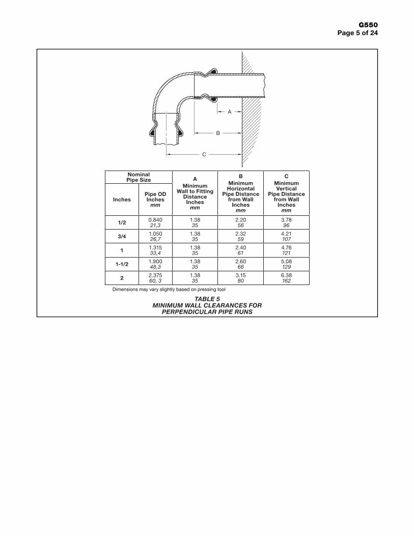
Design CriteriaInstallation of the GRINNELL G-PRESS Stainless Steel Fittings involves a three-step process: cutting and de-burring the pipe; marking and inserting the pipe into the fitting; and pressing the fitting and pipe to form the pipe joint using an approved pressing tool.The pipe is inserted into the fitting until it reaches the pipe stop, with the exception of the Figure 408 Slip Cou-pling. The O-Ring Seal at this time is resting on the pipe at the end of the fitting. When the joint is pressed, the fitting is deformed and the O-Ring Seal is compressed, forming a seal. The strength of the joint results from press-ing the fitting and the pipe together to create a durable, inseparable joint.The Figure 408 Slip Coupling is a special coupling that does not have a pipe stop and can be slid completely on one pipe. This feature allows the installer to align the pipes and slide the coupling back over the adjoining pipe in a tight space where the normal cou-pling take-out is not available.
Accommodations for Thermal ExpansionStainless steel pipe has a thermal expansion 9.6 x 10⁻⁶ in/in °F (17.3 x 10⁻⁶ mm/mm °C). The change in pipe length due to the change in temperature can be calculated using the formula:
∆L = L α ∆T
where:
∆L is the change in pipe length.
α is the thermal expansion rate.
∆T is the change in temperature.
Table 7 shows commonly calculated values in inches of pipe expansion for a given temperature rise, whereas Table 8 shows this information in millimeters.
For piping in domestic hot water and heating installations, the limited size of rooms, and hence straight pipe runs, combined with the many bends and offsets that normally occur, will result in thermal movement being accommo-dated automatically. However where long straight pipe runs, exceeding 20 ft (6 m), are encountered, allowance for expansion should be considered.
Recess and Pipe ClearanceNominal Pipe Size A
Wall Clearance Inches
mm
B Parallel Pipe
Clearance Inches
mm
C Minimum
Recess Width Inches
mmInches
Pipe OD Inches
mm
1/2 0.84021,3
0.87522
3.0076
0.62516
3/4 1.05026,7
1.0025
3.0076
5.25133
1 1.31533,4
1.2532
2.62580
6.00152
1-1/2 1.90048,3
1.2532
2.62580
6.75171
2 2.37560,3
2.37560
5.625143
14.25362
2* 2.37560,3
3.0076
4.625117
10.50267
* Loop-Type Jaw clearancesDimensions may vary slightly based on pressing tool
CB
A4"
(100 mm)
TABLE 6 MINIMUM WALL CLEARANCES FOR
PARALLEL PIPE RUNS (2 OF 2)

G550Page 8 of 24
Change in Length of 304 Stainless Steel Pipe Due to Temperature Change (Inches)
Pipe Length
Ft
Change in Temperature °F
-100 -70 -50 -25 0 25 50 75 100 125 150 175 200
20 -0.23 -0.16 -0.12 -0.06 0.00 0.06 0.12 0.17 0.23 0.29 0.35 0.40 0.46
40 -0.46 -0.32 -0.23 -0.12 0.00 0.12 0.23 0.35 0.46 0.58 0.69 0.81 0.92
60 -0.69 -0.48 -0.35 -0.17 0.00 0.17 0.35 0.52 0.69 0.86 1.04 1.21 1.38
80 -0.92 -0.65 -0.46 -0.23 0.00 0.23 0.46 0.69 0.92 1.15 1.38 1.61 1.84
100 -1.15 -0.81 -0.58 -0.29 0.00 0.29 0.58 0.86 1.15 1.44 1.73 2.02 2.30
120 -1.38 -0.97 -0.69 -0.35 0.00 0.35 0.69 1.04 1.38 1.73 2.07 2.42 2.76
140 -1.61 -1.13 -0.81 -0.40 0.00 0.40 0.81 1.21 1.61 2.02 2.42 2.82 3.23
160 -1.84 -1.29 -0.92 -0.46 0.00 0.46 0.92 1.38 1.84 2.30 2.76 3.23 3.69
180 -2.07 -1.45 -1.04 -0.52 0.00 0.52 1.04 1.56 2.07 2.59 3.11 3.63 4.15
200 -2.30 -1.61 -1.15 -0.58 0.00 0.58 1.15 1.73 2.30 2.88 3.46 4.03 4.61
For 316SS pipe multiply values by 0.92
Change in Length of 304 Stainless Steel Pipe Due to Temperature Change (mm)
Pipe Length
M
Change in Temperature °C
-100 -70 -50 -25 0 25 50 75 100 125 150 175 200
10 -17 -12 -9 -4 0 4 9 13 17 22 26 30 35
20 -35 -24 -17 -9 0 9 17 26 35 43 52 60 69
30 -52 -36 -26 -13 0 13 26 39 52 65 78 91 104
40 -69 -48 -35 -17 0 17 35 52 69 86 104 121 138
50 -86 -60 -43 -22 0 22 43 65 86 108 130 151 173
60 -104 -73 -52 -26 0 26 52 78 104 130 156 181 207
70 -121 -85 -60 -30 0 30 60 91 121 151 181 212 242
80 -138 -97 -69 -35 0 35 69 104 138 173 207 242 276
90 -156 -109 -78 -39 0 39 78 117 156 194 233 272 311
100 -173 -121 -86 -43 0 43 86 130 173 216 259 302 346
For 316SS pipe multiply values by 0.92
TABLE 7 THERMAL EXPANSION RATES FOR STAINLESS STEEL PIPE
IMPERIAL UNITS
TABLE 8 THERMAL EXPANSION RATES FOR STAINLESS STEEL PIPE
METRIC UNITS
G550Page 9 of 24
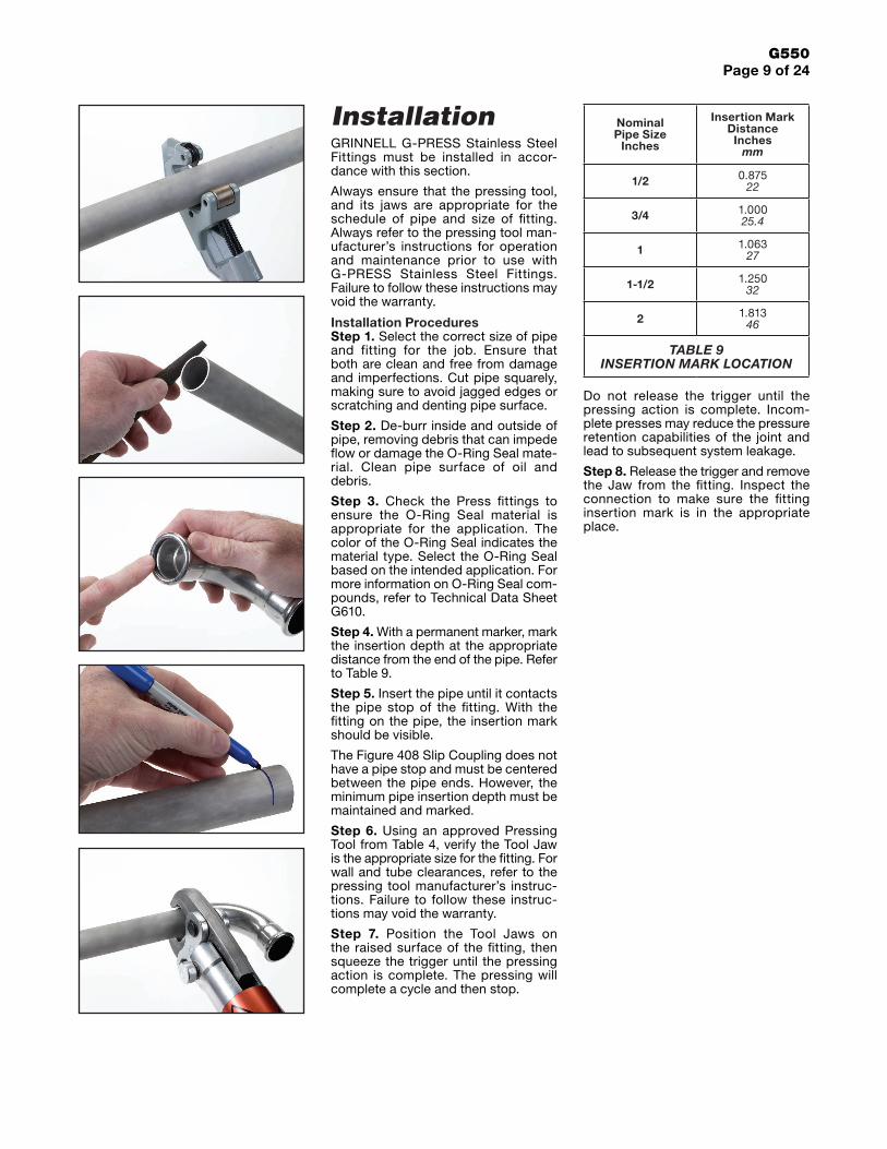
Do not release the trigger until the pressing action is complete. Incom-plete presses may reduce the pressure retention capabilities of the joint and lead to subsequent system leakage.
Step 8. Release the trigger and remove the Jaw from the fitting. Inspect the connection to make sure the fitting insertion mark is in the appropriate place.
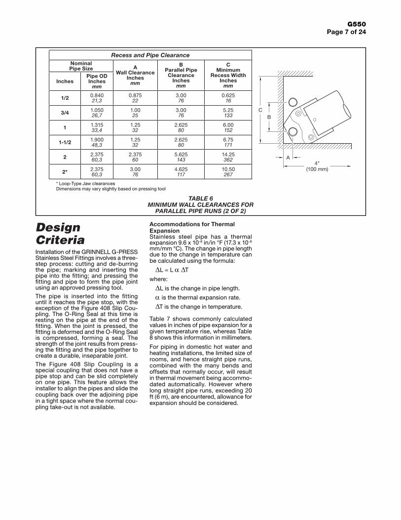
InstallationGRINNELL G-PRESS Stainless Steel Fittings must be installed in accor-dance with this section.
Always ensure that the pressing tool, and its jaws are appropriate for the schedule of pipe and size of fitting. Always refer to the pressing tool man-ufacturer’s instructions for operation and maintenance prior to use with G-PRESS Stainless Steel Fittings. Failure to follow these instructions may void the warranty.
Installation ProceduresStep 1. Select the correct size of pipe and fitting for the job. Ensure that both are clean and free from damage and imperfections. Cut pipe squarely, making sure to avoid jagged edges or scratching and denting pipe surface.
Step 2. De-burr inside and outside of pipe, removing debris that can impede flow or damage the O-Ring Seal mate-rial. Clean pipe surface of oil and debris.
Step 3. Check the Press fittings to ensure the O-Ring Seal material is appropriate for the application. The color of the O-Ring Seal indicates the material type. Select the O-Ring Seal based on the intended application. For more information on O-Ring Seal com-pounds, refer to Technical Data Sheet G610.
Step 4. With a permanent marker, mark the insertion depth at the appropriate distance from the end of the pipe. Refer to Table 9.
Step 5. Insert the pipe until it contacts the pipe stop of the fitting. With the fitting on the pipe, the insertion mark should be visible.
The Figure 408 Slip Coupling does not have a pipe stop and must be centered between the pipe ends. However, the minimum pipe insertion depth must be maintained and marked.
Step 6. Using an approved Pressing Tool from Table 4, verify the Tool Jaw is the appropriate size for the fitting. For wall and tube clearances, refer to the pressing tool manufacturer’s instruc-tions. Failure to follow these instruc-tions may void the warranty.
Step 7. Position the Tool Jaws on the raised surface of the fitting, then squeeze the trigger until the pressing action is complete. The pressing will complete a cycle and then stop.
Nominal Pipe Size
Inches
Insertion Mark Distance Inches
mm
1/2 0.87522
3/4 1.00025.4
1 1.06327
1-1/2 1.25032
2 1.81346
TABLE 9 INSERTION MARK LOCATION

G550Page 10 of 24
Nominal Pipe Size Nominal Dimensions Approx.
Weight Lbs.kg
Part Number*
InchesPipe OD Inches
mm
A Inches
mm
B Inches
mm
1/2 0.84021,3
0.4210,7
2.0953,1
0.130,1 407050
3/4 1.05026,7
0.4411,2
2.3359,2
0.180,1 407075
1 1.31533,4
0.4310,9
2.4863,0
0.230,1 407100
1-1/2 1.90048,3
0.4310,9
2.8472,1
0.400,2 407150
2 2.37560,3
0.5012,7
4.05103
0.740,3 407200
* To Part Number, add the following suffix to identify O-Ring Seal: “E” for EPDM, “T” for Nitrile, and “O” for Fluoroelastomer.
Nominal Pipe Size Nominal Dimensions
Approx. Weight
Lbs.kg
Part Number*
InchesPipe OD Inches
mm
A Minimum Pipe
Insertion Depth Inches
mm
B Inches
mm
1/2 0.84021,3
0.8321,1
2.9574,9
0.180,1 408050
3/4 1.05026,7
0.9524,1
3.4086,4
0.250,1 408075
1 1.31533,4
1.0225,9
3.8397,3
0.340,2 408100
1-1/2 1.90048,3
1.2030,5
4.81122
0.630,3 408150
2 .37560,3
1.7745,0
6.76172
1.130,5 408200
* To Part Number, add the following suffix to identify O-Ring Seal: “E” for EPDM, “T” for Nitrile, and “O” for Fluoroelastomer.
A
B
AA
B
TABLE 10 G-PRESS FIGURE 407 COUPLING
NOMINAL DIMENSIONS
TABLE 11 G-PRESS FIGURE 408 SLIP COUPLING
NOMINAL DIMENSIONS

G550Page 11 of 24
Nominal Pipe Size Nominal Dimensions Approx.
Weight Lbs.kg
Part Number*
InchesPipe OD Inches
mm
A Inches
mm
B Inches
mm
1/2 0.84021,3
1.5739,9
2.4161,2
0.220,1 468050
3/4 1.05026,7
1.8948,0
2.8472,1
0.330,1 468075
1 1.31533,4
2.3760,2
3.4086,4
0.480,2 468100
1-1/2 1.90048,3
2.5665,0
3.7695,5
0.790,4 468150
2 2.37560,3
3.2382,0
5.00127
1.390,6 468200
* To Part Number, add the following suffix to identify O-Ring Seal: “E” for EPDM, “T” for Nitrile, and “O” for Fluoroelastomer.
Nominal Pipe Size Nominal Dimensions Approx.
Weight Lbs.kg
Part Number*
InchesPipe OD Inches
mm
A Inches
mm
B Inches
mm
1/2 0.84021,3
0.7920,1
1.6241,1
0.200,1 470050
3/4 1.05026,7
0.9022,9
1.8547,0
0.260,1 470075
1 1.31533,4
1.1328,7
2.1454,4
0.370,2 470100
1-1/2 1.90048,3
1.1729,7
2.3760,2
0.600,3 470150
2 2.37560,3
1.4837,6
3.2482,3
1.060,5 470200
* To Part Number, add the following suffix to identify O-Ring Seal: “E” for EPDM, “T” for Nitrile, and “O” for Fluoroelastomer.
AB
B
A
A
B
TABLE 12 G-PRESS FIGURE 468 90° ELBOW
NOMINAL DIMENSIONS
TABLE 13 G-PRESS FIGURE 470 45° ELBOW FEMALE X MALE
NOMINAL DIMENSIONS

G550Page 12 of 24
Nominal Pipe Size Nominal Dimensions Approx.
Weight Lbs.kg
Part Number*
InchesPipe O.D.
Inchesmm
A Inches
mm
B Inches
mm
C Inches
mm
1/2 0.84021,3
1.5739,9
2.8772,9
2.4161,2
0.240,1 467050
3/4 1.05026,7
1.8948,0
3.2783,0
2.8472,1
0.330,1 467075
1 1.31533,4
2.3760,2
3.8297,0
3.4086,4
0.370,2 467100
1-1/2 1.90048,3
2.4863,0
4.06103
3.6993,7
0.770,3 467150
2 2.37560,3
3.2382,0
5.52140
5.00127
1.340,6 467200
* To Part Number, add the following suffix to identify O-Ring Seal: “E” for EPDM, “T” for Nitrile, and “O” for Fluoroelastomer.
Nominal Pipe Size Nominal Dimensions Approx.
Weight Lbs.kg
Part Number*
InchesPipe OD Inches
mm
A Inches
mm
B Inches
mm
1/2 0.84021,3
0.7920,1
1.6241,1
0.180,1 471050
3/4 1.05026,7
0.9022,9
1.8547,0
0.240,1 471075
1 1.31533,4
1.1328,7
2.1454,4
0.370,2 471100
1-1/2 1.90048,3
1.1729,7
2.3760,2
0.590,3 471150
2 2.37560,3
1.4837,6
3.2482,3
1.060,5 471200
* To Part Number, add the following suffix to identify O-Ring Seal: “E” for EPDM, “T” for Nitrile, and “O” for Fluoroelastomer.
B
ABA
B
A
C
A
TABLE 14 G-PRESS FIGURE 467 90° ELBOW FEMALE X MALE
NOMINAL DIMENSIONS
TABLE 15 G-PRESS FIGURE 471 45° ELBOW
NOMINAL DIMENSIONS

G550Page 13 of 24
Nominal Pipe Size Nominal Dimensions
Approx. Weight
Lbs.kg
Part Number*
InchesPipe OD Inches
mm
A Inches
mm
B Inches
mm
C Inches
mm
D Inches
mm
1/2 0.84021,3
1.2832,5
0.8020,3
1.4837,6
1.6441,7
0.240,1 442050
3/4 1.05026,7
1.5038,1
0.9223,4
1.7043,2
1.8747,5
0.330,1 442075
1 1.31533,4
1.7845,2
1.0727,2
1.9148,5
2.0953,1
0.460,2 442100
1-1/2 1.90048,3
3.1981,0
1.4236,1
2.8071,1
2.6366,8
0.920,4 442150
2 2.37560,3
3.2281,8
1.6140,9
3.3986,1
3.3986,1
1.480,7 442200
* To Part Number, add the following suffix to identify O-Ring Seal: “E” for EPDM, “T” for Nitrile, and “O” for Fluoroelastomer.
BA
D
CC
TABLE 16 G-PRESS FIGURE 442 TEE
NOMINAL DIMENSIONS

G550Page 14 of 24
Nominal Pipe Size Nominal Dimensions Approx.
Weight Lbs.kg
Part Number*Inches
Run x Run x Branch
Pipe OD Inches
mm
A Inches
mm
B Inches
mm
C Inches
mm
D Inches
mm
3/4 x 3/4 x 1/2 1.050 x 1.050 x 0.84026,7 x 26,7 x 21,3
1.5038,1
0.9123,1
1.7043,2
1.7444,2
0.310,1 4737505
1 x 1 x 1/2 1.315 x 1.315 x 0.84033,4 x 33,4 x 21,3
1.7845,2
1.0626,9
1.9148,5
1.8948,0
0.400,2 4731005
1 x 1 x 3/4 1.315 x 1.315 x 1.05033,4 x 33,4 x 26,7
1.7845,2
1.0727,2
1.9148,5
2.0251,3
0.420,2 4731075
1-1/2 x 1-1/2 x 1/2 1.900 x 1.900 x 0.84048,3 x 48,3 x 21,3
3.1981,0
1.3534,3
2.8071,1
2.1955,6
0.790,4 4731505
1-1/2 x 1-1/2 x 3/4 1.900 x 1.900 x 1.05048,3 x 48,3 x 26,7
3.1981,0
1.3734,8
2.8071,1
2.3158,7
0.810,4 4731575
1-1/2 x 1-1/2 x 1 1.900 x 1.900 x 1.31548,3 x 48,3 x 33,4
3.1981,0
1.4236,1
2.8071,1
2.4562,2
0.840,4 4731510
2 x 2 x 1/2 2.375 x 2.375 x 0.84060,3 x 60,3 x 21,3
3.2281,8
1.6040,6
3.3986,1
2.4462,0
1.170,5 4732005
2 x 2 x 3/4 2.375 x 2.375 x 1.05060,3 x 60,3 x 26,7
3.2281,8
1.6241,1
3.3986,1
2.5665,0
1.190,5 4732075
2 x 2 x 1 2.375 x 2.375 x 1.31560,3 x 60,3 x 33,4
3.2281,8
1.6140,9
3.3986,1
2.6266,5
1.230,6 4732010
2 x 2 x 1-1/2 2.375 x 2.375 x 1.90060,3 x 60,3 x 48,3
3.2281,8
1.6140,9
3.3986,1
2.8271,6
1.320,6 4732015
* To Part Number, add the following suffix to identify O-Ring Seal: “E” for EPDM, “T” for Nitrile, and “O” for Fluoroelastomer.
BA
C C
D
TABLE 17 G-PRESS FIGURE 473 REDUCING TEE
NOMINAL DIMENSIONS
G550Page 15 of 24
Nominal Pipe Size Nominal Dimensions Approx.
Weight Lbs.kg
Part Number*
InchesRun x Run x Branch
Pipe OD Inches
mm
A Inches
mm
B Inches
mm
C Inches
mm
D Inches
mmNPT ISO/BSP
1/2 x 1/2 x 1/2 0.840 x 0.840 x 0.84021,3 x 21,3 x 21,3
1.2832,5
0.9323,6
1.4837,6
1.5238,6
0.260,1 4780505 478T0505
1/2 x 1/2 x 3/4 0.840 x 0.840 x 1.05021,3 x 21,3 x 26,7
1.2832,5
1.3033,0
1.4837,6
1.8446,7
0.370,2 4780575 478T0575
3/4 x 3/4 x 1/2 1.050 x 1.050 x 0.84026,7 x 26,7 x 21,3
1.5038,1
1.0426,4
1.7043,2
1.6341,4
0.330,1 4787505 478T7505
3/4 x 3/4 x 3/4 1.050 x 1.050 x 1.05026,7 x 26,7 x 26,7
1.5038,1
1.2732,3
1.7043,2
1.8146,0
0.400,2 4787575 478T7575
3/4 x 3/4 x 1 1.050 x 1.050 x 1.31526,7 x 26,7 x 33,4
1.5038,1
1.2932,8
1.7043,2
1.9750,0
0.460,2 4787510 478T7510
1 x 1 x 1 1.315 x 1.315 x 1.31533,4 x 33,4 x 33,4
1.7845,2
1.2331,2
1.9148,5
2.0151.1
0.650,3 4781010 478T1010
1 x 1 x 1/2 1.315 x 1.315 x 0.84033,4 x 33,4 x 21,3
1.7845,2
1.1930,2
1.9148,5
1.7845,2
0.420,2 4781015 478T1015
1 x 1 x 3/4 1.315 x 1.315 x 1.05033,4 x 33,4 x 26,7
1.7845,2
1.4236,1
1.9148,5
1.9649,8
0.480,2 4781075 478T1075
1 x 1 x 1-1/4 1.315 x 1.315 x 1.66033,4 x 33,4 x 42,2
1.7845,2
1.3835,1
1.9148,5
2.1354,1
0.660,3 4781012 478T1012
1-1/2 x 1-1/2 x 1/2 1.900 x 1.900 x 0.84048,3 x 48,3 x 21,3
3.1980,5
1.4837,6
2.8071,1
2.0752,6
0.850,4 4781505 478T1505
1-1/2 x 1-1/2 x 3/4 1.900 x 1.900 x 1.05048,3 x 48,3 x 26,7
3.1980,5
1.7143,4
2.8071,1
2.2557,2
0.910,4 4781575 478T1575
1-1/2 x 1-1/2 x 1 1.900 x 1.900 x 1.31548,3 x 48,3 x 33,4
3.1980,5
1.5940,4
2.8071,1
2.2757,7
1.030,5 4781510 478T1510
1-1/2 x 1-1/2 x 1-1/2 1.900 x 1.900 x 1.90048,3 x 48,3 x 48,3
3.1980,5
1.7444,2
2.8071,1
2.5865,5
1.270,6 4781515 478T1515
2 x 2 x 1/2 2.375 x 2.375 x 0.84060,3 x 60,3 x 21,3
3.2281,8
1.7343,9
3.3986,1
2.3258,9
1.190,5 4782005 478T2005
2 x 2 x 3/4 2.375 x 2.375 x 1.05060,3 x 60,3 x 26,7
3.2281,8
1.9649,8
3.3986,1
2.5063,5
1.260,6 4782075 478T2075
2 x 2 x 1 2.375 x 2.375 x 1.31560,3 x 60,3 x 33,4
3.2281,8
1.8446,7
3.3986,1
2.5264,0
1.320,6 4782010 478T2010
2 x 2 x 2 2.375 x 2.375 x 2.37560,3 x 60,3 x 60,3
3.2281,8
2.1454,4
3.3986,1
3.1981,0
1.900,9 4782020 478T2020
* To Part Number, add the following suffix to identify O-Ring Seal: “E” for EPDM, “T” for Nitrile, and “O” for Fluoroelastomer.
B
A
C
D
C
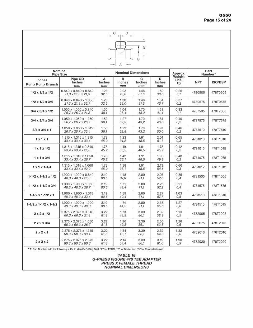
TABLE 18 G-PRESS FIGURE 478 TEE ADAPTER
PRESS X FEMALE THREAD NOMINAL DIMENSIONS
G550Page 16 of 24
Nominal Pipe Size Nominal Dimensions
Approx. Weight
Lbs.kg
Part Number*
InchesPipe OD Inches
mm
A Inches
mm
D Inches
mm
K Inches
mm
N Number of
Holes
L Bolt Hole
Inchesmm
1/2 0.84021,3
1.8547,0
3.7495,0
2.5665,0 4 0.55
141.590,7 475PN16050
3/4 1.05026,7
2.2055,9
4.13105
2.9574,9 4 0.55
142.241,0 475PN16075
1 1.31533,4
2.5264,0
4.52115
3.3585,1 4 0.55
142.691,2 475PN16100
1-1/2 1.90048,3
2.4863,0
5.90150
4.33110 4 0.71
184,432,0 475PN16150
2 2.37560,3
3.4687,9
6.50165
4.92125 4 0.71
186,022,7 475PN16200
* To Part Number, add the following suffix to identify O-Ring Seal: “E” for EPDM, “T” for Nitrile, and “O” for Fluoroelastomer.
Nominal Pipe Size Nominal Dimensions
Approx. Weight
Lbs.kg
Part Number*
InchesPipe OD Inches
mm
A Inches
mm
D Inches
mm
K Inches
mm
N Number of
Holes
L Bolt Hole
Inchesmm
1/2 0.84021,3
1.8547,0
3.5088,9
2.3760,2 4 0.62
15,80.840,4 475050
3/4 1.05026,7
2.2356,6
3.94100,1
2.7569,9 4 0.62
15,81.280,6 475075
1 1.31533,4
2.5264,0
4.33110,0
3.1379,5 4 0.62
15,81.770,8 475100
1-1/2 1.90048,3
3.4086,4
4.92125,0
3.8798,3 4 0.62
15,82.901,3 475150
2 2.37560,3
4.71119,6
5.91150,1
4.75120,7 4 0.75
19,14.652,1 475200
* To Part Number, add the following suffix to identify O-Ring Seal: “E” for EPDM, “T” for Nitrile, and “O” for Fluoroelastomer.
A D K
L
N
A D K
L
N
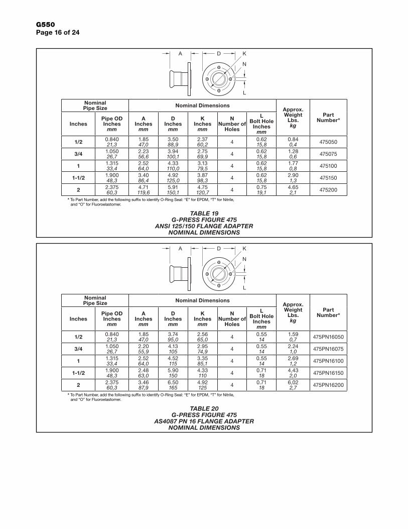
TABLE 20 G-PRESS FIGURE 475
AS4087 PN 16 FLANGE ADAPTER NOMINAL DIMENSIONS
TABLE 19 G-PRESS FIGURE 475
ANSI 125/150 FLANGE ADAPTER NOMINAL DIMENSIONS

G550Page 17 of 24
Nominal Pipe Size
Nominal Dimen-sions Approx.
Weight Lbs.kg
Part Number*
InchesPipe OD Inches
mm
A Inches
mm
1/2 0.84021,3
3.0777,9
0.950,4 466050
3/4 1.05026,7
3.1981,0
1.390,6 466075
1 1.31533,4
3.2783,1
1.840,8 466100
1-1/2 1.90048,3
3.4487,4
2.981,4 466150
2 2.37560,3
4.53115,1
4.792,2 466200
* To Part Number, add the following suffix to identify O-Ring Seal: “E” for EPDM, “T” for Nitrile, and “O” for Fluoroelastomer.
Nominal Pipe Size Nominal Dimensions
Approx. Weight
Lbs.kg
Part Number*
InchesPipe OD Inches
mm
A Inches
mm
D Inches
mm
K Inches
mm
N Number of
Holes
L Bolt Hole
Inchesmm
1/2 0.84021,3
1.8547,0
3.7595,3
2.6467,1 4 0.55
140.900,4 475TE050
3/4 1.05026,7
2.2055,9
3.94100,1
2.8772,9 4 0.55
141.300,6 475TE075
1 1.31533,4
2.5264,0
4.53115,1
3.2783,1 4 0.55
141.830,8 475TE100
1-1/2 1.90048,3
2.4863,0
5.31134,9
3.8698,0 4 0.55
143.031,4 475TE150
2 2.37560,3
3.4687,9
5.91150,1
4.49114,0 4 0.71
184.912,2 475TE200
* To Part Number, add the following suffix to identify O-Ring Seal: “E” for EPDM, “T” for Nitrile, and “O” for Fluoroelastomer.
A
A D K
L
N
TABLE 21 G-PRESS FIGURE 475
BS 10 TABLE E FLANGE ADAPTER NOMINAL DIMENSIONS
TABLE 22 G-PRESS FIGURE 466
ANSI 125/150 FLANGE ADAPTER VAN STONE NOMINAL DIMENSIONS
G550Page 18 of 24
Nominal Pipe Size Nominal Dimensions
Approx. Weight
Lbs.kg
Part Number*
InchesPipe OD Inches
mm
A Inches
mm
B Inches
mmNPT ISO/BSP
1/2 x 1/2 0.840 x 0.84021,3 x 21,3
0.7819,8
2.2156,1
0.150,1 4760505 476T0505
1/2 x 3/4 0.840 x 1.05021,3 x 26,7
0.8020,3
2.3058,4
0.200,1 4760575 476T0575
1/2 x 1 0.840 x 1.31521,3 x 33,4
0.8722,1
2.4462,0
0.340,2 4760510 476T0510
3/4 - 1/2 1.050 x 0.84026,7 x 21,3
0.8120,6
2.3559,7
0.220,1 4767505 476T7505
3/4 x 3/4 1.050 x 1.05026,7 x 26,7
0.8120,6
2.4361,7
0.220,1 4767575 476T7575
3/4 x 1 1.050 x 1.31526,7 x 33,4
0.8722,1
2.5665,0
0.290,1 4767510 476T7510
3/4 x 1-1/4 1.050 x 1.66026,7 x 42,2
0.9022,9
2.6667,6
0.520,2 4767512 476T7512
1 x 3/4 1.315 x 1.05033,4 x 26,7
0.8321,1
2.5264,0
0.280,1 4761075 476T1075
1 x 1 1.315 x 1.31533,4 x 33,4
0.8321,1
2.6467,1
0.320,1 4761010 476T1010
1 x 1-1/4 1.315 x 1.66033,4 x 42,2
0.9223,4
2.7770,4
0.520,2 4761012 476T1012
1 x 1-1/2 1.315 x 1.90033,4 x 48,3
0.9022,9
2.7469,6
0.580,3 4761015 476T1015
1-1/2 x 3/4 1.900 x 1.05048,3 x 26,7
0.9123,1
2.7870,6
0.550,2 4761575 476T1575
1-1/2 x 1 1.900 x 1.31548,3 x 33,4
0.9123,1
2.9073,7
0.620,3 4761510 476T1510
1-1/2 x 1-1/4 1.900 x 1.66048,3 x 42,2
0.9022,9
2.9274,2
0.550,2 4761512 476T1512
1-1/2 x 1-1/2 1.900 x 1.90048,3 x 48,3
0.9022,9
2.9274,2
0.640,3 4761515 476T1515
2 x 1-1/2 2.375 x 1.90060,3 x 48,3
0.9022,9
3.4888,4
0.940,4 4762015 476T2015
2 x 2 2.375 x 2.37560,3 x 60,3
0.9824,9
3.7896,0
1.040,5 4762020 476T2020
* To Part Number, add the following suffix to identify O-Ring Seal: E for EPDM, T for Nitrile, and O for Fluoroelastomer.
A
B
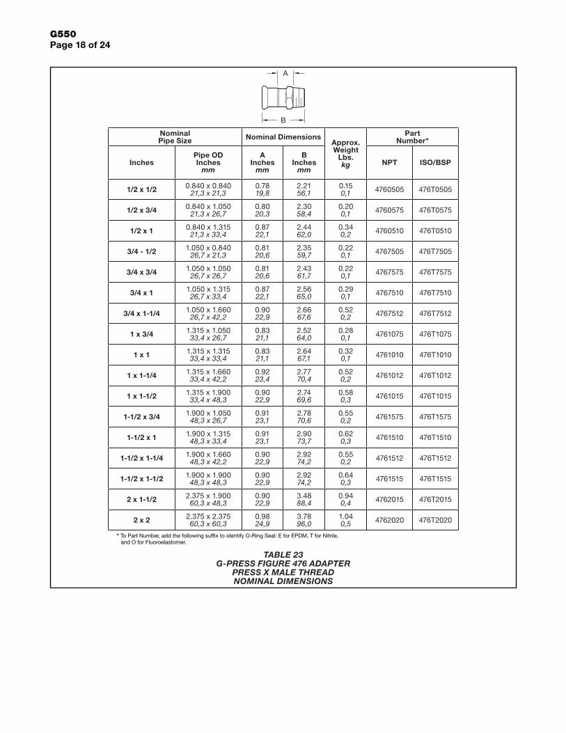
TABLE 23 G-PRESS FIGURE 476 ADAPTER
PRESS X MALE THREAD NOMINAL DIMENSIONS

G550Page 19 of 24
Nominal Pipe Size Nominal Dimensions
Approx. Weight
Lbs.kg
Part Number*
InchesPipe OD Inches
mm
A Inches
mm
B Inches
mmNPT ISO/BSP
1/2 x 1/2 0.840 x 0.84021,3 x 21,3
0.6616,8
2.1755,1
0.280,1 4790505 479T0505
1/2 x 3/4 0.840 x 1.05021,3 x 26,7
0.9223,4
2.4462,0
0.280,1 4790575 479T0575
1/2 x 1 0.840 x 1.31521,3 x 33,4
0.8922,6
2.5665,0
0.430,2 4791510 479T1510
3/4 x 1/2 1.050 x 0.84026,7 x 21,3
0.8421,3
2.4762,7
0.320,1 4797505 479T7505
3/4 x 3/4 1.050 x 1.05026,7 x 26,7
0.7017,8
2.4562,2
0.280,1 4797575 479T7575
3/4 x 1 1.050 x 1.31526,7 x 33,4
0.6616,8
2.5965,8
0.430,2 4797510 479T7510
3/4 x 1-1/4 1.050 x 1.66026,7 x 42,2
1.1027,9
3.0377,0
0.720,3 4791512 479T1512
1 x 1/2 1.315 x 0.84033,4 x 21,3
0.8621,8
2.5665,0
0.500,2 4791005 479T1005
1 x 3/4 1.315 x 1.05033,4 x 26,7
0.8621,8
2.5665,0
0.430,2 4791075 479T1075
1 x 1 1.315 x 1.31533,4 x 33,4
0.7218,3
2.5665,0
0.430,1 4791010 479T1010
1 x 1-1/4 1.315 x 1.66033,4 x 42,2
1.0927,7
2.9574,9
0.690,3 4791012 479T1012
1 x 1-1/2 1.315 x 1.90033,4 x 48,3
1.0526,7
3.1379,5
0.800,4 4791015 479T1015
1-1/2 x 1 1.900 x 1.31548,3 x 33,4
1.0125,7
3.0677,7
1.260,6 4791510 479T1510
1-1/2 x 1-1/4 1.900 x 1.66048,3 x 42,2
0.6616,8
2.7068,6
0.630,3 4791512 479T1512
1-1/2 x 1-1/2 1.900 x 1.90048,3 x 48,3
0.8020,3
3.0577,5
0.640,3 4791515 479T1515
1-1/2 x 2 1.900 x 2.37548,3 x 60,3
1.3935,3
3.6592,7
1.210,5 4791520 479T1520
2 x 1-1/4 2.375 x 1.66060,3 x 42,2
0.8722,1
3.3986,1
1.480,7 4792012 479T2012
2 x 1-1/2 2.375 x 1.90060,3 x 48,3
1.2030,5
3.9099,1
1.830,8 4792015 479T2015
2 x 2 2.375 x 2.37560,3 x 60,3
1.1830,0
3.94100,1
1.040,5 4792020 479T2020
* To Part Number, add the following suffix to identify O-Ring Seal: E for EPDM, T for Nitrile, and O for Fluoroelastomer.
A
B
TABLE 24 G-PRESS FIGURE 479 ADAPTER
PRESS X FEMALE THREAD NOMINAL DIMENSIONS

G550Page 20 of 24
Nominal Pipe Size Nominal Dimensions
Approx. Weight
Lbs. kg
Part Number*
InchesPipe OD Inches
mm
A Inches
mm
B Inches
mm
3/4 x 1/2 1.050 x 0.84026,7 x 21,3
1.2130,7
3.0477,2
0.180,1 4747505
1 x 1/2 1.315 x 0.84033,4 x 21,3
1.3033,0
3.1981,0
0.280,1 4741005
1 x 3/4 1.315 x 1.05033,4 x 26,7
1.7544,5
3.7695,5
0.260,1 4741075
1-1/2 x 1/2 1.900 x 0.84048,3 x 21,3
1.1529,2
3.4286,9
0.330,1 4741505
1-1/2 x 3/4 1.900 x 1.05048,3 x 26,7
1.6040,6
3.5590,2
0.550,2 4741575
1-1/2 x 1 1.900 x 1.31548,3 x 33,4
2.0351,6
4.25108,0
0.370,2 4741510
2 x 1/2 2.375 x 0.84060,3 x 21,3
1.6241,1
4.23107
0.530,2 4742005
2 x 3/4 2.375 x 1.05060,3 x 26,7
1.5940,4
4.34110
0.350,2 4742075
2 x 1 2.375 x 1.31560,3 x 33,4
1.5539,4
4.37111
0.570,3 4742010
2 x 1-1/2 2.375 x 1.90060,3 x 48,3
1.7945,5
4.77121
0.700,3 4742015
* To Part Number, add the following suffix to identify O-Ring Seal: “E” for EPDM, “T” for Nitrile, and “O” for Fluoroelastomer.
B
A
TABLE 25 G-PRESS FIGURE 474 REDUCER MALE PRESS X FEMALE PRESS
NOMINAL DIMENSIONS

G550Page 21 of 24
Nominal Pipe Size Nominal Dimensions Approx.
Weight Lbs.kg
Part Number*
InchesPipe OD Inches
mm
A Inches
mm
B Inches
mm
1/2 0.84021,3
2.3559,7
4.02102
0.620,3 485050
3/4 1.05026,7
2.6467,1
4.54115
0.820,4 485075
1 1.31533,4
2.7269,1
4.76121
0.970,4 485100
1-1/2 1.90048,3
3.8898,6
6.29160
2.361,1 485150
2 2.37560,3
4.72120
8.26210
3.701,7 485200
* To Part Number, add the following suffix to identify O-Ring Seal: “E” for EPDM, “T” for Nitrile, and “O” for Fluoroelastomer.
Nominal Pipe Size Nominal Dimensions Approx.
Weight Lbs.kg
Part Number*
InchesPipe OD Inches
mm
A Inches
mm
B Inches
mm
1/2 0.84021,3
0.7218,3
1.5639,6
0.090,1 484050
3/4 1.05026,7
0.7920,1
1.7444,2
0.130,1 484075
1 1.31533,4
0.8321,1
1.8547,0
0.180,1 484100
1-1/2 1.90048,3
0.9524,1
2.1554,6
0.330,1 484150
2 2.37560,3
1.1429,0
2.9173,9
0.550,2 484200
* To Part Number, add the following suffix to identify O-Ring Seal: “E” for EPDM, “T” for Nitrile, and “O” for Fluoroelastomer.
B
A
A
B
TABLE 26 G-PRESS FIGURE 484 END CAP
NOMINAL DIMENSIONS
TABLE 27 G-PRESS FIGURE 485 UNION
NOMINAL DIMENSIONS

G550Page 22 of 24
Nominal Pipe Size Nominal Dimensions Approx.
Weight Lbs.kg
Part Number*
InchesPipe OD Inches
mm
A Inches
mm
B Inches
mm
C Inches
mm
D Inches
mm
E Inches
mm
3/4 1.05026,7
0.62515,9
0.3137,9
0.93823,8
1.5739,9
4.94126
0.320,1 477075
1 1.31533,4
0.62515,9
0.3137,9
1.19030,2
1.1830,0
5.02128
0.420,2 477100
1-1/2 1.90048,3
0.62515,9
0.3137,9
1.77545,1
1.5739,9
5.20132
0.640,3 477150
2 2.37560,3
0.62515,9
0.3137,9
2.25057,2
2.3659,9
5.77147
0.870,4 477200
* To Part Number, add the following suffix to identify O-Ring Seal: “E” for EPDM, “T” for Nitrile, and “O” for Fluoroelastomer.
Nominal Pipe Size Nominal Dimensions Approx.
Weight Lbs.kg
Part Number*
InchesPipe OD Inches
mm
E Inches
mm
U Inches
mm
1/2 0.84021,3
5.13130
4.00102
0.250,1 461050
3/4 1.05026,7
5.27134
4.00102
0.330,1 461075
1 1.31533,4
5.34136
4.00102
0.420,2 461100
1-1/2 1.90048,3
5.52140
4.00102
0.650,3 461150
2 2.37560,3
6.09155
4.00102
0.920,4 461200
* To Part Number, add the following suffix to identify O-Ring Seal: “E” for EPDM, “T” for Nitrile, and “O” for Fluoroelastomer.
U
E
E
AD
C
B
TABLE 29 G-PRESS FIGURE 477 TRANSITION NIPPLE
MALE PRESS X GROOVED NOMINAL DIMENSIONS
TABLE 28 G-PRESS FIGURE 461 WELD ADAPTER
FEMALE PRESS X MALE WELD NOMINAL DIMENSIONS
G550Page 23 of 24
Ordering ProcedureGRINNELL Products are available globally through a network of distribu-tion centers. Visit www.grinnell.com for the nearest distributor.
When placing an order, indicate the full product name, size, O-Ring Seal type, and quantity.
Add the appropriate suffix to the part number identifying O-Ring Seal: “E” for EPDM, “T” for Nitrile, and “O” for Fluo-roelastomer (e.g., 407050E).
Separately Ordered O-Rings Replacement PartsEPDM1/2 Inch . . . . . . . . . . . . . . . . . . . . 05SSPRESSE3/4 Inch . . . . . . . . . . . . . . . . . . . . 08SSPRESSE1 Inch . . . . . . . . . . . . . . . . . . . . . . .10SSPRESSE1-1/2 Inch . . . . . . . . . . . . . . . . . . . .15SSPRESSE2 Inch . . . . . . . . . . . . . . . . . . . . . . .20SSPRESSE
NITRILE1/2 Inch . . . . . . . . . . . . . . . . . . . . .05SSPRESST3/4 Inch . . . . . . . . . . . . . . . . . . . . .08SSPRESST1 Inch . . . . . . . . . . . . . . . . . . . . . . .10SSPRESST1-1/2 Inch . . . . . . . . . . . . . . . . . . . .15SSPRESST2 Inch . . . . . . . . . . . . . . . . . . . . . . .20SSPRESST
FLUOROELASTOMER1/2 Inch . . . . . . . . . . . . . . . . . . . . 05SSPRESSO3/4 Inch . . . . . . . . . . . . . . . . . . . . 08SSPRESSO1 Inch . . . . . . . . . . . . . . . . . . . . . . 10SSPRESSO1-1/2 Inch . . . . . . . . . . . . . . . . . . . 15SSPRESSO2 Inch . . . . . . . . . . . . . . . . . . . . . . 20SSPRESSO

Copyright © 2017 Tyco Fire Products, LP. All rights reserved.
GLOBAL HEADQUARTERS | 1400 Pennbrook Parkway, Lansdale, PA 19446 | Telephone +1-215-362-0700
G550Page 24 of 24