
GRATIS REPORT
22
KWAME NKRUMAH UNIVERSITY OF SCIENCE AND TECHNOLOGY MATERIALS/METALLURGICAL ENGINEERING DEPARTMENT June – July ,2016 A REPORT ON INDUSTRIAL ATTACHMENT AT GRATIS FOUNDATION HEAD OFFICE – TEMA BY: ADDO FRANCIS KWAME POLYCARP
-
Upload
francis-addo -
Category
Documents
-
view
20 -
download
1
Transcript of GRATIS REPORT

KWAME NKRUMAH UNIVERSITY OF SCIENCE AND
TECHNOLOGY
MATERIALS/METALLURGICAL ENGINEERING
DEPARTMENT
June – July ,2016
A REPORT ON INDUSTRIAL ATTACHMENT AT GRATIS FOUNDATION HEAD OFFICE – TEMA
BY: ADDO FRANCIS KWAME POLYCARP

BY: ADDO FRANCIS KWAME POLYCARP
A REPORT ON INDUSTRIAL ATTACHMENT
AT GRATIS FOUNDATION
Table of Contents
A REPORT ON INDUSTRIAL ATTACHMENT AT GRATIS FOUNDATION ..................................................... 1
AKNOWLEDGEMENT............................................................................................................................ 2
ABSTRACT.............................................................................................................................................. 3
ABOUT GRATIS FOUNDATION .......................................................................................................... 4
VISION ..................................................................................................................................................... 4
MISSION .................................................................................................................................................. 4
WEEK ONE – METAL MACHINING LAB ........................................................................................... 5
CENTRE LATHE MACHINE ..................................................................................................................... 5 GRINDING MACHINE .............................................................................................................................. 6 DRILLING MACHINE ............................................................................................................................... 7 ROLLER MACHINE ................................................................................................................................... 8 ENGRAVING MACHINE/ PANTOGRAPH .............................................................................................. 9 MAKING A SCREW THREAD FOR A METAL ......................................................................................... 9 MILLING MACHINE ............................................................................................................................... 10
WEEK 2: WELDING AND FABRICATION .........................................................................................12
ARC WELDING..........................................................................................................................................12 OXY – ACETYLENE WELDING...............................................................................................................13
GRINDING MACHINE ......................................................................................................................... 14 BENDING MACHINE ............................................................................................................................15 HYDRAULIC SHEAR MACHINE ....................................................................................................... 16
WEEK THREE: FOUNDRY .................................................................................................................. 17
WEEK FOUR: ENGINEERING DESIGN CENTRE .......................................................................... 18
THE DESIGN PROCESS ...................................................................................................................... 19 DESIGNING WITH AUTOCAD ........................................................................................................... 19
CONCLUSION....................................................................................................................................... 20
REFERENCE ......................................................................................................................................... 20
BY: ADDO FRANCIS KWAME POLYCARP
AKNOWLEDGEMENT
My gratitude first of all goes to the almighty God for his enlightenment
and wisdom upon me during the course of my attachment.
My appreciation also goes to Mr. Emmanuel Asiedu, CEO of GRATIS
Foundation, Mr. Ekow Andoh (officer in – charge of recruitment), Mrs.
Lucy Kpor (Training Officer), Mr. Gabriel Boateng – Appiah (Design
Engineering officer) and all other trainers and apprentices who in
various ways helped in imparting practical knowledge unto me.

BY: ADDO FRANCIS KWAME POLYCARP
ABSTRACT
Industrial attachment is an integral part of student training in the university. I
had my internship at GRATIS foundation. Work at GRATIS starts at 8am and
ends at 5pm. On our first day we were taken through the activities, departments
and general knowledge of GRATIS foundation. The departments are:
Metal machining workshop
Welding and Fabrication workshop
Foundry
Engineering Design Centre
We were divided into four groups of six students each and were expected to
spend one full week in department and after, assigned to another department.
BY: ADDO FRANCIS KWAME POLYCARP
ABOUT GRATIS FOUNDATION
GRATIS Foundation was established in March 1987; initially as Ghana Regional
Appropriate Technology Industrial service (GRATIS), a project to promote
micro – industrial activities. Gratis Foundation is a leader in designing,
manufacturing and selling of precision agro, food processing and sanitation
equipment. Some of their products are
Yam slicer
Fruit washer
Fruit Juice Extractor
Palm fruit digester
Fufu pounding machine
Flour mixer
VISION
To be a Centre of excellence for research and Innovation for
appropriate technology product and services in Africa.
MISSION
To Research, design, develop, manufacture and market appropriate
technology – based products and services for micro, small and
medium enterprises so as to facilitate socio – economic and industrial
development in Ghana and other countries.

BY: ADDO FRANCIS KWAME POLYCARP
WEEK ONE – METAL MACHINING LAB
CENTRE LATHE MACHINE Popularly known as the “mother of machine tools” the lathe is a machine used to
cut screws, bore holes, facing and almost any work on a machine part.
Some of the parts of a centre lathe are
Apron: holds the tool holder
Head stock: contains the chuck, spindle and controls of the machine
Tail stock: used to support work piece when drilling
Tool holder: the tools are placed in them
Roller: a cylindrical bar attached to the revolving center
Revolving center: it is placed in the tail and attached to the roller
Bed: apron sits and slides on it.
Figure 1: centre lathe machine
The various tools used on the lathe also are;
HSS Tool: for machining hard or high carbon
TIP Tool: machining circular parts and also facing
BORING Tool: for boring holes in work

BY: ADDO FRANCIS KWAME POLYCARP
PARTING Tool: for separating or dividing work into two.
Figure 3: HSS tool
Figure 4: TIP tool
Figure 5: PARTING tool
The tip tool was used to smoothen a galvanized imperfectly round part into a
perfect round shape and also reduce to a fixed diameter. The part will be used as
a cutter in a fufu pounding machine.
GRINDING MACHINE
A machine used to smoothen the surface of a work piece.
It has a magnetic stage that is holds work to be machined in place.
Figure 2: Boring tool

BY: ADDO FRANCIS KWAME POLYCARP
It uses a wheel as the cutting tool, usually as a finisher in fabrication works.
It has a bed with a fixture to hold and guide the work piece. I observed the
grinding machine being used to smoothen the surface of an engine part.
Figure 6: Grinding machine
DRILLING MACHINE The machine is used to drill holes in a work piece.
The drill machines were many but we used one of them to drill holes into steel
balls. Theses steel balls are used in mills at mine sites and cement factories as
grinding media. The holes are used to check the size at which the balls become
useless as they wear out. In the process of drilling, the tip of the drill tool was
allowed to generate some amount of heat before drilling through the workpiece,
this was because the balls are made of still which is a very hard and metal.
The drill had three buttons used to operate the drilling.
The anti-clockwise drill button is used to push the drill into the workpiece.
The clockwise drill button is used to remove the drill from the workpiece
in case it gets stuck in the work piece.
The red button on the head part is used to stop the rotation and drilling
action of the tool.
BY: ADDO FRANCIS KWAME POLYCARP
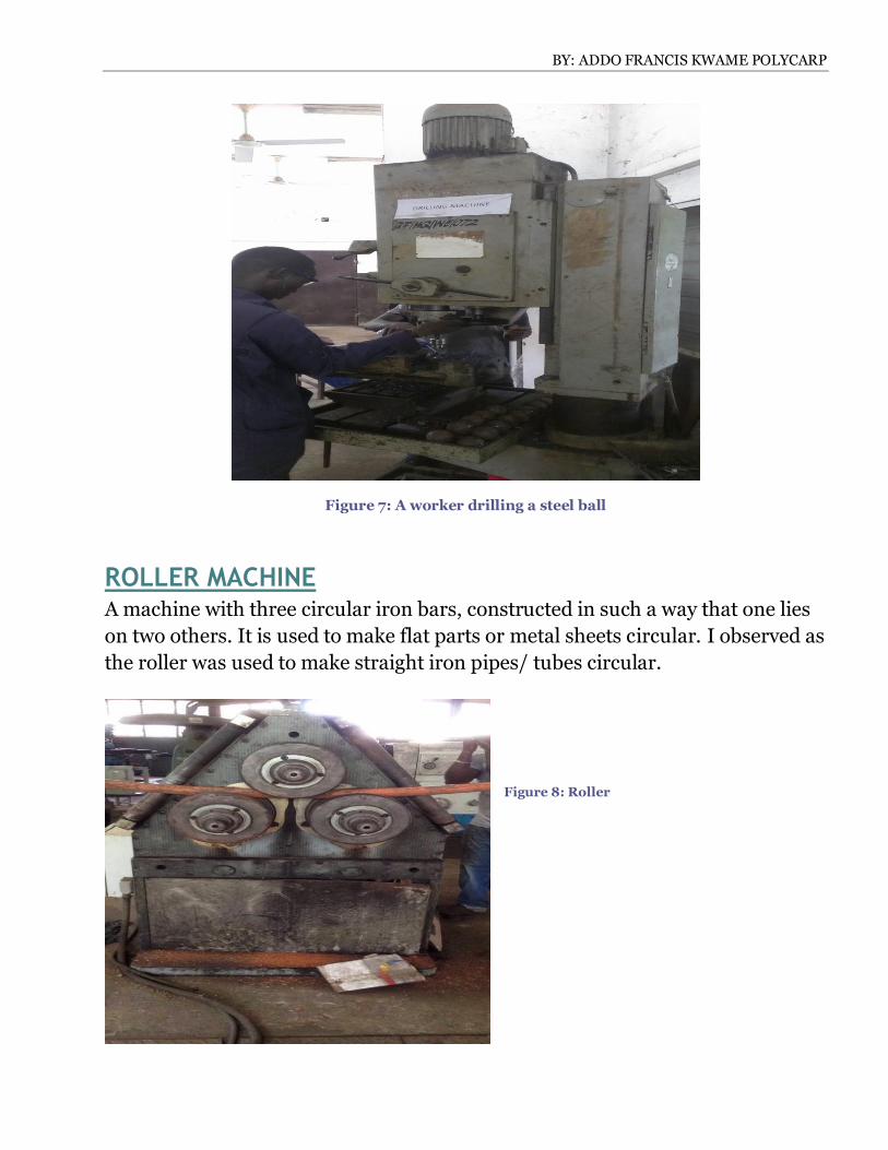
Figure 7: A worker drilling a steel ball
ROLLER MACHINE A machine with three circular iron bars, constructed in such a way that one lies
on two others. It is used to make flat parts or metal sheets circular. I observed as
the roller was used to make straight iron pipes/ tubes circular.
Figure 8: Roller

BY: ADDO FRANCIS KWAME POLYCARP
ENGRAVING MACHINE/ PANTOGRAPH
A machine used to engrave letters, words and lines on a metal plate. It uses a
sharp pointed tool (engraver) to etch the metal and form the desired pattern.
One passes over a small metal with the desired shape and the other point with
the cutting tip engraves the design unto the workpiece.
It was used by an operator to calibrate a piece of metal sheet which would be
used as a measuring tool.
Figure 9: pantograph
MAKING A SCREW THREAD FOR A METAL Threads are grooves that form a spiral in or outside a cylinder and usually used
as fasteners for assembling components.
There are two ways of threading a workpiece.
Internal threading (Tapping): the cutting tool is called a Tap. In this
process a cylindrical tool with cutting teeth arranged in a spiral whose
pitch is equal to that of the screw threads, is simultaneously rotated and

BY: ADDO FRANCIS KWAME POLYCARP
fed into a pre-existing hole. The tap is a solid piece and the tapping
operation is performed on a drill press equipped with a tapping head,
which allows penetration into the hole at a rate that corresponds to the
screw pitch. At the end of the operation, the spindle rotation is reversed so
the tap can be unscrewed from the hole.
External threading (Dicing): the cutting here is called threading die. To cut
an external thread, the die is rotated around the starting cylindrical stock
of the proper diameter, beginning at one end and proceeding to the other
end. The cutting teeth at the opening of the die are tapered so that the
starting depth of cut is less at the beginning of the operation, finally
reaching full thread depth at the trailing side of the die. The pitch of the
threading die teeth determines the pitch of the screw that is being cut.
The pitch of a thread is determined by a thread gauge.
Work is lubricated with palm oil.
Figure 10: threading die
MILLING MACHINE Milling is a machining operation in which a work piece is fed past a rotating
cylindrical tool with multiple cutting edges. The cutting tool in milling is called a
milling cutter and the cutting edges are called teeth.
The knee-and-column milling machine is the machine tool for milling at
GRATIS. It is available as either horizontal or vertical milling machine; the

BY: ADDO FRANCIS KWAME POLYCARP
horizontal type has an arbor which supports the cutter. The arbor is basically a
shaft that is connected to the spindle and supports the cutter.
The milling machine is used to cut screw threads, keyways gears etc.
There are two main classes of milling these are face milling and peripheral
milling. In peripheral milling, the axis of the tool is parallel to the surface being
machined, and the operation is performed by cutting edges on the outside
periphery of the cutter.
In face milling, the axis of the cutter is perpendicular to the surface being milled,
and machining is performed by cutting edges on both the end and outside
periphery of the cutter.
Figure 11: Horizontal milling machine

BY: ADDO FRANCIS KWAME POLYCARP

BY: ADDO FRANCIS KWAME POLYCARP
WEEK 2: WELDING AND FABRICATION
Welding is a materials joining process in which two or more parts are fitted at
their contacting surfaces by a suitable application of heat and/or pressure. In
some welding processes a filler material is added to facilitate coalescence.
We were taken around the welding shop and shown the:
Arc welding equipment
Bending machine
Oxy – acetylene welding equipment
Grinding machine.
Welding at GRATIS is usually done using the fusion process. Fusion-welding
processes use heat to melt the base metals. In many fusion welding operations, a
filler metal is added to the molten pool to facilitate the process and provide bulk
and strength to the welded joint.
The fusion weld is subdivided into 3 groups two of which I witnessed at
GRATIS. These were: arc – welding (AW) and oxyfuel gas welding (OFW).
ARC WELDING Arc welding refers to a group of welding processes in which heating of the
metals is accomplished by an electric arc, some arc welding operations also
apply pressure during the process and most utilize a filler metal.
An electric arc is a discharge of electric current across a gap in a circuit. It is
sustained by the presence of plasma through which current flows. To initiate the
arc in an AW process, the electrode is brought into contact with the work and
then quickly separated from it by a short distance. The electric energy from the
arc thus formed produces temperatures of 5500_C (10,000_F) or higher,
sufficiently hot to melt any metal. A pool of molten metal, consisting of base
metal(s) and filler metal (if used) is formed near the tip of the electrode. In most
arc welding processes, filler metal is added during the operation to increase the
volume and strength of the weld joint. As the electrode is moved along the joint,
the plasma solidifies after it. Movement of the electrode is done by the welder
and one of the difficulties in this process is that, the quality of the weld depends

BY: ADDO FRANCIS KWAME POLYCARP
on the skills of the welder. I was given the chance to try welding some few parts
together using the shielded metal arc welding(SMAW) process and some of the
corrections and observations I made were
The metal parts were made of mild steel, since every electrode has the type
of metal it is used for in Arc welding; I used the mild steel electrode with
specifications (MT – 12E6019).
The voltage set is determined by the type of metal being welded and its
hardness.
The type of joint worked on was the close butt joint.
When welding the electrode should not touch the workpiece, it causes the
electrode to stick unto the work piece and no plasma is formed.
The electrode should not be too far from the workpiece because the
electrode would melt and just pour unto metal joint without actually
joining them together. This gives a poor quality or weak joint/weld.
The electrode is moved very slowly on the workpiece and should not be
passed in reverse.
The specification on the electrode had its meaning. The E represents
electrode, the first two letters represent the tensile strength(in psi), the
third digit indicates the position of the weld(all positions in this case) and
the fourth digit indicates the type of electrode coating and the type of
power supply used.
Figure 12: arc welding process
Other arc welding processes are the metal inert gas welding (MIG) and the
Tungsten inert gas welding (TIG), generally known as the Gas metal arc welding
(GMAW). TIG welding makes use of tungsten as the electrode due to it high

BY: ADDO FRANCIS KWAME POLYCARP
strength, and in the MIG welding other metals such as aluminum, copper etc.
are used but the difference here is that inert gas such as helium or argon are
used to accomplish shielding of the arc.
OXY – ACETYLENE WELDING Oxyacetylene welding (OAW) is a fusion-welding process performed by a high-
temperature flame from combustion of acetylene and oxygen. The flame is
directed by a welding torch. The combination of acetylene and oxygen is highly
flammable and very dangerous to use. Sometimes, a filler metal is used and this
filler has to have a composition similar to the metals being welded, this filler is
also coated with a flux that helps to clean the surfaces and prevent oxidation,
thus creating a better weld joint.
GRINDING MACHINE Unlike the grinding machine in the metal machining lab, the grinding tool in the
welding lab is a small hand – held device, used to polish or smoothen the
surface of a work piece. Other uses are:
To remove weld tackings
To cut metal parts
To smoothen welded surfaces
In cutting the workpiece, the flat large plate is used as the cutting tool and to
grind surfaces, the curved small plate is used.
Some of the techniques I learnt were that:
The guide has to be on always. If the guide is not properly fixed in place,
the machine should not be used since the plate can shatter at any time and
considering the speed of rotation, it can cause serious damages such as
injuries and even death.
The cutting tool should be properly fixed and not wobble to ensure ease of
use and perfect cutting.
Positioning is also important to avoid injuries by the tool or sparks.

BY: ADDO FRANCIS KWAME POLYCARP
Eye protection must be worn always to protect eyes against the sparks.
To avoid mistakes in cutting, the pattern should be drawn with a writing
tool (chalk), and then the grinder is used to mark out slightly the pattern
before being pressed on the work to cut it out.
Figure 13: grinder
BENDING MACHINE Bending machine is a machine that is used to form bends on a work piece while
assembling.
The universal bending machine is what is used at GRATIS foundation.
It consists of a basic machine that can be adjusted to get various angles of bends.
The tools are easily exchanged on a plug – in system and have a programming
that is used in operation.
The programming is displayed on a graphical user interface (GUI) that is
attached to the machine.
To operate it:
The desired angle is set on the GUI
The appropriate tool is fixed
The work piece is positioned and the tool slowly lowered onto the work
piece to bend it to required angle.

BY: ADDO FRANCIS KWAME POLYCARP
HYDRAULIC SHEAR MACHINE A powerful tool that is used for a quick cut– through of work pieces. It is
powered by electricity but can only function with the use of hydrogen gas and a
hydraulic fluid.
It consists of the shear table, work – holding device, upper blade (cutting blade).
To operate, the metal is placed on the table and then the cut length indicated
and placed directly under the upper blade. The force is then set according to the
thickness of the metal to be cut, for a good shear (a thickness of 4mm will be set
at 5mm).

BY: ADDO FRANCIS KWAME POLYCARP
WEEK THREE: FOUNDRY
A foundry is a place where metal castings are made and this was where we were
assigned on our third week.
Casting which is the main work done here, is a method of heating metal into
liquid and then pouring this liquid into prepared molds. There were furnaces
also for drying pieces and those for heating metal parts to high temperatures.
During my time, there was no metal cast but I learnt from a previous week’s
activity when an aluminum cast was made.
The mold which had four slab holes made with fine sand was prepared
The metal was heated to liquid
The molten metal was then poured into the mold and then covered, with the
edges tightly sealed with clay
This is done for a slow cooling that is devoid of imperfections in the grains.
Casting is one of the oldest metal working processes and is usually used for
complex metal works that would be expensive with other methods.
BY: ADDO FRANCIS KWAME POLYCARP
WEEK FOUR: ENGINEERING DESIGN
CENTRE
This was the last department we were assigned to. In this department we were
thought the design process, how to design using auto cad and also how to plan
the costing.
THE DESIGN PROCESS Before a good design can be made there are some steps that are taken by the
designer and other stakeholders involved to ensure a product that is durable and
also competitive on the market. The steps considered are:
Need
Research(internet, industries and text books)
Concept evaluation and testing (sketches and drawing, criteria tables)
Skin design( assembly drawing and dimensions)
CAD work( computer aided design and drafting, modelling, formatting
and assembly)
Manufacturing of prototype
Testing of prototype
Marketing
The above steps need to be followed meticulously and incase of any problem
indicated at any stage, it should be referred back to the right stage for
corrections to be made before being taken unto the market. For engineering
products, trade fairs are usually the best places to exhibit ready products first
going to the products since buyers can at these fairs evaluate and give the right
views of consumers for any corrections to be made. This would make the
products meet the demand of consumers and accrue a lot of profit.
DESIGNING WITH AUTOCAD

BY: ADDO FRANCIS KWAME POLYCARP
We used the Autodesk mechanical 2006 for auto cad tutorial. We designed an
extruder.
The first thing we did was to create a folder for the whole tutorial and also
subfolders for the parts, subassemblies and the main assembly. We then went
through the steps of using the software to
create and edit the design.
Figure 15: FORMATED DESIGN
We then after designing the extruder, made the costing analysis and that is
shown in the figure below.
Figure 16: costing of extruder
Figure 14: 4- VIEW OF EXTRUDER

BY: ADDO FRANCIS KWAME POLYCARP
CONCLUSION
I would say it was a fun experience and I hope to have more of such practical
exposure in the course of my studies. The overall atmosphere was good and very
inviting for us the interns as the workers and workshop apprentices made time
to answer all of our question to the best of their knowledge and gave us great
advices that we can use in our lives as engineers. The sense of time timing as we
had to sign in and out also helped us to feel as though we were part of them and
also made us time conscious so as not be late to work but always punctual. I
would always love to come back.
REFERENCE
Fundamentals of modern manufacturing (4th edition) (Mikell P. Groover)