Graduate Student Mentor: Dr. Cable Kurwitz Faculty Advisor: Dr. Fred Best NASA Advisor: Art Vasquez...
31
Graduate Student Mentor : Dr. Cable Kurwitz Faculty Advisor : Dr. Fred Best NASA Advisor: Art Vasquez Multiphase Flow in Simulated PEM Fuel Cell Under Variable Gravity Conditions PEM Fuel Cell Team (PEMFCT) Team Member Classification Major Ernie Everett Senior MEEN Nikhil Bhatnagar Junior AERO Christie Tipton Junior BMEN Trevor Bennett Freshman AERO Caitlin Riegler Freshman AERO
-
Upload
aubrey-miles -
Category
Documents
-
view
219 -
download
0
Transcript of Graduate Student Mentor: Dr. Cable Kurwitz Faculty Advisor: Dr. Fred Best NASA Advisor: Art Vasquez...

Graduate Student Mentor: Dr. Cable KurwitzFaculty Advisor: Dr. Fred BestNASA Advisor: Art Vasquez
Multiphase Flow in Simulated PEM Fuel Cell Under Variable Gravity Conditions
PEM Fuel Cell Team (PEMFCT)
Team Member Classification Major
Ernie Everett Senior MEEN
Nikhil Bhatnagar Junior AERO
Christie Tipton Junior BMEN
Trevor Bennett Freshman AERO
Caitlin Riegler Freshman AERO

Background Objectives
- NASA’s Needs - SEI Goals
Review of Fall Work Preliminary Analysis Review of Spring Work Ground Testing
Set Up Manufacturing PSA
Preliminary Modeling Results New Direction Conclusions

Typical fuel cells generate electricity by combining a fuel and oxidizer in the presence of an electrolyte
Main parts of a fuel cell– Flow channels for fuel and oxidizer– Anode and Cathode separated by an
electrolyte Fuel and oxidizer react to produce
electricity and byproducts Fluid distribution and control is a
critical issue with fuel cell operation The parallel flow channels and parallel
plates can produce flow instabilities leading to degraded fuel cell operation and possible damage
Goal –Identify regions of operation where instabilities can occur

NASA’s Need Utilized fuel cells in Gemini, Apollo, and currently in Space Shuttle NASA plans to utilize fuel cells in Constellation program Technology has many other applications
▪ Vehicles, buildings, and alternative energy applications
Purpose Evaluate flow conditions that lead to unstable operation within a
prototypic fuel cell geometry Develop a flow map that describes stable and unstable operating
regions Provide simple modeling approach to predict transition from stable to
unstable operation
Learning Objectives: Understand two-phase fluid flow Identify and understand the flow conditions that produce instabilities

Literature Review Understood fuel cells and the flow distribution
during operation as well as flow anomalies Researched standard geometries and flow rates
▪ Confirmed with NASA Advisor Developed CAD drawings of two cell
geometries Performed stress and flow analysis for both
parallel and serpentine configurations Built simple cells for ground testing Proposed testing to Microgravity University
Parallel PlateGas Used: NitrogenMass Flow Rate: 3 SLPMInlet Pressure: 50 psigInlet Temperature: 293.2 KMax Channel Velocity: 0.1 m/s

Serpentine PlateGas Used: NitrogenMass Flow Rate: 3 SLPMInlet Pressure: 50 psigInlet Temperature: 293.2 KMax Channel Velocity: 0.35 m/s

Serpentine ModelParallel Model
Parallel Model Delta Pressure: 10 Pa Serpentine Model Delta Pressure: 56 Pa
Gas Used: NitrogenMass Flow Rate: 3 SLPMInlet Pressure: 50 psigInlet Temperature: 293.2 K

Maximum Stress: 834.9 psiLocated over channel/plenum junction.Maximum Displacement: <1 micronLocated at lid over the plenum.Minimum Factor of Safety: 36
Maximum Stress: 274.3 psiLocated at center of channel/plenum junction.Maximum Displacement: 10.82 micronsLocated over the center of the plenum.Minimum Factor of Safety: 110

Allows undergraduate teams to carryout flight testing of experiments in microgravity conditions - Submitted Proposal - Completed Safety Analysis - Pursued Funding - Education Outreach
Team Proposal Turned Down Switch from NASA to Zero-G aircraft greatly reduced
the number of experiments

Looked for alternative flight opportunities FAST Program – decided not to pursue
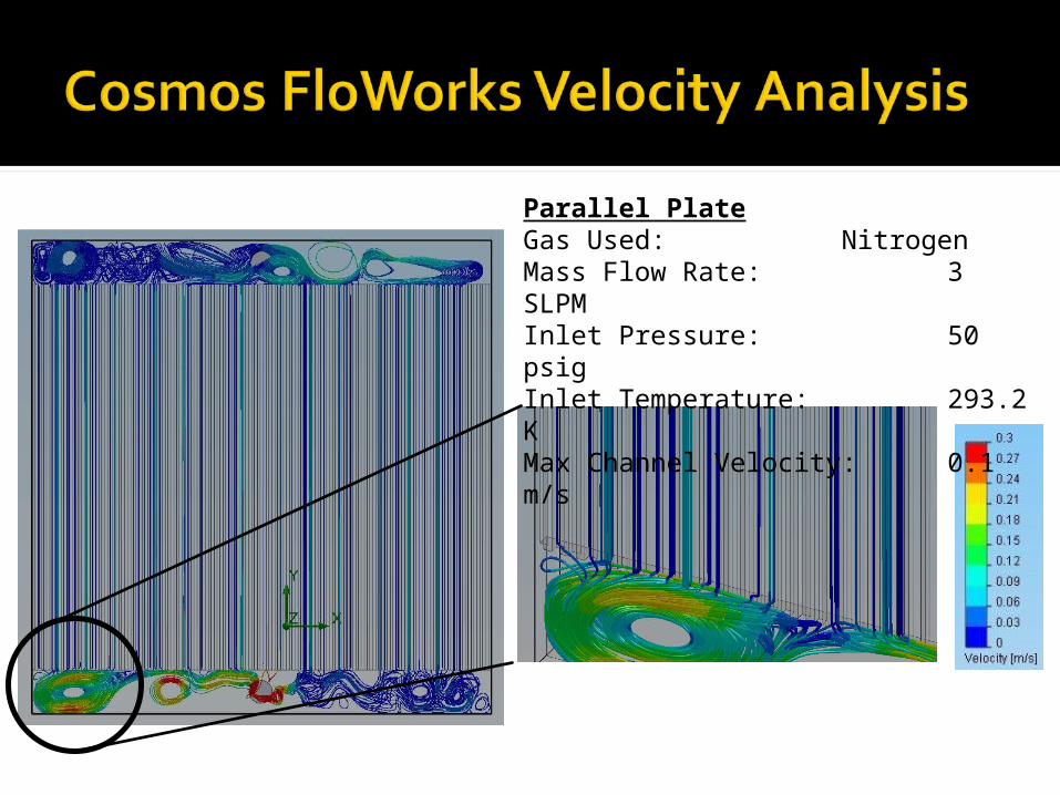
Designed and fabricated a higher fidelity prototype to more accurately reflect fuel cell flow distribution Uniform liquid addition throughout each channel
Built test loop for ground testing Composed and submitted PSA Performed preliminary testing and analysis
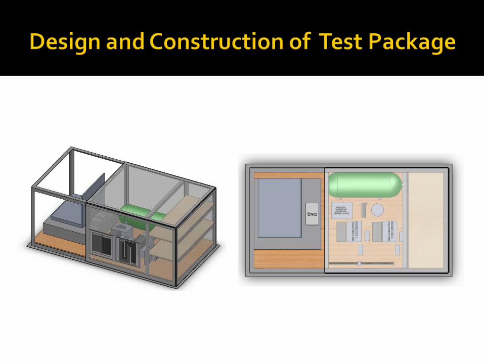
Zoomed in View
Dimensions: 20 cm x 20 cm x 1 cmChannel Dimensions: 1 mm x 1mmNumber of Channels: 80 Wetted Surface Area: 10,700 mm^3NASA interest fueled by these being the standard geometries for fuel cells (based on chemical properties)

Zoomed in View
Dimensions: 20 cm x 20 cm x 1 cmChannel Dimensions: 1 mm x 1mmNumber of Channels: 20 Wetted Surface Area: 10,700 mm^3

•Added a liquid plenum for water introduction from the bottom
•6 mm deep
•Added holes along the channels connecting the lumen of the channels to the liquid plenum
•Changed water input to directly in the center for more uniform addition


Specifications• Gas provided by high pressure Nitrogen Tank• Regulated to 50 psig • Pressure Transducer will monitor pressure drop• Parallel Mass flow meters will simulate excess cells• CCD Digital Camcorders will record fluid instabilities• Vortex Water Separator will separate fluid from gas
Fuel Cell Flow Loop Schematic
Cell Plate
NitrogenTank
Regulator
Pressure Relief Valve
Check Valve
Pressure Transducer
CCD Camera With LED
Back Pressure Regulator
Open Vent
Legend
Syringe Pump
Output water and gas
Plug Valve
Drain
Flow Meter
V-39
V-40


Flow Loop Consists of 2 Flow Meters, Pressure Gauge, Differential Pressure Transducer, and CCD
Gas Flow Provided by Compressed Nitrogen Cylinder and Water Flow Provided by Liquid Syringe Pump
Test Stand Allows Cell Plate to be Rotated
PSA Written and Provided to Safety Officer

Data is collected by video, flow meter and pressure gauge
Varied flow rate on primary flow meter from 0 to 10 sLPM
Bypass Flow Rate Varied from 0 to 90% of Primary Flow
Liquid Flow Rate 0 to 100 cc/min Variation in gas and liquid flow rates
occurred simultaneously


Flow instabilities occur at all flow rates tested for parallel and serpentine channel fuel cell plates Oscillations are small and focused toward exit
of channels Overall liquid holdup is constant for each test
but varies over range of testing with large amounts of water held at low gas flow rates
Some channels occluded for duration of tests (No flow)

Liquid holdup in channels varied with tilt angle on test article Due to flow regime and hydrostatic
pressure changes Indicates a need for reduced gravity
testingTwo-phase flow in outlet line seemed
to have an effect on bypass flow

Liquid pores too large allowing gas to enter liquid plenum at high channel differential pressure
Graded pores or a more controlled method of adding water to better simulate water production is needed
New test setup required to accommodate water entering bypass flow meter

- Engineering Skills:▪ Analysis Tools
▪ Solid Works, Cosmos FloWorks, CosmosWorks, Microsoft Visio▪ Analytic techniques to validate computation▪ Analysis of test data (i.e. model fitting)
▪ Lab Skills:▪ Machining experience▪ Interpreting engineering drawings▪ Developing procedures▪ Carrying out test
▪ Education Outreach▪ Teamwork

Purpose: -Evaluate flow conditions within a prototypic fuel cell geometry
- Determine a range of stable operations for given flow and environmental conditions
Ground testing showed occlusions have a great gravitational dependence and that more work needs to be done on our test system

Replace flow meter to complete ground test matrix
Modify test stand to allow higher flow rates
Modify liquid addition method to provide a more uniform liquid addition
Continue work on test loop and develop more robust analysis techniques


Parallel channel instability may occur when a number of channels are connected at common headers.
Although the total flow remains constant, flow oscillations may occur in some of the channels.
Nonlinear transient momentum equations can be used to solve for several channels by integrating the momentum equation along each channel.
Fluid properties used in the momentum equations are obtained from the energy equation and the equation of state.
The modeling is very complex , the following equations convey the complexity
After integrating the momentum equations for the channels, the equations are solved simultaneously.

Starting with the Momentum Equation
Define B and C
We Simplify

The Total Inlet Flow
Differentiating
We can then Solve n Equations to Determine the Channel Flow Rate


![[XLS] · Web viewVASQUEZ BERRIO ADA FELICIA VASQUEZ BURGOS CALIXTO VASQUEZ CABANILLAS JAIME LINDORFIO VASQUEZ CHACCHI CELESTINO ...](https://static.fdocuments.us/doc/165x107/5adf46a67f8b9a5a668c07d3/xls-viewvasquez-berrio-ada-felicia-vasquez-burgos-calixto-vasquez-cabanillas-jaime.jpg)