GPO 801-593-1 11-5043-12 7-Dec-73 USAP… · WSMR (1) Sig Sec Gen Dep (3) Ft Carson (7) Sig Dep (3)...
50
TM 11-5043-12 DEPARTMENT OF THE ARMY TECHNICAL MANUAL OPERATOR’S AND ORGANIZATIONAL MAINTENANCE MANUAL ANALYZERS ZM-3/U AND ZM-3A/U This copy is a reprint which includes current pages from Changes 1 through 3. HEADQUARTERS, DEPARTMENT OF THE ARMY MAY 1958
Transcript of GPO 801-593-1 11-5043-12 7-Dec-73 USAP… · WSMR (1) Sig Sec Gen Dep (3) Ft Carson (7) Sig Dep (3)...

TM 11-5043-12
D E P A R T M E N T O F T H E A R M Y T E C H N I C A L M A N U A L
OPERATOR’SAND ORGANIZATIONALMAINTENANCE MANUAL
ANALYZERS
ZM-3/U AND ZM-3A/U
This copy is a reprint which includes currentpages from Changes 1 through 3.
H E A D Q U A R T E R S , D E P A R T M E N T O F T H E A R M YM A Y 1 9 5 8

WARNING
EXTREMELY DANGEROUS VOLTAGES ARE PRESENT ON THE FRONT PANEL OF THISEQUIPMENT. SERIOUS INJURY OR DEATH MAY RESULT IF SAFETY PRECAUTIONS ARE NOTOBSERVED.
All operating adjustments of this equipment are made with the power on. During operation, voltagesas high as 600 volts are present at the leakage terminals and the insulation resistance terminals (fig. 4) onthe equipment front panel.
GPO 801-593-1

TM 11-5043-12C3
Changes in force: C 1, C 2, and C 3CHANGE HEADQUARTERS
DEPARTMENT OF THE ARMYNo. 3 WASHINGTON, D.C., 7 December 1973
Operator’s and Organizational Maintenance Manual
ANALYZERS ZM-3/U AND ZM-3A/U
TM 11-5043-12, 27 May 1958, is changed as follows:
Page 3, paragraph 2. Delete paragraph 2 and substitute:
2. Indexes of Publications
a. DA Pam 310-4. Refer to the latest issue ofDA Pam 310-4 to determine whether there are neweditions, changes, or additional publications pertaining tothe equipment.
b. DA Pam 310-7. Refer to DA Pam 310-7 todetermine whether there are modification work orders(MWO’s) pertaining to the equipment.
Paragraph 2.1. Delete paragraph 2.1 and substitute:
2.1. Maintenance Forms and RecordsMaintenance forms, records, and reports which are to beused by maintenance personnel at all maintenancelevels are listed in and prescribed by TM 38-750.
2.2. Reporting of Equipment PublicationImprovementsThe reporting of errors, omissions, andrecommendations for improving this publication by theindividual user is encouraged. Reports should besubmitted on DA Form 2028 (Recommended Changesto Publications), and forwarded direct to Commander,US Army Electronics Command, ATTN: AMSEL-MA-CFort Monmouth, NJ 07703.
Page 24, appendix III. Delete appendix III.
By Order of the Secretary of the Army:
CREIGHTON W. ABRAMSGeneral, United States ArmyChief of Staff
Official:VERNE L. BOWERSMajor General, United States ArmyThe Adjutant General
Distribution:Active Army:
CNGB (1)Dir of Trans (1)COE (1)TSG (1)ACSC-E (2)USAMB (10)USAARENBD (2)USASA (2)TRADOC (2)AMC (1)MICOM (2)
TECOM (2)ARADCOM (2)ARADCOM Rgn (1)OS Maj Comd (2)USACDCEC (10)USASTRATCOM (2)HISA (ECOM) (18)Armies (1)USASESS (5)Svc Colleges (1)Ft Huachuca (5)
TAGO 3295A
}
1

WSMR (1) Sig Sec Gen Dep (3)Ft Carson (7) Sig Dep (3)USAERDAA (1) Sig FLDMS (1)USAERDAW (1) Ft Richardson (ECOM Ofc) (2)Army Dep (1) except Units org under fol TOE:
LBAD (10) (1 cy each)SAAD (30) 11-158TOAD (14) 29-134ATAD (10) 29-136
Gen Dep (1)NG: State AG (3).USAR: None.For explanation of abbreviations used, see AR 310-50.
GPO 807-103
2

TM 11-5043-12*C 2
Changes in force: C 1 and C 2
Operator’s and Organizational Maintenance Manual
ANALYZERS ZM-3/U AND ZM-3A/U
CHANGE HEADQUARTERSDEPARTMENT OF THE ARMY
No. 2 WASHINGTON, D.C., 20 July 1964
TM 11-5043-12, 27 May 1958, is changed as follows:
Note. The parenthetical reference to previous changes(example: "page 1 of C 1") indicates that pertinentmaterial was published in that change.
Page 3, paragraph 2.1 (page 1 of C 1). Deletesubparagraph c and substitute:
c. Reporting of Equipment ManualImprovements. The direct reporting, by the individualuser, of errors, omissions, and recommendation forimproving this manual, is authorized and encouraged.DA Form 2028 (Recommended changes to DA
publications) will be used for reporting theseimprovements. This form will be completed in triplicateusing pencil, pen, or typewriter. The original and onecopy will be forwarded direct to Commanding General,U.S. Army Electronics Command, ATTN: AMSEL-MR-MP-P, Fort Monmouth, N.J. 07703. One informationcopy will be furnished to the individual’s immediatesupervisor (officer, non-commissioned officer,supervisor, etc.).
Page 24, Appendix II. Delete and substitute:
*This change, together with TM 11-6625-241-20P, 20 July 1964, supersedes TM 11-6625-241-12P, 18 September1958.
}
1

APPENDIX II
MAINTENANCE ALLOCATION
Section I. INTRODUCTION
1. Generala. This section assigns maintenance functions
to be performed on components, assemblies, andsubassemblies by the lowest appropriate maintenanceechelon.
b. Columns in the maintenance allocationchart are as follows:
(1) Part or component. This columnshows only the nomenclature orstandard item name. Additionaldescriptive data are included onlywhere clarification is necessary toidentify the component. Components,assemblies, and subassemblies arelisted in top-down order, that is, theassemblies which are part of acomponent are listed immediatelybelow that component, and thesubassemblies which are part of anassembly are listed immediately belowthat assembly. Each generationbreakdown (components, assemblies,or subassemblies) is listed indisassembly order or alphabeticalorder.
(2) Maintenance function. This columnindicates the various maintenancefunctions allocated to the echelons.
(a) Service. To clean, to preserve,and to replenish lubricants.
(b) Adjust. To regulate periodicallyto prevent malfunction.
(c) Inspect. To verify serviceabilityand to detect incipient electrical ormechanical failure by scrutiny.
(d) Test. To verify serviceabilityand to detect incipient electrical ormechanical failure by use ofspecial equipment such as gages,meters, etc.
(e) Replace. To substituteserviceable 2 components,assemblies, or subassemblies, for
unserviceable components,assemblies, or subassemblies.
(f) Repair. To restore an item toserviceable condition throughcorrection of a specific failure orunserviceable condition. Thisfunction includes but is not limitedto welding, grinding, riveting,straightening, and replacement ofparts other than the trial and errorreplacement of running spare typeitems such as fuses, lamps, orelectron tubes.
(g) Align. To adjust two or morecomponents of an electricalsystem so that their functions areproperly synchronized.
(h) Calibrate. To determine, check,or rectify the graduation of aninstrument, weapon, or weaponssystem, or components of aweapons system.
(i) Overhaul. To restore an item tocompletely serviceable conditionas prescribed by serviceabilitystandards. This is accomplishedthrough employment of thetechnique of "Inspect and RepairOnly as Necessary" (IROAN).Maximum utilization of diagnosticand test equipment is combinedwith minimum disassembly of theitem during the overhaul process.
(j) Rebuild. To restore an item to astandard as near as possible tooriginal or new condition inappearance, performance, and lifeexpectancy. This is accomplishedthrough the maintenancetechnique of completedisassembly of the item,inspection of all parts or
2
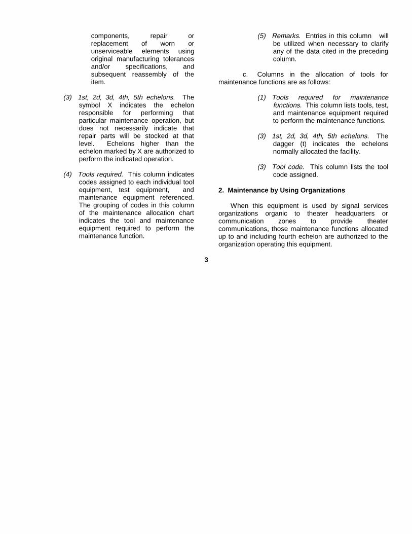
components, repair orreplacement of worn orunserviceable elements usingoriginal manufacturing tolerancesand/or specifications, andsubsequent reassembly of theitem.
(3) 1st, 2d, 3d, 4th, 5th echelons. Thesymbol X indicates the echelonresponsible for performing thatparticular maintenance operation, butdoes not necessarily indicate thatrepair parts will be stocked at thatlevel. Echelons higher than theechelon marked by X are authorized toperform the indicated operation.
(4) Tools required. This column indicatescodes assigned to each individual toolequipment, test equipment, andmaintenance equipment referenced.The grouping of codes in this columnof the maintenance allocation chartindicates the tool and maintenanceequipment required to perform themaintenance function.
(5) Remarks. Entries in this column willbe utilized when necessary to clarifyany of the data cited in the precedingcolumn.
c. Columns in the allocation of tools formaintenance functions are as follows:
(1) Tools required for maintenancefunctions. This column lists tools, test,and maintenance equipment requiredto perform the maintenance functions.
(3) 1st, 2d, 3d, 4th, 5th echelons. Thedagger (t) indicates the echelonsnormally allocated the facility.
(3) Tool code. This column lists the toolcode assigned.
2. Maintenance by Using Organizations
When this equipment is used by signal servicesorganizations organic to theater headquarters orcommunication zones to provide theatercommunications, those maintenance functions allocatedup to and including fourth echelon are authorized to theorganization operating this equipment.
3

SECTION II MAINTENANCE ALLOCATION CHART
ANALYZERS ZM-3/U; ZM-3A/U service Xinspect Xtest X 9, 3 Circuit Continuity-tubes etc.repair X 9 Easily replaced items
X 8adjust X 8calibrate X 1, 4 5, 6, 7overhaul X 1, 3, 4, 5, 6, 7
SELMS 004 TF ZM-3/U; AM-3A/U Army Ft Monmouth, NJ-MON 2135-631 Jun 63
PART OR COMPONENT MAINTENANCEFUNCTION
5THECH
1STECH
2NDECH
3RDECH REMARKS
TOOLSREQUIRED
4THECH
4

SECTION III ALLOCATION OF TOOLS FOR MAINTENANCE FUNCTIONS
1ST 2ND 3RD 4TH 5TH TOOLPART OR COMPONENT ECH ECH ECH ECH ECH CODE REMARKS
ANALYZERS ZM-3/U; ZM-3A/U
MULTIMETER TS-352 t t 1
TEST SET, ELECTRON TUBE TV-2 t 2
TEST SET, ELECTRON TUBE TV-7 t 3
METER TESTER TS-656 t t 4
METER TEST SET TS-682/GSM-1 t t 5
TEST SET, CAPACITANCE-IND-RES AN/URM-90 t t 6
CRYSTAL RECTIFIER TEST SET TS-268E t t 7
TOOL EQUIPMENT TK-21/G t t 8
TOOLS AND TEST EQUIPMENT ASSIGNED TO ORGANIZATIONAL REPAIRMAN t 9BY VIRTUE OF HIS ASSIGNED MISSION
SELMS 005 TF Army-Ft Monmouth, NJ-MON 2136-631Jun 63 ZM-3/U; ZM-3A/U
5
APPENDIX III (added)
BASIC ISSUE ITEMS LIST
Section I. INTRODUCTION
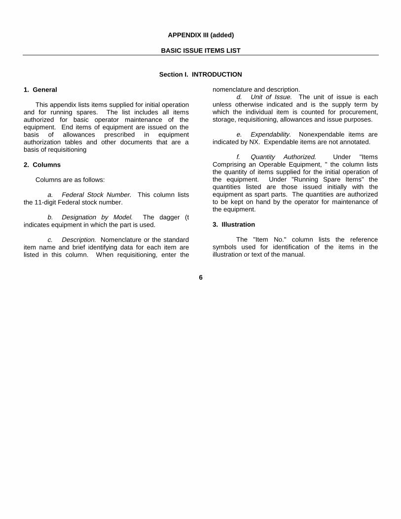
1. General
This appendix lists items supplied for initial operationand for running spares. The list includes all itemsauthorized for basic operator maintenance of theequipment. End items of equipment are issued on thebasis of allowances prescribed in equipmentauthorization tables and other documents that are abasis of requisitioning
2. Columns
Columns are as follows:
a. Federal Stock Number. This column liststhe 11-digit Federal stock number.
b. Designation by Model. The dagger (tindicates equipment in which the part is used.
c. Description. Nomenclature or the standarditem name and brief identifying data for each item arelisted in this column. When requisitioning, enter the
nomenclature and description.d. Unit of Issue. The unit of issue is each
unless otherwise indicated and is the supply term bywhich the individual item is counted for procurement,storage, requisitioning, allowances and issue purposes.
e. Expendability. Nonexpendable items areindicated by NX. Expendable items are not annotated.
f. Quantity Authorized. Under "ItemsComprising an Operable Equipment, " the column liststhe quantity of items supplied for the initial operation ofthe equipment. Under "Running Spare Items" thequantities listed are those issued initially with theequipment as spart parts. The quantities are authorizedto be kept on hand by the operator for maintenance ofthe equipment.
3. Illustration
The "Item No." column lists the referencesymbols used for identification of the items in theillustration or text of the manual.
6
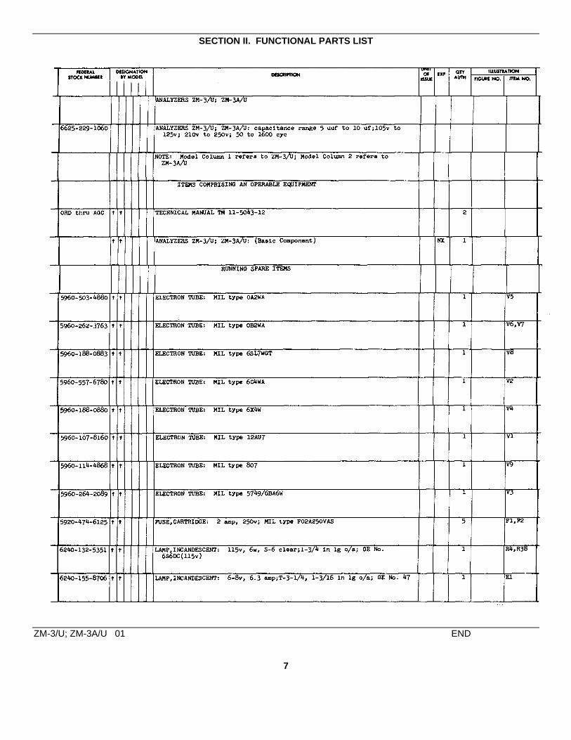
SECTION II. FUNCTIONAL PARTS LIST
ZM-3/U; ZM-3A/U 01 END
7

By Order of the Secretary of the Army:
HAROLD K. JOHNSONGeneral, United States Army,
Official: Chief of Staff.J. C. LAMBERT,Major General, United States Army,The Adjutant General.
Distribution:
Active Army:
USASA (2) GENDEP (0S) (1)CNGB (1) Sig Sec, GENDEP (4)CofT (1) Sig Dep (OS) (6)CofEngrs (1) Lexington Army Dep (6)TSG (1) Sacramento Army Dep (6)CC-E (2) Tobyhanna Army Dep (6)CofSptS (1) Letterkenny Army Dep (5)USACECDA (Ft Huachuca) (1) Ft Worth Army Dep (5)USACECDA (Ft Monmouth) (1) Sharpe Army Dep (3)USAARMBD (2) Navajo Army Dep (5)USAARTYBD (2) Charleston Army Dep (1)USCONARC (2) Savanna Army Dep (5)USAMC (2) Ft Huachuca (1)USAMICOM (2) WSMR (1)USAECOM (2) Sig Fld Maint Shops (1)USASMCOM (3) USA Elct R&D Lab (6)ARADCOM (2) USA Engr R&D Lab (2)ARADCOM Rgn (2) USA Cold Rgns RE Lab (2)OS Maj Comd (2) Chicago Proc Dist (1)OS Base Comd (2) Oakland Army Tml (5)USASCC (2) 1st USASA Fld Sta (1)Armies (1) Units org under fol TOE:USASCS (2) 11-587 (2)11th Air Assault Div (3) 11-592 (2)Svc Colleges (1) 11-597 (2)
NG: State AG (3) ; units-same as active Army except allowance is one (1) copy to each unit.
USAR: None.
For explanation of abbreviations used, see AR 320-50.
892-771
8

TM 11-5043-12C1
TECHNICAL MANUALOperator’s and Organizational Maintenance Manual
ANALYZERSZM-3/U AND ZM-3A/U
TM 11-5043-12 HEADQUARTERS,DEPARTMENT OF THE ARMY
CHANGES No. 1 WASHINGTON 25, D.C., 19 July 1963
TM 11-5043-12, 27 May 1958, is changed as follows:
Page 3. Make the following changes:
Delete paragraph 1f.
Delete paragraph 2 in its entirety and substitute:
2. Index of Publications
Refer to the latest issue of DA Pam 310-4 todetermine whether there are new editions, changes, oradditional publications pertaining to your equipment. DAPam 310-4 is an index of current technical manuals,technical bulletins, supply bulletins, lubrication orders,and modification work orders that are available throughpublications supply channels. The index lists theindividual parts (-10, -20, -35P, etc) and the latestchanges to and revisions of each equipment publication.
After paragraph 2, add paragraph 2.1.
2.1. Forms and Records
a. Reports of Maintenance and UnsatisfactoryEquipment. Use equipment forms and records inaccordance with instructions in TM 38-750
b. Report of Damaged or Improper Shipment.Fill out and forward DD Form 6 (Report of Damaged orImproper Shipment) as prescribed in AR 700-58 (Army),NAVSANDA Publication 378 (Navy), and AFR 71-4 (AirForce).
c. Comments on Manual. Forward allcomments on this publication direct to: CommandingOfficer, U.S. Army Electronics Materiel Support Agency,ATTN: SELMS-MP, Fort Monmouth, N.J. DA Form 1598(Record of Comments on Publications), DA Form 2496(Disposition Form), or letter may be used.
Page 16. Delete paragraphs 21 and 22 and substitute:
Section I. OPERATOR’S MAINTENANCE
21. Scope of MaintenanceThe maintenance duties assigned to the
operator of the analyzer are listed below together with areference to the paragraphs covering the specificmaintenance function. The duties assigned do notrequire tools or test equipment other than those issuedwith the analyzer.
a. Daily preventive maintenance checks andservices (par. 22.2).
b. Weekly preventive maintenance checksand services (par. 22.3).
c. Cleaning (par. 22.4).d. Troubleshooting (par. 23).e. Repairs and adjustments:
(1) Replacement of fuses (par. 24b).(2) Replacement of pilot lamp (par. 24c).(3) Replacement of lamp R4 or R38 (par.
24d).(4) Replacement of tubes (par. 24e).
22. Operator’s Preventive Maintenance
Preventive maintenance is the systematic care,servicing, and inspection of equipment to prevent theoccurrence of trouble, to reduce downtime, and to assurethat the equipment is serviceable.
a. Systematic Care. The procedures given inparagraphs 22.2 through 22.4 cover routine systematiccare and cleaning essential to proper upkeep andoperation of the equipment.
b. Preventive Maintenance Checks andServices. The preventive maintenance checks andservices charts (pars. 22.2 and 22.3) outline functions tobe performed at specific intervals. These checks andservices are to maintain Army electronic equipment in acombat serviceable condition; that is, in good general(physical) condition and in good operating condition. Toassist operators in maintaining combat
TAGO 5341-A - July
}
1

serviceability, the charts indicate what to check, how tocheck, and what the normal conditions are; thereferences column lists the illustrations, paragraphs, ormanuals that contain detailed repair or replacementprocedures. If the defect cannot be remedied by theoperator, higher echelon maintenance or repair isrequired. Records and reports of these checks andservices must be made in accordance with therequirements set forth in TM 38-750.
22.1. Preventive Maintenance Checks and ServicesPeriods
Preventive maintenance checks and services of theanalyzer are required daily. Paragraph 22.2 specifies theitems to be checked and serviced. In addition to theroutine daily checks and services, the equipment shouldbe rechecked and serviced immediately before going ona mission and as soon after completion of the mission aspossible.
22.2. Daily Preventive Maintenance Checks and Services Chart
Sequence Item Procedure References
1 Completeness -----------Check to see that the equipment is complete------------------------- TM 11-6625-241-12P.2 Cleanliness---------------Remove dirt and moisture from the surfaces, connectors, Paragraph 22.4.
cables and meter and dial windows.3 Meter-----------------------Inspect the meter for broken or cracked glass.4 Fuses ----------------------Check the fuses to see that they are properly seated and that Paragraph 24b.
they are not burned out. Replace if necessary.5 Lamp-----------------------Inspect the pilot lamp for proper seating. Check to see if the Paragraph 24c.
lamp filament is open. Replace if necessary.6 Knobs and switches----While operating the equipment, observe that the mechanical
action of each knob and switch is smooth and free frombinding.
7 Meter pointer-------------Check the meter pointer for erratic movement while operatingthe equipment.
8 Operation -----------------During operation, be alert for any unusual performance or Paragraph 23.condition.
22.3. Weekly Preventive Maintenance Checks and Services Chart
Sequence Item Procedure References
1 Power cable ----------- --Inspect power cable for breaks, deterioration, and loose con-nectors.
2 Exterior items--------- ---Inspect for Iooseness of accessible items such as clamps,hinges, panel hardware, and terminals. Tighten if necessary.
3 Exterior surfaces------ --Inspect exposed metal surfaces for rust, fungus, and corrosion.
22.4. CleaningInspect the exterior of the analyzer. The exterior
surfaces should be c(lean and free of dust, dirt, grease,and fungus.
a. Remove dust and loose dirt with a cleansoft cloth.
Warning: Cleaning compound is flammable andits fumes are toxic. Provide adequate ventilation.Do not use near a flame.
b. Remove grease, fungus, and ground-in dirtfrom the cases; use a cloth dampened (not wet) withcleaning compound.
c. Remove dust or dirt from plugs and jackswith a brush.
Caution: Do not press on the meter face (glass)when cleaning; the meter may be damaged.
d. Clean the front panels, meters, and controlknobs; use a soft clean cloth. If dirt is difficult to remove,dampen the cloth with water; mild soap may be used formore effective cleaning.
TAGO 5341-A
2

Section II. ORGANIZATIONAL MAINTENANCE
22.5. Organizational Preventive Maintenancea. Organizational preventive maintenance is
the systematic care, inspection, and servicing ofequipment to maintain it in serviceable condition, preventbreakdowns, and assure maximum operationalcapability. Preventive maintenance is the responsibilityof all echelons concerned with the equipment andincludes the inspection, testing, and repair orreplacement of parts, subassemblies, or units thatinspection and tests indicate would probably fail beforethe next scheduled periodic service. Preventivemaintenance checks and services of the analyzer at thesecond echelon level are made at monthly intervalsunless otherwise directed by the commanding officer.
b. Maintenance forms and records to be usedand maintained on this equipment ale specified in TM38-750.
22.6. Monthly MaintenancePerform the maintenance functions indicated in the
monthly preventive maintenance checks and serviceschart (par. 22.7) once each month. A month is definedas approximately 30 calendar days of 8-hour-per-dayoperation. If the equipment is operated 16 hours a day,the monthly preventive maintenance checks andservices should be performed at 15-day intervals.Adjustment of the maintenance interval must be madeto compensate for any unusual operating conditions.Equipment maintained in a standby (ready for immediateoperation) condition must have monthly preventivemaintenance checks and services performed on it.Equipment in limited storage (requires service beforeoperation) does not require monthly preventivemaintenance.
22.7. Monthly Preventive Maintenance Checks and Services Chart
Sequence Item Procedure References
1 Completeness -----------See that the equipment is complete (TM 11-6625-241-12P).2 Installation ---------------See that the equipment is properly installed (pars. 11a and b).3 Cleanliness --------------See that the equipment is clean (par. 22.4).4 Preservation -------------Check all surfaces for evidence of fungus. Remove rust and Paragraph 22.8.
corrosion and spot-paint bare spots.5 Publications --------------See that all publications are complete, serviceable, and current DA Pam 310-4.6 Modifications-------------Check DA Pam 310-4 to determine if new applicable MWO’s DA Pam 310-4.
have been published. All URGENT MWO’s must beapplied immediately. All ROUTINE MWO’s must bescheduled.
7 Pluckout items-----------Inspect clamps and seating of pluckout items. Check for Figures 9 and 10.wrong, bent, or broken parts.
8 Resistors and ------------Inspect resistors for cracks and blistering and capacitors forcapacitors broken or cracked insulation.
9 Rotary switches ---------Inspect rotary switches for broken wires and insulators.10 Screw-type terminals --Check to see that all screw-type terminals area secure. Tighten
as necessary (fig. 4).11 Meter-----------------------Inspect the meter for broken or cracked glass.12 Fuses ---------------------Check the fuses to see that they are properly seated and that Paragraph 24b.
they are in operating condition. Replace if necessary.13 Lamps ---------------------Inspect the pilot lamp (fig. 4) and filter lamp R38 or R4 (fig. Paragraphs 24c
10) for open filaments. Replace if necessary. and d.14 Knobs and switches----While making the operating checks, observe that the mechani-
cal action of each knob and switch is smooth and free frombinding.
15 Meter pointer-------------Check the meter pointer for erratic movement when operatingthe equipment.
16 Operating check --------Refer to paragraph 23.17 Spare parts---------------Check all spare parts for general condition and method of TM 11-6625-241-
storage. There should be no evidence of overstock, and all 12P.shortages must be on valid requisitions.
TAGO 5341-A
3

22.8. Cleaning and Touchup Painting Instructions
Clean rust and corrosion from metal surfaces bylightly sanding them with fine sandpaper. Brush two thincoats of paint on the bare metal to protect if from furthercorrosion. Refer to the applicable cleaning andrefinishing practices specified in TM 9-213.
Page 17. Delete figure 7.Page 18. Delete figure 8.Page 23, appendix I. Add the following:
DA Pam 310-4 Index of Technical Manuals,Technical Bulletins, SupplyBulletins, LubricationOrders, and Modification
Work Orders.
TM 9-213 Painting Instructions forField Use.
TM 11-6625-241-12P Operator’s andOrganizationalMaintenance Repair Partsand Special Tools Lists forAnalyzers ZM-3/U andZM-3A/U.
TM 38-750 The Army EquipmentRecord System andProcedures.
TAGO 5341-A
4

By Order of the Secretary of the Army:EARLE G. WHEELER,General, United States Army,
Official: Chief of Staff.J. C. LAMBERT,Major General, United States Army,The Adjutant General.
Distribution:Active Army:
DASA (6) USA Trans Tml Comd (1) 11-156USASA (2) Army Tml (1) 11-157CNGB (1) POE (1) 11-158Cof Engrs (1) USAOSA (1) 11-165TSG (1) AMS (1) 11-167CSigO (7) WRAMC (1) 11-500 (AA-AC, RM-RU)CofT (1) AFIP (1) 11-555C/Spt Svcs (1) Army Pic Cen (2) 11-557USA CD Agcy (1) USA Mbl Spt Cen (1) 11-587USCONARC (5) USA Elct Mat Agcy (12) 11-592USAMC (5) Chicago Proc Dist (1) 11-597ARADCOM (2) USARCARIB Sig Agcy (1) 11-608ARADCOM Rgn (2) Sig Fld Maint Shop (3) 17OS Maj Comd (3) USA Corps (3) 29-1OS Base Comd (2) Units organized under following 29-21LOGCOMD (2) TOE’s: 29-25USAECOM (5) Two copies each unit: 29-26USAMICOM (3) 5-600 29-27USASCC (4) 5-605 29-35MDW (1) 7 29-36Armies (2) 7-52 29-37Corps (2) 7-100 29-56USATC AD (2) 9-47 32-56USATC Engr (2) 9-87 32-67USATC Inf (2) 9-227 37USATC Armor (2) 9-377 37-100Instl (2) except 9-500 (AA-AC) 44-435Ft Monmouth (63) 11-5 44-437Svc College (2) 11-6 44-445Br Svc Sch (2) 11-7 44-446GENDEP (OS) (2) 11-15 44-447Sig Dep (OS) (12) 11-16 44-448Sig Sec, GENDEP (OS) (5) 11-36 44-535Army Dep (2) except 11-38 44-536Ft Worth (8) 11-55 44-537Lexington (12) 11-56 44-544Sacramento (28) 11-57 44-545Tobyhanna (12) 11-68 44-546Frankford Arsenal (5) 11-96 44-547USA Elct RD Actv, White Sands 11-97 44-548(13) 11-98 57USA Elct RD Actv, Ft Huachuca 11-117 57-100(2) 11-155
NG: State AG (3); units-same as active Army except allowance is one copy each unit.USAR: None.For explanation of abbreviations used, see AR 320-50.
TAGO 5341-A5
TM 11-5043-12
TECHNICAL MANUAL HEADQUARTERS,DEPARTMENT OF THE ARMY
No. 11-5043-12 WASHINGTON 25, D. C., 27 May 1958.
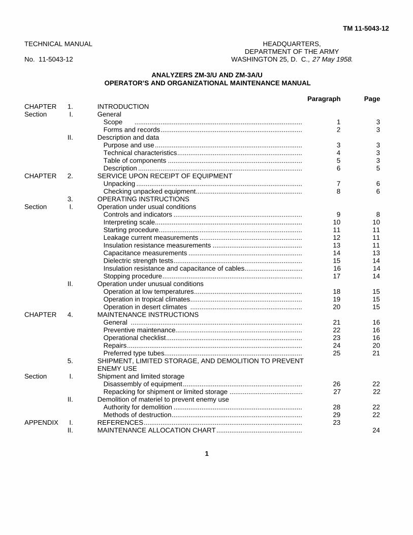
ANALYZERS ZM-3/U AND ZM-3A/UOPERATOR’S AND ORGANIZATIONAL MAINTENANCE MANUAL
Paragraph PageCHAPTER 1. INTRODUCTIONSection I. General
Scope .......................................................................................... 1 3Forms and records............................................................................ 2 3
II. Description and dataPurpose and use............................................................................... 3 3Technical characteristics................................................................... 4 3Table of components ........................................................................ 5 3Description ........................................................................................ 6 5
CHAPTER 2. SERVICE UPON RECEIPT OF EQUIPMENTUnpacking ......................................................................................... 7 6Checking unpacked equipment......................................................... 8 6
3. OPERATING INSTRUCTIONSSection I. Operation under usual conditions
Controls and indicators ..................................................................... 9 8Interpreting scale............................................................................... 10 10Starting procedure............................................................................. 11 11Leakage current measurements ....................................................... 12 11Insulation resistance measurements ................................................ 13 11Capacitance measurements ............................................................. 14 13Dielectric strength tests..................................................................... 15 14Insulation resistance and capacitance of cables............................... 16 14Stopping procedure........................................................................... 17 14
II. Operation under unusual conditionsOperation at low temperatures.......................................................... 18 15Operation in tropical climates............................................................ 19 15Operation in desert climates ............................................................ 20 15
CHAPTER 4. MAINTENANCE INSTRUCTIONSGeneral ............................................................................................ 21 16Preventive maintenance.................................................................... 22 16Operational checklist......................................................................... 23 16Repairs.............................................................................................. 24 20Preferred type tubes.......................................................................... 25 21
5. SHIPMENT, LIMITED STORAGE, AND DEMOLITION TO PREVENTENEMY USE
Section I. Shipment and limited storageDisassembly of equipment................................................................ 26 22Repacking for shipment or limited storage ....................................... 27 22
II. Demolition of materiel to prevent enemy useAuthority for demolition ..................................................................... 28 22Methods of destruction...................................................................... 29 22
APPENDIX I. REFERENCES..................................................................................... 23II. MAINTENANCE ALLOCATION CHART.............................................. 24
1

Figure 1. Analyzer ZM-3A/U, less running spares.
2
CHAPTER 1
INTRODUCTION
Section I. GENERAL
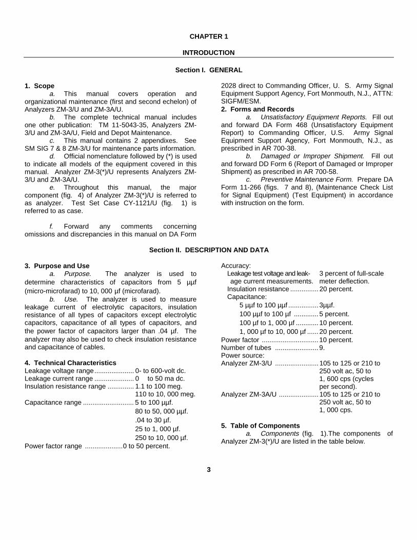
1. Scopea. This manual covers operation and
organizational maintenance (first and second echelon) ofAnalyzers ZM-3/U and ZM-3A/U.
b. The complete technical manual includesone other publication: TM 11-5043-35, Analyzers ZM-3/U and ZM-3A/U, Field and Depot Maintenance.
c. This manual contains 2 appendixes. SeeSM SIG 7 & 8 ZM-3/U for maintenance parts information.
d. Official nomenclature followed by (*) is usedto indicate all models of the equipment covered in thismanual. Analyzer ZM-3(*)/U represents Analyzers ZM-3/U and ZM-3A/U.
e. Throughout this manual, the majorcomponent (fig. 4) of Analyzer ZM-3(*)/U is referred toas analyzer. Test Set Case CY-1121/U (fig. 1) isreferred to as case.
f. Forward any comments concerningomissions and discrepancies in this manual on DA Form
2028 direct to Commanding Officer, U. S. Army SignalEquipment Support Agency, Fort Monmouth, N.J., ATTN:SIGFM/ESM.2. Forms and Records
a. Unsatisfactory Equipment Reports. Fill outand forward DA Form 468 (Unsatisfactory EquipmentReport) to Commanding Officer, U.S. Army SignalEquipment Support Agency, Fort Monmouth, N.J., asprescribed in AR 700-38.
b. Damaged or Improper Shipment. Fill outand forward DD Form 6 (Report of Damaged or ImproperShipment) as prescribed in AR 700-58.
c. Preventive Maintenance Form. Prepare DAForm 11-266 (figs. 7 and 8), (Maintenance Check Listfor Signal Equipment) (Test Equipment) in accordancewith instruction on the form.
Section II. DESCRIPTION AND DATA
3. Purpose and Usea. Purpose. The analyzer is used to
determine characteristics of capacitors from 5 µµf(micro-microfarad) to 10, 000 µf (microfarad).
b. Use. The analyzer is used to measureleakage current of electrolytic capacitors, insulationresistance of all types of capacitors except electrolyticcapacitors, capacitance of all types of capacitors, andthe power factor of capacitors larger than .04 µf. Theanalyzer may also be used to check insulation resistanceand capacitance of cables.
4. Technical CharacteristicsLeakage voltage range..................... 0- to 600-volt dc.Leakage current range ..................... 0 to 50 ma dc.Insulation resistance range .............. 1.1 to 100 meg.
110 to 10, 000 meg.Capacitance range ........................... 5 to 100 µµf.
80 to 50, 000 µµf..04 to 30 µf.25 to 1, 000 µf.250 to 10, 000 µf.
Power factor range ....................0 to 50 percent.
Accuracy:Leakage test voltage and leak- 3 percent of full-scaleage current measurements. meter deflection.
Insulation resistance ............... 20 percent.Capacitance:
5 µµf to 100 µµf ................ 3µµf.100 µµf to 100 µf ............. 5 percent.100 µf to 1, 000 µf ............ 10 percent.1, 000 µf to 10, 000 µf ...... 20 percent.
Power factor .............................. 10 percent.Number of tubes ....................... 9.Power source:Analyzer ZM-3/U ....................... 105 to 125 or 210 to
250 volt ac, 50 to1, 600 cps (cyclesper second).
Analyzer ZM-3A/U ..................... 105 to 125 or 210 to250 volt ac, 50 to1, 000 cps.
5. Table of Componentsa. Components (fig. 1).The components of
Analyzer ZM-3(*)/U are listed in the table below.
3

Quan- Height Depth Width Unittity Item (in.) (in.) (in.) weight
(lb.)1 Analyzer (for
ZM-3/U) 10 3/8 8 5/8 13 7/8 34 3/4or
Analyzer (forZM-3A/U) 10 1/4 9 1/4 13 1/2 27 1/4
1 Test SetCase CY-1121/U (forZM-3/U) 14 3/8 12 1/2 17 5/8 15 1/4
orTest SetCase CY-1121/U (forZM-3A/U) 13 7/8 11 1/2 17 1/2 18 3/4
1 set Running spares (b
below)
b. Running Spares (fig. 2)
Quan- Item Quan- Itemtity tity
5 Fuses, 2-ampere 1 Electron tube, 8071 Electron tube, OA2 1 Electron tube,1 Electron tube, OB2 5749/6BA6W1 Electron tube, 6C4W 1 Incandescent lamp,1 Electron tube, #47
6SL7WGT 1 Incandescent lamp:1 Electron tube, 110 v, 6w
6X4W (ZM-3/U)1 Electron tube, 115 v, 6w
12AU7 (ZM-3A/U)
Figure 2. Running spares.
4

6. Description(fig. 1)
The analyzer is a self-contained instrument which ishoused in a dust cover. In transit, the analyzer isinstalled in a shock-mounted case. All operating controls(except the change-over switch) and terminals arelocated on the front panel. The change-over switch islocated behind a plate on the rear of the dust cover. The
operating controls and terminals are located in threecolored sections on the front panel as follows:
a. Maroon. Controls and terminals for leakagecurrent measurements.
b. Gray. Controls and terminals for insulationresistance measurements.
c. Green. Controls and terminals forcapacitance measurements.
5

CHAPTER 2
SERVICE UPON RECEIPT OF EQUIPMENT
7. Unpacking(fig. 3)a. Packaging Data. Analyzer ZM-3(*)/U is
packed for shipment in a wooden packing case. Thedimensions of the packed equipment are 22 by 17 by 14inches; the weight is 60 pounds, and the volume is 3cubic feet.
b. Unpacking.(1) Cut and fold back the metal straps.(2) Remove the nails from the wooden
cover with a nail puller. Do notattempt to pry off the wooden cover;prying may damage the equipment.Remove the wooden cover andexpose the moistureproof barrier.
(3) Slit the moistureproof barrier andexpose the outer corrugated carton.
(4) Open the outer corrugated carton bycutting the gummed tape and exposethe moisture-vaporproof barrier.
(5) Slit the moisture-vaporproof barrierand expose the inner corrugatedcarton.
(6) Open the inner corrugated carton bycutting the gummed tape and removethe contents.
(7) Remove the cover from the case andremove the running spares from insidethe case.
8. Checking Unpacked Equipment
a. Inspect the equipment for any loss ordamage that might have occurred during shipment. Ifthe equipment has been damaged or is incomplete,refer to paragraph 2.
b. Check the equipment against the packinglist. When no packing list accompanies the equipment,use the table of components (par. 5) as a general checkto indicate the equipment which probably was packed.
6

Figure 3. Packaging diagram.
7

CHAPTER 3
OPERATING INSTRUCTIONS
Section I. OPERATION UNDER USUAL CONDITIONS
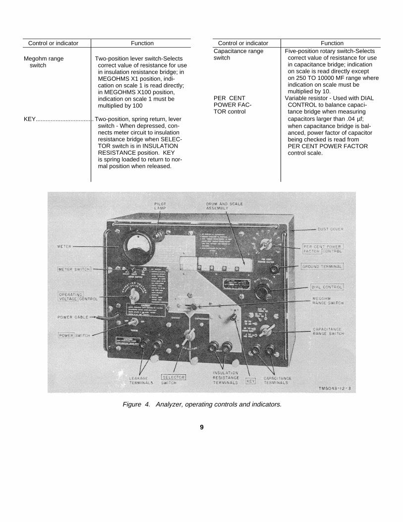
9. Controls and Indicators(fig. 4)
The operating controls and indicators and their functionsare listed in the table below.
Control or indicator Function
Changeover switch Toggle switch, single-pole double-(behind rear throw-Permits operation onplate). 110- or 220-volt ac.
POWER switch- ................ Toggle switch, double-pole, double-throw-In ON position, appliespower to analyzer; in OFF posi-tion, applies power to internalheater.
SELECTOR switch. Three-position rotary switch-
Position FunctionLEAKAGE Connects meter
circuit andleakage ter-minals tohigh-voltagerectifier tomeasure leak-age current ofelectrolyticcapacitors.
INSULATION Connects insu-RESISTANCE lation resist-
ance bridgeto meter cir-cuit to meas-ure insulationresistance ofcapacitors.
CAPITANCE Connects capac-itance bridgeto meter cir-cuit to meas-ure capaci-tance.
Pilot lamp .......................... Indicator lamp assembly-Indi-cates POWER switch is in ONposition.
Control or indicator Function
METER SWITCH Three-position spring return, leverswitch-
Position Function600 VOLTS Connects meter and(normal meter multiplierposition) to high-voltage
rectifier to meas-ure leakage testvoltage.
60 VOLTS Connects meter and(spring meter multiplierreturn) to high-voltage
rectifier to meas-ure leakage testvoltage.
50 MA. Connects meter to(spring leakage terminalsreturn) to measure leak-
age current ofelectrolytic capac-itors.
Meter ............................... Dc voltmeter and dc milliammeter.Indicates leakage test voltage,leakage current of electrolyticcapacitors, and balance of insula-tion resistance bridge or capaci-tance bridge.
OPERATING Variable resistor-Controls leakageVOLTAGE test voltage.
control.DIAL CONTROL ............... Drum and scale assembly-Oper-
ates drum and scale assemblywhich is connected to variableresistor used to balance insula-tion resistance bridge or capaci-tance bridge on scales 3, 4, and 5; connected to variable
capa citorused to balance capacitancebridge on scale 2. Value of in-sulation resistance or capacitanceis indicated on scale.
8
Control or indicator Function
Megohm range Two-position lever switch-Selectsswitch correct value of resistance for use
in insulation resistance bridge; inMEGOHMS X1 position, indi-cation on scale 1 is read directly;in MEGOHMS X100 position,indication on scale 1 must bemultiplied by 100
KEY................................... Two-position, spring return, leverswitch - When depressed, con- nects meter circuit to insulationresistance bridge when SELEC-TOR switch is in INSULATIONRESISTANCE position. KEYis spring loaded to return to nor-mal position when released.
Control or indicator FunctionCapacitance range Five-position rotary switch-Selectsswitch correct value of resistance for use
in capacitance bridge; indicationon scale is read directly excepton 250 TO 10000 MF range whereindication on scale must bemultiplied by 10.
PER CENT Variable resistor - Used with DIALPOWER FAC- CONTROL to balance capaci-TOR control tance bridge when measuring
capacitors larger than .04 µf;when capacitance bridge is bal-anced, power factor of capacitorbeing checked is read fromPER CENT POWER FACTORcontrol scale.
Figure 4. Analyzer, operating controls and indicators.
9
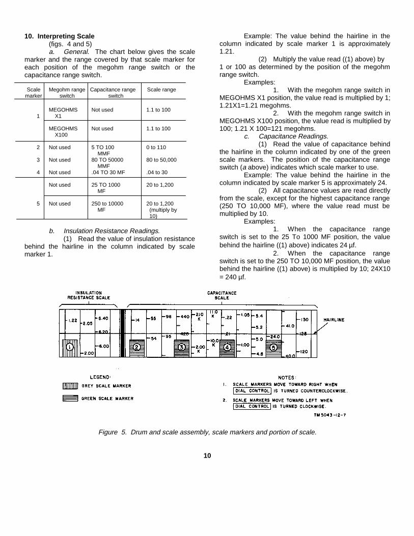
10. Interpreting Scale(figs. 4 and 5)a. General. The chart below gives the scale
marker and the range covered by that scale marker foreach position of the megohm range switch or thecapacitance range switch.
Scale Megohm range Capacitance range Scale rangemarker switch switch
MEGOHMS Not used 1.1 to 1001 X1
MEGOHMS Not used 1.1 to 100X100
2 Not used 5 TO 100 0 to 110MMF
3 Not used 80 TO 50000 80 to 50,000MMF
4 Not used .04 TO 30 MF .04 to 30
Not used 25 TO 1000 20 to 1,200MF
5 Not used 250 to 10000 20 to 1,200MF (multiply by
10)
b. Insulation Resistance Readings.(1) Read the value of insulation resistance
behind the hairline in the column indicated by scalemarker 1.
Example: The value behind the hairline in thecolumn indicated by scale marker 1 is approximately1.21.
(2) Multiply the value read ((1) above) by1 or 100 as determined by the position of the megohmrange switch.
Examples:1. With the megohm range switch in
MEGOHMS X1 position, the value read is multiplied by 1;1.21X1=1.21 megohms.
2. With the megohm range switch inMEGOHMS X100 position, the value read is multiplied by100; 1.21 X 100=121 megohms.
c. Capacitance Readings.(1) Read the value of capacitance behind
the hairline in the column indicated by one of the greenscale markers. The position of the capacitance rangeswitch (a above) indicates which scale marker to use.
Example: The value behind the hairline in thecolumn indicated by scale marker 5 is approximately 24.
(2) All capacitance values are read directlyfrom the scale, except for the highest capacitance range(250 TO 10,000 MF), where the value read must bemultiplied by 10.
Examples:1. When the capacitance range
switch is set to the 25 To 1000 MF position, the valuebehind the hairline ((1) above) indicates 24 µf.
2. When the capacitance rangeswitch is set to the 250 TO 10,000 MF position, the valuebehind the hairline ((1) above) is multiplied by 10; 24X10= 240 µf.
Figure 5. Drum and scale assembly, scale markers and portion of scale.
10

11. Starting Procedure(fig. 4)a. Check the position of the changeover
switch (not shown) to be sure that is is set properly forthe available power source.
b. Connect the power cable to the powersource (par. 4).
c. Operate the POWER switch to the ONposition. Allow the analyzer to warm up for 2 minutesbefore proceeding.
12. Leakage Current Measurements(fig. 4)
To measure the leakage current of electrolyticcapacitors, proceed as follows:
a. Perform the starting procedures (par. 11).b. Set the SELECTOR switch to the
LEAKAGE position.c. Locate the working voltage on the capacitor
to be tested.d. Adjust the OPERATING VOLTAGE control
until the meter indicates the correct working voltage (cabove). If the voltage is less than 60 volts, use the 60VOLTS position of the METER SWITCH.
e. Observing polarity, connect the capacitor tothe leakage terminals.
f. Hold the METER SWITCH in the 50 MA.position.
(1) If the meter needle goes off scale,release the METER SWITCH. Thecapacitor is shorted.
(2) A leakage current indication of 5milliamperes (ma) or less indicates thatthe capacitor is acceptable. Discardcapacitors that have a leakage currenthigher than 5 ma.
Warning: Do not touch the capacitorleads or the leakage terminals; up to600 volts direct current (dc) is appliedto the leakage terminals when theMETER SWITCH is in the 50 MA.position.
g. Release the METER SWITCH.h. Turn the OPERATING VOLTAGE control
counterclockwise to its stop.i. Remove the capacitor from the leakage
terminals.
13. Insulation Resistance Measurementsa. Insulation Resistance Values. The
minimum insulation resistance values are given in (1)through (4) below. Discard capacitors which haveinsulation resistance values lower than the values given.
(1) Fixed ceramic and air dielectric types.The insulation resistance of fixedcompensating and high K ceramic
capacitors and air dielectric capacitorsshould be higher than 1,000 megohms.
(2) Variable ceramic and micacapacitors. The insulation resistance ofvariable ceramic and mica capacitorsshould be higher than 3,000 megohms.
(3) Paper capacitors (oil impregnated).(a) The insulation resistance of oil
impregnated paper capacitorsshould equal or exceed the valuesindicated in the chart below. Thecharacteristic letter is the thirdletter from the right in the typedesignation on the capacitor.
Insulation resistance (meg x µf)Characteristic
letter 20° C. 25° C. 40° C. 85° C.
A ------------------ 2,840 2,000 700 20B ------------------ 2,130 1,500 525 15D ------------------ 710 500 175 5E ------------------ 2,840 2,000 700 20F ------------------ 2,130 1,500 525 15K ------------------ 5,680 4,000 1,400 10(125° C.)
Note. Normal room temperature is approximately 25° C.
(b) The insulation resistance given inthe chart ((a) above) is the productof the insulation resistance inmegohms and the capacitance inµf. To determine the minimumacceptable insulation resistance ofa given capacitor, proceed asfollows: 1. Take the insulationresistance value from the chart atthe temperature of the capacitor.2. Divide this figure by the
capacitance value in µf.3. The result is the minimum
value of insulation resistancein megohms.
Example: A 4-µfcapacitor (characteristic letterK) at 25° C. has aninsulation resistance of4,000; therefore, 4,000divided by 4 equals 1,000megohms.
(4) Paper capacitors (wax impregnated).The insulation resistance of wax impregnated
11

CAPACITOR COLOR CODE MARKING(MIL-STD CAPACITORS)
Figure 6. MIL-STD capacitor color-code marking.
CAPACITOR COLOR CODE
12

paper capacitors should be measuredonly at temperatures between -10° and+55° C. They should be within thelimits specified for characteristic letter B((3) (a) above).
b. Procedure (fig. 4).(1) Perform the starting procedures (par.
11).(2) Set the SELECTOR switch to the
INSULATION RESISTANCE position.The meter will indicate 10 ma.
(3) If the insulation resistance of ceramic,air, or mica capacitors is to bemeasured, place the megohm rangeswitch on the MEGOHMS X100position; for paper capacitors, set themegohm range switch to MEGOHMSX1 for readings between 1.1 and 100megohms and to MEGOHMS X100 forreadings between 110 and 10,000megohms.
(4) When testing ceramic or air dielectriccapacitors, adjust the DIAL CONTROLfor a reading of 10 on scale 1 (par.10b); for mica capacitors, adjust theDIAL CONTROL for a scale reading of30. When testing paper capacitors,adjust the DIAL CONTROL until thescale reading times the number (1 or100) indicated by the position of themegohm range switch equals theresistance value (a(3) and (4) above).
(5) Connect the capacitor to the insulationresistance terminals. Allow 2 minutesfor the capacitor to charge beforeproceeding.
Warning: Do not touch the insulationresistance terminals or the leads of thecapacitor when connecting thecapacitor; 105 volts dc is applied to theinsulation resistance terminals.
(6) Depress the KEY and watch the meter.If the needle deflects to the right, thecapacitor is acceptable.
Caution: If the meter needle goes offscale to the left, release the KEY. Thecapacitor is shorted. The meter maybe damaged if the KEY is held in theclosed position too long.
(7) Adjust the DIAL CONTROL until themeter indicates 10 ma.
(8) Read the insulation resistance behindthe harline in the column indicated bythe position of scale marker 1 (par.10b).
(9) Release the KEY.
(10) Remove the capacitor from theinsulation resistance terminals.
Warning: Discharge the capacitorby shorting the capacitor leads after theleads have been removed from theinsulation resistance terminals. Whiletesting, the capacitor is charged to 105volts dc.
14. Capacitance Measurementsa. Tolerances. There are six types of
capacitors, each having a different tolerance.Tolerances for each type are as follows:
(1) Temperature compensating ceramictypes and mica types. The capacitanceof fixed and variable temperaturecompensating ceramic and fixed micacapacitors should be within the limitsindicated by the letter in the typedesignation or by the color code at anytemperature between -40° and +55° C.
(2) High K and special purpose ceramictypes. The capacitance should bewithin the limits marked on thecapacitor at any temperaturebetween -40° and +55° C.
Note. The high K ceramiccapacitors are very unstable. Difficultyin balancing the bridge does notnecessarily indicate a defectivecapacitor.
(3) Paper capacitors (oil-impregnated).The capacitance of oil-impregnatedpaper capacitors should be within thelimits indicated by the letter in the typedesignation or within ± 20 percent whenthe tolerance is not indicated at anytemperature between 0° and +55°C.Oil-impregnated paper capacitorsmeasured between -40° and 0° C.would not show an open or short circuit.The measurement of capacitance atthese low temperatures is notsignificant.
(4) Paper capacitors (wax-impregnated).The capacitance of wax-impregnatedpaper capacitors should be within thelimits indicated by the letter in the typedesignation or within ± 20 percent whenthe tolerance is not indicated;measurements should be made attemperatures between -10° and +55°C.
(5) Electrolytic capacitors. Thecapacitance of electrolytic capacitorsshould be not less than 90 percent normore than 150 percent of the ratedvalue at temperatures between +25°and +55° C.
13

(6) Air dielectric capacitors. Tuning andtrimmer capacitors should have maximum and minimumcapacitances within the limits required by theirapplication.
b. Procedure (fig. 4).(1) Perform the starting procedures (par.
11).(2) Set the SELECTOR switch to the
CAPACITANCE position.(3) Set the capacitance range switch to the
range which includes the approximatevalue of the capacitor to be measured.
(4) Set the DIAL CONTROL so that theapproximate value of the capacitor tobe measured is indicated behind thehairline (par. 10c).
(5) Connect the capacitor to thecapacitance terminals. The meterindication will probably be off scale tothe right.
(6) Adjust the DIAL CONTROL for aminimum indication on the meter. Forcapacitors larger than 4 µf, adjust boththe DIAL CONTROL and thePERCENT POWER FACTOR controlfor a minimum indication on the mater.(a) If the minimum meter indication
occurs more than 10 percentbelow the lower capacitortolerance the capacitor is open.
(b) If a minimum meter indication cannot be obtained, the capacitor isshorted.
(c) If the meter indication is notsteady, the capacitor is probablyintermittent. Tapping the case orstriking it lightly against a table willsometimes show up anintermittent capacitor.
(7) Read the capacitance value on theproper scale (par. 10c) as indicated bythe position of the capacitance rangeswitch.
(8) The power factor of capacitors largerthan 4 of will be indicated by theposition of the PERCENT POWERFACTOR control.
Note. For electrolytic capacitorsrated under 100 volts, 50 percent is themaximum power factor acceptable: forelectrolytic capacitors rated at 100 voltsor higher, 15 percent is the maximumpower factor acceptable.
(9) Remove the capacitor from thecapacitance terminals.
15. Dielectric Strength Testsa. Requirements.
(1) Fixed and variable temperaturecompensated ceramic capacitorsshould withstand 600 volts dc for 1minute with no current indicated on themeter.
(2) High K ceramic capacitors shouldwithstand 300 volts dc for 1 minute withno current indicated on the meter.
b. Procedure (fig. 4).(1) Perform the starting procedures (par.
11).(2) Set the SELECTOR switch to the
LEAKAGE position.(3) Adjust the OPERATING VOLTAGE
control until the meter indicates 600volts or 300 volts as required (a above).
(4) Connect the capacitor to the leakageterminals.
(5) Hold the METER SWITCH in the 50MA. position for 1 minute.
Warning: Do not touch thecapacitor leads or the leakageterminals; up to 600 volts dc is appliedto the leakage terminals when theMETER SWITCH is in the 50 MA.position.(a) If the needle goes off scale,
release the METER SWITCH; thecapacitor is shorted.
(b) If no current is indicated, thecapacitor is acceptable.
(6) Release the METER SWITCH.(7) Turn the OPERATING VOLTAGE
control counterclockwise to its stop.(8) Remove the capacitor from the leakage
terminals.
16. Insulation Resistance and Capacitance of Cablesa. To measure the insulation resistance of
cables, follow the procedures in paragraph 13.b. To measure the capacitance of cables,
follow the procedures in paragraph 14.
17. Stopping Procedure(fig. 4)a. To return the analyzer to a standby
condition, set the POWER switch to the OFF position.b. To shut down the analyzer completely, set
the POWER switch to the OFF position, and remove thepower cable from the power source.
14
Section II. OPERATION UNDER UNUSUAL CONDITIONS
18. Operation at Low TemperaturesLow temperatures affect the efficient operation of the
analyzer. Instructions and precautions for operationunder these conditions are as follows:
a. Keep the equipment warm and dry. A built-in heater resistor keeps the analyzer warm, therebyminimizing moisture condensation. The heater resistoris on when the POWER switch is in the OFF position.Always keep the power cable connected to the powersource and the POWER switch in the OFF position whenthe equipment is not being used. This will also eliminateexcessively long warm-up periods when the equipment isnot used frequently.
b. If equipment has been exposed to the coldand is brought into a warm room, moisture will gather onthe equipment until it reaches room temperature. Whenthe equipment has reached room temperature, dry itthoroughly. This condition also arises when equipmentwarms up during the day after exposure during a coldnight.
19. Operation in Tropical ClimatesMoisture conditions are more acute in tropical,
swampy areas. The high relative humidity causesmoisture on the equipment. Adequate ventilation will
minimize this condition. Dry the equipment thoroughlybefore operating it. Keep the power cable connected tothe power source and the POWER switch in the OFFposition. The built-in heater resistor will help keep theanalyzer dry.
20. Operation in Desert Climatesa. Conditions similar to those encountered in
tropical climates often prevail in desert areas. Use thesame measures as for tropical climates (par. 19) toinsure proper operation of the equipment. A commoncondition in desert areas is high temperature during theday and a large drop in temperature during the night.This leads to condensation of moisture.
b. Provide means for keeping dust and sandfrom entering the moving parts of the equipment. Grit,resulting from the mixture of lubricant and sand, willdamage the equipment. Clean and lubricate theequipment more often; cover the equipment when not inuse. If possible, protect the equipment from the directrays of the sun.
15

CHAPTER 4
MAINTENANCE INSTRUCTIONS
21. GeneralThe procedures outlined in this chapter are to be
performed by the operator and organizationalmaintenance personnel. Organizational maintenance ofthe analyzer is limited to preventive maintenance. Nospecial tools or test equipment is required.
22. Preventive Maintenance(figs. 7 and 8)
DA Form 11-266 is a preventive maintenancechecklist to be used by the operator and organizationalmaintenance personnel. Items not applicable to theequipment are lined out on the form. References in theITEM block are to paragraphs that contain additional
maintenance information pertinent to the particular item.Instructions for use of the form appear on page 1 of theform.
23. Operational Checklista. General. The operational checklist (b
below) provides a procedure for systematically checkingequipment performance. All corrective measures thatthe operator or second-echelon repairman can performare given in the corrective measures column. If thecorrective measures indicated do not restore normalequipment performance, repair is required by higherechelon maintenance personnel. Note on the repair taghow the equipment performed and the correctivemeasures that were taken.
16

Figure 7. DA Form 11-266, pages 1 and 4.
17

Figure 8. DA Form 11-266, pages 2 and 3.
18

b. Check list
Item Action Normal indication Corrective measures
1 Check position of changeover switch tobe sure that it is set for proper inputvoltage.
2 Connect power cable to power source.3 Operate POWER switch to ON. Allow Pilot lamp lights...................................Replace pilot lamp E1 (par. 24c)
2 minutes for warm up before pro- Replace fuse F1 or F2 (par. 24b)ceeding. Check connection of power cable
4 Turn OPERATING VOLTAGE con-trol to its extreme counterclockwiseposition.
5 Operate SELECTOR switch to LEAK-AGE position.
6 Hold METER SWITCH in 60 VOLTS Meter indicates from 4 to 10 volts .......Replace lamp R38 (par. 24d)position Replace tube V9 (par. 24e)
7 Release meter switch........................................ METER SWITCH returns to 600 .........Higher-echelon repair requiredVOLTS position.
8 Turn OPERATING VOLTAGE con- Meter reading increases as control Higher-echelon repair requiredtrol clockwise is rotated. Adjust to 600 volts.
9 Hold METER SWITCH in 50 MA. Meter indicates 0.................................Higher-echelon repair requiredposition.
10 Release METER SWITCH ................................ Meter SWITCH returns to 600 ............Higher-echelon repair requiredVOLTS position and meter in-dicates 600 volts.
11 Turn OPERATING VOLTAGE con- Meter reading decreases as control Higher-echelon repair requiredtrol counterclockwise to its stop. is rotated.
12 Operate SELECTOR switch to IN- Meter indicates 10 ma.........................Replace tube V4, V5, V6, or V8SULATION RESISTANCE posi- (par. 24e).tions.
13 Turn DIAL CONTROL, counterclock-wise to its stop.
14 Operate megohm range switch to Meter indication remains constant ......Higher-echelon repair requiredMEGOHMS X1 position and depressKEY.
15 Release KEY..................................................... KEY returns to normal position ...........Higher-echelon repair required16 Operate megohm range switch to Meter indication remains constant ......Higher-echelon repair required
MEGOHMS X100 position and de-press KEY.
17 Release KEY..................................................... KEY returns to normal position ...........Higher-echelon repair required18 Operate capacitance range switch to 5
TO 100 MMF position.19 Operate SELECTOR switch to CA- Meter indication is off scale to Replace lamp R4 (par. 24d)
PACITANCE position. right. Replace tube V1, V2, or V3 (par24e).
20 Turn DIAL CONTROL clockwise until Meter indicates minimum (mini- Higher-echelon repair requiredscale marker 2 indicates 0. mum indication should be below
midscale).21 Operate capacitance range switch Meter indication is off scale to the Higher-echelon repair required
through its remaining positions. right.22 Operate POWER switch to OFF and Pilot lamp goes out .............................Higher-echelon repair required
remove power cable from powersource.
19

24. Repairs(figs. 9 and 10)a. General.
(1) Turn the POWER switch to the OFFposition and remove the power cablefrom the power source.
(2) Remove the analyzer from the case.(3) Loosen the knurled screws that secure
the dust cover to the analyzer andremove the dust cover.
b. Replacement of Fuses.(1) Press in on the fuse cap and turn it
counterclockwise to unlock.(2) Remove the fuse cap with the defective
fuse from the fuse holder.(3) Remove the defective fuse from the
fuse cap and replace it with a new one.
(4) Replace the fuse cap with the new fusein the fuse holder; press and turn thefuse cap clockwise to lock.
c. Replacement of Pilot Lamp.(1) Unscrew the indicator jewel from the
pilot lamp assembly(2) Press in on the lamp and turn it
counterclockwise to unlock.(3) Remove the defective lamp and
replace it with a new one. Push thelamp in and turn it clockwise to lock.
(4) Screw the indicator jewel into the pilotlamp assembly.
d. Replacement of Lamp R4 or R38.(1) Press in on lamp R4 or R38 and turn it
counterclockwise to unlock.
Figure 9. Analyzer, rear view, location of tubes, fuses, and lamps.
20
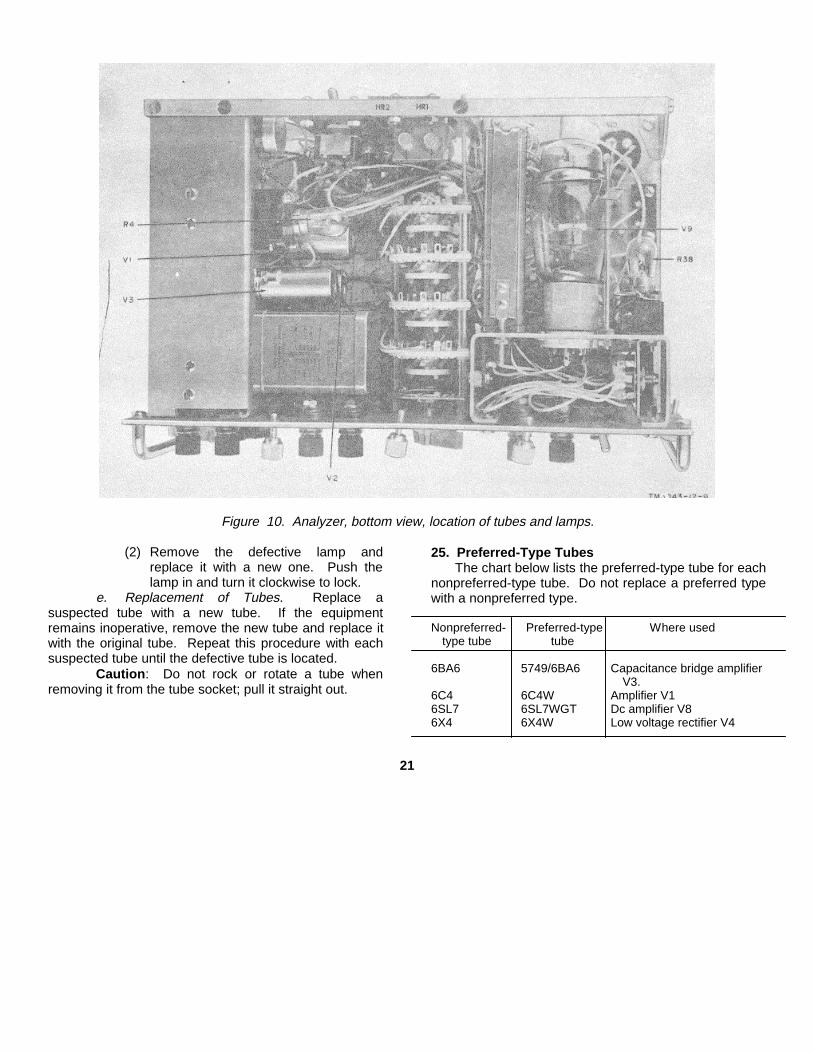
Figure 10. Analyzer, bottom view, location of tubes and lamps.
(2) Remove the defective lamp andreplace it with a new one. Push thelamp in and turn it clockwise to lock.
e. Replacement of Tubes. Replace asuspected tube with a new tube. If the equipmentremains inoperative, remove the new tube and replace itwith the original tube. Repeat this procedure with eachsuspected tube until the defective tube is located.
Caution: Do not rock or rotate a tube whenremoving it from the tube socket; pull it straight out.
25. Preferred-Type TubesThe chart below lists the preferred-type tube for each
nonpreferred-type tube. Do not replace a preferred typewith a nonpreferred type.
Nonpreferred- Preferred-type Where usedtype tube tube
6BA6 5749/6BA6 Capacitance bridge amplifierV3.
6C4 6C4W Amplifier V16SL7 6SL7WGT Dc amplifier V86X4 6X4W Low voltage rectifier V4
21

CHAPTER 5
SHIPMENT, LIMITED STORAGE, AND DEMOLITION TO PREVENTENEMY USE
Section I. SHIPMENT AND LIMITED STORAGE
26. Disassembly of EquipmentTo disassemble the analyzer, proceed as follows:
a. Disconnect the power cable from the powersource. Coil the power cable and tie it with twine.
b. Place the analyzer in the case.c. Secure the cover to the case.
27. Repackaging for Shipment or Limited Storage
a. If the original packing materials are onhand, use them and reverse the unpacking proceduresgiven in paragraph 8.
b. The prime requirement is to pack theequipment so as to prevent damage during transit orlimited storage. Package the equipment securely anduse sufficient wadding to minimize the effects of severejolting. Make sure the equipment is protected from rainand snow.
Section II. DEMOLITION OF MATERIEL TO PREVENT ENEMY USE
28. Authority for DemolitionDemolition of the equipment will be accomplished
only upon the order of the commander. The destructionprocedures outlined in paragraph 29 will be used toprevent further use of the equipment.
29. Methods of DestructionAny or all of the methods of destruction given below
may be used. The time available is the major factor indetermining destruction methods.
a. Smash. Smash control knobs, meter,switches, control panel, case, vacuum tubes, tubesockets, transformers, terminal boards, fuses, and the
drum and scale assembly; use sledges, axes, pickaxes,hammers, crowbars, or other heavy tools.
b. Cut. Cut the power cable and internalwiring; use handaxes, axes, or machetes.
c. Burn. Burn instruction manuals and wiring;use gasoline, kerosene, oil, flame throwers, or incendiarygrenades.
Warning: Be extremely careful with explosivesand incendiary devices. Use these items only when theneed is urgent.
d. Explode. If explosives are necessary, usefirearms, grenades, or TNT.
e. Dispose. Bury or scatter the destroyedparts or throw them into nearby waterways.
22

APPENDIX I
REFERENCES
Following is a list of capacitor specifications: MIL-C-81A Capacitors, Variable, Ceramic-Dielec-MIL-C-5A Capacitors, Fixed, Mica-Dielectric tric.MILC-20B Capacitors, Fixed, Ceramic-Dielectric MIL-C-91A Capacitors, Fixed, Paper-Dielectric
(Temperature Compensating) (Nonmetallic Cases).MIL-C-25A Capacitors, Fixed, Paper-Dielectric, Di- MILC-3965 Capacitors, Fixed, Electrolytic (Tan-
rect-Current (Hermetically Sealed in talum).Metallic Cases) MILC-11015A Capacitors, Fixed, Ceramic-Dielectric
MILC-62A Capacitors, Fixed, Electrolytic (DC, (General Purpose).Aluminum, Dry Electrolytic, Polar- JAN-C-92 Capacitors, Air-Dielectric, Variableized) (Trimmer Capacitors).
23

APPENDIX II
MAINTENANCE ALLOCATION CHART
1. GeneralThe maintenance allocation portion of this manual
assigns maintenance functions and repair operations tobe performed by the lowest appropriate maintenanceechelon.2. Explanation of columns
a. Part or Component. Only the nomenclatureor standard item name is used in this column. Additionaldescriptive data are included only where clarification isnecessary to identify the part. Components and partscomprising a major end item are listed alphabetically.Assemblies and subassemblies are in alphabeticalsequence with their components listed alphabeticallyimmediately below the assembly listing.
b. Related Operation. This column indicatesthe various maintenance functions allocated to theechelon capable of performing the operation.
(1) Service. To clean, to preserve, and toreplenish fuel and lubricants.
(2) Adjust. To regulate periodically toprevent malfunction.
(3) Inspect. To verify serviceability and todetect incipient electrical or mechanicalfailure by scrutiny.
(4) Test. To verify serviceability and todetect incipient electrical or mechanicalfailure by use of special equipmentsuch as gages, meters, etc.
(5) Replace. To substitute serviceableassemblies, subassemblies, and partsfor unserviceable components.
(6) Repair. To restore to a serviceablecondition by replacing unserviceableparts or by any other action requiredutilizing tools, equipment and skillsavailable, to include welding, grinding,riveting, straightening, adjusting, etc.
(7) Aline. To adjust two or morecomponents of an electrical system sothat their functions are properlysynchronized.
(8) Calibrate. To determine, check, orrectify the graduation of an instrument,weapon, or weapons system, orcomponents of a weapons system.
(9) Rebuild. To restore to a conditioncomparable to new by disassemblingthe item to determine the condition ofeach of its component parts andreassembling it using serviceable,rebuilt, or new assemblies,subassemblies, and parts.
c. Echelon Allocated the MaintenanceOperation. The symbol X placed in the appropriatecolumn indicates the echelon responsible for performingthat particular maintenance operation, but does notnecessarily indicate that repair parts will be stocked atthat level. Echelons higher than the echelon marked "X"are authorized to perform the indicated operation.
d. Repair Facilities Code. Code numbers areassigned to each individual tool equipment, testequipment and maintenance equipment referencedunder facilities required for maintenance operations. Thegrouping of codes in the repair facilities code column ofthe maintenance allocation chart indicates the tool, testand maintenance equipment required to perform themaintenance operation.
e. Remarks. Entries in this column will beutilized when necessary to clarify any of the data cited inthe preceding columns.
f. Facilities Required For MaintenanceOperations. Tools, test and maintenance equipmentrequired to perform the maintenance functions are listedin this column and coded in the repair facilities codecolumn. The plus sign indicates the echelons allocatedthe facility.
24

(1) (2) (3) (4) (5) (6) (7) (8)
RELATED 1ST 2ND 3RD 4TH 5TH REPAIRPART OR COMPONENT OPERATION ECH ECH ECH ECH ECH FACILITIES REMARKS
CODE
ANALYZER ZM-3/U; ZM-3A/Ucalibrate X 1,2,4,5,6,7,8adjust X 1,3,5,6,7,8service X 8 or 9 or 10rebuild X 8inspect X
ALUMINUM ALLOY BAR: (structural bars to support replace X 8 Fabricate if requiredcomponents)
ARRESTER, ELECTRICAL replace X 8test X 1
BALL, BEARING: (positions drum assembly gear) replace X 8 Obtain from salvage if requiredservice X 8inspect X
BLOCK: (supports drum assembly shaft) replace X 8 Fabricate if requiredBRACKET: (supports and mounts chassis components) replace X 8 Fabricate if requiredBUSHING: (AC line cord and drum assembly) replace X 8 Fabricate if required
service X 8inspect X
BUTTON, PLUG: (dust cover) replace X 8 Fabricate it requiredCABLE, POWER, ELECTRICAL: (cable assembly) replace X 8 or 9 or 10
inspect XCABLE ASSMIBLY, POWER, ELECTRICAL: (AC line cord) repair X 8 or 9 or 10 Fabricate when required. Cable and
connector available as maintenance partsreplace X 8 or 9 or 10inspect X
CAP, ELECTRICAL: (fuseholder) replace Xinspect X
CAPACITOR replace X 6,8inspect Xtest X 6,8
CASE, TEST SET: (carrying case) repair X 8 or 9 or 10 Spring catches onlyreplace X 8 Fabricate if required
CHASSIS, ELECTRICAL EQUIPMENT replace X 8 Fabricate if requiredCLIP, ELICTRICAL: (Electron Tube V9) replace X 8 or 9 or 10
inspect XCONNECTOR, PLUG: (cable assembly) replace X 8 or 9 or 10
inspect X
ZM-3/U; ZM-3A/U
25

(1) (2) (3) (4) (5) (6) (7) (8)
RELATED 1ST 2ND 3RD 4TH 5TH REPAIRPART OR COMPONENT OPERATION ECH ECH ECH ECH ECH FACILITIES REMARKS
CODE
ZU-3/U; 21-3A/U (continued)DIAL, SCALE: (drum assembly) replace X 8
inspect Xservice X 8
DRUM, FACSIMILE replace X 8DUST COVER: (test set) replace X 8 Obtain from salvage if requiredELECTRON TUBE replace X
test X 3test X 2inspect X
FUSE, CARTRIDGE replace Xinspect X
FUSEHOLDER replace X 8 or 9 or 10inspect X
GEAR: (drum assembly) replace X 8inspect Xservice X 8
GROMMET, RUBBER replace X 8 Available in Maintenance Equipment ME-9HANDLE, BOW replace X 8 Fabricate if requiredHEATING ELEMENT, ELECTRICAL replace X 8 or 9 or 10
inspect XHUB: (gear alignment) replace X 8 Fabricate if required
inspect XINSULATOR, PLATE: (fuse mounting) replace X 8 Fabricate if required
inspect XKNOB: (except knob for Switch 56) replace X 8 or 9 or 10KNOB: (Switch 56) replace X 8 Fabricate if requiredLAMP, INCANDESCENT: replace X
test X 1inspect X
LAMPHOLDER replace X 8 or 9 or 10inspect X
LENS, INDICATOR LIGHT replace XLIGHT, INDICATOR replace X 8 or 9 or 10
inspect XMASK, DIAL replace X 8 Fabricate if required
inspect XMOUNTING: (heating elements) replace X 8 Fabricate if required
inspect X
ZM-3/U; ZM-3A/U
26

(1) (2) (3) (4) (5) (6) (7) (8)
RELATED 1ST 2ND 3RD 4TH 5TH REPAIRPART OR COMPONENT OPERATION ECH ECH ECH ECH ECH FACILITIES REMARKS
CODE
ZM-3/U; ZM-3A/U (continued)MULTIMETER, REPLACEMENT replace X 8
repair X 5,8inspect X 8
NUT: (common hardware) replace X 8 or 9 or 10 Available in Hardware Kit MK-41/U and MaintenanceEquipment ME-9
PANEL, INDICATOR: (front control panel) replace X 8 Fabricate if requiredPIN: (drum assembly) replace X 8 Fabricate if requiredPLATE replace X 8 Fabricate if requiredPOST, BINDING replace X 8 or 9 or 10
inspect XPULLEY: (drum assembly) replace X 8 Fabricate if requiredRESISTOR replace X 8
test X 1inspect X
RETAINER, ELECTRON TUBE replace XRING, RETAINING: (drum assembly) replace X 8 Fabricate if requiredRIVET, TUBULAR replace X 8 Substitute available in Hardware Kit MK-41/USCREW: (common hardware) replace X 8 or 9 or 10 Available in Hardware Kit MK-41/U and Maintenance
Equipment ME-9SEMI-CONDUCTOR DEVICE, D10ODE replace X 8
test X 7SLISCREW replace X 8 or 9 or 10 Fabricate if requiredSHIELD, ELECTRON TUBE replace XSOCKET, ELECTRON TUBE replace X 8
inspect XSPACER, SLEEVE: (panel assembly) replace X 8 Fabricate if requiredSPIDER: (drum dial) replace X 8 Fabricate if requiredSPRING, HELICAL, EXTENSION: (drum assembly) replace X 8
ZM-3/U; ZM-3A/U
27

(1) (2) (3) (4) (5) (6) (7) (8)
RELATED 1ST 2ND 3RD 4TH 5TH REPAIRPART OR COMPONENT OPERATION ECH ECH ECH ECH ECH FACILITIES REMARKS
CODE
ZM-3/U; ZM-3A/U (continued)STEEL BAR, CORROSION RESISTANT, COLD FINISHED: (drum replace X 8 Fabricate if required
assembly)STUD, PLAIN: (resistor mounting) replace X 8 Fabricate if requiredSTUD, THREADED replace X 8 Fabricate if requiredSWITCH: (except Switch S7) replace X 8
inspect Xtest X 1
SWITCH, TOGGLE: S7 replace X 8 or 9 or 10TERMINAL, LUG: (wire connections) replace X 8 Available in Maintenance Equipment ME-9TERMINAL BOARD replace X 8 Fabricate if required. Plastic sheet and terminals
available in Maintenance Equipment ME-9inspect X
TEST SET SUB-ASSEIBLY: (dial drum assembly) replace X 8service X 8
THUMBSCREW: (dust cover) replace XTRANSFORMER replace X 8
test X 1inspect X
WASHER: (plastic) replace X 8 Fabricate if requiredWASHER: (steel, common hardware) replace X 8 or 9 or 10 Available in Hardware Kit MK-41/U and Maintenance
Equipment ME-9
ZM-3/U; aZ-3A/U
28

(1) (2) (3) (4) (5) (6) (7) (8)
1ST 2ND 3RD 4TH 5TH REPAIRFACILITIES REQIRED FOR MAINTENANCE OPERATIONS ECH ECH ECH ECH ECH FACIL- REMARKS
ITIES
CODE
ZM-3/U; ZM-3A/U (continued)MULTIMETER AN/URM-105 ( ) t t 1TEST SET ELECTRON TUBE TV-2( )/U t 2TEST SET ELECTRON TUBE TV-7( )/U t 3METER TESTER TS-656( )/U t 4METER TEST EQUIPMENT AN/GSM-1 ( ) t t 5TEST SET, CAPACITANCE-INDUCTANCE-RESISTANCE AN/URM-90( ) t t 6CRYSTAL RECTIFIER TEST SET TS-268E/U t t 7TOOL EQUIPUENT TK-21/G t t t t 8 Depending on the various repairman operators, toolTOOL EQUIPIENT TE-113 t t 9 equipments 8 or 9 or 10 will be available at 2ndTOOL EQUIPMENT TE-49 t t 10 echelon. 2nd echelon level of maintenance is performed
at 3rd echelon. Lowest using organization is a 3rdechelon organization.
ZM-3/U; ZM-3A/U
29

[AG 413.44 (22 Apr 58)]By Order of Wilber M. Brucker, Secretary of the Army:
MAXWELL D. TAYLOR,General, United States Army,
Official: Chief of Staff.
HERBERT M. JONES,Major General, United States Army,
The Adjutant General.
Distribution:Active Army:
ASA (2) Gen Depots (2) except Atlanta Gen USA Elect PG (1)CNGB (1) Depot (none) Picatinny Arsenal (5)Technical Stf, DA (1) except Sig Sec, Gen Depots (10) Frankford Arsenal (5)CSigO (30) Sig Depots (17) Sig Fld Maint Shops (3)Technical Stf Bd (1) Fld Comd, AFSWP (5) Sig Lab (5)USA Arty Bd (1) USA Sp Warfare Cen (5) Mil Dist (1)USA Armor Bd (1) Engr Maint Cen (1) Sectors, US Army Corps (Res) (1)USA Inf Bd (1) Army Pictorial Cen (2) US Army Corps (Res) (1)USA Air Def Bd (1) Madigan AH (5) JBUSMC (2)USA Abn & Elct Bd (1) WRAMC (1) Units organized under followingUSA Avn Bd (1) Brooke AH (5) TOE’s:USA Armor Bd Test Sec (1) AFIP (1) 9-500 (AA-AC) (2)USA Air Def Bd Test Sec (1) AMS (1) 11-7 (2)USA Arctic Test Bd (1) Ports of Emb (OS) (2) 11-15 (2)USCONARC (5) Trans Terminal Comd (2) 11-16 (2)US ARADOM (2) Army Terminals (2) 11-26 (2)OS Maj Comd (5) OS Sup Agcy (2) 11-57 (2)Log Comd (5) USA Sig Pub Agey (8) 11-127 (2)MDW (1) USA Sig Comm Engr Agey (1) 11-128 (2)Armies (5) USA Comm Agcy (2) 11-500 (AA-AE) (2)Corps (2) TASSA (13) 11-537 (2)Div (2) Mid-Western Rgn Ofc (1) 11-557 (2)USATC (2) USA Sig Eqp Spt Agey (2) 11-587 (2)Ft & Camps (2) USA White Sands Sig Agey (13) 11-592 (2)Svc Colleges (2) Yuma Test Sta (2) 11-597 (2)Br Svc Sch (5) except USASCS (25) Aberdeen PG (5) 20-300 (2)
NG: State AG (6); units-same as Active Army except allowance is one copy to each unit.USAR: None.For explanation of abbreviations used, see AR 320-50.
U.S. GOVERNMENT PRINTING OFFICE : 1994 O - 300-421 (01129)
30


PIN: 018693-000

This fine document...
Was brought to you by me:
Liberated Manuals -- free army and government manuals
Why do I do it? I am tired of sleazy CD-ROM sellers, who take publicly available information, slap “watermarks” and other junk on it, and sell it. Those masters of search engine manipulation make sure that their sites that sell free information, come up first in search engines. They did not create it... They did not even scan it... Why should they get your money? Why are not letting you give those free manuals to your friends?
I am setting this document FREE. This document was made by the US Government and is NOT protected by Copyright. Feel free to share, republish, sell and so on.
I am not asking you for donations, fees or handouts. If you can, please provide a link to liberatedmanuals.com, so that free manuals come up first in search engines:
<A HREF=http://www.liberatedmanuals.com/>Free Military and Government Manuals</A>
– SincerelyIgor Chudovhttp://igor.chudov.com/